visible-spanning flat supercontinuum for astronomical...
TRANSCRIPT
JOURNAL OF LIGHTWAVE TECHNOLOGY 1
Visible-spanning flat supercontinuum forastronomical applications
Aakash Ravi, Matthias Beck, David F. Phillips, Albrecht Bartels, Dimitar Sasselov, Andrew Szentgyorgyi, andRonald L. Walsworth
Abstract—We demonstrate a broad, flat, visible supercontin-uum spectrum that is generated by a dispersion-engineeredtapered photonic crystal fiber pumped by a 1 GHz repetition rateturn-key Ti:sapphire laser outputting ∼ 30 fs pulses at 800 nm.At a pulse energy of 100 pJ, we obtain an output spectrum thatis flat to within 3 dB over the range 490-690 nm with a blue tailextending below 450 nm. The mode-locked laser combined withthe photonic crystal fiber forms a simple visible frequency combsystem that is extremely well-suited to the precise calibration ofastrophysical spectrographs, among other applications.
Index Terms—Supercontinuum generation, astro-comb
I. INTRODUCTION
DOPPLER spectroscopy of stars using high-resolutionastrophysical spectrographs enables the detection of ex-
oplanets through measurement of periodic variations in theradial velocity of the host star [1]. Since such measurementsare inherently photon-flux-limited and require spectral sen-sitivity much better than the resolution of the spectrograph,they require combining information from thousands of just-resolved spectral lines across the passband of the instru-ment. Doing this reliably over orbital timescales requires anextremely stable calibration source with a large bandwidthand uniform spectral coverage. State-of-the-art spectrographsused in Doppler exoplanet searches such as HARPS [2] andHARPS-N [3] operate in the visible wavelength range (400-700 nm). Laser frequency combs are well suited to calibratingthese instruments, and several “astro-comb” designs have beensuccessfully demonstrated to date (see Ref. [4] and referencestherein).
Existing astro-comb architectures are based on near-infraredsource combs (e.g. Ti:sapphire, Yb/Er fiber), so providing visi-ble calibration light for an astrophysical spectrograph typicallyrequires a nonlinear optical element to coherently shift andbroaden the source comb radiation. Early astro-combs derivedfrom Ti:sapphire source combs relied on second harmonicgeneration [5], [6] but had limited utility due to extremelylow output bandwidth (∼ 15 nm). This is a serious shortfallbecause the exoplanet detection sensitivity depends on the
A. Ravi is with the Department of Physics, Harvard University, Cambridge,MA 02138, USA e-mail: [email protected]
M. Beck and A. Bartels are with Laser Quantum GmbH, Max-Stromeyer-Str. 116, 78467 Konstanz, Germany.
D. F. Phillips, D. Sasselov and A. Szentgyorgyi are with the Harvard-Smithsonian Center for Astrophysics, 60 Garden St., Cambridge, MA 02138,USA.
R. L. Walsworth is with the Department of Physics, Harvard University,Cambridge, MA 02138 and also with the Harvard-Smithsonian Center forAstrophysics, 60 Garden St., Cambridge, MA 02138, USA.
(Dated: October 9, 2018)
bandwidth of the observed stellar light that is calibrated. Acalibration source with constant line spacing over a largerbandwidth can therefore enable more precise determinationof stellar Doppler shifts.
A better alternative to frequency doubling is to pump ahighly nonlinear photonic crystal fiber (PCF) with the sourcecomb to take advantage of supercontinuum generation [7], aneffect where a narrowband high-intensity pulse experiencesextreme spectral broadening as a result of interactions withthe medium through which it propagates. The dispersion andnonlinearity of PCFs may be engineered via suitable changesin geometry; for example, two commonly used parameters arethe pitch and the diameter of the air holes. PCFs also typicallyexhibit very high nonlinearities compared to standard opticalfibers due to their small effective mode field diameters. As aresult of these attractive properties, broadband supercontinuumgeneration using PCFs has found many applications, fromoptical coherence tomography [8] to carrier-envelope phasestabilization of femtosecond lasers [9], as well as calibrationof astrophysical spectrographs [10]–[14].
Beyond spectral bandwidth, another property that is desiredfor astronomical calibration applications is spectral flatness,i.e., low intensity variation across the band of the calibrationsource. Spectral flatness is valued because calibration precisionis both shot-noise- and CCD-saturation-limited. Therefore thelargest photoelectron count below CCD saturation per expo-sure provides the optimal calibration. This condition is bestfulfilled for a uniform intensity distribution over all the combpeaks [11].
In the present work, we show that careful dispersion-engineering of a PCF by tapering enables the productionof a very broad, flat, and high-intensity optical supercon-tinuum spectrum from pump radiation emitted by a turn-key Ti:sapphire comb. Previous attempts to produce such asupercontinuum from a Ti:sapphire comb have reported rela-tively low spectral coverage (500-620 nm) and large intensityvariations (∼ 10 dB) across the band [13]. A flat 235 nm-wide visible supercontinuum has been demonstrated using aYb:fiber comb [15], but at the expense of losses incurred byspectral flattening using a spatial light modulator [11].
II. FIBER GEOMETRY AND PARAMETERS
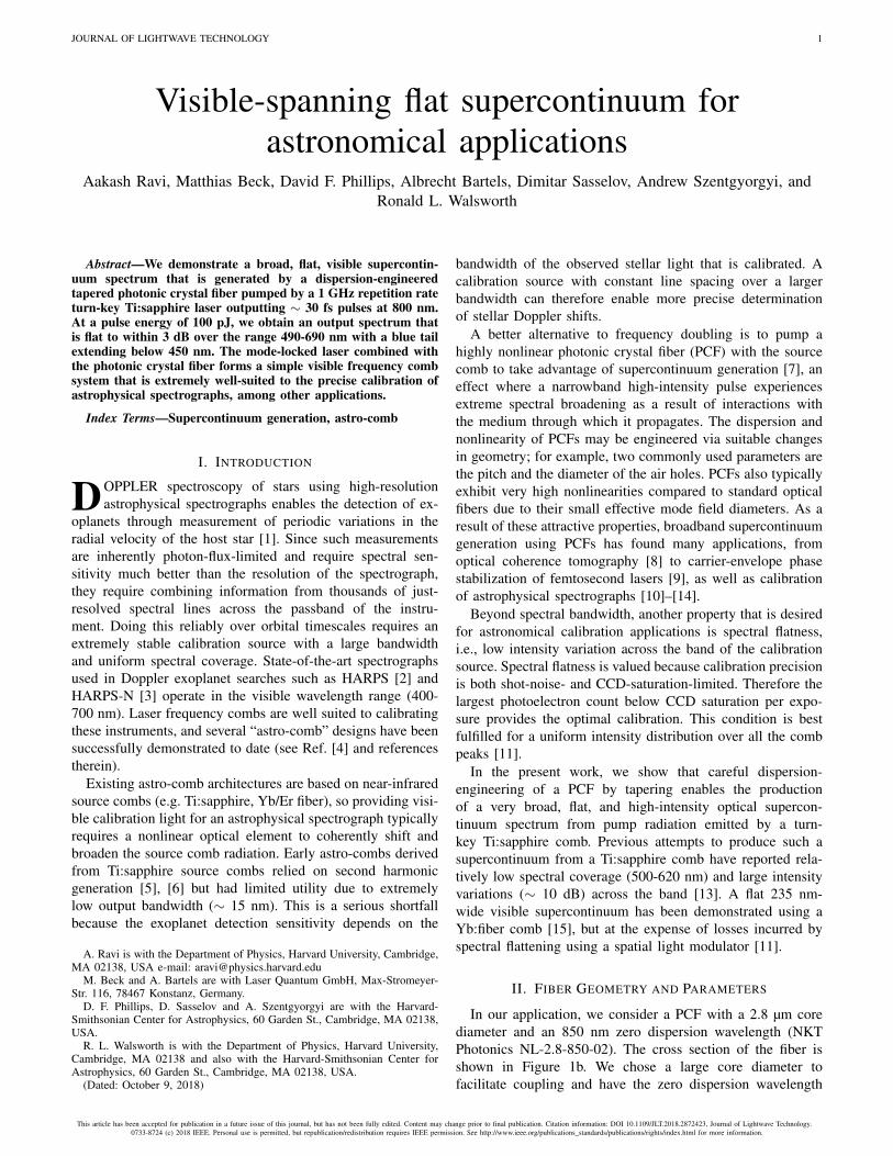
In our application, we consider a PCF with a 2.8 µm corediameter and an 850 nm zero dispersion wavelength (NKTPhotonics NL-2.8-850-02). The cross section of the fiber isshown in Figure 1b. We chose a large core diameter tofacilitate coupling and have the zero dispersion wavelength
This article has been accepted for publication in a future issue of this journal, but has not been fully edited. Content may change prior to final publication. Citation information: DOI 10.1109/JLT.2018.2872423, Journal of Lightwave Technology.0733-8724 (c) 2018 IEEE. Personal use is permitted, but republication/redistribution requires IEEE permission. See http://www.ieee.org/publications_standards/publications/rights/index.html for more information.
JOURNAL OF LIGHTWAVE TECHNOLOGY 2
d0
Lt
dw
LwL0 L1Lt
(c)
(b)(a)
Figure 1. (a) General tapered photonic crystal fiber (PCF) geometry showingvarying core size vs. length. The quantities d0, dw , L0,1, Lt1,2 , and Lwparametrize the geometry; see text for details. (b) SEM micrograph (courtesyof NKT Photonics A/S) of end face of NL-2.8-850-02 PCF. (c) Compositemicroscope image of fabricated tapered PCF. Overlaid red curves representthe proposed geometry, scaled by the cladding/core size ratio.
(ZDW) near our 800 nm pump wavelength. Changing thePCF core diameter as a function of distance along the fibervia tapering modifies both the dispersion and nonlinearity ofthe PCF. Sometimes termed “dispersion micromanagement” inthe literature, such techniques have been pursued before withPCFs to enable generation of light with increased bandwidthand flatness [16]–[19], but not targeted specifically towarduniform visible wavelength coverage using GHz repetition ratelasers.
To design a device capable of producing a flat visible-spanning spectrum when pumped with 800 nm femtosecondpulses, we model optical pulse propagation in the PCF by solv-ing the generalized nonlinear Schrödinger equation (GNLSE)as outlined in Appendix A. In our design, we consider aspecific taper geometry, as shown in Figure 1a. The corediameter d changes smoothly over the tapers with a cosinefunction d (ζ) = di+
12 (1− cosπζ) (df − di) over ζ ∈ [0, 1] ,
where di and df are, respectively, the initial and final corediameters of the down- or up-taper. More explicitly, di = d0,df = dw for the down-taper and di = dw, df = d0 for theup-taper. The nondimensionalized variable ζ parametrizes thedistance along the taper, i.e., ζ = (z − L0) /Lt1 for the down-taper and ζ = (z − (L0 + Lt1 + Lw)) /Lt2 for the up-taper.
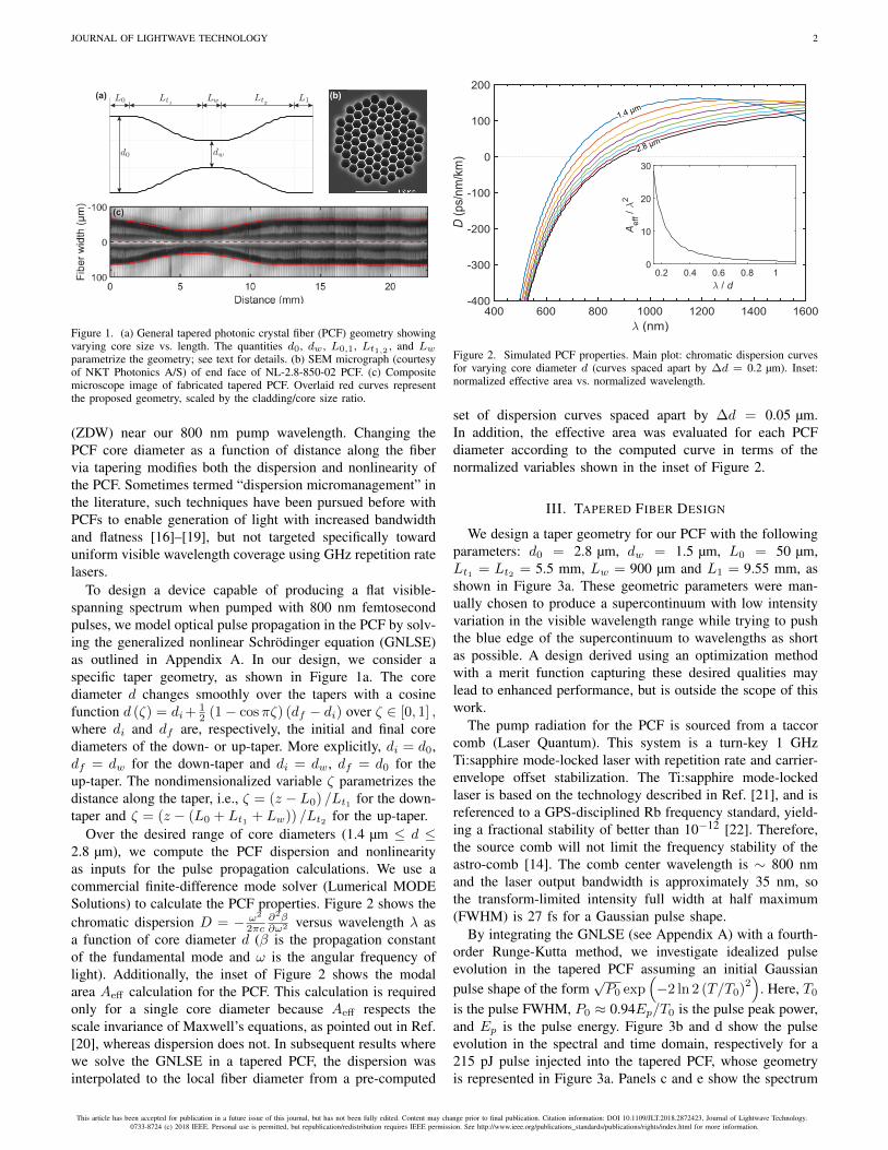
Over the desired range of core diameters (1.4 µm ≤ d ≤2.8 µm), we compute the PCF dispersion and nonlinearityas inputs for the pulse propagation calculations. We use acommercial finite-difference mode solver (Lumerical MODESolutions) to calculate the PCF properties. Figure 2 shows thechromatic dispersion D = − ω2
2πc∂2β∂ω2 versus wavelength λ as
a function of core diameter d (β is the propagation constantof the fundamental mode and ω is the angular frequency oflight). Additionally, the inset of Figure 2 shows the modalarea Aeff calculation for the PCF. This calculation is requiredonly for a single core diameter because Aeff respects thescale invariance of Maxwell’s equations, as pointed out in Ref.[20], whereas dispersion does not. In subsequent results wherewe solve the GNLSE in a tapered PCF, the dispersion wasinterpolated to the local fiber diameter from a pre-computed
400 600 800 1000 1200 1400 1600(nm)
-400
-300
-200
-100
0
100
200
D(p
s/nm
/km
)
2.8 μm
1.4 μm
0.2 0.4 0.6 0.8 1/ d
0
10
20
30
Aef
f/
2
Figure 2. Simulated PCF properties. Main plot: chromatic dispersion curvesfor varying core diameter d (curves spaced apart by ∆d = 0.2 µm). Inset:normalized effective area vs. normalized wavelength.
set of dispersion curves spaced apart by ∆d = 0.05 µm.In addition, the effective area was evaluated for each PCFdiameter according to the computed curve in terms of thenormalized variables shown in the inset of Figure 2.
III. TAPERED FIBER DESIGN
We design a taper geometry for our PCF with the followingparameters: d0 = 2.8 µm, dw = 1.5 µm, L0 = 50 µm,Lt1 = Lt2 = 5.5 mm, Lw = 900 µm and L1 = 9.55 mm, asshown in Figure 3a. These geometric parameters were man-ually chosen to produce a supercontinuum with low intensityvariation in the visible wavelength range while trying to pushthe blue edge of the supercontinuum to wavelengths as shortas possible. A design derived using an optimization methodwith a merit function capturing these desired qualities maylead to enhanced performance, but is outside the scope of thiswork.
The pump radiation for the PCF is sourced from a taccorcomb (Laser Quantum). This system is a turn-key 1 GHzTi:sapphire mode-locked laser with repetition rate and carrier-envelope offset stabilization. The Ti:sapphire mode-lockedlaser is based on the technology described in Ref. [21], and isreferenced to a GPS-disciplined Rb frequency standard, yield-ing a fractional stability of better than 10−12 [22]. Therefore,the source comb will not limit the frequency stability of theastro-comb [14]. The comb center wavelength is ∼ 800 nmand the laser output bandwidth is approximately 35 nm, sothe transform-limited intensity full width at half maximum(FWHM) is 27 fs for a Gaussian pulse shape.
By integrating the GNLSE (see Appendix A) with a fourth-order Runge-Kutta method, we investigate idealized pulseevolution in the tapered PCF assuming an initial Gaussianpulse shape of the form
√P0 exp
(−2 ln 2 (T/T0)
2)
. Here, T0
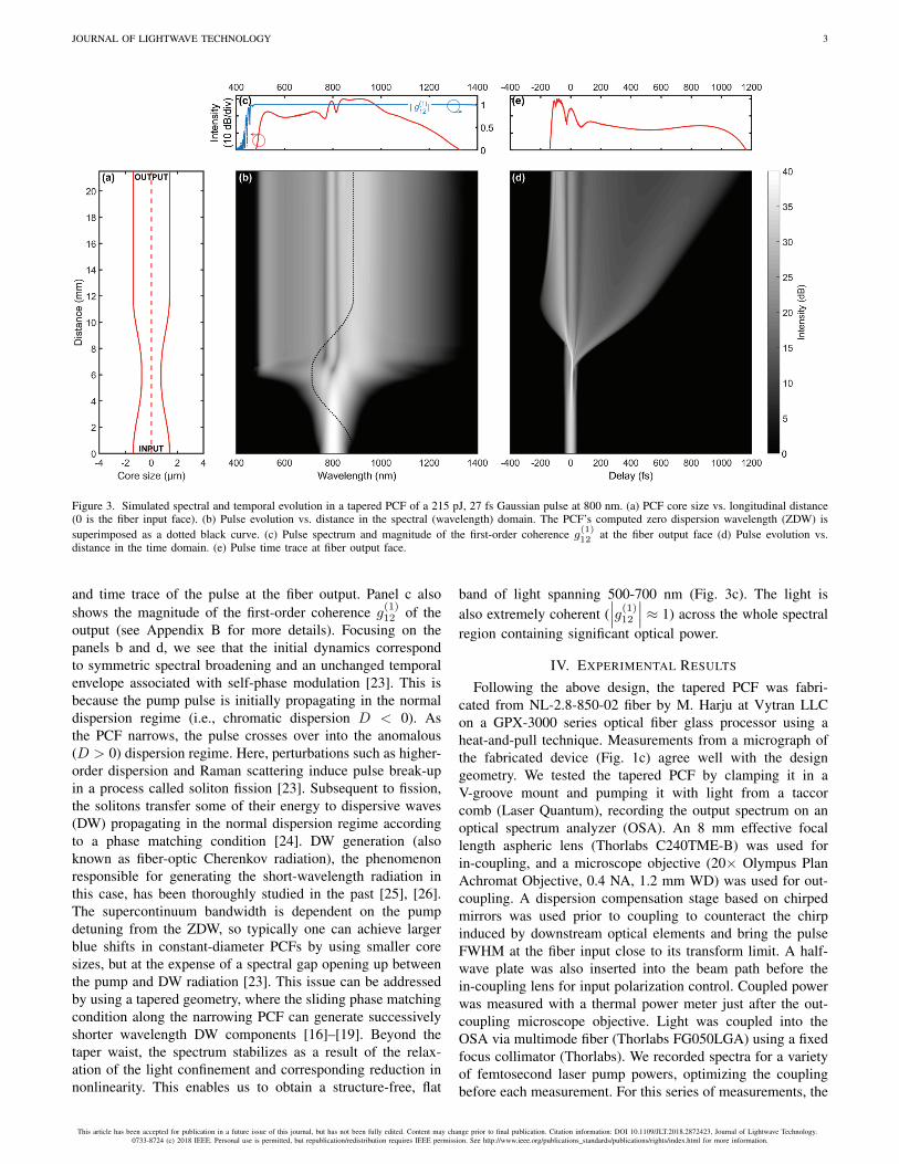
is the pulse FWHM, P0 ≈ 0.94Ep/T0 is the pulse peak power,and Ep is the pulse energy. Figure 3b and d show the pulseevolution in the spectral and time domain, respectively for a215 pJ pulse injected into the tapered PCF, whose geometryis represented in Figure 3a. Panels c and e show the spectrum
This article has been accepted for publication in a future issue of this journal, but has not been fully edited. Content may change prior to final publication. Citation information: DOI 10.1109/JLT.2018.2872423, Journal of Lightwave Technology.0733-8724 (c) 2018 IEEE. Personal use is permitted, but republication/redistribution requires IEEE permission. See http://www.ieee.org/publications_standards/publications/rights/index.html for more information.
JOURNAL OF LIGHTWAVE TECHNOLOGY 3
Figure 3. Simulated spectral and temporal evolution in a tapered PCF of a 215 pJ, 27 fs Gaussian pulse at 800 nm. (a) PCF core size vs. longitudinal distance(0 is the fiber input face). (b) Pulse evolution vs. distance in the spectral (wavelength) domain. The PCF’s computed zero dispersion wavelength (ZDW) issuperimposed as a dotted black curve. (c) Pulse spectrum and magnitude of the first-order coherence g(1)
12 at the fiber output face (d) Pulse evolution vs.distance in the time domain. (e) Pulse time trace at fiber output face.
and time trace of the pulse at the fiber output. Panel c alsoshows the magnitude of the first-order coherence g(1)
12 of theoutput (see Appendix B for more details). Focusing on thepanels b and d, we see that the initial dynamics correspondto symmetric spectral broadening and an unchanged temporalenvelope associated with self-phase modulation [23]. This isbecause the pump pulse is initially propagating in the normaldispersion regime (i.e., chromatic dispersion D < 0). Asthe PCF narrows, the pulse crosses over into the anomalous(D > 0) dispersion regime. Here, perturbations such as higher-order dispersion and Raman scattering induce pulse break-upin a process called soliton fission [23]. Subsequent to fission,the solitons transfer some of their energy to dispersive waves(DW) propagating in the normal dispersion regime accordingto a phase matching condition [24]. DW generation (alsoknown as fiber-optic Cherenkov radiation), the phenomenonresponsible for generating the short-wavelength radiation inthis case, has been thoroughly studied in the past [25], [26].The supercontinuum bandwidth is dependent on the pumpdetuning from the ZDW, so typically one can achieve largerblue shifts in constant-diameter PCFs by using smaller coresizes, but at the expense of a spectral gap opening up betweenthe pump and DW radiation [23]. This issue can be addressedby using a tapered geometry, where the sliding phase matchingcondition along the narrowing PCF can generate successivelyshorter wavelength DW components [16]–[19]. Beyond thetaper waist, the spectrum stabilizes as a result of the relax-ation of the light confinement and corresponding reduction innonlinearity. This enables us to obtain a structure-free, flat
band of light spanning 500-700 nm (Fig. 3c). The light isalso extremely coherent (
∣∣∣g(1)12
∣∣∣ ≈ 1) across the whole spectralregion containing significant optical power.
IV. EXPERIMENTAL RESULTS
Following the above design, the tapered PCF was fabri-cated from NL-2.8-850-02 fiber by M. Harju at Vytran LLCon a GPX-3000 series optical fiber glass processor using aheat-and-pull technique. Measurements from a micrograph ofthe fabricated device (Fig. 1c) agree well with the designgeometry. We tested the tapered PCF by clamping it in aV-groove mount and pumping it with light from a taccorcomb (Laser Quantum), recording the output spectrum on anoptical spectrum analyzer (OSA). An 8 mm effective focallength aspheric lens (Thorlabs C240TME-B) was used forin-coupling, and a microscope objective (20× Olympus PlanAchromat Objective, 0.4 NA, 1.2 mm WD) was used for out-coupling. A dispersion compensation stage based on chirpedmirrors was used prior to coupling to counteract the chirpinduced by downstream optical elements and bring the pulseFWHM at the fiber input close to its transform limit. A half-wave plate was also inserted into the beam path before thein-coupling lens for input polarization control. Coupled powerwas measured with a thermal power meter just after the out-coupling microscope objective. Light was coupled into theOSA via multimode fiber (Thorlabs FG050LGA) using a fixedfocus collimator (Thorlabs). We recorded spectra for a varietyof femtosecond laser pump powers, optimizing the couplingbefore each measurement. For this series of measurements, the
This article has been accepted for publication in a future issue of this journal, but has not been fully edited. Content may change prior to final publication. Citation information: DOI 10.1109/JLT.2018.2872423, Journal of Lightwave Technology.0733-8724 (c) 2018 IEEE. Personal use is permitted, but republication/redistribution requires IEEE permission. See http://www.ieee.org/publications_standards/publications/rights/index.html for more information.
JOURNAL OF LIGHTWAVE TECHNOLOGY 4
Experiment
400 500 600 700 800 900
Wavelength (nm)
Inte
nsity
(lin
ear
scal
e, a
rb.)
Simulation
400 500 600 700 800 900
Wavelength (nm)
incr
easi
ng p
ulse
ene
rgy
(i)
(ii)
(iii)
(iv)
(i)
(ii)
(iii)
(iv)
0.25x
0.25x
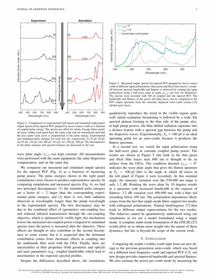
Figure 4. Comparison of experimental (left panel) and simulated (right panel)output spectra from tapered PCF pumped by taccor source comb as a functionof coupled pulse energy. The spectra are offset for clarity. Except where noted,all traces within each panel have the same scale and are normalized such thatthe area under each curve is proportional to the pulse energy. Experimentaland simulated pulse energies for each row are, respectively, (i) 24 pJ, 50 pJ,(ii) 63 pJ, 130 pJ, (iii) 100 pJ, 215 pJ, (iv) 190 pJ, 290 pJ. The discrepanciesin the pulse energies and spectral features are discussed in the text.
wave plate angle φλ/2 was kept constant. All measurementswere performed with the same equipment, the same dispersioncompensation, and on the same day.
We compared our measured and simulated output spectrafor the tapered PCF (Fig. 4) as a function of increasingpump power. The pulse energies shown in the right panel(simulations) were chosen to produce representative spectra. Incomparing simulations and measured spectra (Fig. 4), we findtwo principal discrepancies: (1) the simulated pulse energiesare a factor of ∼ 2 larger than the corresponding experi-mental pulse energies, and (2) there is very little radiationobserved at wavelengths longer than the pump wavelengthin the experimental spectra. The first discrepancy may bedue to the combined effect of (geometric) out-coupling lossand reduced infrared transmission through the out-couplingobjective, which is optimized for visible light; this mechanismlowers the measured out-coupled power compared to simulatedspectra since the power is measured after the objective. Theseeffects are thought to also contribute to the second discrep-ancy to some extent, but it is suspected that the dominantcontribution comes from chromatic effects in coupling intothe multimode fiber used with the OSA. Finally, there areuncertainties in fiber properties (both geometric and optical)and laser parameters (e.g., coupled bandwidth) which lead touncertainties in the expected spectral profiles.
Despite the differences described above, the simulations
450 500 550 600 650
Wavelength (nm)
Inte
nsity
(lin
ear
scal
e, a
rb.)
/2= 0°
/2= 10°
Current astro-comb system
Figure 5. Measured output spectra for tapered PCF pumped by taccor sourcecomb at different input polarizations (thin green and thick blue traces): a trade-off between spectral bandwidth and flatness is observed by rotating the inputpolarization using a half-wave plate at angle φλ/2 (see text for definition).The spectra were recorded with 100 pJ coupled into the tapered PCF. Thebandwidth and flatness of the green and blue traces can be compared to thePCF output spectrum from the currently deployed astro-comb system [13](dotted gray trace).
qualitatively reproduce the trend in the visible region quitewell: initial symmetric broadening is followed by a wide, flatspectral plateau forming to the blue side of the pump; also,at high pump powers, the blue-shifted radiation separates intoa distinct feature with a spectral gap between the pump andthe dispersive waves. Experimentally, Ep ≈ 100 pJ is an idealoperating point for an astro-comb, because it produces theflattest spectrum.
In a second test, we varied the input polarization usingthe half-wave plate at constant coupled pump power. Theresults are shown in Figure 5 (the kink in the thin greenand thick blue traces near 600 nm is thought to be anartifact from the OSA). The condition denoted φλ/2 = 0◦
indicates the wave plate angle that gives the flattest spectrumat Ep = 100 pJ (this is the angle at which all traces inthe left panel of Figure 4 were recorded). At this nominalangle, the intensity variation over the 530-690 nm range isonly 1.2 dB. Rotating the wave plate by 10 degrees resultsin a spectrum with increased bandwidth at the expense offlatness: 3.2 dB variation over 490-690 nm, with a blue tailextending below 450 nm. The polarization dependence likelycomes from the fact that single-mode fibers support two modeswith orthogonal polarizations. Natural birefringence [7] thenleads to different output supercontinua for the two modes.This behavior cannot be quantitatively understood using oursimulations as we use a model formulated using a singlemode. A complete multi-mode formulation of the GNLSE [27]would allow us to obtain more insight into the nature of thesedynamics, but this is beyond the scope of the current work.
V. CONCLUSION
Comparing the usable (visible) comb light from our new de-sign to the previous-generation astro-comb, which was basedon a different laser frequency comb and tapered PCF [13], ournew design provides improved bandwidth and spectral flatness.We also estimate the power per comb mode by measuring the
This article has been accepted for publication in a future issue of this journal, but has not been fully edited. Content may change prior to final publication. Citation information: DOI 10.1109/JLT.2018.2872423, Journal of Lightwave Technology.0733-8724 (c) 2018 IEEE. Personal use is permitted, but republication/redistribution requires IEEE permission. See http://www.ieee.org/publications_standards/publications/rights/index.html for more information.

JOURNAL OF LIGHTWAVE TECHNOLOGY 5
transmission through a 10 nm-wide bandpass filter around 532nm, obtaining values of ∼ 102 nW/mode, which is comparableto the result in Ref. [13]. It thus satisfies the requirements forthe astro-comb application. Moreover, the new tapered PCFenables the use of a turn-key Ti:sapphire laser, which greatlysimplifies astro-comb design and operation [14].
Our new astro-comb (employing the turn-key laser andtapered PCF described in this work) is expected to reacha radial velocity precision of < 10 cm/s (i.e., < 200 kHz inunits of optical frequency) in a single exposure, requiredfor detection of terrestrial exoplanets in the habitable zonearound Sun-like stars. This is similar to results demonstratedin Ref. [14] using the same laser. Once the new astro-combis fully deployed, we will verify the stability by injectingthe astro-comb light into both channels of the astrophysicalspectrograph simultaneously and compute the two-sample de-viation of the spectral shift between channels as a function ofaveraging time [13], [14]. The next major step is to improvethe residual dispersion of the Fabry-Perot mode filters [28]used for repetition rate multiplication, so as to preserve all ofthe bandwidth generated by the PCF. Another viable optionwould be to split the comb light into several bands and filtereach band separately using narrowband cavities [29].
In addition to the calibration of astrophysical spectrographsused for Doppler velocimetry of stars, our tapered PCF designmay find applications in optical coherence tomography (OCT)[8]. In OCT systems, the axial (spatial) resolution scales as∼ λ2
0/ (∆λ), where λ0 is the center wavelength and ∆λ is thebandwidth of the source. Hence, the resolution benefits fromreducing the center wavelength and increasing the bandwidth,which is a similar design problem to the one addressed here.Ultrahigh-resolution visible-wavelength OCT has enabled op-tical sectioning at the subcellular level [30] as well high-speedinspection of printed circuit boards [31]. In such applications,spectral gaps in the output band of supercontinuum sourcesused in OCT studies degrade the axial resolution below thatpossible with the full band. Thus, the spectral uniformitypossible from the present tapered PCF design may improveresolution further; it may also obviate some of the challengesassociated with dual-band OCT, where sophisticated signal-processing techniques are required to combine informationfrom spectrally separated bands [32].
In summary, we demonstrated a tapered PCF that producesspectrally flat light almost spanning the entire visible rangewhen pumped by a turn-key GHz Ti:sapphire laser. Our resultrepresents a marked improvement in the amount of opticalbandwidth available to calibrate a visible-wavelength spectro-graph. This work also enables a simple visible frequency combsystem without the need for spectral shaping.
APPENDIX ATHEORETICAL MODEL
We describe the propagation of optical pulses in PCFs usingthe generalized nonlinear Schrödinger equation (GNLSE).Here, we work in the interaction picture and use a frequency
domain formulation, following Ref. [33]. The GNLSE [23] isexpressed as
∂
∂zAI = iγ (ω) exp (−D (ω) z)
×F{A (z, T )×
(R (T ) ∗
∣∣A (z, T )∣∣2)} . (1)
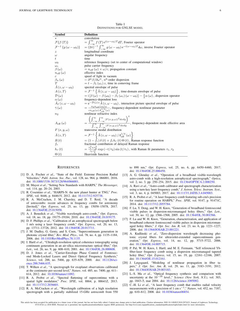
Table I summarizes the definitions of all symbols used above.In terms of the GNLSE, the PCF is entirely described byD (ω), γ (ω) and R (t). The fiber material is fused silica, sowe take fr = 0.18, τ1 = 12.2 fs, and τ2 = 32 fs as givenin Ref. [34], and n2 ≈ 2.5 × 10⁻²⁰ m2/W [35] for all ourcalculations. We neglect any losses, i.e., α (ω) = 0 dB/m.
Note that in tapered geometries, both the dispersion op-erator and the frequency-dependent nonlinear parameter be-come functions of z as well, i.e., D (ω) → D (ω, z) andγ (ω) → γ (ω, z) [36], [37]. This approach has been pointedout to not be strictly correct as it does not conserve the photonnumber [20], [38], but we have adopted it here for simplicity.Our solver codes and data are available online [39].
APPENDIX BCALCULATION OF SUPERCONTINUUM COHERENCE
We use a first-order measure g(1)12 to evaluate the coherence
[7] of the output optical field A(ω) from the PCF,
∣∣∣g(1)12 (ω)
∣∣∣ =
∣∣∣∣⟨A∗i (ω) Aj (ω)⟩i 6=j
∣∣∣∣√⟨∣∣∣Ai (ω)∣∣∣2⟩⟨∣∣∣Aj (ω)
∣∣∣2⟩ (2)
where 〈· · ·〉 is an ensemble average over N propagations ofthe simulation.
Each run of the simulation differs by some noise injectedinto the input field. We include only a shot noise seed and nospontaneous Raman noise, as shot noise has been shown to bethe dominant noise process [40]. To perturb the input pulse (inthe time domain), we follow Ref. [41], [42]: to each temporalbin of both the real and imaginary components of A (T ), weadd a random number drawn from a normal distribution withzero mean and variance hωc/ (4∆T ), where ωc is the pulsecarrier frequency and ∆T is the temporal bin width. In Figure3c, we evaluate
∣∣∣g(1)12
∣∣∣ over N = 100 runs of the simulation.
ACKNOWLEDGMENTS
The authors would like thank Guoquing Chang and FranzKärtner for supplying us with the NL-2.8-850-02 photoniccrystal fiber for the project, as well as for their thoughtfulreading of the manuscript. A. Ravi would also like to thankPawel Latawiec, Fiorenzo Omenetto, Liane Bernstein, JenniferSchloss, Matthew Turner, Timothy Milbourne, Gábor Furész,and Tim Hellickson for helpful discussions.
This research work was supported by the Harvard Originsof Life Initiative, the Smithsonian Astrophysical Observa-tory, NASA award no. NNX16AD42G, NSF award no. AST-1405606. A. Ravi was supported by a postgraduate scholarshipfrom the Natural Sciences and Engineering Research Councilof Canada.
This article has been accepted for publication in a future issue of this journal, but has not been fully edited. Content may change prior to final publication. Citation information: DOI 10.1109/JLT.2018.2872423, Journal of Lightwave Technology.0733-8724 (c) 2018 IEEE. Personal use is permitted, but republication/redistribution requires IEEE permission. See http://www.ieee.org/publications_standards/publications/rights/index.html for more information.
JOURNAL OF LIGHTWAVE TECHNOLOGY 6
Table IDEFINITIONS FOR GNLSE MODEL
Symbol Definition∗ convolutionF{f (T )} =
∫∞−∞ f (T ) ei(ω−ω0)T dT, Fourier operator
F−1 {g (ω − ω0)} = (2π)−1∫∞−∞ g (ω − ω0) e−i(ω−ω0)T dω, inverse Fourier operator
z longitudinal coordinateω angular frequencyt timeω0 reference frequency (set to center of computational window)ωc pulse carrier frequencyβ (ω) = neff (ω)× ω/c, propagation constantneff (ω) effective indexc speed of light in vacuumβn (ω) = ∂nβ/∂ωn, nth-order dispersionT = t− β1 (ωc) z, time in comoving frameA (z, ω − ω0) spectral envelope of pulseA (z, T ) = F−1
{A (z, ω − ω0)
}, time-domain envelope of pulse
D (ω) = i [β (ω)− β (ω0)− β1 (ωc) (ω − ω0)]− 12α (ω) , dispersion operator
α (ω) frequency-dependent lossAI (z, ω − ω0) = e−D(ω)zA (z, ω − ω0) , interaction picture spectral envelope of pulseγ (ω) =
n2neff (ω0)ω
cneff (ω)A1/4
eff(ω)
, frequency-dependent nonlinear parameter
n2 nonlinear refractive index
Aeff (ω) =
(∫∞−∞
∫∞−∞|F (x,y,ω)|2dxdy
)2∫∞−∞
∫∞−∞|F (x,y,ω)|4dxdy
, frequency-dependent mode effective area
F (x, y, ω) transverse modal distribution
A (z, T ) = F−1
{A (z, ω − ω0) /A
1/4eff
(ω)
}R (t) = (1− fr) δ (t) + frhr (t) Θ (t) , Raman response functionfr fractional contribution of delayed Raman response
hr (t) =τ21 +τ22τ1τ
22
exp (−t/τ2) sin (t/τ1) , with Raman fit parameters τ1, τ2Θ (t) Heaviside function
REFERENCES
[1] D. A. Fischer et al., “State of the Field: Extreme Precision RadialVelocities,” Publ. Astron. Soc. Pac., vol. 128, no. 964, p. 066001, 2016.doi: 10.1088/1538-3873/128/964/066001.
[2] M. Mayor et al., “Setting New Standards with HARPS,” The Messenger,vol. 114, pp. 20–24, 2003.
[3] R. Cosentino et al., “HARPS-N: the new planet hunter at TNG,” Proc.SPIE, vol. 8446, p. 84461V, 2012. doi: 10.1117/12.925738.
[4] R. A. McCracken, J. M. Charsley, and D. T. Reid, “A decadeof astrocombs: recent advances in frequency combs for astronomy[Invited],” Opt. Express, vol. 25, no. 13, pp. 15058–15078, 2017.doi: 10.1364/OE.25.015058.
[5] A. J. Benedick et al., “Visible wavelength astro-comb.,” Opt. Express,vol. 18, no. 18, pp. 19175–19184, 2010. doi: 10.1364/OE.18.019175.
[6] D. F. Phillips et al., “Calibration of an astrophysical spectrograph below1 m/s using a laser frequency comb,” Opt. Express, vol. 20, no. 13,pp. 13711–13726, 2012. doi: 10.1364/OE.20.013711.
[7] J. M. Dudley, G. Genty, and S. Coen, “Supercontinuum generation inphotonic crystal fiber,” Rev. Mod. Phys., vol. 78, no. 4, pp. 1135–1184,2006. doi: 10.1103/RevModPhys.78.1135.
[8] I. Hartl et al., “Ultrahigh-resolution optical coherence tomography usingcontinuum generation in an air-silica microstructure optical fiber,” Opt.Lett., vol. 26, no. 9, pp. 608–610, 2001. doi: 10.1364/OL.26.000608.
[9] D. J. Jones et al., “Carrier-Envelope Phase Control of Femtosec-ond Mode-Locked Lasers and Direct Optical Frequency Synthesis,”Science, vol. 288, no. 5466, pp. 635–639, 2000. doi: 10.1126/sci-ence.288.5466.635.
[10] T. Wilken et al., “A spectrograph for exoplanet observations calibratedat the centimetre-per-second level,” Nature, vol. 485, no. 7400, pp. 611–614, 2012. doi: 10.1038/nature11092.
[11] R. A. Probst et al., “Spectral flattening of supercontinua with aspatial light modulator,” Proc. SPIE, vol. 8864, p. 88641Z, 2013.doi: 10.1117/12.2036601.
[12] R. A. McCracken et al., “Wavelength calibration of a high resolutionspectrograph with a partially stabilized 15-GHz astrocomb from 550
to 890 nm,” Opt. Express, vol. 25, no. 6, pp. 6450–6460, 2017.doi: 10.1364/OE.25.006450.
[13] A. G. Glenday et al., “Operation of a broadband visible-wavelengthastro-comb with a high-resolution astrophysical spectrograph,” Optica,vol. 2, no. 3, pp. 250–254, 2015. doi: 10.1364/OPTICA.2.000250.
[14] A. Ravi et al., “Astro-comb calibrator and spectrograph characterizationusing a turn-key laser frequency comb,” J. Astron. Telesc. Instrum. Syst.,vol. 3, no. 4, p. 045003, 2017. doi: 10.1117/1.JATIS.3.4.045003.
[15] R. A. Probst et al., “A laser frequency comb featuring sub-cm/s precisionfor routine operation on HARPS,” Proc. SPIE, vol. 9147, p. 91471C,2014. doi: 10.1117/12.2055784.
[16] F. Lu, Y. Deng, and W. H. Knox, “Generation of broadband femtosecondvisible pulses in dispersion-micromanaged holey fibers,” Opt. Lett.,vol. 30, no. 12, pp. 1566–1568, 2005. doi: 10.1364/OL.30.001566.
[17] F. Lu and W. H. Knox, “Generation, characterization, and application ofbroadband coherent femtosecond visible pulses in dispersion microman-aged holey fibers,” J. Opt. Soc. Am. B, vol. 23, no. 6, pp. 1221–1227,2006. doi: 10.1364/JOSAB.23.001221.
[18] A. Kudlinski et al., “Zero-dispersion wavelength decreasing pho-tonic crystal fibers for ultraviolet-extended supercontinuum gen-eration,” Opt. Express, vol. 14, no. 12, pp. 5715–5722, 2006.doi: 10.1364/OE.14.005715.
[19] P. Pal, W. H. Knox, I. Hartl, and M. E. Fermann, “Self referenced Yb-fiber-laser frequency comb using a dispersion micromanaged taperedholey fiber,” Opt. Express, vol. 15, no. 19, pp. 12161–12166, 2007.doi: 10.1364/OE.15.012161.
[20] J. Lægsgaard, “Modeling of nonlinear propagation in fiber ta-pers,” J. Opt. Soc. Am. B, vol. 29, no. 11, pp. 3183–3191, 2012.doi: 10.1364/JOSAB.29.003183.
[21] L.-S. Ma et al., “Optical frequency synthesis and comparison withuncertainty at the 10−19 level.,” Science (New York, N.Y.), vol. 303,pp. 1843–5, mar 2004. doi: 10.1126/science.1095092.
[22] C.-H. Li et al., “A laser frequency comb that enables radial velocitymeasurements with a precision of 1 cm s−1,” Nature, vol. 452, no. 7187,pp. 610–612, 2008. doi: 10.1038/nature06854.
This article has been accepted for publication in a future issue of this journal, but has not been fully edited. Content may change prior to final publication. Citation information: DOI 10.1109/JLT.2018.2872423, Journal of Lightwave Technology.0733-8724 (c) 2018 IEEE. Personal use is permitted, but republication/redistribution requires IEEE permission. See http://www.ieee.org/publications_standards/publications/rights/index.html for more information.
JOURNAL OF LIGHTWAVE TECHNOLOGY 7
[23] J. M. Dudley and J. R. Taylor, eds., Supercontinuum Generation inOptical Fibers. Cambridge University Press, 2010.
[24] N. Akhmediev and M. Karlsson, “Cherenkov radiation emitted bysolitons in optical fibers,” Phys. Rev. A, vol. 51, no. 3, pp. 2602–2607,1995. doi: 10.1103/PhysRevA.51.2602.
[25] G. Chang, L.-J. Chen, and F. X. Kärtner, “Highly efficient Cherenkovradiation in photonic crystal fibers for broadband visible wave-length generation,” Opt. Lett., vol. 35, no. 14, pp. 2361–2363, 2010.doi: 10.1364/OL.35.002361.
[26] G. Chang, L.-J. Chen, and F. X. Kärtner, “Fiber-optic Cherenkov radi-ation in the few-cycle regime,” Opt. Express, vol. 19, no. 7, pp. 6635–6647, 2011. doi: 10.1364/OE.19.006635.
[27] F. Poletti and P. Horak, “Description of ultrashort pulse propagation inmultimode optical fibers,” J. Opt. Soc. Am. B, vol. 25, no. 10, pp. 1645–1654, 2008. doi: 10.1364/JOSAB.25.001645.
[28] L.-J. Chen et al., “Broadband dispersion-free optical cavities based onzero group delay dispersion mirror sets.,” Opt. Express, vol. 18, no. 22,pp. 23204–23211, 2010. doi: 10.1364/OE.18.023204.
[29] D. A. Braje, M. S. Kirchner, S. Osterman, T. Fortier, and S. A.Diddams, “Astronomical spectrograph calibration with broad-spectrumfrequency combs,” Eur. Phys. J. D, vol. 48, no. 1, pp. 57–66, 2008.doi: 10.1140/epjd/e2008-00099-9.
[30] P. J. Marchand et al., “Visible spectrum extended-focus opti-cal coherence microscopy for label-free sub-cellular tomography,”Biomed. Opt. Express, vol. 8, no. 7, pp. 3343–3359, 2017.doi: 10.1364/BOE.8.003343.
[31] J. Czajkowski et al., “Sub-micron resolution high-speed spectral domainoptical coherence tomography in quality inspection for printed electron-ics,” Proc. SPIE, vol. 8430, p. 84300K, 2012. doi: 10.1117/12.922443.
[32] P. Cimalla, M. Gaertner, J. Walther, and E. Koch, “Resolution im-provement in dual-band OCT by filling the spectral gap,” Proc. SPIE,vol. 8213, p. 82132M, 2012. doi: 10.1117/12.908331.
[33] J. Hult, “A Fourth-Order Runge-Kutta in the Interaction Pic-ture Method for Simulating Supercontinuum Generation in OpticalFibers,” J. Lightw. Technol., vol. 25, no. 12, pp. 3770–3775, 2007.doi: 10.1109/JLT.2007.909373.
[34] G. Agrawal, Nonlinear Fiber Optics. Academic Press, 5 ed., 2012.[35] Crystal Fibre A/S, NL-2.8-850-02 datasheet.[36] J. C. Travers and J. R. Taylor, “Soliton trapping of dispersive waves in
tapered optical fibers,” Opt. Lett., vol. 34, no. 2, pp. 115–117, 2009.doi: 10.1364/OL.34.000115.
[37] A. C. Judge et al., “Optimization of the soliton self-frequency shift ina tapered photonic crystal fiber,” J. Opt. Soc. Am. B, vol. 26, no. 11,pp. 2064–2071, 2009. doi: 10.1364/JOSAB.26.002064.
[38] O. Vanvincq, J. C. Travers, and A. Kudlinski, “Conservation of thephoton number in the generalized nonlinear Schrödinger equation inaxially varying optical fibers,” Phys. Rev. A, vol. 84, no. 6, p. 063820,2011. doi: 10.1103/PhysRevA.84.063820.
[39] http://walsworth.physics.harvard.edu/code/scgen-taper.zip.[40] K. L. Corwin et al., “Fundamental Noise Limitations to Supercontinuum
Generation in Microstructure Fiber,” Phys. Rev. Lett., vol. 90, no. 11,p. 113904, 2003. doi: 10.1103/PhysRevLett.90.113904.
[41] R. Paschotta, “Noise of mode-locked lasers (Part I): numerical model,”Appl. Phys. B, vol. 79, no. 2, pp. 153–162, 2004. doi: 10.1007/s00340-004-1547-x.
[42] A. Ruehl et al., “Ultrabroadband coherent supercontinuum frequencycomb,” Phys. Rev. A, vol. 84, no. 1, p. 011806, 2011. doi: 10.1103/Phys-RevA.84.011806.
Authors’ biography not available at the time of publication.
This article has been accepted for publication in a future issue of this journal, but has not been fully edited. Content may change prior to final publication. Citation information: DOI 10.1109/JLT.2018.2872423, Journal of Lightwave Technology.0733-8724 (c) 2018 IEEE. Personal use is permitted, but republication/redistribution requires IEEE permission. See http://www.ieee.org/publications_standards/publications/rights/index.html for more information.