viking aircraft enginesapi.ning.com/.../vikingmanual110.pdf · viking aircraft engines inc....
TRANSCRIPT

Viking Aircraft Engines Inc.
VIKING-110 installation and Operations manual
3-7-2013 1

Viking Aircraft Engines llc.
110 engine
Viking Aircraft Engines LLC. 735 S. Airpark Rd, Hangar C3 Edgewater, FL 32132 386-566-2616 www.vikingaircraftengines.com
Important: Read Safety Rules and Instructions Carefully Before Installing
Thank you for purchasing this engine! Viking Keep the spirit of aviation alive and affordable!
2

WARNING!
Before installing and operating engine please read the installation section completely as it contains important safety information. Failure to read and understand may result in injuries or death to you or others!
All information in this document is the sole proprietary of Viking Aircraft Engines LLC. Any
reproduction in part or as a whole without the written permission of Viking Aircraft Engines
LLC. is prohibited.
Other product names in this documentation are used only for reference and identification. The
products may be trademarks of the respective company or owner.
NOTICE!
This manual must stay with engine even if sold or used in another aircraft. It is the owners responsibility to keep it up to date.
Introduction
3
Viking Aircraft Engines inc.

The information in this operator’s manual are correct at time of
publication. Viking Aircraft Engines LLC. is continuously moving
forward and working on product improvement and will not be held responsible for owners not
checking for updates and reserves the right at any time to discontinue or change
specifications, designs, features, models or equipment without incurring obligation or liability.
The illustrations in this manual show the typical installation. They may not represent the full
detail for the exact shape of the Parts which have the same or similar function. This manual
should be used as supplementary information to the mandatory installation video series now
available on YouTube.
The Viking Aircraft Engine is experimental in nature and should
be viewed as such. The suitability of the engine for any particular application should be
determined by the builder or operator.
4
Introduction
Viking Aircraft Engines inc.
Disclaimer
The Viking YouTube video series has gone into great detail regarding proper practices for
wiring, plumbing, etc. Rather than to replicate all of that information, we will instead focus
solely on the installation procedures. You are required to review this YouTube series for
practical information. It is impossible for one guide to cover every conceivable combination of
airframe and engine. Some of the photographs will not directly relate to your aircraft model,
but the information will be presented in a manner which is easily adapted.
What will and will not be covered in this guide
Some terminology has confused builders, so let’s get these terms out of the way up-front.
ENGINE = The core internal combustion device, including block, heads, oil pan, valve
covers, crankshaft, camshafts, valve train, intake manifold, etc.
GEAR BOX = The Propeller Speed Reduction Unit (aka PSRU). A geared transmission
located between the engine and propeller.
ECU = Engine Control Unit. A computer system that controls fuel, ignition and other related
functions. Sometimes referred to as the ECM (Engine Control Module) or simply “the
computer”.
Terminology

IMPORTANT THIS SYMBOL POINTS OUT IMPORTANT SAFETY INSTRUCTIONS IN THIS DOCUMENTWHICH IF NOT FOLLOWED COULD ENDANGER THE PERSONAL SAFETY AND/OR PROPERTY OF YOURSELF AND OTHERS. WHEN YOU SEE THE SYMBOL HEED ITS WARNING AND FOLLOW THE INSTRUCTIONS AS RECOMMENDED.
THIS SYMBOL POINTS OUT SAFE LIFT POINTS OR LIFTING IS REQUIRED.
LIFT POINT
FIRE HAZARD THIS SYMBOL POINTS OUT FIRE HAZARD
ELECTRIC THIS SYMBOL POINTS OUT AN ELECTRIC HAZARD
5
Introduction
Viking Aircraft Engines inc.
Repeating Symbols
6
You should have an ample supply of this on hand! Be sure that your hoist and sling are up to
the job, that you have plenty of room on a solid, level floor, and when working with fuel and
wires, have good ventilation and a fire extinguisher standing by.
Avoid letting any part of your body be underneath a suspended engine or airframe. Always
consider what would happen if the engine shifted or fell. Please Be safe!
Introduction
Viking Aircraft Engines inc.
A Word about Safety
Storage
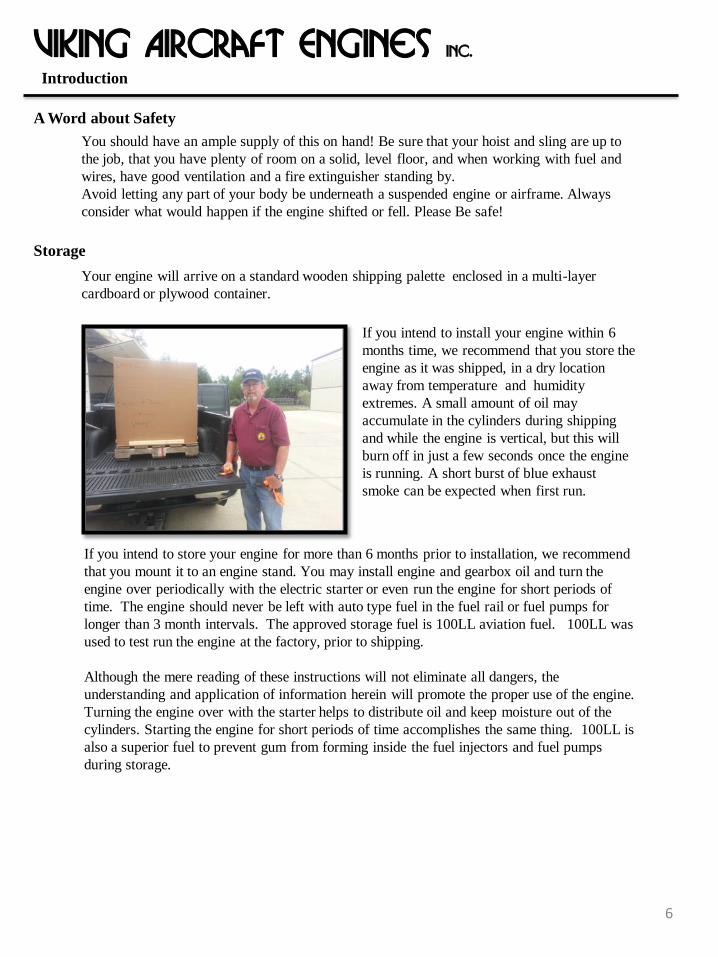
Your engine will arrive on a standard wooden shipping palette enclosed in a multi-layer
cardboard or plywood container.
If you intend to install your engine within 6
months time, we recommend that you store the
engine as it was shipped, in a dry location
away from temperature and humidity
extremes. A small amount of oil may
accumulate in the cylinders during shipping
and while the engine is vertical, but this will
burn off in just a few seconds once the engine
is running. A short burst of blue exhaust
smoke can be expected when first run.
If you intend to store your engine for more than 6 months prior to installation, we recommend
that you mount it to an engine stand. You may install engine and gearbox oil and turn the
engine over periodically with the electric starter or even run the engine for short periods of
time. The engine should never be left with auto type fuel in the fuel rail or fuel pumps for
longer than 3 month intervals. The approved storage fuel is 100LL aviation fuel. 100LL was
used to test run the engine at the factory, prior to shipping.
Although the mere reading of these instructions will not eliminate all dangers, the
understanding and application of information herein will promote the proper use of the engine.
Turning the engine over with the starter helps to distribute oil and keep moisture out of the
cylinders. Starting the engine for short periods of time accomplishes the same thing. 100LL is
also a superior fuel to prevent gum from forming inside the fuel injectors and fuel pumps
during storage.

1500cc Inline 4cyl, 110 hp, Liquid cooled, naturally aspirated,
reciprocating and geared /spark ignited combustion Aircraft Engine
7
Specifications
Viking Aircraft Engines inc.
Type of Engine

Weights
Basic Viking Engine Dry Weight 175 lbs. 79.4 kg
Radiator 7 lbs. 3.2 kg
Fuel Pumps 3.5 lbs. 1.6 kg
Exhaust system 2 lbs. 0.9 kg
Oil Cooler Assembly 5 lbs 2.3 kg
Basic Viking Engine Dry Weight Includes:
1. Geared starter and flywheel
2. Reduction gearing
3. 40 amp alternator
4. Air and oil filters
8
Viking Aircraft Engines inc.
Specifications

Operating Limits2 Level Flight Min Max
Engine speed (RPM) 4800 1700 5800
Manifold pressure 8inhg 27kpa 29inhg 100kpa
Gearbox temp 220 F 105 C ambient
240F 115C
Coolant temp 220 F
93.3 C ambient
240F
115C
Oil temp 220 F
93.3 C 40 F 4.4C 240F
115C
Voltage 14.2V 13.4V 15V
Standby battery (Not charged from alt.)
12.8V
14V
O2 wide band sensor (Air to fuel ratio)
13.8 12 14.5
Oil pressure 60psi 4bar 30psi 2bar 100psi 7bar
Fuel Pressure 43psi 3bar 40psi 2.8bar 46psi 3.2bar
Fuel flow 5.5GPH 20LPH 0.5GPH 2LPH 10GPH 40LPH
9
Viking Aircraft Engines inc.
Specifications

Engine serial number is located on bottom aft part of the engine
Use this number to order parts from Honda.
Your engine block is from a 2009 to 2013 Honda Fit / Jazz car. Use this information when
you buy your engine manual and engine parts from a local Honda Dealer.
10
Viking Aircraft Engines inc.
Specifications
Engine Serial Number

Note: All measurements in brackets are millimeter all other measurements are standard inch
11
Viking Aircraft Engines inc.
Specifications
Dimensions
Front View

Side View
Note: All measurements in brackets are millimeter all other measurements are standard inch
12
Viking Aircraft Engines inc.
Specifications
Dimensions

Center of Gravity From Prop Flange
Note: All measurements in brackets are millimeter all other measurements are standard inch
13
Viking Aircraft Engines inc.
Specifications
Dimensions
Top View

Rear View
Dimensions between mounting positions
14
Viking Aircraft Engines inc.
Top and bottom dimensions are the same
Dimensions are same right to left
Specifications
Dimensions
Note: All measurements in brackets are millimeter all other measurements are standard inch

Prop Flange and Chain Cover View
Note: All measurements in brackets are millimeter all other measurements are standard inch
15
Viking Aircraft Engines inc.
Specifications
Dimensions

Viking Aircraft Engines
16
Specifications
Naming of Attached Components

Viking Aircraft Engines
Radiator
Radiator Air Shroud
Gear Box
Oil Cooler
Coolant By-Pass
Thermostat
Radiator Mounts
Ignition Coil
Intake Manifold Air Filter
Propeller Hub
Muffler
Fly Wheel
Ring Gear
17
Specifications
Naming of Attached Components

Viking Aircraft Engines
Radiator
Radiator Air Shroud
Gear Box Standoffs
Valve Cover
Thermostat
Radiator Mounts
Engine Mount
Fuel Rail
Oil Tank
Muffler
Silicone Hose Coupling
Propeller Nut
18
Specifications
Naming of Attached Components

Viking Aircraft Engines
Oil Cooler Hoses
Radiator Return Tube
Coolant Pump Pulley
Serpentine Belt Throttle Cable
Coolant Bypass Tube
Fuel Rail
Idler Pulley
Oil Sensor Adapter
Throttle Body
Coolant Tank
Alternator Pulley
Oil / Breather Cap
Oil Cooler Shroud
Starter
Air Filter
Intake Manifold
19
Specifications
Naming of Attached Components

Viking Aircraft Engines
Oil Pick Up Tube
Oil Cooler Mounting
Intake Manifold
Oil / Breather Cap
Ring Gear
Oil Drain Plug
Coolant Return Tube
Dampener Assembly
Alternator
Coolant Fill Plug
Serpentine Belt
Crank Shaft Pulley
Radiator Mounting Bracket
Gear Box
Oil Filter
20
Specifications
Naming of Attached Components

Viking Aircraft Engines
Muffler
Crank Shaft Pulley
Coolant Pump Pulley
Idler Pulley Alternator Pulley
Engine Mounts
Engine Mounts
21
Specifications
Naming of Attached Components

Viking Aircraft Engines
Muffler
Honda identification number
Ignition Coils
Oil Drain Plug
Grounding Bosses
22
Specifications
Naming of Attached Components

Viking Aircraft Engines
Gear Box Part Number: 1051015
23
Specifications

Viking Aircraft Engines
24
See prop nut Install procedure
120 in-lbs
120 in-lbs
500 in-lbs
NPT fittings Hand tight plus Half turn with Allen wrench
120 in-lbs
500 in-lbs
500in-lbs
See video on line http://www.youtube.com/watch?v=aWkH-uZIh8Q
Place Blue Loctite on all fasteners with exception to lock nuts
120 in-lbs
120 in-lbs
Alignment pins
Gear Box Part Number: 1051015
Specifications

Viking Aircraft Engines
Short and no lock nut
Short
Short Cap Screw used in all locations with the exception as indicated
25
Threaded into engine and need Blue Loctite
Gear Box Part Number: 1051015
Specifications

Viking Aircraft Engines
26
Air Intake Part Number: 123912
Specifications

Viking Aircraft Engines
27
Air Intake Part Number: 123912
120 in-lbs
120 in-lbs
20 in-lbs
120 in-lbs
200 in-lbs
Place Blue Loctite on all fasteners with exception to lock nuts
Specifications

Viking Aircraft Engines
28
After inserting shaft, place throttle body plate through the slot of the throttle shaft
Air Intake Part Number: 123912
Specifications
Viking Aircraft Engines
29
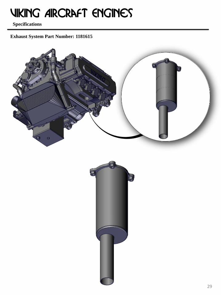
Exhaust System Part Number: 1181615
Specifications
29

Viking Aircraft Engines
30
Note: The muffler was designed with a long tail pipe to be cut to length for multiple installations. (See section for cutting muffler)
Exhaust System Part Number: 1181615
200 in-lbs Studs on engine
Specifications

Viking Aircraft Engines
31
Oil Cooler Part Number: 1181615
Specifications

Viking Aircraft Engines
32
Oil Cooler Part Number: 1181615
Specifications
Same fasteners both sides with bracket
Same fasteners both sides with bracket

Viking Aircraft Engines
33
Radiator
Specifications

This chapter covers the preparation of the airframe to receive the engine and the mechanical
process of installing the engine.
Required Tools, Equipment, and Supplies
• Engine Hoist or Fork Lift
• Strong Nylon Tow Strap or four HEAVY DUTY Ratcheting Tie-Down Straps.
• Portable Electric Drill with assorted drill bits.
• Engine (to firewall) Mount Bolts, Washers, Castle Nuts and Cotter Pins (not
supplied).
• Appropriate tools for cutting a large (approx 2” diameter) hole in your firewall, such as a hole-saw, nibbler and rat tail file.
• General hand-tools to tighten engine mount bolts, etc.
General Sequence of Events A good approach to consider is hanging the engine in place long enough to take measurements and make markings, then remove it, cut and drill all the holes, then reinstall it. It sounds like more work, but it is actually not that difficult, and it requires fewer specialized tools.
Because of the wide variations of airframes and configurations, it is impossible for the factory to provide all of the location details for fuel lines and electrical wiring in advance.
Viking Aircraft Engines CHAPTER 1: MECHANICAL INSTALLATION
Positioning the Airframe
The airframe should be supported on a smooth concrete or paved floor. The firewall should be positioned perpendicular to the floor. For tail-dragger airframes, this requires that the tail be raised and supported by an appropriate means such as a saw-horse, then secured. BEWARE: The airframe will have a strong tendency to tip nose-down once the weight of the engine is on the firewall. For nose-wheel types, this weight can be supported by the nose gear, but for tail-wheel aircraft, the tail must be adequately tied down to something with enough weight to counterbalance the engine. The effects of suddenly adding several hundred pounds to your airframe can be unexpected, dangerous, and costly. Leave yourself plenty of room to the front and sides to maneuver an engine hoist and try to locate a spot where the floor is solid and level underneath the engine. If engine mount bolts came with your airframe kit, it is almost certain that they will not fit this
engine mount! Carefully measure the bolt lengths required for all engine mount bolts and pre-
order these parts. Use only AN standard high-quality bolts with washers, castle-nuts, and cotter
pins. (Experimental aircraft often use nylon insert nuts without any problems)
Installation
34

ALL MOUNT LOCATIONS ON CHAIN COVER
LIFT POINTS
Viking Aircraft Engines
STANDOFF FOR GEAR REDUCTION
CHAPTER 1: MECHANICAL INSTALLATION
Lifting the Engine
35

THESE LOCATIONS NEED SPECIAL ATTENTION! THESE ARE AREAS THAT IF BUMPED WHEN LIFTING CAN DAMAGE THE ENGINE.
PULLEYS
AIR INTAKE
MUFFLER
RADIATOR
SHROUD
PROP HUB
OIL COOLER
COOLANT TANK AND LINES
WIRE HARNESS AND HOSES
FUEL RAIL
Viking Aircraft Engines CHAPTER 1: MECHANICAL INSTALLATION
Lifting the Engine
36

Install the engine mount to the engine, using the suplied rubber dampers, large area washers, smaller washers and nylon insert locking nuts. Use a large area washer on each side of the rubber assembly combined with smaller AN-970 washers outside of these. The bolt can go in either direction, depending on what is easier for your particular installation. Snug all fasteners and mark them as being loose. Raise the hoist to the height required to install the engine and slowly roll it into position. Review the videos for actual footage, showing this procedure in action. Align the mount with the firewall holes (if already drilled). The engine mounting structure is somewhat flexible and some pushing is allowed. If slight reshaping of the weldment is needed for alignment, use a ratchet strap to pull beyond the ideal location, then release. Repeat until perfect. Be sure to leave the engine mount loose on the engine to allow for easier positioning.
Adjust the level of the engine or airframe as needed to mate the engine mount to the firewall. When you are satisfied with the alignment of the engine mount, mark the centers of each bolt hole (If firewall is not already drilled)
Determine and mark where the fuel supply line need to be located on the firewall.
Pay attention to internal structure inside the cabin. Avoid sharp bends in the fuel lines and route
them far away from sources of heat or chaffing. Be sure to leave enough space for the high
pressure fuel filter.
Locate and mark the desired position for the bundle of wires to penetrate the firewall. The wire
bundle will fall into a ‘natural’ position somewhere near the upper pilot side of the firewall,
however, pay attention to where the throttle cable and coolant reservoir will need to be. The wire
bundle location is more flexible than some of these other items.
Locate and mark where the coolant reservoir will be located. The Viking use a siphon system so
the tank can be below the engine, if needed.
If you are installing a cabin heater, locate and mark where the heater hoses will mate up with the
heater fittings.
Locate and mark where the throttle cable will penetrate the firewall. This will be obvious based
on the angle of the clamp on the intake manifold. Most builders prefer to use a small stainless-
steel “eyeball” fitting to protect the throttle cable as it passes through the firewall. These are
available through most aircraft parts suppliers. A good swivel-eye type bulkhead fitting is
Aircraft Spruce's p/n SE961-188B (0.188" dia.).
Viking Aircraft Engines CHAPTER 1: MECHANICAL INSTALLATION
Positioning and Marking the Engine Mount
37

16
Finally, consider any other firewall mounted equipment such as brake fluid reservoir before
finalizing your marks. Once everything has been marked, remove the engine and return it to a
safe position.
If you are not confident in the precision of your marks, you may want to drill the holes slightly undersized, and then finalize them by drilling THROUGH the engine mount bushings once the mount is again raised into position. This might require a LONG drill bit and possibly a 90- degree drill. Drill the fuel line bulkhead fitting holes. Drill mounting holes for the coolant reservoir Cut the opening for the bundle of wiring to pass through into the cabin. This can be done with a large hole-saw or a nibbler or just a ring of smaller holes cleaned up with a rat tail file. The size of this opening must accommodate the connector that attach to your engine control unit (ECU). Consider how you wish to seal up this opening once the bundle has been installed. Aircraft part vendors also offer a variety of firewall fittings to serve this purpose and Viking has a Nylon Pass Through item in their Shopping cart. On the following page are some photos showing how to install a nylon bulkhead seal. (In fact, parts mentioned throughout this guide are all located in the Viking “Grab Bag” product.
Viking Aircraft Engines CHAPTER 1: MECHANICAL INSTALLATION
Positioning and Marking the Engine Mount
Drilling the Engine Mount Bolt Holes

A picture is worth a thousand words, so here’s the whole sequence in
pictures.
TIP: If your airframe vendor provided you with a nice piece of stainless-steel
for a firewall, POLISH IT NOW. Nothing looks better or is easier to keep clean
than a piece of highly polished stainless steel. A few minutes of elbow grease now will make for years of pride when showing off your powerplant. “Never
Dull” polishing wool or a tube of “Semichrome” polish works well.
A nice firewall pass- through example.
Aircraft Spruce p/n NMCS45A-11,
Grommet p/n AN931- 11-16 (you need 2 grommets)
17
Viking Aircraft Engines CHAPTER 1: MECHANICAL INSTALLATION
Positioning and Marking the Engine Mount

15
Place a washer under the head of the two bottom-outer engine mount bolts and insert the pair of bolts from the inside of the airframe cabin protruding out through the firewall. Some duct tape helps to hold the bolts in place if they are easily moved. Raise the powerplant into position again. Position the engine mount so that these lower two bolts slide into place through the mount. Loosely fasten these bolts with a washer and castle nut. Continue positioning the engine mount as needed to align and insert the remaining engine mount bolts. Once all the bolts are in position, tighten the nuts to their proper torque (refer to your manufacturers specifications or the Standard Aircraft Handbook) and insert the cotter pins. Slowly lower the engine hoist. Pay attention to what the tail and gear legs are doing! Adjust or prop things up to prevent damage. You may want to take the time to install your wheels and tires before lowering the now-heavier airframe. If the fuselage tips easily, you may want to leave the hoist attached a while longer as you finish the installation. Often the empennage must be installed before tail weight is sufficient to prevent tipping. If things are solid, go ahead and remove the hoist and straps. IMPORTANT - Verify that the engine has the same angle as indicated in your aircraft manual. Most engines are level with the longitudinal axis, or have a slight down angle towards the front. Some engines have the front tilt sideways towards the pilot side of the aircraft to accomodate for torque and P-factor. Your manual might indicate this in the opposite direction, showing an engine that turn in the opposite way. Take a break and admire your project!
Viking Aircraft Engines
Attaching the Engine
CHAPTER 1: MECHANICAL INSTALLATION

Viking Aircraft Engines
Torque Specs:
41
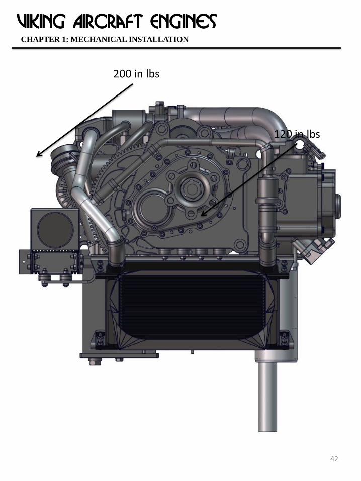
6mm - 120 inch pounds
8mm - 200 inch pounds
CHAPTER 1: MECHANICAL INSTALLATION
Viking Aircraft Engines
120 in lbs
42
200 in lbs
CHAPTER 1: MECHANICAL INSTALLATION

Viking Aircraft Engines
43
200 in lbs
CHAPTER 1: MECHANICAL INSTALLATION

Viking Aircraft Engines
44
200 in lbs
CHAPTER 1: MECHANICAL INSTALLATION

Viking Aircraft Engines
45
CHAPTER 1: MECHANICAL INSTALLATION

Viking Aircraft Engines
46
CHAPTER 1: MECHANICAL INSTALLATION

Viking Aircraft Engines
47
This chapter covers the installation of engine related plumbing, focusing on firewall- forward, but
also describing the related “Airframe Plumbing” in a later section with the same title.
“Plumbing” includes all fuel, coolant, vents, and air duct installation.
CAUTION: Use extreme care when installing barbed fittings into flexible hose so as to avoid
cutting small shards of material inside the hose. More than a few new aircraft have failed due to
fuel hose debris in the fuel lines.
TIP: We highly recommend the use of Oetiker clamps (as found everywhere else on our
powerplants) or “fuel injection” type screw clamps. NEVER use automotive worm- drive screw
clamps as these will ultimately damage your hoses and come loose.
Your engine requires what is known as a “RETURN” fuel system. Fuel injected engines require
a continuous supply of high-pressure fuel to the injectors. In order to provide this fuel supply
and to eliminate concern for “vapor lock”, your powerplant uses a fuel system where cold fuel
is continuously pumped through a loop that passes each fuel pump and any excess fuel that is not
consumed by the engine is returned to the same fuel tank it was sourced from.
Never construct the fuel system such that ANY low pressure fuel is exposed to the heat of the
engine compartment. This will cause the fuel to boil.
The following is a useful diagram of the full loop fuel system. Become familiar with this diagram
for installation, maintenance and operational reasons. Consider making this diagram a part of
your Pilots and Owners Handbook.
CHAPTER 2: PLUMBING INSTALLATION
Attaching the Fuel Lines

Viking Aircraft Engines
48
Introduction
Fuel pressure is regulated by a Fuel Pressure Regulator. This regulator is set to the proper 43psi.
The regulator has a small hose nipple present. Leave this open to the atmosphere. The fuel
selector valve, is replaced by a header tank, on most high winged aircraft systems.
We will cover the airframe side of the fuel system installation a little later. For now, we are
only interested in connecting the engine side of the fuel system to the firewall bulkhead
fittings. Install the bulkhead fitting and the 2 fuel nipples shown in the picture, through the drilled
hole in the firewall. Use LockTite 567 sealer on all pipe threads.

Viking Aircraft Engines
49
Introduction
Install a high pressure fuel filter in the supply line to the engine. The recomended filter is in the
Viking online shopping cart. Be sure to mount it such that the flow is in the correct direction, as
marked on the filter and that the proper clamps and fuel injection hose is used.
You will be using “Fuel Injection” hose. This is high-pressure hose. Never replace this
hose with any type not rated for high-pressure fuel injection use.
The Viking engine uses 5/16” (8mm) inside diameter hose. This equates to AN-5 fittings. These
fittings are somewhat uncommon, but available through good aircraft part suppliers. Spruce /
Wicks.
1. Having measured, marked, and drilled holes for your supply fuel line. Install the firewall
fuel through fitting.
2. Protect the exposed fuel supply line with fire-sleeve or a section of high
temperature flexible conduit.
3. Terminate the hose from the through fitting at the fuel filter, then from the filter to the
optional fuel flow transducer, then onto the engine fuel rail. O-ring type grease (see
shopping cart) is used on every hose connection. For the hose terminating on the engine
fuel rail, add the clamp to the fuel rail first, then lube the rail barb area and with a steady
push, engage the hose onto the rail and all the way up to the second barb. Secure with a
14.2mm Oetiker clamp between the two barbs. If this connection is tough, go buy a
fresh section of fuel injection hose, add the lubrication to the rail and heat the hose in
hot water, the push on.
Fuel Supply Line & Filter

Viking Aircraft Engines
50
Introduction
If you are installing a cabin heater option, you can go ahead and install the heater unit now,
or skip this section and return to it later on. When the heater has been installed in the cabin, a
pair of barbs will protrude through the firewall to make the heater hose connections.
The barbed fitting, opposite to the Fuel Pressure Regulator, is for the fuel return line.
• Protect the exposed fuel return line with a section of high temperature
flexible conduit.
• Attach the fuel return line with a 14.5mm Oetiker clamp.
Fuel Return
Attaching the Coolant Hoses

Viking Aircraft Engines
51
Introduction
Your engine comes with an open style cooling system. Conventional automobile systems
pressurize the cooling system to 20psi or greater to raise the boiling point of the coolant. Because
our powerplants do not use water or conventional antifreeze, we have no need to pressurize the
system. Our NPG+ coolant has a boiling point of 375F. Far above what your engine will ever
reach. Since it is not necessary to run pressure, fatigue on hoses, clamps, gaskets, etc. is
minimized. Never use any coolant other than NPG+.
Route and secure the engine breather tube. From the engine oil cap / breather filter, attach a oil
resistant (see Viking shopping cart) 5/8 (16mm) ID hose and run it overboard. Alternatively,
terminate the hose in a plastic container, then exit the container overboard, with another hose of
the same internal diameter. The later installation method will catch any small amount of oil and
keep the belly of the airplane clean. 2015 engines also use a second breather hose from the valve
cover side of the engine. The more crankcase breathing, the better.
Engine Breather Tube
Coolant Pressure

Viking Aircraft Engines
52
Introduction
In this section we will examine the plumbing of the airframe itself.
Most conventional aircraft have two fuel tanks, one in each wing. Some have additional header
tanks (typically a smaller tank to collect fuel at a level closer to the engine) and auxiliary
tanks. We will not get into plumbing of auxiliary tanks, but we will mention the proper way to
implement a header tank as some of our customers will be required to use these.
If you have been reading the prior sections, you’ll understand that our fuel system requires a
continuous flowing “loop” of fuel between the aircrafts fuel tank, the fuel pumps, and back to the
tank again. The fuel in this loop is held at a controlled pressure of 43psi by a fuel regulator and
the engine injects only a small portion of the total volume of fuel that passes through this loop.
Approximately 35 gallons per hour move through the loop.
This system assures a steady and ample supply of relatively cold fuel, cools the fuel pump and
helps to sweep away any vapor bubbles that may develop in the system.
To accomplish this loop system, the airframe requires some additional plumbing that is not
typically found on gravity feed systems.
First, the tank supplying the fuel must also be the tank we return unused fuel to, otherwise
we would shortly transfer all our fuel and overflow the return side tank or run the supply side
tank empty! I know what you’re thinking, but please don’t get “creative” with this. It is far too
easy to make a mistake and find your fuel has gone somewhere you didn’t intend. You want to
end up with what works like a "conventional" fuel system.
To guarantee that the supply tank is also the return tank, we use a 6-port fuel selector valve.
(Unless you use a header tank system - more later about this) This valve has two distinct valve
segments (spools), one for supply lines and one for return lines. When you select a tank, you
select it for both supply and return. Thus two ports connect to each tank (a supply and a
return) and the remaining two ports go to the engine (also a supply and return).
Secondly, each fuel tank must be fitted with a return line. Because the engine will
consume some of the fuel, and is not in a gravity feed system, the return line can be slightly
smaller than the supply line, or it can be the same size if you prefer.
AIRFRAME PLUMBING

Viking Aircraft Engines
53
Introduction
For the airframe supply lines, we require the use of 3/8” ID aluminum fuel tubing and AN-6
fittings, up to the selector valve. For the airframe return lines we recommend the use of 1/4”
ID aluminum tubing and AN-4 fittings, however you can also use the larger lines for return if
you want to keep all of your plumbing consistent. The return lines run from the 6-port selector valve to each fuel tank. At the fuel tanks, this
return line is typically connected to a bulkhead fitting in the side of the tank access panel or
end panel.
The 6-port fuel (Viking Shopping Cart) valve is to be located as close to the floor of the fuselage
as possible to avoid having to pump fuel up-hill. Many of the popular kit planes provide a
perfect spot for the Valve.
Below is an example of a good valve installation. Notice the smooth bends with large bend
radius. These bends were made with a $20 tubing bender purchased at a local home building store
(and a little practice). Never settle for dented or twisted tubes! Tubing is inexpensive compared to
tubing failures. Aircraft Spruce sell soft, coiled "Versatubing" that is much easier to work than
rigid tubing. Expect to scrap several pieces before you get the feel for this process. The flare
fittings are 37-degree flares made with a quality aircraft flaring tool. These tools cost approx
$100 but are a good investment.
Words of wisdom; wherever possible, install the flare nut and make the flared end before
bending the tube and always remember to put the sleeve and nut onto the tube before flaring the
tube! You’ll see….
This is a 6-port valve installed in the center
console.
Fuel Valve Installation

Viking Aircraft Engines
54
Introduction
In the above photo, you can see the pairs of tubes coming in from the left and right tanks and the
center pair of tubes heading forward to the engine. The upper tubes are all 3/8” supply lines,
while the lower tubes are 1/4” return lines.
Be sure that all of your flared ends seat squarely on their fittings. Never allow a flare nut to pull
the tube into place! This creates strain on the flared fitting that can result in a future crack
and leak. If a tube doesn’t sit squarely on its fitting, bend it some more or make another tube
that does fit. Never use Teflon thread tape or other sealants on flared fittings. Always consider what will happen if a fuel line, valve, filter, or other component should spring
a leak inside your cabin! It is a very simple task to make a barrier around areas that house fuel
components and provide a drain and vent system. Below is a simple example of how this can be
done.
This floor drain is nothing more
than a hole drilled through the
bottom skin with a small section of
stainless-steel mesh to keep insects
out.
In the event of a fuel leak, this will
prevent fuel from spreading
through the cabin.
A similar vent hole allows fresh
air to circulate in the fuel area.
Installing a Cabin Floor Drain

Viking Aircraft Engines
55
Introduction
Fuel flows from the fuel tanks into the selector valve then through the low-pressure filters and into
the pumps. The pump outputs tee together inside the supplied "fuel manifold" and a single line
runs forward to the firewall, through a high-pressure filter, then to the fuel rail. The pressure
regulator is shown in the fuel manifold and the return fitting has tape and is pointed back
towards the fuel pumps. In this area of the fuel system, all diameters are 5/16” (8mm)
The electric pumps each require a power wire and a ground wire. The polarity of the wires is
marked on the pump terminals. For obvious reasons, you want to make very solid, reliable,
electrical connections to fuel pumps and route the wiring away from the pumps as directly as
possible. Pumps normally draw between 4 (unloaded) and 7 (restricted) amps of electrical
current, so be sure to use a suitable gauge wire for both power and ground connections. This is
also dependent on the length of the wire, but typically these will be between 18 and 16 gauge
wire.
The pumps themselves should be mounted to the floor of the aircraft cabin or a suitable sub-floor
bracket. It is important to mount the pumps as low as practical to improve their ability to prime
themselves and to restrict potential fuel leaks to the floor area. The pumps come from Viking
with simple brackets and rubber cushion clamps that will allow you to make a suitable
installation.
Finally, the fuel pumps make a noticeable whining sound when running. When closed into a
console or floor panel, the sound will not be noticeable over the engine and propeller sound. It is
reassuring to be able to hear the pumps during engine startup.
The dual fuel pumps and low-pressure filters are typically plumbed together with flexible fuel
injection hose when they arrive from the factory.
Fuel Pump Installation

Viking Aircraft Engines
56
Introduction
Several filters are required in your fuel system. Let’s review each one.
1. Typically, each fuel tank pickup tube will have some form of screen over it to avoid
becoming blocked by large debris that may fall into the tanks while fueling.
2. Prior to the pump inlets a low-pressure/high-volume fuel filter is required to capture
particles that may block internal passages within the pump or cause premature failure of
the pump. These are typically 100 micron filter elements. Because the fuel at this point is
not yet pressurized, these filters need only be able to handle the volume of fuel that
passes through them, approximately 35 gallons per hour.
3. These low-pressure filters should be replaced shortly after your first flight since that is
when a lot of construction debris is present and then during each annual inspection.
Because they will be serviced often, give some thought to their accessibility and capture
or draining of the fuel that will inevitably leak during filter changes. Replace any short
rubber hose sections each time you replace filters. Use smooth fuel-injection type screw
clamps or Oetiker clamps. (Due to the low pressure in this area, it is allowable to use
spring clamps for these filters only. They are usually suplied with the filter and make for
easy changing. However, always use fuel injection hose, not the supplied hose that also
might come with these filters)
4. Internal to each fuel pump is a small check-valve and another screen. These are fairly
coarse screens only intended to protect the check valves. They are not serviceable. The
check-valves prevent one pump from pushing fuel back through the other non-running
pump and prevent bleed pressure losses in the fuel system.
5. After leaving the fuel pumps, pressurized fuel is routed through the firewall bulkhead
fitting and then to a high-pressure/high-volume filter. This filter is typically a 70 micron
filter element. This filter must be able to handle at least 60 psi pressure and 12 gallons
per hour flow. This is typical of a “fuel-injection” type filter. You can purchase these
from Viking.
Filters, Strainers, Screens, and Gascolators

Viking Aircraft Engines
57
Introduction
6. Leaving the high-pressure filter, fuel is routed through an optional fuel flow transducer,
(not required for fuel flow with the Viking View) then to the fuel injector rail. Each fuel
injector has an extremely fine mesh screen inside it. This is the last point of filtration.
Occasionally we find fuel injectors that are clogged or stuck, usually due to stale fuel that
has gummed up the works. You can remove the injector rails, being careful not to lose or
damage the o-ring seals, and clean the injector screens with spray carburetor cleaner. If the
injector is stuck, you can take them to an automotive repair shop equipped to clean injectors
or you can purchase new injectors.
7. The fuel pressure regulator has its own internal screen to protect its valve. If the pressure
regulator fails, it must be replaced.
Gascolators are not very effective in full loop fuel systems due to the sheer volume of fuel
flowing through them. Any water that may be trapped in a gascolator is quickly swept up into
the flow again. Gascolators do provide a coarse screen filter, but that’s about their only real
benefit in our system. There is a real danger in the gascolator not being reliable on the high
pressure side and causing possible cavitation, through an O-ring leak, if used on the low pressure
side of the fuel system. Any leak on the high pressure side is bad. Any leak on the suction side is
bad.
Water drainage should be accomplished with sump drains in the gas tanks and header tank. A
warning to die-hard gascolator fans. If you use a spring “poppet” type drain valve in a
gascolator, it is entirely possible that the pumps will draw air INTO the system through
these drain valves! A tiny tear in an o-ring or a piece of dirt under the o-ring seat results in a
path of least resistance for air. Always use a positive seating drain valve such as a needle valve.
Gascolators & Water Drains

Viking Aircraft Engines
58
Introduction
The "return" type fuel system must ultimately return unused fuel to the fuel tanks (or tank, if using
a header tank) This requires the installation of a second fuel line between the fuel selector valve
and a bulkhead fitting for each fuel tank (high- wing aircraft builders, read the next topic too).
This photo shows a
typical aircraft fuel
tank with an
additional bulkhead
fitting installed in the
access plate for the
fuel return line (“R”).
The other two are the
supply line (“S”) and
vent (“V”).
The return line can
also go on the rib
instead of the access
plate if that is simpler
to construct.
Inside view of a
typical fuel tank
access panel. Be sure the return
line does not interfere
with the fuel quantity
float.
Fuel Return Line

Viking Aircraft Engines
59
Introduction
While on the subject of fuel systems, we have learned from experience that “capacitive” type
fuel senders are undesirable for aircraft that can use both 100LL and automotive fuels due to the
difference in dielectric properties of these fuels. The variation in quantity indication can be as
high as 10% and is unpredictable when the two fuels are mixed. A good old-fashioned float
type sender will treat you better and doesn’t care what fuel is in the tank. Even better is a direct
reading system if you can make it happen.
High wing aircraft have an advantage over low wing aircraft in that they can use gravity to
assist with fuel flow. However, they are also subject to a different set of problems than most
low wing aircraft. Some of the more common high wing kit planes have folding wings, fiberglass
tanks, very tight space around the fuel tank root panels, and problems with un-porting fuel
pickup tubes in certain flight attitudes. For this reason, the manufacturers have implemented
small “header tanks” in the door columns or behind the seats. These headers were intended to
act as accumulators for enough fuel to ride through a temporarily un-ported tank.
Fuel Quantity Senders
High Wingers and Header Tanks

Viking Aircraft Engines
60
Introduction
The solution is to provide a “common header tank” Each wing will supply fuel to this common
header tank and the engine will draw fuel from this tank alone and return fuel to this tank
alone. If the aircraft is equipped with small door column header tanks, these can be left as-is,
upstream of the common header tank, or they can be removed as they really serve no purpose
that the common header tank can’t fulfill.
The common header tank must be a minimum of 2.0 gallon capacity.
This is essential to allow the warm, vaporous, return fuel to cool down and disperse vapor bubbles
before being drawn back into the supply line.
Since this common header tank is the sole source of and the fuel pumps will not flow fuel if off,
any fuel valves are only used for servicing the aircraft. Be aware that every valve has a
potential for being left off, and a potential to leak.
We have flown several header tank installations without a designated vent line to the header tank.
However, this needs to be verified and a fuel drain test should be done before flight. Normally, if
the wing tanks are properly vented, air will escape the header tank through these vents. It is
important to run large fuel lines in the gravity part of the fuel system. Our “Fuel System in a
Box” header tank has an additional port for a vent line going back up to at least one tank. Finally, since the common header tank is the lowest fuel source in the aircraft, it is the
obvious good place to locate a fuel gauge as well as a sump drain valve. Knowing that you have
20 minutes left of fuel can help you one day.

Viking Aircraft Engines
61
Introduction
Example of a Fuel Line Layout with Header Tank (This one with separate vents)
Excellent example of a Common Header Tank for High-Wing Aircraft
Universal header tanks are available from Viking in the online shopping cart. Look
for “Fuel System in a Box”

Viking Aircraft Engines
62
This chapter covers the installation of all cables and wiring required to operate the powerplant.
This is the ONLY aproved wiring for all engines and earler models should be updated to this dual battery system. If you are not comfortable performing wiring related tasks, you must seek assistance from
someone who is. You will need a rock-solid electrical system, so this is not the place to take
risks.
Various sensors are located on the engine for monitoring temperature and pressures. If you
ordered your powerplant along with an engine monitor, then your sensors will be pre-installed.
You are required to connect the engine monitor wiring harness to these sensors following the
instructions provided by the vendor.
If you did not order an engine monitor, you will need to obtain and install your own set of sensors
for at least, the following items.
• Oil Temperature
• Oil Pressure
• Coolant Temperature
• Gearbox Temperature
• Fuel Pressure
• Battery Voltage (2)
A pictorial guide to the engine sensor locations is provided on the Viking web site Your powerplant is a technically advanced design which depends on a computer and a variety
of electronic sensors to control operation of its ignition and fuel injection system. This is
fundamentally different from traditional aircraft engines which generate spark from mechanical
magnetos. One can argue the merits of mechanical versus electronic controls endlessly;
however, the type of electronic system your powerplant uses has evolved over decades of use in
millions of vehicles. The Viking use a redundant ECU in its operation.
CHAPTER 3: ELECTRICAL INSTALLATION
Engine Sensors
General Electrical Strategy & Requirements

Viking Aircraft Engines
63
The use of modern electronics provides a very precise control over fuel mixture and ignition
timing, responding instantly to changing conditions.
The Achilles heel of any electronic engine control system is its fundamental requirement for a
rock-solid electrical supply. A battery alone meets this requirement perfectly. However, batteries
live only so long before they need to be recharged.
Introducing an Alternator and voltage regulator into the picture creates a far more complex and
somewhat electrically noisy environment and also the need to monitor for, and respond to,
additional failure modes. Monitoring failure modes requires instrumentation and responding
to failure modes requires switches. Our once- simple battery has grown into quite an assortment
of devices, each contributing to the overall failure rate.
When flying an airplane, a pilot gets accustomed to the sound of the engine. When this sound
falls silent, most pilots would agree that their ability to quickly and clearly perform failure
analysis and formulate a response is somewhat limited by their interest in the soil passing below
their seat.
So why not just plug in a fresh battery and leave everything else turned off? Brilliant!
1. Requirement – The electrical system must have dual batteries, each capable of
operating the powerplant for at least 30 minutes of flight at cruise power, with only the
essential equipment required to operate the engine.
2. Requirement – A means of selecting one, the other, or both batteries.
3. Requirement – A means of turning off all but the essential equipment required to keep
the engine running.
4. Requirement – A means of monitoring the charge state of each battery.
Hot Standby Battery; Switched on demand.
This strategy simply keeps a spare battery standing by until it is needed. It is then switched into
service to replace the primary battery. The charging requirement can simply be met by flying
different legs on a different battery, thereby constantly keeping them charged and ready. This is
the system used by Viking.
CHAPTER 3: ELECTRICAL INSTALLATION

Viking Aircraft Engines
64
CHAPTER 3: ELECTRICAL INSTALLATION
Positive Side: 1) Install a #6 cable from each battery positive to the BAT side of each contactor. 2) Install a #6 cable between one contactor output and the starter 3) Install a #8 cable between one contactor output and alternator terminal, through a 60A fuse. Alternatively, install a #10 cable between the alternator fuse output and the starter terminal. This would be a shorter cable in most installations and can handle the alternator output. In this case, the 60A fuse is located on the engine, between the alternator and the starter terminal. 4) Install a #6 cable between the two contactor output studs. 5) Connect the #14 wire from the Viking ECU to the output from the contactors 6) Connect starter solenoid (spade terminal on starter) to S terminal of starter switch. Connect B terminal of starter switch to the aircraft power bus through 10A breaker. 7) Connect Alternator Sense wire (the spade terminal of the alternator that form the top of the letter T) to a terminal on the ignition switch that stay on at the first click of the starter key, then is disconnected with the key off. Negative (GND) Side: 1) Install #10 cable between each battery negative terminals 2) Install #10 cable from each battery to airframe ground / Grounding bus 3) Install #6 cable from each battery to engine ground. Be sure to strain relieve cables before leaving engine and battery 4) Install 2 switches to ground on panel for closing of contactor to select battery. Use individual wires to separate grounding studs for safety. 5) Ground the fuel pumps individually directly to the engine to allow for continued operation in case of a main battery wiring disconnect

Viking Aircraft Engines
65
If you haven't done so already, now is the time to acquire a pair of batteries. Several types are
suitable: Viking Use the Earth X brand for their aircraft due to the light weight. Whichever type of batteries you prefer, make sure they have suitable bolt-type connector studs.
During cable installation, tighten the nuts gently, using lock washers and flat washers, to avoid
damaging the battery terminals. Avoid spillable batteries or ones with special venting requirements.
CHAPTER 3: ELECTRICAL INSTALLATION
Batteries
Required Electrical Tools:

Viking Aircraft Engines
66
1. High-quality wire strippers (20AWG through 10AWG) AWG = Average Wire Gauge
or just Gauge for short.
2. Terminal Crimping Pliers
3. A large gauge terminal crimping tool for 8AWG through 4AWG cable ends.
4. A sharp razor knife such as an Exacto knife.
5. A good assortment of shrink-tubing (various sizes and colors, including clear) and an
electric heat gun to shrink it (not shown).
6. A good assortment of tie-wraps.
7. An assortment of Teflon aviation wire and cable. Sizes are denoted as we go, or
refer to the master parts list.
8. An assortment of protective rubber terminal boots (approx. 8 large ones and 12
small ones).
The diagram on the following page illustrates one method of wiring the aircraft which
satisfies our requirements. We have intentionally simplified it to show only the engine-
related circuits with references to where the remaining circuits can be wired in.
This method requires a pair of continuous-duty contactor relays (Master Relays) available
from Aircraft Spruce. ANL-type fuses protect the alternator output cable.
All switches must be high-quality components capable of reliably sourcing 20 Amps per
contact. Please avoid the use of local hardware store parts in your critical electrical system!
Our objective is to provide a reliable network of aircraft quality cables that connect the
dual batteries with the engine ground, firewall grounding buss, the starter motor, the main
Viking Power Bus and the alternator.
CHAPTER 3: ELECTRICAL INSTALLATION
ENGINE WIRING SCHEMATIC DIAGRAM

Viking Aircraft Engines
67
General Notes:
1. Use the diagrams shown on the following page of this manual:
2. Do not use any online available dual battery diagrams.
3. Do not use any overvoltage parts that complicate the system.
4. Use only quality parts from sources like "Air c r a ft Spruce” or buy the Viking “Grab Bag”
5. Replace plastic ties with ADEL loom clamps and conduit for a professional installation
when layout is complete.
6. Use only a ratcheting professional crimping tool. ( Obt a in a larger tool for battery lugs. Do
not solder.)
7 . A really good crimp, made by a good, and right type of pliers, will make a reliable, non brittle
connection.
8. Use shrink tubing on all bare connections.
9. Use only tinned aircraft grade cable.
10. The engine has 10x1.25 and 8x1.25 tapped holes, do NOT use commercial 10x1.5 metric
hardware.
11. Use a thin washer and lock washer / nut to tighten all lugs.
12. Use separate connections for grounding cables in order to have true redundancy.
13. Make sure to get and refer to the installation videos for the approved techniques and
installation methods.
WIRING THE VIKING You must review the YouTube Viking engine installation video series prior to wire your engine. Your objective is to provide a reliable network of aircraft quality cables that connect the dual batteries with the engine ground, firewall grounding buss, the starter motor and the alternator. If you are not familiar with aircraft quality wiring, get help from a certified avionics technician or other qualified individual.
CHAPTER 3: ELECTRICAL INSTALLATION

Viking Aircraft Engines
68
IMPORTANT NOTE: Lithium Ion batteries are superior to the lead acid type in many ways. However, they act
differently. As with your modern power drill, it will continue to operate at full capacity, until suddenly empty.
This is good, since we want max output when needed. However, keep in mind that your alternator charge
should be 13.8 to 14.2V. If you read lower, chances are you are running on battery power alone, and no
charging is taking place. You will not see a gradual reduction in Voltage. Also, the alternator warning circuit
lamp should be wired:
Wire the warning light so that it has 12V to one side when the ignition switch is on.
Wire the other end to the alternator, as shown.
The alternator provide the grounding and will shine the light any time it is not charging.
The grounding is removed with the alternator running / providing a charge.
CHAPTER 3: ELECTRICAL INSTALLATION

Viking Aircraft Engines
69
Electrical Cable Installation
There are several large gauge cables required by your power plant. Each of these cables will
need to attach to the firewall or pass through the firewall into the cabin. You need to protect
these cables from chafing using firewall pass-through fittings or similar fixtures. It is acceptable
to pass these cables through the same opening as the engine wire bundle as long as some
distance between the cables and the rest of the engine wiring can be maintained.
Ground Cables
First, TWO separate ground cables must be constructed and run between the engine block and
firewall. The ideal ground cable installation will utilize TWO sections of 6 AWG cable run
from different locations on the engine block to different bolts on the firewall or grounding plate.
grounding.
Construct and install your two 6AWG ground cables now with the required strain relief. The
following photographs show an example of proper installation.
See DVD for more info.
Starter Cable
Next, your powerplant will need a 6 AWG cable to the starter motor. Your starter motor is a
geared motor containing its own starter solenoid relay. Therefore, no additional starter contactor
relay (such as found in many aircraft) is required. This starter cable runs directly to the main
positive post of the primary battery contactor and remains “hot” with either contactor selected.
This way, either or both battery can start the engine.
CHAPTER 3: ELECTRICAL INSTALLATION

Viking Aircraft Engines
70
The way the above batteries are installed, you obtain a very simple, yet completely dual, battery
system.
• The system provides standby power - when you need it
• Each battery is powering the same main electrical BUS (The Viking Power Module) Each
battery can power the starter and be charged from the alternator
• When contactor 1 is ON - battery 1 is supplying the power
When contactor 1 is ON - battery 1 is being charged
• When contactor 2 is ON - battery 2 is supplying the power
When contactor 2 is ON - battery 2 is being charged
• Due to the extreme lack of discharge from the Lithium batteries, only one battery is
charged / flight.
• Fly your first leg on Bat 1. It will also then be fully charged by the alternator.
• Fly your second leg (or flight home from breakfast), on battery 2. It will also then be
charged by the alternator
• You can use dual batteries and dual fuel pumps for takeoff and landing..
CHAPTER 3: ELECTRICAL INSTALLATION

Viking Aircraft Engines
71
Install your starter cable now. Leave the batteries disconnected until all engine wiring is
finished and we are ready to do a systems check.
Alternator Cable
1. Your Alternator output terminal must have a 8AWG cable (often referred to as a “B-
Lead”) connecting the large screw terminal on the alternator with the battery
charging system.
2. Secure the alternator terminal with a lock-washer and nut. Protect all exposed
terminals with silicone boots.
3. Run an 8AWG cable from the alternator screw terminal to one side of a 60A
circuit breaker or fuse.
Starter Cable & Boot
*Also showing solenoid wire on top.
CHAPTER 3: ELECTRICAL INSTALLATION

Viking Aircraft Engines
72
4. Run a 8AWG cable from the
other side of this circuit breaker
or fuse to the output side of one
battery contactor. (The contactors
will be connected together on the
output side, so ither terminal will
work)
5. The remaining terminal connection
is for an alternator fault light (aka
idiot light). To use this feature,
provide 12 volts to one side of a
small lamp and hook the ground
side of the lamp to this terminal.
The alternator will ground the
terminal if it detects a failure,
thus illuminating the lamp.
CHAPTER 3: ELECTRICAL INSTALLATION
This picture shows the strain relief of
the main alternator cable, before it
leaves the alternator body. The terminal
is protected with a silicone boot and the
alternator sense wire has been installed.
Missing is the "Idiot Light" wire.

Viking Aircraft Engines
73
Mounting the ECU
• Mount the ECU (Engine Control Unit / Computer) in a location that permits
relatively easy access to it as periodic software updates require the unit to be
swapped out.
• Although no explicit cooling is required by the ECU, avoid mounting it near
sources of heat and keep it away from all possible sources of water. Be very careful
NOT to mount it below any windshield or other area subject to leaks.
• It is best to mount the ECU so that its various connectors are facing down or are
otherwise easily accessible.
• Avoid mounting the ECU directly behind or in close proximity to radio stacks and
antennas.
• Secure the ECU using four supplied mounts. Fabricate a bracket if needed.
Engine Wiring Harness Bundle
The main bundle of wires pre-attached to your engine must all pass through an opening in
your firewall and be reattached to the Engine Control Unit (ECU), as well as various other
connections inside the cabin as described in this section.
1. The ECU must be mounted inside the cabin.
2. Identify the desired location for the wire bundle and drill.
3. Carefully push/pull the wire bundle through the firewall hole. Try not to deform the
bundle more than necessary or to put strain on the wires exiting the ECU connector.
NEVER disassemble, lengthen, or perform any other service that would modify the
harness in any way.
4. Install with whatever method you choose to use to protect, secure, and seal the wiring
bundle at the hole in the firewall. The installation DVD's cover this.
CHAPTER 3: ELECTRICAL INSTALLATION

Viking Aircraft Engines
74
Be sure to mount the ECU
where it will be accessible
for future software updates.
Mount it in a cool dry
location away from radio
stacks. (Not below the
winshield)
Secure the connector with the retaining screws and relieve any strain on the cables with
clamps. This is VERY
important
Install the ECU connectors and secure with the provided screws. Be sure the screws
are properly engaged and tightened. Gradually pull the connector into place and be
sure it is fully seated and parallell with the ECU. Screws must NOT be longer than 3/8”
or they can damage the ECU internals
CHAPTER 3: ELECTRICAL INSTALLATION

Viking Aircraft Engines
75
5) Starter: This wire provides power to engage your starter solenoid relay, thus
cranking your engine. The wire should go from the built in starter solenoid , on
the engine. The spade terminal on top of the smaller diameter part of the starter.
If your engine was sent with a Honda pig tail attached, use this to splice
in your starter wire. If not, obtain one from a salvage yard or just use a
spade terminal
Tachometer: This is a tachometer signal from the ECU. It is a 12-volt square wave compatible with most instruments capable of displaying RPM. It
provides one pulse per revolution of the engine.
6)
CHAPTER 3: ELECTRICAL INSTALLATION
Viking Aircraft Engines
76
Fuel Flow This wire is connected to one of the fuel injectors. (Not the
powered side)
It is used by the Viking View engine instrumentation for calculation
of fuel flow in GPH. This wire must never be grounded, or it will
turn on 2 fuel injectors continuously. Individual instruments must
provide circuit protection for this wire, with a fuse of typically 1 Amp or less. This wire
is only usable with the Viking View instrument and should be securely capped off if other
instrumentation is used.
7)
CHAPTER 3: ELECTRICAL INSTALLATION

Viking Aircraft Engines
77
Your engine has already been run at the factory just as it was shipped to you. You can test run your engine without a propeller installed if you keep the RPM
below approximate 2000 and hold the duration to less than about two minutes.
Without the prop, cooling airflow is non-existent, so don’t let it run longer than it
takes for the thermostat to open. You can tell when the thermostat opens because
the radiators suddenly become very warm. If you have your propeller installed,
obviously remain clear of it! Add a little pitch to the blades to improve airflow
through the radiators and monitor the coolant temperature. Even with a prop, you
are still lacking forward motion (assuming your wheels are chocked).
It is normal to hear some gearbox ‘chatter’ when running the engine at very slow
speeds, particularly without a prop. The gearbox has very large toothed gears and
needs resistance to keep the gears loaded.
There is a spring loaded feature on the throttle adjusting screw that allow you to
pull the RPM lower for slow taxi and during engine shut down.
Add and check them
now…
ENGINE OIL: Add 20w50 Synthetic-Blend or Mineral Oil.
Do not use full synthetic oil, as it will have trouble suspending the lead in 100LL fuel.
(Use 100LL ONLY when 90 or higher octane auto fuel is not available) The
Engine takes approximately 3.5 quarts / liters, but this varies depending on whether
you have just changed your oil filter and whether the oil cooler and lines are full.
If this is the first time you have run your engine, check the oil level again after
about a minute of run time. The level should be at the upper mark of the dip stick.
Tail-draggers should raise the tail of the aircraft to check the initial oil level, then
lower the tail and check it again, remembering where the full indication is when the
tail is on the ground, then marking the dip stick accordingly using a small file to
notch the edge slightly. Engine oil and filter should be changed at least every 50 hours. We do it at 25 hr
intervals. We also send our oil to Blackstone Laboratories for an oil analyses
report, then file this away to show wear over long periods. This is required as
part of the Viking warranty, on the gearbox and engine.
CHAPTER 5: ENGINE OPERATION
Fluids

Viking Aircraft Engines
78
Introduction
This will bring the level to 3/4 full in your gearbox oil level inspection window.
If you overfill or under-fill the gearbox, the temperature will run slightly higher
than normal. 2014 and later engines use engine oil for the gearbox and no gear oil is needed.
Gearbox oil should be changed at least every 100 hours. We do ours at 25 hrs.
• COOLANT: These engines use EVANS NPG+ waterless coolant. NEVER ADD
WATER OR CONVENTIONAL ANTIFREEZE or you will contaminate the
coolant! Additional coolant is available from the factory, or directly from Evans
Cooling Inc. at www.evanscooling.com. Aircraft Spruce and most race shops also
have it available. The boiling point of this coolant is 375F which is why we use it
and why it needs no water. You will never boil over with this coolant. Because
there is no water, we can run very low pressure in the cooling system (No pressure
cap) which is easier on hoses, clamps, gaskets, etc. Even though the coolant is
less efficient than water, the overall cooling is better, around the hottest places in
the engine, such as around the built-in exhaust manifold.
• Your firewall mounted reservoir is typically about one third filled with a cold
engine and about 1/2 full with the engine at operating temperature. It needs some
room for expansion as the coolant heats up. It also needs a vent hole on top.
Unless you have a leak or air pockets in your cooling system, the level should
remain good and the coolant is good for the life of the engine. Running the
engine for a few minutes with the fill cap off helps to purge any air from the
system. Repeating this process will push air out wile the engine is warming, then
draw coolant back in as the engine cools. Make sure the small coolant bleed hose
from the top of the engine is submerged into the coolant in this tank at all times,
for this to work. (New tanks have this hose connected at the bottom of the tank)
BATTERIES: Make sure they both have a good charge. Use the Odyssey batteries if
you need ballast weight or the much lighter Earth X. The Odyssey type batteries
require a special type of charger. Never use a regular automotive charger and
especially never use a trickle charger as these do not provide proper charge voltage or
currents. When running with the alternator turned on, you should see between 14.0
and 14.2 volts with no loads. Under load, you will see slightly lower voltages,
approx 13.8 volts. After sitting for a few days or weeks, the voltage may drop lower.
Not to worry, these batteries have a shelf life of about eight years. Still, it’s a good
idea to buy new batteries every few years or rotate one out every couple of years.
FUEL: These are high-compression, high-performance engines! Use 89 or
higher octane fuel. Up to 10% ethanol is permitted
• GEARBOX OIL: 3.75 oz (110ml) Synthetic 75W-90 Mobile 1 GEAR OIL

Viking Aircraft Engines
79
Introduction
Never run lower grade fuels! It can and will destroy your engine.
Starting the Engine
If this is the first time you have started your engine, it is wise to crank the engine over
for several revolutions before turning on the ignition switch. This allows oil pressure to
build up and purge the system of any air. It also assures that the cylinders are free of any
oil that may have accumulated during engine shipment and helps to lubricate the
cylinder walls and other bearings. The engine will start best with the throttle closed. The ECU does not engage the spark
until 2 revolutions have gone by. If the engine does not start within 5 revolutions of
the prop, turn the ignition switch off and on again to reset the ECU’s start sequence.
If the engine is trying to start, hold the starter engaged until it is running smoothly. Do
not move the throttle around.
When the engine starts for the first time, it is not unusual to see a puff of smoke from
the exhaust. This is oil burning off that collected in the cylinders during shipment. The
exhaust pipes may also smoke for a little while as oil and anti-seize compounds burn
off. Subsequent starts will be smoother than the initial start.
Idle Adjustment
The idle was set at the factory, but without a prop installed. This means it will probably
idle too slow and you may hear some gearbox ‘chatter’. The correct idle speed is 1700
engine RPM which equates to 750 prop RPM. Below this speed you will almost certainly
hear some amount of gearbox chatter.
To set the idle, you will need a 10mm wrench and a small flat screw driver
loosen the lock nut and turn the screw. Extend the screw to speed it up,
retract the screw to slow it down. Because the throttle linkage gets in the
way, this is best done with the engine stopped. You can leave the lock nut
loose until you get the speed set right.
Let the engine become fully warm.
Repeat
.

Viking Aircraft Engines
80
Introduction
the previous step as needed until you achieve the right idle speed, then tighten the
lock nut again.
Run-Up
It typically takes about 3 minutes for the engine to reach the temperature where the
thermostat is fully open. Be sure to dial in a prop pitch suitable for takeoff when doing your run-up. For most
airplanes, this will be around 12 degrees at the tip of the Warp drive Propeller. For
shorter propellers, such as on the Sonex, this is closer to 20 degrees. Your rpm at full
power and brakes locked / airplane tied should be 4,900 before the first flight.

Viking Aircraft Engines
81
Introduction
CHAPTER 6: COOLING CONSIDERATIONS
We have always maintained that a properly cooled powerplant is a properly cowled
powerplant.
We now offer cowlings for several popular models of kit planes that has been proven to
provide good cooling and performance characteristics. For aircraft which we do not yet
have cowls, we offer a “template” cowl consisting of a single layer fiberglass layup of
our E-cowl mold. This allows you to benefit from our experience when building
your own custom cowl. The formula for optimal cooling goes as follows:
1. Provide AMPLE inlet air to the radiator and oil cooler. Do not try to squeeze
every last half-knot of speed out of your plane at the expense of cooling
your engine!
2. If you are “hell-bent-on-speed”, make sure your engine cools FIRST, then work
on improving speed through small incremental changes. You only get one
chance to destroy your engine versus many years to have fun with speed mods.
3. Seal the radiator and oil cooler inlets to the cowl to force the
airflow through the radiators.
4. Provide AMPLE exit airflow to reduce pressure inside the cowl
behind the radiator and oil cooler. Ample airflow is a variable term.
What is ample during high-power, low-airspeed climbs is more than
ample during relaxed cruise flight. The only way to serve both
modes of flight without penalizing one, is to provide a large area
movable cowl exit flap. Period. Open it during climb and close it
during cruise. For light sport aircraft, a compromise is usually made
by providing adequate airflow for climb, then live with the drag
penalty of additional airflow for cruise. The thermostat will
maintain the proper engine temperatures.
5. Give the oil cooler a good supply of airflow during the summer.
Choke it off during the colder months.
6. Proper coolant temperatures are 210F to 230F in cruise, and 220F to
240F in hard climbs. In excess of 240F you should reduce your
angle of climb and lower the temperatures.
.
Viking Aircraft Engines
82
Introduction

Viking Aircraft Engines
83
Introduction
CHAPTER 7: POWERPLANT MAINTENANCE
One of the many great things about Viking engines is that they requiring only minimal
care. Aside from idle speed, there is nothing to adjust or tune. All that is required is a
routine maintenance schedule for service parts that are available from the Viking online
shopping cart.
FLUID-RELATED MAINTENANCE SCHEDULE
{1} – Use Viking Oil Filter. Tighten ¾ turn after gasket contacts base. Run and
recheck for leaks / tightness prior to flight.
{2} – Use 20w50 Synthetic-Blend or Mineral Oil. Do not use full Synthetic
oils unless you stay away from 100LL fuel. Quantity will vary based on oil
cooler configuration. 4 quarts is a good approximation, less if the oil cooler is
full.
{3} – The supplied Viking Air Filter is a foam filter. I can be cleaned with a blast
from an air hose (from the inside out) or washed with soap and water, the dried.
Replacement filters are available from Viking.
{4} – The two low-pressure fuel filters are available from Viking
SERVICE ITEM INITIAL FLIGHT EVERY 100 HOURS EVERY ANNUAL
Engine Oil Filter Replace Replace Replace {1}
Engine Oil Change {2} Change {2} Change {2}
Air Filter Inspect Clean {3} Clean {3}
Low-Pressure Fuel
Filters
Inspect or Replace Inspect or Replace Replace {4}
High-Pressure Fuel
Filter
Inspect or Replace Inspect or Replace Replace {5}
Gearbox Oil Check Level Replace {6} Replace {6}
Coolant (NPG+) Check Level {7} Check Level {7} Check Level {7}

Viking Aircraft Engines
84
Introduction
{5} – The high-pressure fuel filter is available from Viking
{6} – Use 2.75 (100ml) ounces of 75w90 Synthetic Gear Oil. This will fill the
gearbox to slightly above the center of the inspection window when the aircraft
fuselage is level. Do not overfill or underfill the gearbox. There are no filters to change.
We normally change the oil and run for 5 minutes as a "flush", then refill until the next
change.
Example: 75w90 Mobil-1 Light Truck and SUV Synthetic Gear Oil.
(2014 + engines now use engine oil tapped into the gearbox and no gear oil.) {7} – Use only Evans NPG+ coolant. You may purchase this through the factory or
directly from Evans Cooling Inc. at www.evanscooling.com. Use only NPG+.
MECHANICAL MAINTENANCE SCHEDULE
{2} – Refer to your Propeller Service Manual for details on checking the blade and
bolt torque as well as any other maintenance tasks. {3} – If the rubber cushions are cracked or dried out, contact the factory to
purchase new ones. Torque the firewall
SERVICE ITEM INITIAL FLIGHT EVERY 100 HOURS EVERY ANNUAL
Prop Bolts & Blades Inspect Inspect Check Torque {2}
Engine Mount Bolts Inspect Inspect Check Torque {3}
Exhaust Bolts Inspect Inspect Check Torque {4}
Alternator Belt Inspect {5} Inspect/Replace {5} Inspect/Replace {5}
Batteries Inspect {6} Inspect {6} Inspect/Replace {6}
Spark Plugs Inspect {7} Inspect {7} Inspect/Replace {7}
Cooling Hoses Inspect {8} Inspect {8} Inspect {8}
Fuel Lines Inspect {10} Inspect {10} Inspect {10}
Viking Aircraft Engines
85
Introduction
engine mount bolts per airframe manufacturers’ recommendation or per the Standard
Aircraft Maintenance Handbook. Always use new cotter pins. {4} – Exhaust stud bolts are torqued to 200 inch-pounds. New gasket can be purchased
from Viking.
{6} – We recommend Hawker Energy “Odyssey” dry-cell batteries or the lithium Ion
batteries of much lighter weight. When a proper charge is maintained, these batteries
will last for many years. We recommend a rotation strategy of periodically replacing
one battery. How often is a matter of how well you maintain your aircraft and how
heavily the batteries have been used.
Part Number: Odyssey PC-625 (625 cold cranking amps) or PC-680 (680
cold cranking amps) with terminal studs.
{7} – Spark Plugs. A light tan colored insulator indicates optimal performance. A
lighter color can indicate a lean condition while a darker color can indicate a rich
condition. Always apply a small amount of anti- seize compound to the threads
(avoiding the tip) when installing new spark plugs.
{8} – Inspect all cooling hoses on the engine and heater. Replace any sections which
appear to be dried out, cracked, discolored, split, hardened, etc. Use only two-ply
silicone hose. We highly recommend using Oetiker brand clamps.
{9} – {10} – Inspect all sections of flexible fuel line. Replace any sections which appear to be
dried out, cracked, discolored, pinched, hardened, chaffing, etc. Use only “fuel-
injection” type fuel hose. Always use fuel-injection type clamps or Oetiker clamps.
Never use regular automotive worm-screw clamps!

Viking Aircraft Engines
86
Introduction
WIRING THE VIKING The General Viking Installation YouTube video is used as a general overview of an actual
installation as well as approved methods and techniques. Primary Wiring Notes Your
objective is to provide a reliable network of aircraft quality cables that connect the dual
batteries with the engine ground, firewall grounding buss, the starter motor, the engine
power, fuel pumps and the alternator.
Positive Side: 1) Install a #6 cable from each battery positive to the BAT side of each contactor.
2) Install a #6 cable between one contactor output and the starter.
3) Install a #8 cable between one contactor output and alternator terminal, through a 60A
fuse.
4) Install a #6 cable between the two contactor output studs.
5) Connect the #10 wire from the engine positive bus to one of the contactor output
studs.
6) Connect starter switch as shown on diagram and in YourTube video.
7) Connect Alternator Sense wire to starter switch as shown

Viking Aircraft Engines
87
Introduction
Negative (GND) Side: 1) Install #10 cable between each battery negative terminals.
2) Install #10 cable from each battery to airframe ground / Grounding bus.
3) Install #6 cable from each battery to engine ground. Be sure to strain relieve cables
before leaving engine.
4) Install 2 switches to ground on panel for closing of contactor to select battery. Use the
diagrams shown ONLY.
• Do not use any online available "dual battery" diagrams
• Do not use any overvoltage parts that complicate the system
• Replace plastic ties with Adel loom clamps and conduit for a professional installation
when layout is complete.
• Use only a ratcheting professional crimping tool. Get a larger tool for battery lugs. Do
not solder.
• A really good crimp, made by a good, and right type, of pliers, will make a reliable, non
brittle connection.
• Use shrink tubing on all bare connections.
• Use only tinned aircraft grade cable
• The engine has 10x1.25 and 8x1.25 tapped holes. Do NOT use 10x1.5 commercial metric
hardwareUse a thin washer and lock washer / nut to tighten all lugs.
• Use separate connections for grounding cables in order to have true redundancy.

Viking Aircraft Engines
88
Introduction
VIKING MAIN POWER DISTRIBUTION HOW IT WORKS: • The way the above batteries are installed, you obtain a very simple, yet completely dual,
battery system.
• The system provides standby power - when you need it
• Each battery is powering the same main electrical BUS
• Each battery can power the starter and be charged from the alternator
• When contactor 1 is ON - battery 1 is supplying the power When contactor 1 is ON -
battery 1 is being charged
• When contactor 2 is ON - battery 2 is supplying the power When contactor 2 is ON -
battery 2 is being charged
• Due to the extreme lack of discharge from the Lithium batteries, only one battery is
charged / flight.
• Fly your first leg on Bat 1. It will also then be fully charged by the alternator.
• Fly your second leg (or flight home from breakfast), on battery 2. It will also then be
charged by the alternator.
• Use dual batteries only for start, taxi, takeoff and landing. This is so you retain the other
as a backup on a cross country flight
• Study the diagram and you see that the batteries power the same circuit when on.

Viking Aircraft Engines
89
Introduction
.

Viking Aircraft Engines
90
Introduction
…MISSION ACCOMPLISHED! We sincerely hope that this Installation Guide has provided you with ample information
to install, operate, and enjoy your Viking Powerplant. As always, we look forward to
hearing from you and meeting you at the major airshows. If you have comments or
corrections regarding this document, please direct them to [email protected] with
the subject line: Installation Guide Comments. We will do our best to evolve this material
to satisfy your needs.