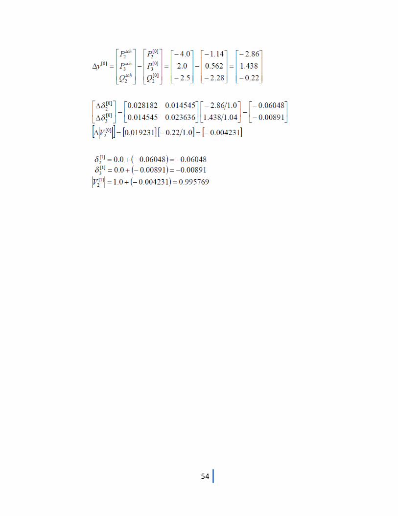
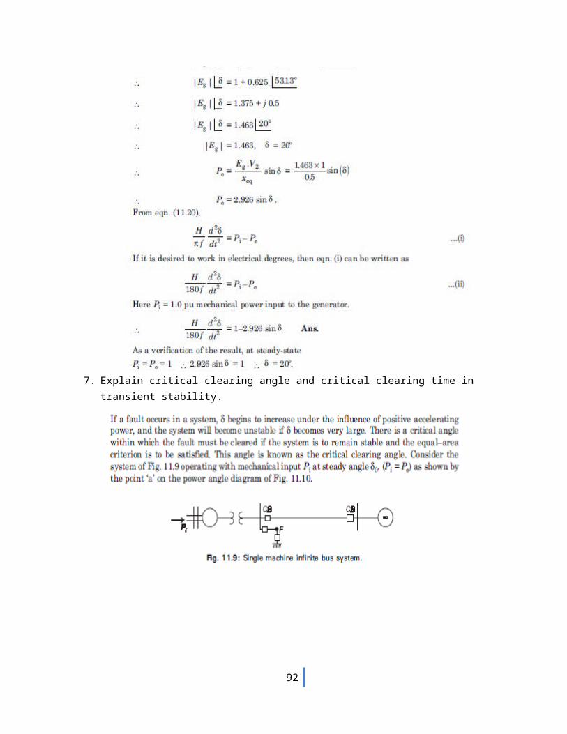
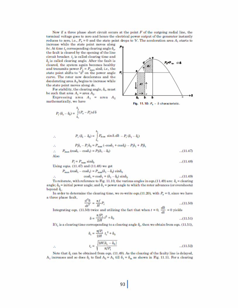
· web viewthe series reactance of the line is 100 ohms. draw the positive, negative and zero...
TRANSCRIPT
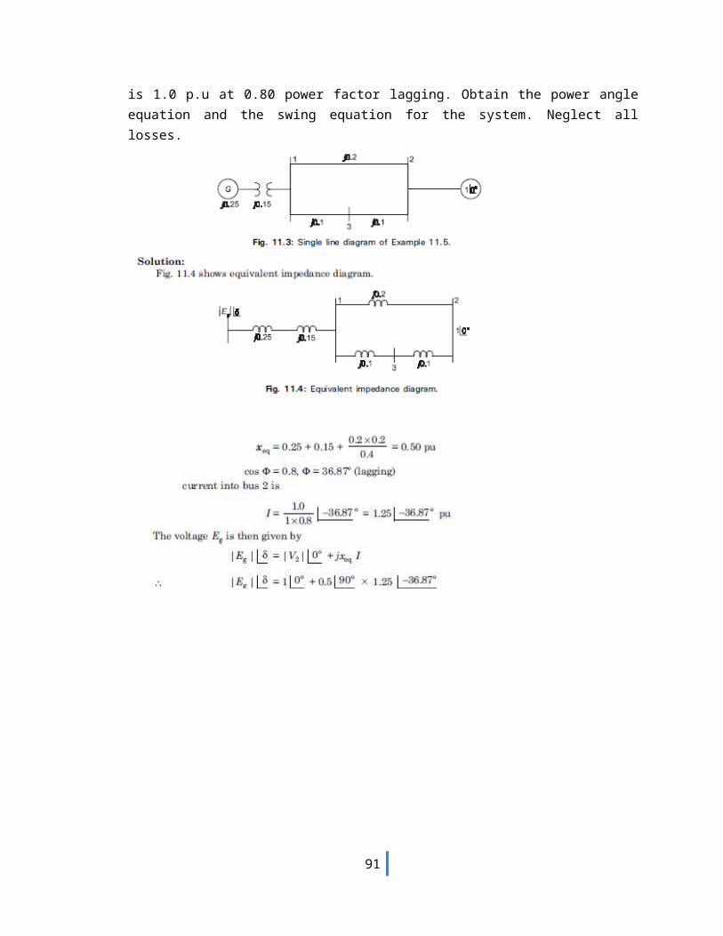
DEPARTMENT OF ELECTRICAL AND ELECTRONICS ENGINEERING
III YEAR/V SEMESTER EE 6501 POWER SYSTEM ANALYSIS
Questions and Answers
UNIT-I THE POWER SYSTEM-AN OVERVIEW
1. What is Power system?A Power system consists of Generation, Transmission and Distribution.
2. What is power system analysis?The evaluation of power system is called as power system analysis
3. What are the functions of power system analysis? To monitor the voltage at various buses, real and reactive power flow
between buses. To design the circuit breakers. To plan future expansion of the existing system To analyze the system under different fault conditions To study the ability of the system for small and large disturbances
(Stability studies)4. What are the components of power system?
The components of power system are Generators, Power transformers, Transmission lines, Distribution lines, Loads and compensating devices like shunt, series, and static VAR compensator.
5. What is modern power system?A modern power system can be subdivided into four major parts: Generation,
Transmission and Sub transmission, Distribution and Loads.6. Define per phase analysis.
A balanced three phase system is always analyses on per phase basis by considering one of the three phase lines and neutral.
7. Draw the per phase model or equivalent circuit model or representation all components of power system?
- Refer Table-1(Modeling of components) -8. What is an infinite bus bar?
A large system whose voltage and frequency remain constant, independent of the power exchange between synchronous machine and bus, and independent of the excitation of the synchronous machine.
9. What is single line diagram?A single line diagram is diagrammatic representation of power system in which
the components are represented by their symbols and interconnection between them are shown by a straight line9eventhough the system is three phase system0.The ratings and the impedances of the components are also marked on the single line diagram.
10. What is the purpose of using single line diagram?The purpose of the single line diagram is to supply in concise form of the
significant information about the system.
1
11. What is impedance diagram? What are the approximations made in impedance diagram?
The impedance diagram is the equivalent circuit of power system in which the various components of power system are represented by their approximate or simplified equivalent circuits. The impedance diagram is used for load flow studies.
Approximation: (i) The neutral reactances are neglected.(ii) The shunt branches in equivalent circuit of transformers are neglected.
12. What is reactance diagram? What are the approximations made in reactance diagram?
The reactance diagram is the simplified equivalent circuit of power system in which the various components of power system are represented by their reactances. The reactance diagram can be obtained from impedance diagram if all the resistive components are neglected. The reactance diagram is used for fault calculations.
Approximation: (i) The neutral reactances are neglected.(ii) The shunt branches in equivalent circuit of transformers are neglected.(iii) The resistances are neglected.(iv) All static loads are neglected.(v) The capacitance of transmission lines are neglected.
13. Define per unit value.The per unit value of any quantity is defined as the ratio of the actual value of the
any quantity to the base value of the same quantity as a decimal.
Per unit value= Actual valueBase value
14. What are the advantages of per unit system?i. Per unit data representation yields valuable relative magnitude information.
ii. Circuit analysis of systems containing transformers of various transformation ratios is greatly simplified.
iii. The p.u systems are ideal for the computerized analysis and simulation of complex power system problems.
iv. Manufacturers usually specify the impedance values of equivalent in per unit of the equipments rating. If the any data is not available, it is easier to assume its per unit value than its numerical value.
v. The ohmic values of impedances are refereed to secondary is different from the value as referee to primary. However, if base values are selected properly, the p.u impedance is the same on the two sides of the transformer.
vi. The circuit laws are valid in p.u systems, and the power and voltages equations are simplified since the factors of √3 and 3 are eliminated.
15. What is the need for base values?The components or various sections of power system may operate at different
voltage and power levels. It will be convenient for analysis of power system if the voltage, power, current and impedance rating of components of power system are expressed with reference to a common value called base value.
2
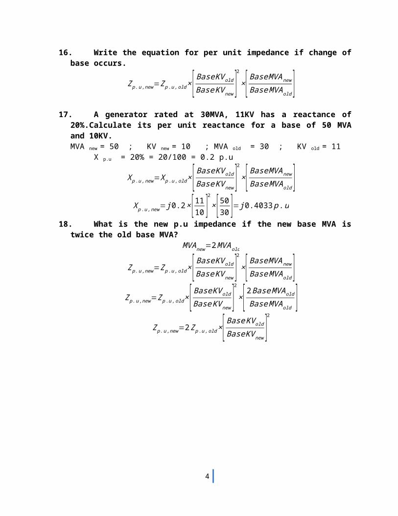
16. Write the equation for per unit impedance if change of base occurs.
Zp . u ,new=Z p .u , old ×[ Base KV old
Base KV new ]2
×[ Base MVAnew
Base MVA old ]17. A generator rated at 30MVA, 11KV has a reactance of 20%.Calculate its per unit
reactance for a base of 50 MVA and 10KV.MVA new = 50 ; KV new = 10 ; MVA old = 30 ; KV old = 11
X p.u = 20% = 20/100 = 0.2 p.u
X p . u ,new=X p .u , old ×[ Base KV old
Base KV new ]2
×[ Base MVAnew
Base MVA old ]X p . u ,new= j 0.2×[ 11
10 ]2
×[5030 ]= j 0.4033 p . u
18. What is the new p.u impedance if the new base MVA is twice the old base MVA?MVA new=2 MVA old
Zp . u ,new=Z p .u , old ×[ Base KV old
Base KV new ]2
×[ Base MVAnew
Base MVA old ]Zp . u ,new=Z p .u , old ×[ Base KV old
Base KV new ]2
×[ 2 Base MVAold
Base MVAold ]Zp . u ,new=2Z p .u ,old ×[ Base KV old
Base KV new ]2
3
EE 601 POWER SYSTEM ANALYSIS
Questions and Answers
UNIT-II POWER FLOW ANALYSIS
19. What is a bus?The meeting point of various components in a power system is called a bus. The
bus is a conductor made of copper or aluminium having negligible resistance .At some of the buses power is being injected into the network, whereas at other buses it is being tapped by the system loads.
20. What is bus admittance matrix?The matrix consisting of the self and mutual admittance of the network of the
power system is called bus admittance matrix (Ybus).21. What are the methods available for forming bus admittance matrix?
Direct inspection method. Singular transformation method.(Primitive network)
22. What is power flow study or load flow study?The study of various methods of solution to power system network is referred to
as load flow study. The solution provides the voltages at various buses, power flowing in various lines and line losses.
23. What are the informations that are obtained from a load flow study?The information obtained from a load flow study is magnitude and phase angle of
voltages, real and reactive power flowing in each line and the line losses. The load flow solution also gives the initial conditions of the system when the transient behavior of the system is to be studied.
24. What is the need for load flow study?The load flow study of a power system is essential to decide the best operation of
existing system and for planning the future expansion of the system. It is also essential foe designing a new power system.
25. What are the quantities associated with each bus in a system?Each bus in a power system is associated with four quantities and they
are real power (P), reactive power (Q), magnitude of voltage (V), and phase angle of voltage (δ).
26. What are the different types of buses in a power system? Or how the buses are classified and what are its types?
Types of bus Known or specified quantities
Unknown quantities or quantities to be
determined.Slack or Swing or Reference bus
V, δ P,Q
Generator or Voltage P, V Q, δ
4
control or PV busLoad or PQ bus P, Q V, δ
27. What is the need for slack bus?The slack bus is needed to account for transmission line losses.
In a power system the total power generated will be equal to sum of power consumed by loads and losses. In a power system only the generated power and load power are specified for buses. The slack bus is assumed to generate the power required for losses. Since the losses are unknown the real and reactive power are not specified for slack bus.
28. Why do we go for iterative methods to solve load flow problems?
The load flow equations are non linear algebraic equations and so explicit solution as not possible. The solution of non linear equations can be obtained only by iterative numerical techniques.
29. What are the methods mainly used for solution of load flow study?
The Gauss seidal method, Newton Raphson method and Fast decouple methods.
30. What do you mean by a flat voltage start?In iterative method of load flow solution, the initial voltages of all
buses except slack bus assumed as 1+j0 p.u. This is refereed to as flat voltage start
31. Discuss the effect of acceleration factor in load flow study.
Acceleration factor is used in gauss seidal method of load flow solution to increase the rate of convergence. Best value of A.F=1.632. When the generator buses are treated as load bus.
If the reactive power constraints of a generator bus violates the specified limits then the generator is treated as load bus.
33. What are the advantages and disadvantages of Gauss seidal method?
Advantages: Calculations are simple and so the programming task is lessees. The memory requirement is less. Useful for small systems; Disadvantages: Requires large no. of iterations to reach converge .Not suitable for large systems. Convergence time increases with size of the system
34. What are the advantages and disadvantages of N.R method?
Advantages: Faster, more reliable and results are accurate, require less number of iterations; Disadvantages: Program is more complex, memory is more complex.
5
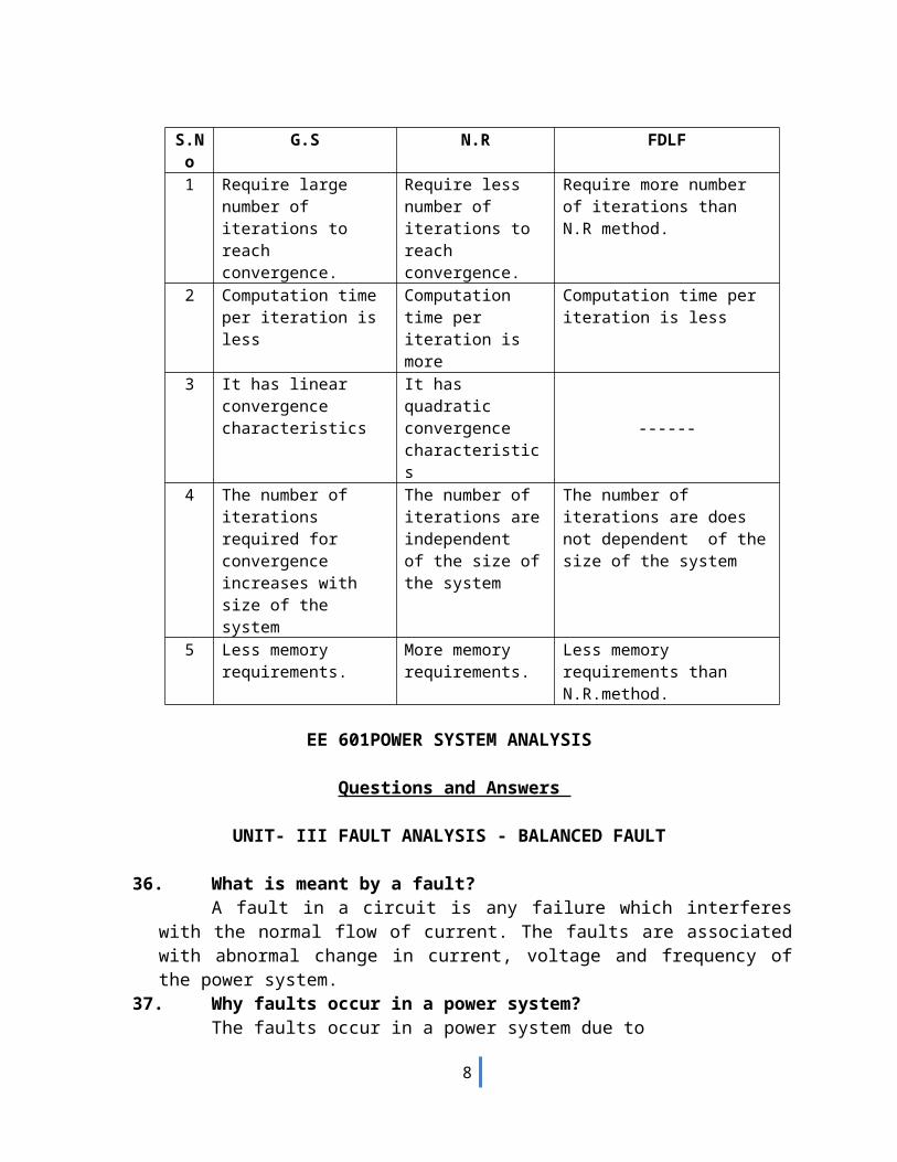
35. Compare the Gauss seidel and Newton raphson methods of load flow study.
S.No
G.S N.R FDLF
1 Require large number of iterations to reach convergence.
Require less number of iterations to reach convergence.
Require more number of iterations than N.R method.
2 Computation time per iteration is less
Computation time per iteration is more
Computation time per iteration is less
3 It has linear convergence characteristics
It has quadratic convergence characteristics
------
4 The number of iterations required for convergence increases with size of the system
The number of iterations are independent of the size of the system
The number of iterations are does not dependent of the size of the system
5 Less memory requirements.
More memory requirements.
Less memory requirements than N.R.method.
EE 601POWER SYSTEM ANALYSIS
Questions and Answers
UNIT- III FAULT ANALYSIS - BALANCED FAULT
36. What is meant by a fault?A fault in a circuit is any failure which interferes with the normal flow of current.
The faults are associated with abnormal change in current, voltage and frequency of the power system.
37. Why faults occur in a power system?The faults occur in a power system due to
Insulation failure of equipment Flashover of lines initiated by a lighting stroke Due to permanent damage to conductors and towers or due to accidental
faulty operations.38. List the various types of faults.
(i) Series fault or open circuit fault One open conductor fault Two open conductor fault
(ii) Shunt fault or short circuit fault. Symmetrical fault or balanced fault
Three phase fault
6
Unsymmetrical fault or unbalanced fault Line to ground (L-G) fault Line to Line (L-L) fault Double line to ground (L-L-G) fault
39. Write the relative frequency of occurrence of various types of faults.Types of fault Relative frequency of
occurrence of faultsThree phase fault 5%Double line to ground fault 10%Line to Line fault 15%Line to ground fault 70%
.40. State and explain symmetrical fault or balanced three phase fault.
This type of fault is defined as the simultaneous short circuit across all the three phases. It occurs infrequently, but it is the most severe type of fault encountered. Because the network is balanced, it is solved by per phase basis using Thevenins theorem or bus impedance matrix or KVL, KCL laws.
41. What is the need for short circuit studies or fault analysis?Short circuit studies are essential in order to design or develop the protective
schemes for various parts of the system .To estimate the magnitude of fault current for the proper choice of circuit breaker and protective relays.
42. What is bolted fault or solid fault?A Fault represents a structural network change equivalent with that
caused by the addition of impedance at the place of a fault. If the fault impedance is zero, the fault is referred as bolted fault or solid fault.
43. What is the reason for transients during short circuits?The faults or short circuits are associated with sudden change in
currents. Most of the components of the power system have inductive property which opposes any sudden change in currents, so the faults are associated with transients.
44. What is meant by doubling effect?If a symmetrical fault occurs when the voltage wave is going
through zero then the maximum momentary short circuit current will be double the value of maximum symmetrical short circuit current. This effect is called doubling effect.
45. Define DC off set current.The unidirectional transient component of short circuit current is
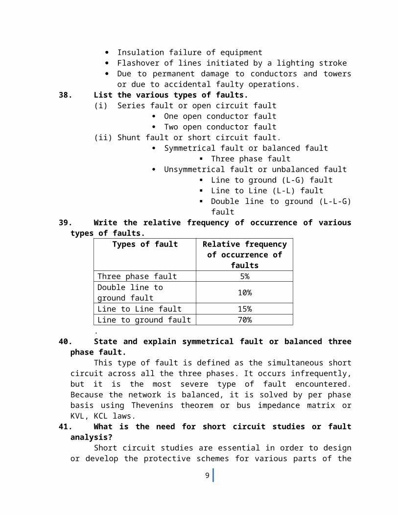
called DC off set current.46. What is synchronous reactance or steady state condition
reactance?The synchronous reactance is the ratio of induced emf and the
steady state rms current. It is the sum of leakage reactance (Xl) and the armature reactance (Xa).
X d=Xa+X l
7
Fault
Fault
Fault
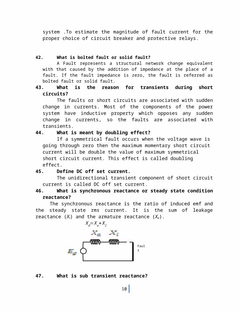
47. What is sub transient reactance?The synchronous reactance is the ratio of induced emf on no load
and the sub transient symmetrical rms current.
X d' '=X l+
11Xa
+ 1X f
+ 1Xdw
48. What is transient reactance?The synchronous reactance is the ratio of induced emf on no load
and the transient symmetrical rms current.
X d' =X l+
11Xa
+ 1X f
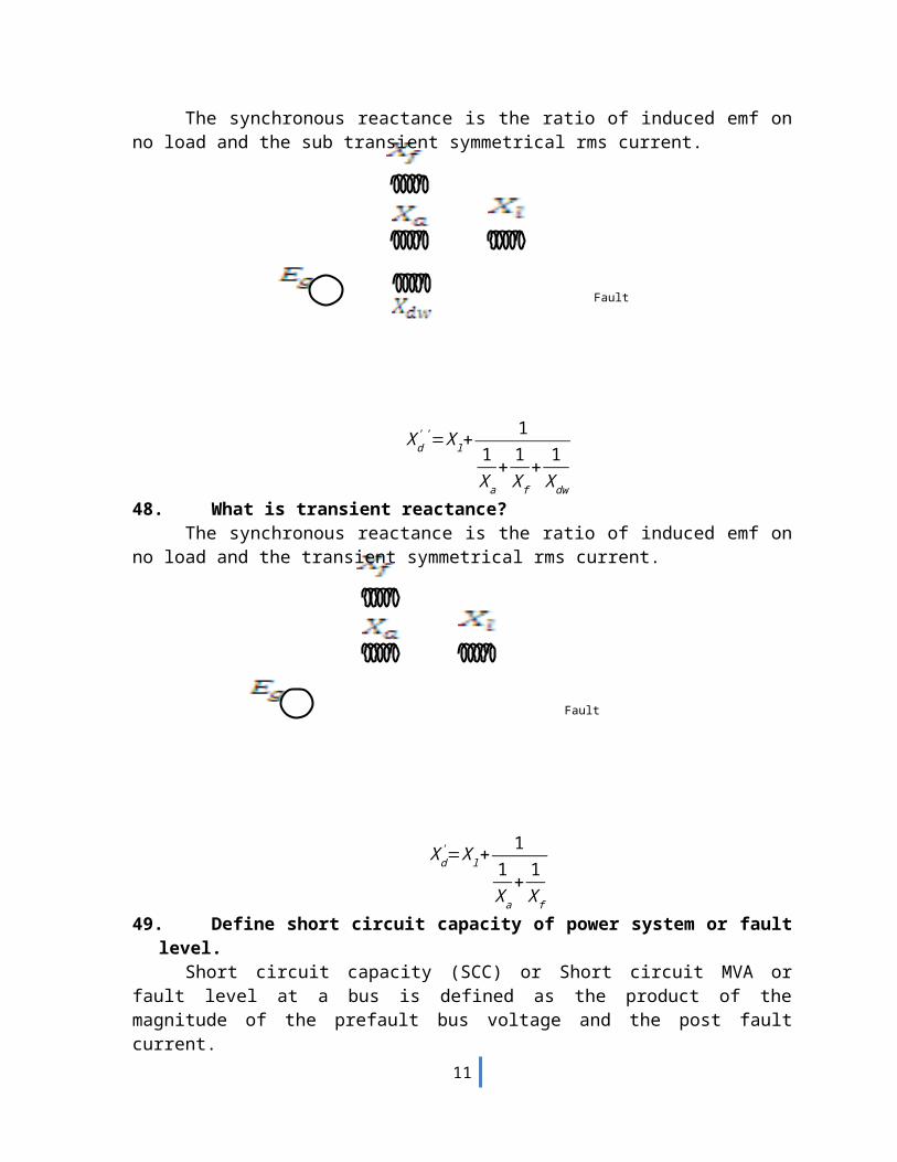
49. Define short circuit capacity of power system or fault level.
8
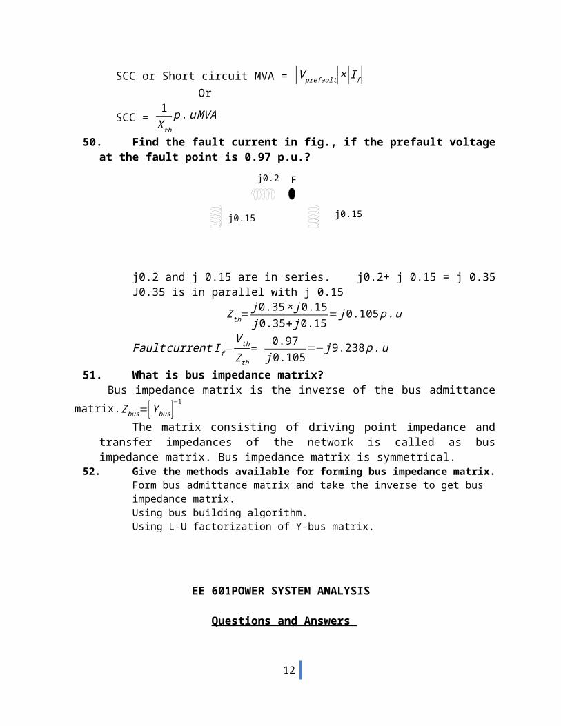
j0.15j0.15
j0.2 F
Short circuit capacity (SCC) or Short circuit MVA or fault level at a bus is defined as the product of the magnitude of the prefault bus voltage and the post fault current.
SCC or Short circuit MVA = |V prefault|×|I f|Or
SCC = 1X th
p .u MVA
50. Find the fault current in fig., if the prefault voltage at the fault point is 0.97 p.u.?
j0.2 and j 0.15 are in series. j0.2+ j 0.15 = j 0.35J0.35 is in parallel with j 0.15
Zth=j 0.35 × j0.15j 0.35+ j 0.15
= j 0.105 p .u
Fault current I f=V th
Z th= 0.97
j 0.105=− j 9.238 p .u
51. What is bus impedance matrix?Bus impedance matrix is the inverse of the bus admittance matrix.
Zbus= [Y bus]−1
The matrix consisting of driving point impedance and transfer impedances of the network is called as bus impedance matrix. Bus impedance matrix is symmetrical.
52. Give the methods available for forming bus impedance matrix.Form bus admittance matrix and take the inverse to get bus impedance matrix.Using bus building algorithm.Using L-U factorization of Y-bus matrix.
EE 601POWER SYSTEM ANALYSIS
Questions and Answers
UNIT- IV FAULT ANALYSIS – SYMMETRICAL COMPONENTS AND UNBALANCED FAULT
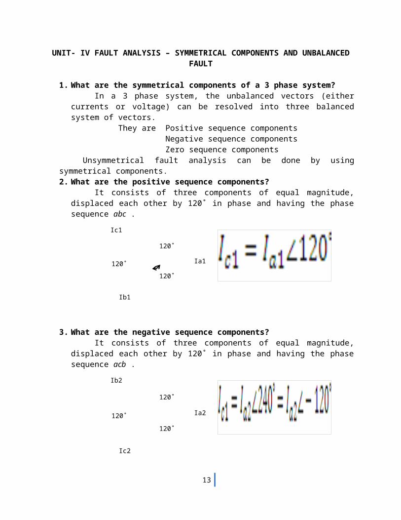
1. What are the symmetrical components of a 3 phase system?
9
120˚
120˚
120˚ Ia1
Ib1
Ic1
120˚
120˚
120˚ Ia2
Ic2
Ib2
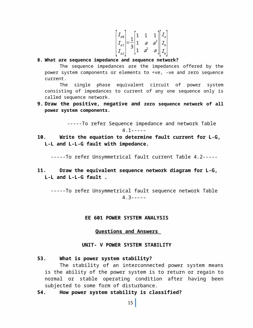
Ia0
Ib0Ic0 Ia0 = Ib0 = Ic0
In a 3 phase system, the unbalanced vectors (either currents or voltage) can be resolved into three balanced system of vectors.
They are Positive sequence componentsNegative sequence components Zero sequence components
Unsymmetrical fault analysis can be done by using symmetrical components. 2. What are the positive sequence components?
It consists of three components of equal magnitude, displaced each other by 120˚ in phase and having the phase sequence abc .
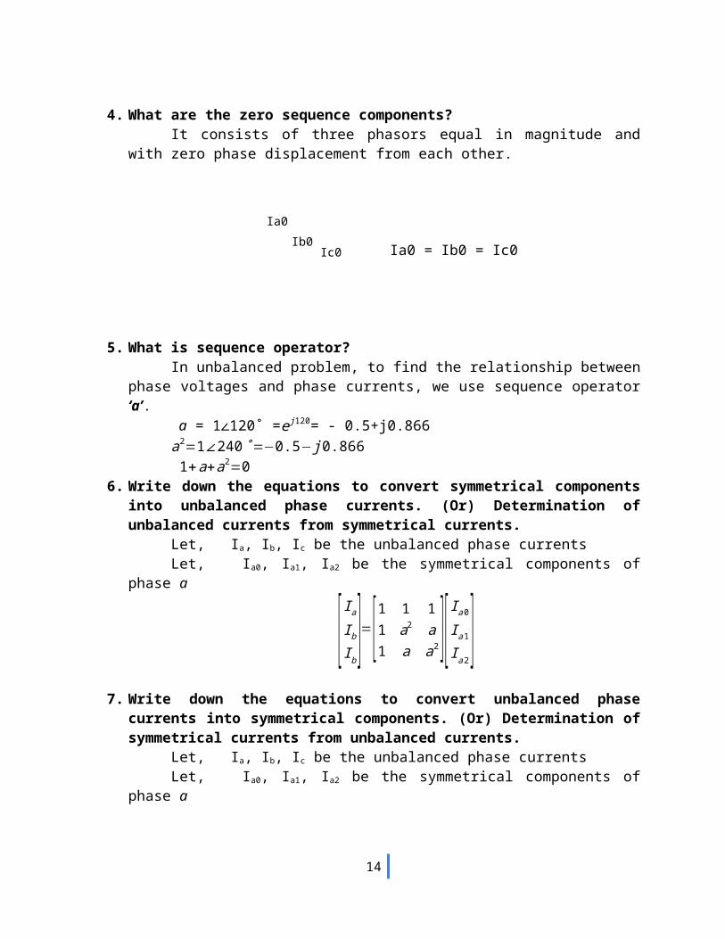
3. What are the negative sequence components?It consists of three components of equal magnitude, displaced each other by 120˚
in phase and having the phase sequence acb .
4. What are the zero sequence components?It consists of three phasors equal in magnitude and with zero phase displacement
from each other.
5. What is sequence operator?
10
In unbalanced problem, to find the relationship between phase voltages and phase currents, we use sequence operator ‘a’.
a = 1∠120˚ =e j 120= - 0.5+j0.866a2=1∠240 ˚=−0.5− j 0.866 1+a+a2=0
6. Write down the equations to convert symmetrical components into unbalanced phase currents. (Or) Determination of unbalanced currents from symmetrical currents.
Let, Ia, Ib, Ic be the unbalanced phase currentsLet, Ia0, Ia1, Ia2 be the symmetrical components of phase a
[ Ia
Ib
Ib]=[1 1 1
1 a2 a1 a a2][ I a 0
I a 1
I a 2]
7. Write down the equations to convert unbalanced phase currents into symmetrical components. (Or) Determination of symmetrical currents from unbalanced currents.
Let, Ia, Ib, Ic be the unbalanced phase currentsLet, Ia0, Ia1, Ia2 be the symmetrical components of phase a
[ Ia0
I a1
I a2]=1
3 [1 1 11 a a2
1 a2 a ][ I a
Ib
Ib]
8. What are sequence impedance and sequence network?The sequence impedances are the impedances offered by the power
system components or elements to +ve, -ve and zero sequence current.The single phase equivalent circuit of power system consisting of
impedances to current of any one sequence only is called sequence network.9. Draw the positive, negative and zero sequence network of all
power system components.
-----To refer Sequence impedance and network Table 4.1-----10. Write the equation to determine fault current for L-G, L-L
and L-L-G fault with impedance.
-----To refer Unsymmetrical fault current Table 4.2-----
11. Draw the equivalent sequence network diagram for L-G, L-L and L-L-G fault .
-----To refer Unsymmetrical fault sequence network Table 4.3-----
EE 601 POWER SYSTEM ANALYSIS
Questions and Answers
11
UNIT- V POWER SYSTEM STABILITY
53. What is power system stability?The stability of an interconnected power system means is the ability of the power
system is to return or regain to normal or stable operating condition after having been subjected to some form of disturbance.
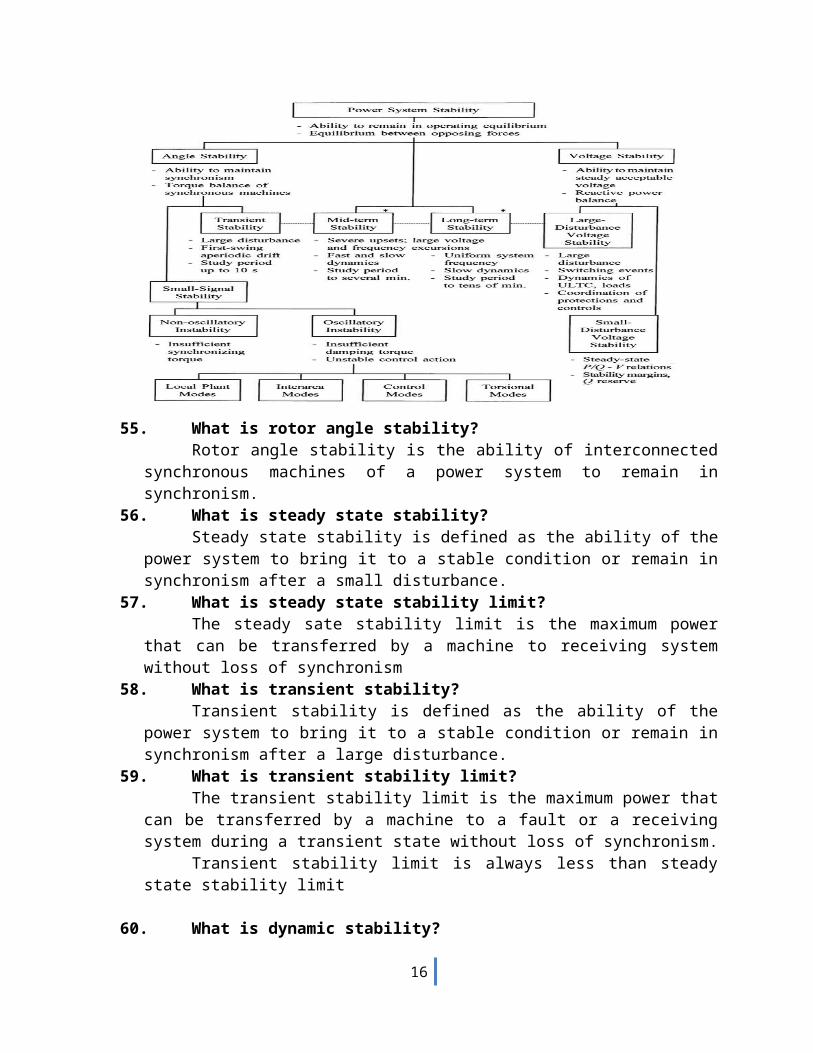
54. How power system stability is classified?
55. What is rotor angle stability?Rotor angle stability is the ability of interconnected synchronous machines of a
power system to remain in synchronism.56. What is steady state stability?
Steady state stability is defined as the ability of the power system to bring it to a stable condition or remain in synchronism after a small disturbance.
57. What is steady state stability limit?The steady sate stability limit is the maximum power that can be transferred by a
machine to receiving system without loss of synchronism58. What is transient stability?
Transient stability is defined as the ability of the power system to bring it to a stable condition or remain in synchronism after a large disturbance.
59. What is transient stability limit?The transient stability limit is the maximum power that can be transferred by a
machine to a fault or a receiving system during a transient state without loss of synchronism.
Transient stability limit is always less than steady state stability limit
60. What is dynamic stability?
12
It is the ability of a power system to remain in synchronism after the initial swing (transient stability period) until the system has settled down to the new steady state equilibrium condition
61. What is voltage stability?It is the ability of a power system to maintain steady acceptable voltages at all
buses in the system under normal operating conditions and after being subjected to a disturbance.
62. State the causes of voltage instability.A system enters a state of voltage instability when a disturbance, increase in load
demand, or change in system condition causes a progressive and uncontrollable drop in voltage
The main factor causing instability is the inability of the power system to meet the demand for reactive power.
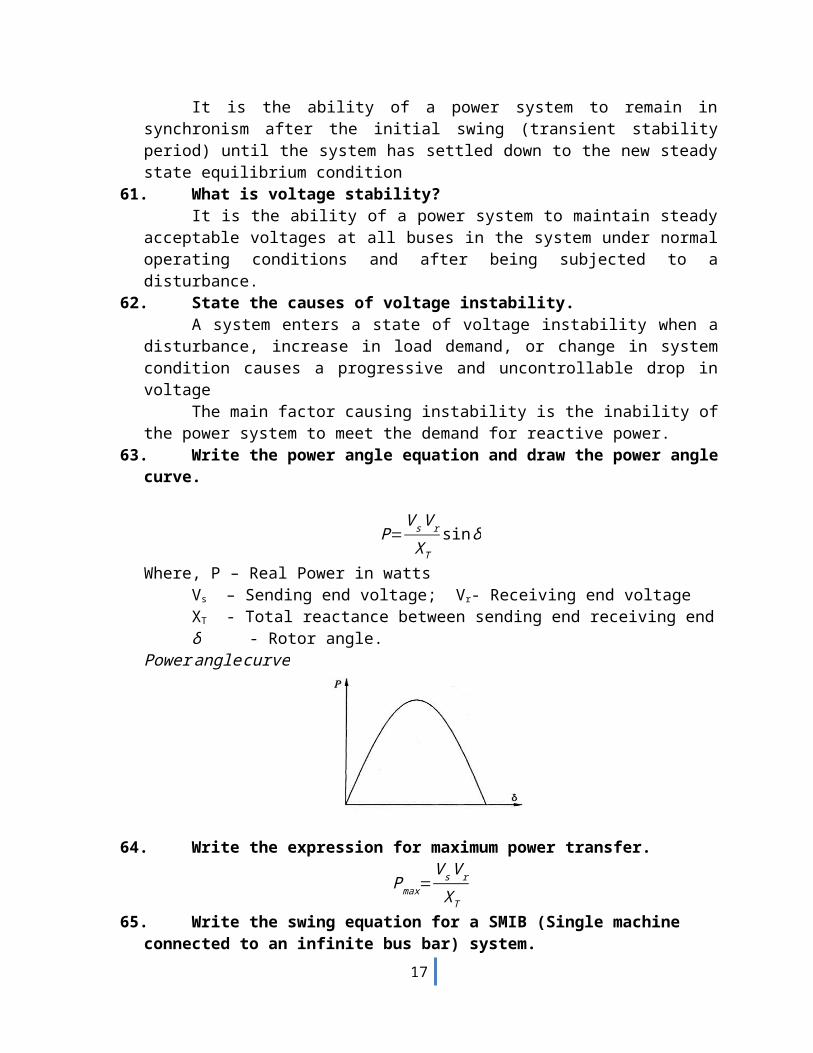
63. Write the power angle equation and draw the power angle curve.
P=V s V r
XTsin δ
Where, P – Real Power in wattsVs – Sending end voltage; Vr- Receiving end voltageXT - Total reactance between sending end receiving end δ - Rotor angle.
Power angle curve
64. Write the expression for maximum power transfer.
Pmax=V sV r
XT
65. Write the swing equation for a SMIB (Single machine connected to an infinite bus bar) system.
Hπ f
d2δd t 2 =Pm−P e
Since M ∈p . u=H /π f
Md2δd t 2 =Pm−P e
Where H = inertia constant in MW/MVAf = frequency in Hz
M = inertia constant in p.u
13
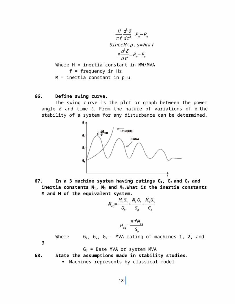
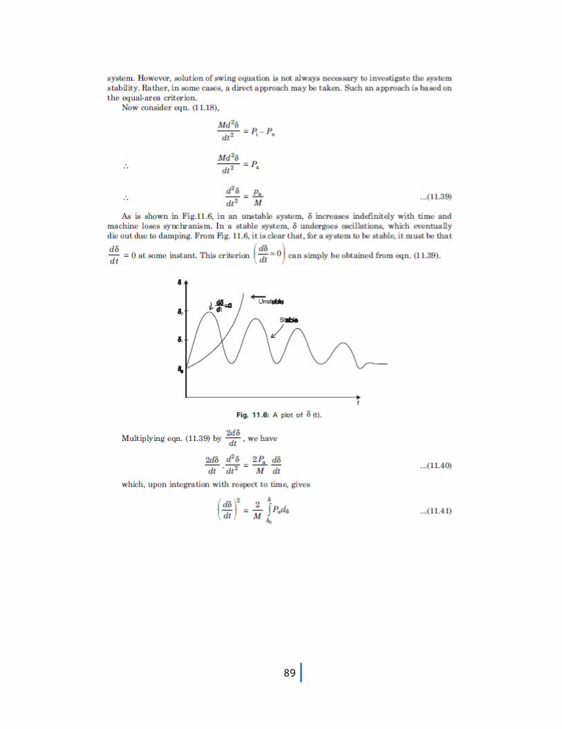
66. Define swing curve.The swing curve is the plot or graph between the power angle δ and time t. From
the nature of variations of δ the stability of a system for any disturbance can be determined.
67. In a 3 machine system having ratings G1, G2 and G3 and inertia constants M1, M2 and M3.What is the inertia constants M and H of the equivalent system.
M eq=M 1G1
Gb+
M 2 G2
G b+
M 3G3
Gb
H eq=π f M eq
Gb
Where G1, G2, G3 – MVA rating of machines 1, 2, and 3Gb = Base MVA or system MVA
68. State the assumptions made in stability studies. Machines represents by classical model The losses in the system are neglected (all resistance are neglected) The voltage behind transient reactance is assumed to remain constant. Controllers are not considered ( Shunt and series capacitor ) Effect of damper winding is neglected.
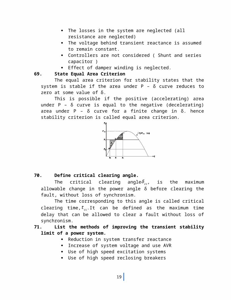
69. State Equal Area CriterionThe equal area criterion for stability states that the system is stable if the area
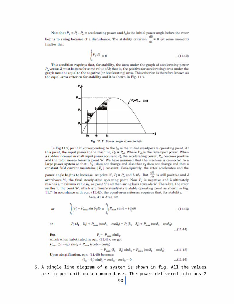
under P – δ curve reduces to zero at some value of δ.This is possible if the positive (accelerating) area under P – δ curve is equal to the
negative (decelerating) area under P – δ curve for a finite change in δ. hence stability criterion is called equal area criterion.
14
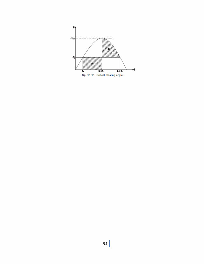
70. Define critical clearing angle.The critical clearing angleδ cc, is the maximum allowable change in the power
angle δ before clearing the fault, without loss of synchronism.The time corresponding to this angle is called critical clearing time,t cc.It can be
defined as the maximum time delay that can be allowed to clear a fault without loss of synchronism.
71. List the methods of improving the transient stability limit of a power system. Reduction in system transfer reactance Increase of system voltage and use AVR Use of high speed excitation systems Use of high speed reclosing breakers
72. What are the numerical integration methods of power system stability?i. Point by point method or step by step method
ii. Euler methodiii. Modified Euler methodiv. Runge-Kutta method(R-K method)
15
j 50ΩG1 M
T1 T2
16 MARKS
UNIT-I
THE POWER SYSTEM-AN OVERVIEW AND MODELLING
1. Explain the modeling of generator, load, transmission line and transformer for power flow, short circuit and stability studies.
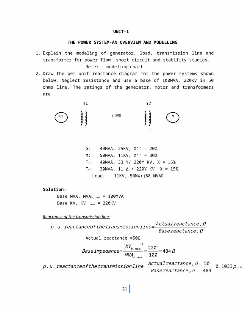
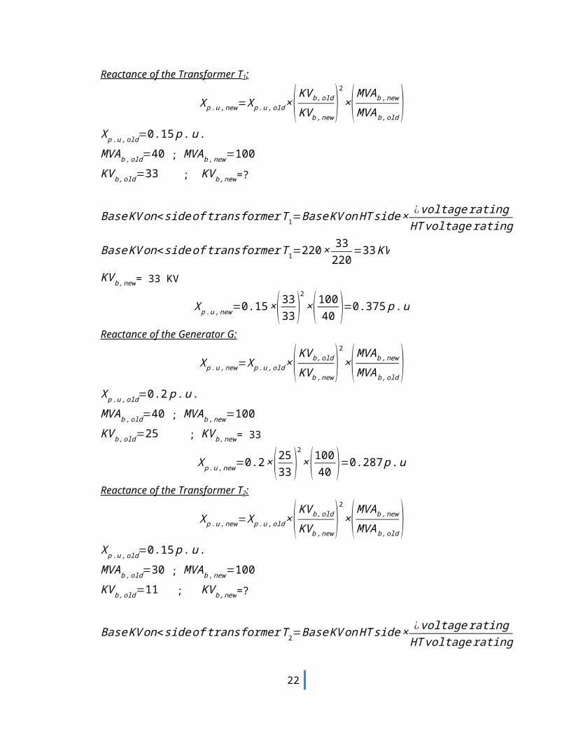
Refer - modeling chart2. Draw the per unit reactance diagram for the power systems shown below. Neglect resistance
and use a base of 100MVA, 220KV in 50 ohms line. The ratings of the generator, motor and transformers are
G: 40MVA, 25KV, X’’ = 20%M: 50MVA, 11KV, X’’ = 30%T1: 40MVA, 33 Y/ 220Y KV, X = 15%T2: 30MVA, 11 Δ / 220Y KV, X = 15%
Load: 11KV, 50MW+j68 MVAR
Solution:Base MVA, MVAb, new = 100MVABase KV, KVb, new = 220KV
Reactance of the transmission line:
p .u . reactance of thetransmissionline= Actual reactance , ΩBase reactance ,Ω
Actual reactance =50Ω
Base impedance=( KV b , new )2
MVA b ,new=
2202
100 =484 Ω
p.u . reactance of thetransmissionline= Actual reactance , ΩBase reactance ,Ω
= 50484
=0.1033 p .u
16
Reactance of the Transformer T1:
X p . u ,new=X p .u , old ×( KV b , old
KV b ,new)
2
×( MVA b ,new
MVAb , old)
X p . u ,old=0.15 p . u . MVA b ,old=40 ; MVA b ,new=100KV b ,old=33 ; KV b ,new=?
Base KV on<side of transformer T1=Base KV on HT side × ¿voltage ratingHT voltage rating
Base KV on<side of transformer T1=220× 33220
=33 KV
KV b ,new= 33 KV
X p . u ,new=0.15×( 3333 )
2
×(10040 )=0.375 p .u
Reactance of the Generator G:
X p . u ,new=X p .u , old ×( KV b , old
KV b ,new)
2
×( MVAb ,new
MVAb , old)
X p . u ,old=0.2 p . u . MVA b ,old=40 ; MVAb ,new=100KV b ,old=25 ; KV b ,new= 33
X p . u ,new=0.2×(2533 )
2
×( 10040 )=0.287 p .u
Reactance of the Transformer T2:
X p . u ,new=X p .u , old ×( KV b , old
KV b ,new)
2
×( MVAb ,new
MVAb , old)
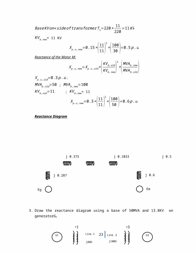
X p . u ,old=0.15 p . u . MVA b ,old=30 ; MVAb ,new=100KV b ,old=11 ; KV b ,new=?
Base KV on<side of transformer T2=Base KV on HT side × ¿voltageratingHT voltage rating
Base KV on<side of transformer T1=220× 11220
=11 KV
KV b ,new= 11 KV
X p . u ,new=0.15×( 1111)
2
×(10030 )=0.5 p .u
Reactance of the Motor M:
X p . u ,new=X p .u , old ×( KV b , old
KV b ,new)
2
×( MVA b ,new
MVAb , old)
17
j 0.287
j 0.375 j 0.1033 j 0.5
j 0.6
Eg Em
G1 G3
G2
T1 T3
T2
Line 1 Line 2
j80Ω j100Ω
X p . u ,old=0.3 p . u . MVA b ,old=50 ; MVAb ,new=100KV b ,old=11 ; KV b ,new= 11
X p . u ,new=0.3×(1111)
2
×( 10050 )=0.6 p .u
Reactance Diagram
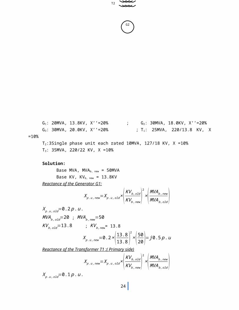
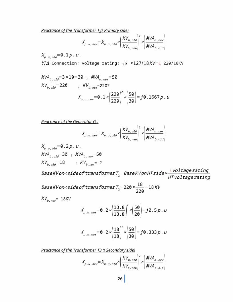
3. Draw the reactance diagram using a base of 50MVA and 13.8KV on generatorG1
G1: 20MVA, 13.8KV, X’’=20% ; G2: 30MVA, 18.0KV, X’’=20%
18
G3: 30MVA, 20.0KV, X’’=20% ; T1: 25MVA, 220/13.8 KV, X =10%T2:3Single phase unit each rated 10MVA, 127/18 KV, X =10%T3: 35MVA, 220/22 KV, X =10%
Solution:Base MVA, MVAb, new = 50MVABase KV, KVb, new = 13.8KV
Reactance of the Generator G1:
X p . u ,new=X p .u , old ×( KV b , old
KV b ,new)
2
×( MVA b ,new
MVAb , old)
X p . u ,old=0.2 p . u . MVAb ,old=20 ; MVA b ,new=50KV b ,old=13.8 ; KV b ,new= 13.8
X p . u ,new=0.2×( 13.813.8 )
2
×( 5020 )= j 0.5 p .u
Reactance of the Transformer T1 :( Primary side)
X p . u ,new=X p .u , old ×( KV b , old
KV b ,new)
2
×( MVA b ,new
MVAb , old)
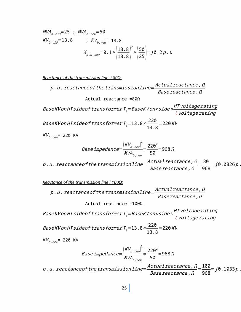
X p . u ,old=0.1 p . u . MVAb ,old=25 ; MVA b ,new=50KV b ,old=13.8 ; KV b ,new= 13.8
X p . u ,new=0.1×( 13.813.8 )
2
×( 5025 )= j 0.2 p . u
Reactance of the transmission line j 80Ω:
p .u . reactance of thetransmissionline= Actual reactance , ΩBase reactance ,Ω
Actual reactance =80Ω
Base KV on HT side of transformer T 1=Base KV on<side × HT voltage rating¿voltage rating
Base KV on HT side of transformer T 1=13.8× 22013.8
=220 KV
KV b ,new= 220 KV
Base impedance=( KV b , new )2
MVA b ,new=
2202
50 =968 Ω
p .u . reactance of thetransmissionline= Actual reactance , ΩBase reactance ,Ω
= 80968
= j 0.0826 p .u
19

Reactance of the transmission line j 100Ω:
p .u . reactance of thetransmissionline= Actual reactance , ΩBase reactance ,Ω
Actual reactance =100Ω
Base KV on HT side of transformer T 1=Base KV on<side × HT voltage rating¿voltage rating
Base KV on HT side of transformer T 1=13.8× 22013.8
=220 KV
KV b ,new= 220 KV
Base impedance=( KV b , new )2
MVA b ,new=
2202
50 =968 Ω
p .u . reactance of thetransmissionline= Actual reactance , ΩBase reactance ,Ω
=100968
= j 0.1033 p .u
Reactance of the Transformer T2:( Primary side)
X p . u ,new=X p .u , old ×( KV b , old
KV b ,new)
2
×( MVAb ,new
MVAb , old)
X p . u ,old=0.1 p . u . Y / Δ Connection; voltage rating: √3 ×127 /18 KV =¿ 220/18KV
MVA b ,old=3×10=30 ; MVA b,new=50KV b ,old=220 ; KV b ,new=220?
X p . u ,new=0.1×( 220220 )
2
×( 5030 )= j0.1667 p .u
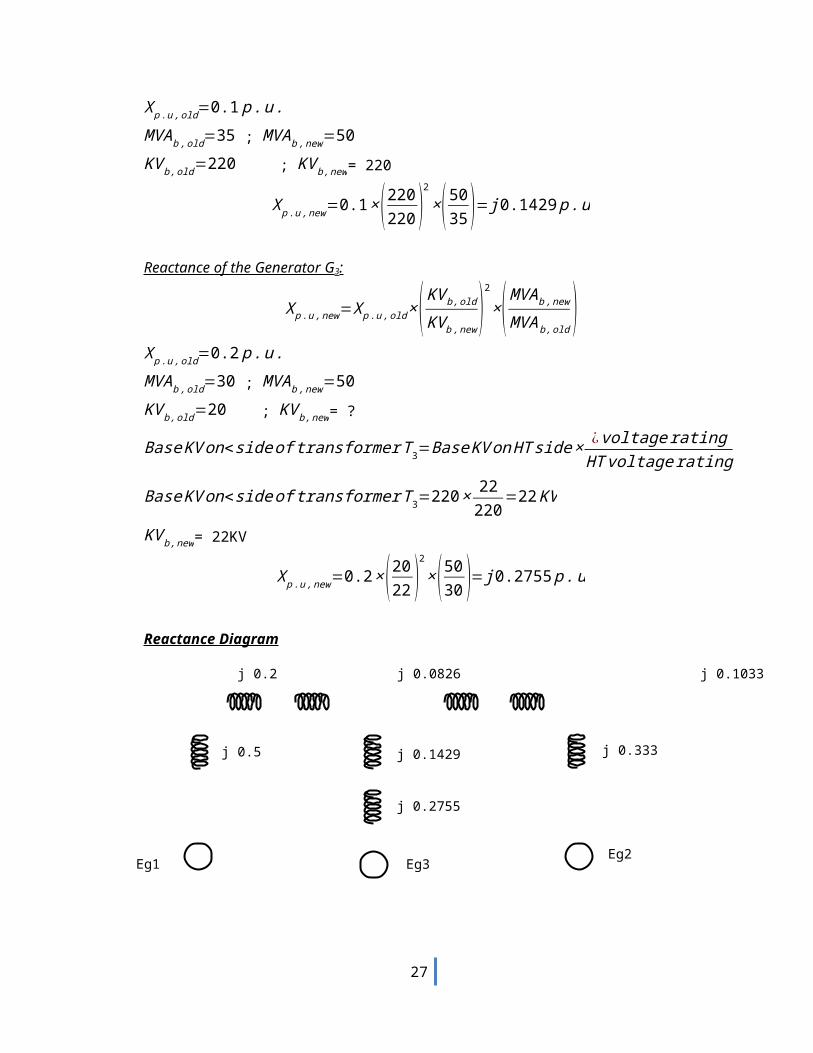
Reactance of the Generator G2:
X p . u ,new=X p .u , old ×( KV b , old
KV b ,new)
2
×( MVA b ,new
MVAb , old)
X p . u ,old=0.2 p . u . MVA b ,old=30 ; MVA b ,new=50KV b ,old=18 ; KV b ,new= ?
Base KV on<side of transformer T2=Base KV on HT side × ¿voltageratingHT voltage rating
Base KV on<side of transformer T2=220× 18220
=18 KV
KV b ,new= 18KV
X p . u ,new=0.2×( 13.813.8 )
2
×( 5020 )= j 0.5 p .u
20
j 0.5
j 0.2 j 0.0826 j 0.1033 j 0.1667
j 0.333
Eg1Eg2
Eg3
j 0.1429
j 0.2755
X p . u ,new=0.2×( 1818 )
2
×( 5030 )= j 0.333 p .u
Reactance of the Transformer T3 :( Secondary side)
X p . u ,new=X p .u , old ×( KV b , old
KV b ,new)
2
×( MVA b ,new
MVAb , old)
X p . u ,old=0.1 p . u . MVA b ,old=35 ; MVA b ,new=50KV b ,old=220 ; KV b ,new= 220
X p . u ,new=0.1×(220220 )
2
×( 5035 )= j0.1429 p .u
Reactance of the Generator G3:
X p . u ,new=X p .u , old ×( KV b , old
KV b ,new)
2
×( MVAb ,new
MVAb , old)
X p . u ,old=0.2 p . u . MVA b ,old=30 ; MVAb ,new=50KV b ,old=20 ; KV b ,new= ?
Base KV on<side of transformer T3=Base KV on HT side × ¿voltageratingHT voltage rating
Base KV on<side of transformer T3=220× 22220
=22 KV
KV b ,new= 22KV
X p . u ,new=0.2×(2022 )
2
×( 5030 )= j0.2755 p .u
Reactance Diagram
21
Z=40 + j 150Ω
G1T1 T2
G2
Load
1000VA250V
Z = j0.2 p.u
2000VA250V
Z = j0.3 p.u
4000VA250/800VZ = j0.2 p.u
8000VA1000/500VZ = j0.06 p.u
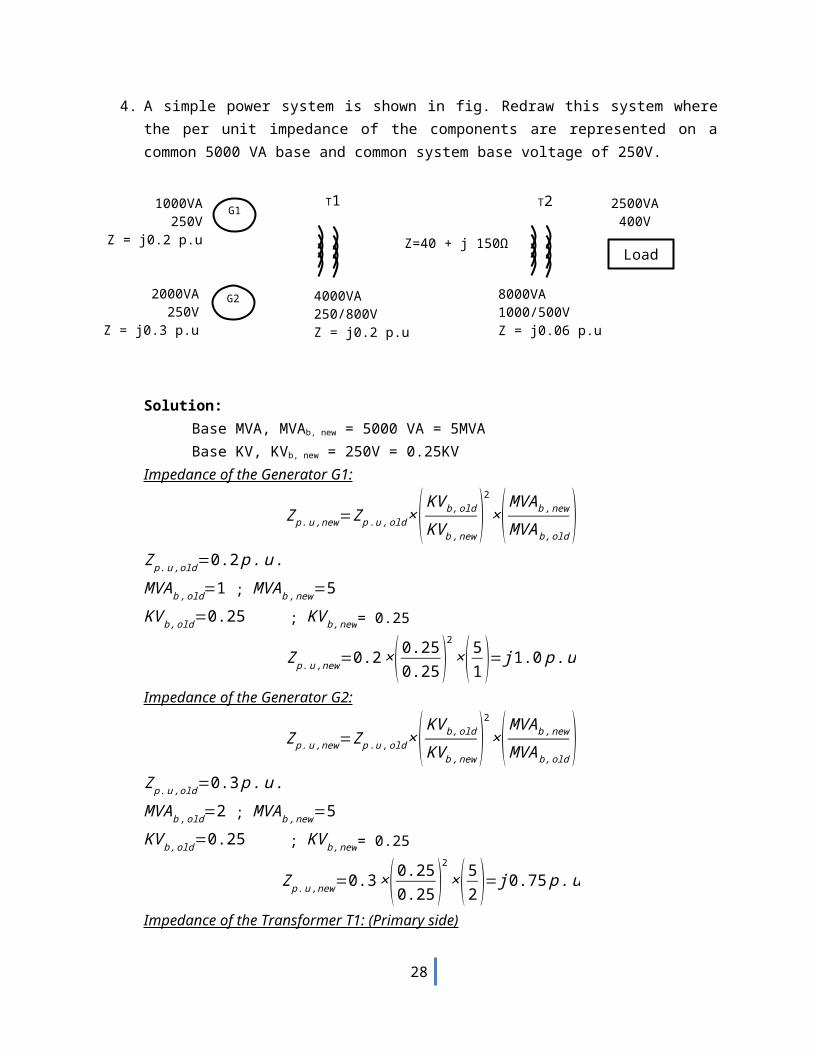
2500VA400V
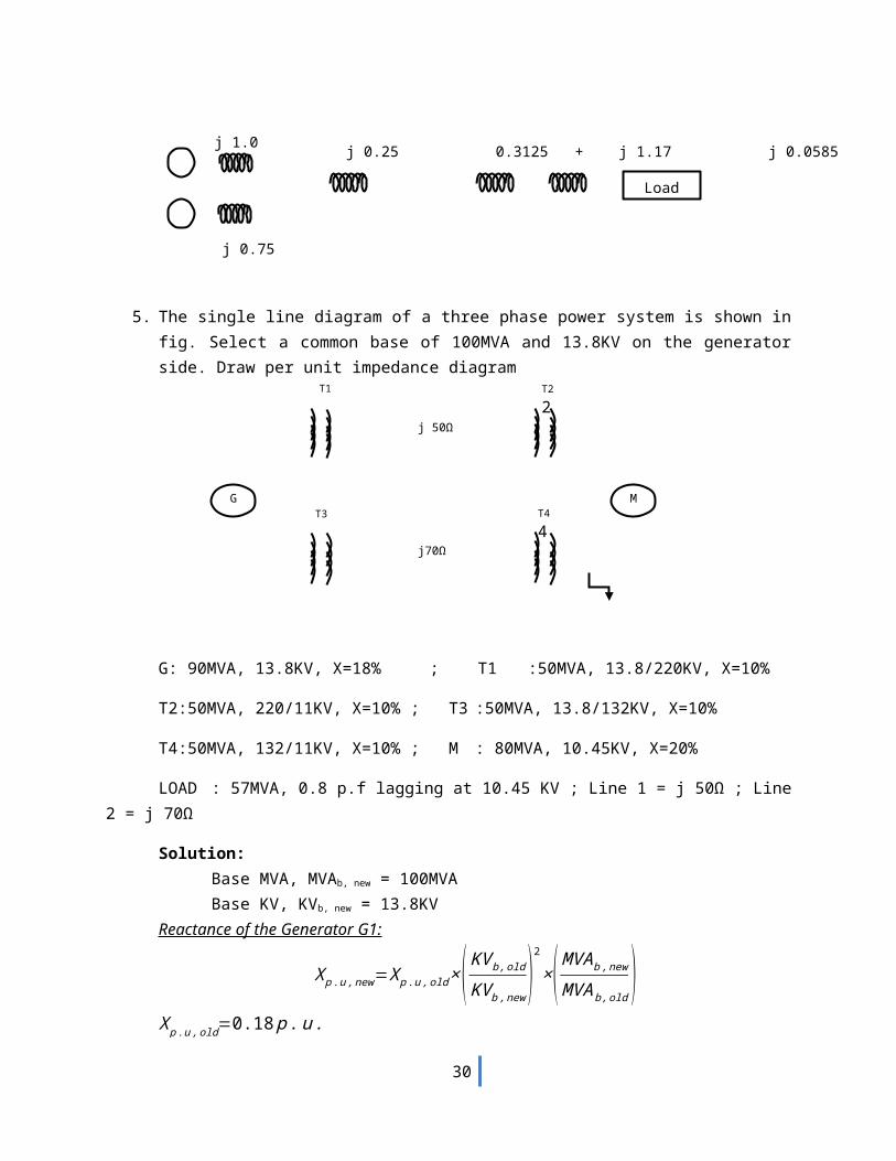
4. A simple power system is shown in fig. Redraw this system where the per unit impedance of the components are represented on a common 5000 VA base and common system base voltage of 250V.
Solution:Base MVA, MVAb, new = 5000 VA = 5MVABase KV, KVb, new = 250V = 0.25KV
Impedance of the Generator G1:
Zp . u ,new=Z p .u , old ×( KV b , old
KV b ,new)
2
×( MVAb ,new
MVAb , old)
Zp . u ,old=0.2 p . u . MVA b ,old=1 ; MVA b ,new=5KV b ,old=0.25 ; KV b ,new= 0.25
Zp . u ,new=0.2×(0.250.25 )
2
×(51 )= j1.0 p .u
Impedance of the Generator G2:
Zp . u ,new=Z p .u , old ×( KV b , old
KV b ,new)
2
×( MVAb ,new
MVAb , old)
Zp . u ,old=0.3 p . u . MVA b ,old=2 ; MVA b ,new=5KV b ,old=0.25 ; KV b ,new= 0.25
Zp . u ,new=0.3×( 0.250.25 )
2
×( 52 )= j0.75 p .u
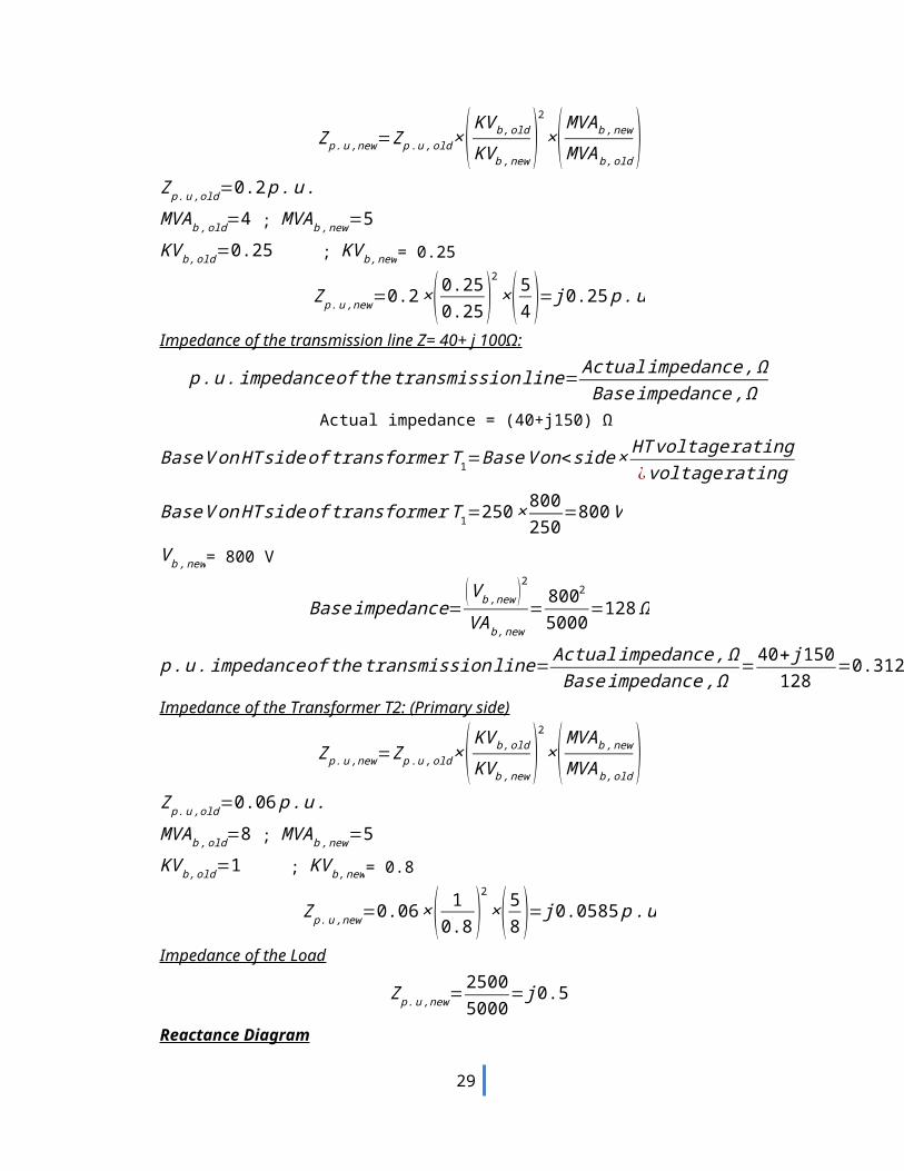
Impedance of the Transformer T1: (Primary side)
Zp . u ,new=Z p .u , old ×( KV b , old
KV b ,new)
2
×( MVAb ,new
MVAb , old)
Zp . u ,old=0.2 p . u . MVA b ,old=4 ; MVA b ,new=5KV b ,old=0.25 ; KV b ,new= 0.25
22
j 0.75
j 0.25 0.3125 + j 1.17 j 0.0585 j0.5j 1.0
Load
j 50Ω
T1 T2
2
G MT3 T4
4
Zp . u ,new=0.2×( 0.250.25 )
2
×( 54 )= j 0.25 p .u
Impedance of the transmission line Z= 40+ j 100Ω:
p .u . impedance of the transmissionline= Actual impedance , ΩBase impedance , Ω
Actual impedance = (40+j150) Ω
Base V on HT side of transformer T 1=Base V on<side× HT voltage rating¿ voltage rating
Base V on HT side of transformerT 1=250 × 800250
=800 V
V b , new= 800 V
Base impedance=(V b ,new )2
VA b,new=
8002
5000=128 Ω
p .u . impedance of the transmissionline= Actual impedance , ΩBase impedance , Ω
=40+ j150128
=0.3125+ j 1.17 p . u
Impedance of the Transformer T2: (Primary side)
Zp . u ,new=Z p .u , old ×( KV b , old
KV b ,new)
2
×( MVAb ,new
MVAb , old)
Zp . u ,old=0.06 p . u . MVA b ,old=8 ; MVAb ,new=5KV b ,old=1 ; KV b ,new= 0.8
Zp . u ,new=0.06 ×( 10.8 )
2
×( 58 )= j 0.0585 p . u
Impedance of the Load
Zp . u ,new=25005000
= j0.5
Reactance Diagram
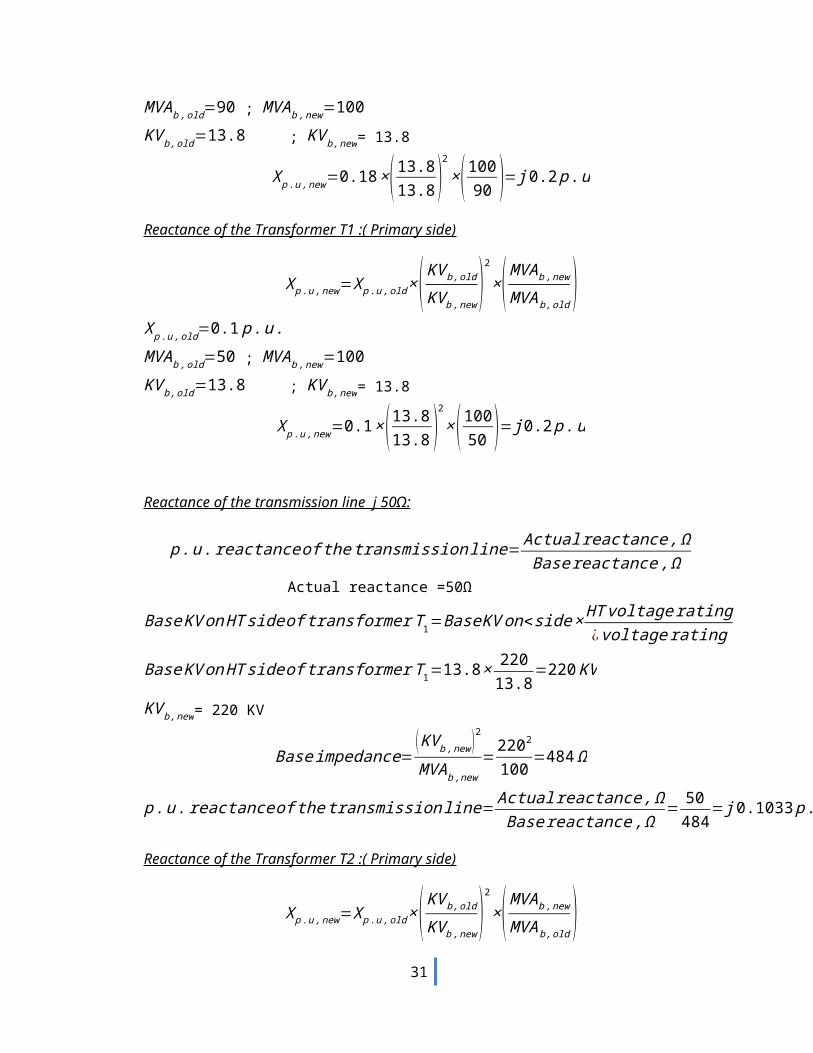
5. The single line diagram of a three phase power system is shown in fig. Select a common base of 100MVA and 13.8KV on the generator side. Draw per unit impedance diagram
23
G: 90MVA, 13.8KV, X=18% ; T1 :50MVA, 13.8/220KV, X=10%
T2:50MVA, 220/11KV, X=10% ; T3 :50MVA, 13.8/132KV, X=10%
T4:50MVA, 132/11KV, X=10% ; M : 80MVA, 10.45KV, X=20%
LOAD : 57MVA, 0.8 p.f lagging at 10.45 KV ; Line 1 = j 50Ω ; Line 2 = j 70Ω
Solution:Base MVA, MVAb, new = 100MVABase KV, KVb, new = 13.8KV
Reactance of the Generator G1:
X p . u ,new=X p .u , old ×( KV b , old
KV b ,new)
2
×( MVAb ,new
MVAb , old)
X p . u ,old=0.18 p . u . MVA b ,old=90 ; MVAb ,new=100KV b ,old=13.8 ; KV b ,new= 13.8
X p . u ,new=0.18×( 13.813.8 )
2
×(10090 )= j0.2 p .u
Reactance of the Transformer T1 :( Primary side)
X p . u ,new=X p .u , old ×( KV b , old
KV b ,new)
2
×( MVAb ,new
MVAb , old)
X p . u ,old=0.1 p . u . MVA b ,old=50 ; MVAb ,new=100KV b ,old=13.8 ; KV b ,new= 13.8
X p . u ,new=0.1×(13.813.8 )
2
×( 10050 )= j 0.2 p .u
Reactance of the transmission line j 50Ω:
24
p .u . reactance of thetransmissionline= Actual reactance , ΩBase reactance ,Ω
Actual reactance =50Ω
Base KV on HT side of transformer T 1=Base KV on<side × HT voltage rating¿voltage rating
Base KV on HT side of transformer T 1=13.8× 22013.8
=220 KV
KV b ,new= 220 KV
Base impedance=( KV b , new )2
MVA b ,new=
2202
100 =484 Ω
p .u . reactance of thetransmissionline= Actual reactance , ΩBase reactance ,Ω
= 50484
= j 0.1033 p . u
Reactance of the Transformer T2 :( Primary side)
X p . u ,new=X p .u , old ×( KV b , old
KV b ,new)
2
×( MVAb ,new
MVAb , old)
X p . u ,old=0.1 p . u . MVA b ,old=50 ; MVAb ,new=100KV b ,old=220 ; KV b ,new= 220
X p . u ,new=0.1×( 220220 )
2
×( 10050 )= j 0.2 p .u
Reactance of the Transformer T3 :( Primary side)
X p . u ,new=X p .u , old ×( KV b , old
KV b ,new)
2
×( MVAb ,new
MVAb , old)
X p . u ,old=0.1 p . u . MVA b ,old=50 ; MVAb ,new=100KV b ,old=13.8 ; KV b ,new= 13.8
X p . u ,new=0.1×(13.813.8 )
2
×( 10050 )= j 0.2 p .u
Reactance of the transmission line j 70Ω:
p .u . reactance of thetransmissionline= Actual reactance , ΩBase reactance ,Ω
Actual reactance =70Ω
Base KV on HT side of transformer T 3=Base KV on<side × HT voltage rating¿voltagerating
Base KV on HT side of transformer T 3=13.8 × 13213.8
=132 KV
25
KV b ,new= 132KV
Base impedance=( KV b , new )2
MVA b ,new=
1322
100 =174.24 Ω
p .u . reactance of thetransmissionline= Actual reactance , ΩBase reactance ,Ω
= 70174.24
= j 0.4017 p .u
Reactance of the Transformer T4 :( Primary side)
X p . u ,new=X p .u , old ×( KV b , old
KV b ,new)
2
×( MVA b ,new
MVAb , old)
X p . u ,old=0.1 p . u . MVA b ,old=50 ; MVA b ,new=100KV b ,old=132 ; KV b ,new= 132
X p . u ,new=0.1×(132132 )
2
×( 10050 )= j 0.2 p . u
Reactance of the Motor M:
X p . u ,new=X p .u , old ×( KV b , old
KV b ,new)
2
×( MVA b ,new
MVAb , old)
X p . u ,old=0.2 p . u . MVAb ,old=80 ; MVA b ,new=100KV b ,old=10.45 ; KV b ,new= ?
Base KV on<side of transformer T 4=Base KV on HT side × ¿ voltage ratingHT voltage rating
Base KV on<side of transformer T 4=132 × 11132
=11 KV
KV b ,new= 11KV
X p . u ,new=0.2×( 10.4511 )
2
×( 10080 )= j 0.22565 p . u
The load is at 0.8 p.f lagging is given bySL (3 ϕ )=57∠36.87 ˚
Load impedance is given by
ZL=(V L−L )2
SL3 ϕ¿ =
10.452
57∠36.87 ˚ =(1.532+ j1.1495)Ω
Base impedance for the load is
Base impedance=( KV b , new )2
MVA b ,new=
112
100=1.21 Ω
p .u . reactance of thetransmissionline= Actual reactance , ΩBase reactance ,Ω
=1.532+ j1.14951.21
=(1.266+ j0.95) p .u
Reactance Diagram
26
UNIT-II
POWER FLOW ANALYSIS
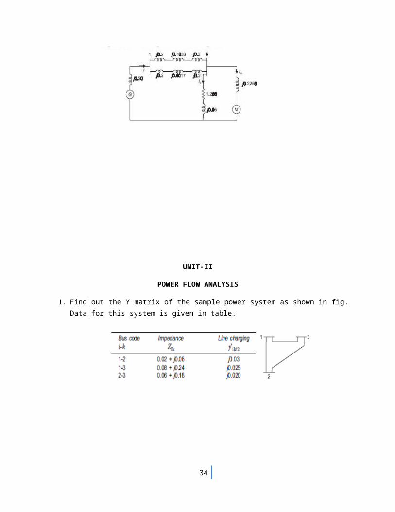
1. Find out the Y matrix of the sample power system as shown in fig. Data for this system is given in table.
27
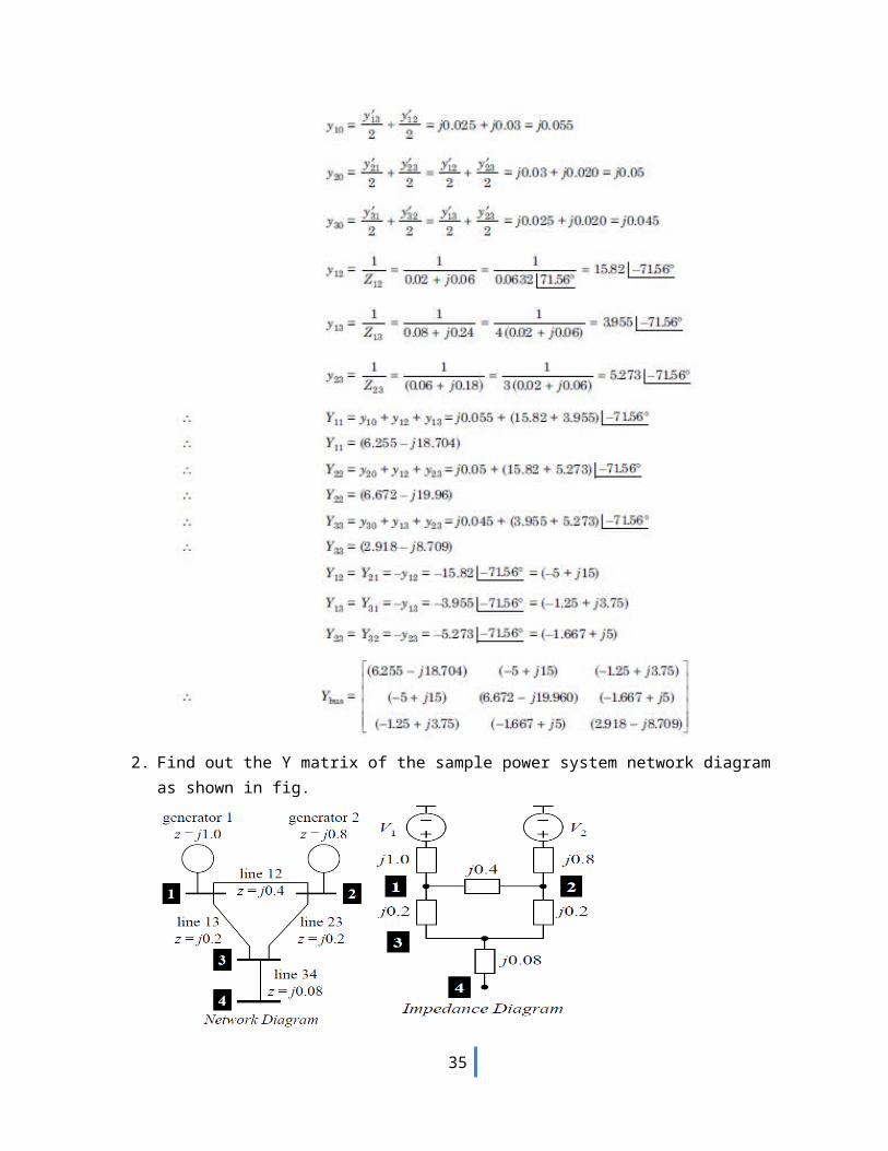
2. Find out the Y matrix of the sample power system network diagram as shown in fig.
28
0.02+j0.04
0.0125+j0.0250.01+j0.03
1 2
3
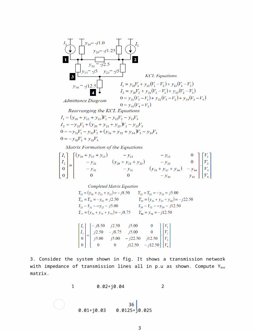
3. Consider the system shown in fig. It shows a transmission network with impedance of transmission lines all in p.u as shown. Compute Ybus matrix.
29
y12 = 10 - j 20 y13 = 10 - j 30 y32 = 16 - j 32
Ybus = [ 20− j50 −10+ j 20 −10+ j 30−10+ j 20 26− j52 −16+ j 32−10+ j 30 −16+ j 32 26− j 62 ]
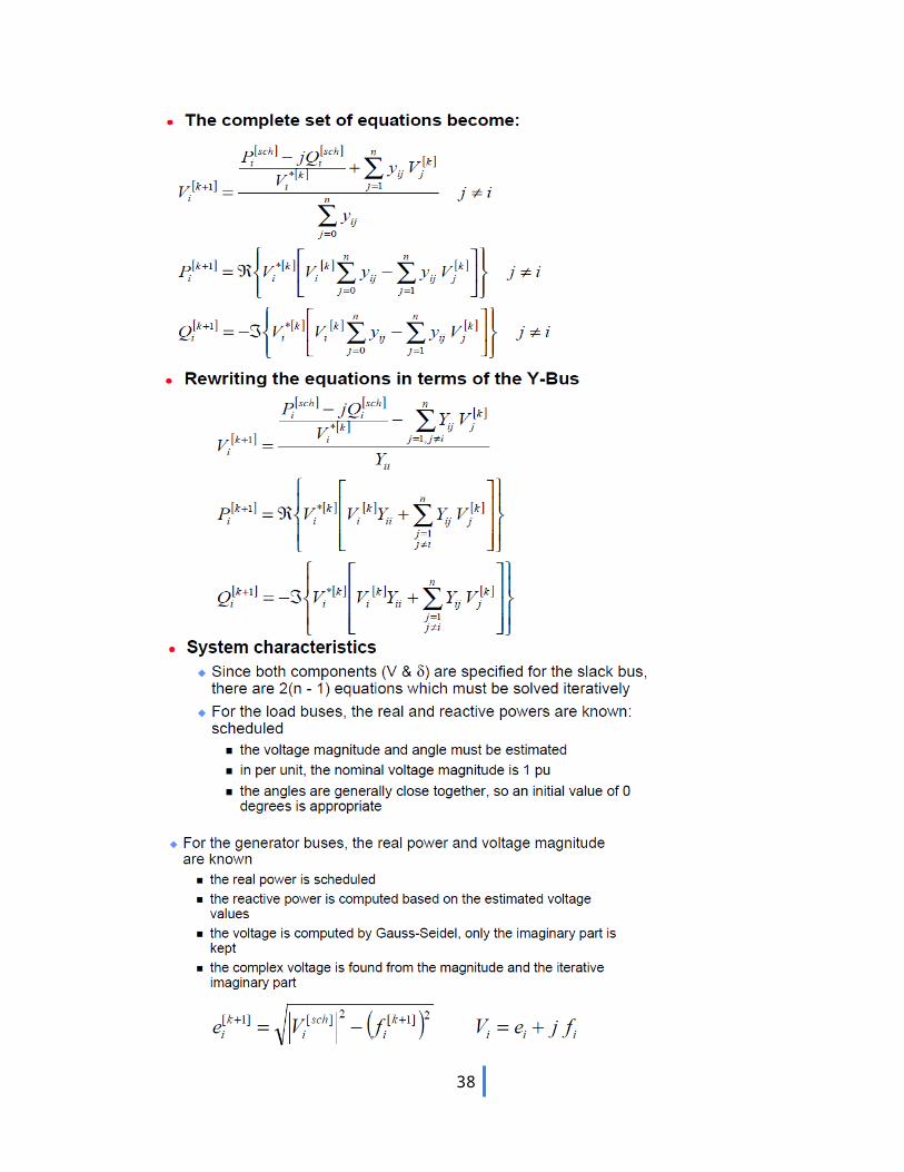
4. Explain Gauss seidel load flow problem.
30
31
5. The following is the system data for a load flow solution. Determine the voltages at the end of first iteration using Gauss-Seidel method. Take α=1.6 .
The line admittances:
Bus code Admittance1-2 2-j8.01-3 1-j4.02-3 0.666-j2.6642-4 1-j4.03-4 2-j8.0
The schedule of active and reactive powers:
Bus code P in p.u Q in p.u V in p.u Remarks1 - - 1.06 Slack2 0.5 0.2 1+j0.0 PQ3 0.4 0.3 1+j0.0 PQ4 0.3 0.1 1+j0.0 PQ
Solution
Y bus [3− j12 −2+ j 8 −1+ j 4 0−2+ j 8 3.666− j 14.664 −0.666+ j 2.664 −1+ j 4−1+ j 4 −0.666+ j 2.664 3.666− j 14.664 −2+ j8
0 −1+ j 4 −2+ j 8 3− j 12 ]
V 21 =
1Y 22 [ P2− j Q2
V 2¿ −Y 21V 1
0−Y 23 V 30−Y 24 V 4
O]V 2
1 = 1
3.666− j14.664 [−0.5+ j0.21− j 0.0
−1.06 (−2+ j8 )−1.0 (−0.666+ j2.6664 )−(−1+ j 4 ) 1.0]= 1.01187-j0.02888
V21
acc = (1.0+j0.0)+1.6(1.01187-j0.02888-1.0-j0.0) = 1.01899-j0.046208
V31
= 0.994119-j0.029248 ; V31
acc = 0.99059-j0.0467968
V41
= 0.9716032-j0.064684 ; V41
acc = 0.954565-j0.1034944
32
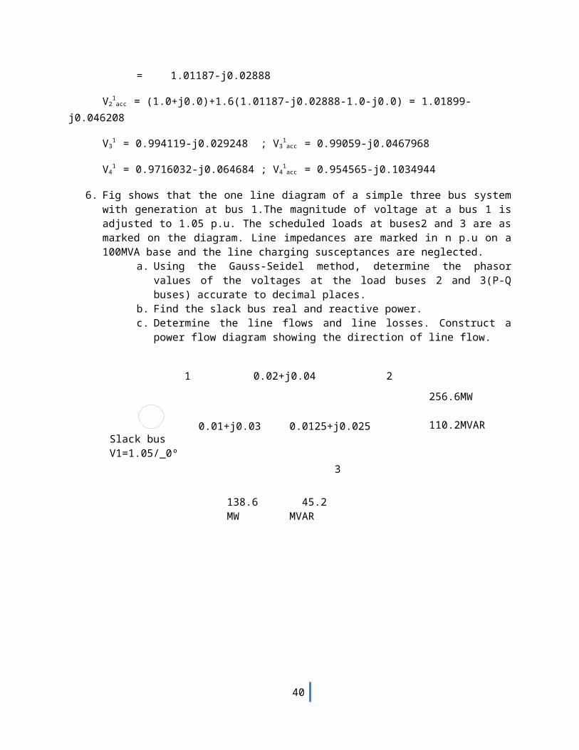
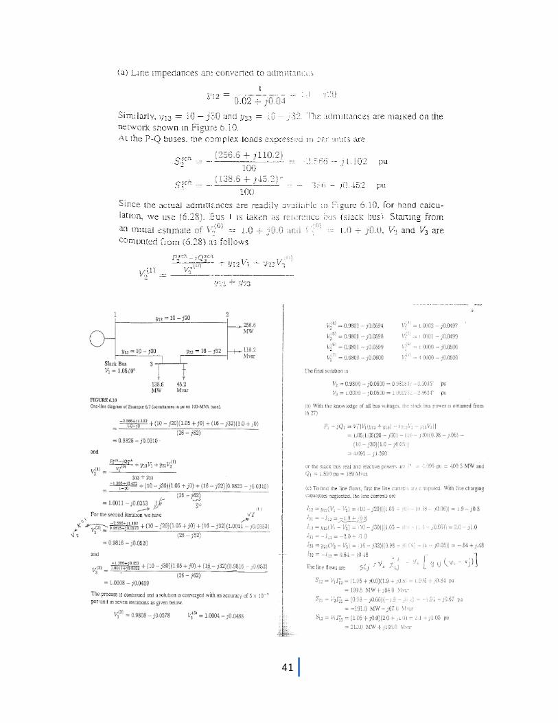
1 0.02+j0.04 2
0.01+j0.03 0.0125+j0.025Slack busV1=1.05/_0º
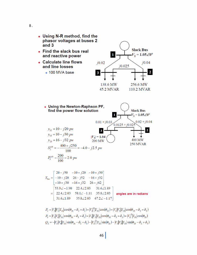
138.6 45.2MW MVAR
3
256.6MW
110.2MVAR
6. Fig shows that the one line diagram of a simple three bus system with generation at bus 1.The magnitude of voltage at a bus 1 is adjusted to 1.05 p.u. The scheduled loads at buses2 and 3 are as marked on the diagram. Line impedances are marked in n p.u on a 100MVA base and the line charging susceptances are neglected.
a. Using the Gauss-Seidel method, determine the phasor values of the voltages at the load buses 2 and 3(P-Q buses) accurate to decimal places.
b. Find the slack bus real and reactive power.c. Determine the line flows and line losses. Construct a power flow diagram showing
the direction of line flow.
33
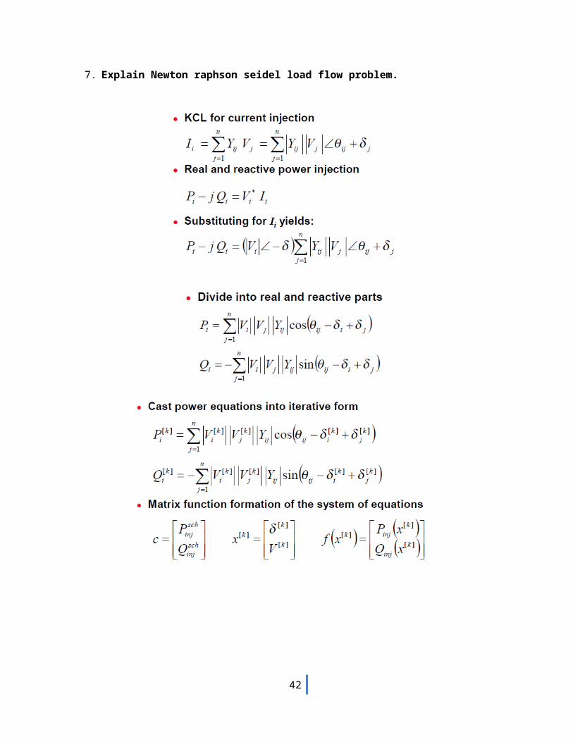
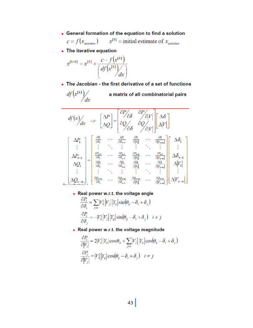
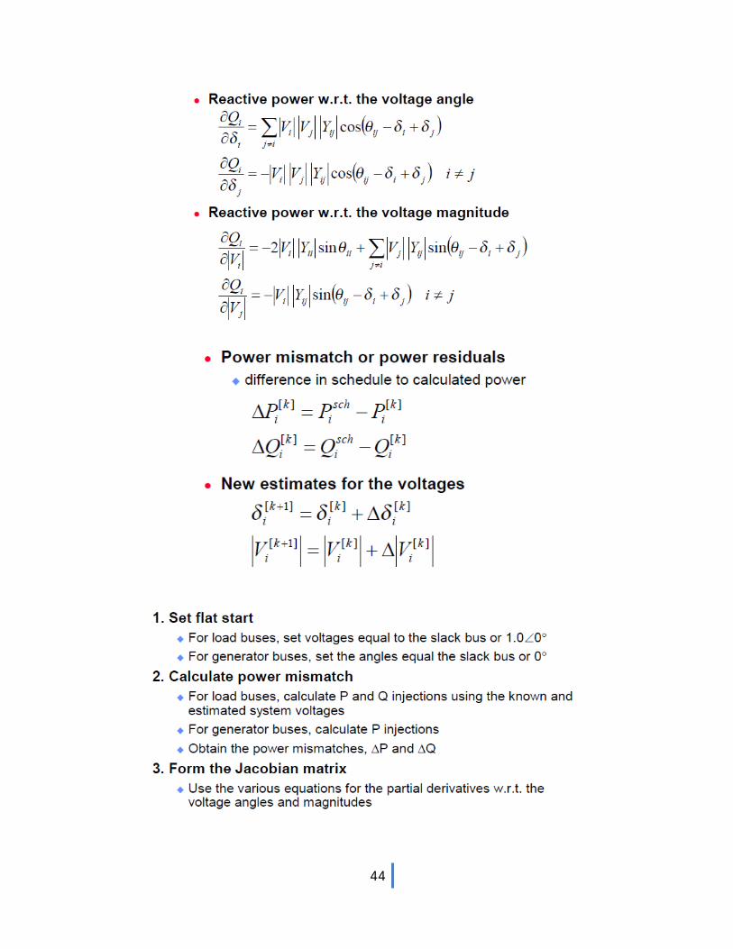
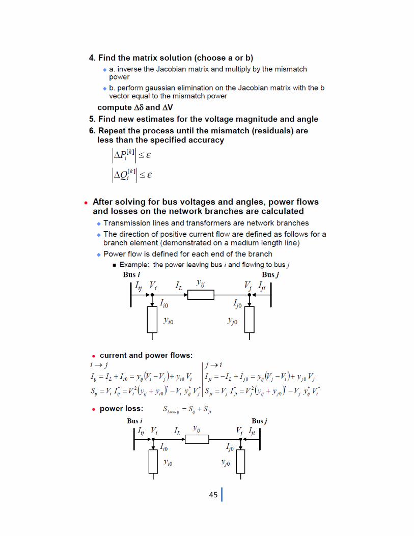
7. Explain Newton raphson seidel load flow problem.
34
35
36
37
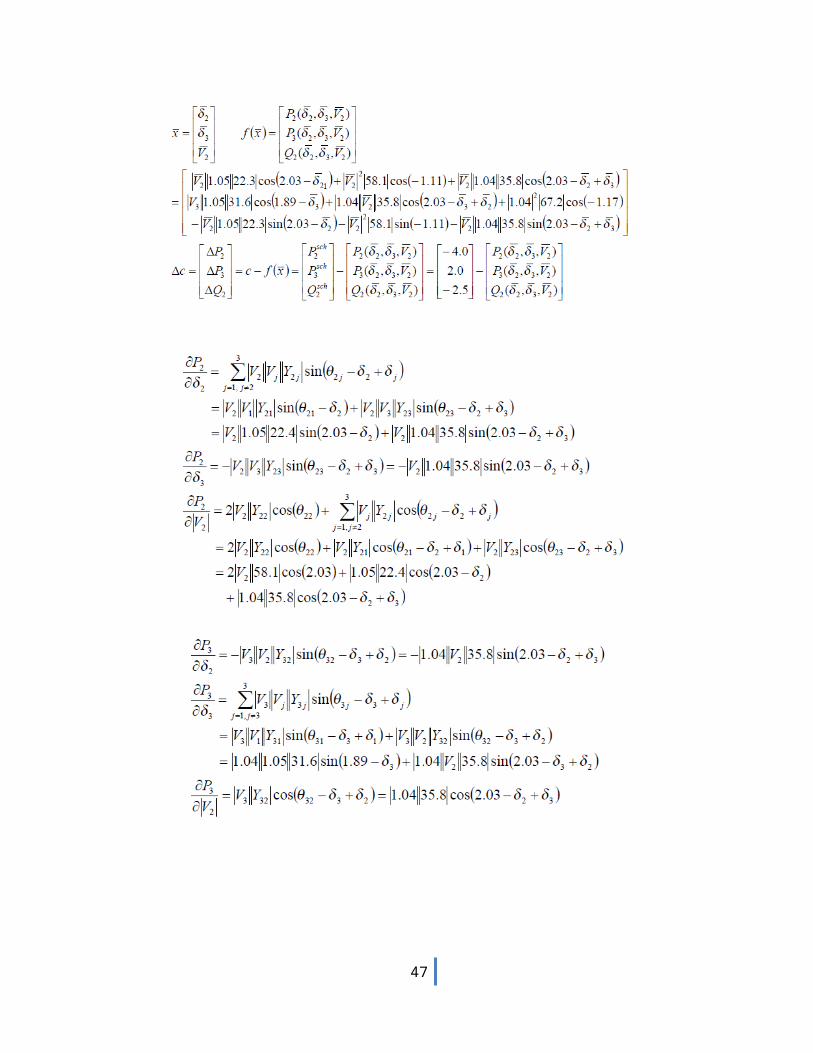
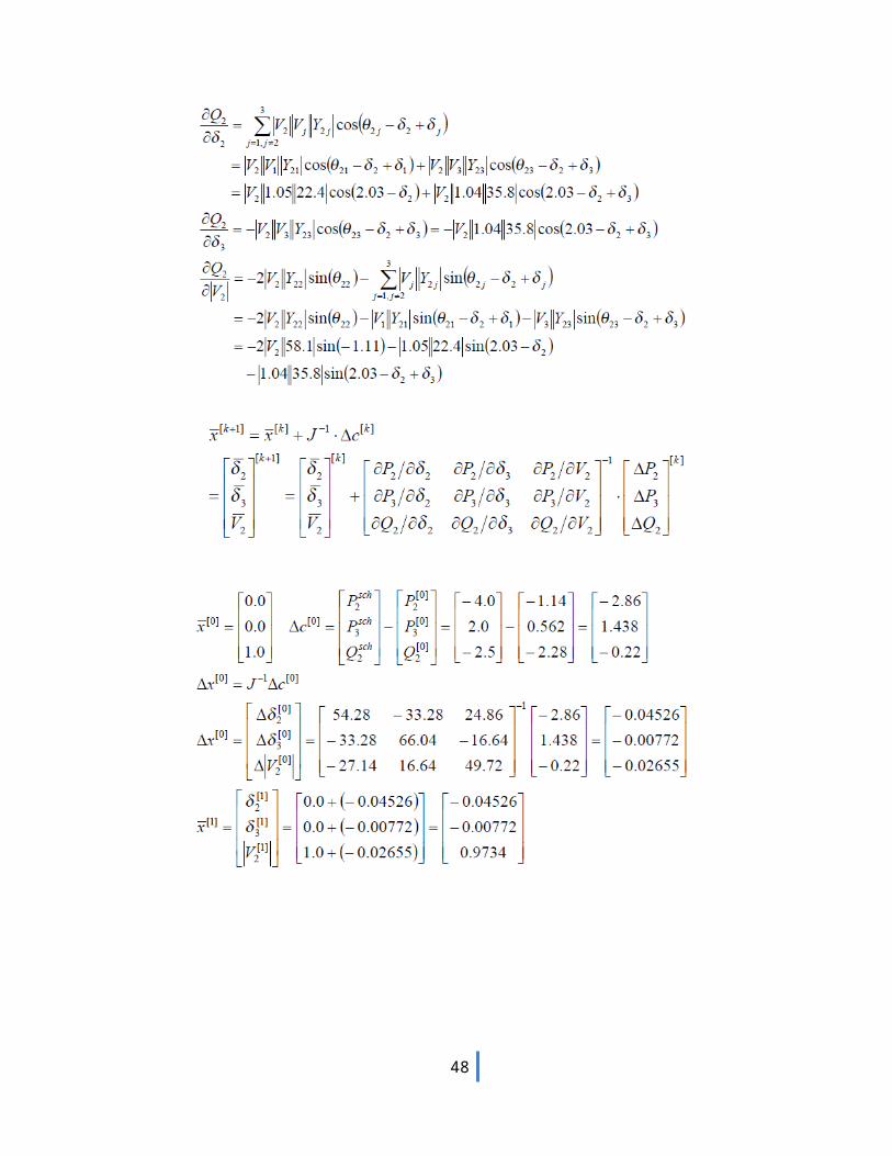
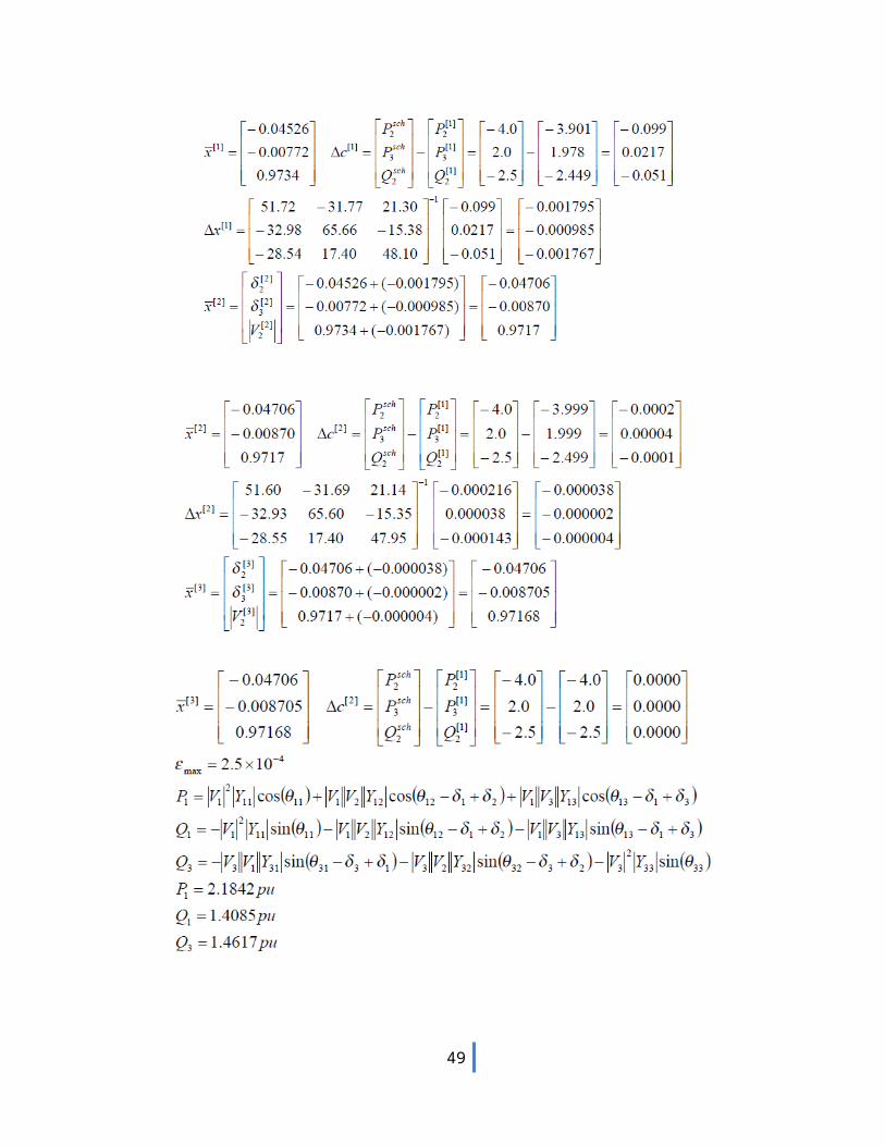
8.
38
39
40
41
42
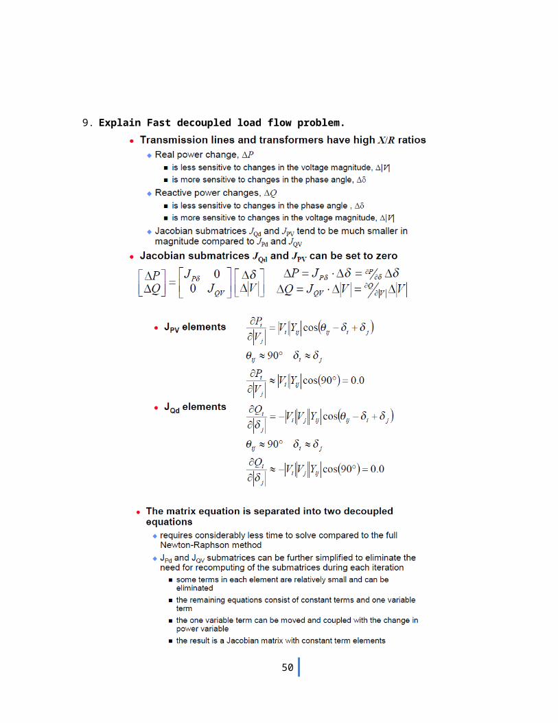
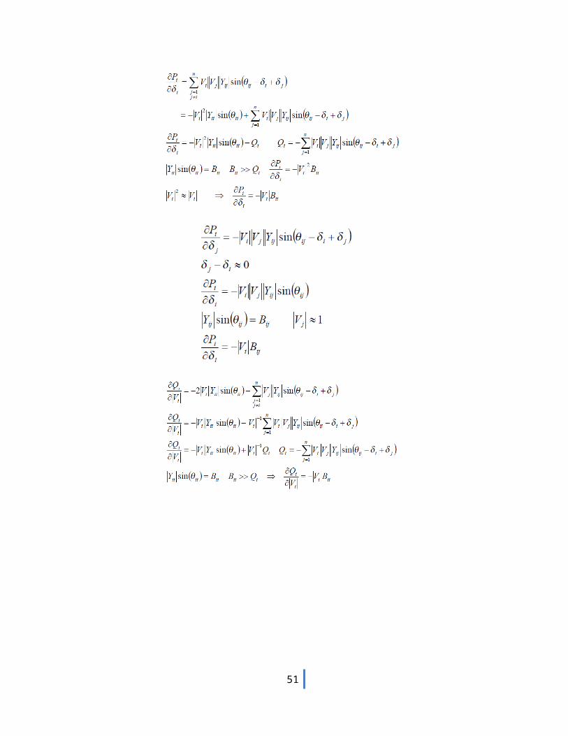
9. Explain Fast decoupled load flow problem.
43
44
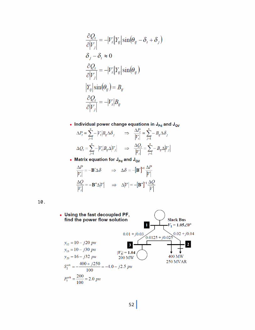
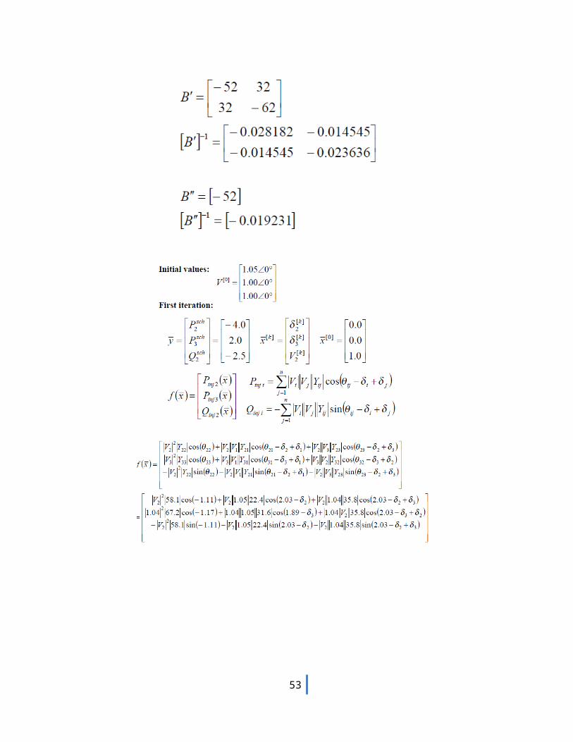
10.
45
46
47
UNIT-III
FAULT ANALYSIS - BALANCED FAULT
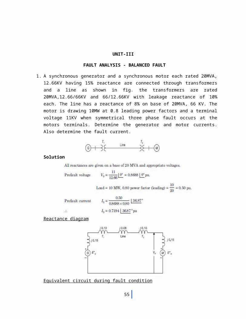
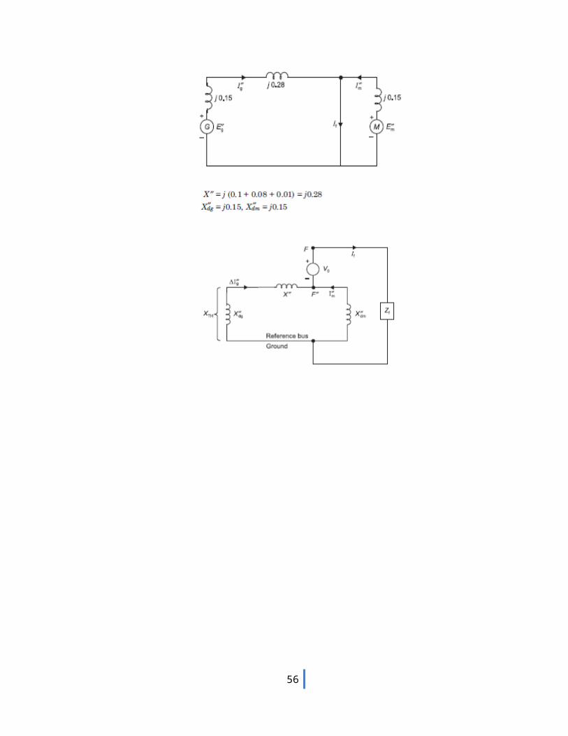
1. A synchronous generator and a synchronous motor each rated 20MVA, 12.66KV having 15% reactance are connected through transformers and a line as shown in fig. the transformers are rated 20MVA,12.66/66KV and 66/12.66KV with leakage reactance of 10% each. The line has a reactance of 8% on base of 20MVA, 66 KV. The motor is drawing 10MW at 0.8 leading power factors and a terminal voltage 11KV when symmetrical three phase fault occurs at the motors terminals. Determine the generator and motor currents. Also determine the fault current.
Solution
Reactance diagram
Equivalent circuit during fault condition
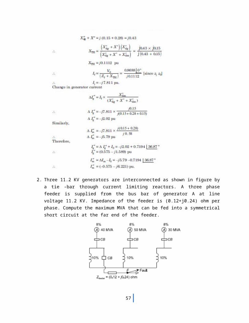
48
2. Three 11.2 KV generators are interconnected as shown in figure by a tie -bar through current
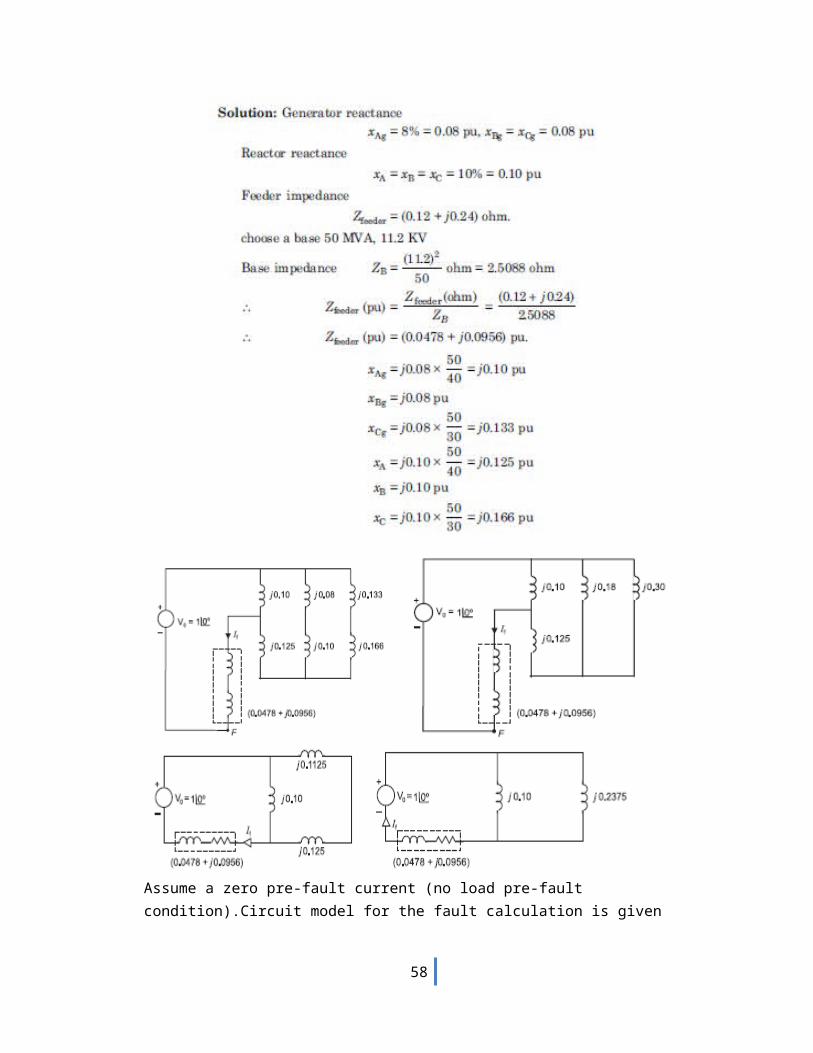
limiting reactors. A three phase feeder is supplied from the bus bar of generator A at line voltage 11.2 KV. Impedance of the feeder is (0.12+j0.24) ohm per phase. Compute the maximum MVA that can be fed into a symmetrical short circuit at the far end of the feeder.
49
50
Assume a zero pre-fault current (no load pre-fault condition).Circuit model for the fault calculation is given
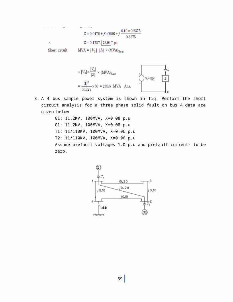
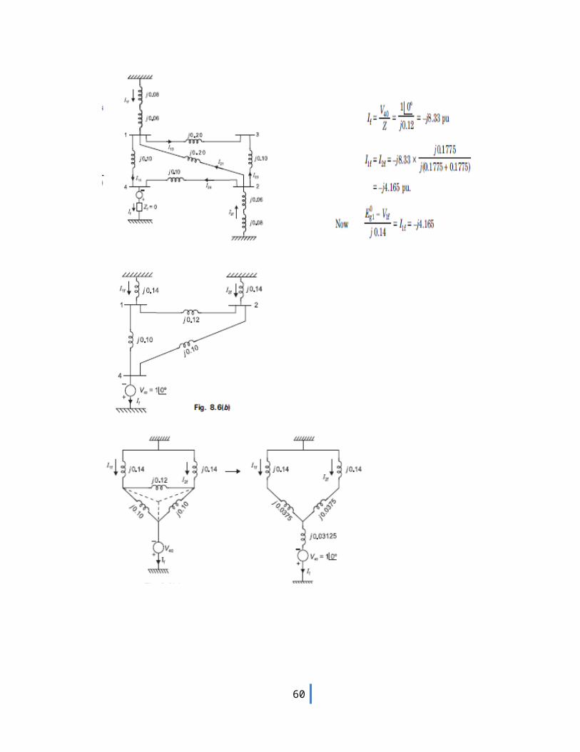
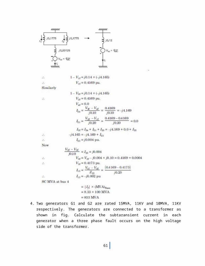
3. A 4 bus sample power system is shown in fig. Perform the short circuit analysis for a three phase solid fault on bus 4.data are given below
G1: 11.2KV, 100MVA, X=0.08 p.uG1: 11.2KV, 100MVA, X=0.08 p.uT1: 11/110KV, 100MVA, X=0.06 p.uT2: 11/110KV, 100MVA, X=0.06 p.uAssume prefault voltages 1.0 p.u and prefault currents to be zero.
51
52
53
4. Two generators G1 and G2 are rated 15MVA, 11KV and 10MVA, 11KV respectively. The generators are connected to a transformer as shown in fig. Calculate the subtaransient current in each generator when a three phase fault occurs on the high voltage side of the transformer.
54
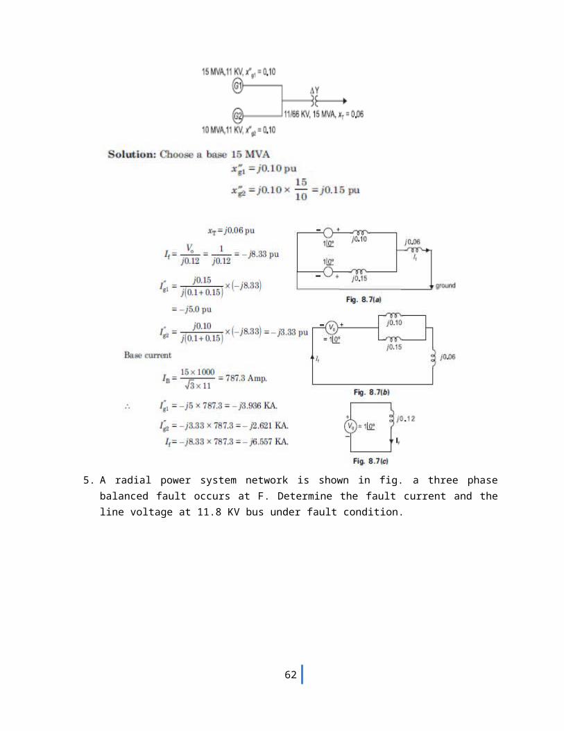
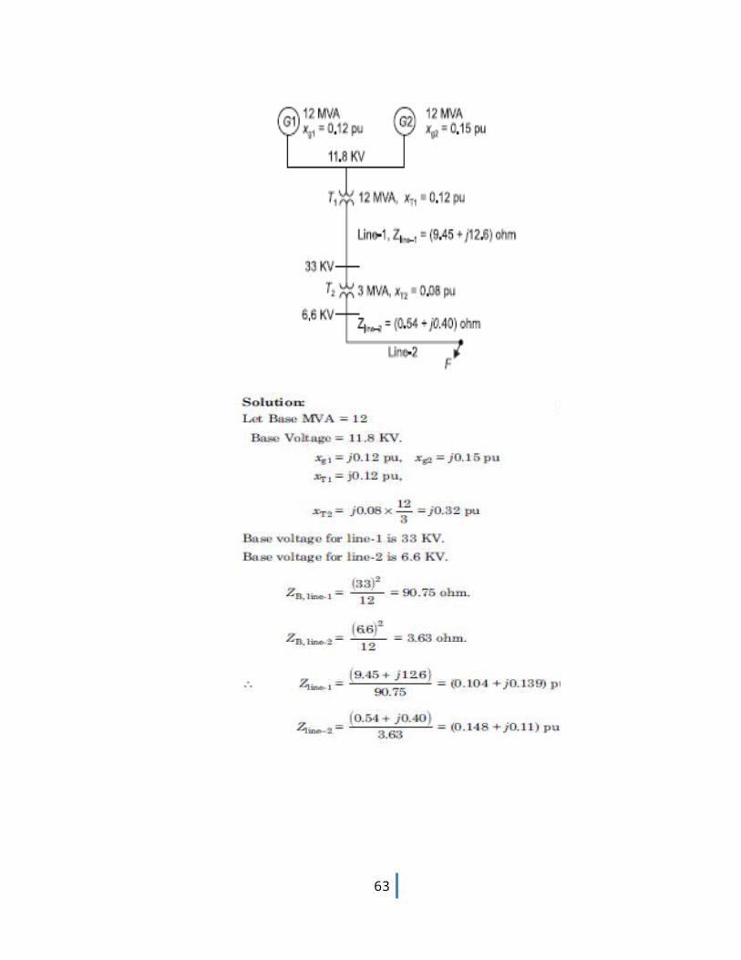
5. A radial power system network is shown in fig. a three phase balanced fault occurs at F. Determine the fault current and the line voltage at 11.8 KV bus under fault condition.
55
56
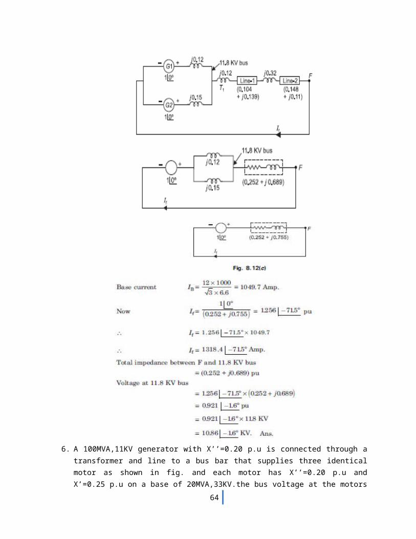
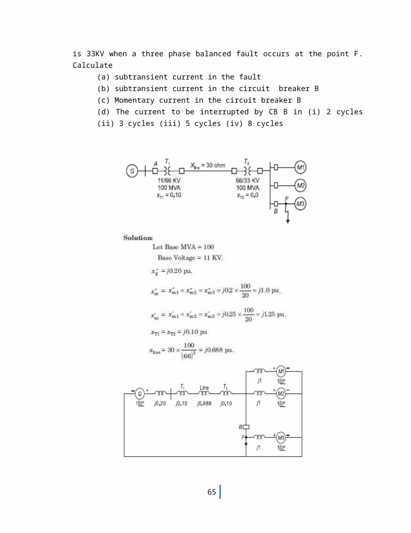
6. A 100MVA,11KV generator with X’’=0.20 p.u is connected through a transformer and line to a bus bar that supplies three identical motor as shown in fig. and each motor has X’’=0.20 p.u and X’=0.25 p.u on a base of 20MVA,33KV.the bus voltage at the motors is 33KV when a three phase balanced fault occurs at the point F. Calculate
(a) subtransient current in the fault(b) subtransient current in the circuit breaker B(c) Momentary current in the circuit breaker B(d) The current to be interrupted by CB B in (i) 2 cycles (ii) 3 cycles (iii) 5 cycles (iv) 8 cycles
57
58
59
7.
60
8. Obtain impedance matrix ZBUS for shown in figure.
61
9. Obtain impedance matrix ZBUS for shown in figure
62
63
UNIT-IV
FAULT ANALYSIS - SYMMETRICAL COMPONENETS
AND UNBALANCED FAULT
9. The phase voltage across a certain load are given as
Compute positive, negative and zero sequence component of voltage.
Solution:
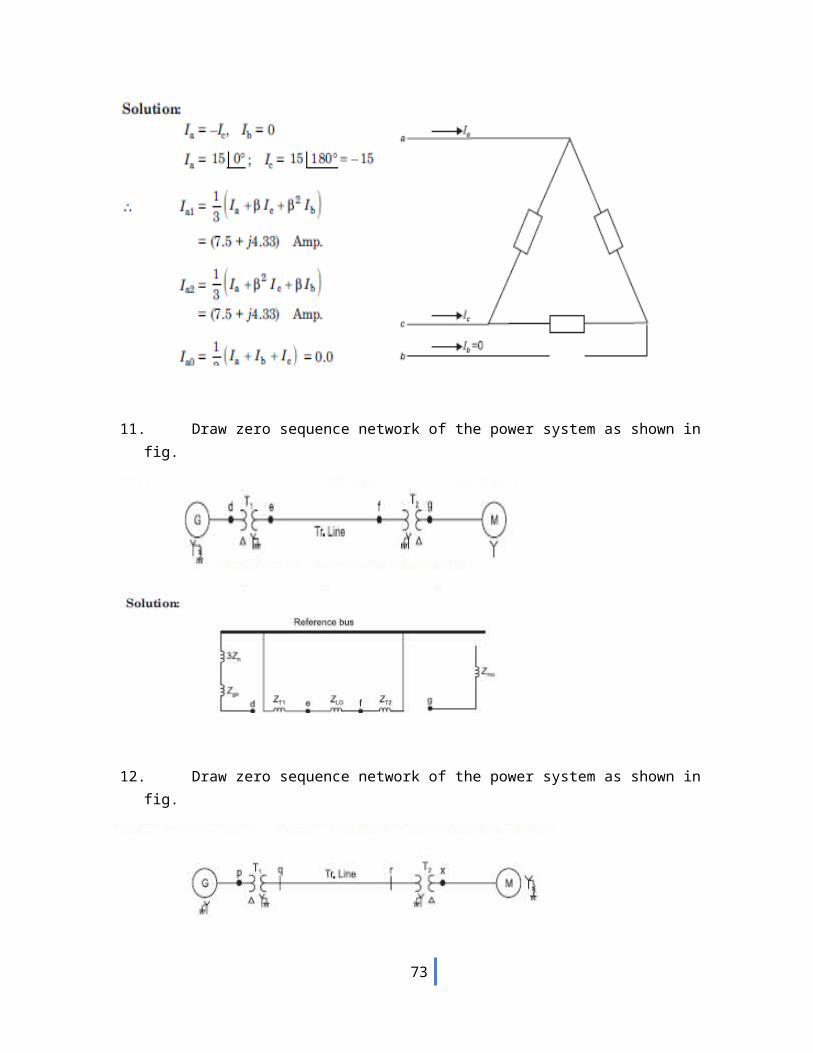
10. A balanced delta connected load is connected to a three phase system and supplied to it is a current of 15 amps. If the fuse is one of the lines melts, compute the symmetrical components of line currents.
64
11. Draw zero sequence network of the power system as shown in fig.
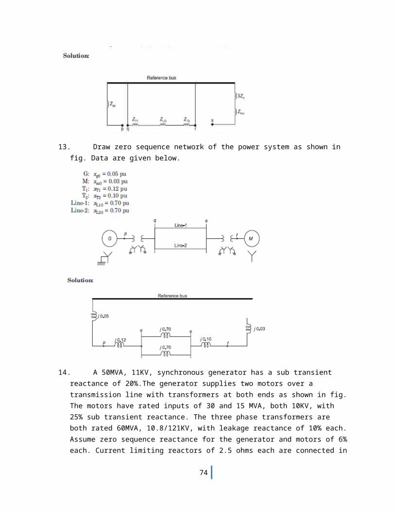
12. Draw zero sequence network of the power system as shown in fig.
65
13. Draw zero sequence network of the power system as shown in fig. Data are given below.
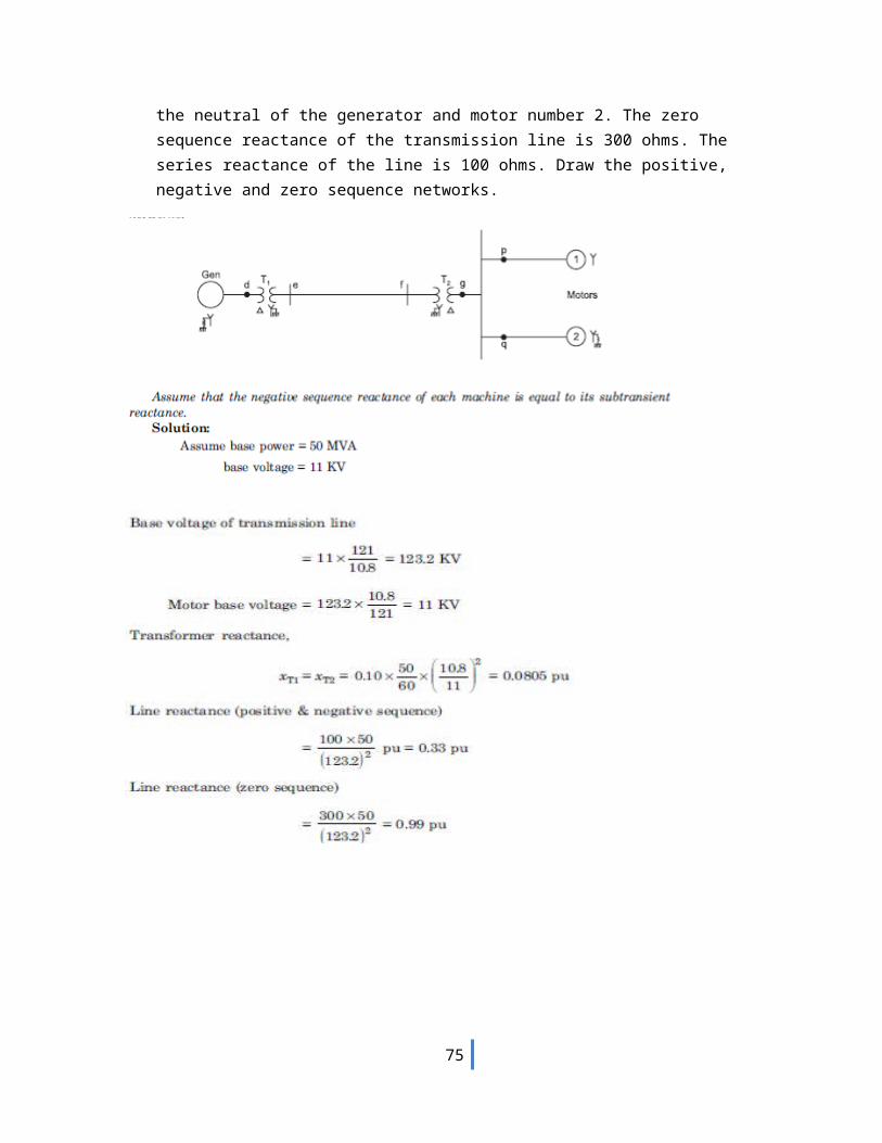
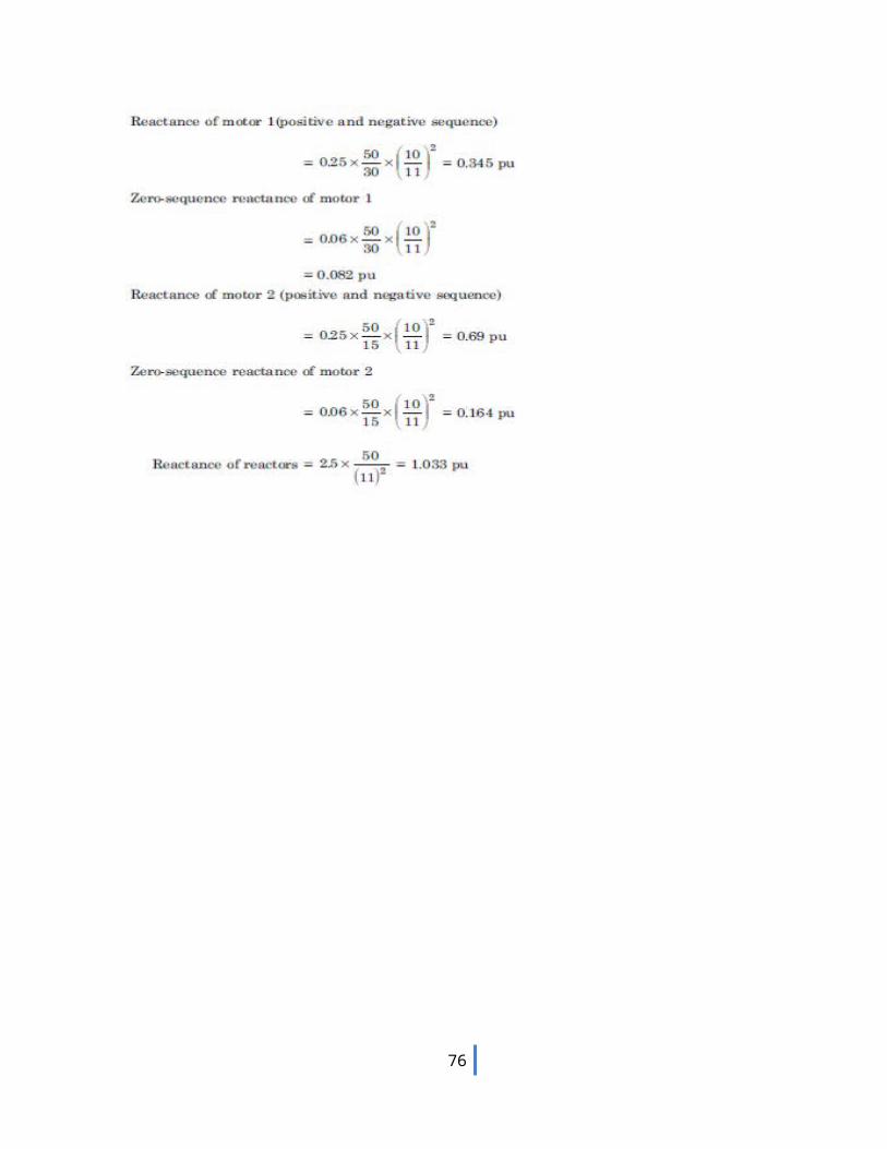
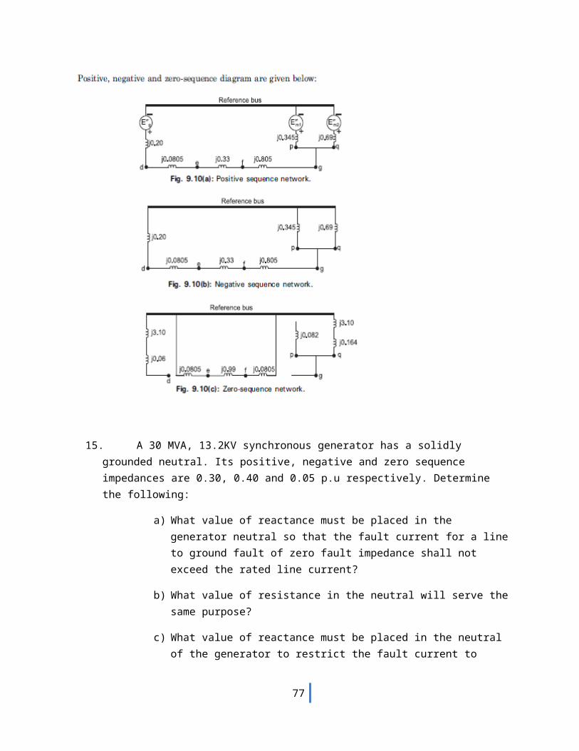
14. A 50MVA, 11KV, synchronous generator has a sub transient reactance of 20%.The generator supplies two motors over a transmission line with transformers at both ends as shown in fig. The motors have rated inputs of 30 and 15 MVA, both 10KV, with 25% sub transient reactance. The three phase transformers are both rated 60MVA, 10.8/121KV, with leakage reactance of 10% each. Assume zero sequence reactance for the generator and motors of 6% each. Current limiting reactors of 2.5 ohms each are connected in the neutral of the generator and motor number 2. The zero sequence reactance of the transmission line is 300 ohms. The series reactance of the line is 100 ohms. Draw the positive, negative and zero sequence networks.
66
67

68
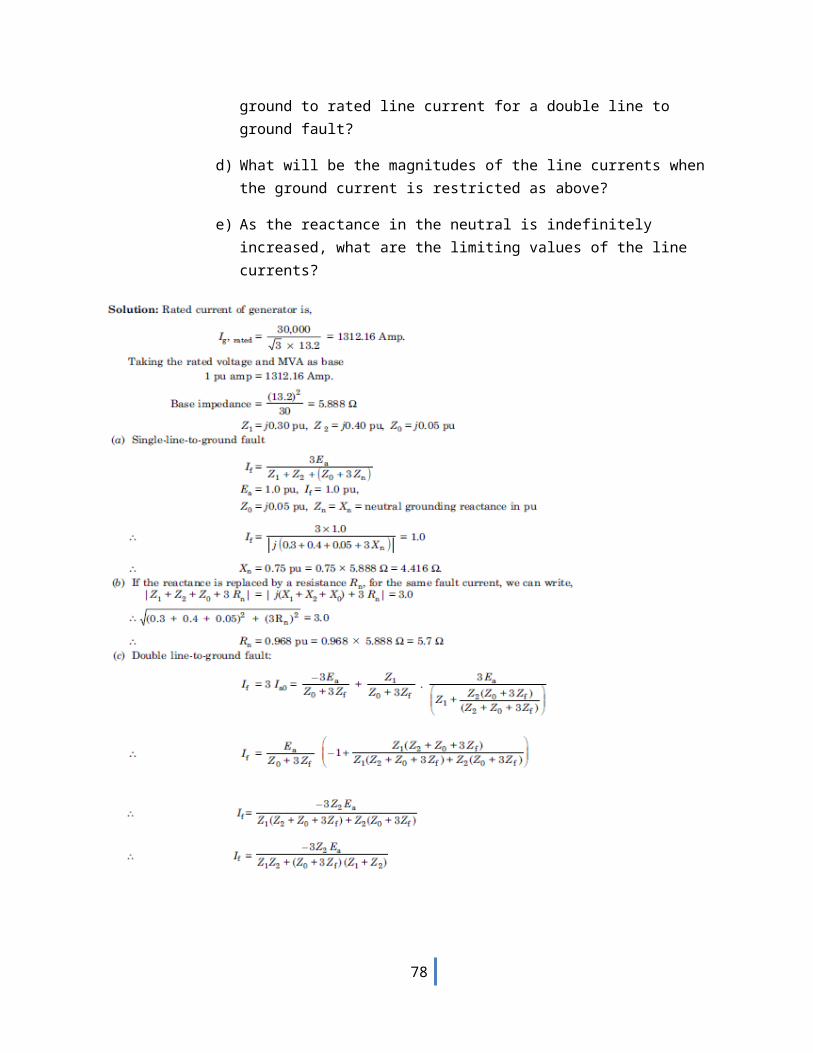
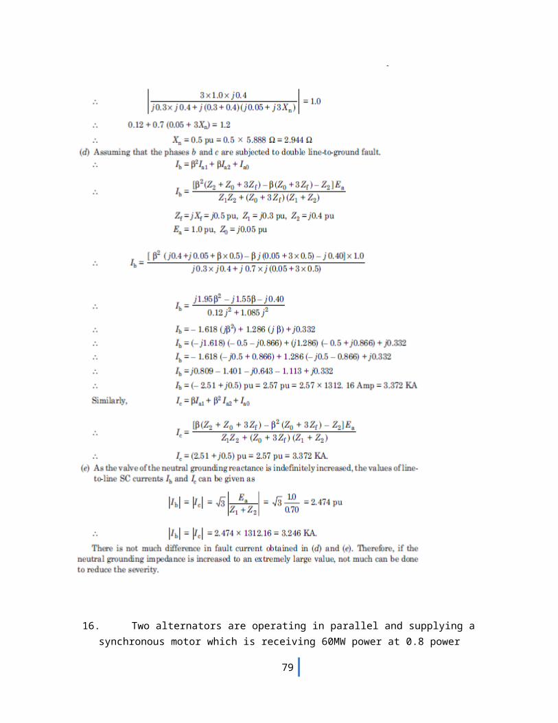
15. A 30 MVA, 13.2KV synchronous generator has a solidly grounded neutral. Its positive, negative and zero sequence impedances are 0.30, 0.40 and 0.05 p.u respectively. Determine the following:
a) What value of reactance must be placed in the generator neutral so that the fault current for a line to ground fault of zero fault impedance shall not exceed the rated line current?
b) What value of resistance in the neutral will serve the same purpose?
c) What value of reactance must be placed in the neutral of the generator to restrict the fault current to ground to rated line current for a double line to ground fault?
d) What will be the magnitudes of the line currents when the ground current is restricted as above?
69
e) As the reactance in the neutral is indefinitely increased, what are the limiting values of the line currents?
70

16. Two alternators are operating in parallel and supplying a synchronous motor which is receiving 60MW power at 0.8 power factor lagging at 6.0 KV. Single line diagram for this system is given in
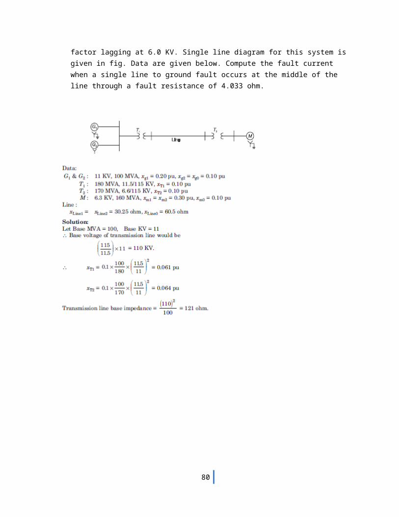
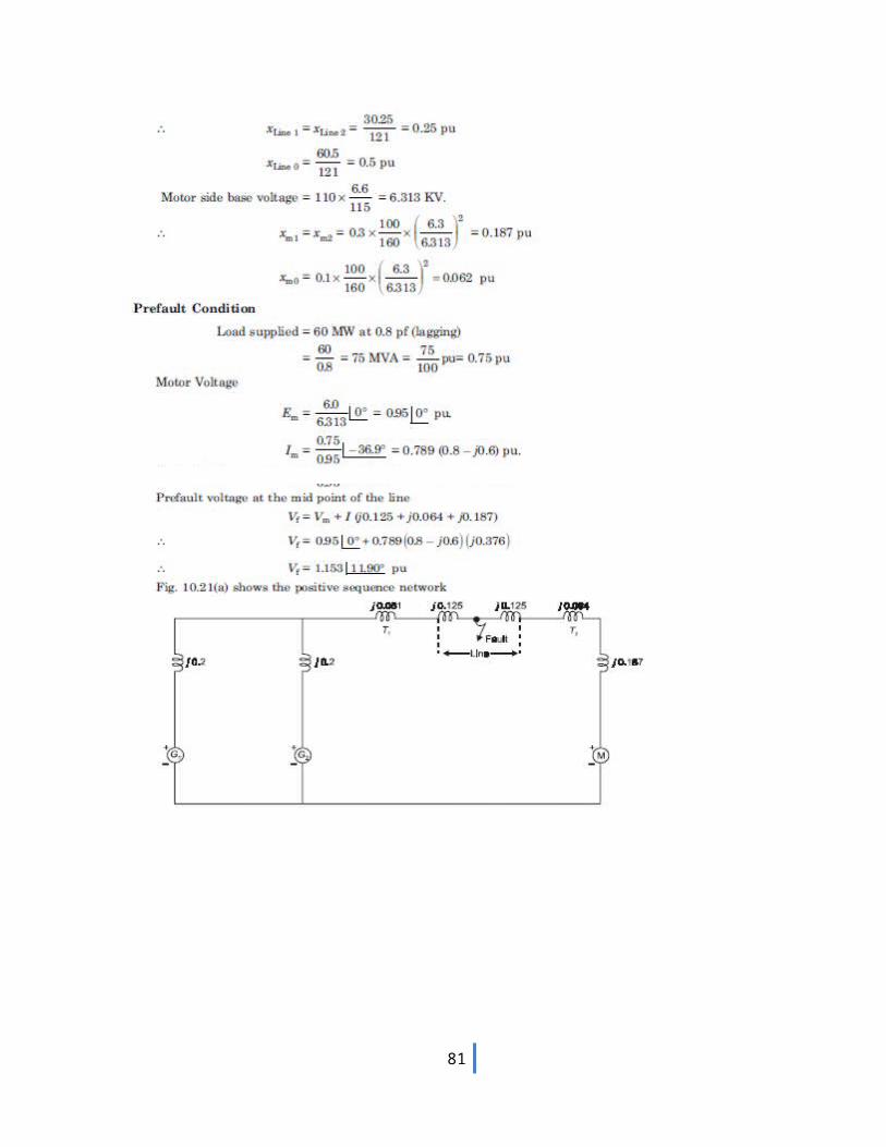
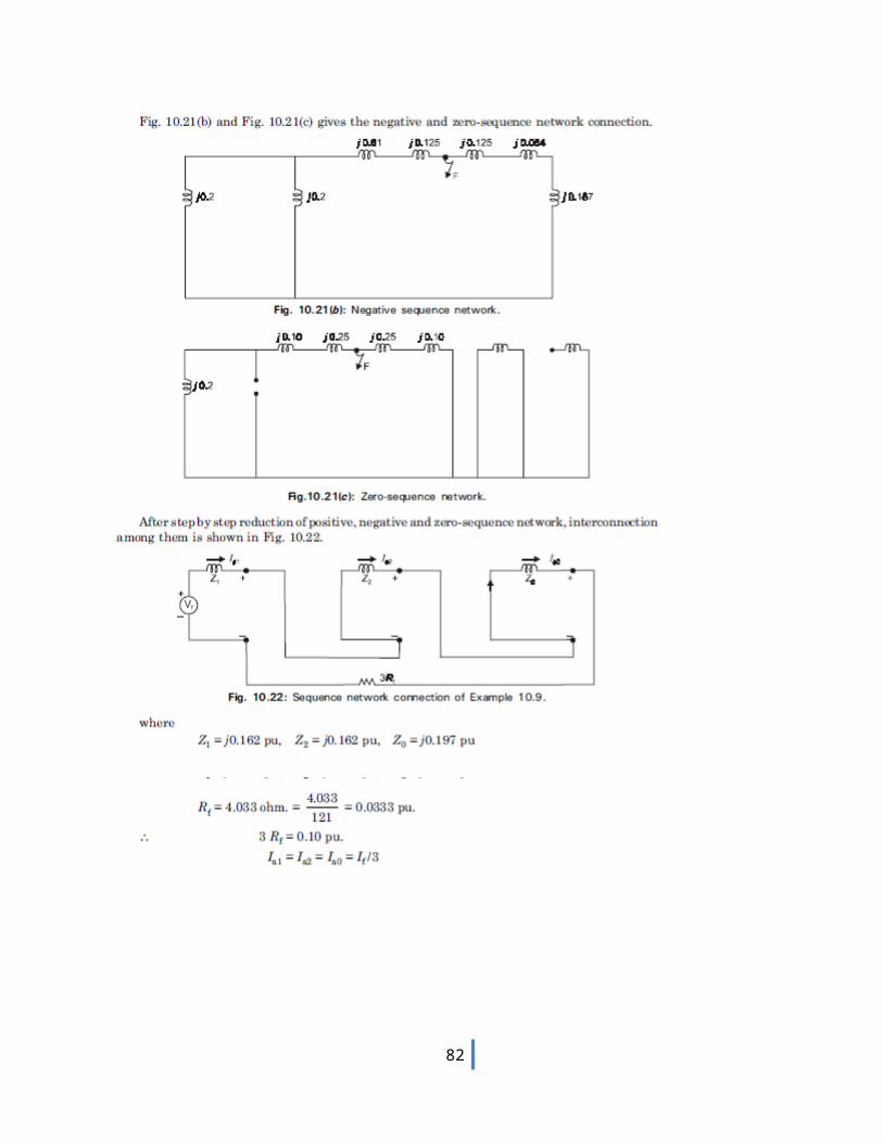
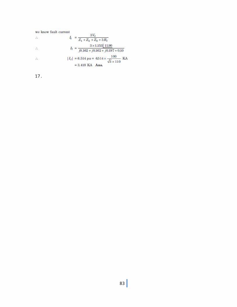
71
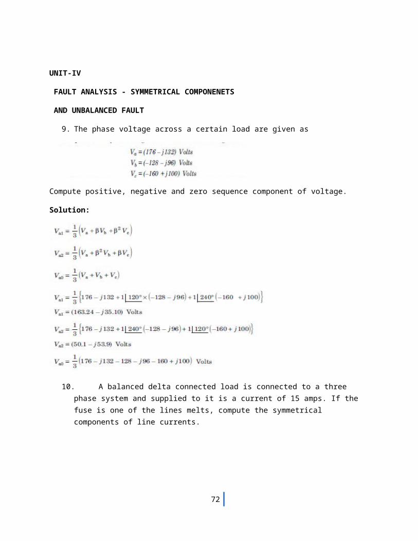
fig. Data are given below. Compute the fault current when a single line to ground fault occurs at the middle of the line through a fault resistance of 4.033 ohm.
72
73
74
17.
75
76
77
UNIT-V
POWER SYSTEM STABILITY
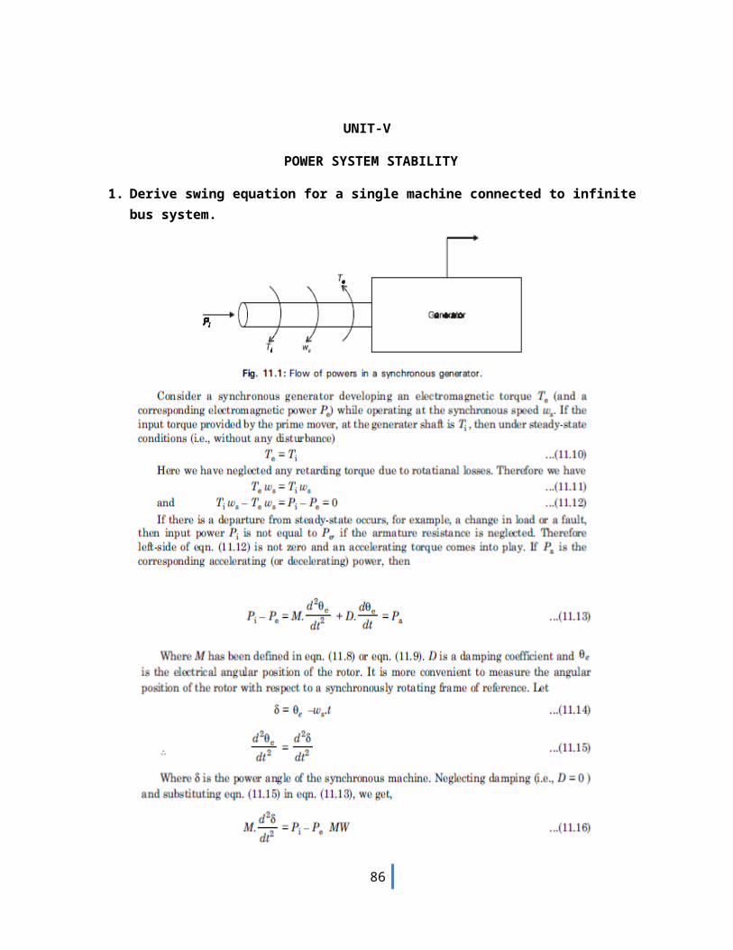
1. Derive swing equation for a single machine connected to infinite bus system.
78
2. A 400 MVA synchronous machine has H1=4.6 MJ/MVA and a 1200 MVA machines H2=3.0 MJ/MVA. Two machines operate in parallel in a power plant. Find out Heq relative to a 100MVA base.
79
3. A 100 MVA, two pole, 50Hz generator has moment of inertia 40 x 103 kg-m2.what is the energy stored in the rotor at the rated speed? What is the corresponding angular momentum? Determine the inertia constant h.
4. The sending end and receiving end voltages of a three phase transmission line at a 200MW load are equal at 230KV.The per phase line impedance is j14 ohm. Calculate the maximum steady state power that can be transmitted over the line.
5. Explain Equal area criterion in transient stability.
80
81
82
6. A single line diagram of a system is shown in fig. All the values are in per unit on a common base. The power delivered into bus 2 is 1.0 p.u at 0.80 power factor lagging. Obtain the power angle equation and the swing equation for the system. Neglect all losses.
83

7. Explain critical clearing angle and critical clearing time in transient stability.
84

85
86
87
8. A 50Hz synchronous generator capable of supplying 400MW of power is connected to a larger power system and is delivering 80MW when a three phase fault occurs at its terminals, determine (a) the time in which the fault must be cleared if the maximum power angle is to be -85˚ assume H=7MJ/MVA on a 100MVA base (b) the critical clearing angle.
88
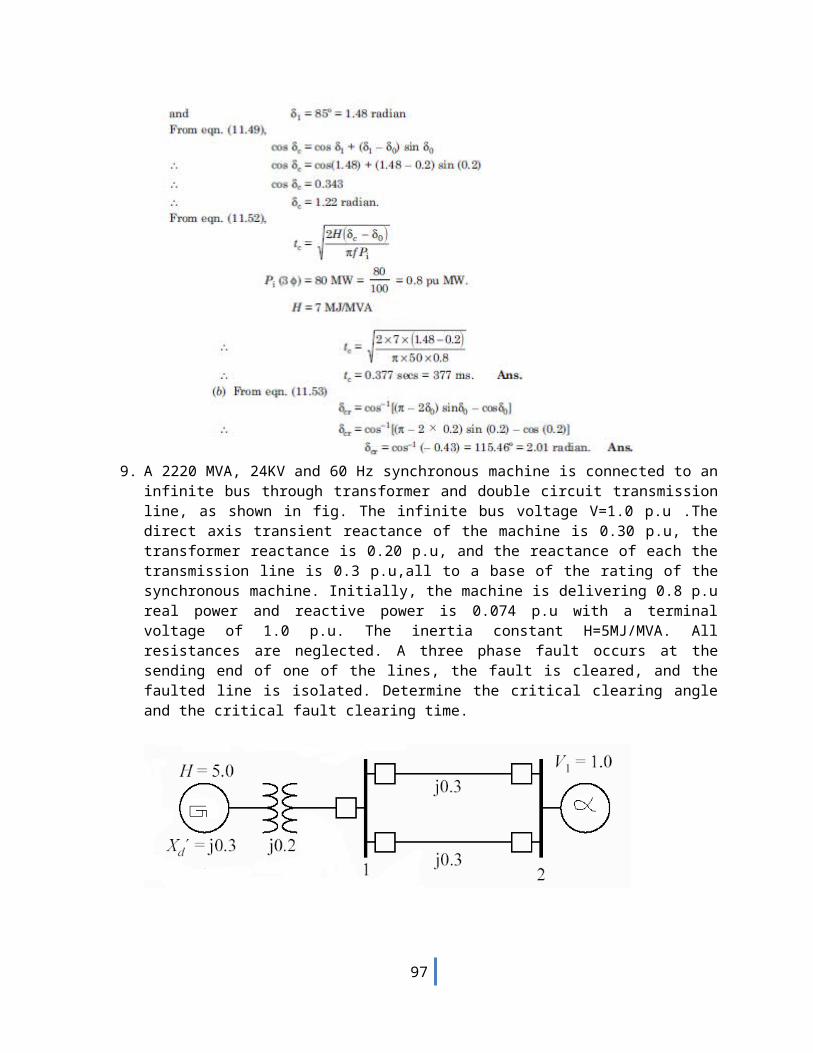
9. A 2220 MVA, 24KV and 60 Hz synchronous machine is connected to an infinite bus through transformer and double circuit transmission line, as shown in fig. The infinite bus voltage V=1.0 p.u .The direct axis transient reactance of the machine is 0.30 p.u, the transformer reactance is 0.20 p.u, and the reactance of each the transmission line is 0.3 p.u,all to a base of the rating of the synchronous machine. Initially, the machine is delivering 0.8 p.u real power and reactive power is 0.074 p.u with a terminal voltage of 1.0 p.u. The inertia constant H=5MJ/MVA. All resistances are neglected. A three phase fault occurs at the sending end of one of the lines, the fault is cleared, and the faulted line is isolated. Determine the critical clearing angle and the critical fault clearing time.
The current flowing into the infinite bus is I= S¿
V ¿ ¿P− jQ
V ¿
I= S¿
V ¿ ¿P− jQ
V ¿ =0.8− j0.0741.0
=0.8− j 0.074 p .u
The transfer reactance between internal voltage and the infinite bus before fault is
89
X = Xg +XT +Xtr.line
X = 0.3 + 0.2 +0.3/2 = 0.65The transient internal voltage is
E = V +j X I = 1.0+ (j0.65) (0.8- j0.074) = 1.17¿26.387
Since both lines are intact when the fault is cleared, the power angle equation before and after the fault is
Pmax sin δ=1.17 ×1.00.65
sin δ=1.8sin δ
The initial operating angle is given by 1.8 sin δ 0= 0.8δ0 = 26.388 = 0.46055 radδmax =180º - δ0 = 153.612 =2.681rad
Critical clearing angle cos δc=Pm
Pmax(δ max−δ0 )+cosδ max
cos δc=0.81.8
(2.681−0.46055 )+cos153.61=0.09106
δc = cos−1 0.09106=84.775=1.48
Critical clearing time tc =√ 2 H (δ C−δ 0 )π f 0 Pm
= √ 2 ×5 (1.48−0.46055)π ×60 × 0.8
= 0.26 second
10. A synchronous generator is connected to a large power system and supplying 0.45 pu MW of its maximum power capacity. A three phase fault occurs and the effective terminal voltage of the generator becomes 25% of its value before the fault. When the fault is cleared, generator is delivering 70% of the original maximum value. Determine the critical clearing angle.
90
11. Find the critical clearing angle of the power system shown in fig. for a three phase fault at the point F. Generator is supplying 1.0 p.u MW power under pre-fault condition.
91
92
12. What are the factors influencing transient stability?
93
13. What are the numerical integration methods of power system stability? Explain any one methods.
v. Point by point method or step by step methodvi. Euler method
vii. Modified Euler methodviii. Runge-Kutta method(R-K method)
Step by step method
94
95
96
97