viewpoint invariant exemplar-based 3d human …uncorrected proof 1 2 viewpoint invariant...
TRANSCRIPT
UN
CO
RR
EC
TED
PR
OO
F
1
2 Viewpoint invariant exemplar-based 3D human tracking
3 Eng-Jon Ong *, Antonio S. Micilotta, Richard Bowden, Adrian Hilton
4 Centre for Vision, Speech and Signal Processing, SEPS, University of Surrey, Guildford GU2 7XH, Surrey, UK
5 Received 16 February 2006; accepted 8 August 20066
7 Abstract
8 This paper proposes a clustered exemplar-based model for performing viewpoint invariant tracking of the 3D motion of a human9 subject from a single camera. Each exemplar is associated with multiple view visual information of a person and the corresponding
10 3D skeletal pose. The visual information takes the form of contours obtained from different viewpoints around the subject. The inclusion11 of multi-view information is important for two reasons: viewpoint invariance; and generalisation to novel motions. Visual tracking of12 human motion is performed using a particle filter coupled to the dynamics of human movement represented by the exemplar-based mod-13 el. Dynamics are modelled by clustering 3D skeletal motions with similar movement and encoding the flow both within and between14 clusters. Results of single view tracking demonstrate that the exemplar-based models incorporating dynamics generalise to viewpoint15 invariant tracking of novel movements.16 � 2006 Published by Elsevier Inc.
17 Keywords: Exemplar-based; 3D human tracking; View-invariant; Learnt motion model18
19 1. Introduction
20 The goal of this paper is to create a method to track a21 person regardless of the viewpoint. We also require that22 the 3D pose of the human body be recovered. The articu-23 lated structure of a human body makes it a complex object24 to model visually. This in turn introduces a number of chal-25 lenging problems that need to be addressed before any26 form of tracking can be done.27 The first problem has to do with the large variations28 present in the appearance of a human body. This is because29 of the high number of degrees of freedom in the human30 body, even for a small subset of actions (e.g., walking, run-31 ning). This problem is further compounded by the fact that32 the 2D visual appearance of the human body can change33 dramatically for a single pose from different viewpoints.34 We address this problem by first grouping visual appear-35 ances based on the underlying skeleton. We then integrate36 both the visual information and body pose into an exem-
37plar. Specifically, an exemplar will incorporate the underly-38ing 3D information of the human body as well as the39appearance across different viewpoints. We will see that40this is important for generalisation.41The physical variations of the human body will still42require us to have many different exemplars. From a track-43ing perspective, there is the problem of increased complex-44ity when trying to search for the exemplars that best match45a given input image. Typical approaches estimate the46underlying structure starting from the visual information.47Our approach is the opposite of this, starting instead at48the underlying structure. A suitable framework for this49purpose is the particle filter. However, to use the particle50filter, we first need a learnt model that can provide both51the pose constraints and dynamics information for the52exemplars.53This is achieved in two steps. We first segment the exem-54plar space into a set of clusters. These clusters represent the55limits on human body poses, in effect, providing important56physical constraints on the possible poses a body can57assume. The next step is to model the dynamics of the58exemplars. In our case, this involves modelling how
1077-3142/$ - see front matter � 2006 Published by Elsevier Inc.
doi:10.1016/j.cviu.2006.08.004
* Corresponding author. Fax: +44 1483 686031.E-mail address: [email protected] (E.-J. Ong).
www.elsevier.com/locate/cviu
Computer Vision and Image Understanding xxx (2006) xxx–xxx
YCVIU 1274 No. of Pages 12, Model 5+
8 September 2006 Disk Used Sasi (CE) / Gnanasekar (TE)ARTICLE IN PRESS
Please cite this article as: Eng-Jon Ong et al., Viewpoint invariant exemplar-based 3D human tracking , Computer Vision and ImageUnderstanding (2006), doi:10.1016/j.cviu.2006.08.004

UN
CO
RR
EC
TED
PR
OO
F
59 exemplars transit between different clusters and how they60 flow within an individual cluster. We achieve this by retain-61 ing the original sequence of exemplars or flow vectors that62 exists within a cluster. These flow vectors will be used to63 guide particles within a cluster. Additionally, they also pro-64 vide important information on where particles should enter65 a cluster and where it has to exit a cluster.66 The rest of the paper will be structured as follows. In the67 next section, we review previous related research work. In68 Section 3, we will describe the viewpoint invariant repre-69 sentation for the exemplars. Following this, we will show70 how these exemplars are clustered into groups of similar71 motion segments and its non-linear dynamics model in Sec-72 tion 4. Section 5 presents the application of the dynamics73 model for visually tracking the 3D pose of a human sub-74 ject. In Section 6, we show results on the generalisation75 capability of our method, using the particle filter to track76 a subject following novel walk trajectories. Finally, in Sec-77 tion 7, we provide some conclusions and areas for further78 improvement.
79 2. Related work
80 One related approach was presented by Ren et al. [1].81 Motion capture data were used in conjunction with the82 associated 2D silhouettes to track the 3D motions of a per-83 son for animating human characters. Here, discriminative84 silhouette features are learnt for estimating body pose85 and orientation. These are then used in a locality-sensitive86 hashing algorithm for locating the best body pose in a new87 image. Our method is different in that we have an exemplar88 flow-based model directly integrated into a particle filter89 framework for tracking the orientation and body pose of90 the subject. Other related approaches usually involve fus-91 ing 2D and 3D information into a high-dimensional vector92 [2,3], before learning a statistical generative model over93 them (e.g., Gaussian mixture models). The training data94 will then be discarded and replaced by the generative mod-95 el. Another approach to learning generative models is to96 learn a low-dimensional manifold of the training data.97 Visual tracking of the 3D pose can then be restricted to98 the manifold, and the generative functions used to repro-99 duce the original form. An example of this is presented
100 by Sminchisescu and Jepson [4]. Here, a lower-dimensional101 manifold of the training data were modelled using a layered102 generative model. This was then applied to tracking the 3D103 human poser from a single camera. It was also shown by104 Rahimi et al. [5] that manifold learning can be improved105 when temporal data and user supervision are used. The106 recovery of 3D body poses can alternatively be done by107 learning separate mappings between the manifold space108 to the input (2D silhouette) and output space (3D body109 pose), as proposed by Elgammal and Lee [6]. To recover110 the 3D pose, the silhouette is first mapped into the mani-111 fold space. Next, the point in the manifold space is mapped112 to the 3D pose space. To handle silhouette variations113 arising from viewpoints changes, several view-dependent
114models were learnt. In our work, we avoid the need for115multiple models by using viewpoint-invariant exemplars.116A closely related approach is the exemplar-based117approach where all the training examples are retained,118and each 3D-pose is associated with a single corresponding1192D view. It is also very useful to have a method that can120efficiently index into the best exemplar, as described by121Shakhnarovich et al. [7]. Here, a parameter sensitive hash-122ing method was developed for estimating the upper body123pose, whilst providing sub-linear efficiency for finding the124best matching exemplar. Stenger et al. [8] used the exem-125plar method for tracking the 3D pose of hands. Toyoma126and Blake [9] developed an exemplar contour-based127approach. Alternatively shape context-based exemplars128can also be used to recover the 3D pose, in this case, the129human body pose, as described by Mori and Malik [10].130When the motion of a subject is known a priori, it is pos-131sible to use motion models to provide additional con-132straints. One closely related exemplar-based motion133model was recently described by Jenkins et al. [11] for134use in controlling and interacting with a robot. Kinematic135information in the form of joint angles is split into smaller136modules. Each module encodes the flow of a small subset137of kinematics motion. A spatio-temporal Isomap is used138to perform clustering. Another possibility is to incorporate139a limited amount of dynamics information directly into the140exemplars themselves as recently proposed by Dimitrijevic141et al. [12]. This was achieved by introducing spatio-tempo-142ral templates. Here, visual information (silhoutte and edge143orientation) from three consecutive frames is combined144into a single template. This was then used to find key-poses145of people walking. Temporal information can also be146incorporated into a probabilistic model of the exemplars,147as proposed by Sminchisescu et al. [13]. The probability148of a particular exemplar (3D body pose) generating some149visual input observation is modelled as a bayesian mixture150of experts. It was then applied to finding the best exemplar151from 2D inputs on various motion sequences of picking152and dancing.153An alternative was proposed by Brand [14] where a154HMM manifold in a configuration space was learnt. A sim-155ilar approach was also used by Sidenbladh et al. [15] for156tracking walking motions of a subject in using a single cam-157era. An alternative was proposed by Howe et al. [16], where158PCA and mixtures of Gaussians were used to model a high-159dimensional vectors of concatenated 3D human motion160segments. This was then used for tracking the 3D body161pose of the human body. Along similar lines, Urtasun162and Fua [17] proposed temporal motion models that were163learnt using principal component analysis (PCA) for multi-164ple motions. However, it is still unclear as to how issues165due to viewpoint change caused by novel motion trajecto-166ries (e.g., turning walking motions) are handled by these167approaches.168A recent alternative was proposed by Agarwal and Trig-169gs [18] where regression methods are used to combine visu-170al information (i.e., silhoutte shape context information) to
2 E.-J. Ong et al. / Computer Vision and Image Understanding xxx (2006) xxx–xxx
YCVIU 1274 No. of Pages 12, Model 5+
8 September 2006 Disk Used Sasi (CE) / Gnanasekar (TE)ARTICLE IN PRESS
Please cite this article as: Eng-Jon Ong et al., Viewpoint invariant exemplar-based 3D human tracking , Computer Vision and ImageUnderstanding (2006), doi:10.1016/j.cviu.2006.08.004
UN
CO
RR
EC
TED
PR
OO
F
171 yield the correct underlying 3D pose of the human body172 using a single camera. However, to cope with ambiguities173 that arise in tracking 3D objects in a single view, the174 dynamics information from previous state’s was used. This175 approach was demonstrated too work on long sequences of176 a subject performing various actions. On the other hand,177 Ramanan et al. [19] has recently described work that does178 not use motion capture information. Instead, 2D textured179 rectangles of various segments of the body are learnt. A180 2D puppet structure of these linked 2D texture rectangles181 is tracked using a loopy inference procedure on an under-182 lying Bayesian net. This approach has presented good183 results on tracking people performing various activities.184 A similar approach was then used by Sigal et al. [20] for185 estimating the 3D pose of the human body. The 3D human186 body was modelled as a graphical model where relation-187 ships between different body parts are captured as condi-188 tional probability distributions. Thus, the 3D pose189 estimation problem becomes one of inference over a graph-190 ical model, where random variables correspond to individ-191 ual limb parameters (e.g., position and orientation). To192 achieve this, the belief propagation in the graphical model193 was approximated using a particle filter.
194 3. Representation
195 This section presents the exemplar representation of196 human pose and view-dependant appearance. Each exem-197 plar contains two parts; the underlying skeleton structure198 and its associated visual information.
199 3.1. Underlying 3D skeleton
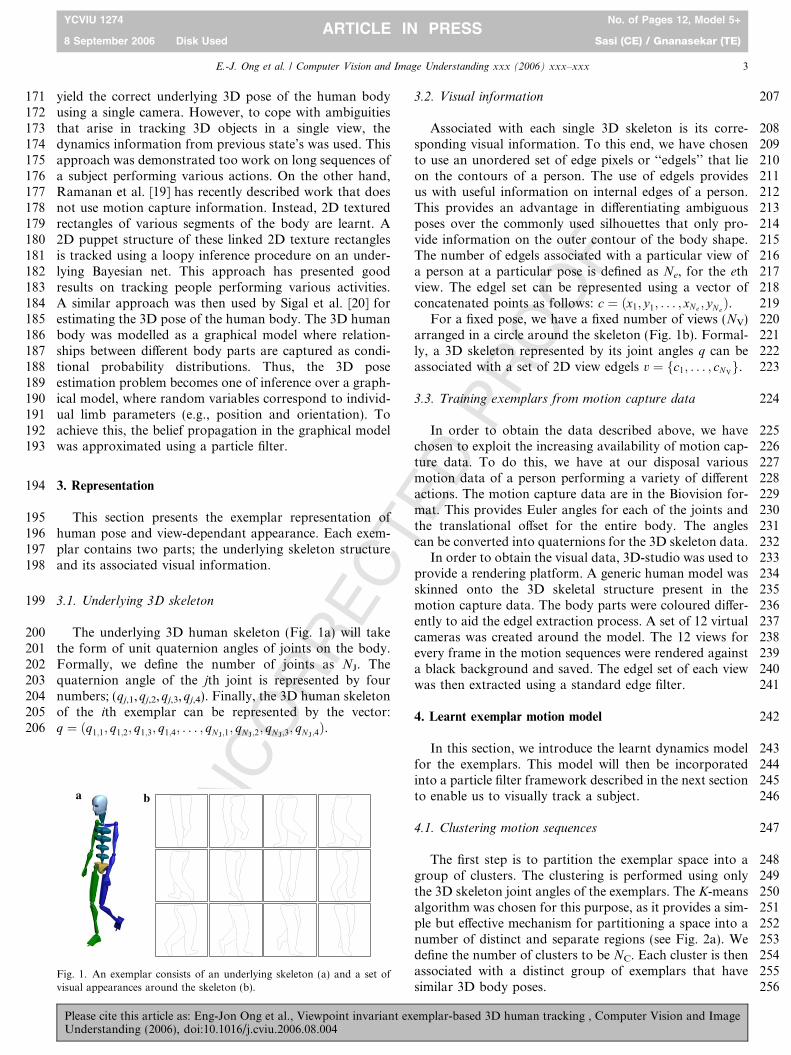
200 The underlying 3D human skeleton (Fig. 1a) will take201 the form of unit quaternion angles of joints on the body.202 Formally, we define the number of joints as NJ. The203 quaternion angle of the jth joint is represented by four204 numbers; (qj,1,qj,2,qj,3,qj,4). Finally, the 3D human skeleton205 of the ith exemplar can be represented by the vector:206 q ¼ ðq1;1; q1;2; q1;3; q1;4; . . . ; qN J;1
; qN J ;2; qN J;3
; qN J;4Þ.
2073.2. Visual information
208Associated with each single 3D skeleton is its corre-209sponding visual information. To this end, we have chosen210to use an unordered set of edge pixels or ‘‘edgels’’ that lie211on the contours of a person. The use of edgels provides212us with useful information on internal edges of a person.213This provides an advantage in differentiating ambiguous214poses over the commonly used silhouettes that only pro-215vide information on the outer contour of the body shape.216The number of edgels associated with a particular view of217a person at a particular pose is defined as Ne, for the eth218view. The edgel set can be represented using a vector of219concatenated points as follows: c ¼ ðx1; y1; . . . ; xNe ; yNe
Þ.220For a fixed pose, we have a fixed number of views (NV)221arranged in a circle around the skeleton (Fig. 1b). Formal-222ly, a 3D skeleton represented by its joint angles q can be223associated with a set of 2D view edgels v ¼ fc1; . . . ; cNV
g.
2243.3. Training exemplars from motion capture data
225In order to obtain the data described above, we have226chosen to exploit the increasing availability of motion cap-227ture data. To do this, we have at our disposal various228motion data of a person performing a variety of different229actions. The motion capture data are in the Biovision for-230mat. This provides Euler angles for each of the joints and231the translational offset for the entire body. The angles232can be converted into quaternions for the 3D skeleton data.233In order to obtain the visual data, 3D-studio was used to234provide a rendering platform. A generic human model was235skinned onto the 3D skeletal structure present in the236motion capture data. The body parts were coloured differ-237ently to aid the edgel extraction process. A set of 12 virtual238cameras was created around the model. The 12 views for239every frame in the motion sequences were rendered against240a black background and saved. The edgel set of each view241was then extracted using a standard edge filter.
2424. Learnt exemplar motion model
243In this section, we introduce the learnt dynamics model244for the exemplars. This model will then be incorporated245into a particle filter framework described in the next section246to enable us to visually track a subject.
2474.1. Clustering motion sequences
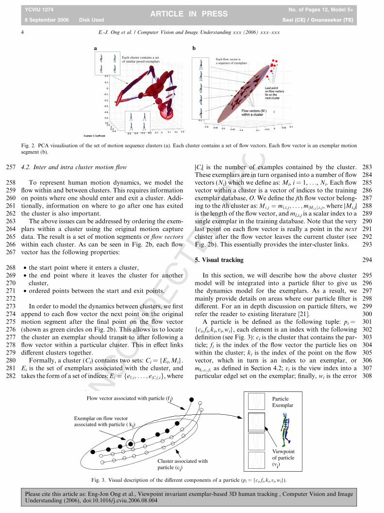
248The first step is to partition the exemplar space into a249group of clusters. The clustering is performed using only250the 3D skeleton joint angles of the exemplars. The K-means251algorithm was chosen for this purpose, as it provides a sim-252ple but effective mechanism for partitioning a space into a253number of distinct and separate regions (see Fig. 2a). We254define the number of clusters to be NC. Each cluster is then255associated with a distinct group of exemplars that have256similar 3D body poses.
a b
Fig. 1. An exemplar consists of an underlying skeleton (a) and a set ofvisual appearances around the skeleton (b).
E.-J. Ong et al. / Computer Vision and Image Understanding xxx (2006) xxx–xxx 3
YCVIU 1274 No. of Pages 12, Model 5+
8 September 2006 Disk Used Sasi (CE) / Gnanasekar (TE)ARTICLE IN PRESS
Please cite this article as: Eng-Jon Ong et al., Viewpoint invariant exemplar-based 3D human tracking , Computer Vision and ImageUnderstanding (2006), doi:10.1016/j.cviu.2006.08.004
UN
CO
RR
EC
TED
PR
OO
F
257 4.2. Inter and intra cluster motion flow
258 To represent human motion dynamics, we model the259 flow within and between clusters. This requires information260 on points where one should enter and exit a cluster. Addi-261 tionally, information on where to go after one has exited262 the cluster is also important.263 The above issues can be addressed by ordering the exem-264 plars within a cluster using the original motion capture265 data. The result is a set of motion segments or flow vectors
266 within each cluster. As can be seen in Fig. 2b, each flow267 vector has the following properties:
268 • the start point where it enters a cluster,269 • the end point where it leaves the cluster for another270 cluster,271 • ordered points between the start and exit points.272273 In order to model the dynamics between clusters, we first274 append to each flow vector the next point on the original275 motion segment after the final point on the flow vector276 (shown as green circles on Fig. 2b). This allows us to locate277 the cluster an exemplar should transit to after following a278 flow vector within a particular cluster. This in effect links279 different clusters together.280 Formally, a cluster (Ci) contains two sets: Ci = {Ei,Mi}.281 Ei is the set of exemplars associated with the cluster, and282 takes the form of a set of indices: Ei ¼ fe1;i; . . . ; ejCi j;ig, where
283|Ci| is the number of examples contained by the cluster.284These exemplars are in turn organised into a number of flow285vectors (Ni) which we define as: Mi, i = 1, . . ., Ni. Each flow286vector within a cluster is a vector of indices to the training287exemplar database, O. We define the jth flow vector belong-288ing to the ith cluster as: Mi;j ¼ ml;i;j; . . . ;mjMi;jj;i;j, where |Mi,j|289is the length of the flow vector, and ml,i,j is a scalar index to a290single exemplar in the training database. Note that the very291last point on each flow vector is really a point in the next
292cluster after the flow vector leaves the current cluster (see293Fig. 2b). This essentially provides the inter-cluster links.
2945. Visual tracking
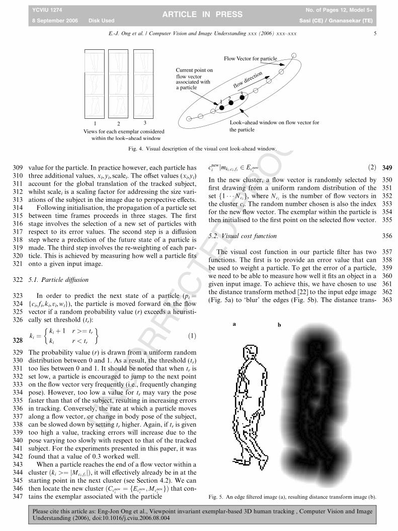
295In this section, we will describe how the above cluster296model will be integrated into a particle filter to give us297the dynamics model for the exemplars. As a result, we298mainly provide details on areas where our particle filter is299different. For an in depth discussion on particle filters, we300refer the reader to existing literature [21].301A particle is be defined as the following tuple: pi =302{ci, fi,ki,vi,wi}, each element is an index with the following303definition (see Fig. 3): ci is the cluster that contains the par-304ticle; fi is the index of the flow vector the particle lies on305within the cluster; ki is the index of the point on the flow306vector, which in turn is an index to an exemplar, or307mki ;ci;fi as defined in Section 4.2; vi is the view index into a308particular edgel set on the exemplar; finally, wi is the error
Each cluster contains a setof similar posed exemplars
Each flow vector isa sequence of exemplars
a b
Fig. 2. PCA visualisation of the set of motion sequence clusters (a). Each cluster contains a set of flow vectors. Each flow vector is an exemplar motionsegment (b).
iCluster associated withparticle (c )
Flow vector associated with particle (f )
i
i
Exemplar on flow vectorassociated with particle ( k )i
ParticleExemplar
Viewpointof particle(v )
Fig. 3. Visual description of the different components of a particle (pi = {ci, fi,ki,vi,wi}).
4 E.-J. Ong et al. / Computer Vision and Image Understanding xxx (2006) xxx–xxx
YCVIU 1274 No. of Pages 12, Model 5+
8 September 2006 Disk Used Sasi (CE) / Gnanasekar (TE)ARTICLE IN PRESS
Please cite this article as: Eng-Jon Ong et al., Viewpoint invariant exemplar-based 3D human tracking , Computer Vision and ImageUnderstanding (2006), doi:10.1016/j.cviu.2006.08.004
UN
CO
RR
EC
TED
PR
OO
F
309 value for the particle. In practice however, each particle has310 three additional values, xi,yi, scalei. The offset values (xi,yi)311 account for the global translation of the tracked subject,312 whilst scalei is a scaling factor for addressing the size vari-313 ations of the subject in the image due to perspective effects.314 Following initialisation, the propagation of a particle set315 between time frames proceeds in three stages. The first316 stage involves the selection of a new set of particles with317 respect to its error values. The second step is a diffusion318 step where a prediction of the future state of a particle is319 made. The third step involves the re-weighting of each par-320 ticle. This is achieved by measuring how well a particle fits321 onto a given input image.
322 5.1. Particle diffusion
323 In order to predict the next state of a particle (pi =324 {ci, fi,ki,vi,wi}), the particle is moved forward on the flow325 vector if a random probability value (r) exceeds a heuristi-326 cally set threshold (tr):
ki ¼ki þ 1 r >¼ tr
ki r < tr
� �ð1Þ
328328
329 The probability value (r) is drawn from a uniform random330 distribution between 0 and 1. As a result, the threshold (tr)331 too lies between 0 and 1. It should be noted that when tr is332 set low, a particle is encouraged to jump to the next point333 on the flow vector very frequently (i.e., frequently changing334 pose). However, too low a value for tr may vary the pose335 faster than that of the subject, resulting in increasing errors336 in tracking. Conversely, the rate at which a particle moves337 along a flow vector, or change in body pose of the subject,338 can be slowed down by setting tr higher. Again, if tr is given339 too high a value, tracking errors will increase due to the340 pose varying too slowly with respect to that of the tracked341 subject. For the experiments presented in this paper, it was342 found that a value of 0.3 worked well.343 When a particle reaches the end of a flow vector within a344 cluster ðki >¼ jMci ;fi jÞ, it will effectively already be in at the345 starting point in the next cluster (see Section 4.2). We can346 then locate the new cluster ðCcnew
i¼ fEcnew
i;Mcnew
igÞ that con-
347 tains the exemplar associated with the particle
cnewi jmki ;ci;fi 2 Ecnew
ið2Þ 349349
350In the new cluster, a flow vector is randomly selected by351first drawing from a uniform random distribution of the352set f1 � � �Ncig, where Nci is the number of flow vectors in353the cluster ci. The random number chosen is also the index354for the new flow vector. The exemplar within the particle is355then initialised to the first point on the selected flow vector.
3565.2. Visual cost function
357The visual cost function in our particle filter has two358functions. The first is to provide an error value that can359be used to weight a particle. To get the error of a particle,360we need to be able to measure how well it fits an object in a361given input image. To achieve this, we have chosen to use362the distance transform method [22] to the input edge image363(Fig. 5a) to ‘blur’ the edges (Fig. 5b). The distance trans-
Flow Vector for particle
the particle
Current point onflow vectorassociated with a particle
noitcerid wolf
1 23
1 32Views for each exemplar considered
Fig. 4. Visual description of the visual cost look-ahead window.
Fig. 5. An edge filtered image (a), resulting distance transform image (b).
E.-J. Ong et al. / Computer Vision and Image Understanding xxx (2006) xxx–xxx 5
YCVIU 1274 No. of Pages 12, Model 5+
8 September 2006 Disk Used Sasi (CE) / Gnanasekar (TE)ARTICLE IN PRESS
Please cite this article as: Eng-Jon Ong et al., Viewpoint invariant exemplar-based 3D human tracking , Computer Vision and ImageUnderstanding (2006), doi:10.1016/j.cviu.2006.08.004
UN
CO
RR
EC
TED
PR
OO
F
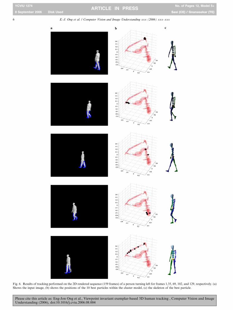
Fig. 6. Results of tracking performed on the 2D rendered sequence (159 frames) of a person turning left for frames 1,35, 69, 102, and 129, respectively. (a)Shows the input image, (b) shows the positions of the 10 best particles within the cluster model, (c) the skeleton of the best particle.
6 E.-J. Ong et al. / Computer Vision and Image Understanding xxx (2006) xxx–xxx
YCVIU 1274 No. of Pages 12, Model 5+
8 September 2006 Disk Used Sasi (CE) / Gnanasekar (TE)ARTICLE IN PRESS
Please cite this article as: Eng-Jon Ong et al., Viewpoint invariant exemplar-based 3D human tracking , Computer Vision and ImageUnderstanding (2006), doi:10.1016/j.cviu.2006.08.004
UN
CO
RR
EC
TED
PR
OO
F
364 form specifies the distance of each pixel to the nearest non-365 zero edge, which are the darker pixels of the distance image366 correspond to the original edges. To calculate the error val-367 ue of a viewpoint associated with a particle, Chamfer368 matching is used [23]. We first translate and scale all the369 corresponding edgels to that of the particle. The error value370 is the mean of the distance transform image pixels that fall371 under the transformed edgels.372 The second step within the visual cost function involves373 a ‘‘look-ahead’’ allowing us to consider poses that are fur-374 ther along a flow vector associated to a particle. This375 allows for variation in speed of the observed motion rela-376 tive to the corresponding exemplars within the learnt377 motion model. Additionally, multiple views are considered378 around the current viewpoint to handle possible turning379 motions. This is achieved by measuring the error of exem-380 plars further down the flow vector that a particle lies on.381 Additionally, for each point on the flow vector considered,382 we look across a window of viewpoints (see Fig. 4). The383 particle viewpoint and on-flow-vector index are both384 updated to the viewpoint on the exemplar with the smallest385 error.
386 6. Experiments
387 This section will provide results for various experiments388 for testing the effectiveness of the proposed tracking model389 in generalising to novel and unseen walking motions. To
390this end, it was found that visual information from the low-391er body was adequate for successful tracking. In the next392section, a description of the training data used for generat-393ing the exemplars is given. A brief discussion on the initiali-394sation methods used for the experiments is then given.395Next, descriptions and results of the test experiments are396given. Each experiment applies the learnt model to image397sequences that contain the following aspects not present398in the training data:
399• Arbitrary walking directions (all experiments): the train-400ing sequences used only contained walking trajectories401down the z-axis. However, all test sequences will contain402walking trajectories in other directions.403• Changing walking trajectories (Experiment 1, Experi-404ment 3): these experiments tests the ability for the model405to generalise from a straight walking trajectories to406various walking trajectories with turns.407• Novel subjects (Experiment 2, Experiment 3): these sets408of experiments also contained tests to see how well the409tracking method can cope with both changes in the visu-410al appearance as well as movement styles of novel test411subjects.412413In order to account for global translations and image414scale variations of the tracked subject, a simple back-415ground subtraction was first performed on each input416image. The mean position and bounding box of the
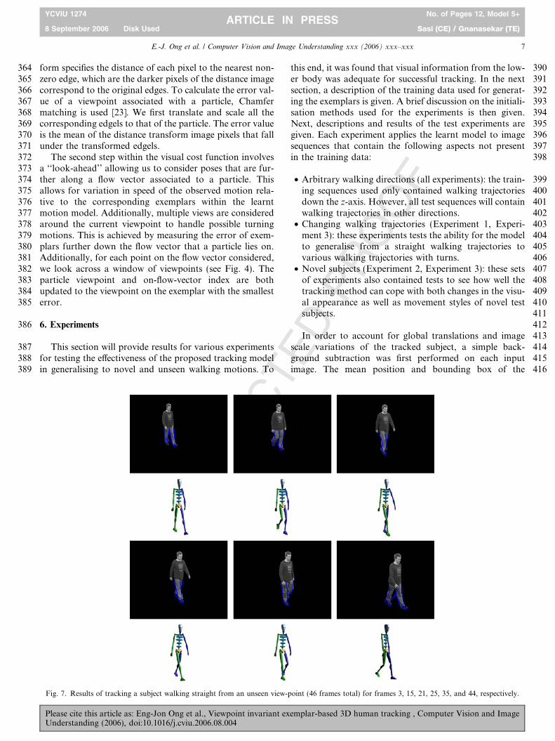
Fig. 7. Results of tracking a subject walking straight from an unseen view-point (46 frames total) for frames 3, 15, 21, 25, 35, and 44, respectively.
E.-J. Ong et al. / Computer Vision and Image Understanding xxx (2006) xxx–xxx 7
YCVIU 1274 No. of Pages 12, Model 5+
8 September 2006 Disk Used Sasi (CE) / Gnanasekar (TE)ARTICLE IN PRESS
Please cite this article as: Eng-Jon Ong et al., Viewpoint invariant exemplar-based 3D human tracking , Computer Vision and ImageUnderstanding (2006), doi:10.1016/j.cviu.2006.08.004
UN
CO
RR
EC
TED
PR
OO
F
417 foreground pixels was then obtained. The mean position418 with added Gaussian white noise was then used to set each419 particle’s offset values. Additionally, the scale factor of420 each particle was obtained by first estimating the variance421 of the y values of foreground pixels. A ratio between half422 the variance (with added Gaussian noise) and the bounding423 box height of the particles visual examples provides the424 estimated scaling factor.
425 6.1. Exemplars training data
426 To learn the motion model, a database that consisted of427 motion capture data (29 joint angles for the whole body) of428 a single subject only walking in a straight line ahead was429 used (down the z-axis). The total number of frames used430 was 734. Every frame in the training sequence was used,431 to generate exemplars as described in Section 3.3. It was432 found that the storage requirement for all 734 exemplars433 was small and totalled approximately 13 Mb of memory.434 Following this, an exemplar motion model was built as435 described in Section 4. The number of clusters in the436 motion model was set empirically to 30.
437 6.2. Tracking particles initialisation
438 For all the experiments presented in this paper, the ini-439 tialisation for tracking was done in a semi-supervised man-440 ner. The user first specifies a small set of exemplars, usually
441from a short training motion sequence (e.g. quarter cycle in442a walking sequence). Given the input image’s distance443transform image, an exhaustive match is performed over444all viewpoints and poses from this set of exemplars. This445will provide a simultaneous estimation for the initial pose446and viewpoint for the particles in the tracking system. This447method was found to be more accurate and effective at448locating the correct starting pose and viewpoint than a fully449automated initialisation process involving an exhaustive450search over all the viewpoints of every exemplar. It was451found that such an exhaustive search was more susceptible452to matching to wrong poses or viewpoints due to ambigu-453ities in the visual information used. When tracking is per-454formed, it was found that 200 particles were sufficient to455successfully track the subject in all test sequences.
4566.3. Experiment 1: simulated data, turning walk
457The first experiment shows the tracking of a rendered4582D video sequence of the generic 3D model walking from459an unseen angle. Additionally, the model is made to turn46090� at the middle of the sequence. It is important to note461that although the 3D model used is similar to that for gen-462erating the training data, its underlying motion is com-463pletely unseen with novel movement dynamics. The464results can be seen in Fig. 6. The first column (leftmost)465shows the input image along with the best 2D edgels over-466laid. The second column shows the 5 best particles in the
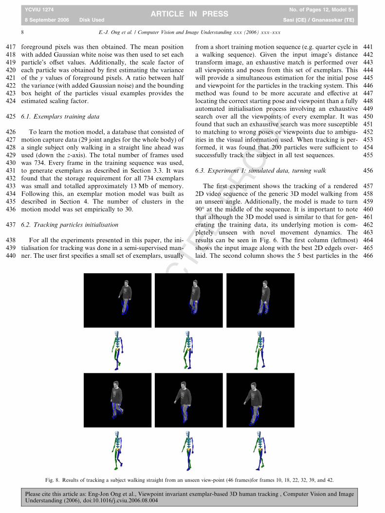
Fig. 8. Results of tracking a subject walking straight from an unseen view-point (46 frames)for frames 10, 18, 22, 32, 39, and 42.
8 E.-J. Ong et al. / Computer Vision and Image Understanding xxx (2006) xxx–xxx
YCVIU 1274 No. of Pages 12, Model 5+
8 September 2006 Disk Used Sasi (CE) / Gnanasekar (TE)ARTICLE IN PRESS
Please cite this article as: Eng-Jon Ong et al., Viewpoint invariant exemplar-based 3D human tracking , Computer Vision and ImageUnderstanding (2006), doi:10.1016/j.cviu.2006.08.004
UN
CO
RR
EC
TED
PR
OO
F
467 cluster visualisation model. This allows us to see how the468 particles traverse across the different clusters during the469 tracking process. The third column shows the 3D skeleton470 rendered from the best viewpoint associated with the best471 particle. It should be noted that only the lower body (i.e.,472 legs) is tracked. However, the 3D skeleton shown has cor-473 rect upper body movements as well. The reason for this is474 because the 3D information in each exemplar is for the475 entire body. Thus, although only the legs are tracked, we476 have the corresponding 3D information for both the upper477 and lower body.
478 6.4. Experiment 2: novel video data, straight walk
479 The purpose of the next experiments is to test the ability480 for the method to cope not only with unseen motion481 dynamics (style, speed, and length), but also unseen visual482 information. The subject used in these video sequences has483 nothing to do with the motion capture information used in484 training. The second experiment tests the ability of our485 method for handling real video sequences of a subject486 walking in a straight motion.
487Two sequences of a subject walking in a straight line488were captured from two novel viewpoints in a studio envi-489ronment. Background subtraction and chroma threshold-490ing was then performed on the sequences to extract the491foreground object. Tracking was then performed using492the particle filter with an equivalent of 200 particles. The493results can be seen in Figs. 7 and 8 for each viewpoint494respectively. It can be seen that the tracker is successful495in determining the correct viewpoint as well as the 3D pose496of the subject.
4976.5. Experiment 3: novel video data, turning walk
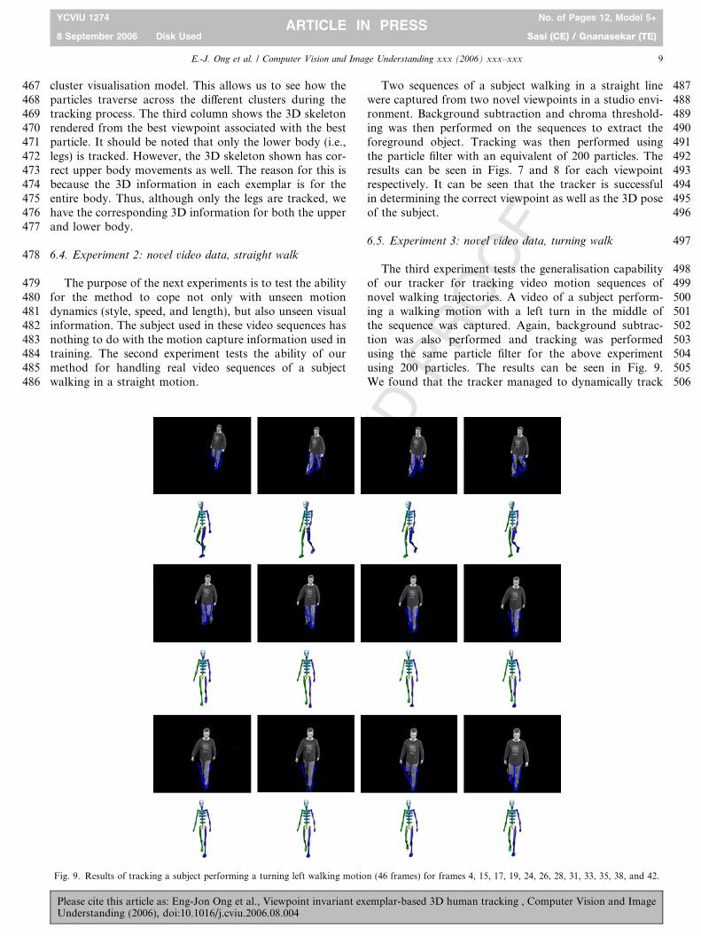
498The third experiment tests the generalisation capability499of our tracker for tracking video motion sequences of500novel walking trajectories. A video of a subject perform-501ing a walking motion with a left turn in the middle of502the sequence was captured. Again, background subtrac-503tion was also performed and tracking was performed504using the same particle filter for the above experiment505using 200 particles. The results can be seen in Fig. 9.506We found that the tracker managed to dynamically track
Fig. 9. Results of tracking a subject performing a turning left walking motion (46 frames) for frames 4, 15, 17, 19, 24, 26, 28, 31, 33, 35, 38, and 42.
E.-J. Ong et al. / Computer Vision and Image Understanding xxx (2006) xxx–xxx 9
YCVIU 1274 No. of Pages 12, Model 5+
8 September 2006 Disk Used Sasi (CE) / Gnanasekar (TE)ARTICLE IN PRESS
Please cite this article as: Eng-Jon Ong et al., Viewpoint invariant exemplar-based 3D human tracking , Computer Vision and ImageUnderstanding (2006), doi:10.1016/j.cviu.2006.08.004
UN
CO
RR
EC
TED
PR
OO
F
507 the changes in 3D pose and viewpoints as the subject508 performed the motion. However, we note that the track-509 ing from the frontal view is rather ambiguous and is510 sometimes difficult to determine the exact pose of the511 subject.
512 6.6. Performance
513 This section provides a more detailed analysis on the514 results of the experiments discussed in the previous section.515 In order to do this, ground truth data in the form of foot516 positions were first obtained. This was achieved by manu-517 ally labelling the positions of the centre of the feet for every518 frame of every test sequence. However, it is noted that519 because feet can often get occluded from different angles,520 some amount of guesswork had to be carried out in order521 to label feet that could not be seen.522 Additionally, for the purpose of error analysis, the foot523 positions for each exemplar were also calculated. This was524 achieved by separately identifying vertices belonging to the525 left and right foot on the original 3D model. To obtain the526 mean position of the foot (left or right), only polygons527 associated with the required foot were given a colour. All528 other polygons (including the other foot) were assigned a529 transparent material. The images were rendered from530 exactly the same virtual cameras used for obtaining the531 edgel information. Having obtained the image where the532 only object present is the foot, simple image processing533 can be used to extract the mean of the 2D foot position534 for a particular view and pose.
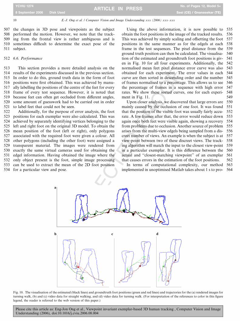
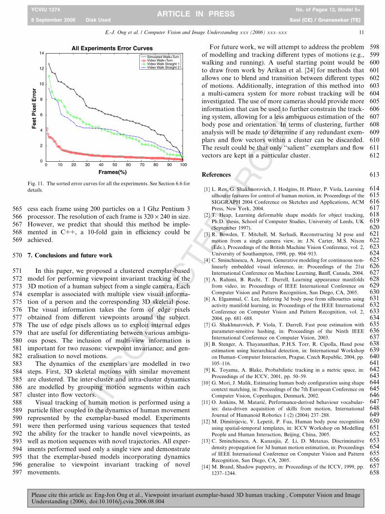
535Using the above information, it is now possible to536obtain the foot positions in the image of the tracked results.537This was achieved by simply scaling and offsetting the foot538positions in the same manner as for the edgels at each539frame in the test sequences. The pixel distance from the540ground truth position can then be calculated. The visualisa-541tion of the estimated and groundtruth foot positions is giv-542en in Fig. 10 for all four experiments. Additionally, the543normalised mean feet pixel distance error curve was also544obtained for each experiment. The error values in each545curve are then sorted in descending order and the number546of frames normalised to a percentage. This allows us to see547the percentage of frames in a sequence with high error548rates. We show these sorted curves, one for each experi-549ment in Fig. 11.550Upon closer analysis, we discovered that large errors are551mainly caused by the occlusion of one foot. It was found552that the position of the visible foot was usually fairly accu-553rate. A few frames after that, the error would reduce down554again once both feet were visible again, showing a recovery555from problems due to occlusion. Another source of problem556arises from the multi-view edgels being sampled from a dis-557creet number of views. An example is when the subject is at558view-point between two of these discreet views. The track-559ing algorithm will match the input to the closest view-point560in a particular exemplar. It is this difference between the561actual and ‘‘closest-matching viewpoint’’ of an exemplar562that causes errors in the estimation of the foot positions.563In terms of computational complexity, our method564implemented in unoptimised Matlab takes about 1 s to pro-
a
b c d
Fig. 10. The visualisation of the estimated (black lines) and groundtruth foot positions (green and red lines) and trajectories for the (a) rendered images forturning walk, (b) and (c) video data for straight walking, and (d) video data for turning walk. (For interpretation of the references to color in this figurelegend, the reader is referred to the web version of this paper.)
10 E.-J. Ong et al. / Computer Vision and Image Understanding xxx (2006) xxx–xxx
YCVIU 1274 No. of Pages 12, Model 5+
8 September 2006 Disk Used Sasi (CE) / Gnanasekar (TE)ARTICLE IN PRESS
Please cite this article as: Eng-Jon Ong et al., Viewpoint invariant exemplar-based 3D human tracking , Computer Vision and ImageUnderstanding (2006), doi:10.1016/j.cviu.2006.08.004
UN
CO
RR
EC
TED
PR
OO
F
565 cess each frame using 200 particles on a 1 Ghz Pentium 3566 processor. The resolution of each frame is 320 · 240 in size.567 However, we predict that should this method be imple-568 mented in C++, a 10-fold gain in efficiency could be569 achieved.
570 7. Conclusions and future work
571 In this paper, we proposed a clustered exemplar-based572 model for performing viewpoint invariant tracking of the573 3D motion of a human subject from a single camera. Each574 exemplar is associated with multiple view visual informa-575 tion of a person and the corresponding 3D skeletal pose.576 The visual information takes the form of edge pixels577 obtained from different viewpoints around the subject.578 The use of edge pixels allows us to exploit internal edges579 that are useful for differentiating between various ambigu-580 ous poses. The inclusion of multi-view information is581 important for two reasons: viewpoint invariance; and gen-582 eralisation to novel motions.583 The dynamics of the exemplars are modelled in two584 steps. First, 3D skeletal motions with similar movement585 are clustered. The inter-cluster and intra-cluster dynamics586 are modelled by grouping motion segments within each587 cluster into flow vectors.588 Visual tracking of human motion is performed using a589 particle filter coupled to the dynamics of human movement590 represented by the exemplar-based model. Experiments591 were then performed using various sequences that tested592 the ability for the tracker to handle novel viewpoints, as593 well as motion sequences with novel trajectories. All exper-594 iments performed used only a single view and demonstrate595 that the exemplar-based models incorporating dynamics596 generalise to viewpoint invariant tracking of novel597 movements.
598For future work, we will attempt to address the problem599of modelling and tracking different types of motions (e.g.,600walking and running). A useful starting point would be601to draw from work by Arikan et al. [24] for methods that602allows one to blend and transition between different types603of motions. Additionally, integration of this method into604a multi-camera system for more robust tracking will be605investigated. The use of more cameras should provide more606information that can be used to further constrain the track-607ing system, allowing for a less ambiguous estimation of the608body pose and orientation. In terms of clustering, further609analysis will be made to determine if any redundant exem-610plars and flow vectors within a cluster can be discarded.611The result could be that only ‘‘salient’’ exemplars and flow612vectors are kept in a particular cluster.
613References
614[1] L. Ren, G. Shakhnorovich, J. Hodgins, H. Pfister, P. Viola, Learning615silhoutte features for control of human motion, in: Proceedings of the616SIGGRAPH 2004 Conference on Sketches and Applications, ACM617Press, New York, 2004.618[2] T. Heap, Learning deformable shape models for object tracking,619Ph.D. thesis, School of Computer Studies, University of Leeds, UK620(September 1997).621[3] R. Bowden, T. Mitchell, M. Sarhadi, Reconstructing 3d pose and622motion from a single camera view, in: J.N. Carter, M.S. Nixon623(Eds.), Proceedings of the British Machine Vision Conference, vol. 2,624University of Southampton, 1998, pp. 904–913.625[4] C. Sminchisescu, A. Jepson, Generative modeling for continuous non-626linearly embedded visual inference, in: Proceedings of the 21st627International Conference on Machine Learning, Banff, Canada, 2004.628[5] A. Rahimi, B. Recht, T. Darrell, Learning appearance manifolds629from video, in: Proceedings of IEEE International Conference on630Computer Vision and Pattern Recognition, San Diego, CA, 2005.631[6] A. Elgammal, C. Lee, Inferring 3d body pose from silhouettes using632activity manifold learning, in: Proceedings of the IEEE International633Conference on Computer Vision and Pattern Recognition, vol. 2,6342004, pp. 681–688.635[7] G. Shakhnarovich, P. Viola, T. Darrell, Fast pose estimation with636parameter-sensitive hashing, in: Proceedings of the Ninth IEEE637International Conference on Computer Vision, 2003.638[8] B. Stenger, A. Thayananthan, P.H.S. Torr, R. Cipolla, Hand pose639estimation using hierarchical detection, in: International Workshop640on Human–Computer Interaction, Prague, Czech Republic, 2004, pp.641105–116.642[9] K. Toyama, A. Blake, Probabilistic tracking in a metric space, in:643Proceedings of the ICCV, 2001, pp. 50–59.644[10] G. Mori, J. Malik, Estimating human body configuration using shape645context matching, in: Proceedings of the 7th European Conference on646Computer Vision, Copenhagen, Denmark, 2002.647[11] O. Jenkins, M. Mataric, Performance-derived behaviour vocabular-648ies: data-driven acquisition of skills from motion, International649Journal of Humanoid Robotics 1 (2) (2004) 237–288.650[12] M. Dimitrijevic, V. Lepetit, P. Fua, Human body pose recognition651using spatial-temporal templates, in: ICCV Workshop on Modelling652People and Human Interaction, Beijing, China, 2005.653[13] C. Sminchisescu, A. Kanaujia, Z. Li, D. Metaxas, Discriminative654density propagation for 3d human motion estimation, in: Proceedings655of IEEE International Conference on Computer Vision and Pattern656Recognition, San Diego, CA, 2005.657[14] M. Brand, Shadow puppetry, in: Proceedings of the ICCV, 1999, pp.6581237–1244.
0 10 20 30 40 50 60 70 80 90 1000
2
4
6
8
10
12
14
Frames(%)
Fee
t P
ixel
Err
or
All Experiments Error CurvesSimulated Walk+TurnVideo Walk+TurnVideo Walk Straight 1Video Walk Straight 2
Fig. 11. The sorted error curves for all the experiments. See Section 6.6 fordetails.
E.-J. Ong et al. / Computer Vision and Image Understanding xxx (2006) xxx–xxx 11
YCVIU 1274 No. of Pages 12, Model 5+
8 September 2006 Disk Used Sasi (CE) / Gnanasekar (TE)ARTICLE IN PRESS
Please cite this article as: Eng-Jon Ong et al., Viewpoint invariant exemplar-based 3D human tracking , Computer Vision and ImageUnderstanding (2006), doi:10.1016/j.cviu.2006.08.004

UN
CO
RR
EC
TED
PR
OO
F
659 [15] H. Sidenbladh, M.J. Black, L. Sigal, Implicit probabilistic models of660 human motion for synthesis and tracking, in: Proceedings of the661 ECCV (1), 2002, pp. 784–800.662 [16] N. Howe, M. Leventon, W. Freeman, Bayesian reconstructions of 3d663 human motion from single camera video, in: NIPS, 1999.664 [17] R. Urtasun, P. Fua, 3d human body tracking using deterministic665 motion models, in: Proceedings of the ECCV, 2004.666 [18] A. Agarwal, B. Triggs, Recovering 3d human pose from monocular667 images, IEEE Transactions on Pattern Analysis and Machine668 Intelligence 28 (1) (2006) 44–58.669 [19] D. Ramanan, D. Forsyth, Finding and tracking people from the670 bottom up, in: Proceedings of IEEE International Conference on671 Computer Vision and Pattern Recognition, 2003.672 [20] L. Sigal, M. Isard, B. Sigelman, M. Black, Attractive people:673 assembling loose-limbed models using non-parametric belief propa-
674gation, in: Advances in Neural Information Processing, 2003, pp.6751539–1546.676[21] M. Isard, A. Blake, Condensation—conditional density propagation677for visual tracking, International Journal of Computer Vision 29 (1)678(1998) 5–28.679[22] P. Felzenszwalb, D. Hurrenlocher, Distance transforms of sampled680functions, Technical Report TR2004-1963, Cornell Computing and681Information Science (2004).682[23] H. Barrow, J. Tenenbaum, R. Bolles, H. Wolf, Parametric corre-683spondence and chamfer matching: two new techniques for image684matching, in: Proceedings of Joint Conference on Artificial Intelli-685gence, 1977, pp. 659–663.686[24] O. Arikan, D. Forsyth, Interactive motion generation from687examples, ACM Transactions on Graphics 21 (2002) 483–688490.
689
12 E.-J. Ong et al. / Computer Vision and Image Understanding xxx (2006) xxx–xxx
YCVIU 1274 No. of Pages 12, Model 5+
8 September 2006 Disk Used Sasi (CE) / Gnanasekar (TE)ARTICLE IN PRESS
Please cite this article as: Eng-Jon Ong et al., Viewpoint invariant exemplar-based 3D human tracking , Computer Vision and ImageUnderstanding (2006), doi:10.1016/j.cviu.2006.08.004