view universal 1 series pump product brochure - spx · pdf filethe waukesha cherry-burrell...
TRANSCRIPT
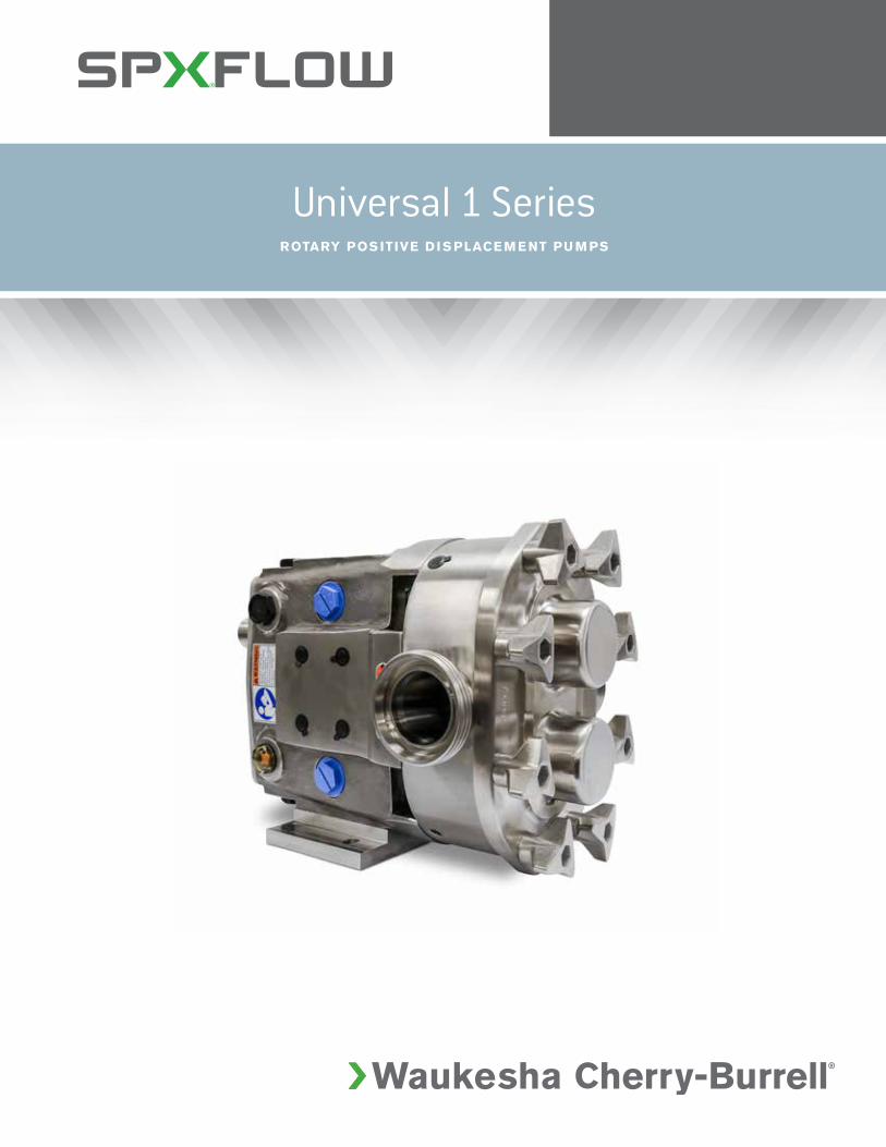
Universal 1 SeriesROTARY POS ITIVE D I S PLACE M E NT PU M PS
SPX FLOW, Inc. (NYSE:FLOW) is a leading
manufacturer of innovative flow technologies,
many of which help define the industry standard
in the market segments they serve. From its
headquarters in Charlotte, North Carolina, it
operates a sales and support network, centers
of manufacturing excellence, and advanced
engineering facilities, throughout the world. Its
cutting-edge flow components and process
equipment portfolio includes a wide range
of pumps, valves, heat exchangers, mixers,
homogenizers, separators, filters, UHT, and drying
technology that meet many application needs.
Its expert engineering capability also makes it a
premium supplier of customized solutions and
complete, turn-key packages to meet the most
exacting of installation demands.
Incorporating many leading brands, SPX FLOW
has a long history of serving the food and
beverage, power and energy, and industrial market
sectors. Its designs and engineered solutions
help customers drive efficiency and productivity,
increase quality and reliability, and meet the latest
regulatory demands. In-depth understanding
of applications and processes, state-of-the-art
Innovation Centers, and advanced pilot/testing
technology further assist in optimizing processes
and reducing timescales to reliably meet
production targets.
To learn more about SPX FLOW capabilities,
its latest technology innovations and complete
service offerings, please visit www.spxflow.com.
2
PROD UCT FEATU R E S AN D B E N E FITS
Sanitation features
• 316L stainless steel body, cover, and shaft
• Easy disassembly for COP cleaning
• Elastomers that comply with FDA requirements
• Aseptic models available
• Meets 3-A sanitary standards
Long-life features
• Up to 200 psi (13.8 bar) pressure capability*
• No bearings in product zone
• Heavy duty bearing frame with large diameter shafts
• Grease lubed bearings for positive lubrication of all bearing over entire speed,
temperature and pressure range
• Non-galling Waukesha “88” alloy rotors standard; permits running at tighter
clearances and pumping a wide range of viscosities
• Remanufacturing and Inspect and Advise programs to extend life and reduce costs
Available options
* High strength 17-4 PH shafts and hex cover nuts for higher pressure applications
• Stainless steel gear case
• Stainless steel bearing retainers
• Bearing isolators protect bearings from contamination
• Body retaining screws
• Steel-It paint
• Single wing rotors for minimum damage of particulates.
• Jacketed or vented covers
• Rectangular flange inlet for high viscosity products
• Tru-Fit® close coupled pump design
For more than half a century, Waukesha
Cherry-Burrell has been a leader in the design,
manufacturing and application of external
circumferential piston (ECP) style, rotary positive
displacement pumps. Waukesha Cherry-Burrell
PD pumps are in service around the world
in food, dairy, canning, bakery, beverage and
pharmaceutical processing, as well as difficult
chemical and industrial applications.
Users of Waukesha Cherry-Burrell PD
pumps benefit from decades of continuing
product improvement. Steady advances in
design, metallurgy and fabrication techniques
have yielded progressively higher levels of
performance and service life.
Setting the standard of performance for the
sanitary industry for over 50 years.
3
Installation Features
• Bidirectional flow. Rotors, locked with double jam nuts, rotate
securely in either direction.
• No flow direction/shaft position specifications
• Versatile 3-Way mounting of gear case, including vertical alignment
of ports
• Upper or lower shaft position
• Easy to install or convert single O-ring to mechanical seals
• Interchangeable installation dimensions with Universal 2 and
Universal Lobe PD pumps
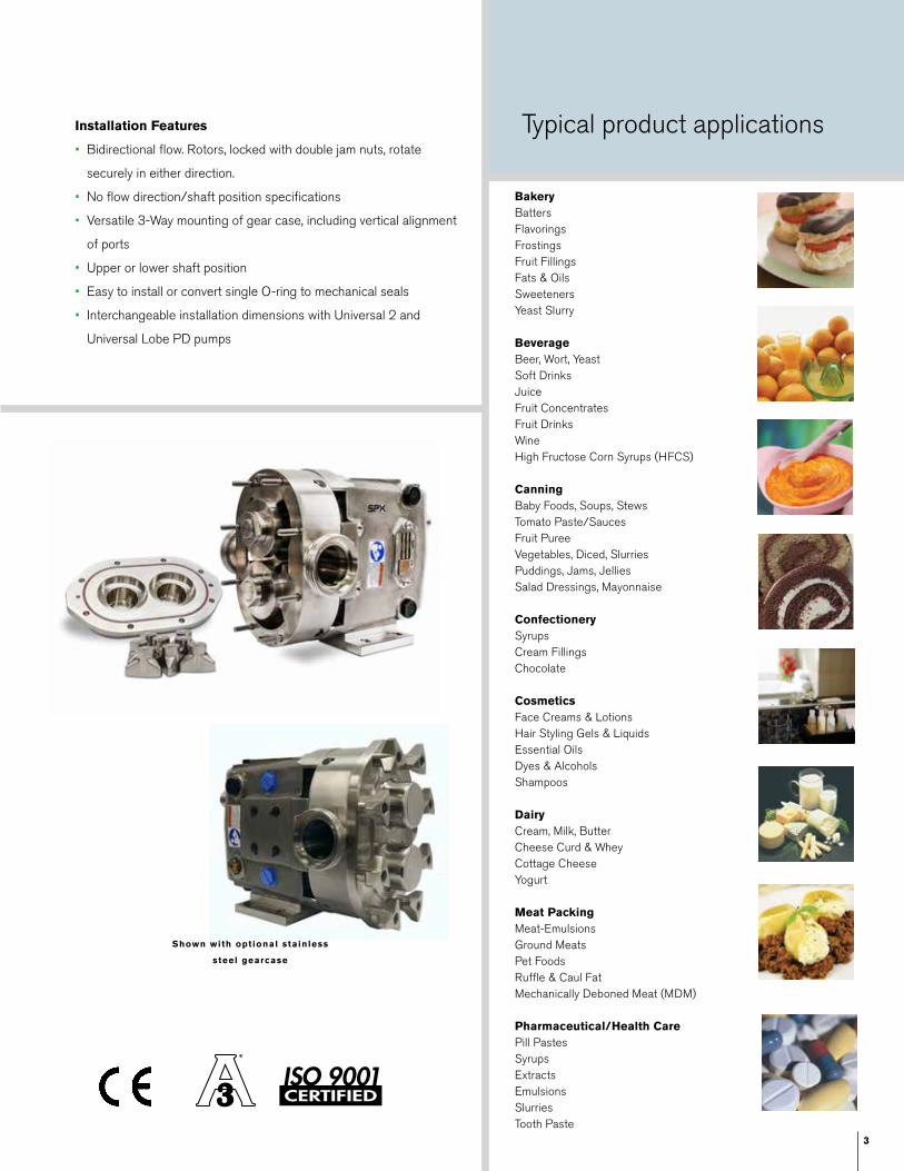
Shown with optional stainless
steel gearcase
BakeryBattersFlavoringsFrostingsFruit FillingsFats & OilsSweetenersYeast Slurry
BeverageBeer, Wort, YeastSoft DrinksJuiceFruit ConcentratesFruit DrinksWineHigh Fructose Corn Syrups (HFCS)
CanningBaby Foods, Soups, Stews Tomato Paste/SaucesFruit PureeVegetables, Diced, Slurries Puddings, Jams, Jellies Salad Dressings, Mayonnaise
ConfectionerySyrupsCream FillingsChocolate
CosmeticsFace Creams & LotionsHair Styling Gels & LiquidsEssential OilsDyes & AlcoholsShampoos
DairyCream, Milk, ButterCheese Curd & WheyCottage CheeseYogurt
Meat PackingMeat-EmulsionsGround MeatsPet FoodsRuffle & Caul FatMechanically Deboned Meat (MDM)
Pharmaceutical/Health CarePill PastesSyrupsExtractsEmulsionsSlurriesTooth Paste
Typical product applications
4
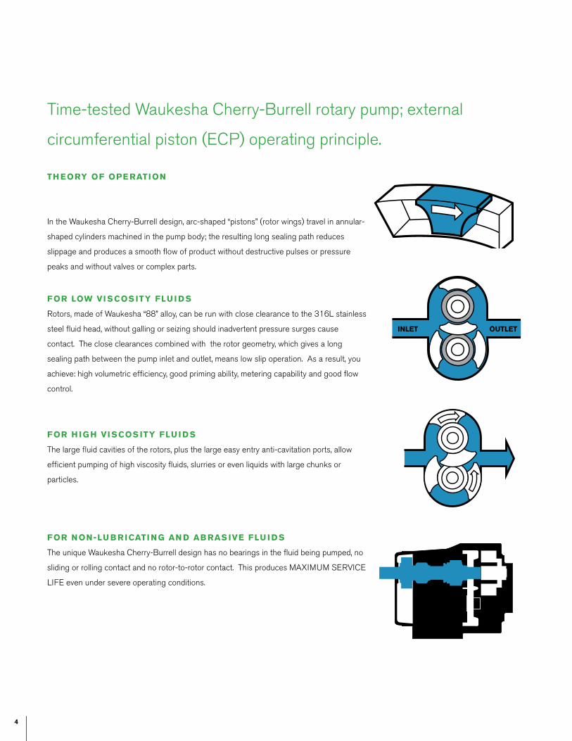
TH EORY OF OPE RATION
In the Waukesha Cherry-Burrell design, arc-shaped “pistons” (rotor wings) travel in annular-
shaped cylinders machined in the pump body; the resulting long sealing path reduces
slippage and produces a smooth flow of product without destructive pulses or pressure
peaks and without valves or complex parts.
FOR LOW VI SCOS ITY FLU I D S
Rotors, made of Waukesha “88” alloy, can be run with close clearance to the 316L stainless
steel fluid head, without galling or seizing should inadvertent pressure surges cause
contact. The close clearances combined with the rotor geometry, which gives a long
sealing path between the pump inlet and outlet, means low slip operation. As a result, you
achieve: high volumetric efficiency, good priming ability, metering capability and good flow
control.
FOR H IG H VI SCOS ITY FLU I D S
The large fluid cavities of the rotors, plus the large easy entry anti-cavitation ports, allow
efficient pumping of high viscosity fluids, slurries or even liquids with large chunks or
particles.
FOR NON-LU B R ICATI NG AN D AB RAS IVE FLU I D S
The unique Waukesha Cherry-Burrell design has no bearings in the fluid being pumped, no
sliding or rolling contact and no rotor-to-rotor contact. This produces MAXIMUM SERVICE
LIFE even under severe operating conditions.
Time-tested Waukesha Cherry-Burrell rotary pump; external
circumferential piston (ECP) operating principle.
INLET OUTLET
5
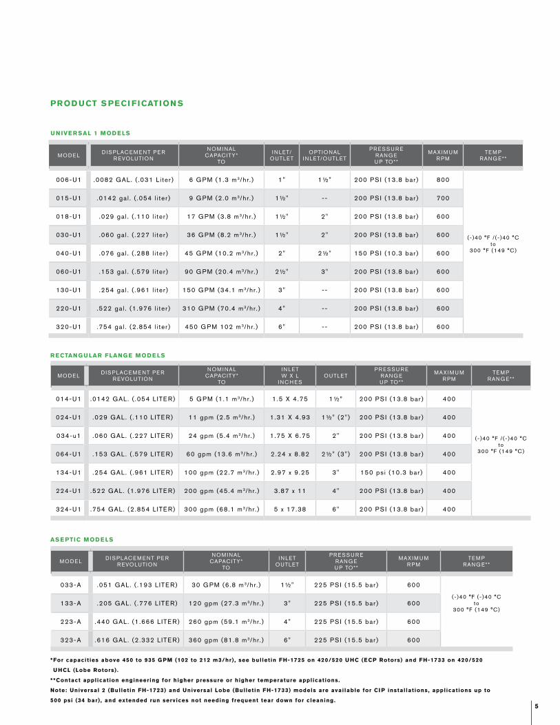
PROD UCT S PECI FICATION S
U N IVE R SAL 1 MOD E LS
* For capacit ies above 450 to 935 G PM (102 to 212 m3/hr) , see bul let in FH-1725 on 420/520 U HC (ECP Rotors) and FH-1733 on 420/520
U HCL (Lobe Rotors) .
**Contact appl icat ion engineering for higher pressure or higher temperature appl icat ions.
Note: Universal 2 (Bul let in FH-1723) and Universal Lobe (Bul let in FH-1733) models are avai lable for CI P instal lat ions, appl icat ions up to
500 psi (34 bar) , and extended run services not needing frequent tear down for cleaning.
AS E PTIC MOD E LS
MODE L DISPLACE M E NT PE R R EVOLUTION
NOM I NAL CAPACITY*
TO
I N LET/OUTLET
OPTIONALI N LET/OUTLET
PR ESSU R ERANG EU P TO**
MAX I M U MR PM
TE M PRANG E**
006-U1 .0082 GAL. ( .031 L i te r ) 6 G PM (1 .3 m 3/hr. ) 1" 1½" 200 PS I (13.8 bar ) 800
(-)40 °F / ( - )40 °Cto
300 °F (149 °C)
015-U1 .0142 ga l . ( .054 l i te r ) 9 G PM (2 .0 m 3/hr. ) 1½" -- 200 PS I (13.8 bar ) 700
018-U1 .029 ga l . ( .110 l i te r ) 17 G PM (3 .8 m 3/hr. ) 1½" 2" 200 PS I (13.8 bar ) 600
030-U1 .060 ga l . ( .227 l i te r ) 36 G PM (8 .2 m 3/hr. ) 1½" 2" 200 PS I (13.8 bar ) 600
040-U1 .076 ga l . ( .288 l i te r ) 45 G PM (10.2 m 3/hr. ) 2" 2½" 150 PS I (10.3 bar ) 600
060-U1 .153 ga l . ( .579 l i te r ) 90 G PM (20.4 m 3/hr. ) 2½" 3" 200 PS I (13.8 bar ) 600
130-U1 .254 ga l . ( .961 l i te r ) 150 G PM (34.1 m 3/hr. ) 3" -- 200 PS I (13.8 bar ) 600
220-U1 .522 ga l . (1 .976 l i te r ) 310 G PM (70.4 m 3/hr. ) 4" -- 200 PS I (13.8 bar ) 600
320-U1 .754 ga l . (2 .854 l i te r ) 450 G PM 102 m 3/hr. ) 6" -- 200 PS I (13.8 bar ) 600
R ECTANG U LAR FLANG E MOD E LS
MODE L DISPLACE M E NT PE R R EVOLUTION
NOM I NAL CAPACITY*
TO
I N LETW X L
I NCH ESOUTLET
PR ESSU R ERANG EU P TO**
MAX I M U MR PM
TE M PRANG E**
014-U1 .0142 GAL. ( .054 L ITE R) 5 G PM (1 .1 m 3/hr. ) 1 .5 X 4 .75 1½” 200 PS I (13.8 bar ) 400
(-)40 °F / ( - )40 °Cto
300 °F (149 °C)
024-U1 .029 GAL. ( .110 L ITE R) 11 gpm (2 .5 m 3/hr. ) 1 .31 X 4 .93 1½" (2" ) 200 PS I (13.8 bar ) 400
034-u1 .060 GAL. ( .227 L ITE R) 24 gpm (5 .4 m 3/hr. ) 1 .75 X 6 .75 2" 200 PS I (13.8 bar ) 400
064-U1 .153 GAL. ( .579 L ITE R) 60 gpm (13.6 m 3/hr. ) 2 .24 x 8 .82 2½" (3" ) 200 PS I (13.8 bar ) 400
134-U1 .254 GAL. ( .961 L ITE R) 100 gpm (22.7 m 3/hr. ) 2 .97 x 9 .25 3" 150 ps i (10.3 bar ) 400
224-U1 .522 GAL. (1 .976 L ITE R) 200 gpm (45.4 m 3/hr. ) 3 .87 x 11 4" 200 PS I (13.8 bar ) 400
324-U1 .754 GAL. (2 .854 L ITE R) 300 gpm (68.1 m 3/hr. ) 5 x 17.38 6" 200 PS I (13.8 bar ) 400
MODE L DISPLACE M E NT PE R R EVOLUTION
NOM I NAL CAPACITY*
TO
I N LETOUTLET
PR ESSU R ERANG EU P TO**
MAX I M U MR PM
TE M PRANG E**
033-A .051 GAL. ( .193 L ITE R) 30 G PM (6 .8 m 3/hr. ) 1½" 225 PS I (15.5 bar ) 600
(-)40 °F ( - )40 °Cto
300 °F (149 °C)133-A .205 GAL. ( .776 L ITE R) 120 gpm (27.3 m 3/hr. ) 3" 225 PS I (15.5 bar ) 600
223-A .440 GAL. (1 .666 L ITE R) 260 gpm (59.1 m 3/hr. ) 4" 225 PS I (15.5 bar ) 600
323-A .616 GAL. (2 .332 L ITE R) 360 gpm (81.8 m 3/hr. ) 6" 225 PS I (15.5 bar ) 600
6
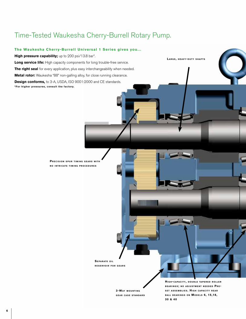
High pressure capability; up to 200 psi/13.8 bar*.
Long service life: High capacity components for long trouble-free service.
The right seal for every application, plus easy interchangeability when needed.
Metal rotor: Waukesha “88” non-galling alloy, for close running clearance.
Design conforms, to 3-A, USDA, ISO 9001:2000 and CE standards. *For higher pressures, consult the factory.
Time-Tested Waukesha Cherry-Burrell Rotary Pump.
Se pa r at e o i l
r e S e r vo i r f o r g e a r S
Hi g H-ca pac i t y , d o u b l e ta p e r e d r o l l e r
b e a r i n g S; n o a dj u S t m e n t n e e d e d pr e-
S e t a S S e m b l i e S . Hi g H ca pac i t y r e a r
ba l l b e a r i n g S o n mo d e l S 6 , 15,18,
30 & 40
la r g e, H e av y-d u t y S H a f t S
pr e c i S i o n S p u r t i m i n g g e a r S w i t H
n o i n t r i cat e t i m i n g p r o c e d u r e S
3-way m o u n t i n g
g e a r ca S e S ta n da r d
The Waukesha Cherry-Burrel l Universal 1 Series gives you. . .
7
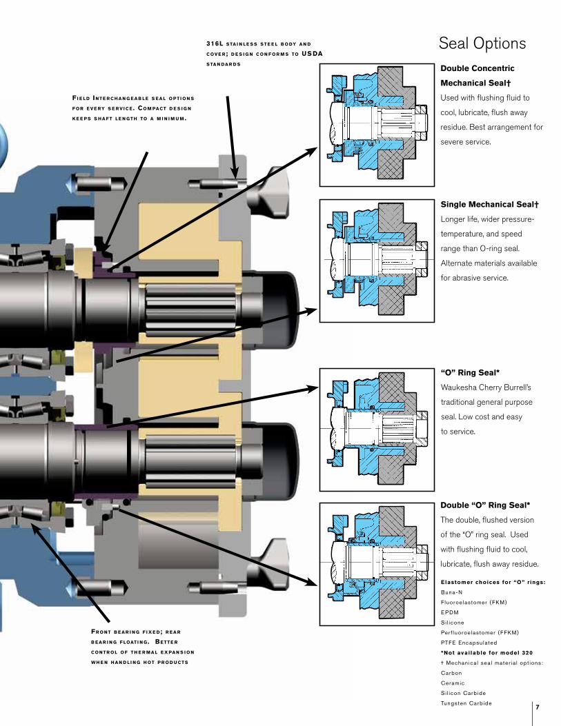
Time-Tested Waukesha Cherry-Burrell Rotary Pump.
fr o n t b e a r i n g f i x e d; r e a r
b e a r i n g f loat i n g . be t t e r
c o n t r o l o f t H e r m a l e x pa n S i o n
w H e n H a n d l i n g H ot p r o d u ct S
316l S ta i n l e S S S t e e l b o dy a n d
c ov e r; d e S i g n c o n f o r m S to uS da
S ta n da r d S
fi e l d in t e r c H a n g e a b l e S e a l o p t i o n S
f o r e v e ry S e r v i c e . co m pact d e S i g n
k e e p S S H a f t l e n g t H to a m i n i m u m.
Seal OptionsDouble Concentric
Mechanical Seal†
Used with flushing fluid to
cool, lubricate, flush away
residue. Best arrangement for
severe service.
Single Mechanical Seal†
Longer life, wider pressure-
temperature, and speed
range than O-ring seal.
Alternate materials available
for abrasive service.
“O” Ring Seal*
Waukesha Cherry Burrell’s
traditional general purpose
seal. Low cost and easy
to service.
Double “O” Ring Seal*
The double, flushed version
of the “O” ring seal. Used
with flushing fluid to cool,
lubricate, flush away residue.
Elastomer choices for “O” r ings:
Buna-N
Fluoroe lastomer (FKM)
E PDM
Si l icone
Per f luoroe lastomer (FFKM)
PTFE Encapsu la ted
*Not avai lable for model 320
† Mechan ica l sea l mater ia l opt ions:
Carbon
Ceramic
Si l icon Carb ide
Tungsten Carb ide
8
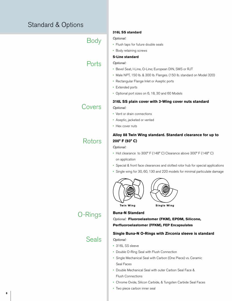
S-Line standard
Optional:
• Bevel Seat, I-Line, Q-Line; European DIN, SMS or RJT
• Male NPT, 150 lb. & 300 lb. Flanges. (150 lb. standard on Model 320)
• Rectangular Flange Inlet or Aseptic ports
• Extended ports
• Optional port sizes on 6, 18, 30 and 60 Models
316L SS plain cover with 3-Wing cover nuts standard
Optional:
• Vent or drain connections
• Aseptic, jacketed or vented
• Hex cover nuts
316L SS standard
Optional:
• Flush taps for future double seals
• Body retaining screws
Alloy 88 Twin Wing standard. Standard clearance for up to
200° F (93° C)
Optional:
• Hot clearance to 300° F (148° C) Clearance above 300° F (148° C)
on application
• Special & front face clearances and slotted rotor hub for special applications
• Single wing for 30, 60, 130 and 220 models for minimal particulate damage
Single Buna-N O-Rings with Zirconia sleeve is standard
Optional:
• 316L SS sleeve
• Double O-Ring Seal with Flush Connection
• Single Mechanical Seal with Carbon (One Piece) vs. Ceramic
Seal Faces
• Double Mechanical Seal with outer Carbon Seal Face &
Flush Connections
• Chrome Oxide, Silicon Carbide, & Tungsten Carbide Seal Faces
• Two piece carbon inner seal
Buna-N Standard
Optional: Fluoroelastomer (FKM), EPDM, Silicone,
Perfluoroelastomer (FFKM), FEP Encapsulates
Body
Ports
Covers
Rotors
O-Rings
Seals
Single WingTwin Wing
Standard & Options
9
316L SS plain cover with 3-Wing cover nuts standard
Optional:
• Vent or drain connections
• Aseptic, jacketed or vented
• Hex cover nuts
316L SS standard
Optional:
• Flush taps for future double seals
• Body retaining screws
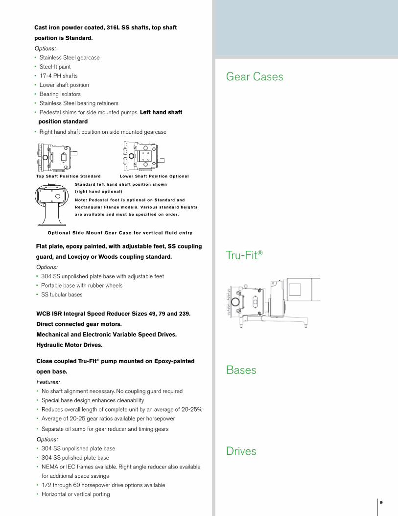
Optional Side Mount Gear Case for vert ical f luid entry
Cast iron powder coated, 316L SS shafts, top shaft
position is Standard.
Options:
• Stainless Steel gearcase
• Steel-It paint
• 17-4 PH shafts
• Lower shaft position
• Bearing Isolators
• Stainless Steel bearing retainers
• Pedestal shims for side mounted pumps. Left hand shaft
position standard
• Right hand shaft position on side mounted gearcase
Flat plate, epoxy painted, with adjustable feet, SS coupling
guard, and Lovejoy or Woods coupling standard.
Options:
• 304 SS unpolished plate base with adjustable feet
• Portable base with rubber wheels
• SS tubular bases
WCB ISR Integral Speed Reducer Sizes 49, 79 and 239.
Direct connected gear motors.
Mechanical and Electronic Variable Speed Drives.
Hydraulic Motor Drives.
Standard left hand shaft posit ion shown
(r ight hand optional)
Note: Pedestal foot is optional on Standard and
Rectangular Flange models. Various standard heights
are avai lable and must be specif ied on order .
LISTEN INNOVATE DE-LIVER
Top Shaft Posit ion Standard Lower Shaft Posit ion Optional
Gear Cases
Tru-Fit®
Gear Cases
Bases
Drives
Close coupled Tru-Fit® pump mounted on Epoxy-painted
open base.
Features:
• No shaft alignment necessary. No coupling guard required
• Special base design enhances cleanability
• Reduces overall length of complete unit by an average of 20-25%
• Average of 20-25 gear ratios available per horsepower
• Separate oil sump for gear reducer and timing gears
Options:
• 304 SS unpolished plate base
• 304 SS polished plate base
• NEMA or IEC frames available. Right angle reducer also available
for additional space savings
• 1/2 through 60 horsepower drive options available
• Horizontal or vertical porting
10
NOTE: Dimension “2X” appl ies for Bevel Seat , “S-Clamp”, “Q-Clamp”, 15I and 14I f i t t ings (except 320U1) .
*NOTE: CP4 is the maximum dimension for al l vented and jacketed cover options.
Contact Application Engineering for Universal 1 Series Aseptic Models.
SizeModel CP CP4 I O PORT
Size
U +.000 - .001
2X WTLB S/ KG
006-U1I N 12.04 15.25 7.66 4.21 1 1/2" .875 6.97 52
mm 306 387 194 107 --- 22.23 177 24
015-U1I N 12.04 15.25 7.66 4.21 1 1/2" .875 6.97 52
mm 306 387 194 107 --- 22.23 177 24
018 U1I N 12.46 15.67 7.66 4.21 1 1/2" .875 7.09 54
mm 316 398 194 107 --- 22.23 180 24
030-U1I N 14.58 17.67 8.83 5.21 1 1/2" 1 .250 8.50 100
mm 370 449 224 132 --- 31.75 216 45
040-U1I N 14.96 18.05 8.83 5.21 2" 1.250 8.62 106
mm 380 458 224 132 --- 31.75 219 48
060-U1I N 18.91 22.07 10.99 7.31 2 1/2" 1 .625 10.75 225
mm 480 561 279 186 --- 41.28 273 116
130-U1I N 19.85 23.01 10.99 7.31 3" 1.625 10.75 260
mm 504 584 279 186 --- 41.28 273 118
220-U1I N 23.37 27.87 14.80 9.38 4" 2.000 13.25 450
mm 594 708 376 238 --- 50.80 337 204
320-U1I N 30.17 --- 17.80 10.38 6" 150# FLG 2.375 16.00 795
mm 766 --- 452 264 --- 60.45 406 361
D I M E N S IONAL DATA
11
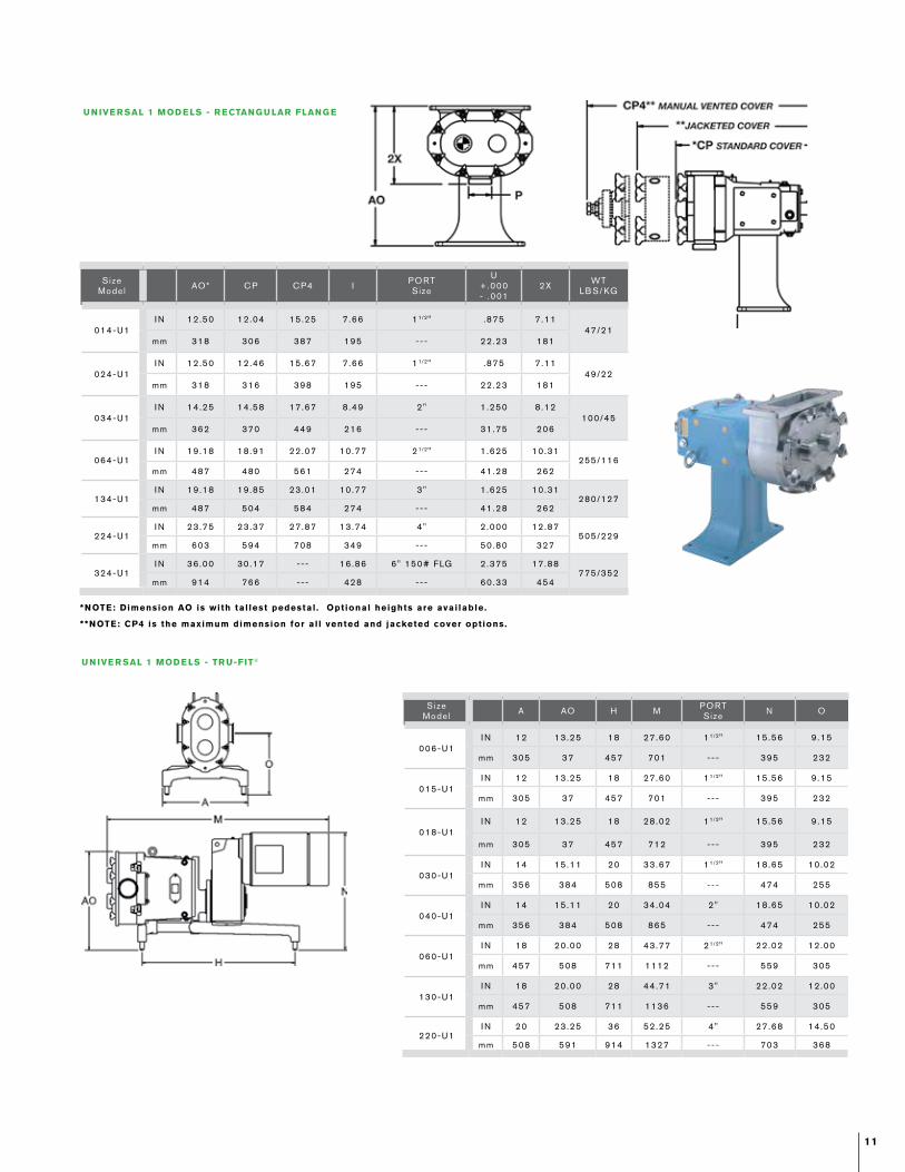
*NOTE: Dimension AO is with tal lest pedestal . Optional heights are avai lable.
**NOTE: CP4 is the maximum dimension for al l vented and jacketed cover options.
SizeModel AO* CP CP4 I PORT
Size
U +.000 - .001
2X WTLB S/ KG
014-U1I N 12.50 12.04 15.25 7.66 1 1/2" .875 7.11
47/21mm 318 306 387 195 --- 22.23 181
024-U1I N 12.50 12.46 15.67 7.66 1 1/2" .875 7.11
49/22mm 318 316 398 195 --- 22.23 181
034-U1I N 14.25 14.58 17.67 8.49 2" 1.250 8.12
100/45mm 362 370 449 216 --- 31.75 206
064-U1I N 19.18 18.91 22.07 10.77 2 1/2" 1 .625 10.31
255/116mm 487 480 561 274 --- 41.28 262
134-U1I N 19.18 19.85 23.01 10.77 3" 1.625 10.31
280/127mm 487 504 584 274 --- 41.28 262
224-U1I N 23.75 23.37 27.87 13.74 4" 2.000 12.87
505/229mm 603 594 708 349 --- 50.80 327
324-U1I N 36.00 30.17 --- 16.86 6" 150# FLG 2.375 17.88
775/352mm 914 766 --- 428 --- 60.33 454
SizeModel A AO H M PORT
Size N O
006-U1I N 12 13.25 18 27.60 1 1/2" 15.56 9.15
mm 305 37 457 701 --- 395 232
015-U1I N 12 13.25 18 27.60 1 1/2" 15.56 9.15
mm 305 37 457 701 --- 395 232
018-U1I N 12 13.25 18 28.02 1 1/2" 15.56 9.15
mm 305 37 457 712 --- 395 232
030-U1I N 14 15.11 20 33.67 1 1/2" 18.65 10.02
mm 356 384 508 855 --- 474 255
040-U1I N 14 15.11 20 34.04 2" 18.65 10.02
mm 356 384 508 865 --- 474 255
060-U1I N 18 20.00 28 43.77 2 1/2" 22.02 12.00
mm 457 508 711 1112 --- 559 305
130-U1I N 18 20.00 28 44.71 3" 22.02 12.00
mm 457 508 711 1136 --- 559 305
220-U1I N 20 23.25 36 52.25 4" 27.68 14.50
mm 508 591 914 1327 --- 703 368
U N IVE R SAL 1 MOD E LS - R ECTANG U LAR FLANG E
U N IVE R SAL 1 MOD E LS - TR U-FIT®
SPX FLOW, Inc. reserves the right to incorporate our latest design and material changes without notice or obligation.
Design features, materials of construction and dimensional data, as described in this bulletin, are provided for your information only and should not be relied upon unless confirmed
in writing. Please contact your local sales representative for product availability in your region. For more information visit www.spxflow.com.
The green “ ” and “ ” are trademarks of SPX FLOW, Inc.
ISSUED 12/2017 FH-1701
COPYRIGHT © 2017 SPX FLOW, Inc.
S PX FLOW
611 Sugar Creek Road
Delavan, WI 53115
P: (262) 728-1900 or (800) 252-5200
Based in Charlotte, North Carolina, SPX FLOW, Inc. (NYSE: FLOW) is a multi-industry manufacturing leader. For more information, please
visit www.spxflow.com
When it is time to repair ...
SPX FLOW offers the following options – you pick the one that meets your needs.Factory Remanufacturing Program
• No need to return your pump until you
receive your new replacement pump.
• Substantial savings over new pump.
• All remanufactured pumps must pass a
25 point inspection process and undergo
performance testing.
• Only OEM genuine parts are used in the
remanufacturing process and you receive
a guaranteed warranty and quality certificate
with each pump.
• New pumps eligible for Remanufacturing
Program twice.
Factory Inspect and Advise Program
• Return your pump for complete factory
inspection.
• Cost effective options to match your
performance/budget needs.
• Your pump body may be remachined up to 6
times.
• Replacement rotors and parts available.
• Factory warranty.
SPX FLOW Certif ied Pump Repair Centers
• Local distributors with factory trained and
certified service technicians.
• Quick local response.
• Genuine WCB parts.
• Flexible repair programs to meet your needs.
• Local warranty.
Universal 1 SeriesROTARY POS ITIVE
D I S PLACE M E NT PU M PS