vi biofloc production systems for aquaculture · 1aquaculture assessments, llc srac publication no....
TRANSCRIPT
1Aquaculture Assessments, LLC
SRAC Publication No. 4503
April 2013
Biofloc Production Systems for AquacultureJohn A. Hargreaves1
VIPR
Southern regional aquaculture center
Biofloc systems were developed to improve environmental control over pro-duction. In places where water is scarce or land is expensive, more intensive forms of aquaculture must be practiced for cost-effective production. There are strong economic incentives for an aqua-culture business to be more efficient with production inputs, especially the most costly (feed) and most limiting (water or land). High-density rearing of fish typically requires some waste treatment infrastructure. At its core, biofloc is a waste treatment system.
Biofloc systems were also developed to prevent the introduction of disease to a farm from incoming water. In the past, standard operation of shrimp ponds included water exchange (typically 10 percent per day) as a method to control water quality. In estuarine areas with many shrimp farms practicing water exchange, disease would spread among farms. Reducing water exchange is an obvious strategy for improving farm biosecurity. Shrimp farming began moving toward more closed and intensive production where waste treatment is more internalized.
Biofloc systems use a counter-intuitive approach— allow or encourage solids and the associated microbial community to accumulate in water. As long as there is sufficient mixing and aeration to maintain an active floc in suspension, water quality can be controlled. Managing biofloc systems is not as straightforward as that, however, and some degree of technical sophistication is required for the system to be fully functional and most productive.
Composition and nutritional value of bioflocs
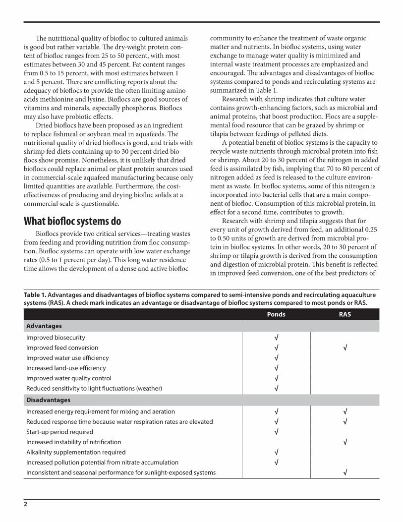
Bioflocs are aggregates (flocs) of algae, bacteria, proto-zoans, and other kinds of particulate organic matter such as feces and uneaten feed. Each floc is held together in a loose matrix of mucus that is secreted by bacteria, bound by filamentous microorganisms, or held by electrostatic attraction (Fig. 1). The biofloc community also includes animals that are grazers of flocs, such as some zooplank-ton and nematodes. Large bioflocs can be seen with the naked eye, but most are microscopic. Flocs in a typical greenwater biofloc system are rather large, around 50 to 200 microns, and will settle easily in calm water.
Figure 1. An individual biofloc from an indoor system. The scale bar is 100 microns.
2
The nutritional quality of biofloc to cultured animals is good but rather variable. The dry-weight protein con-tent of biofloc ranges from 25 to 50 percent, with most estimates between 30 and 45 percent. Fat content ranges from 0.5 to 15 percent, with most estimates between 1 and 5 percent. There are conflicting reports about the adequacy of bioflocs to provide the often limiting amino acids methionine and lysine. Bioflocs are good sources of vitamins and minerals, especially phosphorus. Bioflocs may also have probiotic effects.
Dried bioflocs have been proposed as an ingredient to replace fishmeal or soybean meal in aquafeeds. The nutritional quality of dried bioflocs is good, and trials with shrimp fed diets containing up to 30 percent dried bio-flocs show promise. Nonetheless, it is unlikely that dried bioflocs could replace animal or plant protein sources used in commercial-scale aquafeed manufacturing because only limited quantities are available. Furthermore, the cost-effectiveness of producing and drying biofloc solids at a commercial scale is questionable.
What biofloc systems doBioflocs provide two critical services—treating wastes
from feeding and providing nutrition from floc consump-tion. Biofloc systems can operate with low water exchange rates (0.5 to 1 percent per day). This long water residence time allows the development of a dense and active biofloc
community to enhance the treatment of waste organic matter and nutrients. In biofloc systems, using water exchange to manage water quality is minimized and internal waste treatment processes are emphasized and encouraged. The advantages and disadvantages of biofloc systems compared to ponds and recirculating systems are summarized in Table 1.
Research with shrimp indicates that culture water contains growth-enhancing factors, such as microbial and animal proteins, that boost production. Flocs are a supple-mental food resource that can be grazed by shrimp or tilapia between feedings of pelleted diets.
A potential benefit of biofloc systems is the capacity to recycle waste nutrients through microbial protein into fish or shrimp. About 20 to 30 percent of the nitrogen in added feed is assimilated by fish, implying that 70 to 80 percent of nitrogen added as feed is released to the culture environ-ment as waste. In biofloc systems, some of this nitrogen is incorporated into bacterial cells that are a main compo-nent of biofloc. Consumption of this microbial protein, in effect for a second time, contributes to growth.
Research with shrimp and tilapia suggests that for every unit of growth derived from feed, an additional 0.25 to 0.50 units of growth are derived from microbial pro-tein in biofloc systems. In other words, 20 to 30 percent of shrimp or tilapia growth is derived from the consumption and digestion of microbial protein. This benefit is reflected in improved feed conversion, one of the best predictors of
Table 1. Advantages and disadvantages of biofloc systems compared to semi-intensive ponds and recirculating aquaculture systems (RAS). A check mark indicates an advantage or disadvantage of biofloc systems compared to most ponds or RAS.
Ponds RAS
Advantages
Improved biosecurity √Improved feed conversion √ √Improved water use efficiency √Increased land-use efficiency √Improved water quality control √Reduced sensitivity to light fluctuations (weather) √
Disadvantages
Increased energy requirement for mixing and aeration √ √Reduced response time because water respiration rates are elevated √ √Start-up period required √Increased instability of nitrification √Alkalinity supplementation required √Increased pollution potential from nitrate accumulation √Inconsistent and seasonal performance for sunlight-exposed systems √
3
system profitability and business sustainability. However, the value of flocs in nutrition is limited at the highest levels of production intensity because the contribution of feed to growth of cultured animals is overwhelming.
Suitable culture speciesA basic factor in designing a biofloc system is the spe-
cies to be cultured. Biofloc systems work best with species that are able to derive some nutritional benefit from the direct consumption of floc. Biofloc systems are also most suitable for species that can tolerate high solids concen-tration in water and are generally tolerant of poor water quality. Species such as shrimp and tilapia have physi-ological adaptations that allow them to consume biofloc and digest microbial protein, thereby taking advantage of biofloc as a food resource. Nearly all biofloc systems are used to grow shrimp, tilapia, or carps. Channel catfish and hybrid striped bass are examples of fish that are not good candidates for biofloc systems because they do not tolerate water with very high solids concentrations and do not have adaptations to filter solids from water.
Basic types of biofloc systemsFew types of biofloc systems have been used in com-
mercial aquaculture or evaluated in research. The two basic types are those that are exposed to natural light and those that are not. Biofloc systems exposed to natural light include outdoor, lined ponds or tanks for the culture of shrimp or tilapia and lined raceways for shrimp culture in green-houses. A complex mixture of algal and bacterial processes control water quality in such “greenwater” biofloc systems. Most biofloc systems in commercial use are greenwater.
However, some biofloc systems (raceways and tanks) have been installed in closed buildings with no exposure to natural light. These systems are operated as “brown- water” biofloc systems, where only bacterial processes control water quality.
The specifications and performance of various biofloc production systems are discussed in more detail at the end of this publication.
Mixing and aerationIntensive turbulent mixing is an essential requirement
of biofloc systems. Solids must be suspended in the water column at all times or the system will not function. With-out mixing, bioflocs settle out of suspension and may form piles that rapidly consume nearby dissolved oxygen. These anaerobic zones can lead to the release of hydrogen sulfide, methane, and ammonia that are highly toxic to shrimp and fish. Solids can be removed by periodic flushing or by pumping sludge from the pond center. Sludge banks are
resuspended periodically by moving and repositioning paddlewheel aerators. Creating turbulent conditions in relatively small tanks or raceways is much easier than in larger outdoor ponds. Excessive turbulence can present a challenge to cultured animals by making it difficult for fish or shrimp to locate feed.
Compared to water in aquaculture ponds or most recirculating systems, water in biofloc systems has an elevated respiration rate caused by a high concentration of suspended solids. In intensive, greenwater raceways for shrimp, water respiration rates range from 2 to 2.5 mg O2/L per hour, although it can be as high as 6 mg O2/L per hour. This does not include respiration by the fish or shrimp crop, which brings overall respiration to 5 to 8 mg O2/L per hour. Water respiration in indoor brownwater biofloc systems is normally about 6 mg O2/L per hour. It is absolutely essential to provide sufficient aeration or oxygenation to meet this high oxygen demand and to maintain oxygen concentration at safe levels. These high respiration rates also indicate that the response time in the event of a system failure is very short, often less than 1 hour. Thus, monitoring, alarms, and emergency power systems are required elements of biofloc systems.
In practice, aeration is used to supply oxygen and provide mixing. Although paddlewheel aerators supply oxygen efficiently, they are not ideal for pond mixing. Devices that provide only mixing are rarely used. Various configurations of aeration equipment are possible, depend-ing on the specific form of biofloc system. In lined ponds or tanks, multiple paddlewheel aerators are arrayed to provide whole-pond, circular mixing. Shrimp raceways in greenhouses often use banks of airlift pumps placed at intervals around raceways to aerate and circulate water. Diffused aeration can be used in small tanks. Devices that circulate water at low head, such as low-speed paddle-wheels and airlift pumps, can be used.
The power requirement for mixing and aeration far exceeds that for conventional ponds and most recirculat-ing systems. Biofloc shrimp ponds are aerated with 25 to 35 hp/ha, and some intensive tilapia systems are aerated with 100 to 150 hp/ha. These intensive aeration rates could not be applied to earthen ponds without significant ero-sion; thus, most biofloc systems are lined. Biofloc systems are not a good choice in areas where power supplies are unreliable or electricity is expensive.
Effect of feeding rate and the greenwater-to-biofloc transition
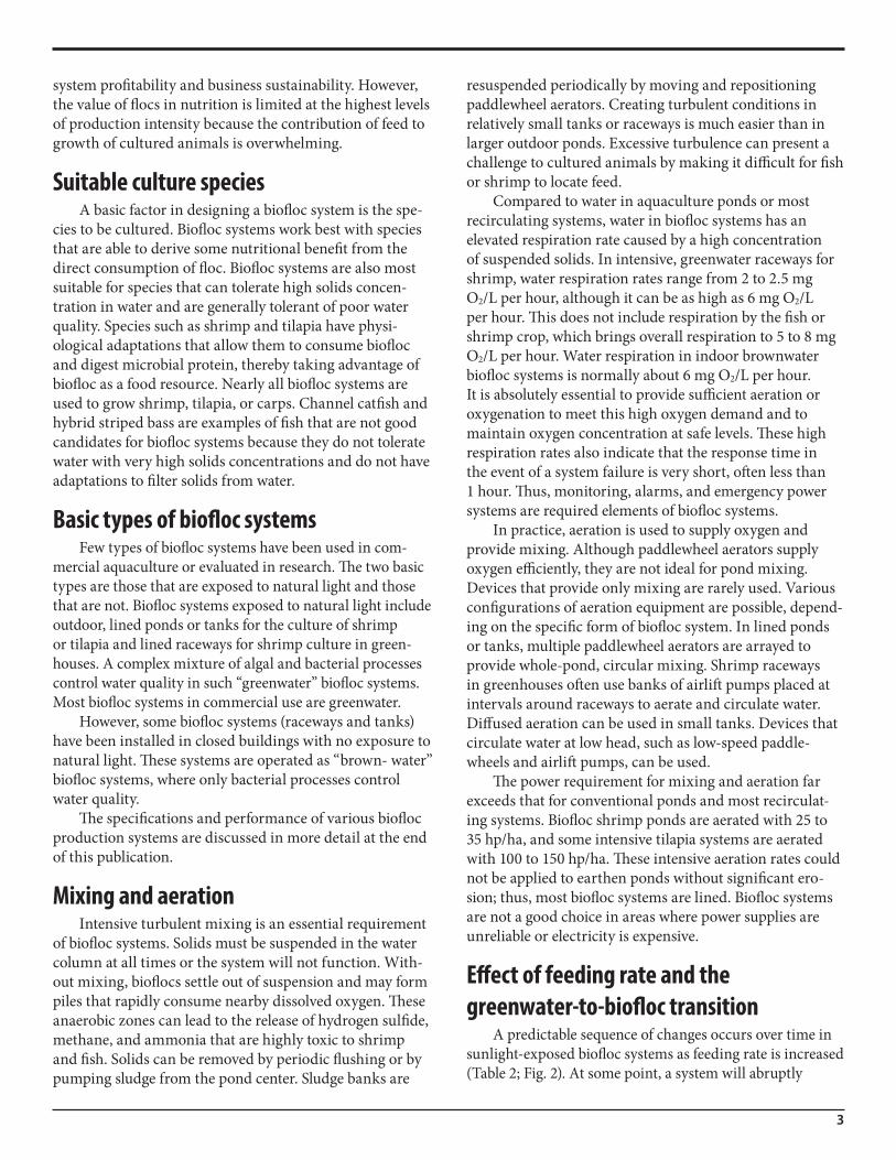
A predictable sequence of changes occurs over time in sunlight-exposed biofloc systems as feeding rate is increased (Table 2; Fig. 2). At some point, a system will abruptly
4
transition from a greenwater, algal system to a brownwater, bacterial system. The transi-tion described here is based on conditions in an inten-sive greenhouse raceway for shrimp. Conditions leading to the transition from green-water to brownwater biofloc will vary somewhat in differ-ent system types (i.e., ponds, raceways, tanks).
As daily feeding rate increases from 100 to 200 kg/ha (10 to 20 g/m2), the water will appear green with a dense algae bloom. Algal uptake is the main mechanism for ammonia control. The aerator power required at this feeding rate is about 25 to 30 hp/ha.
At a daily feeding rate of 300 kg/ha, there is an abrupt shift when the lack of light at very high algal density hin-ders photosynthesis. Bacteria begin to grow and bioflocs develop, as indicated by an increase in suspended solids concentration (250 to 500 mg/L) and the associated rapid increase in water respiration (6 mg O2/L per hour). This requires a five-fold increase in aerator power from 30 to 150 hp/ha to match the oxygen demand. Most of this increased energy demand is required to maintain bioflocs in suspension. Despite these changes, the water continues
Figure 2. The Microbial Community Color Index (MCCI) indicating the transition from an algal to a bacterial system as feed loading increases. The transition between algal and bacterial systems occurs at a feed loading of 300 to 500 kg/ha per day, indicated by an MCCI between 1 and 1.2 (courtesy of D.E. Brune and K. Kirk).
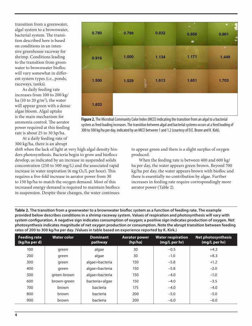
Table 2. The transition from a greenwater to a brownwater biofloc system as a function of feeding rate. The example provided below describes conditions in a shrimp raceway system. Values of respiration and photosynthesis will vary with system configuration. A negative sign indicates consumption of oxygen; a positive sign indicates production of oxygen. Net photosynthesis indicates magnitude of net oxygen production or consumption. Note the abrupt transition between feeding rates of 200 to 300 kg/ha per day. (Values in table based on experience reported by K. Kirk.)
Feeding rate (kg/ha per d)
Water color Dominant pathway
Aerator power (hp/ha)
Water respiration (mg/L per hr)
Net photosynthesis (mg/L per hr)
100 green algae 30 –0.5 +4.2
200 green algae 30 –1.0 +8.3
300 green algae+bacteria 150 –5.8 +1.2
400 green algae+bacteria 150 –5.8 –2.0
500 green-brown algae+bacteria 150 –4.0 –1.0
600 brown-green bacteria+algae 150 –4.0 –3.5
700 brown bacteria 175 –4.0 –4.0
800 brown bacteria 200 –5.0 –5.0
900 brown bacteria 200 –6.0 –6.0
to appear green and there is a slight surplus of oxygen produced.
When the feeding rate is between 400 and 600 kg/ha per day, the water appears green-brown. Beyond 700 kg/ha per day, the water appears brown with biofloc and there is essentially no contribution by algae. Further increases in feeding rate require correspondingly more aerator power (Table 2).
5
The transition is sometimes difficult to perceive visu-ally. The functional shift from a surplus to a deficit of oxygen occurs while the water continues to look green. The color change from green to brown takes place after the transition from a mostly algal to a mostly bacterial biofloc system has occurred. So water color is not an accurate indicator of system status. At high aeration rates, the appearance of large amounts of surface foam is a good sign of a system in transition.
Ammonia dynamicsA major goal of water quality management in any
aquatic animal production system is maintaining ammo-nia concentration below toxic levels. In biofloc systems, there are three main processes that control ammonia—algal uptake, bacterial assimilation, and nitrification. The transformations and dynamics of ammonia in biofloc sys-tems are complex, involving interplay among the algae and bacteria that compete for ammonia. The relative impor-tance of each process depends on many factors, among them the daily feeding rate, suspended solids (biofloc) concentration, ammonia concentration, light intensity, and input carbon-to-nitrogen (C:N) ratio.
Algal uptakeIn any biofloc system exposed to sunlight, a dense
algal bloom will develop in response to nutrient load-ing from feeding. Nutrients released from decomposing organic matter (including dead algae, fecal solids, and uneaten feed) are rapidly taken up and stored in algae cells. The rate of algal uptake in biofloc systems is mainly influenced by underwater light intensity. In biofloc systems with a primary dependence on algal uptake, extended periods of cloudy weather can cause spikes of ammonia concentration. The accumulation of biofloc solids shades out algae and limits ammonia uptake. Daily fluctuation in dissolved oxygen concentration and pH, despite intensive aeration, is another characteristic of biofloc systems where algal activity is predominant. Generally, at daily feeding rates less than 300 kg/ha (30 g/m2), algal activity is the major factor controlling water quality.
Bacterial assimilationMany of the early names for biofloc systems included
the word “heterotrophic,” which describes a group of bacteria that, by definition, obtains carbon from organic sources. Despite large inputs of feed to intensive systems, the growth of heterotrophic bacteria in biofloc systems is limited by dissolved organic carbon. To stimulate produc-tion of heterotrophic bacteria, the C:N ratio of inputs is raised by adding a supplemental source of carbohydrate or reducing feed protein level. By this manipulation, hetero-
trophic bacteria create a demand for nitrogen (as ammo-nia) because organic carbon and inorganic nitrogen are generally taken up in a fixed ratio that reflects the compo-sition and requirement of bacterial cells. Thus, ammonia can be controlled by adding organic carbon to stimulate the growth of heterotrophic bacteria.
Similar to algae, ammonia is “immobilized” while packaged in heterotrophic bacterial cells as protein. Because the growth rate of heterotrophic bacteria is so much greater than that of nitrifying bacteria, ammonia control through immobilization by heterotrophic bacteria occurs rapidly, usually within hours or days if a sufficient quantity of simple organic carbon (e.g., sugar or starch) is added. The packaging of nitrogen in bacterial cells is temporary because cells turn over rapidly and release nitrogen as ammonia when they decompose. Cells are also consumed by fish or removed as excess solids. As with nitrogen assimilated by algae, microbial protein in flocs containing heterotrophic bacteria can serve as a supple-mental source of nutrition for fish and shrimp.
NitrificationThe two-step oxidation of ammonia to nitrate is called
nitrification. The bacterial process transforms a toxic form of nitrogen (ammonia) to one that is toxic only at high concentrations (nitrate). Over time, nitrate accumulates in low-exchange biofloc systems. In contrast to rapid cycling between dissolved ammonia and algal or bacterial cells, nitrification is responsible for the long-term, ultimate fate of a large fraction (25 to 50 percent) of the nitrogen from feed added to intensive biofloc systems. This mechanism becomes relatively more important as production intensity, as measured by daily feeding rate, increases.
To simplify the nitrogen dynamics in biofloc systems with low water exchange: Waste nitrogen is repeatedly cycled between dissolved ammonia and solids of algae or bacteria. If solids are removed, a significant fraction of added nitrogen can be taken out of the system. If solids are not removed, a large proportion of nitrogen (as ammonia) is ultimately oxidized to nitrate, which accumulates.
Management strategies for ammonia control in biofloc systemsBalancing input C:N ratio
In biofloc systems, a major factor that controls ammo-nia concentration is the C:N ratio of feed and other inputs. A feed with a 30 to 35 percent protein concentration has a relatively low C:N ratio, about 9 to 10:1. Increasing the C:N ratio of inputs to 12 to 15:1 favors the heterotrophic pathway for ammonia control. The low C:N ratio of feed can be augmented by adding supplemental materials with
6
high C:N ratio. Or, the input C:N ratio can be increased by reducing feed protein content. Ammonia uptake by heterotrophic bacteria occurs rapidly after carbohydrate supplementation. Ammonia control through the hetero-trophic pathway is often more stable and reliable than algal uptake or nitrification.
Many practical and processed materials have been used as carbon sources in biofloc systems, including grain pellets, molasses, sugar cane bagasse, and chopped hay, among others. Carbohydrate materials should be low-cost and convenient. Organic matter that breaks down easily and quickly is best. Heterotrophic bacteria in biofloc sys-tems can act on simple organic matter rapidly, within min-utes to hours. Simple carbohydrates such as sugar (sucrose or dextrose) or starch will have the quickest effect. The best carbon source to add during system start-up, when the most rapid response is needed, is simple sugar.
To promote exclusive control of ammonia concentra-tion by the heterotrophic pathway, carbohydrate additions must be made in accordance with feeding rate. For every 1 kg of 30 to 38 percent protein feed added, add 0.5 to 1 kg of a carbohydrate source such as sugar. More carbohydrate is needed at the higher protein level. It is clear that relatively large quantities of carbohydrate must be added to control ammonia concentration this way. Less carbohydrate can be added if other ammonia removal pathways are operat-ing simultaneously in a biofloc system.
There are several drawbacks to continually add-ing organic carbon to control ammonia. This pathway encourages the production of bacterial solids, which accu-mulate. If not controlled, solids concentration may reach levels that cause gill clogging. More oxygen will be needed to support the respiratory demands of a greater bacte-rial load, and additional energy is needed to keep solids in suspension. High rates of water respiration (oxygen consumption) reduce response time in the event of system failure. Capacity must be added to remove, treat, and dispose of accumulated solids.
Ongoing carbon supplementation is required to con-trol ammonia with this approach. In order to stop carbon supplementation, a system must be “weaned.” Stopping the supplemental carbon abruptly before the nitrification pathway is sufficiently developed will lead to water quality instability and potentially detrimental spikes of ammo-nia and/or nitrite. Once carbon supplementation ceases, superintensive biofloc systems naturally tend toward the nitrification pathway of ammonia control.
Promoting suspended-growth nitrificationIn contrast to the previous approach, encouraging
suspended-growth nitrification requires no supplemental
carbohydrate or consideration of input C:N ratio. This approach emphasizes nitrification over other pathways for ammonia control, using the nitrifying bacteria that are attached to suspended solids (and surfaces of the culture unit) to control ammonia. Well-mixed biofloc systems without carbohydrate supplementation tend to develop this mechanism of long-term ammonia control naturally.
One of the main disadvantages of this approach is the consumption of alkalinity by nitrification. All three pro-cesses that control ammonia in biofloc systems consume alkalinity, but nitrification is responsible for most of those losses. Denitrification reactors can be used to recover some of the lost alkalinity, but they increase production cost. Regular liming is a requirement of biofloc systems managed with this approach.
System management during start-upDuring start-up, changes in water quality in biofloc
systems are remarkably similar to those in conventional recirculating systems. System start-up is characterized by time lags in peak concentrations of ammonia and then nitrite as the different populations of bacteria develop. If the feeding rate is increased too rapidly, concentrations of ammonia or (especially) nitrite can increase to the point where they become toxic and affect fish growth, feed con-version, disease resistance, or—in some cases—survival.
The duration of start-up depends on a wide range of factors, including temperature, feeding rate scheduling, and pre-seeding of the system with the right kind and quantity of microbes. Acclimation protocols for biofloc systems have not been standardized, and many system operators have developed their own techniques through hard-won experience. Nitrifying bacteria can be grown in stand-alone tanks at high concentration and then added to rearing tanks before stocking. Adding sludge or water from a previously acclimated system is also an effective approach to “seeding” a new tank or pond, although the practice represents a biosecurity risk.
Ammonia or nitrite peaks during start-up can be avoided or minimized by adding carbohydrate. To neutralize 1 mg/L of ammonia (as N), add 15 to 20 mg/L of sugar. Carbohydrate added during start-up to keep ammonia concentration low can extend the time required for system acclimation. Once the system is acclimated, further supplementation with carbon is optional because nitrifying bacteria are able to keep ammonia and nitrite concentrations at safe levels. Carbohydrate also can be added occasionally, as needed during the culture period, when ammonia concentration spikes.
7
Solids managementIn biofloc systems, waste solids are allowed to accu-
mulate and additional solids are encouraged by intensive aeration and carbohydrate additions. Over time, and with sufficient mixing, solids can accumulate to undesir-ably high levels (2,000 to 3,000 mg/L). Biofloc systems are typically operated at suspended solids concentrations less than 1,000 mg/L and most often less than 500 mg/L. A suspended solids concentration of 200 to 500 mg/L is sufficient for good system functionality and will control ammonia without excessive water respiration. The best feed consumption in shrimp raceway biofloc systems occurs at a solids concentration of 100 to 300 mg/L.
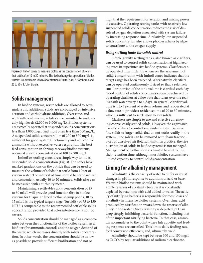
Imhoff or settling cones are a simple way to index suspended solids concentration (Fig. 3). The cones have marked graduations on the outside that can be used to measure the volume of solids that settle from 1 liter of system water. The interval of time should be standardized and convenient, usually 10 to 20 minutes. Solids also can be measured with a turbidity meter.
Maintaining a settleable solids concentration of 25 to 50 mL/L will provide good functionality in biofloc systems for tilapia. In lined biofloc shrimp ponds, 10 to 15 mL/L is the typical target range. Turbidity of 75 to 150 NTU is comparable to the recommended settleable solids concentration provided that color interference is not too severe.
Solids concentration should be managed as a compro-mise between the functionality of the biofloc system as a biofilter (for ammonia control) and the oxygen demand of the water, which increases directly with solids concentra-tion. In other words, the concentration should be as low as possible to provide sufficient biofiltration and not so
high that the requirement for aeration and mixing power is excessive. Operating rearing tanks with relatively low suspended solids concentration reduces the risk of dis-solved oxygen depletion associated with system failure by increasing response time. A relatively low suspended solids concentration also allows photosynthesis by algae to contribute to the oxygen supply.
Using settling tanks for solids controlSimple gravity settling tanks, also known as clarifiers,
can be used to control solids concentration at high feed-ing rates in superintensive biofloc systems. Clarifiers can be operated intermittently whenever the assessment of solids concentration with Imhoff cones indicates that the target range has been exceeded. Alternatively, clarifiers can be operated continuously if sized so that a relatively small proportion of the tank volume is clarified each day. Good control of solids concentration can be achieved by operating clarifiers at a flow rate that turns over the rear-ing tank water every 3 to 4 days. In general, clarifier vol-ume is 1 to 5 percent of system volume and is operated at a flow rate to provide a residence time of 20 to 30 minutes, which is sufficient to settle most heavy solids.
Clarifiers are simple to use and effective at remov-ing coarse, easily settled solids. However, the aggressive use of clarifiers to control suspended solids may leave fine solids or larger solids that do not settle readily in the system. Fine solids can be removed with foam fraction-ators or dissolved air flotation units. In practice, the size distribution of solids in biofloc systems is not managed. Management of biofloc solids is limited to controlling their retention time, although most biofloc systems have limited capacity to control solids concentration.
Liming for alkalinity managementAlkalinity is the capacity of water to buffer or resist
changes in pH in response to additions of acid or base. Water in biofloc systems should be maintained with ample reserves of alkalinity because it is constantly depleted by reactions with acid added to water. The activ-ity of nitrifying bacteria is responsible for most losses of alkalinity in intensive biofloc systems. Over time, acid produced by nitrification wears down the reserve of alka-linity in the water. Once alkalinity is depleted, pH can drop steeply, inhibiting bacterial function, including that of the important nitrifying bacteria. In that case, ammo-nia accumulates to the point where fish appetite and feed-ing response are curtailed. This limits daily feeding rate, feed conversion efficiency, and, ultimately, yield.
Alkalinity should be kept between 100 and 150 mg/L as CaCO3 by regular additions of sodium bicarbonate.
Figure 3. Imhoff cones to measure biofloc as the concentration of solids that settle after 10 to 20 minutes. The desired range for operation of biofloc systems is a settleable solids concentration of 10 to 15 mL/L for shrimp and 25 to 50 mL/L for tilapia.
8
Other liming agents are less suitable. Caustic agents (e.g., calcium hydroxide) can be used with a continuous dosing system. In intensive, nitrification-dominated biofloc sys-tems, every kilogram of feed added to the system should be supplemented with 0.25 kilogram of sodium bicarbon-ate. Even with regular additions, facility operators should have a regular (at least weekly) monitoring program to evaluate alkalinity.
Denitrification and sludge treatmentAlkalinity can be recovered in denitrification units.
Nitrate accumulates in most intensive biofloc systems because of ongoing nitrification. If unchecked, nitrate concentration reflects the cumulative feed loading to the system. Nitrate accumulation can be tempered by dilution through water exchange, but this defeats the purpose of intensive water use and reduces biosecurity.
Denitrification units are used as part of a water con-servation and biosecurity strategy where it is also a cost issue to conserve salts. This is an acute need in superinten-sive saltwater systems for shrimp, especially those located inland. Furthermore, the discharge of saline effluent is restricted or regulated in many areas, especially inland.
Denitrification units are operated under generally quiescent and anoxic conditions. Solids can be shunted to a side-stream tank and allowed to accumulate. A low flow of culture water, sufficient to provide a detention time of 1 to 2 days, is adequate to control nitrate con-centration. Solids accumulation will reach a steady state. Under anoxic conditions, the steady supply of nitrate is used as an oxidant to continually oxidize organic matter, although simple organic carbon (sugar) may be needed to bolster the process. Bicarbonate is released by bacteria as a by-product of this process. Thus, the alkalinity that was lost from nitrification can be recovered by denitrification.
Additional water can be conserved by using a sequencing batch reactor to reduce the volume of sludge and mass of solids discharged from an intensive aquacul-ture facility. The specific sequence of operational steps is:
■ Fill. A batch of sludge collected from settling tanks is added to the reactor. (Closed reactors work best but are not necessary; any tank or vessel is suit-able.)
■ React. Solids and residual bioflocs are vigorously mixed and aerated for ½ to 1 day to promote solids degradation.
■ Settle. Mixing and aeration are stopped. Most solids will settle quickly and nearly all within 2 to 3 hours.
■ Decant. The clean water that overlies the settled sol-ids is drawn off and returned to the biofloc system.
This sequence is repeated for each additional batch of sludge. Water with a rotten-egg odor, indicating hydrogen sulfide, should not be returned to culture tanks before it is vigorously aerated.
One variation of the process is to extend the settling period. Very quickly after settling, respiration by settled biofloc solids will fully consume all oxygen in the water. Anoxic conditions allow other reactions to occur, includ-ing denitrification. Operation is then alternated between an aerated, suspended, oxidized mode and a quiescent, settled, anaerobic mode. This alternation takes advantage of multiple bacterial pathways to break down organic matter.
Specifications and performance of biofloc systemsLined ponds for commercial shrimp culture
Much of the interest in developing biofloc systems emerged from research at the Waddell Mariculture Center as applied to a commercial shrimp farm, Belize Aquacul-ture Limited, in the mid-1990s. Since then, the technique has been applied to ponds on large shrimp farms in Indo-nesia, Malaysia, and Australia. As mentioned previously, one major driving force for using biofloc technology in shrimp farming is concern about biosecurity, especially the control of white-spot and other viruses.
The basic approach is to use relatively small (0.5- to 1.5-ha) ponds that are lined with plastic (usually 30- to 40-mil HDPE) and aerated intensively (28 to 32 hp/ha) with paddlewheel aerators to maintain floc in suspension. As a rule-of-thumb, one horsepower of paddlewheel aera-tion can support about 400 to 500 kg of shrimp. Aerator positioning is important and must be done to effect good circulation and avoid calm areas (quiescent zones) where sludge can accumulate. Aerators must be repositioned regularly to suspend settled solids and prevent toxic anaerobic zones.
Biofloc concentration of 15 mL/L (as settleable solids) is maintained by adding grain pellets (18 percent protein) and molasses, resulting in an input C:N ratio greater than 15:1. When shrimp biomass reaches 10 metric tons/ha, sludge should be drained from the center of ponds, if possible.
Shrimp are stocked at high density (125 to 150 PL10 per m2). The maximum daily feeding rate before harvest is 400 to 600 kg/ha. After 90 to 120 days, yields of 20 to 25 metric tons/ha per crop of 18- to 20-g shrimp can be expected, although 15 to 20 metric tons/ha is probably more typical (Table 3). Almost 50 metric tons/ha have been produced in intensive shrimp biofloc ponds stocked
9
at 280 per m2. In comparison, conventional semi-intensive shrimp ponds can produce 4 to 8 metric tons/ha.
Greenhouse raceways for shrimpBuilding upon the intensification of lined, outdoor
shrimp ponds, member institutions of the former U.S. Marine Shrimp Farming Consortium developed biofloc technology in intensive lined raceways in standard green-houses (100 feet long × 25 feet wide). These greenhouses can be sited inland to avoid expensive coastal land and in areas with a temperate climate if supplemental heat is provided. Experimental or nursery-scale raceways (40 to 50 m3) and commercial-scale systems (250 to 300 m3) are constructed to fit in a standard greenhouse.
Raceways are shallow (about 50 to 100 cm) and typi-cally include a central baffle or partition to improve inter-nal circulation. Water movement is provided by banks of air-lift pumps that draw water from the tank bottom and release it at the tank surface or by pumps that inject water through nozzles designed to provide aeration. Water is directed to flow along the tank in one direction and in the opposite direction on the other side of the partition. Raceways also have an extensive network of diffused aeration to maintain biofloc in suspension. At the highest intensities and standing crops, oxygen may be injected for a short time after feeding or continuously as needed.
Biofloc solids concentration is managed with set-tling tanks. Settling tank volume is less than 5 percent of system volume. Some systems include foam fractionation to capture fine solids and foam. Best operation occurs when settleable solids are 10 to 15 mL/L; best shrimp feed consumption occurs at the low end of that range.
Shrimp (SPF) juveniles are stocked at 300 to 500 PL per m2 (up to 750 to 1,000 PL per m2). Yields of 3 to 7 kg/m2 are typical, with yields of 10 kg/m2 possible with pure oxygen supplementation. Water use is about 200 to 400 L/kg.
In addition to shrimp grow-out, biofloc technology can be used in commercial nursery systems. The relatively
small and shallow raceway is physically suitable for inten-sive nursery culture. Importantly, juvenile shrimp may be able to take better advantage of the nutritional benefits of biofloc than larger shrimp.
Greenhouse raceway for shrimp (Clemson system)A variation of a shrimp biofloc system in a greenhouse
has been evaluated at Clemson University. The system consists of three shrimp rearing tanks, each of which is 250 m2, containing 150 m3 of water. The system is operated with a solids concentration of 200 to 500 mg/L (15 to 50 mL/L). Water from rearing tanks flows to a primary solids settling tank where it is allowed to become anoxic. Deni-trification and some alkalinity recovery occur here under those conditions. Water then passes to an aerated tank stocked with tilapia, which provide filtration (polishing) and nutrient recovery. Next, water flows into an intensively mixed tank with dense biofloc (1,000 to 2,000 mg/L) that serves as a biofilter to oxidize ammonia. Water then flows to a tank for solids settling before returning to the rearing tank. Settled solids are recycled to the suspended-growth biofilter.
The main difference between this and the previously described system is the use of a dense suspension of biofloc separate from the shrimp as a biofilter. The Clemson sys-tem is also different in that it includes an anaerobic com-ponent in the treatment loop. The system has produced 2.5 to 3.5 kg/m2 in a 150- to 180-day growing season. Sustain-able feeding rates in excess of 1,000 kg/ha and peak feed-ing rates of nearly 1,800 kg/ha have been achieved.
Lined tanks for tilapiaThe biofloc system at the University of the Virgin
Islands consists of a main tank for tilapia rearing and smaller tanks for sedimentation (clarifier), base addition, and denitrification. The rearing tank is 16 m in diameter and is managed with a water depth of 1 m (volume = 200 m3). The tank is constructed of reinforced, concrete
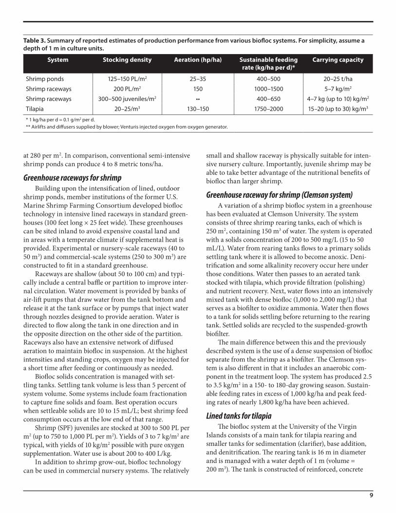
Table 3. Summary of reported estimates of production performance from various biofloc systems. For simplicity, assume a depth of 1 m in culture units.
System Stocking density Aeration (hp/ha) Sustainable feeding rate (kg/ha per d)*
Carrying capacity
Shrimp ponds 125–150 PL/m2 25–35 400–500 20–25 t/ha
Shrimp raceways 200 PL/m2 150 1000–1500 5–7 kg/m2
Shrimp raceways 300–500 juveniles/m2 •• 400–650 4–7 kg (up to 10) kg/m2
Tilapia 20–25/m3 130–150 1750–2000 15–20 (up to 30) kg/m3
* 1 kg/ha per d = 0.1 g/m2 per d.** Airlifts and diffusers supplied by blower; Venturis injected oxygen from oxygen generator.

10
lintel block walls and a 30-mil plastic (HDPE) liner over a smooth earthen tank bottom that slopes slightly (3 per-cent) to a center drain.
Three ¾-hp vertical pump aerators are placed in the tank, with one aerator operated during the first 2 months and then one additional aerator operated during each subsequent 2-month period. Another ¾-hp vertical pump aerator is oriented horizontally and operated continuously for mixing. This aerator establishes a rotational water flow that concentrates solids toward the center drain.
A line from a center drain extends to a 1.9-m3 clari-fier (1 percent of system volume). Water is pumped to the clarifier continuously with a ¼-hp centrifugal pump that provides a flow rate of about 10 gallons per minute. The clarifier is operated with a retention time of 50 minutes, sufficient to settle 90 percent of solids, including all coarse solids and algal floc. Most solids settle readily in 10 min-utes. The full volume of the rearing tank passes through the clarifier every 3 to 4 days. The clarifier can keep sus-pended solids concentration in the rearing tank at about 500 mg/L. Sludge discharged from the bottom cone of the clarifier is directed to a denitrification reactor (50 feet × 4 feet × 3 feet). The denitrification reactor is operated with a flow rate sufficient to give a residence time of 1 day.
Nitrification rates of 3 mg/L per day have been obtained. Nitrate concentration increased with cumulative feed loading, with an accumulation rate of about 25 g/kg feed. Before the denitrification reactor was added, nitrate accumulated to 600 to 700 mg/L (as N) after 6 to 7 months of operation. A nitrogen budget for this system indicated that 45 percent of the nitrogen added in feed was recov-ered as nitrate, 24 percent was in harvested tilapia, and 31 percent was in sludge. Liming (1 to 2 kg/d of quicklime [Ca(OH)2]) is needed to replace the alkalinity lost from acid added by nitrification and to maintain pH at about 7.5.
Sustainable daily feeding rates of 175 to 200 g/m3 (1,750 to 2,000 kg/ha) have been achieved. The maximum standing crop of tilapia is about 15 kg/m3 when fish are stocked at 20 to 25/m3. The working range of conditions for this system include management of solids concentra-tion to 300 to 500 mg/L, equivalent to a settleable solids concentration of 25 to 50 mL/L.
The direct energy requirement per unit of fish pro-duction is about 3.5 to 4 k Wh/kg. Water use efficiency is very high, about 100 L/kg. Replacement water equivalent to 0.2 to 0.4 percent of tank volume was needed to replace daily losses.
ProblemsSuspended solids are central to the function of
biofloc systems. The capacity to control solids concentra-
tion depends on system configuration. Excessive solids concentration is counter-productive because solids can clog gills of fish or shrimp. It also increases the energy required for mixing to keep solids in suspension and aera-tion to meet the oxygen demand of elevated water res-piration. Excessive solids concentration also means that the response time in the event of system failure is very short, often less than 1 hour. Occasionally and unpredict-ably bioflocs will develop that include large numbers of filamentous bacteria. This so-called “filamentous bulking” effect makes flocs slow to settle and makes it difficult to control solids concentration. Filamentous bacteria can also clog shrimp gills and cause mortality.
The microbial ecology of bioflocs is understood at only the most basic level. In particular, the role of biofloc in con-trolling or encouraging pathogenic bacteria, especially Vib-rios, requires further investigation. Vibrios will accumulate in shrimp biofloc systems and can switch on and off their capacity to cause disease. This switching occurs in biofloc systems managed at low or high solids concentrations.
As in most recirculating aquaculture systems, nutri-ents and minerals (especially metals) accumulate in the water of intensively managed biofloc systems. In shrimp raceways with low water exchange rates, nitrate can accumulate to several hundred mg/L, a level that reduces shrimp feed consumption. Including the capacity for denitrification in intensively managed biofloc systems is recommended. In marine systems, maintaining a nitrate concentration of about 50 mg/L is an effective way to minimize the production of highly toxic hydrogen sulfide.
Although research with the forerunners to biofloc systems has been underway since the early 1990s and commercial applications have been in place since the early 2000s, key issues of biofloc system function are still poorly understood. This may be related to the fact that only tilapia and shrimp have been widely cultured in bio-floc systems and that an array of production system con-figurations have been implemented and evaluated. This diversity makes it difficult to establish general principals and design criteria for standard biofloc system configu-rations. This publication discusses the most important variables that must be managed properly to achieve good results.
AcknowledgementInformation for this publication was synthesized and
derived from discussions with, presentations by, and the writings of Yoram Avnimelech, Jim Rakocy, Dave Brune, Jim Ebeling, Craig Browdy, John Leffler, Andrew Ray, Tzachi Samocha, Nyan Taw, Doug Ernst, and Michele Burford.
11
Recommended literatureAvnimelech, Y. (ed.). 2009. Biofloc Technology, Second
Edition. World Aquaculture Society, Baton Rouge, LA.Burford, M.A., P.J. Thompson, R.P. McIntosh, R.H. Bau-
man, and D.C. Pearson. 2003. Nutrient and microbial dynamics in high-intensity, zero-exchange shrimp ponds in Belize. Aquaculture 219:393-411.
DeSchryver, P., R. Crab, T. Defroit, N. Boon, and W. Verstraete. 2008. The basics of biofloc technology: the added value for aquaculture. Aquaculture 277:125-137.
Ebeling, J.M., M.B. Timmons, and J.J. Bisogni. 2006. Engineering analysis of the stoichiometry of photoau-totrophic, autotrophic, and heterotrophic removal of ammonia-nitrogen in aquaculture systems. Aquacul-ture 257:346-358.
Hargreaves, J.A. 2006. Photosynthetic suspended growth systems in aquaculture. Aquacultural Engineering 34:344-363.
Ray, A.J., A.J. Shuler, J.W. Leffler, and C.L Browdy. 2009. Microbial ecology and management of biofloc sys-tems. pp. 255-266 in: C.L. Browdy and D.E. Jory (eds.). The Rising Tide: Proceedings of the Special Session on Sustainable Shrimp Farming. World Aquaculture Society, Baton Rouge, LA.
Organization and internet websiteBiofloc Workgroup of the Aquacultural Engineering
Society (www.aesweb.org).
12
The views expressed in this publication are those of the authors and do not necessarily reflect those of USDA or any of its subagencies. Trade names are used for descriptive purposes only and their use does not imply endorsement by USDA, SRAC, the authors, or their employers and does not imply approval to the exclusion of other products that may also be suitable.
SRAC fact sheets are reviewed annually by the Publications, Videos and Computer Software Steering Committee. Fact sheets are revised as new knowledge becomes available. Fact sheets that have not been revised are considered to reflect the current state of knowledge.
The work reported in this publication was supported in part by the Southern Regional Aquaculture Center through Grant No. 2008-38500-19251 from the United States Department of Agriculture, National Institute of Food and Agriculture.