vhdl and sequential circuit synthesis vhdl constructs versus automatic synthesis what is synthesis?...
Post on 19-Dec-2015
269 views
TRANSCRIPT
VHDL and Sequential VHDL and Sequential circuit Synthesiscircuit Synthesis
• VHDL constructs versus automatic synthesis
• What is synthesis?
• Building blocks
• Issues and example
• Tools and targets
Hardware Description Hardware Description Language (HDL)Language (HDL)
• Describe hardware – not software
• Description – structure
• Language – strong syntax and type declarations
• Start with a block diagram
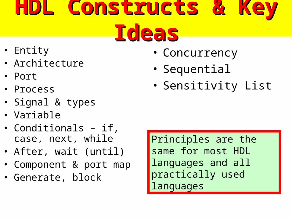
HDL Constructs & Key IdeasHDL Constructs & Key Ideas• Entity• Architecture• Port• Process• Signal & types• Variable• Conditionals – if, case, next,
while• After, wait (until)• Component & port map• Generate, block
• Concurrency• Sequential• Sensitivity List
Principles are the same for most HDL languages and all practically used languages
Multiple Architectures for the same Multiple Architectures for the same entityentity
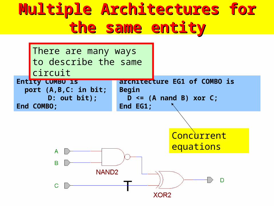
Entity COMBO is port (A,B,C: in bit;
D: out bit);End COMBO;
architecture EG1 of COMBO isBegin D <= (A nand B) xor C;End EG1;
There are many ways to describe the same circuit
Concurrent equations
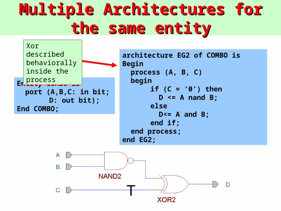
Entity COMBO is port (A,B,C: in bit;
D: out bit);End COMBO;
architecture EG2 of COMBO isBegin process (A, B, C) begin
if (C = ‘0’) then D <= A nand B;else D<= A and B;end if;
end process;end EG2;
Xor described behaviorally inside the process
Multiple Architectures for the same Multiple Architectures for the same entityentity

Entity COMBO is port (A,B,C: in bit;
D: out bit);End COMBO;
architecture EG3 of COMBO is signal T : bit;begin T <= A nand B; p1 : process (T,C) begin D <= T xor C; end process p1;end EG3;
Mix concurrent statements and processes
Multiple Architectures for the same Multiple Architectures for the same entityentity
As we see, even for a very small circuit there are several descriptions possible. In case of large sequential systems, this number is extremely large, how to select best? How to program in such a way that the system will generate the best?
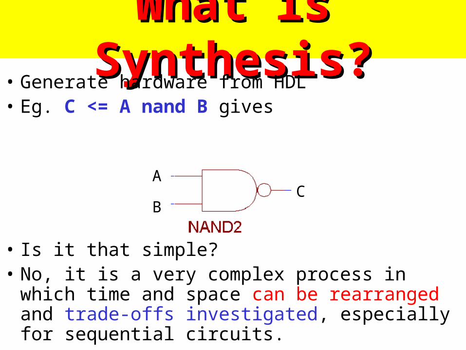
What is Synthesis?What is Synthesis?• Generate hardware from HDL• Eg. C <= A nand B gives
• Is it that simple?• No, it is a very complex process in which time and
space can be rearranged and trade-offs investigated, especially for sequential circuits.
A
BC
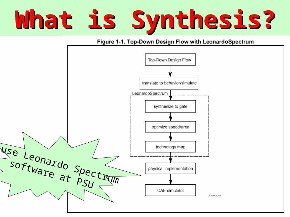
What is Synthesis?What is Synthesis?
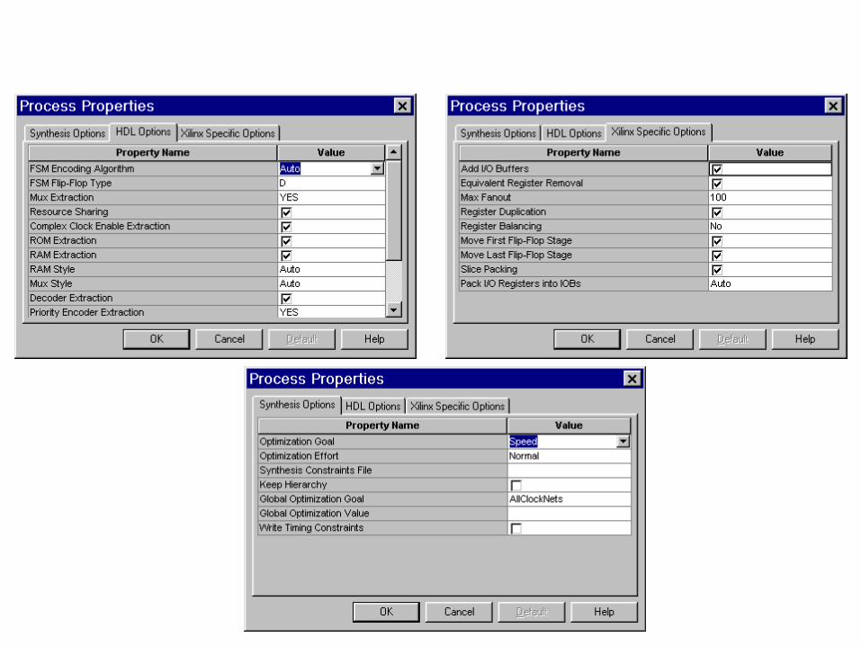
We use Leonardo Spectrum software at PSU
Watch out for these statements!Watch out for these statements!
• Time expressions – after
• Assert, Text I/O
• Configuration declarations
• Dynamic Loops
• Initial values
• Sensitivity lists
Simulation purposeSimulation purpose
Affect synthesized structures
Basic Sequential elementsBasic Sequential elements• LatchesLatches
– Cheaper than FFs
– Troubles with timing analysis and synchronization
– Possible implication of undesired latches when you assign improper modeling type
• Flip-flopsFlip-flops
– Edge sensitive
– Asynchronous and synchronous set and reset
Descriptions 4s5ng Descriptions 4s5ng 3atches3atches
• You have to distinguish between combinational, latches and synchronized Flip-Flops
• Lack of understanding is a common source of errors.common source of errors.
• We will first cover latches,
• Next we will cover flip-flops
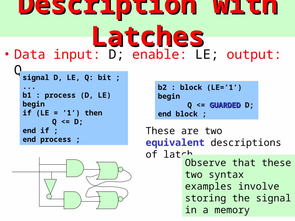
Description with LatchesDescription with Latches• Data input: D; enable: LE; output: Q.
signal D, LE, Q: bit ;...b1 : process (D, LE)beginif (LE = ’1’) then
Q <= D;end if ;end process ;
b2 : block (LE=’1’)begin
Q <= GUARDEDGUARDED D;end block ;
These are two equivalent descriptions of latch
Observe that these two syntax examples involve storing the signal in a memory
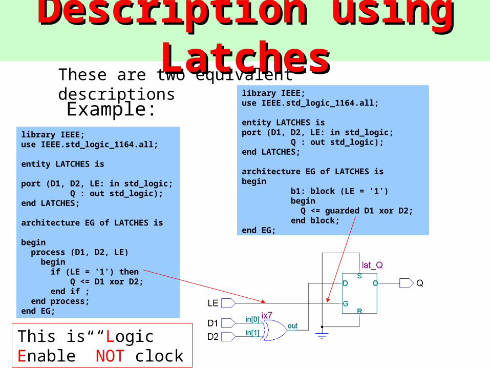
Description using LatchesDescription using Latcheslibrary IEEE;use IEEE.std_logic_1164.all;
entity LATCHES isport (D1, D2, LE: in std_logic;
Q : out std_logic);end LATCHES;
architecture EG of LATCHES isbegin
b1: block (LE = '1')begin Q <= guarded D1 xor D2;end block;
end EG;
library IEEE;use IEEE.std_logic_1164.all;
entity LATCHES is
port (D1, D2, LE: in std_logic;Q : out std_logic);
end LATCHES;
architecture EG of LATCHES is
begin process (D1, D2, LE) begin if (LE = '1') then
Q <= D1 xor D2; end if ; end process;end EG;
Example:
This is “Logic Enable” NOT clock
These are two equivalent descriptions
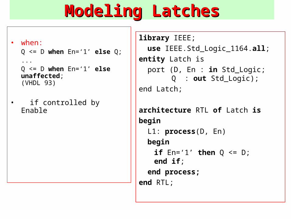
ModelModeling Latchesing Latches
• when:Q <= D when En=‘1’ else Q;...Q <= D when En=‘1’ else unaffected;(VHDL 93)
• if controlled by Enable
library IEEE;
use IEEE.Std_Logic_1164.all;
entity Latch is
port (D, En : in Std_Logic; Q : out Std_Logic);
end Latch;
architecture RTL of Latch is
begin
L1: process(D, En)
begin
if En=‘1’ then Q <= D; end if;
end process;
end RTL;
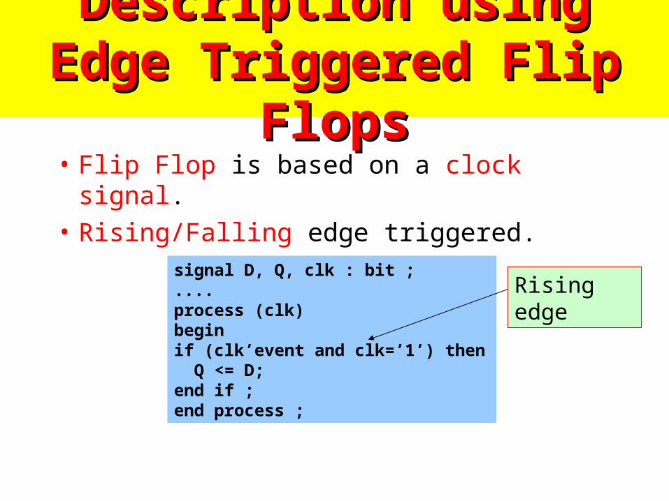
Description using Edge Description using Edge Triggered Flip FlopsTriggered Flip Flops
• Flip Flop is based on a clock signal.
• Rising/Falling edge triggered.
signal D, Q, clk : bit ;....process (clk)beginif (clk’event and clk=’1’) then Q <= D;end if ;end process ;
Rising edge
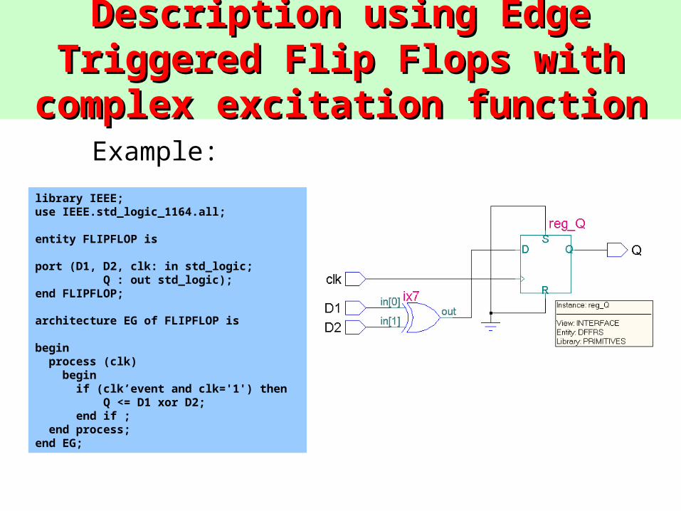
Description using Edge Triggered Flip Description using Edge Triggered Flip Flops with complex excitation functionFlops with complex excitation function
library IEEE;use IEEE.std_logic_1164.all;
entity FLIPFLOP is
port (D1, D2, clk: in std_logic;Q : out std_logic);
end FLIPFLOP;
architecture EG of FLIPFLOP is
begin process (clk) begin if (clk’event and clk='1') then
Q <= D1 xor D2; end if ; end process;end EG;
Example:
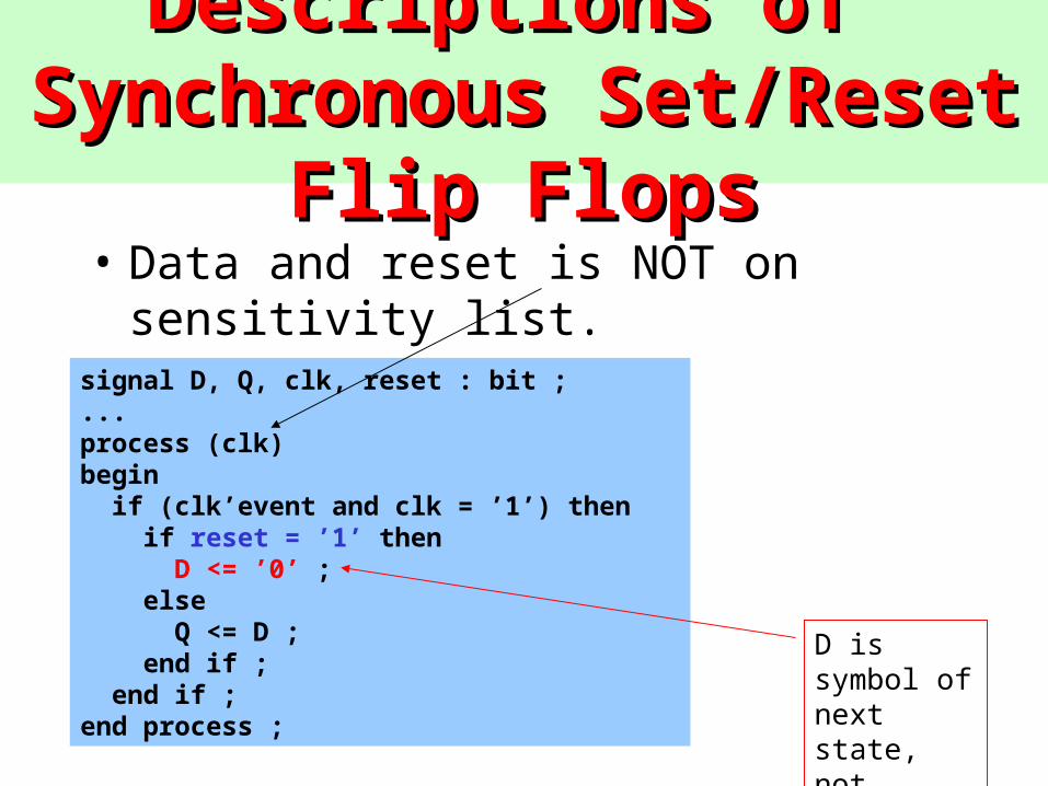
Descriptions of Synchronous Descriptions of Synchronous Set/Reset Flip FlopsSet/Reset Flip Flops
• Data and reset is NOT on sensitivity list.
signal D, Q, clk, reset : bit ;...process (clk)begin if (clk’event and clk = ’1’) then if reset = ’1’ then D <= ’0’ ; else Q <= D ; end if ; end if ;end process ;
D is symbol of next state, not current state
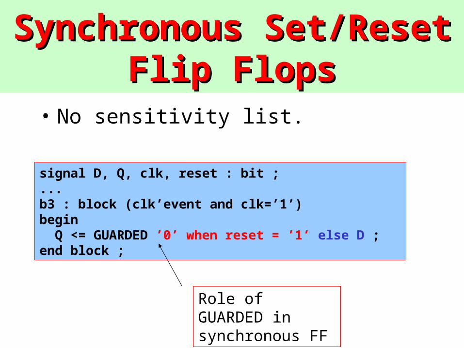
Synchronous Set/Reset Flip Synchronous Set/Reset Flip FlopsFlops
• No sensitivity list.
signal D, Q, clk, reset : bit ;...b3 : block (clk’event and clk=’1’)begin Q <= GUARDED ’0’ when reset = ’1’ else D ;end block ;
Role of GUARDED in synchronous FF
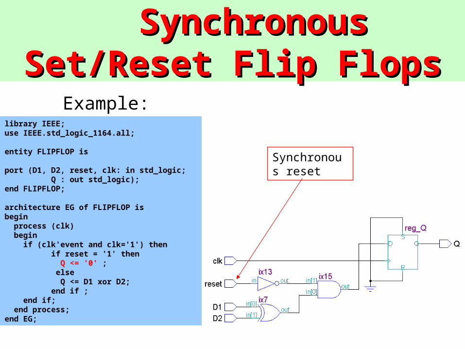
Synchronous Set/Reset Flip Synchronous Set/Reset Flip FlopsFlops
library IEEE;use IEEE.std_logic_1164.all;
entity FLIPFLOP is
port (D1, D2, reset, clk: in std_logic;Q : out std_logic);
end FLIPFLOP;
architecture EG of FLIPFLOP isbegin process (clk) begin if (clk'event and clk='1') then
if reset = '1' then Q <= '0' ; else Q <= D1 xor D2; end if ; end if; end process;end EG;
Example:
Synchronous reset
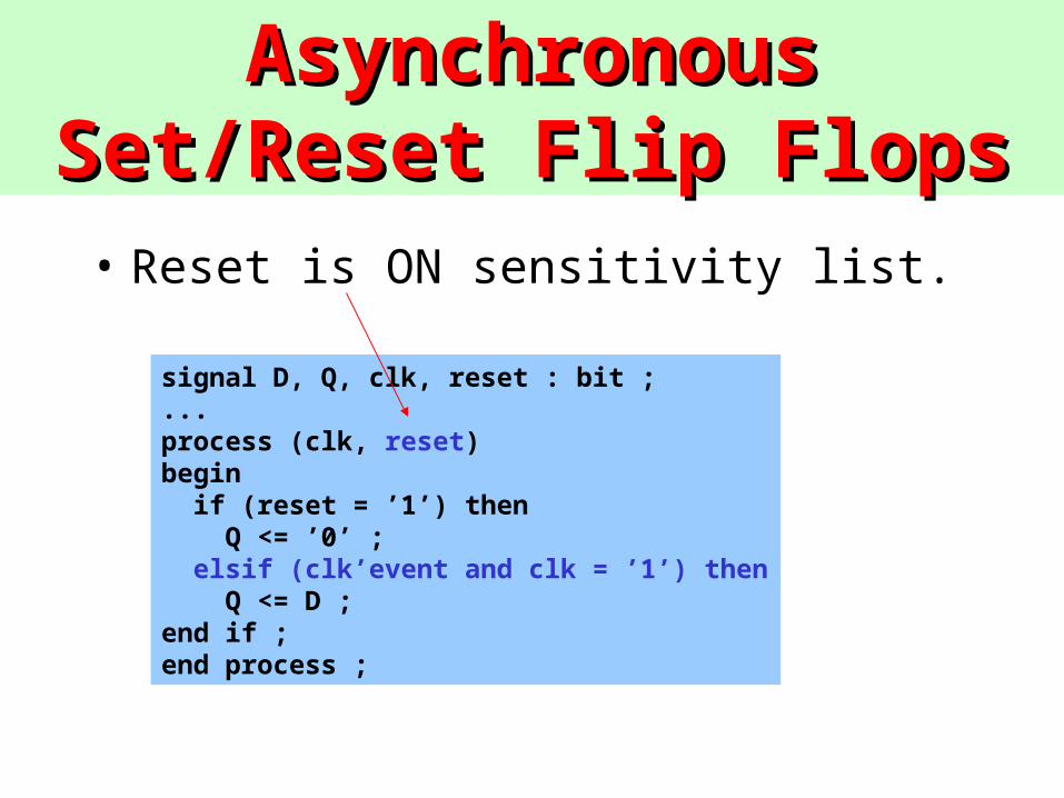
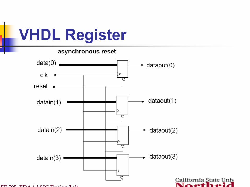
Asynchronous Set/Reset Flip Asynchronous Set/Reset Flip FlopsFlops
• Reset is ON sensitivity list.
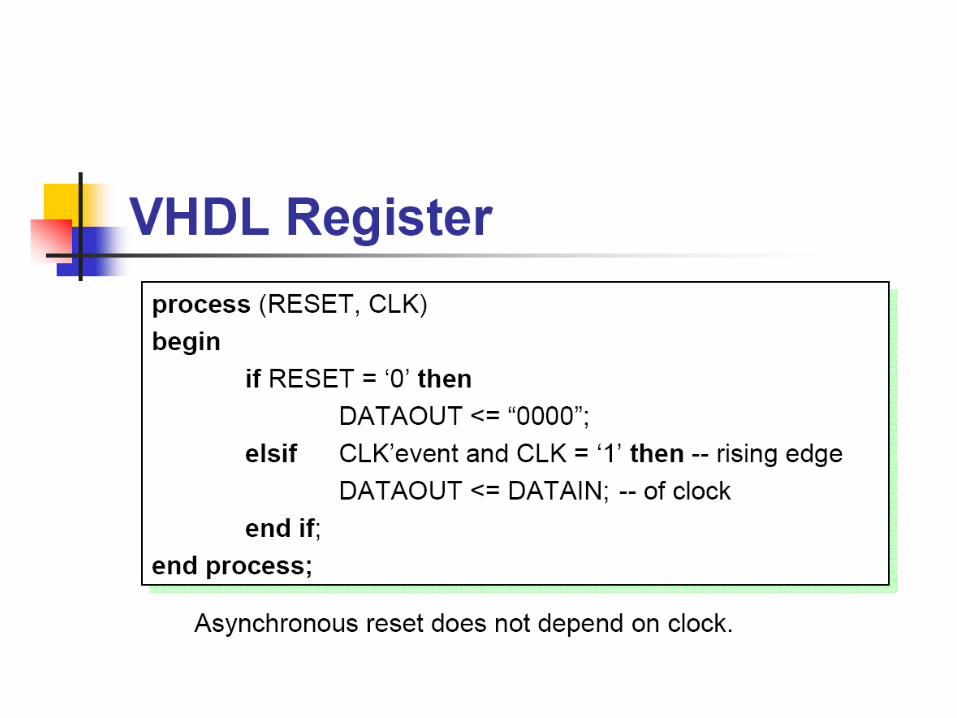
signal D, Q, clk, reset : bit ;...process (clk, reset)begin if (reset = ’1’) then Q <= ’0’ ; elsif (clk’event and clk = ’1’) then Q <= D ;end if ;end process ;
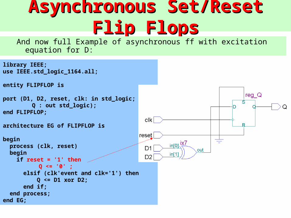
Asynchronous Set/Reset Flip FlopsAsynchronous Set/Reset Flip Flops
library IEEE;use IEEE.std_logic_1164.all;
entity FLIPFLOP is
port (D1, D2, reset, clk: in std_logic;Q : out std_logic);
end FLIPFLOP;
architecture EG of FLIPFLOP is
begin process (clk, reset) begin if reset = '1' then Q <= '0' ; elsif (clk'event and clk='1') then Q <= D1 xor D2; end if; end process;end EG;
And now full Example of asynchronous ff with excitation equation for D:
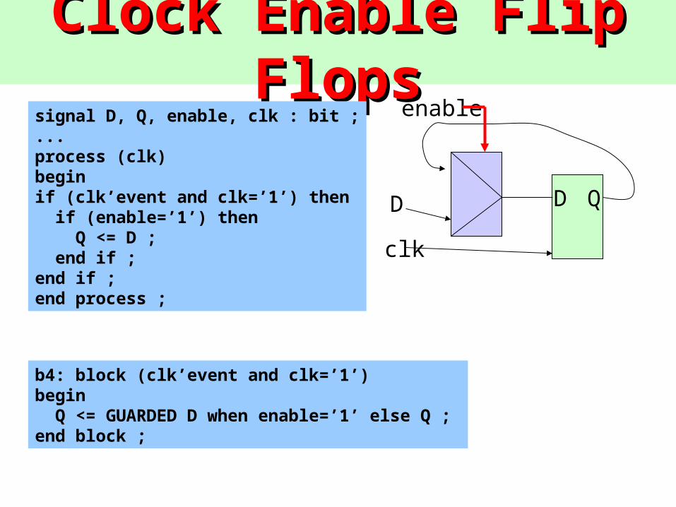
Clock Enable Flip FlopsClock Enable Flip Flopssignal D, Q, enable, clk : bit ;...process (clk)beginif (clk’event and clk=’1’) then if (enable=’1’) then Q <= D ; end if ;end if ;end process ;
b4: block (clk’event and clk=’1’)begin Q <= GUARDED D when enable=’1’ else Q ;end block ;
D Q
clk
enable
D
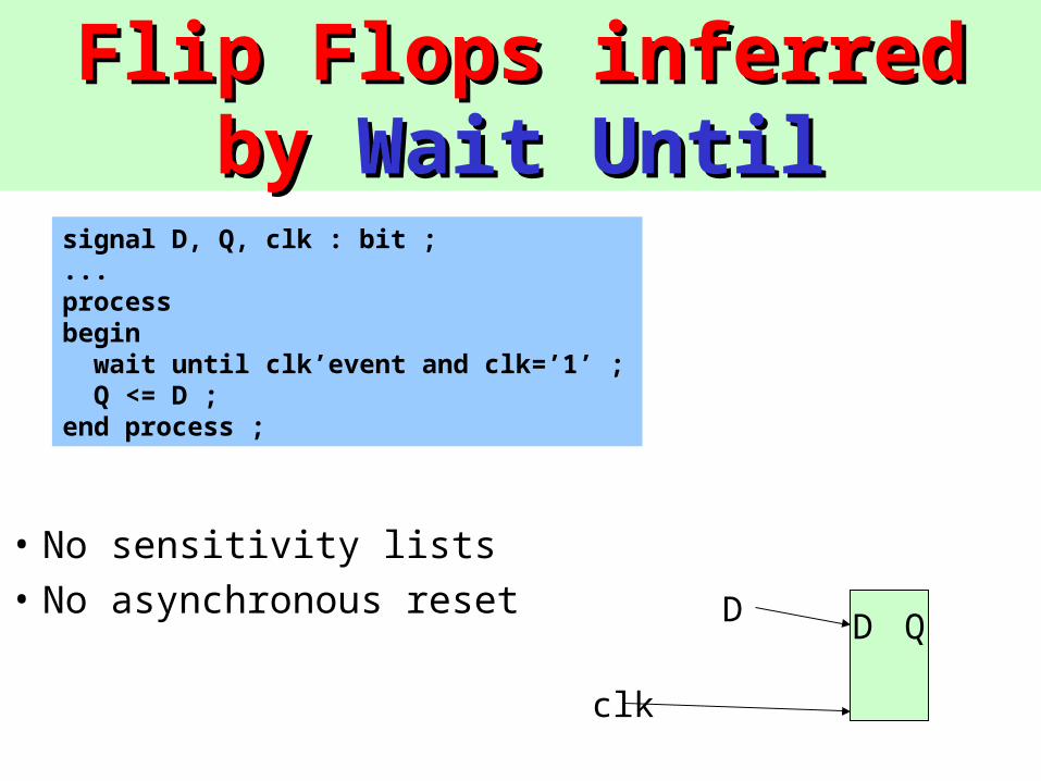
Flip Flops inferred by Flip Flops inferred by Wait Wait UntilUntil
signal D, Q, clk : bit ;...processbegin wait until clk’event and clk=’1’ ; Q <= D ;end process ;
• No sensitivity lists
• No asynchronous reset D Q
clk
D
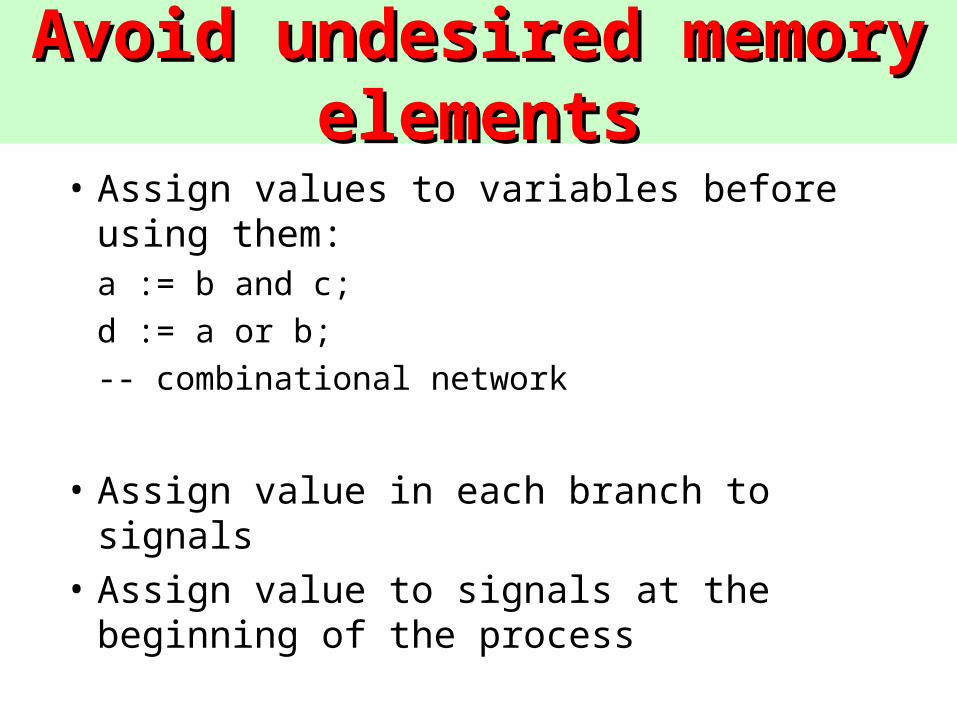
Avoid undesired memory Avoid undesired memory elementselements
• Assign values to variables before using them:a := b and c;
d := a or b;
-- combinational network
• Assign value in each branch to signals
• Assign value to signals at the beginning of the process
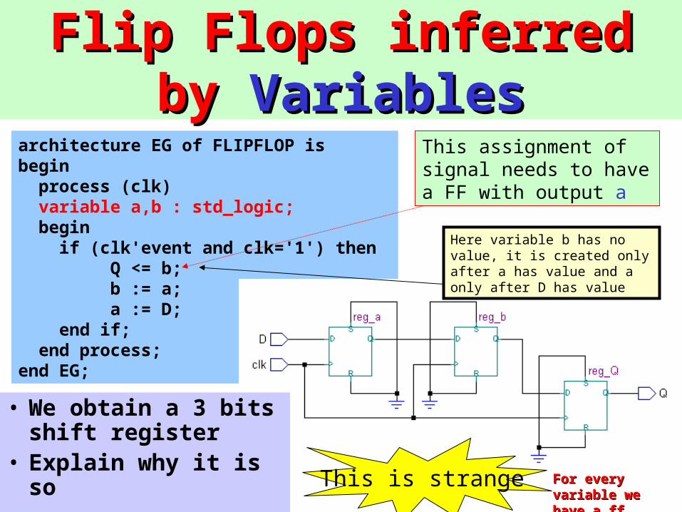
Flip Flops inferred by Flip Flops inferred by VariablesVariables
architecture EG of FLIPFLOP isbegin process (clk) variable a,b : std_logic; begin if (clk'event and clk='1') then Q <= b; b := a; a := D; end if; end process;end EG;
This assignment of signal needs to have a FF with output a
This is strange
• We obtain a 3 bits shift register
• Explain why it is so For every variable For every variable we have a ff.we have a ff.
Here variable b has no value, it is created only after a has value and a only after D has value
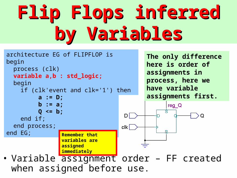
Flip Flops inferred by Flip Flops inferred by VariablesVariables
• Variable assignment order – FF created when assigned before use.
architecture EG of FLIPFLOP isbegin process (clk) variable a,b : std_logic; begin if (clk'event and clk='1') then a := D; b := a; Q <= b; end if; end process;end EG;
The only difference here is order of assignments in process, here we have variable assignments first.
Remember that variables are assigned immediately
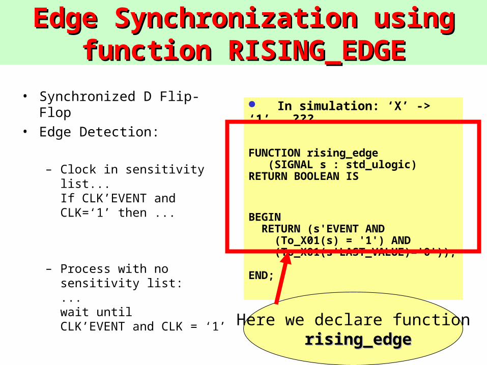
Edge Synchronization using function Edge Synchronization using function RISING_EDGERISING_EDGE
• Synchronized D Flip-Flop
• Edge Detection:
– Clock in sensitivity list...If CLK’EVENT and CLK=‘1’ then ...
– Process with no sensitivity list:...wait until CLK’EVENT and CLK = ‘1’
In simulation: ‘X’ -> ‘1’ ???
FUNCTION rising_edge (SIGNAL s : std_ulogic) RETURN BOOLEAN IS
BEGIN RETURN (s'EVENT AND (To_X01(s) = '1') AND (To_X01(s'LAST_VALUE)='0')); END;
Here we declare function rising_edgerising_edge
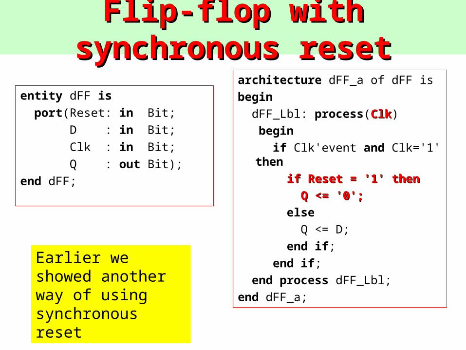
Flip-flop with synchronous resetFlip-flop with synchronous reset
entity dFF is port(Reset: in Bit; D : in Bit; Clk : in Bit; Q : out Bit);end dFF;
architecture dFF_a of dFF is begin dFF_Lbl: process(ClkClk) begin if Clk'event and Clk='1'
then if Reset = '1' then if Reset = '1' then
Q <= '0';Q <= '0'; else Q <= D; end if; end if; end process dFF_Lbl; end dFF_a;
Earlier we showed another way of using synchronous reset
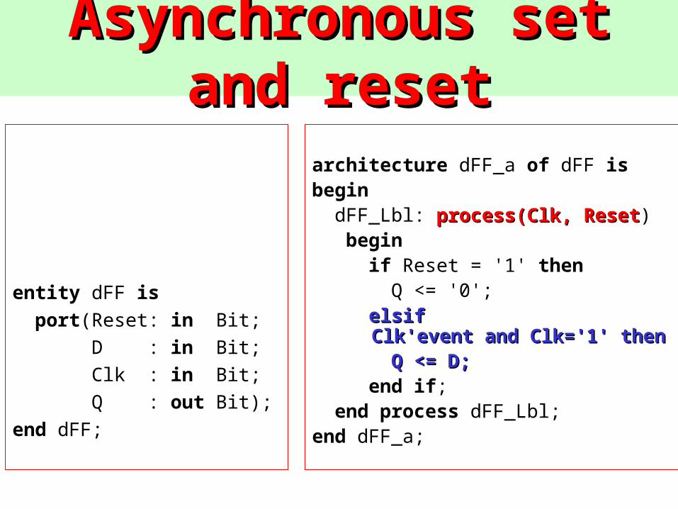
AsynchronAsynchronous set and resetous set and reset
entity dFF is port(Reset: in Bit; D : in Bit; Clk : in Bit; Q : out Bit);end dFF;
architecture dFF_a of dFF is begin dFF_Lbl: process(Clk, Resetprocess(Clk, Reset) begin if Reset = '1' then Q <= '0'; elsif elsif
Clk'event and Clk='1' then Clk'event and Clk='1' then Q <= D;Q <= D; end if; end process dFF_Lbl; end dFF_a;
Why so many FF syntax?Why so many FF syntax?• Highlight the importance of writing good HDL code
• Coding style affects synthesized structure directly
• Internal working of synthesizers
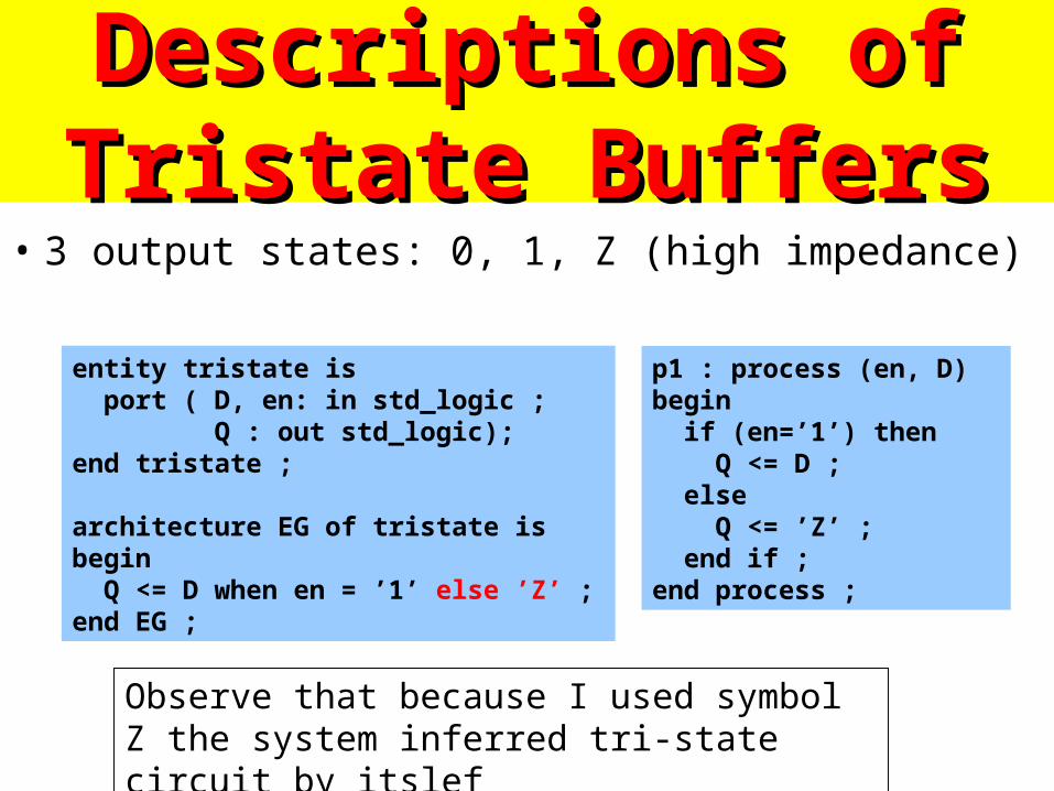
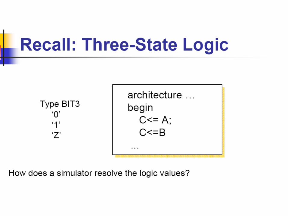
Descriptions of Tristate Descriptions of Tristate BuffersBuffers
• 3 output states: 0, 1, Z (high impedance)
entity tristate is port ( D, en: in std_logic ; Q : out std_logic);end tristate ;
architecture EG of tristate isbegin Q <= D when en = ’1’ else ’Z’ ;end EG ;
p1 : process (en, D) begin if (en=’1’) then Q <= D ; else Q <= ’Z’ ; end if ;end process ;
Observe that because I used symbol Z the system inferred tri-state circuit by itslef
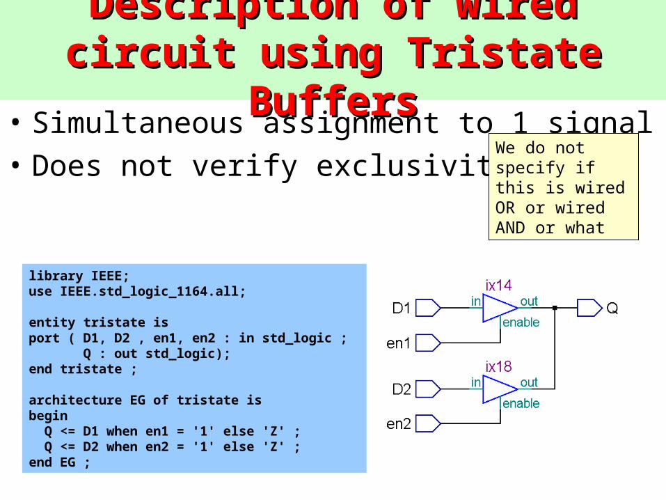
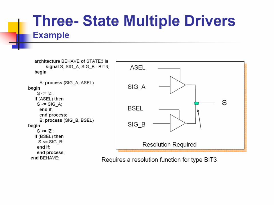
Description of wired circuit using Description of wired circuit using Tristate BuffersTristate Buffers
• Simultaneous assignment to 1 signal
• Does not verify exclusivity
library IEEE;use IEEE.std_logic_1164.all;
entity tristate isport ( D1, D2 , en1, en2 : in std_logic ; Q : out std_logic);end tristate ;
architecture EG of tristate isbegin Q <= D1 when en1 = '1' else 'Z' ; Q <= D2 when en2 = '1' else 'Z' ;end EG ;
We do not specify if this is wired OR or wired AND or what
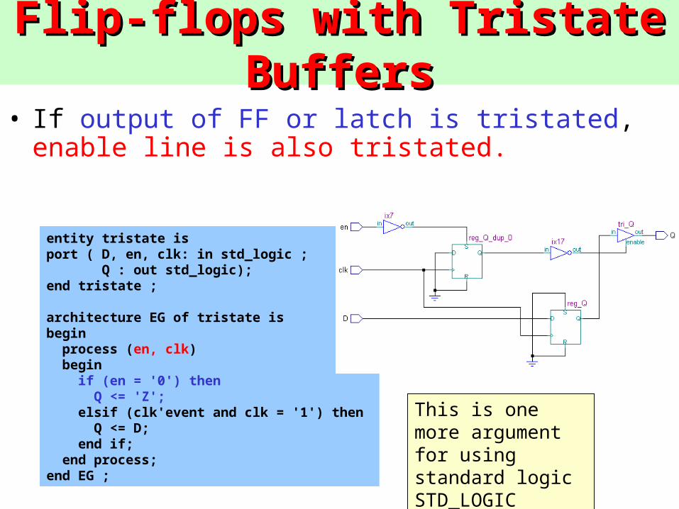
Flip-flops with Tristate BuffersFlip-flops with Tristate Buffers
• If output of FF or latch is tristated, enable line is also tristated.
entity tristate isport ( D, en, clk: in std_logic ; Q : out std_logic);end tristate ;
architecture EG of tristate isbegin process (en, clk) begin if (en = '0') then Q <= 'Z'; elsif (clk'event and clk = '1') then Q <= D; end if; end process;end EG ;
This is one more argument for using standard logic STD_LOGIC
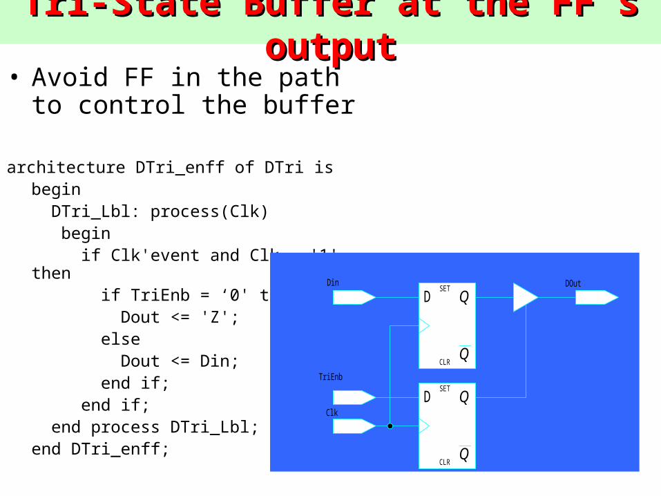
Tri-State Buffer at the FF’s outputTri-State Buffer at the FF’s output• Avoid FF in the path to control
the buffer
architecture DTri_enff of DTri is begin DTri_Lbl: process(Clk) begin if Clk'event and Clk = '1' then if TriEnb = ‘0' then Dout <= 'Z'; else Dout <= Din; end if; end if; end process DTri_Lbl; end DTri_enff;
D
Q
QSET
CLR
D
Q
QSET
CLR
Din
TriEnb
Clk
DOut
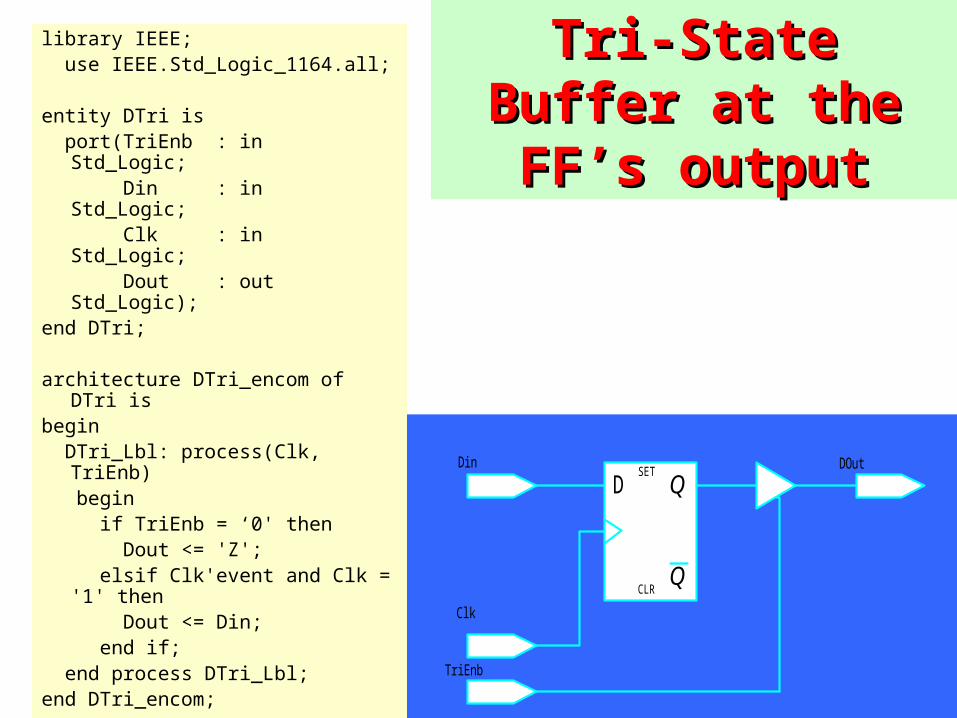
Tri-State Buffer at Tri-State Buffer at the FF’s outputthe FF’s output
D
Q
QSET
CLR
Din
Clk
TriEnb
DOut
library IEEE; use IEEE.Std_Logic_1164.all;
entity DTri is port(TriEnb : in Std_Logic; Din : in Std_Logic; Clk : in Std_Logic; Dout : out Std_Logic);end DTri;
architecture DTri_encom of DTri is begin DTri_Lbl: process(Clk, TriEnb) begin if TriEnb = ‘0' then Dout <= 'Z'; elsif Clk'event and Clk = '1' then Dout <= Din; end if; end process DTri_Lbl; end DTri_encom;
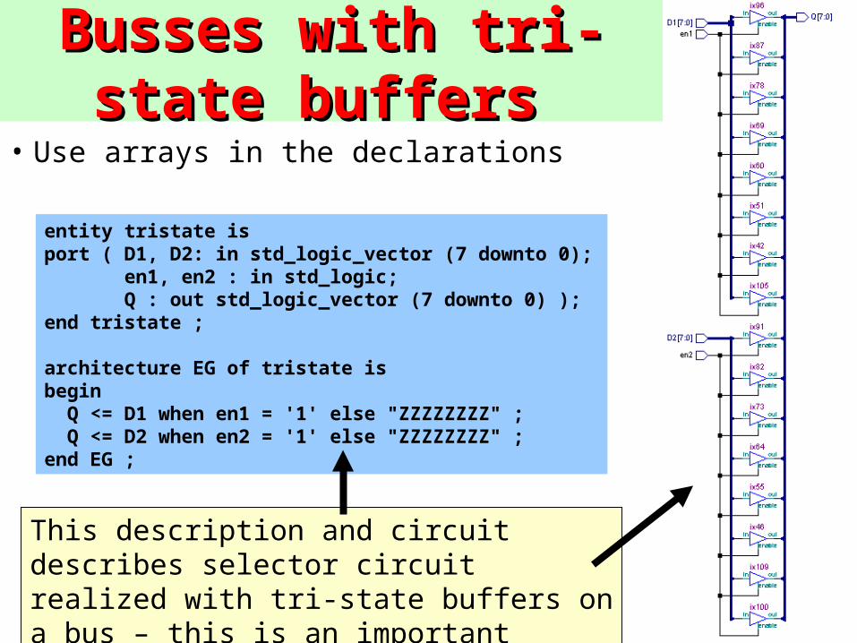
Busses with tri-state Busses with tri-state buffers buffers
entity tristate isport ( D1, D2: in std_logic_vector (7 downto 0); en1, en2 : in std_logic; Q : out std_logic_vector (7 downto 0) );end tristate ;
architecture EG of tristate isbegin Q <= D1 when en1 = '1' else "ZZZZZZZZ" ; Q <= D2 when en2 = '1' else "ZZZZZZZZ" ;end EG ;
• Use arrays in the declarations
This description and circuit describes selector circuit realized with tri-state buffers on a bus – this is an important circuit
State MachinesState Machinesstart foundwait
1
0 1
0
0
1
0 0 1
start start wait found start
clk
sig
result
state
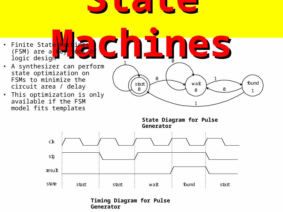
• Finite State Machines (FSM) are a key tool of logic design
• A synthesizer can perform state optimization on FSMs to minimize the circuit area / delay
• This optimization is only available if the FSM model fits templates
State Diagram for Pulse Generator
Timing Diagram for Pulse Generator
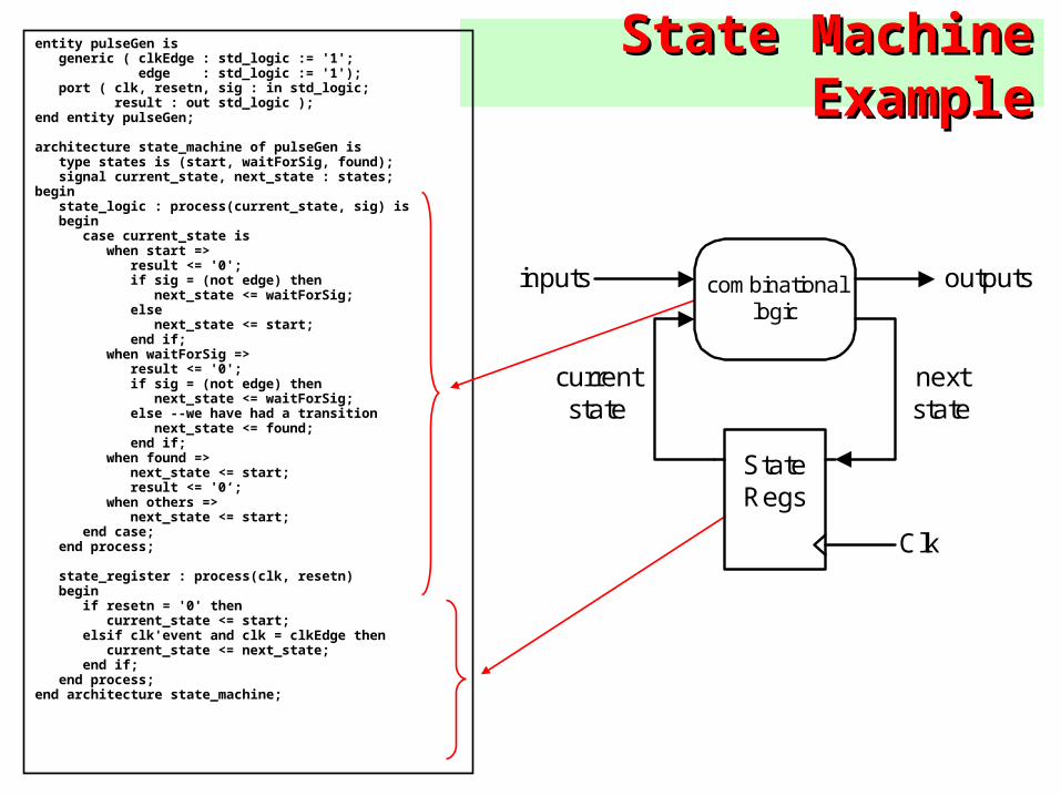
State Machine ExampleState Machine Exampleentity pulseGen is generic ( clkEdge : std_logic := '1'; edge : std_logic := '1'); port ( clk, resetn, sig : in std_logic; result : out std_logic );end entity pulseGen;
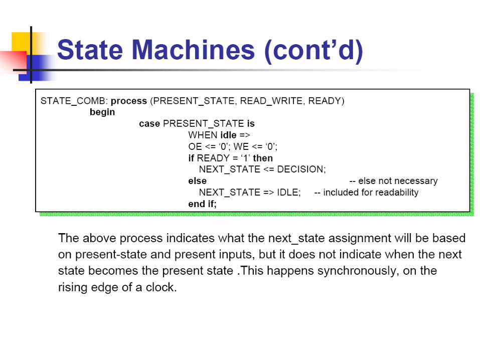
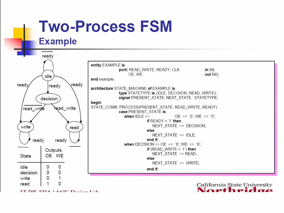
architecture state_machine of pulseGen is type states is (start, waitForSig, found); signal current_state, next_state : states;begin state_logic : process(current_state, sig) is begin case current_state is when start => result <= '0'; if sig = (not edge) then next_state <= waitForSig; else next_state <= start; end if; when waitForSig => result <= '0'; if sig = (not edge) then next_state <= waitForSig; else --we have had a transition next_state <= found; end if; when found => next_state <= start; result <= '0‘; when others => next_state <= start; end case; end process;
state_register : process(clk, resetn) begin if resetn = '0' then current_state <= start; elsif clk'event and clk = clkEdge then current_state <= next_state; end if; end process;end architecture state_machine;
Clk
StateRegs
combinationallogic
inputs outputs
currentstate
nextstate
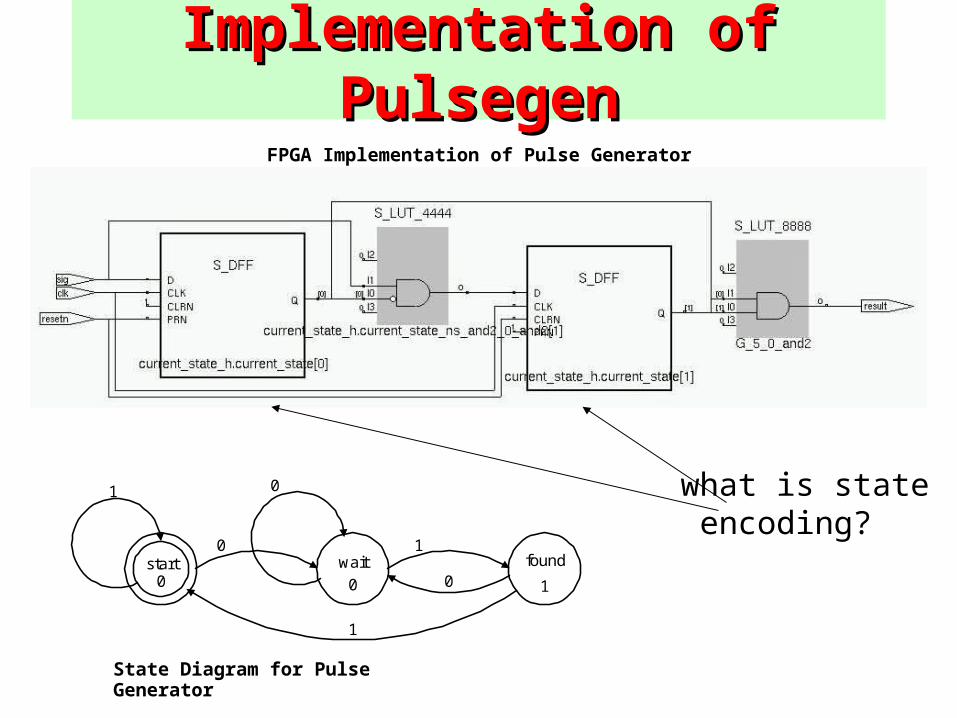
Implementation of PulsegenImplementation of Pulsegen
start foundwait
1
0 1
0
0
1
0 0 1
State Diagram for Pulse Generator
FPGA Implementation of Pulse Generator
what is state encoding?
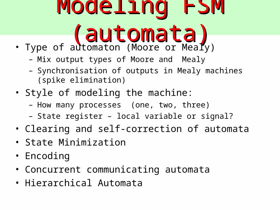
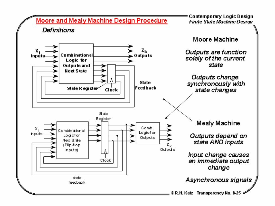
ModelModeling FSM (automata)ing FSM (automata)• Type of automaton (Moore or Mealy)
– Mix output types of Moore and Mealy
– Synchronisation of outputs in Mealy machines (spike elimination)
• Style of modeling the machine: – How many processes (one, two, three)
– State register – local variable or signal?
• Clearing and self-correction of automata
• State Minimization
• Encoding
• Concurrent communicating automata
• Hierarchical Automata
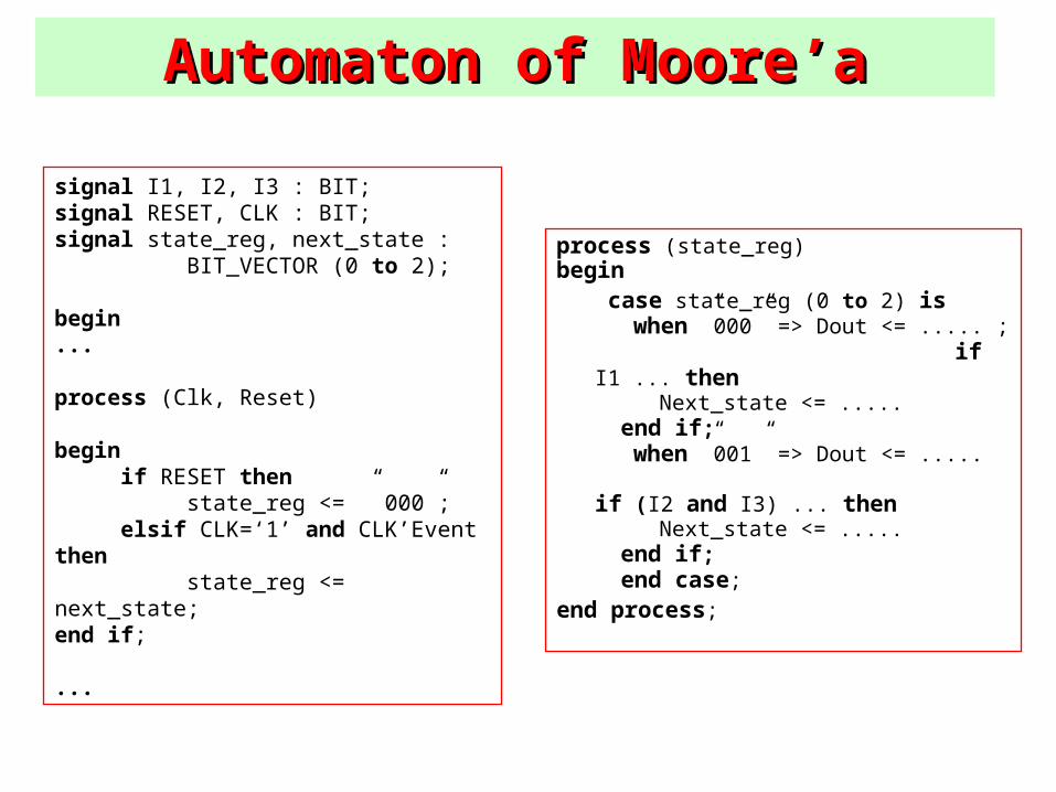
AutomatAutomaton ofon of Moore’a Moore’a
signal I1, I2, I3 : BIT;signal RESET, CLK : BIT;signal state_reg, next_state : BIT_VECTOR (0 to 2);
begin...
process (Clk, Reset)
begin if RESET then state_reg <= ” 000”; elsif CLK=‘1’ and CLK’Event then state_reg <= next_state;end if;
...
process (state_reg)begin case state_reg (0 to 2) is
when ”000” => Dout <= ..... ; if I1 ... then
Next_state <= ..... end if;
when ”001” => Dout <= ..... if (I2 and I3) ... then
Next_state <= ..... end if;
end case;
end process;
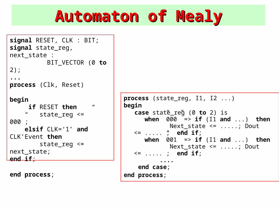
AutomatAutomaton ofon of Mealy Mealysignal RESET, CLK : BIT;signal state_reg, next_state : BIT_VECTOR (0 to 2);...process (Clk, Reset)
begin if RESET then state_reg <= ” 000”; elsif CLK=‘1’ and CLK’Event then
state_reg <= next_state;end if;
end process;
process (state_reg, I1, I2 ...)begin case state_reg (0 to 2) is
when ”000” => if (I1 and ...) then Next_state <= .....; Dout <= ..... ; end if; when ”001” => if (I1 and ...) then Next_state <= .....; Dout <= ..... ; end if;
.... end case;end process;
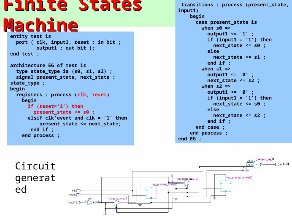
Finite States MachineFinite States Machineentity test is port ( clk, input1, reset : in bit ; output1 : out bit );end test ;
architecture EG of test is type state_type is (s0, s1, s2) ; signal present_state, next_state : state_type ;begin registers : process (clk, reset) begin if (reset='1') then present_state <= s0 ; elsif clk'event and clk = '1' then present_state <= next_state; end if ; end process ;
transitions : process (present_state, input1) begin case present_state is when s0 => output1 <= '1' ; if (input1 = '1') then next_state <= s0 ; else next_state <= s1 ; end if ; when s1 => output1 <= '0' ; next_state <= s2 ; when s2 => output1 <= '0' ; if (input1 = '1') then next_state <= s0 ; else next_state <= s2 ; end if ; end case ; end process ;end EG ;
Circuit generated
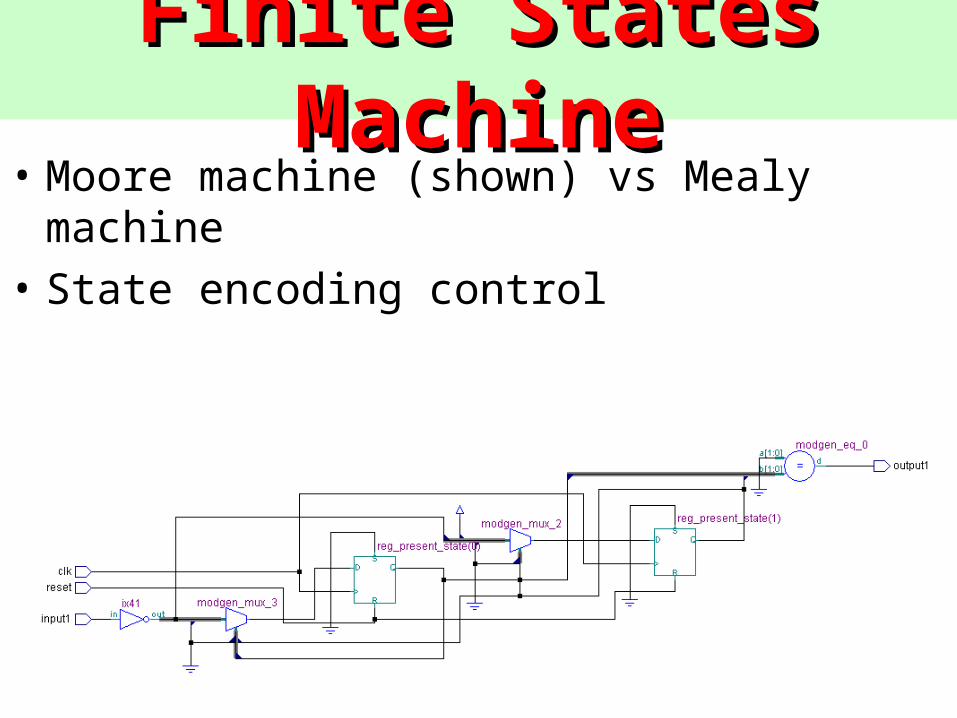
Finite States MachineFinite States Machine• Moore machine (shown) vs Mealy machine
• State encoding control
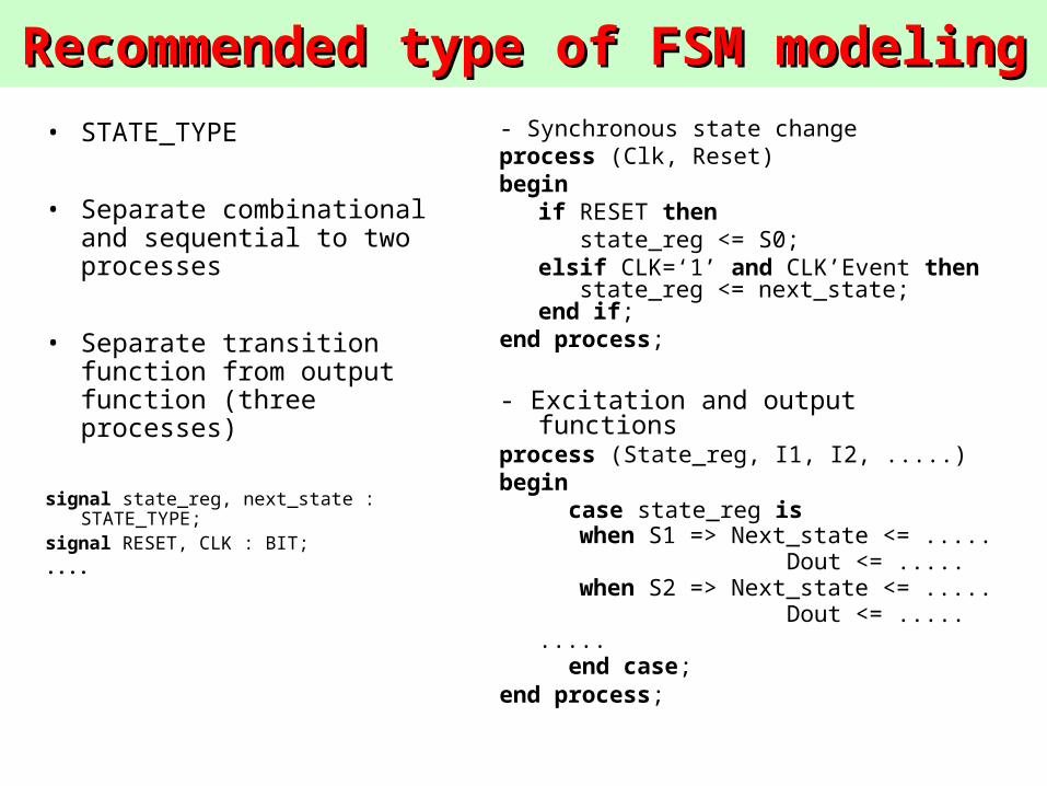
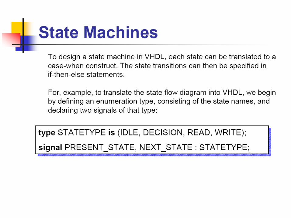
ReReccomommmendended type of FSM modelinged type of FSM modeling
• STATE_TYPE
• Separate combinational and sequential to two processes
• Separate transition function from output function (three processes)
signal state_reg, next_state : STATE_TYPE;
signal RESET, CLK : BIT;....
- Synchronous state changeprocess (Clk, Reset)begin
if RESET then state_reg <= S0;elsif CLK=‘1’ and CLK’Event then state_reg <= next_state;end if;
end process;
- Excitation and output functionsprocess (State_reg, I1, I2, .....)begin case state_reg is
when S1 => Next_state <= ..... Dout <= .....
when S2 => Next_state <= ..... Dout <= .....
..... end case;end process;
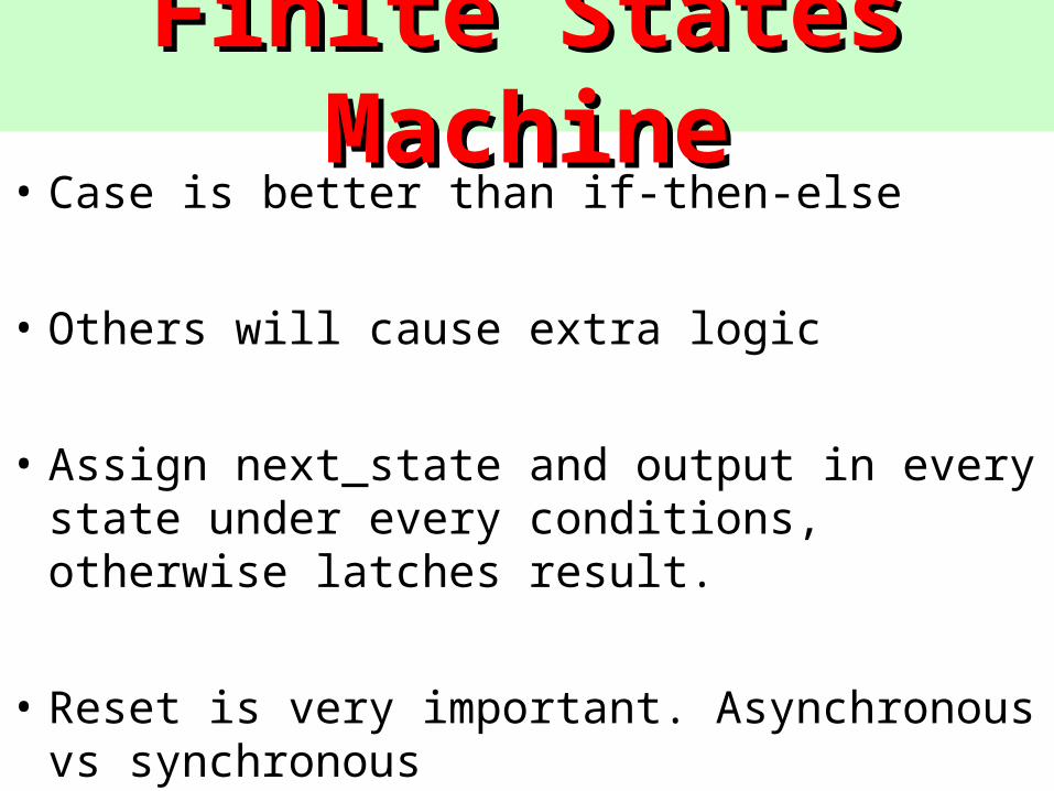
Finite States MachineFinite States Machine• Case is better than if-then-else
• Others will cause extra logic
• Assign next_state and output in every state under every conditions, otherwise latches result.
• Reset is very important. Asynchronous vs synchronous
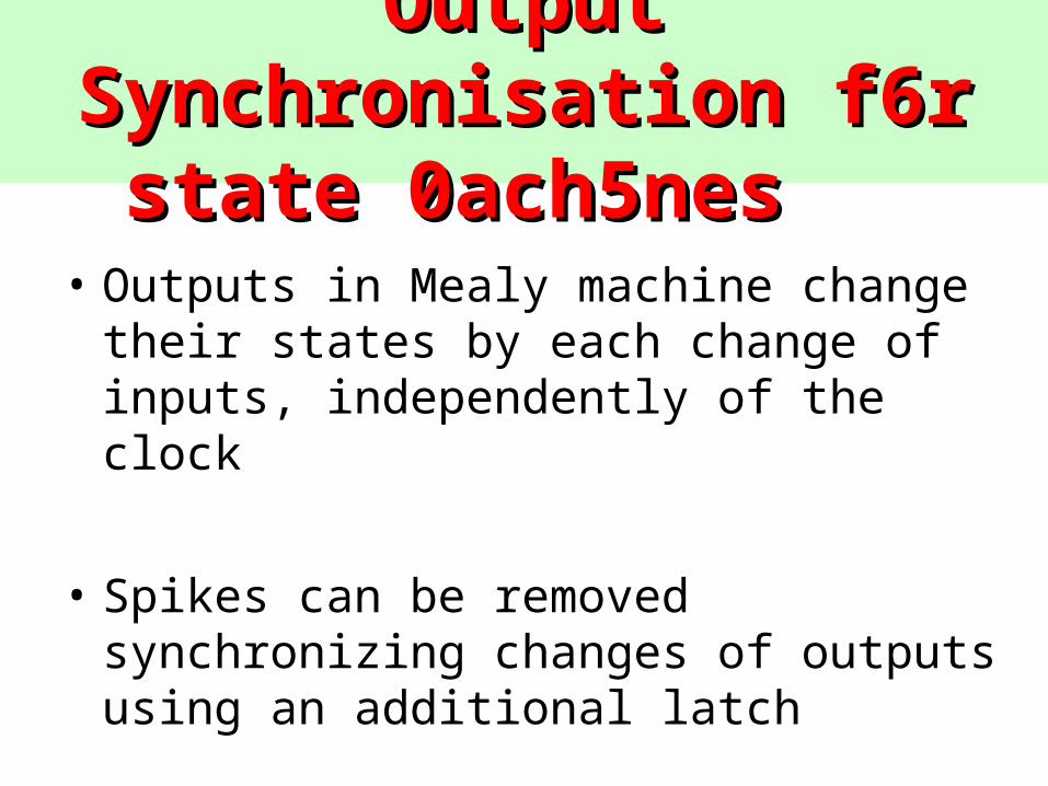
Output Output SynchroniSynchronisation f6r sation f6r state 0ach5nes state 0ach5nes
• Outputs in Mealy machine change their states by each change of inputs, independently of the clock
• Spikes can be removed synchronizing changes of outputs using an additional latch
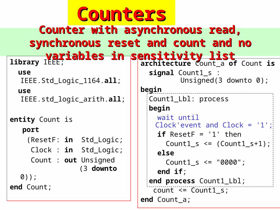
Counter with asynchronous read, synchronous reset and Counter with asynchronous read, synchronous reset and count and no variables in sensitivity listcount and no variables in sensitivity list
library IEEE; use
IEEE.Std_Logic_1164.all; use
IEEE.std_logic_arith.all;
entity Count is port (ResetF: in Std_Logic; Clock : in Std_Logic; Count : out Unsigned
(3 downto 0));
end Count;
architecture Count_a of Count is signal Count1_s :
Unsigned(3 downto 0);begin Count1_Lbl: process begin wait until
Clock'event and Clock = '1'; if ResetF = '1' then Count1_s <= (Count1_s+1); else Count1_s <= "0000"; end if; end process Count1_Lbl; count <= Count1_s; end Count_a;
CountersCounters
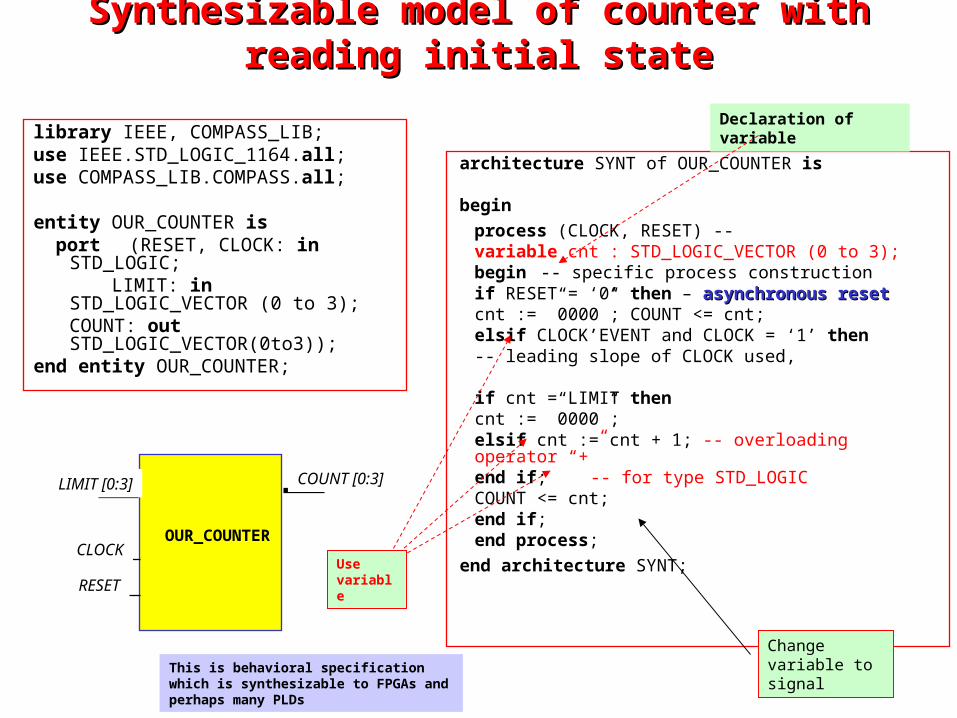
SyntSynthesizable hesizable model model of counter with reading initial stateof counter with reading initial state
library IEEE, COMPASS_LIB;use IEEE.STD_LOGIC_1164.all;use COMPASS_LIB.COMPASS.all;
entity OUR_COUNTER is port (RESET, CLOCK: in
STD_LOGIC; LIMIT: in STD_LOGIC_VECTOR (0 to
3);COUNT: out STD_LOGIC_VECTOR(0to3));
end entity OUR_COUNTER;
architecture SYNT of OUR_COUNTER is
begin
process (CLOCK, RESET) --variable cnt : STD_LOGIC_VECTOR (0 to 3);
begin -- specific process constructionif RESET = ‘0’ then – asynchronasynchronous resetous reset
cnt := ”0000”; COUNT <= cnt;elsif CLOCK’EVENT and CLOCK = ‘1’ then
-- leading slope of CLOCK used,
if cnt = LIMIT then cnt := ”0000”;
elsif cnt := cnt + 1; -- overloading operator “+” end if; -- for type STD_LOGICCOUNT <= cnt;
end if;end process;
end architecture SYNT;
OUR_COUNTER
LIMIT [0:3]
RESET
COUNT [0:3]
CLOCK
Declaration of variable
Use variable
Change variable to signalThis is behavioral specification which is
synthesizable to FPGAs and perhaps many PLDs
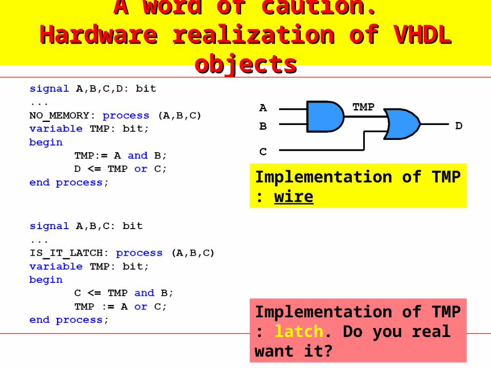
A word of caution.A word of caution.Hardware realization of VHDL objectsHardware realization of VHDL objects
Implementation of TMP : latch. Do you real want it?
Implementation of TMP : wire
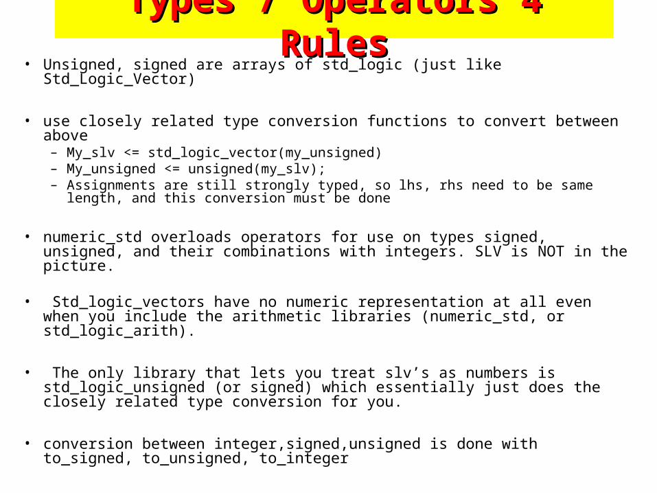
Types / Operators 4 RulesTypes / Operators 4 Rules• Unsigned, signed are arrays of std_logic (just like Std_Logic_Vector)
• use closely related type conversion functions to convert between above – My_slv <= std_logic_vector(my_unsigned)– My_unsigned <= unsigned(my_slv);– Assignments are still strongly typed, so lhs, rhs need to be same length, and this
conversion must be done
• numeric_std overloads operators for use on types signed, unsigned, and their combinations with integers. SLV is NOT in the picture.
• Std_logic_vectors have no numeric representation at all even when you
include the arithmetic libraries (numeric_std, or std_logic_arith).
• The only library that lets you treat slv’s as numbers is std_logic_unsigned (or signed) which essentially just does the closely related type conversion for you.
• conversion between integer,signed,unsigned is done with to_signed, to_unsigned, to_integer
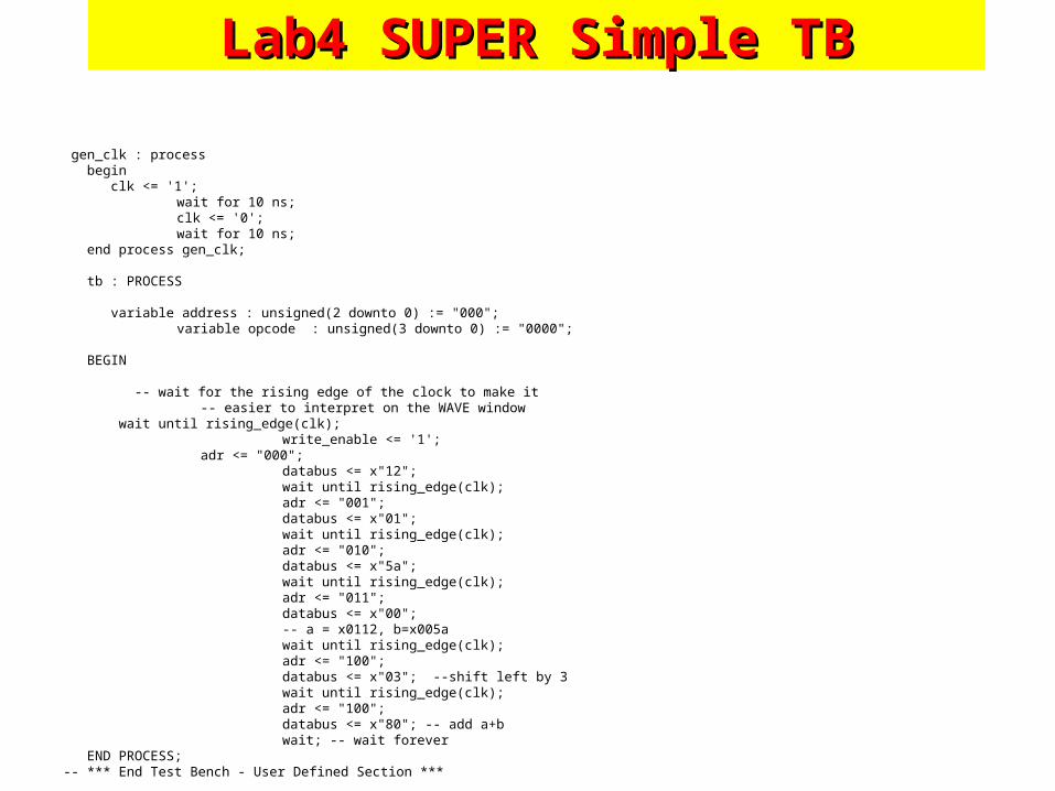
Lab4 SUPER Simple TBLab4 SUPER Simple TB
gen_clk : process begin clk <= '1';
wait for 10 ns; clk <= '0'; wait for 10 ns;
end process gen_clk;
tb : PROCESS
variable address : unsigned(2 downto 0) := "000"; variable opcode : unsigned(3 downto 0) := "0000";
BEGIN -- wait for the rising edge of the clock to make it
-- easier to interpret on the WAVE window wait until rising_edge(clk);
write_enable <= '1'; adr <= "000";
databus <= x"12"; wait until rising_edge(clk); adr <= "001"; databus <= x"01"; wait until rising_edge(clk); adr <= "010"; databus <= x"5a"; wait until rising_edge(clk); adr <= "011"; databus <= x"00"; -- a = x0112, b=x005a wait until rising_edge(clk); adr <= "100"; databus <= x"03"; --shift left by 3 wait until rising_edge(clk); adr <= "100"; databus <= x"80"; -- add a+b wait; -- wait forever
END PROCESS;-- *** End Test Bench - User Defined Section ***
Worked Example : StatemachinesWorked Example : Statemachines
• Use traffic light example
• Consider two templates
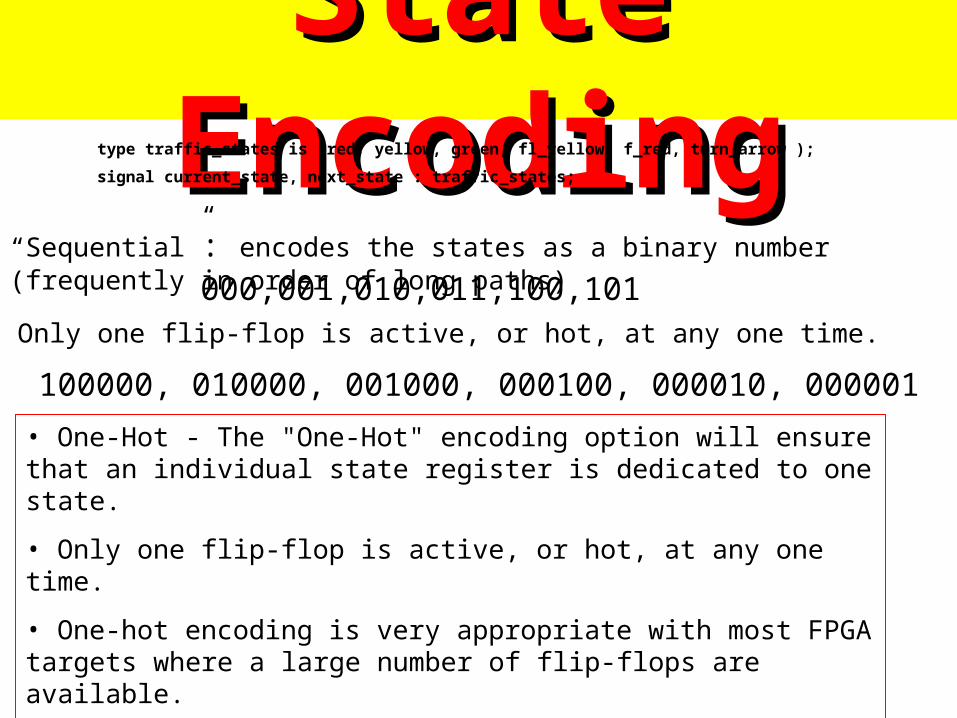
State EncodingState Encodingtype traffic_states is (red, yellow, green, fl_yellow, f_red, turn_arrow );
signal current_state, next_state : traffic_states;
“Sequential”: encodes the states as a binary number (frequently in order of long paths) 000,001,010,011,100,101
100000, 010000, 001000, 000100, 000010, 000001
• One-Hot - The "One-Hot" encoding option will ensure that an individual state register is dedicated to one state.
• Only one flip-flop is active, or hot, at any one time.
• One-hot encoding is very appropriate with most FPGA targets where a large number of flip-flops are available.
• It is also a good alternative when trying to optimize speed or to reduce power dissipation.
Only one flip-flop is active, or hot, at any one time.
State EncodingState Encoding
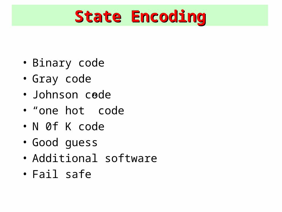
• Binary code• Gray code• Johnson code• “one hot” code• N 0f K code• Good guess• Additional software• Fail safe
State EncodingState Encoding
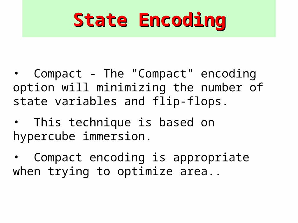
• Compact - The "Compact" encoding option will minimizing the number of state variables and flip-flops.
• This technique is based on hypercube immersion.
• Compact encoding is appropriate when trying to optimize area..
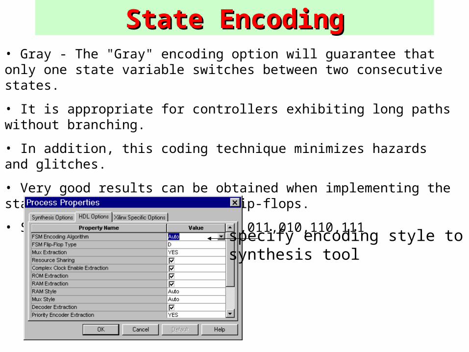
State EncodingState Encoding• Gray - The "Gray" encoding option will guarantee that only one state variable switches between two consecutive states.
• It is appropriate for controllers exhibiting long paths without branching.
• In addition, this coding technique minimizes hazards and glitches.
• Very good results can be obtained when implementing the state register with T or JK flip-flops.
• State reg might go … 000,001,011,010,110,111
specify encoding style to synthesis tool
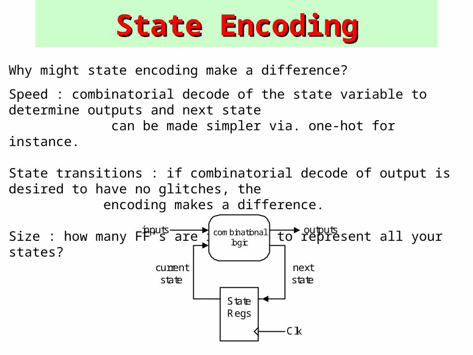
State EncodingState EncodingWhy might state encoding make a difference?
Speed : combinatorial decode of the state variable to determine outputs and next state can be made simpler via. one-hot for instance.
State transitions : if combinatorial decode of output is desired to have no glitches, the encoding makes a difference.
Size : how many FF’s are required to represent all your states?
Clk
StateRegs
combinationallogic
inputs outputs
currentstate
nextstate
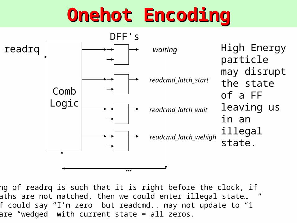
Onehot EncodingOnehot EncodingDFF’s
waiting
readcmd_latch_start
readcmd_latch_wait
readcmd_latch_wehigh
…
CombLogic
readrq
If timing of readrq is such that it is right before the clock, ifdelay paths are not matched, then we could enter illegal state…(wait ff could say “I’m zero” but readcmd.. may not update to “1”Now we are “wedged” with current state = all zeros.
High Energy particle may disrupt the state of a FF leaving us in an illegal state.
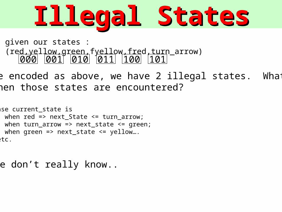
Illegal StatesIllegal Statesgiven our states : (red,yellow,green,fyellow,fred,turn_arrow)
000 001 010 011 100 101
if they are encoded as above, we have 2 illegal states. What will logic do when those states are encountered?
case current_state is when red => next_State <= turn_arrow; when turn_arrow => next_state <= green; when green => next_state <= yellow….…etc.
We don’t really know..
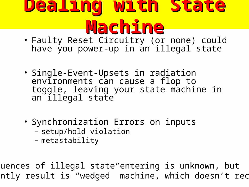
Dealing with State MachineDealing with State Machine• Faulty Reset Circuitry (or none) could have you
power-up in an illegal state
• Single-Event-Upsets in radiation environments can cause a flop to toggle, leaving your state machine in an illegal state
• Synchronization Errors on inputs– setup/hold violation– metastability
Consequences of illegal state entering is unknown, but frequently result is “wedged” machine, which doesn’t recover
Example MachineExample Machine
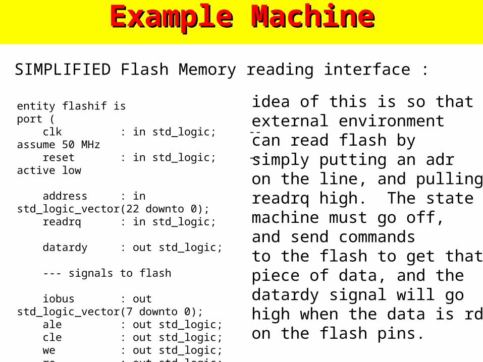
SIMPLIFIED Flash Memory reading interface :
entity flashif isport ( clk : in std_logic; -- assume 50 MHz reset : in std_logic; -- active low
address : in std_logic_vector(22 downto 0); readrq : in std_logic; datardy : out std_logic; --- signals to flash
iobus : out std_logic_vector(7 downto 0); ale : out std_logic; cle : out std_logic; we : out std_logic; re : out std_logic; ready_busy_b: in std_logic);
idea of this is so thatexternal environmentcan read flash bysimply putting an adron the line, and pullingreadrq high. The statemachine must go off, and send commandsto the flash to get thatpiece of data, and thedatardy signal will gohigh when the data is rdyon the flash pins.
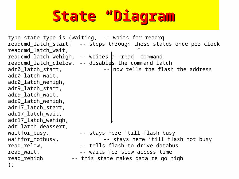
State “Diagram”State “Diagram”type state_type is (waiting, -- waits for readrqreadcmd_latch_start, -- steps through these states once per clockreadcmd_latch_wait,readcmd_latch_wehigh, -- writes a “read” commandreadcmd_latch_clelow, -- disables the command latchadr0_latch_start, -- now tells the flash the addressadr0_latch_wait,adr0_latch_wehigh,adr9_latch_start,adr9_latch_wait,adr9_latch_wehigh,adr17_latch_start,adr17_latch_wait,adr17_latch_wehigh,adr_latch_deassert,waitfor_busy, -- stays here ‘till flash busywaitfor_notbusy, -- stays here ‘till flash not busyread_relow, -- tells flash to drive databusread_wait, -- waits for slow access timeread_rehigh -- this state makes data re go high);
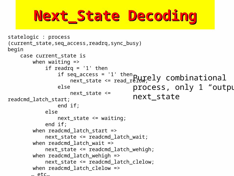
Next_State DecodingNext_State Decodingstatelogic : process (current_state,seq_access,readrq,sync_busy)begin case current_state is when waiting => if readrq = '1' then if seq_access = '1' then next_state <= read_relow; else next_state <= readcmd_latch_start; end if; else next_state <= waiting; end if; when readcmd_latch_start => next_state <= readcmd_latch_wait; when readcmd_latch_wait => next_state <= readcmd_latch_wehigh; when readcmd_latch_wehigh => next_state <= readcmd_latch_clelow; when readcmd_latch_clelow =>
… etc…
Purely combinationalprocess, only 1 “output”next_state
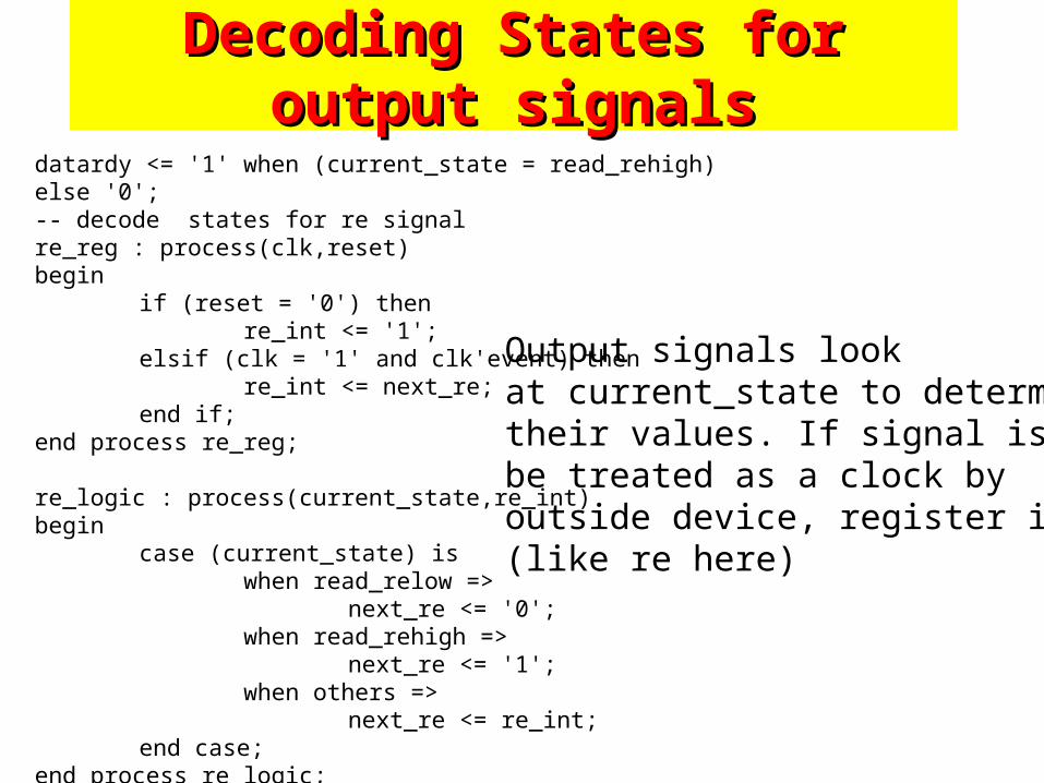
Decoding States for output signalsDecoding States for output signals
datardy <= '1' when (current_state = read_rehigh) else '0'; -- decode states for re signal re_reg : process(clk,reset)begin
if (reset = '0') thenre_int <= '1';
elsif (clk = '1' and clk'event) then re_int <= next_re;
end if;end process re_reg;
re_logic : process(current_state,re_int)begin
case (current_state) iswhen read_relow =>
next_re <= '0';when read_rehigh =>
next_re <= '1';when others =>
next_re <= re_int;end case;
end process re_logic;
Output signals look at current_state to determinetheir values. If signal is tobe treated as a clock by outside device, register it…(like re here)
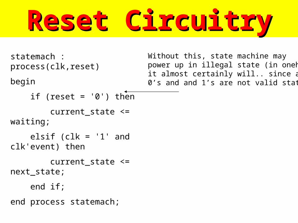
Reset CircuitryReset Circuitrystatemach : process(clk,reset)
begin
if (reset = '0') then
current_state <= waiting;
elsif (clk = '1' and clk'event) then
current_state <= next_state;
end if;
end process statemach;
Without this, state machine maypower up in illegal state (in onehotit almost certainly will.. since all0’s and and 1’s are not valid states)
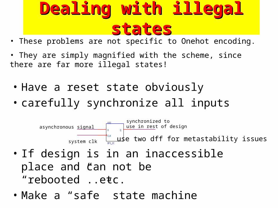
Dealing with illegal statesDealing with illegal states
• Have a reset state obviously
• carefully synchronize all inputs
• If design is in an inaccessible place and can not be “rebooted”..etc.
• Make a “safe” state machine
• These problems are not specific to Onehot encoding.
• They are simply magnified with the scheme, since there are far more illegal states!
U32
DF1_CC
D Q
CLK
asynchronous signal
system clk
synchronized to use in rest of design
use two dff for metastability issues
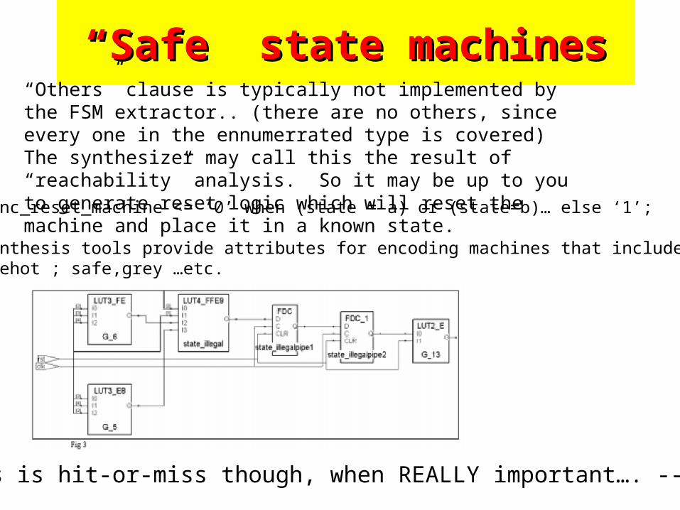
““Safe” state machinesSafe” state machines“Others” clause is typically not implemented by the FSM extractor.. (there are no others, since every one in the ennumerrated type is covered) The synthesizer may call this the result of “reachability” analysis. So it may be up to you to generate reset logic which will reset the machine and place it in a known state.
i.e. sync_reset_machine <= ‘0’ when (state = a) or (state=b)… else ‘1’;
Some synthesis tools provide attributes for encoding machines that include :safe,onehot ; safe,grey …etc.
This is hit-or-miss though, when REALLY important…. -->
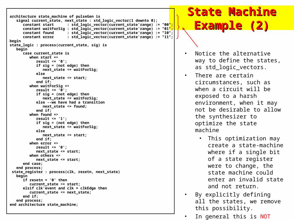
State Machine Example State Machine Example (2)(2)
architecture state_machine of pulseGen is signal current_state, next_state : std_logic_vector(1 downto 0); constant start : std_logic_vector(current_state'range) := "00"; constant waitForSig : std_logic_vector(current_state'range) := "01"; constant found : std_logic_vector(current_state'range) := "10"; constant error : std_logic_vector(current_state'range) := "11";beginstate_logic : process(current_state, sig) is begin case current_state is when start => result <= '0'; if sig = (not edge) then next_state <= waitForSig; else next_state <= start; end if; when waitForSig => result <= '0'; if sig = (not edge) then next_state <= waitForSig; else --we have had a transition next_state <= found; end if; when found => result <= '1'; if sig = (not edge) then next_state <= waitForSig; else next_state <= start; end if; when error => result <= '0'; next_state <= start; when others => next_state <= start; end case; end process; state_register : process(clk, resetn, next_state) begin if resetn = '0' then current_state <= start; elsif clk'event and clk = clkEdge then current_state <= next_state; end if; end process;end architecture state_machine;
• Notice the alternative way to define the states, as std_logic_vectors.
• There are certain circumstances, such as when a circuit will be exposed to a harsh environment, when it may not be desirable to allow the synthesizer to optimize the state machine
• This optimization may create a state-machine where if a single bit of a state register were to change, the state machine could enter an invalid state and not return.
• By explicitly defining all the states, we remove this possibility.
• In general this is NOT need – it is recommended that enumerated types be used to define states.
• TURN FSM Extraction OFF

Exam MaterialExam Materialall material covered in class, homeworks, and assigned book all material covered in class, homeworks, and assigned book
chapters is fair , however here are some particularschapters is fair , however here are some particulars
• you should be able to quickly construct basic design elements in synthesizable vhdl.– e.g. make a d-flipflop w/ enable
• state machines• simulation vs. synthesis• mechanics of a process• given simple design constraints, make synthesizable
entity/architecture pair
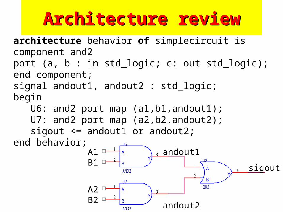
Architecture reviewArchitecture reviewarchitecture behavior of simplecircuit iscomponent and2 port (a, b : in std_logic; c: out std_logic);end component;signal andout1, andout2 : std_logic;begin U6: and2 port map (a1,b1,andout1); U7: and2 port map (a2,b2,andout2); sigout <= andout1 or andout2;end behavior;
A
BY
U6
AND2
1
23
A
BY
U7
AND2
1
23
A
BY
U8
OR2
1
23 sigout
andout2
andout1A1
A2
B1
B2
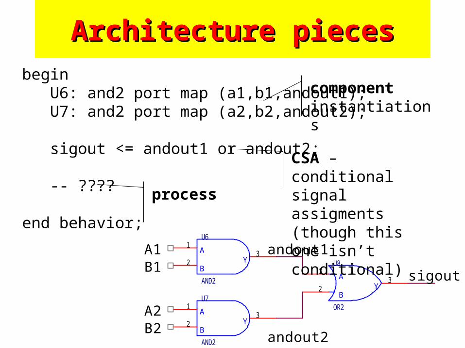
begin U6: and2 port map (a1,b1,andout1); U7: and2 port map (a2,b2,andout2);
sigout <= andout1 or andout2;
-- ????
end behavior;
Architecture piecesArchitecture pieces
A
BY
U6
AND2
1
23
A
BY
U7
AND2
1
23
A
BY
U8
OR2
1
23 sigout
andout2
andout1A1
A2
B1
B2
component instantiations
CSA – conditional signal assigments(though this one isn’t conditional)
process
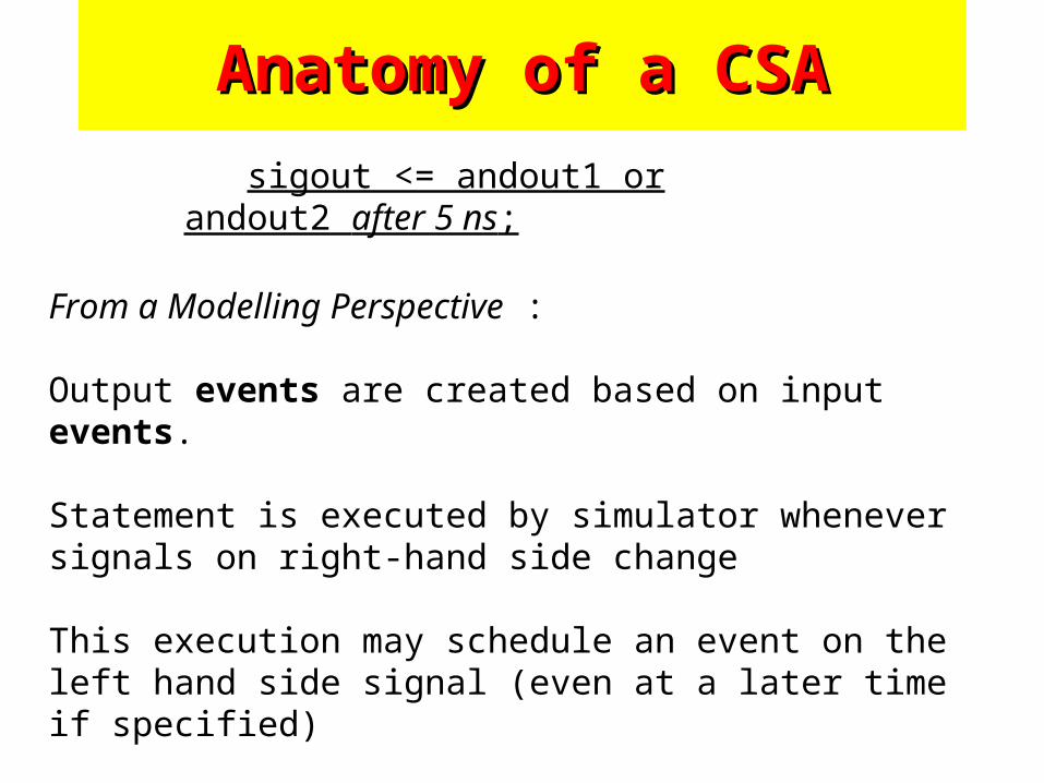
From a Modelling Perspective :
Output events are created based on input events.
Statement is executed by simulator whenever signals on right-hand side change
This execution may schedule an event on the left hand side signal (even at a later time if specified)
sigout <= andout1 or andout2 after 5 ns;
Anatomy of a CSAAnatomy of a CSA
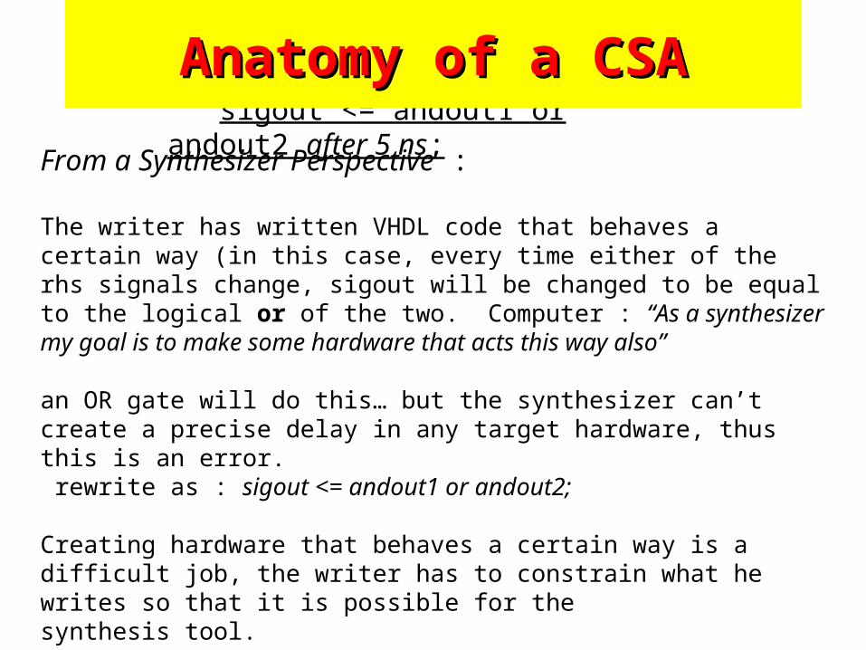
From a Synthesizer Perspective :
The writer has written VHDL code that behaves a certain way (in this case, every time either of the rhs signals change, sigout will be changed to be equal to the logical or of the two. Computer : “As a synthesizer my goal is to make some hardware that acts this way also”
an OR gate will do this… but the synthesizer can’t create a precise delay in any target hardware, thus this is an error. rewrite as : sigout <= andout1 or andout2;
Creating hardware that behaves a certain way is a difficult job, the writer has to constrain what he writes so that it is possible for thesynthesis tool.
sigout <= andout1 or andout2 after 5 ns;
Anatomy of a CSAAnatomy of a CSA
VHDL domains :
concurrent domain – architecture describes activities that happen simultaneouslycomponent instances, CSAs, processes
sequential domain -- within a processdescribes activities that happen in a defined ordersimilar to standard programming languages
Definition : a process is a series of sequential statements that must be “executed” in order. *(talking from simulator perspective)
ProcessesProcesses
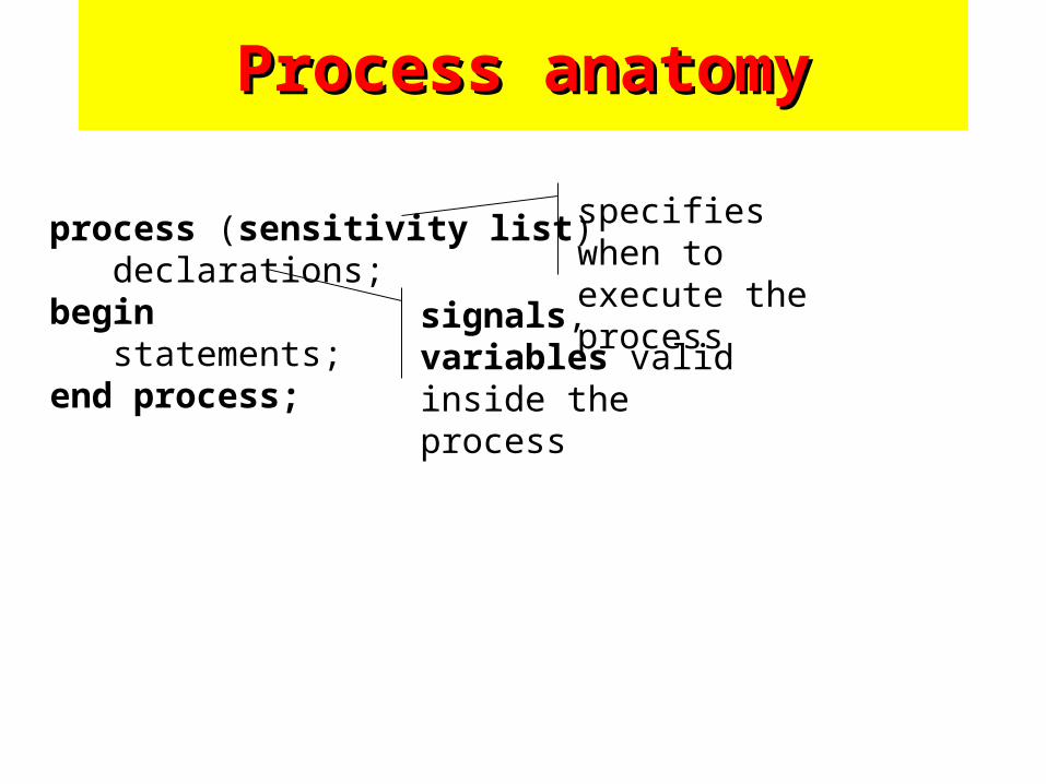
process (sensitivity list) declarations;begin statements;end process;
Process anatomyProcess anatomy
specifies when to execute the process
signals, variables valid inside the process
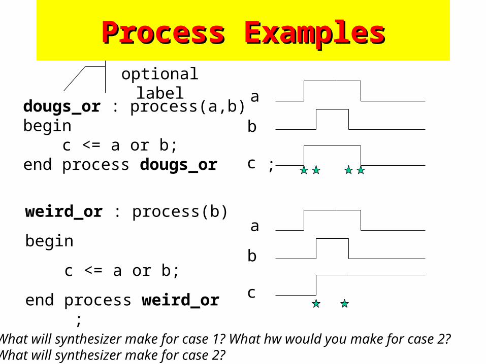
dougs_or : process(a,b)begin c <= a or b;end process dougs_or ;
Process ExamplesProcess Examplesoptional label
weird_or : process(b)
begin
c <= a or b;
end process weird_or ;
a
b
c
a
b
c
What will synthesizer make for case 1? What hw would you make for case 2?What will synthesizer make for case 2?
Process ExamplesProcess Examples
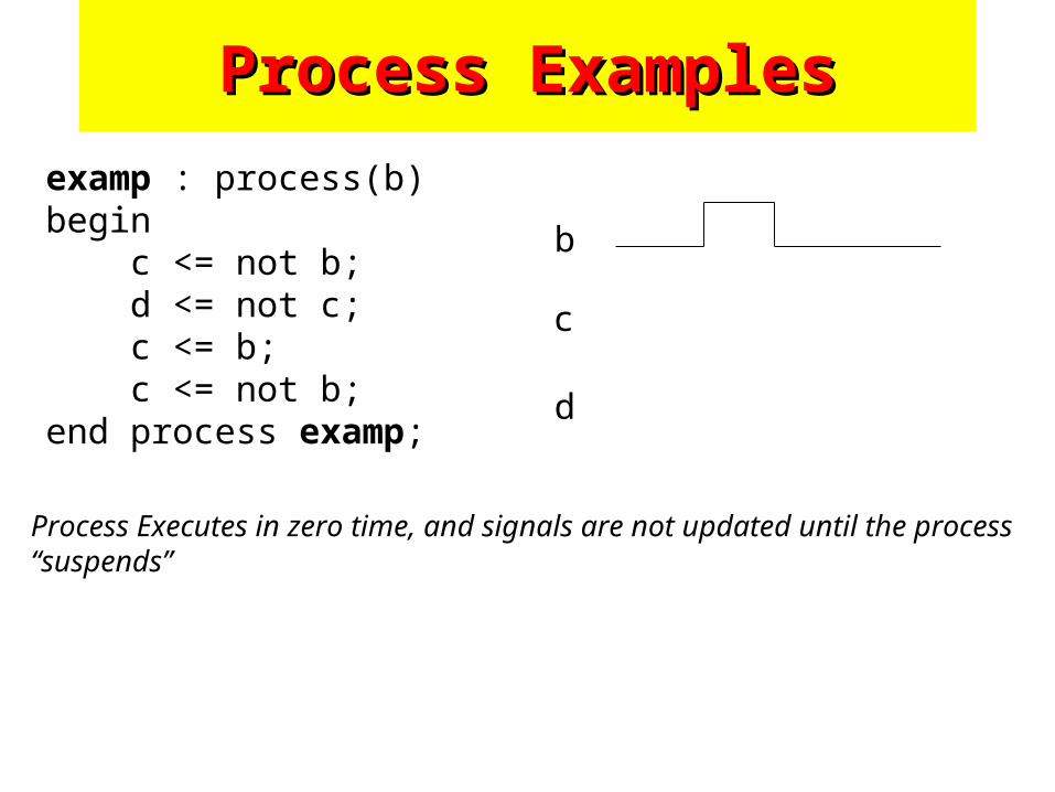
examp : process(b)begin c <= not b; d <= not c; c <= b; c <= not b;end process examp;
b
c
Process Executes in zero time, and signals are not updated until the process “suspends”
d
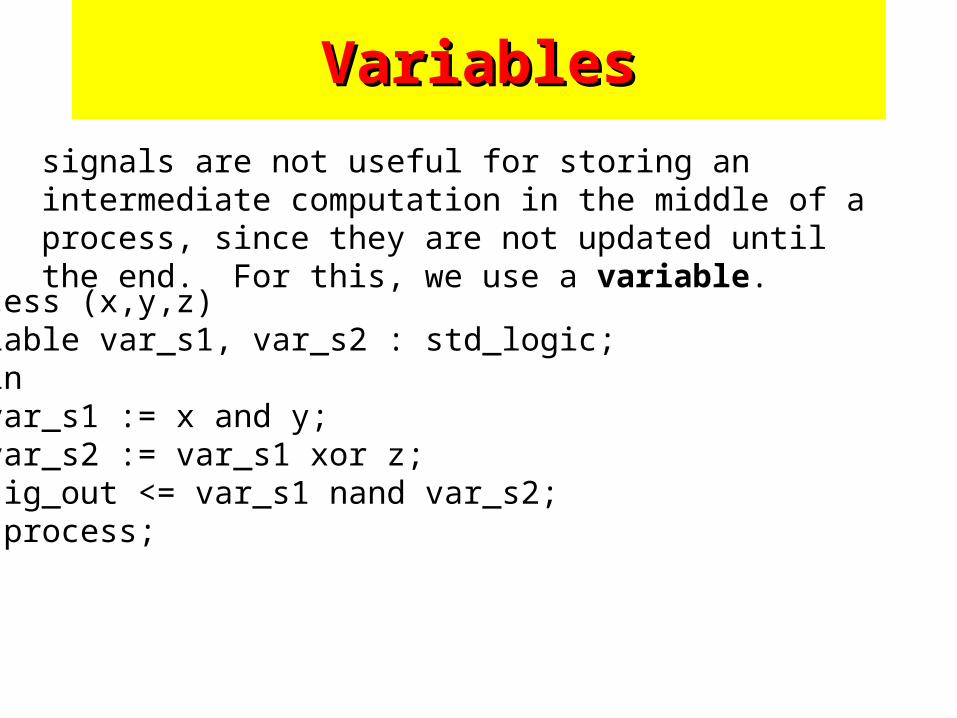
VariablesVariables
signals are not useful for storing an intermediate computation in the middle of a process, since they are not updated until the end. For this, we use a variable.
process (x,y,z)variable var_s1, var_s2 : std_logic;begin var_s1 := x and y; var_s2 := var_s1 xor z; sig_out <= var_s1 nand var_s2;end process;
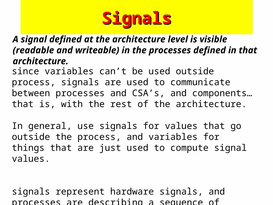
SignalsSignals
since variables can’t be used outside process, signals are used to communicate between processes and CSA’s, and components… that is, with the rest of the architecture.
In general, use signals for values that go outside the process, and variables for things that are just used to compute signal values.
signals represent hardware signals, and processes are describing a sequence of computations to determine what values to assign to those signals.
A signal defined at the architecture level is visible (readable and writeable) in the processes defined in that architecture.
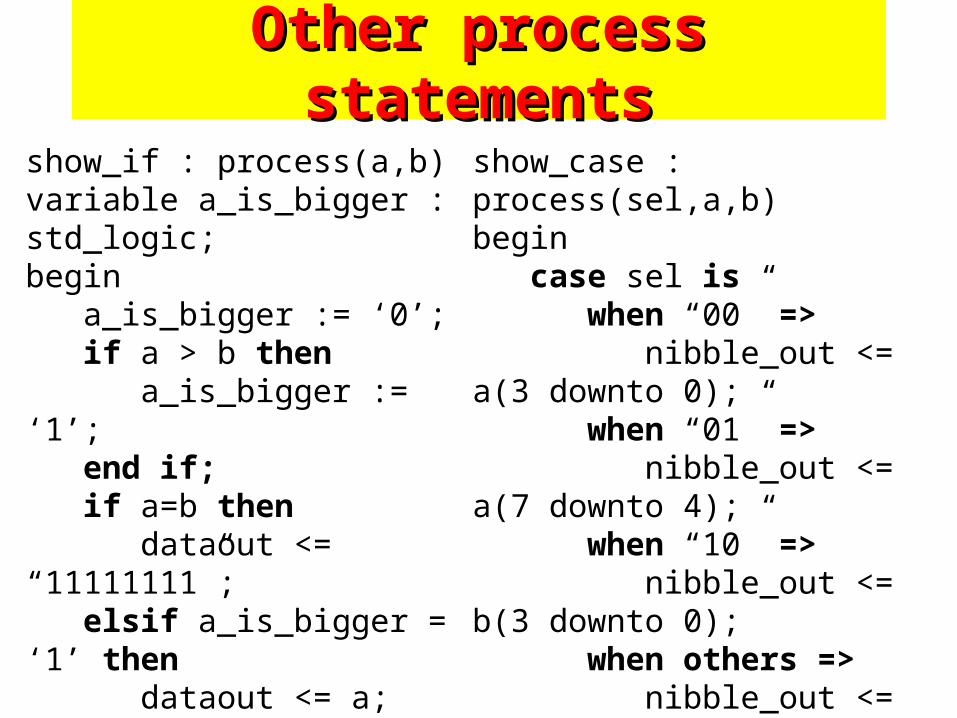
Other process statementsOther process statements
show_if : process(a,b)variable a_is_bigger : std_logic;begin a_is_bigger := ‘0’; if a > b then a_is_bigger := ‘1’; end if; if a=b then dataout <= “11111111”; elsif a_is_bigger = ‘1’ then dataout <= a; else dataout <= b; end if; end process show_if;
show_case : process(sel,a,b)begin case sel is when “00” => nibble_out <= a(3 downto 0); when “01” => nibble_out <= a(7 downto 4); when “10” => nibble_out <= b(3 downto 0); when others => nibble_out <= b(7 downto 4); end case;end process show_case;
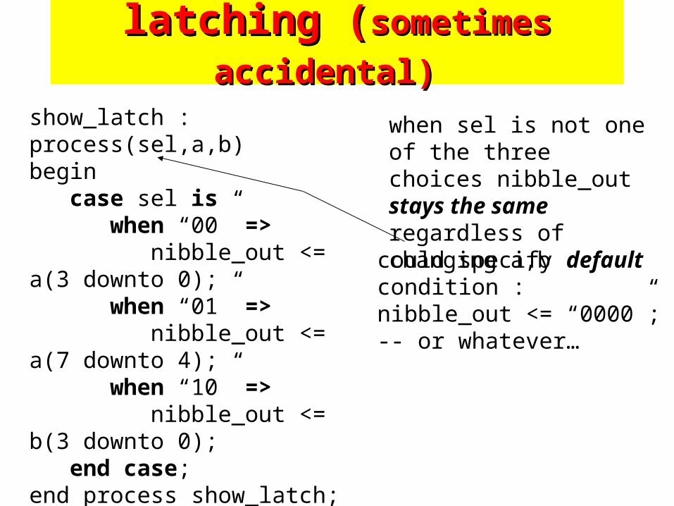
latching (latching (sometimes accidental)sometimes accidental)
show_latch : process(sel,a,b)begin case sel is when “00” => nibble_out <= a(3 downto 0); when “01” => nibble_out <= a(7 downto 4); when “10” => nibble_out <= b(3 downto 0); end case;end process show_latch;
when sel is not one of the three choices nibble_out stays the same regardless of changing a,b
could specify defaultcondition :nibble_out <= “0000”;-- or whatever…
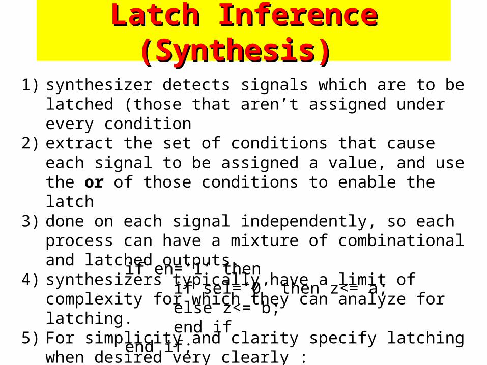
Latch Inference (Synthesis) Latch Inference (Synthesis)
1) synthesizer detects signals which are to be latched (those that aren’t assigned under every condition
2) extract the set of conditions that cause each signal to be assigned a value, and use the or of those conditions to enable the latch
3) done on each signal independently, so each process can have a mixture of combinational and latched outputs.
4) synthesizers typically have a limit of complexity for which they can analyze for latching.
5) For simplicity and clarity specify latching when desired very clearly :
if en=‘1’ thenif sel=‘0’ then z<= a;else z<= b;end if
end if;
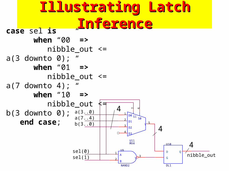
Illustrating Latch InferenceIllustrating Latch Inference
A
BY
U9
NAND2
1
23
U10
DL1
D Q
G
D0
D1
D2
D3
Y
S1S0
U11MX4
1
2
3
4
67
5
a(3..0)
b(3..0)a(7..4)
sel(1)sel(0)
nibble_out
case sel is when “00” => nibble_out <= a(3 downto 0); when “01” => nibble_out <= a(7 downto 4); when “10” => nibble_out <= b(3 downto 0); end case;
4
4
4
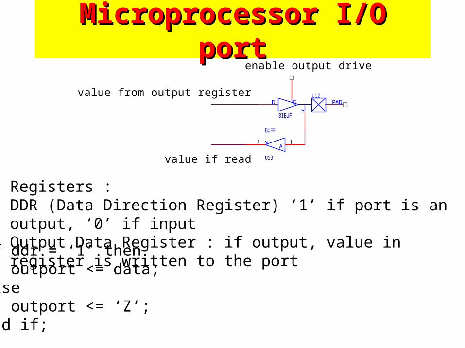
Microprocessor I/O portMicroprocessor I/O port
PADD E
Y
U12
BIBUF
AY
U13
BUFF
12
value from output register
value if read
enable output drive
Registers : DDR (Data Direction Register) ‘1’ if port is an output, ‘0’ if inputOutput Data Register : if output, value in register is written to the port
if ddr = ‘1’ then outport <= data;else outport <= ‘Z’;end if;
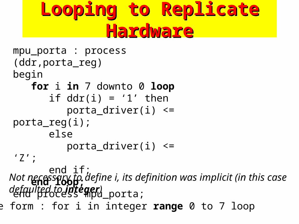
Looping to Replicate HardwareLooping to Replicate Hardware
mpu_porta : process (ddr,porta_reg)begin for i in 7 downto 0 loop if ddr(i) = ‘1’ then porta_driver(i) <= porta_reg(i); else porta_driver(i) <= ‘Z’; end if; end loop;end process mpu_porta;
Not necessary to define i, its definition was implicit (in this case defaulted to integer)
complete form : for i in integer range 0 to 7 loop
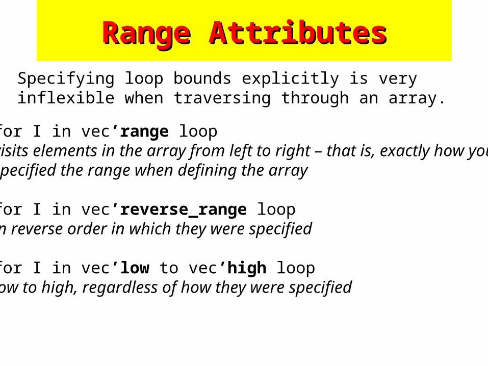
Range AttributesRange Attributes
Specifying loop bounds explicitly is very inflexible when traversing through an array.
for I in vec’range loopvisits elements in the array from left to right – that is, exactly how youspecified the range when defining the array
for I in vec’reverse_range loopin reverse order in which they were specified
for I in vec’low to vec’high looplow to high, regardless of how they were specified
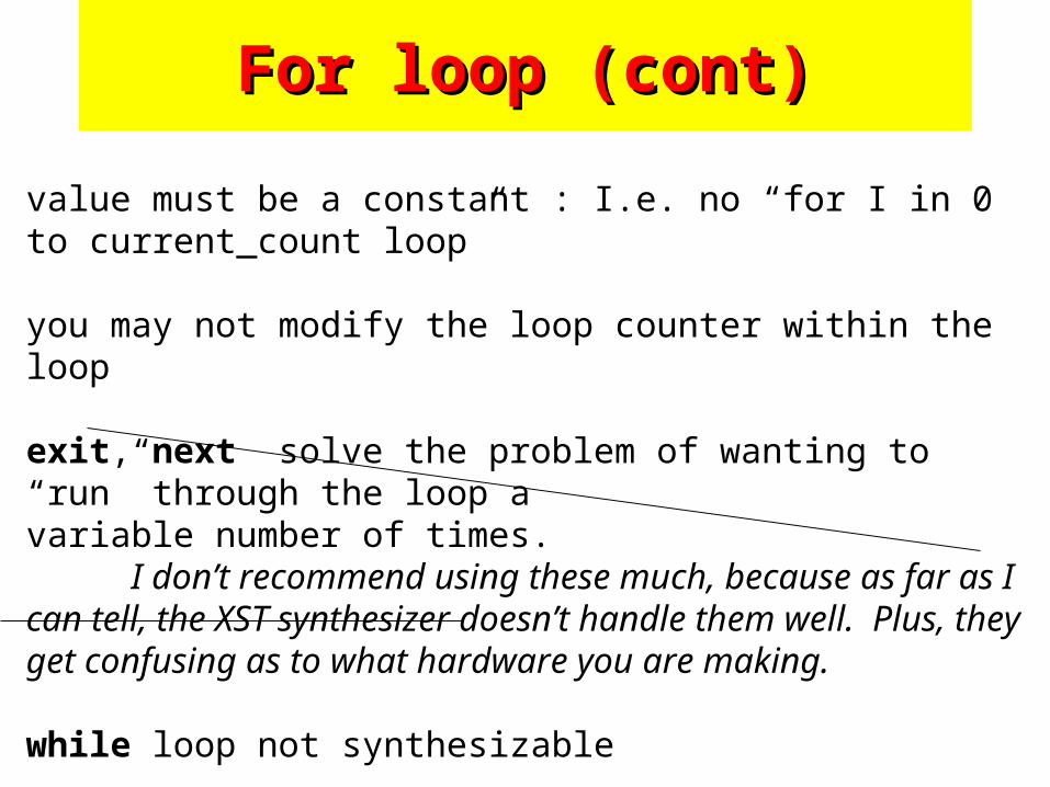
For loop (cont)For loop (cont)
value must be a constant : I.e. no “for I in 0 to current_count loop”
you may not modify the loop counter within the loop
exit, next solve the problem of wanting to “run” through the loop a variable number of times.
I don’t recommend using these much, because as far as I can tell, the XST synthesizer doesn’t handle them well. Plus, they get confusing as to what hardware you are making.
while loop not synthesizable
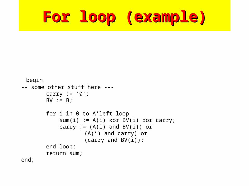
For loop (example)For loop (example)
begin-- some other stuff here ---
carry := '0';BV := B;
for i in 0 to A'left loop sum(i) := A(i) xor BV(i) xor carry; carry := (A(i) and BV(i)) or
(A(i) and carry) or (carry and BV(i));
end loop;return sum;
end;
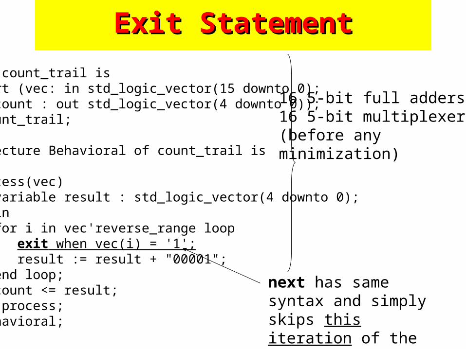
Exit StatementExit Statement
entity count_trail is Port (vec: in std_logic_vector(15 downto 0);
count : out std_logic_vector(4 downto 0));end count_trail;
architecture Behavioral of count_trail isbegin process(vec) variable result : std_logic_vector(4 downto 0); begin for i in vec'reverse_range loop exit when vec(i) = '1'; result := result + "00001"; end loop; count <= result; end process;end Behavioral;
next has same syntax and simply skips this iteration of the loop
16 5-bit full adders16 5-bit multiplexers(before any minimization)
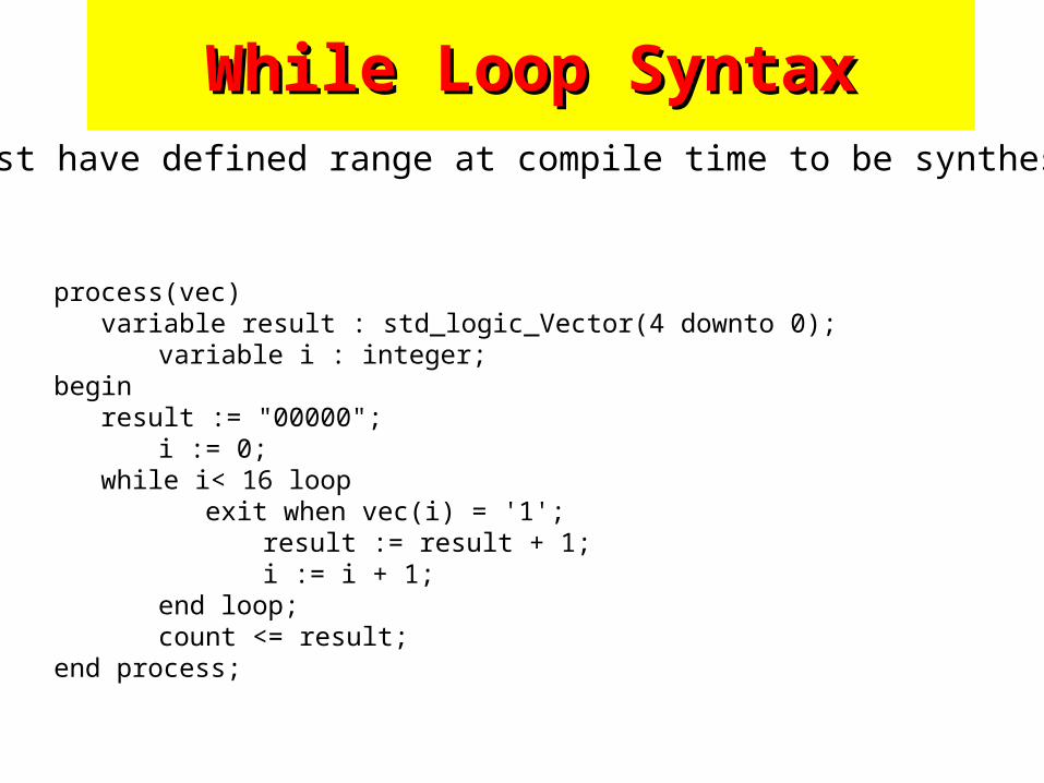
While Loop SyntaxWhile Loop Syntax
process(vec) variable result : std_logic_Vector(4 downto 0);
variable i : integer;begin result := "00000";
i := 0; while i< 16 loop
exit when vec(i) = '1';result := result + 1;i := i + 1;
end loop;count <= result;
end process;
must have defined range at compile time to be synthesized
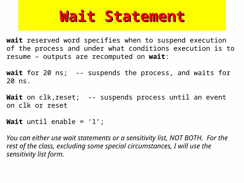
Wait StatementWait Statement
wait reserved word specifies when to suspend execution of the process and under what conditions execution is to resume – outputs are recomputed on wait: wait for 20 ns; -- suspends the process, and waits for 20 ns. Wait on clk,reset; -- suspends process until an event on clk or reset Wait until enable = ‘1’; You can either use wait statements or a sensitivity list, NOT BOTH. For the rest of the class, excluding some special circumstances, I will use the sensitivity list form.
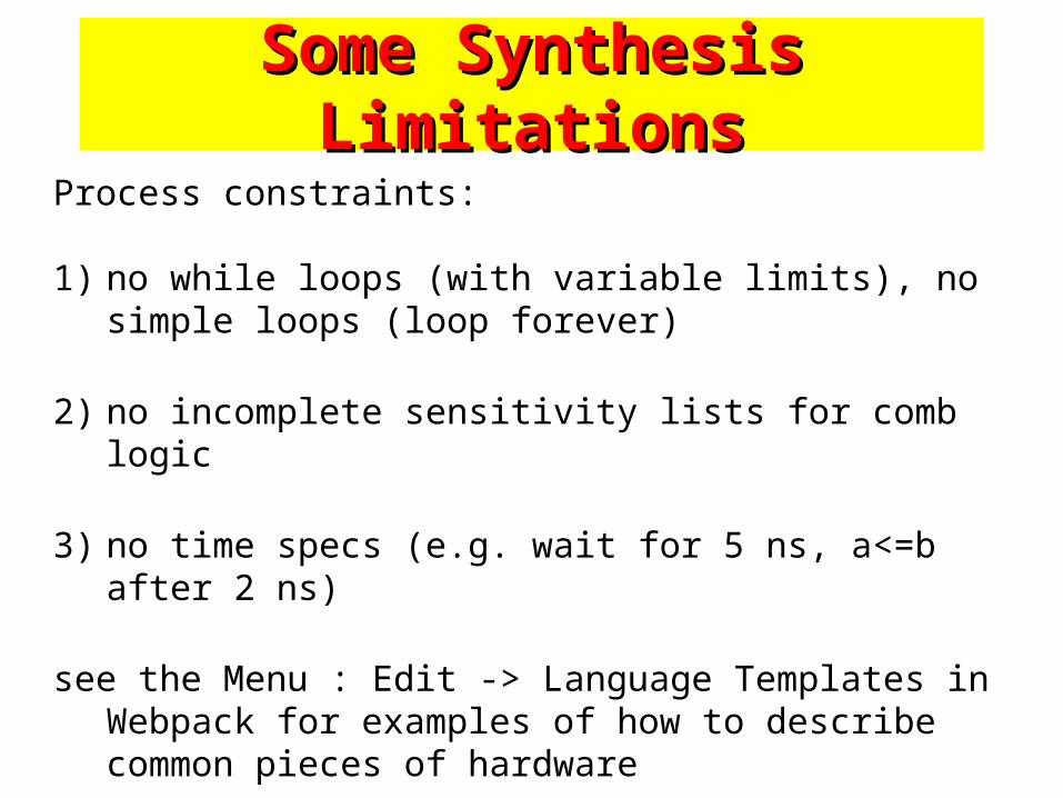
Some Synthesis LimitationsSome Synthesis Limitations
Process constraints:
1) no while loops (with variable limits), no simple loops (loop forever)
2) no incomplete sensitivity lists for comb logic
3) no time specs (e.g. wait for 5 ns, a<=b after 2 ns)
see the Menu : Edit -> Language Templates in Webpack for examples of how to describe common pieces of hardware
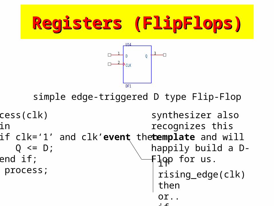
Registers (FlipFlops)Registers (FlipFlops)U14
DF1
D1
Q3
CLK2
simple edge-triggered D type Flip-Flop
process(clk)begin if clk=‘1’ and clk’event then Q <= D; end if;end process;
synthesizer also recognizes this template and will happily build a D-Flop for us.
if rising_edge(clk) thenor..if falling_edge(clk) then
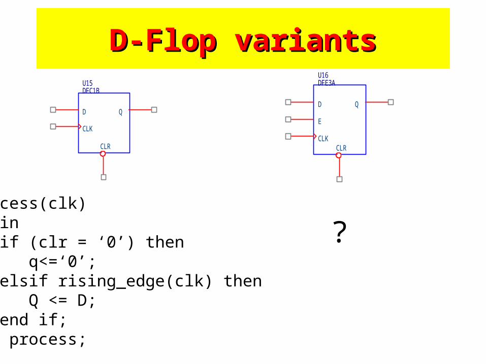
D-Flop variantsD-Flop variants
process(clk)begin if (clr = ‘0’) then q<=‘0’; elsif rising_edge(clk) then Q <= D; end if;end process;
U15DFC1B
D Q
CLK
CLR
U16DFE3A
D
E
CLKCLR
Q
?
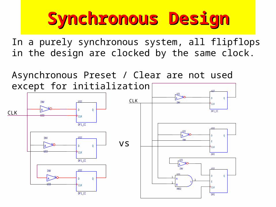
Synchronous DesignSynchronous DesignIn a purely synchronous system, all flipflops in the design are clocked by the same clock.
Asynchronous Preset / Clear are not used except for initialization
U27
DF1_CC
D Q
CLK
A YU31
INV
U32
DFE
D Q
CLK
E
U32
DFE
D Q
CLK
E
A YU31
INV
A
BY
U33
AND2
1
23
A YU31
INV
CLK
vs
U32
DF1_CC
D Q
CLK
A Y
U33
INV
U32
DF1_CC
D Q
CLK
A Y
U33
INV
U32
DF1_CC
D Q
CLK
A Y
U33
INV
CLK
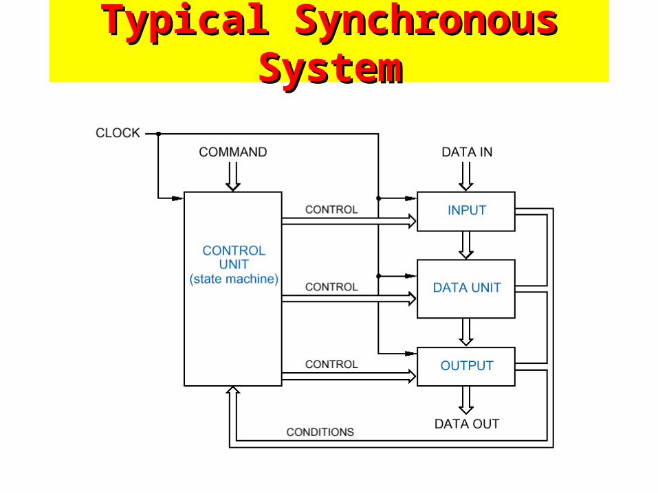
Typical Synchronous SystemTypical Synchronous System
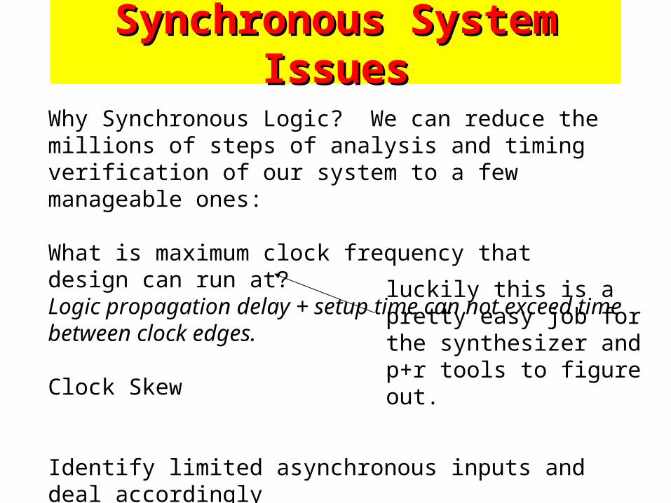
Why Synchronous Logic? We can reduce the millions of steps of analysis and timing verification of our system to a few manageable ones:
What is maximum clock frequency that design can run at?Logic propagation delay + setup time can not exceed time between clock edges.
Clock Skew
Identify limited asynchronous inputs and deal accordingly
Synchronous System IssuesSynchronous System Issues
luckily this is a pretty easy job for the synthesizer and p+r tools to figure out.
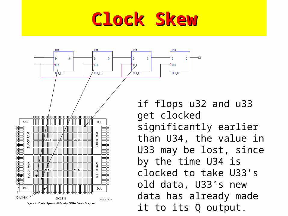
Clock SkewClock Skew
U32
DF1_CC
D Q
CLK
U33
DF1_CC
D Q
CLK
U34
DF1_CC
D Q
CLK
U35
DF1_CC
D Q
CLK
if flops u32 and u33 get clocked significantly earlier than U34, the value in U33 may be lost, since by the time U34 is clocked to take U33’s old data, U33’s new data has already made it to its Q output.
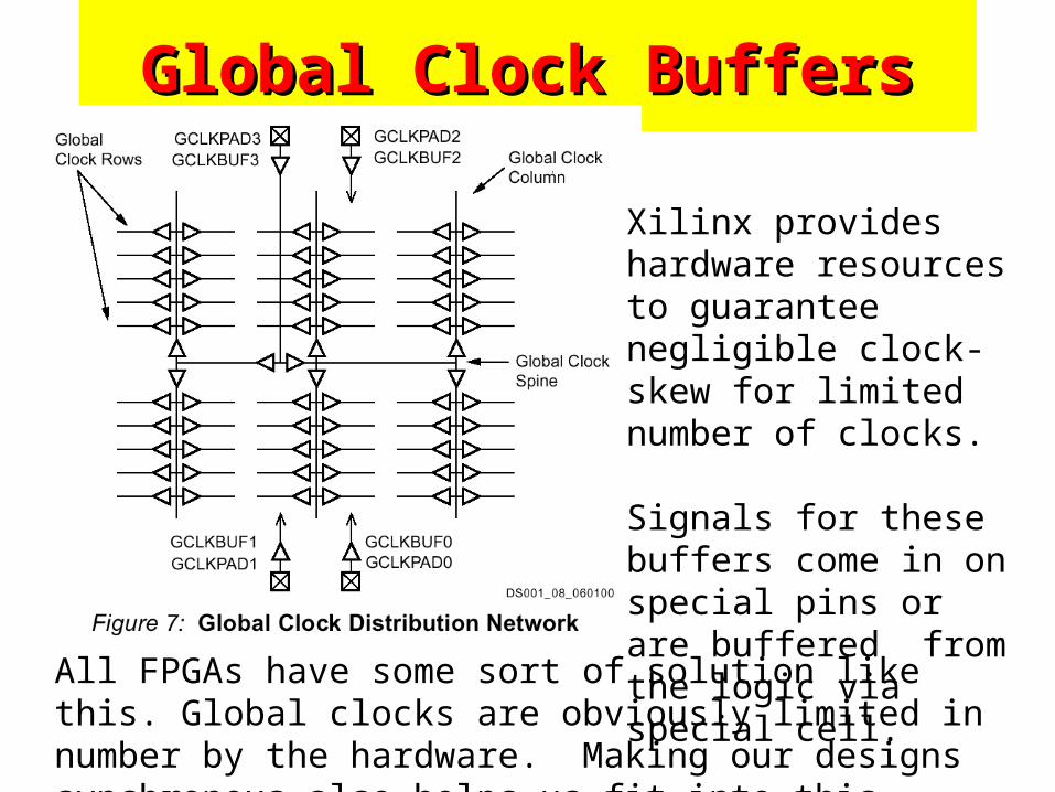
Global Clock BuffersGlobal Clock Buffers
All FPGAs have some sort of solution like this. Global clocks are obviously limited in number by the hardware. Making our designs synchronous also helps us fit into this architecture.
Xilinx provides hardware resources to guarantee negligible clock-skew for limited number of clocks.
Signals for these buffers come in on special pins or are buffered from the logic via special cell.
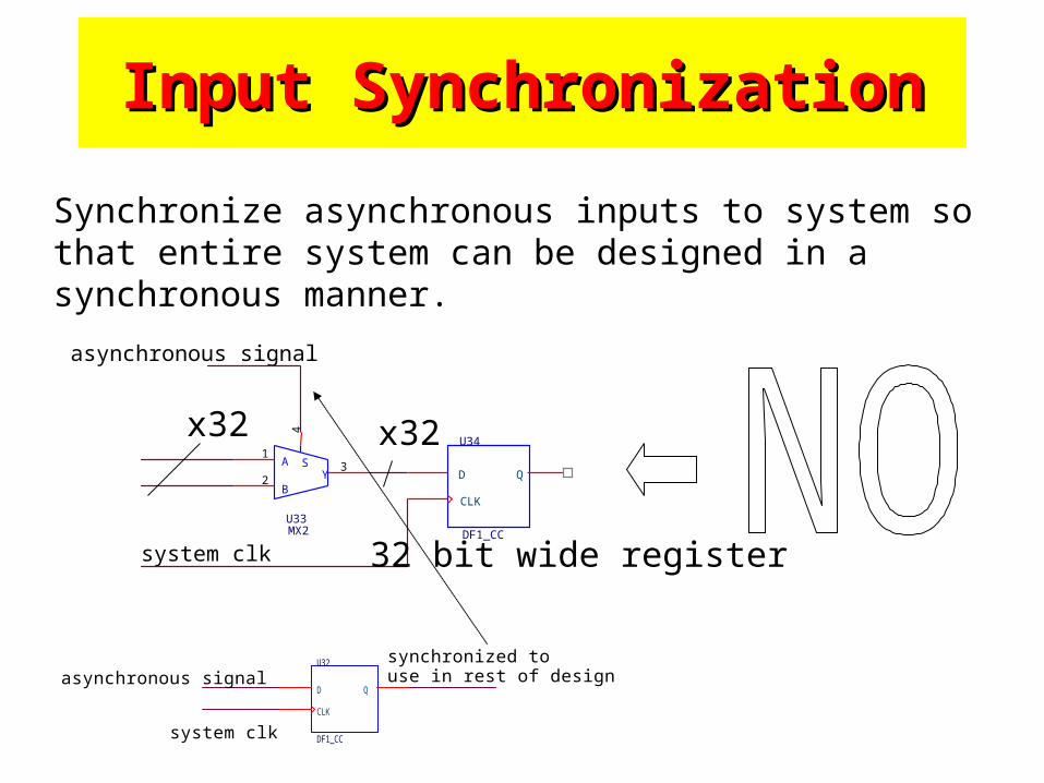
Input SynchronizationInput Synchronization
Synchronize asynchronous inputs to system so that entire system can be designed in a synchronous manner.
U32
DF1_CC
D Q
CLK
asynchronous signal
system clk
synchronized to use in rest of design
A
BY
S
U33MX2
1
2
4
3
U34
DF1_CC
D Q
CLK
asynchronous signal
system clk
x32 x32
32 bit wide register
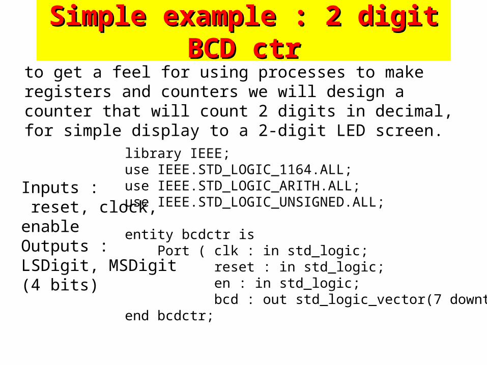
Simple example : 2 digit BCD ctrSimple example : 2 digit BCD ctrto get a feel for using processes to make registers and counters we will design a counter that will count 2 digits in decimal, for simple display to a 2-digit LED screen.
Inputs : reset, clock, enableOutputs : LSDigit, MSDigit (4 bits)
library IEEE;use IEEE.STD_LOGIC_1164.ALL;use IEEE.STD_LOGIC_ARITH.ALL;use IEEE.STD_LOGIC_UNSIGNED.ALL;
entity bcdctr is Port ( clk : in std_logic; reset : in std_logic; en : in std_logic; bcd : out std_logic_vector(7 downto 0));end bcdctr;
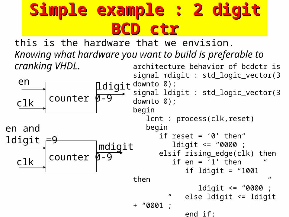
Simple example : 2 digit BCD ctrSimple example : 2 digit BCD ctrthis is the hardware that we envision. Knowing what hardware you want to build is preferable to cranking VHDL.
counter 0-9clk
en
counter 0-9clk
en and ldigit =9
ldigit
mdigit
architecture behavior of bcdctr issignal mdigit : std_logic_vector(3 downto 0);signal ldigit : std_logic_vector(3 downto 0);begin lcnt : process(clk,reset) begin if reset = ‘0’ then ldigit <= “0000”; elsif rising_edge(clk) then if en = ‘1’ then if ldigit = “1001” then ldigit <= “0000”; else ldigit <= ldigit + “0001”; end if; end if; end if; end process lcnt;
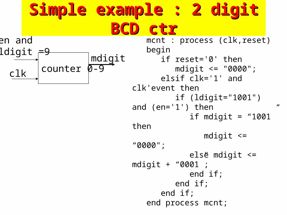
Simple example : 2 digit BCD ctrSimple example : 2 digit BCD ctr
counter 0-9clk
en and ldigit =9
mdigit
mcnt : process (clk,reset) begin if reset='0' then mdigit <= "0000"; elsif clk='1' and clk'event then if (ldigit="1001") and (en='1') then if mdigit = “1001” then mdigit <= “0000"; else mdigit <= mdigit + “0001”; end if; end if; end if; end process mcnt;
bcd(3 downto 0) <= ldigit; bcd(7 downto 4) <= mdigit;
end behavior;
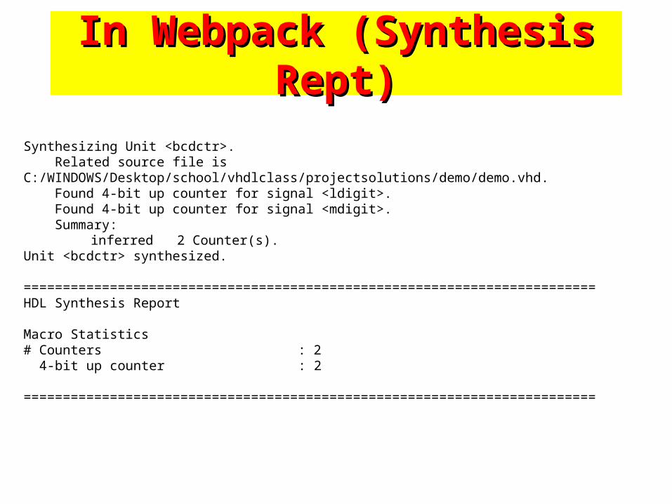
In Webpack (Synthesis Rept)In Webpack (Synthesis Rept)
Synthesizing Unit <bcdctr>. Related source file is C:/WINDOWS/Desktop/school/vhdlclass/projectsolutions/demo/demo.vhd. Found 4-bit up counter for signal <ldigit>. Found 4-bit up counter for signal <mdigit>. Summary:
inferred 2 Counter(s).Unit <bcdctr> synthesized.
=========================================================================HDL Synthesis Report
Macro Statistics# Counters : 2 4-bit up counter : 2
=========================================================================
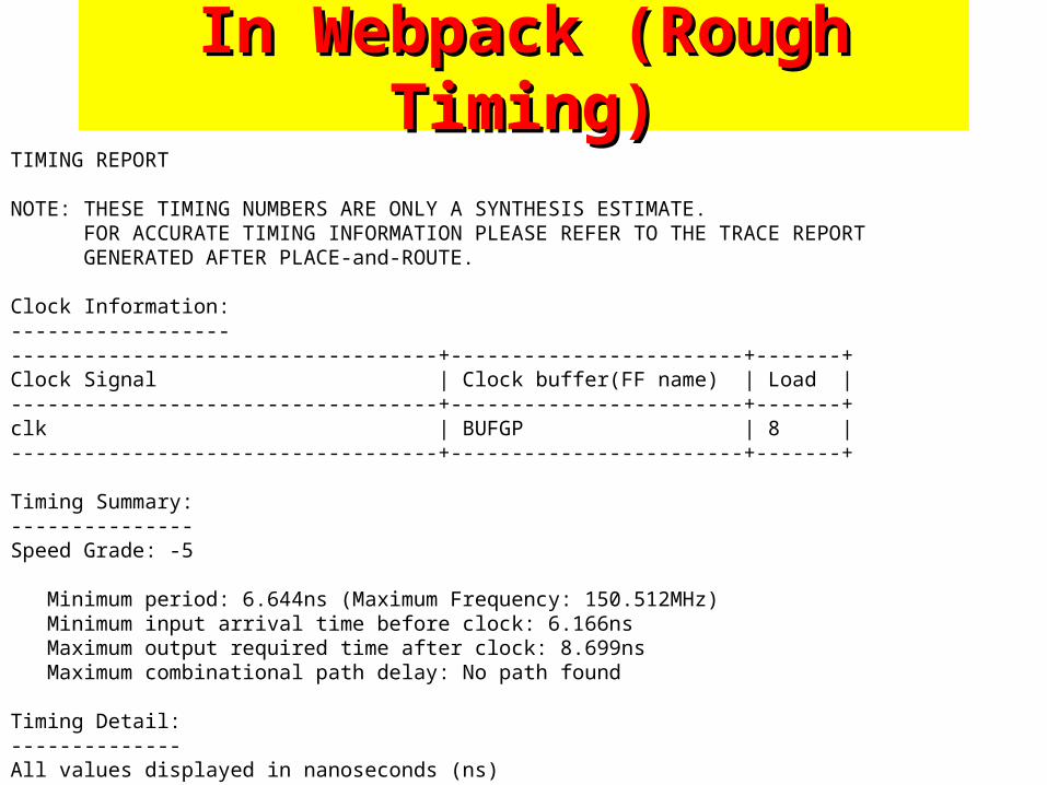
In Webpack (Rough Timing)In Webpack (Rough Timing)TIMING REPORT
NOTE: THESE TIMING NUMBERS ARE ONLY A SYNTHESIS ESTIMATE. FOR ACCURATE TIMING INFORMATION PLEASE REFER TO THE TRACE REPORT GENERATED AFTER PLACE-and-ROUTE.
Clock Information:-----------------------------------------------------+------------------------+-------+Clock Signal | Clock buffer(FF name) | Load |-----------------------------------+------------------------+-------+clk | BUFGP | 8 |-----------------------------------+------------------------+-------+
Timing Summary:---------------Speed Grade: -5
Minimum period: 6.644ns (Maximum Frequency: 150.512MHz) Minimum input arrival time before clock: 6.166ns Maximum output required time after clock: 8.699ns Maximum combinational path delay: No path found
Timing Detail:--------------All values displayed in nanoseconds (ns)
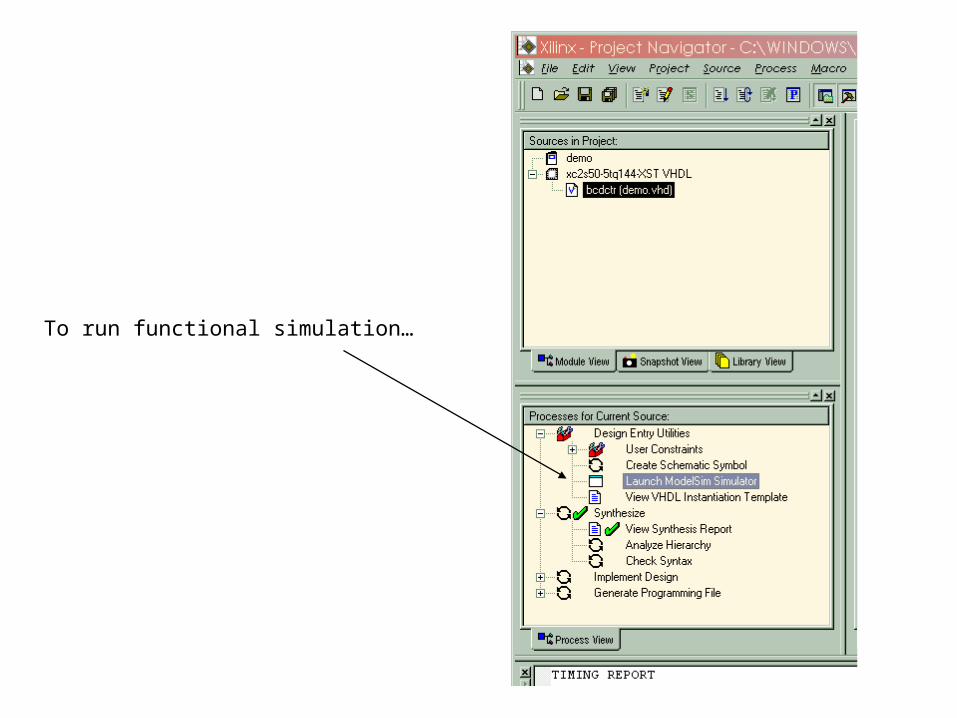
To run functional simulation…
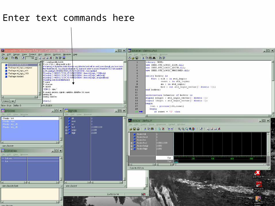
Enter text commands here
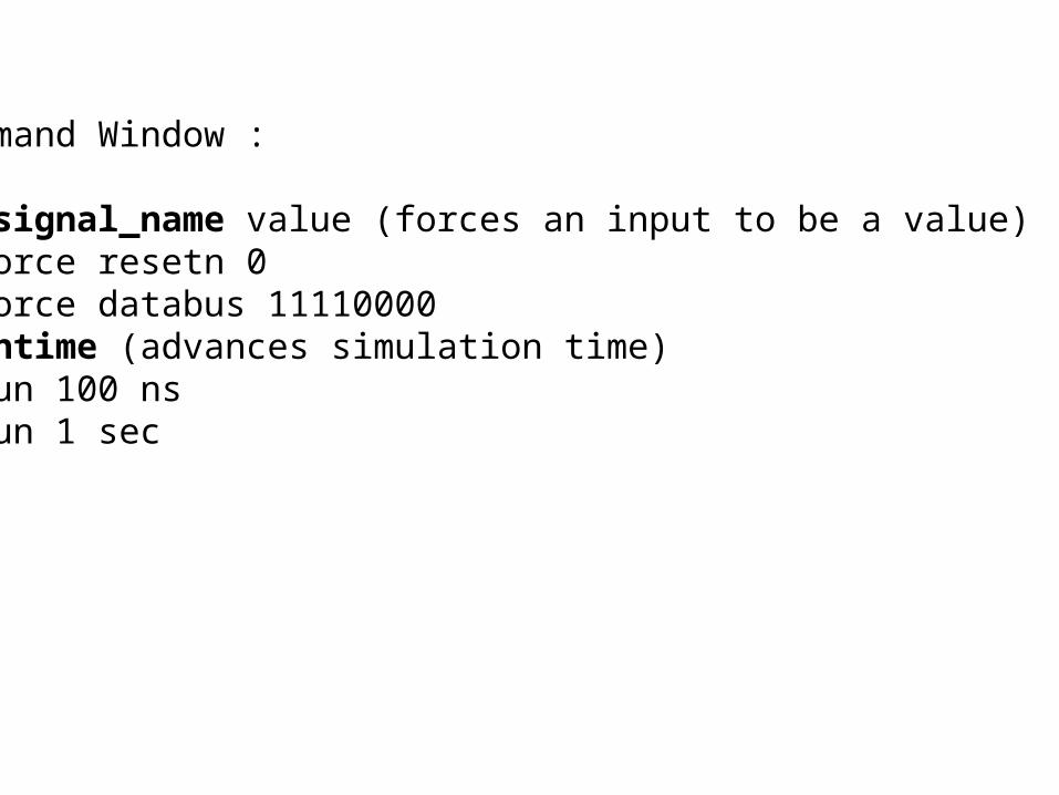
In Command Window :
force signal_name value (forces an input to be a value)force resetn 0force databus 11110000
run runtime (advances simulation time)run 100 nsrun 1 sec
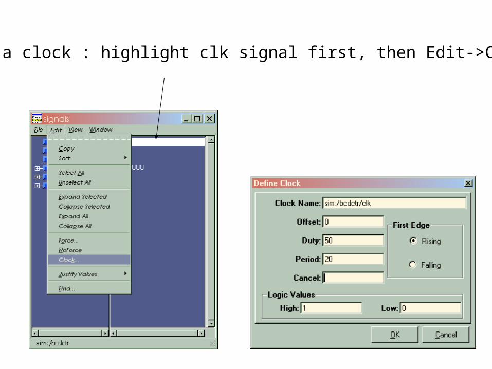
To force a clock : highlight clk signal first, then Edit->Clock
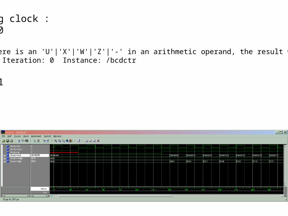
After forcing clock :force reset 0run 50# ** Warning: There is an 'U'|'X'|'W'|'Z'|'-' in an arithmetic operand, the result will be 'X'(es).# Time: 0 ps Iteration: 0 Instance: /bcdctr
force en 0force reset 1run 100force en 1run 200
Sequential VHDLSequential VHDLRushton Ch 8Rushton Ch 8
Processes
Ref : Ashenden Ch5, (for mechanics)
Edit->Languge Templates (in Webpack)