vfi course prerequisite manual
TRANSCRIPT
VFI COURSE
PREREQUISITE MANUAL The S&S engine class is designed for the seasoned tech or shop owner. A certain level of knowledge
and understanding is required for your success. We will be covering basic four stroke theory as
well as component identification. For many, this is going to be a review and refresher. However
it is necessary to help insure that all students are on a more even level.
Fuel injection basic theory
EFI Basics
• In its simplest terms, an electronic fuel injection (EFI) system is a computer controlled fuel
delivery system. This electronic control module (ECM) reads various sensors located on the
vehicle and makes the determination of how much fuel to allow the engine to have based
on this information. The computer will open and close the injectors allowing gasoline into
the engine based on the sensor inputs and the fuel Map programmed into the computer.
The various sensors (RPM, engine temperature, air temperature, throttle position, manifold
pressure, crankshaft position) provide information on operating conditions and load on the
engine.
• We will limit our discussion to the types of fuel injection systems that are likely to be
encountered on motorcycles. One of the major differences between fuel injection systems is
how they sense the amount of load that is placed on the engine. The load can be sensed by
how far the rider has twisted the throttle and Map (manifold absolute pressure). EFI
systems that sense engine load by the use of the throttle or TPS (throttle position sensor)
are referred to as an Alpha-N system. EFI systems that sense engine load by the use of a
Map sensor are referred to as a Speed-Density system. Harley-Davidson has used both types
of EFI systems on its vehicles
• While many of the sensors can be the same in both types of EFI systems, there is a
significant difference in the way that each system determines what the load on the engine
actually is. The Magneti Marelli system used on EVO and Twin Cam FLH's until 2001 and
Buell XL engines is an Alpha-N EFI system. On these bikes, load sensing is determined by the
throttle position. The newer Delphi EFI system used on current Twin Cam engines is a Speed
Density system. Speed Density EFI systems determine the engine load based on the intake
manifold vacuum.
Alpha-N
Strategy that bases fuel control on throttle angle (alpha) and RPM (N). The base fuel Map has
the throttle position on one axis and the rpm on the other axis. Each throttle angle and rpm
point will need a certain amount of fuel. Throttle position is also used for transients, idle and
WOT strategies.
i.e. - Harley Davidson Magneti Marelli EFI 1995-2001, S&S VFI, & other motorcycle systems.
Pro’s
Low Cost
Fast response for racing applications.
No intake manifold pressure sensing required.
Works well with high-overlap cam profiles that cause erratic intake manifold pressure.
Con’s
Engine to engine variability causes air/fuel ratio and drivability variability.
Minor engine changes require a different calibration.
Difficult to consistently meet emissions standards.
Speed/Density
Strategy that bases fuel control on engine speed (rpm) and intake manifold pressure (density).
By knowing the air pressure in the intake manifold/cylinder, the air temp and cylinder volume,
the mass of air can be calculated and the appropriate amount of fuel injected. The base fuel
Map will have intake manifold pressure on one axis and rpm on the other.
i.e. - Harley-Davidson Delphi EFI 2002- present, and OEM.
Pro’s
Reduced Air/Fuel ratio and drivability variability.
Minor engine changes do not require different calibrations.
Reduced exhaust emissions.
Con’s
Slightly slower response time.
Intake manifold pressure sensing required.
Increased development cost for accurate intake manifold pressure measurements.
Open Loop vs. Closed Loop
• Open Loop Systems: The ECM monitors sensors positioned on the intake side of the engine and
does not monitor the end result of internal combustion at the exhaust.
• Closed Loop Systems: The ECM monitors oxygen sensors (O2) positioned on the exhaust head
pipes. In closed loop the ECM controls the fuel mixture based on inputs from the very narrow
range of air/fuel ratio (AFR), the ECM can only control the mixture under cruising or very low
load conditions. Under all other conditions the ECM switched to open loop.
• NOTE: Both the closed and open loop systems can use Alpha-N, Speed/Density, or Mass-Air Flow
fuel strategies.
Part identification
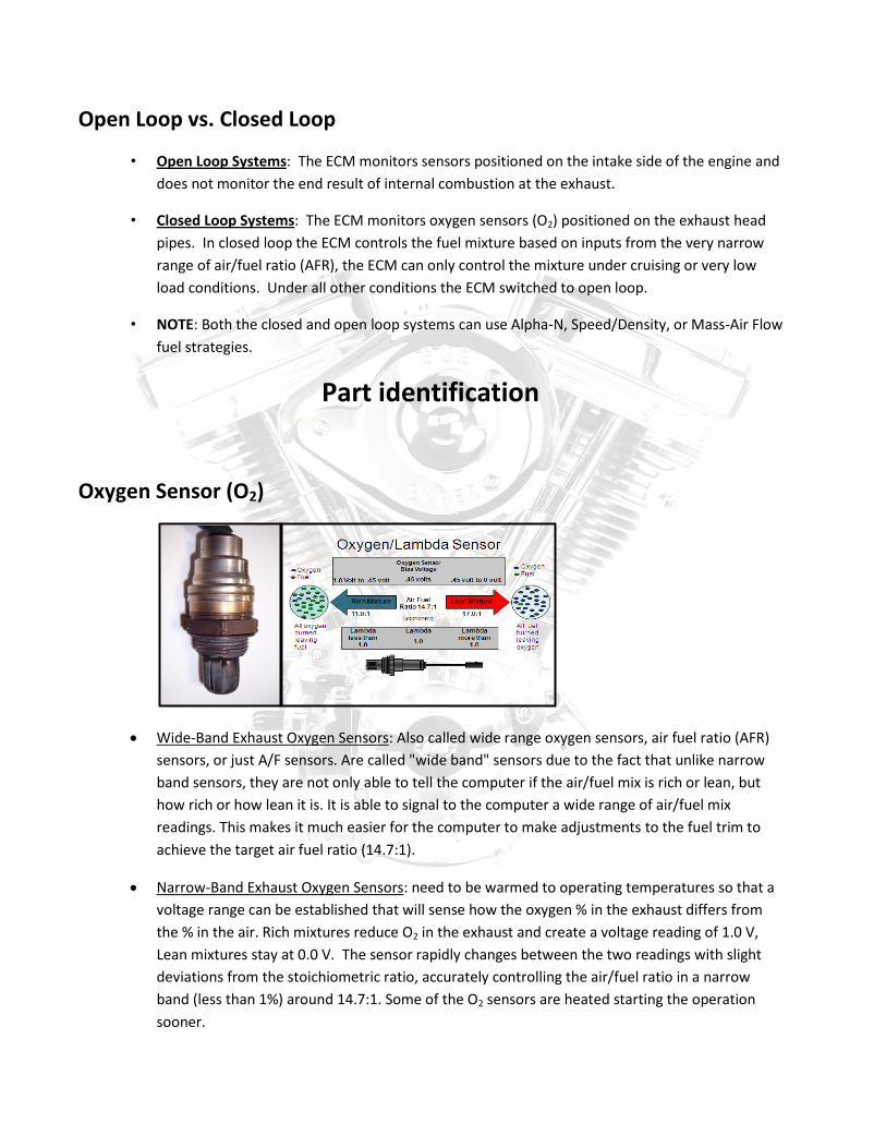
Oxygen Sensor (O2)
Wide-Band Exhaust Oxygen Sensors: Also called wide range oxygen sensors, air fuel ratio (AFR)
sensors, or just A/F sensors. Are called "wide band" sensors due to the fact that unlike narrow
band sensors, they are not only able to tell the computer if the air/fuel mix is rich or lean, but
how rich or how lean it is. It is able to signal to the computer a wide range of air/fuel mix
readings. This makes it much easier for the computer to make adjustments to the fuel trim to
achieve the target air fuel ratio (14.7:1).
Narrow-Band Exhaust Oxygen Sensors: need to be warmed to operating temperatures so that a
voltage range can be established that will sense how the oxygen % in the exhaust differs from
the % in the air. Rich mixtures reduce O2 in the exhaust and create a voltage reading of 1.0 V,
Lean mixtures stay at 0.0 V. The sensor rapidly changes between the two readings with slight
deviations from the stoichiometric ratio, accurately controlling the air/fuel ratio in a narrow
band (less than 1%) around 14.7:1. Some of the O2 sensors are heated starting the operation
sooner.
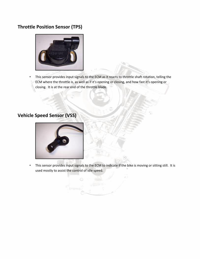
Throttle Position Sensor (TPS)
• This sensor provides input signals to the ECM as it reacts to throttle shaft rotation, telling the
ECM where the throttle is, as well as if it’s opening or closing, and how fast it’s opening or
closing. It is at the rear end of the throttle blade.
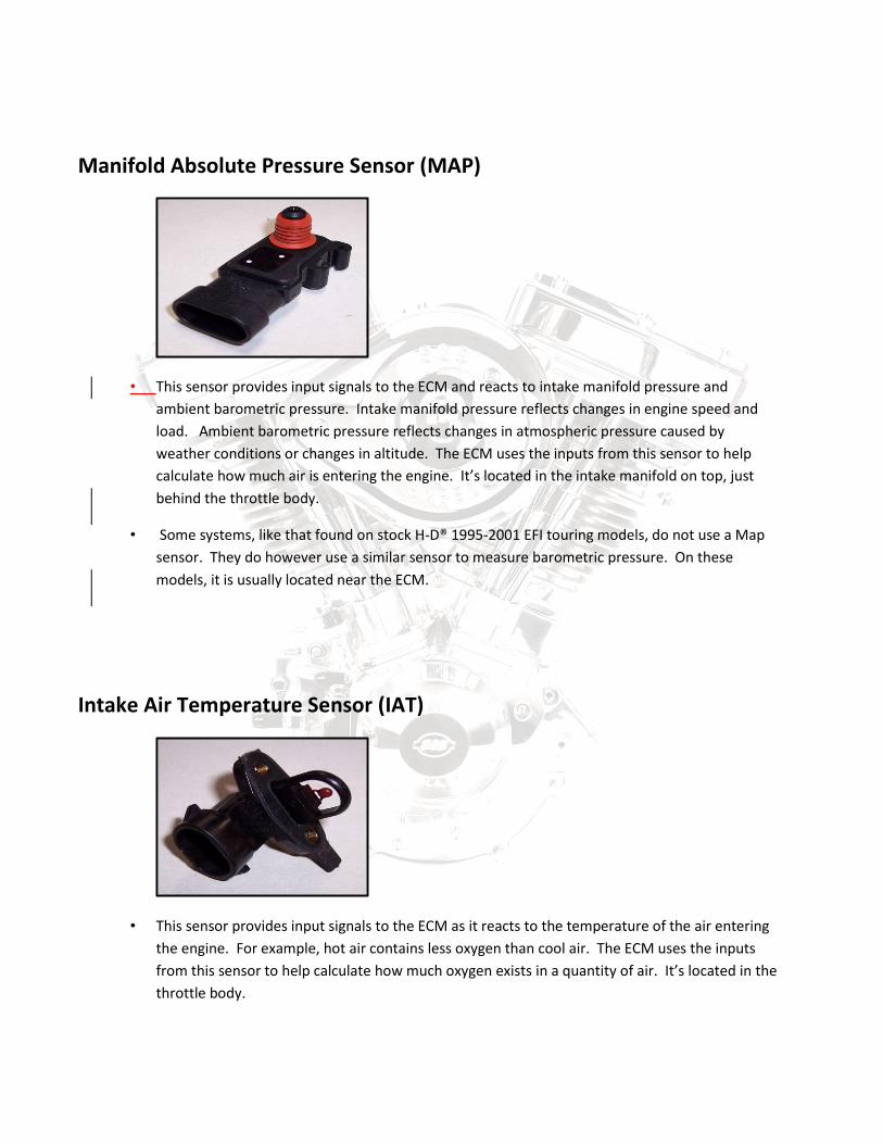
Vehicle Speed Sensor (VSS)
• This sensor provides input signals to the ECM to indicate if the bike is moving or sitting still. It is
used mostly to assist the control of idle speed.
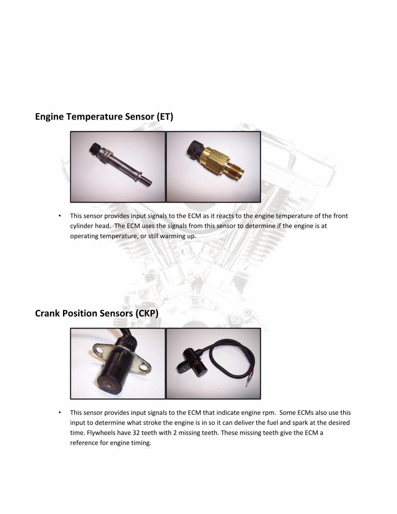
Manifold Absolute Pressure Sensor (MAP)
• This sensor provides input signals to the ECM and reacts to intake manifold pressure and
ambient barometric pressure. Intake manifold pressure reflects changes in engine speed and
load. Ambient barometric pressure reflects changes in atmospheric pressure caused by
weather conditions or changes in altitude. The ECM uses the inputs from this sensor to help
calculate how much air is entering the engine. It’s located in the intake manifold on top, just
behind the throttle body.
• Some systems, like that found on stock H-D® 1995-2001 EFI touring models, do not use a Map
sensor. They do however use a similar sensor to measure barometric pressure. On these
models, it is usually located near the ECM.
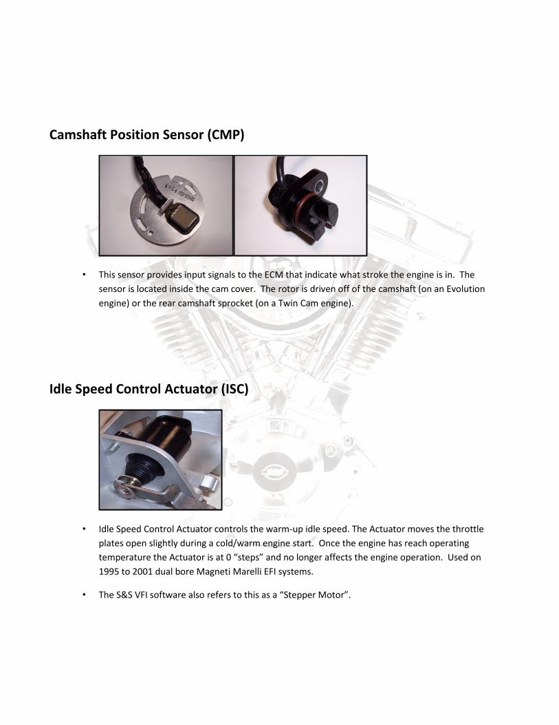
Intake Air Temperature Sensor (IAT)
• This sensor provides input signals to the ECM as it reacts to the temperature of the air entering
the engine. For example, hot air contains less oxygen than cool air. The ECM uses the inputs
from this sensor to help calculate how much oxygen exists in a quantity of air. It’s located in the
throttle body.
Engine Temperature Sensor (ET)
• This sensor provides input signals to the ECM as it reacts to the engine temperature of the front
cylinder head. The ECM uses the signals from this sensor to determine if the engine is at
operating temperature, or still warming up.
Crank Position Sensors (CKP)
• This sensor provides input signals to the ECM that indicate engine rpm. Some ECMs also use this
input to determine what stroke the engine is in so it can deliver the fuel and spark at the desired
time. Flywheels have 32 teeth with 2 missing teeth. These missing teeth give the ECM a
reference for engine timing.
Camshaft Position Sensor (CMP)
• This sensor provides input signals to the ECM that indicate what stroke the engine is in. The
sensor is located inside the cam cover. The rotor is driven off of the camshaft (on an Evolution
engine) or the rear camshaft sprocket (on a Twin Cam engine).
Idle Speed Control Actuator (ISC)
• Idle Speed Control Actuator controls the warm-up idle speed. The Actuator moves the throttle
plates open slightly during a cold/warm engine start. Once the engine has reach operating
temperature the Actuator is at 0 “steps” and no longer affects the engine operation. Used on
1995 to 2001 dual bore Magneti Marelli EFI systems.
• The S&S VFI software also refers to this as a “Stepper Motor”.
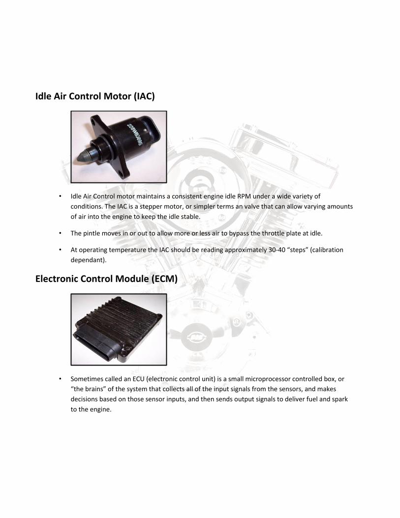
Idle Air Control Motor (IAC)
• Idle Air Control motor maintains a consistent engine idle RPM under a wide variety of
conditions. The IAC is a stepper motor, or simpler terms an valve that can allow varying amounts
of air into the engine to keep the idle stable.
• The pintle moves in or out to allow more or less air to bypass the throttle plate at idle.
• At operating temperature the IAC should be reading approximately 30-40 “steps” (calibration
dependant).
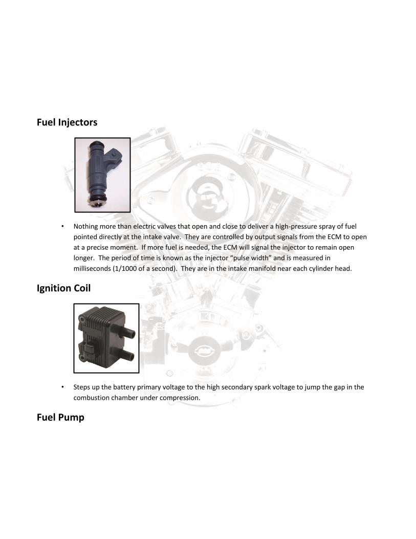
Electronic Control Module (ECM)
• Sometimes called an ECU (electronic control unit) is a small microprocessor controlled box, or
“the brains” of the system that collects all of the input signals from the sensors, and makes
decisions based on those sensor inputs, and then sends output signals to deliver fuel and spark
to the engine.
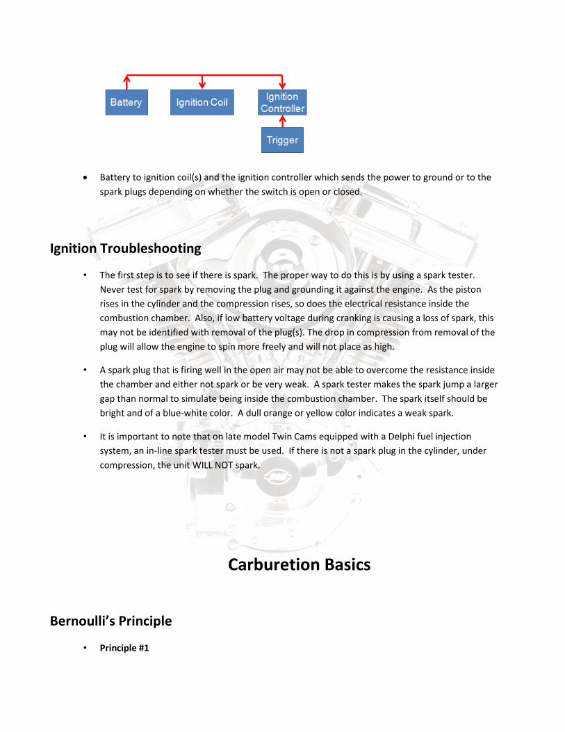
Fuel Injectors
• Nothing more than electric valves that open and close to deliver a high-pressure spray of fuel
pointed directly at the intake valve. They are controlled by output signals from the ECM to open
at a precise moment. If more fuel is needed, the ECM will signal the injector to remain open
longer. The period of time is known as the injector “pulse width” and is measured in
milliseconds (1/1000 of a second). They are in the intake manifold near each cylinder head.
Ignition Coil
• Steps up the battery primary voltage to the high secondary spark voltage to jump the gap in the
combustion chamber under compression.
Fuel Pump

• A 12-volt high pressure fuel pump, (located in the fuel tank) supplies fuel under pressure to the
fuel rail on the intake manifold. The fuel injectors will always have pressurized fuel ready and
waiting for the ECM command to open.
Ignition systems
Single fire
• In a single fire ignition, the power goes to the ignition coil and splits to saturate two separate
primary windings. Each of the primary coils goes to ground separately through the ignition
controller (ignition module or ECM). This way, the ignition can control the cylinders to fire
individually without there being a wasted spark
• A single fire coil can be set up to run with a digital ignition module. In this way, the ignition
timing for one, or both of the cylinders can be advanced or retarded depending on the inputs
that the ignition controller is receiving from the sensors on the motorcycle.
Dual fire
• In a dual fire ignition, the power goes to the primary side of the ignition coil. It travels through
the primary windings of the coil and then goes to ground through the ignition controller. The
ignition controller switches the ground to control the spark. The primary coil is already
saturated and the electromagnetic field has excited the windings of the secondary side.
• So when the ground is broken, the electricity finds its way to ground by jumping the spark plug
gap inside the combustion chamber. Both of the spark plugs fire at the same time. The cylinder
that is at TDCC will fire and start the power stroke.
• The spark in the other cylinder is wasted. When the ignition controller breaks the ground for the
other cylinder, again both spark plugs will fire. Combustion only occurs in one cylinder, and the
other spark is wasted.
Ignition basics
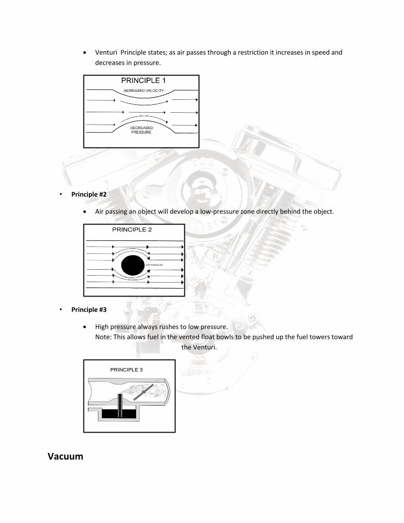
• The power flow goes like this:
Battery to ignition coil(s) and the ignition controller which sends the power to ground or to the
spark plugs depending on whether the switch is open or closed.
Ignition Troubleshooting
• The first step is to see if there is spark. The proper way to do this is by using a spark tester.
Never test for spark by removing the plug and grounding it against the engine. As the piston
rises in the cylinder and the compression rises, so does the electrical resistance inside the
combustion chamber. Also, if low battery voltage during cranking is causing a loss of spark, this
may not be identified with removal of the plug(s). The drop in compression from removal of the
plug will allow the engine to spin more freely and will not place as high.
• A spark plug that is firing well in the open air may not be able to overcome the resistance inside
the chamber and either not spark or be very weak. A spark tester makes the spark jump a larger
gap than normal to simulate being inside the combustion chamber. The spark itself should be
bright and of a blue-white color. A dull orange or yellow color indicates a weak spark.
• It is important to note that on late model Twin Cams equipped with a Delphi fuel injection
system, an in-line spark tester must be used. If there is not a spark plug in the cylinder, under
compression, the unit WILL NOT spark.
Carburetion Basics
Bernoulli’s Principle
• Principle #1
Venturi Principle states; as air passes through a restriction it increases in speed and
decreases in pressure.
• Principle #2
Air passing an object will develop a low-pressure zone directly behind the object.
• Principle #3
High pressure always rushes to low pressure.
Note: This allows fuel in the vented float bowls to be pushed up the fuel towers toward
the Venturi.
Vacuum
• A vacuum is an area where the air pressure is less than atmospheric pressure. It can create a
suction effect from an adjacent area of greater pressure. The air will move from the area of
greater pressure to an area of lower pressure, trying to equalize pressures.
Fuel mixtures
• Once the fuel is atomized and mixed with the air, it must be metered and delivered to the
cylinder in the right proportion.
• Stoichiometric efficiency refers to the ratio of air to fuel such that the most fuel possible is
delivered, but is still completely burned during the combustion process. The actual ratio will
vary slightly, but will stay close to 14.7 lbs of air to 1 lb of fuel.
• Rich Condition
If there is too much fuel in the mixture, it is said to be RICH. Typical symptoms of a rich
mixture are:
• Black smoke
• Black plugs
• Vibration
• Bucking
• Low power
• Poor fuel economy
• Rough, varying idle
• Wants to stall from idle
• Runs better cold
• Runs worse as warms up
• Lean Condition
If there is not enough fuel in the mixture, it is said to be LEAN. Typical symptoms of a
lean mixture are:
• White blistered plugs
• Dry hot exhaust
• Needs choke even warm
• Surging
• Low power
• Pipe bluing
• Change in fuel economy
• Racing, varying idle
• Won’t idle
• Hard starting (cold blooded)
• Runs better hot
• Pre-ignition / detonation / auto ignition
• At times, especially during startup when the engine is cold, the mixture can be temporarily
richened to enable easier starting of the motor. This is done in one of two ways:
CHOKE - limits the amount of air available to the motor.
ENRICHENER - opens a path for more fuel to enter the throat of the carb.
• In either case, It should be used only as long as necessary to keep the motor running, until just
actuation of the throttle is able to keep it going until a smooth idle is achieved.
• An ACCELERATOR PUMP adds a quick shot of fuel to the mixture when the throttle is opened to
aid in pickup until the rest of the carburetor circuits catch up.
Important Terms
• ATDC (After Top Dead Center) - The area in the crank rotation after TDC but less than halfway
to BDC.
• BDC (Bottom Dead Center) - The spot in the pistons movement when the piston is at the lowest
point in the cylinder.
• BBDC (Before Bottom Dead Center) - The area in the crank rotation approaching BDC.
• ABDC (After Bottom Dead Center) - The area in the crank rotation after the piston passes BDC
but less than half way to TDC.
• Advance - Term referring to adjusting the timing of the ignition to fire the plug earlier, before
the piston reaches TDC.
• Advance curve - A collective set of points that determine how far advanced or retarded the
timing will be under given engine operating conditions.
• Retard - Term referring to timing the ignition to fire closer to the piston reaching TDC.
• TDC (Top Dead Center) - The time in a pistons movement when the piston is at the very top of
its motion. Each cylinder has its own TDC within the rotation of the crank.
• TDCC (Top Dead Center Compression) - TDC on the compression stroke for the cylinder.
• BTDC (Before Top Dead Center) - The area in the crank rotation approaching TDC but more
than halfway past BDC.