vertical 2 stage jet monoblock - aqua groupvertical 2 stage jet monoblock the vertical 2 stage jet...
TRANSCRIPT
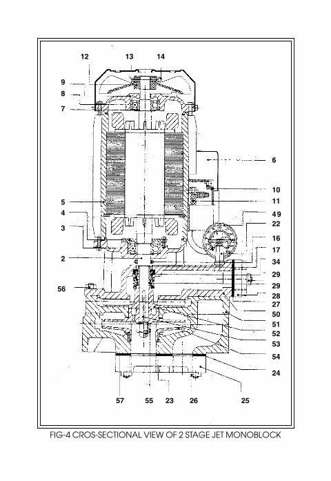
VERTICAL 2 STAGE JET MONOBLOCK
BRIEF DESCRIPTION OF THE
VERTICAL 2 STAGE JET MONOBLOCK
The Vertical 2 Stage Jet Monoblock consists of a monoblock
and a jet unit which operate in combination to pump water from
deep wells. Water is forced under pressure through a nozzle and a
venturi. The water surrounding the nozzle area is trapped along
with the high speed stream and in this way water is pumped out.
Therefore two pipes are required to be inserted into the well-one for
injecting water into the well and one for bringing the water out of
the well.
CHECKS TO BE MADE BEFORE INSTALLATION
1) The diameter of the borewell should be checked before
lowering the jet unit and pipes into the borewell. This check will
ensure that the jet unit does not get struck in the bore at any
point. The check is carried out using a disc whose diameter is
equal to the maximum diameter of the jet unit.
2) Measurements are also to be made of the following quantities.
a) Depth of the well from ground level.
b) Yield of borewell. This is a measure of the maximum amount of
water that can continuously be drawn from the well while
maintaining a stable water level. Borewell operators can
measure this quantity by a compressor test.
c) Lowest water level. In summer the water level will go down and
therefore this should be taken into account.
INSTALLATION
1) The Vertical 2 Stage Jet Monoblock should be installed in a
clean, dry location with proper ventilation. Do not install in
open air without sufficient covering.
2) The Monoblock can be installed either close to the well or
away from it. The pipes leading from the Monoblock to the well
must slope down form the monoblock to the well. A slope of 1 in
50 is sufficient.
3) Only new GI or PVC or HDPE pipes and fittings are to be used.
Old pipes contain loose scale and dirt and these will block the
nozzle and put the pump out of order.
4) The Jet unit should be located around 3 meters (10 feet) above
the lowest water level in the borewell.
5) EQUIPMENT REQUIRED
Hoist, tripod, pipe clamps and wrenches are required. A good
threading compound is to be used.
6) At every joint good threading compound is to be applied to
ensure a leak-proof joint.
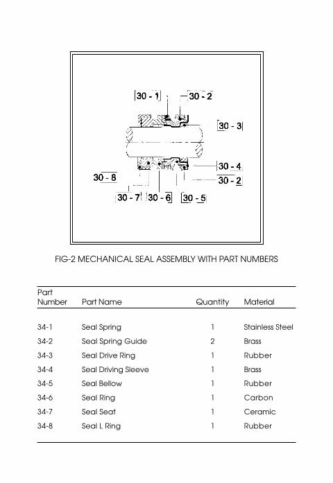
Note : The 2 Stage Jet pump will not function even if there is a
slight leak in the suction pipe.
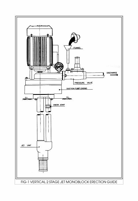
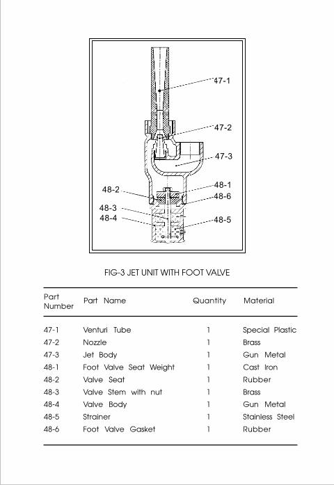
7) The pressure pipe is to be connected between the elbow and
flange using a union as shown in figure 1.
8) For ease in priming the pump, a ‘Tee’ fitting is to be connected
on the delivery side as shown in figure.
1. The ‘Tee’ fitting should be located between the flange and
pressure valve, not after the pressure valve, since the
pressure valve is a one way valve.
9) Minimum 3/20 wire to be used for supply leads.
OPERATION
1) Priming
When the pump is started for the first time it is to be primed (i.e.
the pump is to be filled with water). This can be accomplished
using the ‘Tee’ fitting as shown in figure-1. The aircock is
opened. Water is poured until there is a free flow from the
a i r c o c k . T h e n t h e a i r c o c k i s c l o s e d
gradually while water is being poured. If after closing the
aircock the water level in the ‘Tee’ fitting falls, this indicates
there is a leak and a mechanic should be consulted.
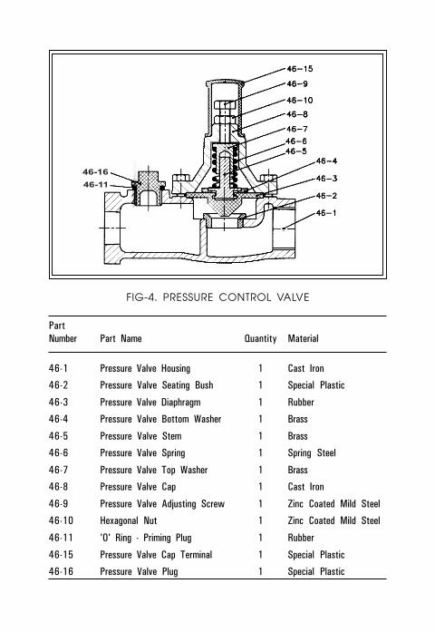
2) Setting of Pressure Control valve for maximum discharge
The most convenient method of setting the control valve for
optimum results is the visual method. In this method the
p u m p s e t i s r u n a n d t h e a d j u s t i n g s c r e w
(Part No. 46-11) is set such that the flow of water is maximum.
In order to set the adjusting screw, the pressure valve cap
Terminal (Part No. 46-12) is to be removed and refitted after
adjustment to prevent tampering.
3) Caution
Pumped water must not contain sand or grit. In a new
borewell there will be sand, mud, girt etc, as a result of the
drilling of the borewell. While starting for the first time the
pump is not to be stopped until clear water flows i.e. it must
not be switched off while pumping sandy water.
4) Common Problems & Remedies :
a. Discharge drops due to low yield of borewell,
In this case the adjustment screw of the pressure control
valve is to be set that discharge is limited.
b. Motor gets overheated due to :-
(i) Undervoltage
(ii) Voltage drop in supply leads due to use of undersize wires.
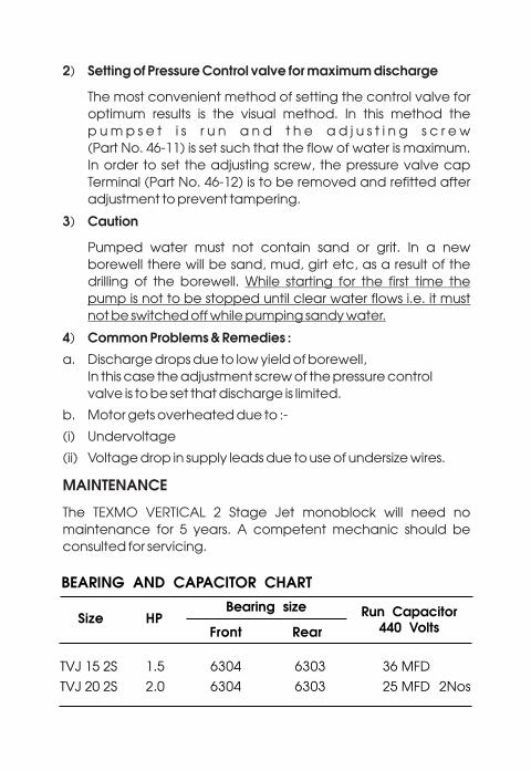
MAINTENANCE
The TEXMO VERTICAL 2 Stage Jet monoblock will need no
maintenance for 5 years. A competent mechanic should be
consulted for servicing.
46-16
46-11
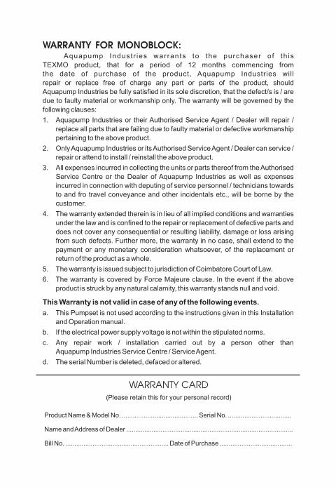
WARRANTY FOR MONOBLOCK:Aquapump Indust r ies warrants to the purchaser o f th is
TEXMO product, that for a period of 12 months commencing from
the date of purchase of the product, Aquapump Industries will
repair or replace free of charge any part or parts of the product, should
Aquapump Industries be fully satisfied in its sole discretion, that the defect/s is / are
due to faulty material or workmanship only. The warranty will be governed by the
following clauses:
1. Aquapump Industries or their Authorised Service Agent / Dealer will repair /
replace all parts that are failing due to faulty material or defective workmanship
pertaining to the above product.
2. Only Aquapump Industries or its Authorised Service Agent / Dealer can service /
repair or attend to install / reinstall the above product.
3. All expenses incurred in collecting the units or parts thereof from the Authorised
Service Centre or the Dealer of Aquapump Industries as well as expenses
incurred in connection with deputing of service personnel / technicians towards
to and fro travel conveyance and other incidentals etc., will be borne by the
customer.
4. The warranty extended therein is in lieu of all implied conditions and warranties
under the law and is confined to the repair or replacement of defective parts and
does not cover any consequential or resulting liability, damage or loss arising
from such defects. Further more, the warranty in no case, shall extend to the
payment or any monetary consideration whatsoever, of the replacement or
return of the product as a whole.
5. The warranty is issued subject to jurisdiction of Coimbatore Court of Law.
6. The warranty is covered by Force Majeure clause. In the event if the above
product is struck by any natural calamity, this warranty stands null and void.
This Warranty is not valid in case of any of the following events.
a. This Pumpset is not used according to the instructions given in this Installation
and Operation manual.
b. If the electrical power supply voltage is not within the stipulated norms.
c. Any repair work / installation carried out by a person other than
Aquapump Industries Service Centre / Service Agent.
d. The serial Number is deleted, defaced or altered.
WARRANTY CARD(Please retain this for your personal record)
Product Name & Model No. .......................................... Serial No. ...................................
Name and Address of Dealer ............................................................................................
Bill No. ......................................................... Date of Purchase ........................................