verilog fsm design example - heriot-watt · pdf fileverilog fsm design example ... verilog fsm...
TRANSCRIPT

Logic Design :Verilog FSM in class design example s 1 S. Yoder ND, 2010
CSE 20221: Logic Design
Verilog FSM Design Example
Automatic Garage Door Opener&
Timers

Logic Design :Verilog FSM in class design example s 2 S. Yoder ND, 2010
Inputs / Outputs
Define the module interface
NAME TYPE FUNCTION
activate (A) input starts the door to go up or down or stops the motion
Up_limit (UPL) input indicates maximum upward travel
Dn_limit (DNL) input indicates maximum downward travel
Motor_up (MU) output Causes motor to run in direction to raise the door
Motor_dn (MD) output Causes motor to run in direction to lower door

Logic Design :Verilog FSM in class design example s 3 S. Yoder ND, 2010
Inputs / Outputs
NAME TYPE FUNCTION
activate (A) input starts the door to go up or down or stops the motion
Up_limit (UPL) input indicates maximum upward travel
Dn_limit (DNL) input indicates maximum downward travel
Motor_up (MU) output Causes motor to run in direction to raise the door
Motor_dn (MD) output Causes motor to run in direction to lower door
reset input Force the controller to enter into the initial state

Logic Design :Verilog FSM in class design example s 4 S. Yoder ND, 2010
State Diagram
initial
upnext
dnnext
movingup
movingdown
A
UPL
A
DNL
AMU MD
UPLUPL’
A’A’
A’ ∙DNL’
A’ ∙DNL’

Logic Design :Verilog FSM in class design example s 5 S. Yoder ND, 2010
Make the State Assignments
initial
upnext
dnnext
movingup
movingdown
A
UPL
A
DNL
AMU MD
UPL
UPL’A’ A’
A’ ∙DNL’
A’ ∙DNL’
Logic Design :Verilog FSM in class design example s 6 S. Yoder ND, 2010
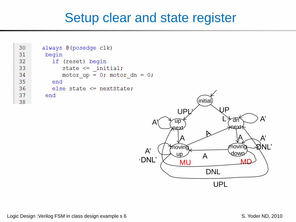
Setup clear and state register
initial
upnext
dnnext
movingup
movingdown
A
UPL
A
DNL
AMU MD
UPL
UPL’A’ A’
A’ ∙DNL’
A’ ∙DNL’

Logic Design :Verilog FSM in class design example s 7 S. Yoder ND, 2010
Describe the Behavior

Logic Design :Verilog FSM in class design example s 8 S. Yoder ND, 2010
Behavior Continued

Logic Design :Verilog FSM in class design example s 9 S. Yoder ND, 2010
Xilinx Verilog Test Fixture
1
Logic Design :Verilog FSM in class design example s 10 S. Yoder ND, 2010
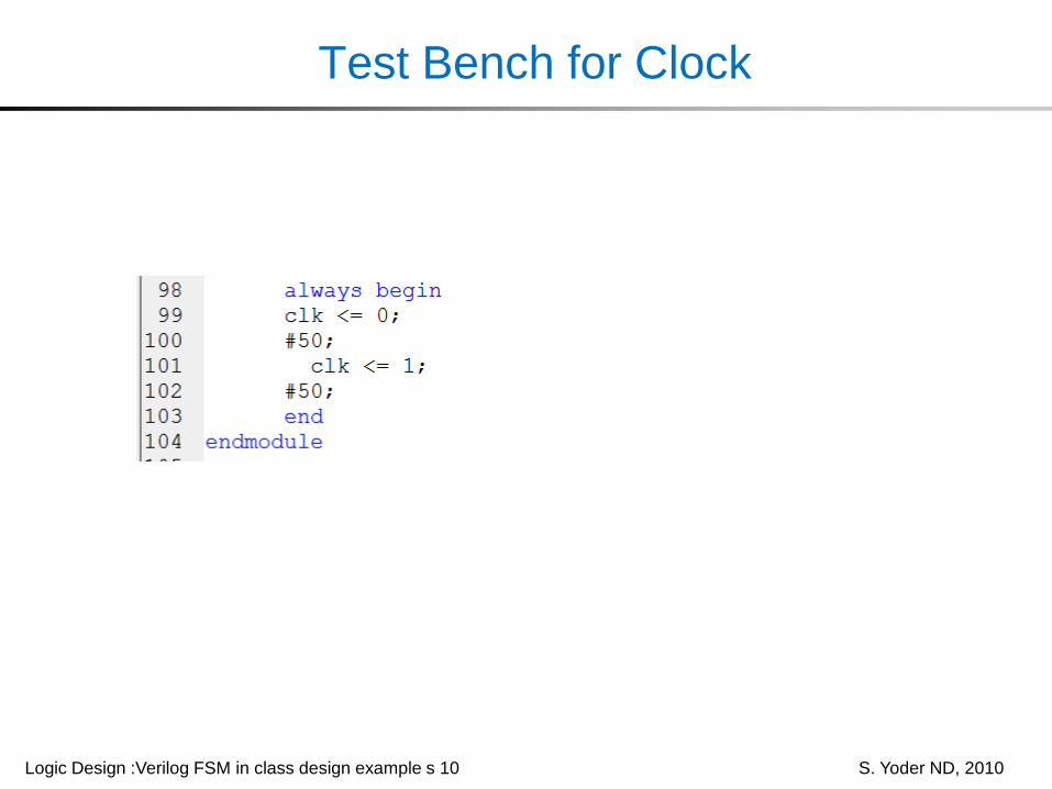
Test Bench for Clock

Logic Design :Verilog FSM in class design example s 11 S. Yoder ND, 2010
Simulation Results

Logic Design :Verilog FSM in class design example s 12 S. Yoder ND, 2010
Simulation Results Continued

Logic Design :Verilog FSM in class design example s 13 S. Yoder ND, 2010
Xilinx Simulation Tips
• Provide a means (reset signal) to initialize all internal variables, otherwise don’t care conditions occur throughout the simulation.
always @(posedge clk)begin
if (reset) begincountValue = 0;clkDivOut <= 0;
• In the test bench code, first initialize the circuit under test.• Select the sim instance tab in the source window to bring
up internal signals to be placed in the simulator waveform.

Logic Design :Verilog FSM in class design example s 14 S. Yoder ND, 2010
CSE 20221: Logic Design
Timers, Frequency Divider Examples

Logic Design :Verilog FSM in class design example s 15 S. Yoder ND, 2010
Timers
• Timer– time events– divide clock frequency– provide delay
• In each case the basic idea is to count clock pulses

Logic Design :Verilog FSM in class design example s 16 S. Yoder ND, 2010
Verilog Code for Timer

Logic Design :Verilog FSM in class design example s 17 S. Yoder ND, 2010
Timer Simulation

Logic Design :Verilog FSM in class design example s 18 S. Yoder ND, 2010
Verilog Code for Frequency Divider

Logic Design :Verilog FSM in class design example s 19 S. Yoder ND, 2010
Frequency Divider Simulation

Logic Design :Verilog FSM in class design example s 20 S. Yoder ND, 2010
Design of a Derived Clock
• Design a 1 millisecond clock that is derived from a 50 MHz system clock.
• Design approach– Frequency divider– Divide by 50,000
• Determining size (N) of counter– given division factor, DF– N = roundUp(ln DF / ln 2) -1– Parameter [N:0] countValue;

Logic Design :Verilog FSM in class design example s 21 S. Yoder ND, 2010
Verilog Description

Logic Design :Verilog FSM in class design example s 22 S. Yoder ND, 2010
Test Fixture

Logic Design :Verilog FSM in class design example s 23 S. Yoder ND, 2010
Similation Results