vehicle ride height chart - carid.com · this will prevent premature wear or failure of the bushing...
TRANSCRIPT
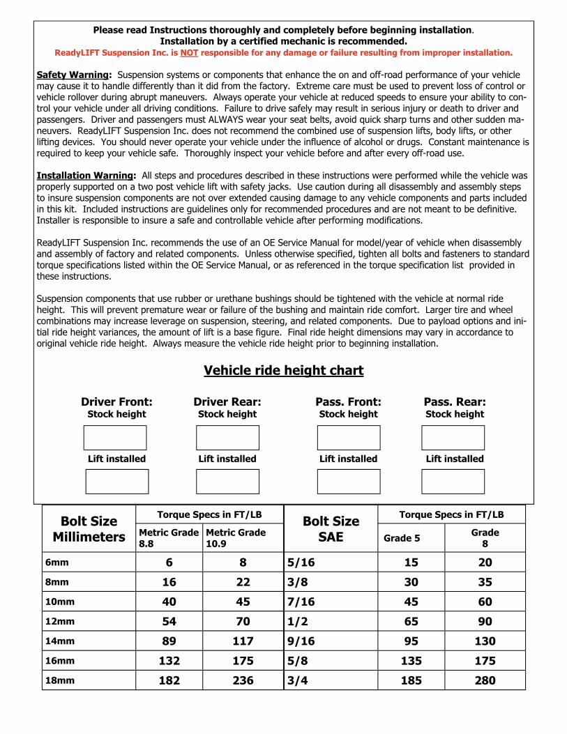
Bolt Size Millimeters
Torque Specs in FT/LB
Metric Grade 8.8
Metric Grade 10.9
6mm 6 8
8mm 16 22
10mm 40 45
12mm 54 70
14mm 89 117
16mm 132 175
18mm 182 236
Bolt Size SAE
Torque Specs in FT/LB
Grade 5 Grade 8
5/16 15 20
3/8 30 35
7/16 45 60
1/2 65 90
9/16 95 130
5/8 135 175
3/4 185 280
Please read Instructions thoroughly and completely before beginning installation. Installation by a certified mechanic is recommended.
ReadyLIFT Suspension Inc. is NOT responsible for any damage or failure resulting from improper installation.
Safety Warning: Suspension systems or components that enhance the on and off-road performance of your vehicle may cause it to handle differently than it did from the factory. Extreme care must be used to prevent loss of control or vehicle rollover during abrupt maneuvers. Always operate your vehicle at reduced speeds to ensure your ability to con-trol your vehicle under all driving conditions. Failure to drive safely may result in serious injury or death to driver and passengers. Driver and passengers must ALWAYS wear your seat belts, avoid quick sharp turns and other sudden ma-neuvers. ReadyLIFT Suspension Inc. does not recommend the combined use of suspension lifts, body lifts, or other lifting devices. You should never operate your vehicle under the influence of alcohol or drugs. Constant maintenance is required to keep your vehicle safe. Thoroughly inspect your vehicle before and after every off-road use. Installation Warning: All steps and procedures described in these instructions were performed while the vehicle was properly supported on a two post vehicle lift with safety jacks. Use caution during all disassembly and assembly steps to insure suspension components are not over extended causing damage to any vehicle components and parts included in this kit. Included instructions are guidelines only for recommended procedures and are not meant to be definitive. Installer is responsible to insure a safe and controllable vehicle after performing modifications. ReadyLIFT Suspension Inc. recommends the use of an OE Service Manual for model/year of vehicle when disassembly and assembly of factory and related components. Unless otherwise specified, tighten all bolts and fasteners to standard torque specifications listed within the OE Service Manual, or as referenced in the torque specification list provided in these instructions. Suspension components that use rubber or urethane bushings should be tightened with the vehicle at normal ride height. This will prevent premature wear or failure of the bushing and maintain ride comfort. Larger tire and wheel combinations may increase leverage on suspension, steering, and related components. Due to payload options and ini-tial ride height variances, the amount of lift is a base figure. Final ride height dimensions may vary in accordance to original vehicle ride height. Always measure the vehicle ride height prior to beginning installation.
Vehicle ride height chart
Driver Front: Stock height
Lift installed
Driver Rear: Stock height
Lift installed
Pass. Front: Stock height
Lift installed
Pass. Rear: Stock height
Lift installed
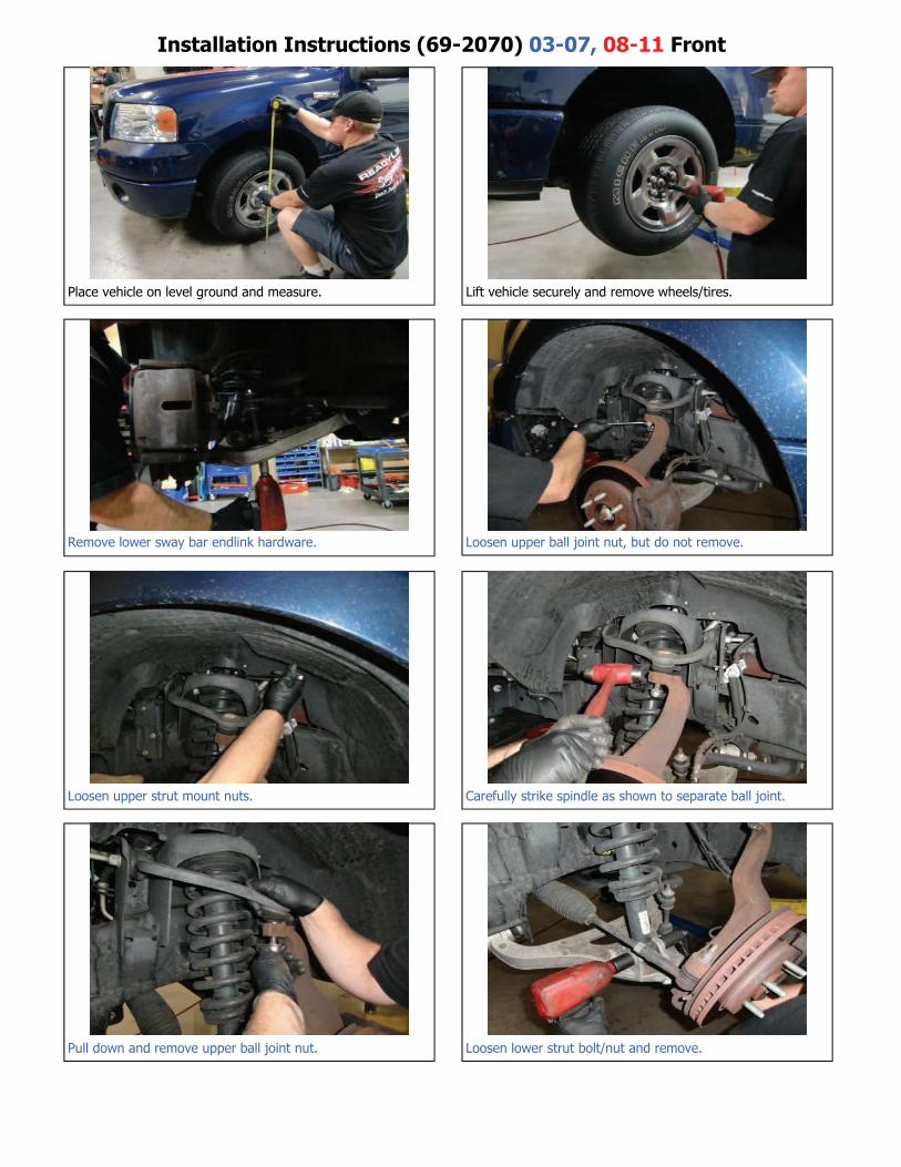
Installation Instructions (69-2070) 03-07, 08-11 Front
Place vehicle on level ground and measure. Lift vehicle securely and remove wheels/tires.
Remove lower sway bar endlink hardware. Loosen upper ball joint nut, but do not remove.
Loosen upper strut mount nuts. Carefully strike spindle as shown to separate ball joint.
Pull down and remove upper ball joint nut. Loosen lower strut bolt/nut and remove.
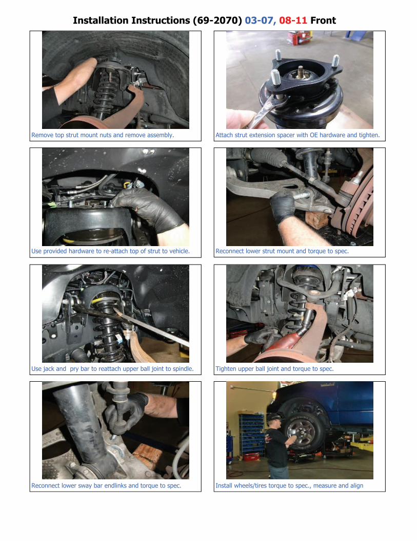
Installation Instructions (69-2070) 03-07, 08-11 Front
Remove top strut mount nuts and remove assembly. Attach strut extension spacer with OE hardware and tighten.
Use provided hardware to re-attach top of strut to vehicle. Reconnect lower strut mount and torque to spec.
Use jack and pry bar to reattach upper ball joint to spindle. Tighten upper ball joint and torque to spec.
Reconnect lower sway bar endlinks and torque to spec. Install wheels/tires torque to spec., measure and align
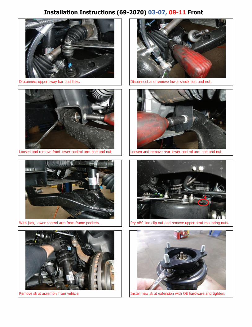
Installation Instructions (69-2070) 03-07, 08-11 Front
Disconnect upper sway bar end links. Disconnect and remove lower shock bolt and nut.
Loosen and remove front lower control arm bolt and nut Loosen and remove rear lower control arm bolt and nut.
With jack, lower control arm from frame pockets. Pry ABS line clip out and remove upper strut mounting nuts.
Remove strut assembly from vehicle Install new strut extension with OE hardware and tighten.
Make sure to replace ABS wiring clips onto top of strut mounting studs. Re-
connect sway bar end links and reinstall front wheels/tires.
Note: Rear Installation Instructions on the following pages
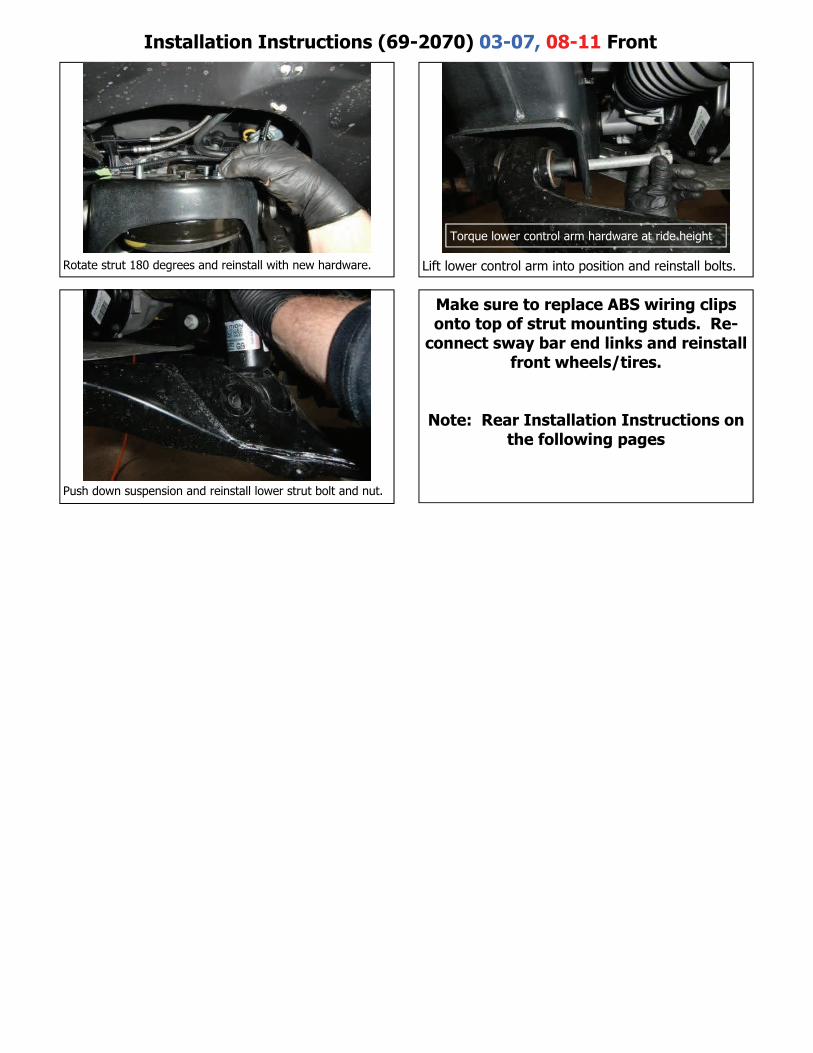
Installation Instructions (69-2070) 03-07, 08-11 Front
Rotate strut 180 degrees and reinstall with new hardware. Lift lower control arm into position and reinstall bolts.
Push down suspension and reinstall lower strut bolt and nut.
Torque lower control arm hardware at ride height
Note: It may be necessary to loosen the upper and lower control arms at the frame pivots in order to ease reinstalla-tion of strut assembly. If this is the case make sure to re-torque these bolts at ride height with vehicle on ground. Reinstall wheels/tires and torque. Re-check all work performed and test drive vehicle. Have vehicle aligned.
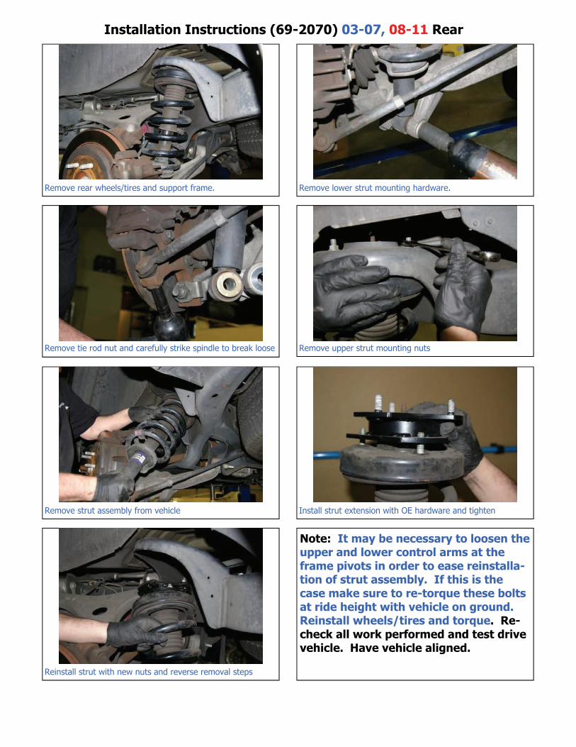
Installation Instructions (69-2070) 03-07, 08-11 Rear
Remove rear wheels/tires and support frame. Remove lower strut mounting hardware.
Remove tie rod nut and carefully strike spindle to break loose Remove upper strut mounting nuts
Remove strut assembly from vehicle Install strut extension with OE hardware and tighten
Reinstall strut with new nuts and reverse removal steps
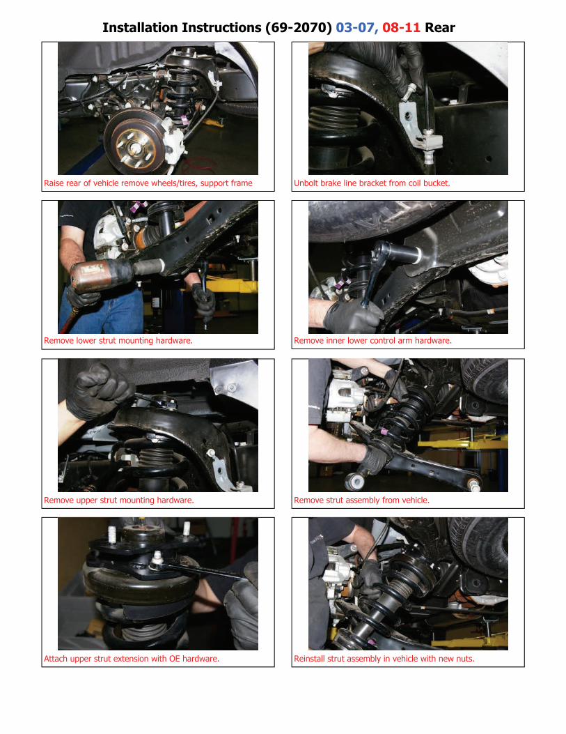
Installation Instructions (69-2070) 03-07, 08-11 Rear
Raise rear of vehicle remove wheels/tires, support frame Unbolt brake line bracket from coil bucket.
Remove lower strut mounting hardware. Remove inner lower control arm hardware.
Remove upper strut mounting hardware. Remove strut assembly from vehicle.
Attach upper strut extension with OE hardware. Reinstall strut assembly in vehicle with new nuts.
Next, reinstall wheels/tires lower to ground and torque. Then tighten lower strut mounting hardware and inner lower control arm hardware to spec. as shown in the next step.
Recheck all work performed before and after test drive and finally, have vehicle aligned.
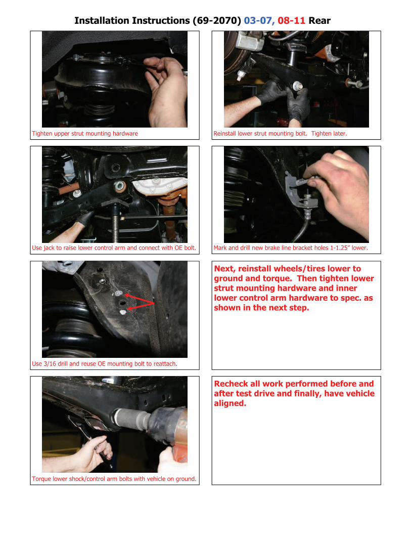
Installation Instructions (69-2070) 03-07, 08-11 Rear
Tighten upper strut mounting hardware Reinstall lower strut mounting bolt. Tighten later.
Use jack to raise lower control arm and connect with OE bolt. Mark and drill new brake line bracket holes 1-1.25” lower.
Use 3/16 drill and reuse OE mounting bolt to reattach.
Torque lower shock/control arm bolts with vehicle on ground.
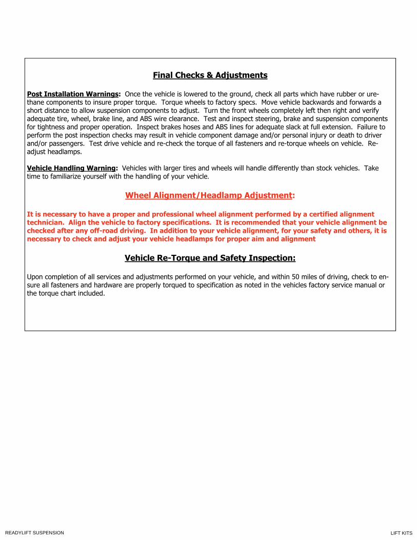
Final Checks & Adjustments
Post Installation Warnings: Once the vehicle is lowered to the ground, check all parts which have rubber or ure-thane components to insure proper torque. Torque wheels to factory specs. Move vehicle backwards and forwards a short distance to allow suspension components to adjust. Turn the front wheels completely left then right and verify adequate tire, wheel, brake line, and ABS wire clearance. Test and inspect steering, brake and suspension components for tightness and proper operation. Inspect brakes hoses and ABS lines for adequate slack at full extension. Failure to perform the post inspection checks may result in vehicle component damage and/or personal injury or death to driver and/or passengers. Test drive vehicle and re-check the torque of all fasteners and re-torque wheels on vehicle. Re-adjust headlamps. Vehicle Handling Warning: Vehicles with larger tires and wheels will handle differently than stock vehicles. Take time to familiarize yourself with the handling of your vehicle.
Wheel Alignment/Headlamp Adjustment:
It is necessary to have a proper and professional wheel alignment performed by a certified alignment technician. Align the vehicle to factory specifications. It is recommended that your vehicle alignment be checked after any off-road driving. In addition to your vehicle alignment, for your safety and others, it is necessary to check and adjust your vehicle headlamps for proper aim and alignment
Vehicle Re-Torque and Safety Inspection:
Upon completion of all services and adjustments performed on your vehicle, and within 50 miles of driving, check to en-sure all fasteners and hardware are properly torqued to specification as noted in the vehicles factory service manual or the torque chart included.
LIFT KITSREADYLIFT SUSPENSION