vehicle dynamics
TRANSCRIPT

1
Technical Seminar Series - Vehicle Dynamics August 2006
ArvinMeritor Quarterly Technical ArvinMeritor Quarterly Technical Seminar Series – Part IISeminar Series – Part II
Vehicle Dynamics Vehicle Dynamics
Troy Tech CenterJuly 31, 2006
2
Technical Seminar Series - Vehicle Dynamics August 2006
ObjectivesObjectives
• To introduce the basic concepts in vehicle dynamics, focusing on vehicle handling and stability
• To demonstrate the use of TruckSim software in simulating in the dynamics of trucks and tractor-semi-trailer combinations
• To identify the vehicle parameters that are pertinent to vehicle dynamics• Identify parameters required as inputs to TruckSim
• Propose improvements to standard laboratory tests
• To identify the vehicle tests and associated vehicle performance metrics used in assessing the handling performance of vehicles• Propose improvements to skid pad tests
3
Technical Seminar Series - Vehicle Dynamics August 2006
Presentation OutlinePresentation Outline
• Basic Tire Behavior
• Basics of Vehicle Dynamics: Steady-State Cornering
• Vehicle Tests for Handling Performance
• Using TruckSim to Simulate Vehicle Dynamics
• Inputs to TruckSim: Vehicle Parameters
• Examples of Using Simulation Results in Generating Vehicle Handling Performance Metrics

4
Technical Seminar Series - Vehicle Dynamics August 2006
Basic Tire BehaviorBasic Tire Behavior
5
Technical Seminar Series - Vehicle Dynamics August 2006
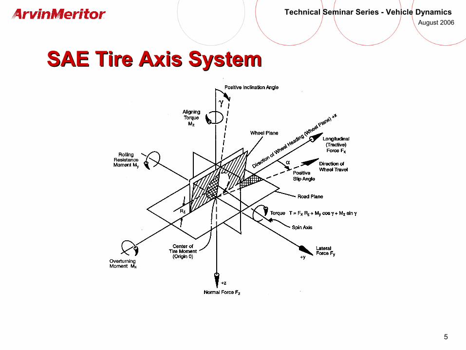
SAE Tire Axis SystemSAE Tire Axis System
6
Technical Seminar Series - Vehicle Dynamics August 2006
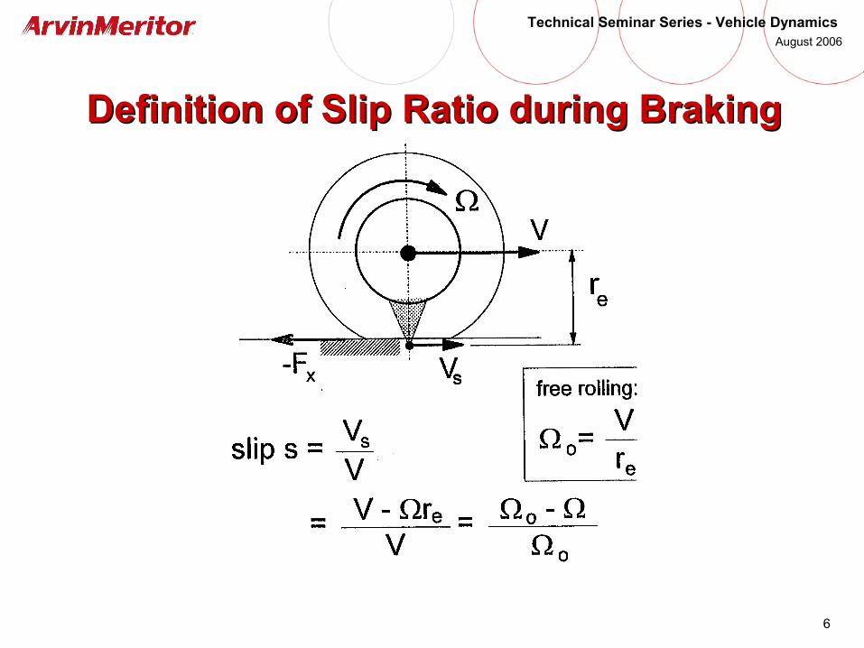
Definition of Slip Ratio during BrakingDefinition of Slip Ratio during Braking

7
Technical Seminar Series - Vehicle Dynamics August 2006
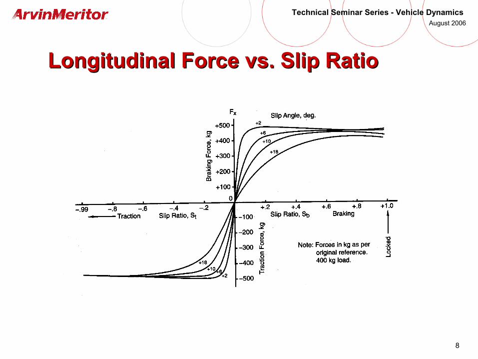
Generation of Longitudinal ForceGeneration of Longitudinal Force
8
Technical Seminar Series - Vehicle Dynamics August 2006
Longitudinal Force vs. Slip RatioLongitudinal Force vs. Slip Ratio
9
Technical Seminar Series - Vehicle Dynamics August 2006
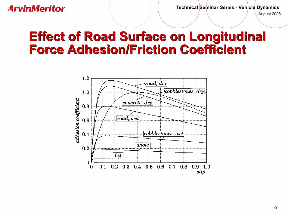
Effect of Road Surface on Longitudinal Effect of Road Surface on Longitudinal Force Adhesion/Friction CoefficientForce Adhesion/Friction Coefficient
10
Technical Seminar Series - Vehicle Dynamics August 2006
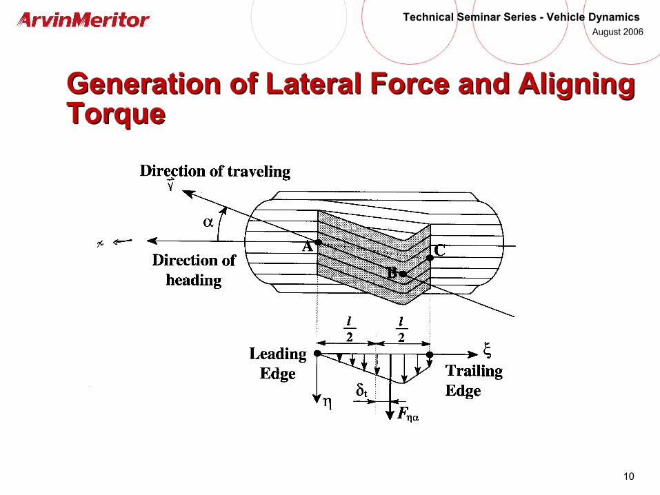
Generation of Lateral Force and Aligning Generation of Lateral Force and Aligning TorqueTorque
11
Technical Seminar Series - Vehicle Dynamics August 2006
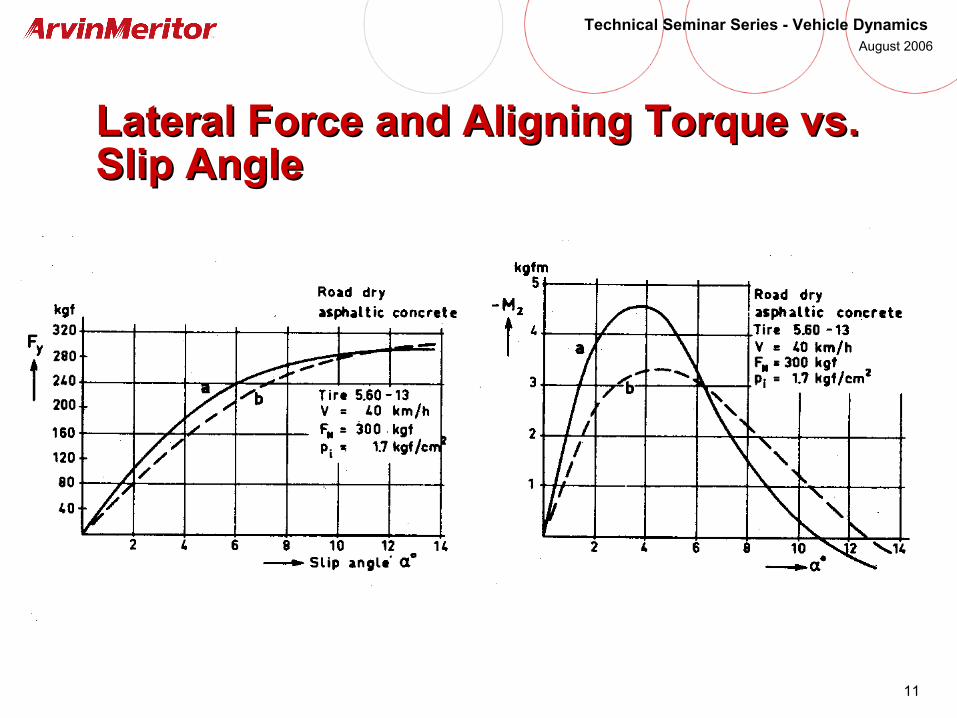
Lateral Force and Aligning Torque vs. Lateral Force and Aligning Torque vs. Slip AngleSlip Angle

12
Technical Seminar Series - Vehicle Dynamics August 2006
Comparing Cornering Force and Camber Comparing Cornering Force and Camber ThrustThrust
13
Technical Seminar Series - Vehicle Dynamics August 2006
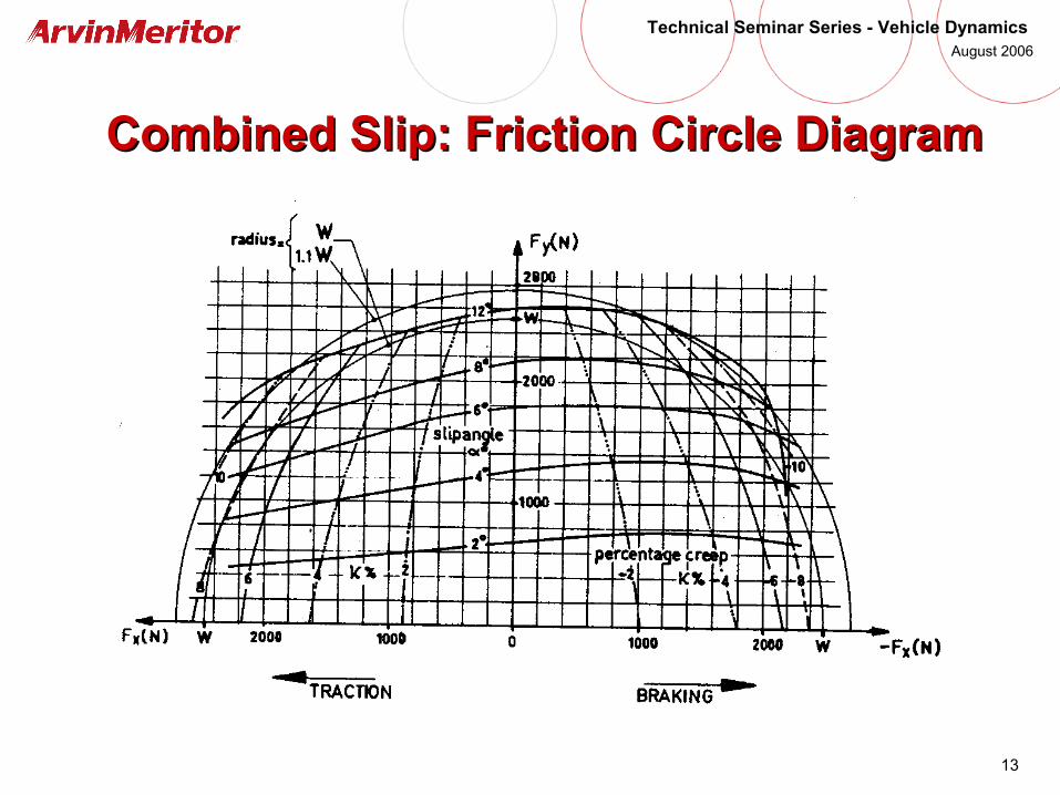
Combined Slip: Friction Circle DiagramCombined Slip: Friction Circle Diagram
14
Technical Seminar Series - Vehicle Dynamics August 2006
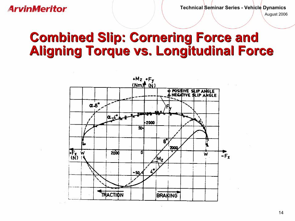
Combined Slip: Cornering Force and Combined Slip: Cornering Force and Aligning Torque vs. Longitudinal ForceAligning Torque vs. Longitudinal Force
15
Technical Seminar Series - Vehicle Dynamics August 2006
Factors Affecting Tire Forces and Factors Affecting Tire Forces and MomentsMoments
• Slip Ratio, Slip Angle, Inclination Angle
• Normal (Vertical) Force
• Road Surface
• Tire Inflation Pressure
• Speed of Travel
• Tire Wear
• Tread Pattern
• Tire Construction (Bias Ply vs. Radial Ply)

16
Technical Seminar Series - Vehicle Dynamics August 2006
Key Idea from Basic Tire Behavior: Key Idea from Basic Tire Behavior:
• Control of vehicle dynamics implies controlling the following 4 variables at each wheel:• Tire Slip Ratio
• Tire Slip Angle
• Tire Inclination Angle
• Tire Normal Force
• The above variables determine the friction forces between the tire and the ground
• How do we distribute the friction forces among all the wheels to get the desired vehicle behavior?
17
Technical Seminar Series - Vehicle Dynamics August 2006
Basics of Vehicle Dynamics: Basics of Vehicle Dynamics: Steady-State CorneringSteady-State Cornering

18
Technical Seminar Series - Vehicle Dynamics August 2006
SAE Vehicle Axis SystemSAE Vehicle Axis System
19
Technical Seminar Series - Vehicle Dynamics August 2006
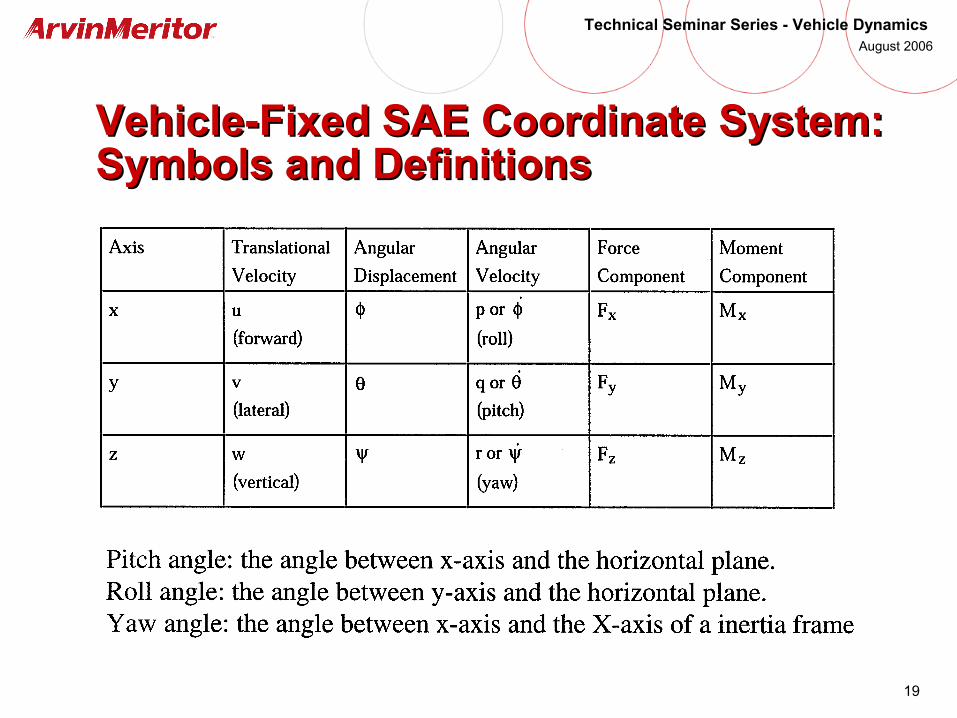
Vehicle-Fixed SAE CoordinateVehicle-Fixed SAE Coordinate System: System: Symbols and DefinitionsSymbols and Definitions
20
Technical Seminar Series - Vehicle Dynamics August 2006
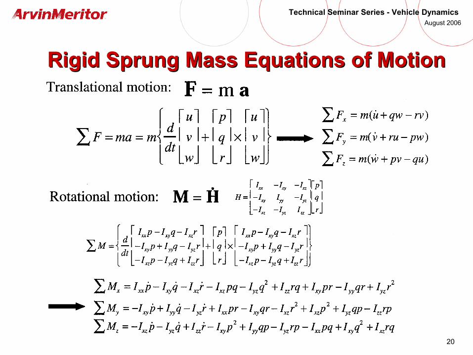
Rigid Sprung Mass Equations of MotionRigid Sprung Mass Equations of Motion

21
Technical Seminar Series - Vehicle Dynamics August 2006
Simplified Equations of MotionSimplified Equations of Motion of the of the Rigid Sprung Mass Rigid Sprung Mass
22
Technical Seminar Series - Vehicle Dynamics August 2006
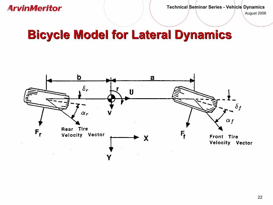
Bicycle Model for Lateral DynamicsBicycle Model for Lateral Dynamics

23
Technical Seminar Series - Vehicle Dynamics August 2006
Bicycle Model for Lateral DynamicsBicycle Model for Lateral Dynamics
• Assumptions• Constant forward velocity, u
• No suspension, no vehicle roll or pitch
• Front wheel steer angle is the average of LH and RH steer
• Motions are small perturbations from an initial trim condition
• All angles are small
• Roadway is flat and level
• Tire lateral forces are linear functions of tire slip angles
• Neglect tire aligning moment
• Neglect lateral load transfer
• Vehicle is symmetric with respect to x-z plane
• Consider only “fixed control” response, i.e., steer angle input
24
Technical Seminar Series - Vehicle Dynamics August 2006
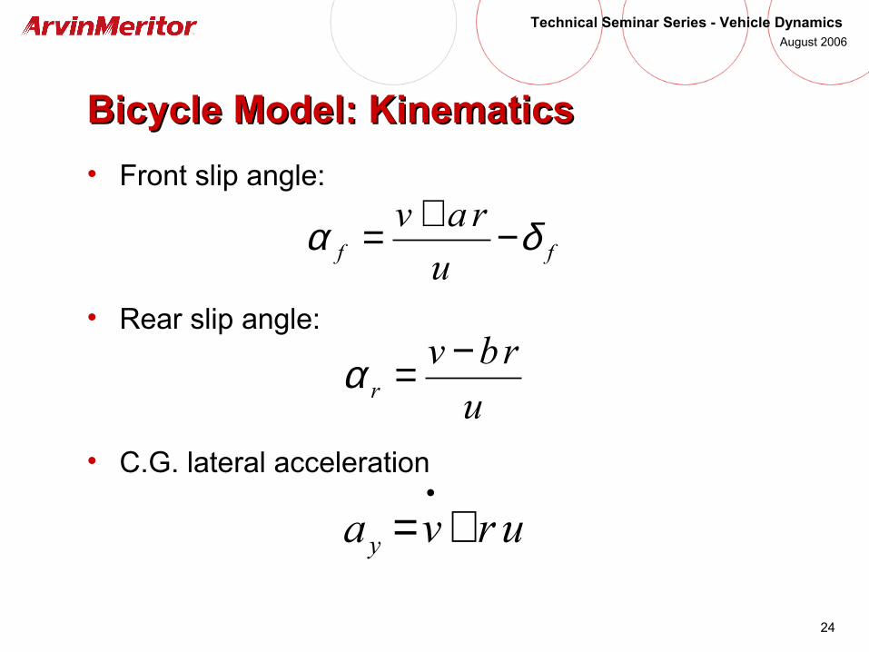
Bicycle Model: KinematicsBicycle Model: Kinematics
• Front slip angle:
• Rear slip angle:
• C.G. lateral acceleration
ff u
rav δα −+=
u
rbvr
−=α
urva y +=•
25
Technical Seminar Series - Vehicle Dynamics August 2006
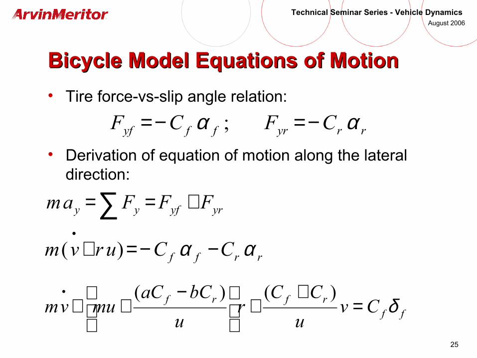
Bicycle Model Equations of MotionBicycle Model Equations of Motion
• Tire force-vs-slip angle relation:
• Derivation of equation of motion along the lateral direction:
rryrffyf CFCF αα −=−= ;
yryfyy FFFam +==∑rrff CCurvm αα −−=+
•)(
ffrfrf Cv
u
CCr
u
bCaCmuvm δ=
++
−++
• )()(
26
Technical Seminar Series - Vehicle Dynamics August 2006
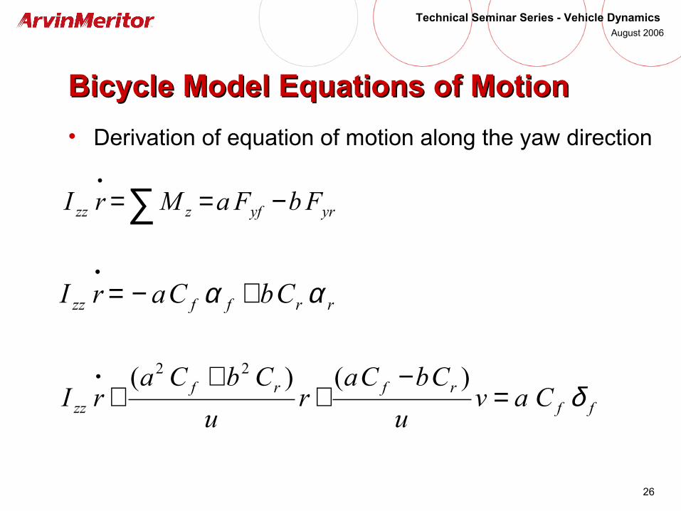
Bicycle Model Equations of MotionBicycle Model Equations of Motion
• Derivation of equation of motion along the yaw direction
yryfzzz FbFaMrI −==∑•
rrffzz CbCarI αα +−=•
ffrfrf
zz Cavu
CbCar
u
CbCarI δ=
−+
++
• )()( 22
27
Technical Seminar Series - Vehicle Dynamics August 2006
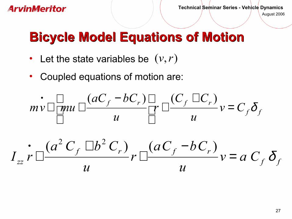
Bicycle Model Equations of MotionBicycle Model Equations of Motion
• Let the state variables be
• Coupled equations of motion are:
),( rv
ffrfrf Cv
u
CCr
u
bCaCmuvm δ=
++
−++
• )()(
ffrfrf
zz Cavu
CbCar
u
CbCarI δ=
−+
++
• )()( 22
28
Technical Seminar Series - Vehicle Dynamics August 2006
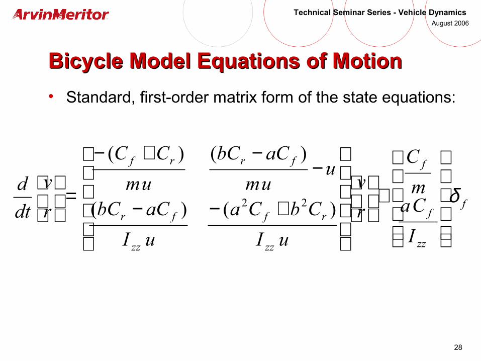
Bicycle Model Equations of MotionBicycle Model Equations of Motion
• Standard, first-order matrix form of the state equations:
f
zz
f
f
zz
rf
zz
fr
frrf
I
Cam
C
r
v
uI
CbCa
uI
aCbC
uum
aCbC
um
CC
r
v
dt
d δ
+
+−−
−−+−
=
)()(
)()(
22
29
Technical Seminar Series - Vehicle Dynamics August 2006
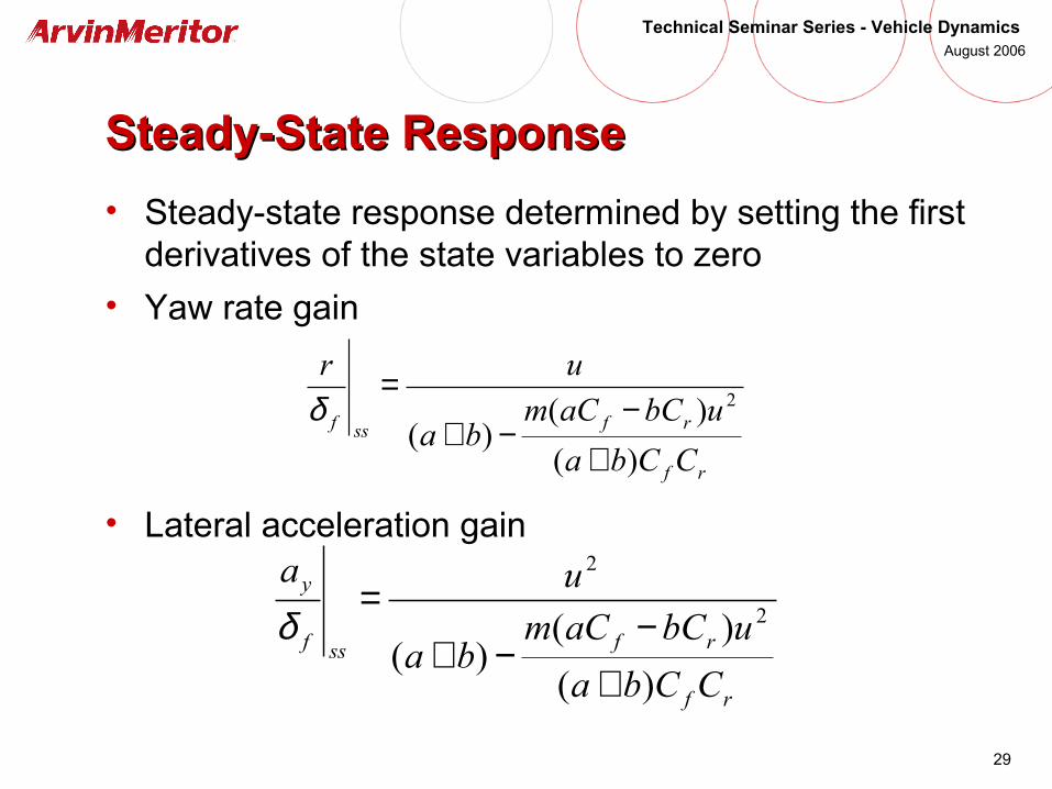
Steady-State ResponseSteady-State Response
• Steady-state response determined by setting the first derivatives of the state variables to zero
• Yaw rate gain
• Lateral acceleration gain
rf
rfssf
CCba
ubCaCmba
ur
)(
)()(
2
+−
−+=
δ
rf
rfssf
y
CCba
ubCaCmba
ua
)(
)()(
2
2
+−
−+=
δ
30
Technical Seminar Series - Vehicle Dynamics August 2006
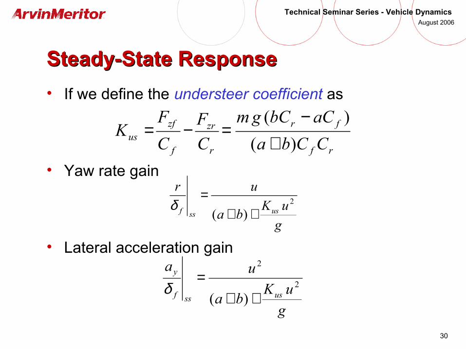
Steady-State ResponseSteady-State Response
• If we define the understeer coefficient as
• Yaw rate gain
• Lateral acceleration gain
g
uKba
ur
usssf2
)( ++=
δ
g
uKba
ua
usssf
y
2
2
)( ++=
δ
rf
fr
r
zr
f
zfus CCba
aCbCgm
C
F
C
FK
)(
)(
+−
=−=
31
Technical Seminar Series - Vehicle Dynamics August 2006
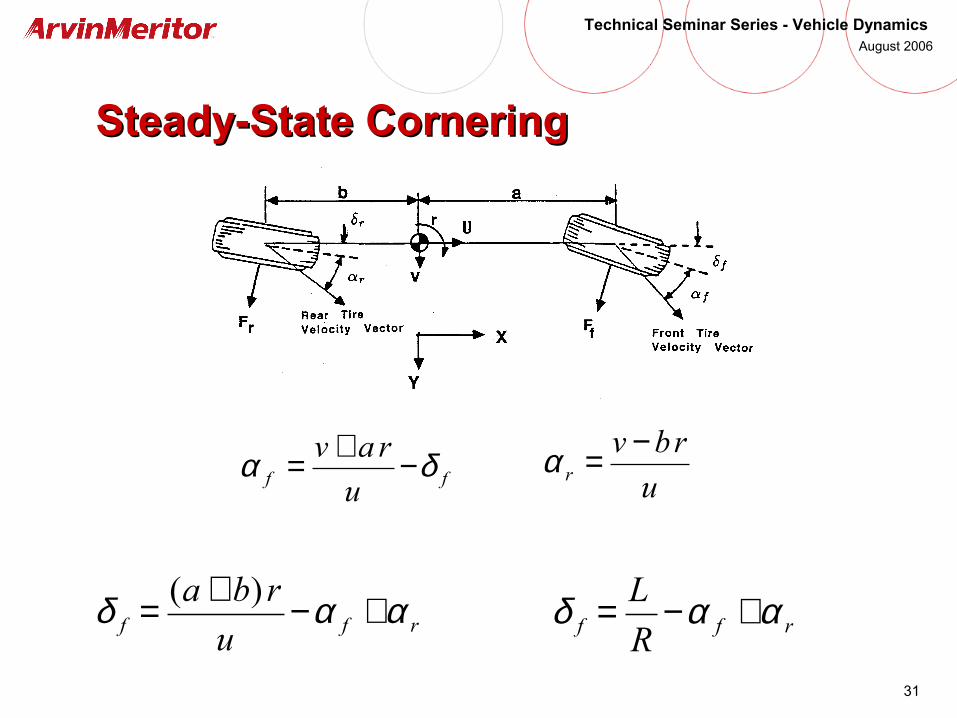
Steady-State CorneringSteady-State Cornering
rff u
rba ααδ +−+= )(rff R
L ααδ +−=
ff u
rav δα −+=u
rbvr
−=α

32
Technical Seminar Series - Vehicle Dynamics August 2006
Equilibrium Equations during Equilibrium Equations during Steady-State CorneringSteady-State Cornering
33
Technical Seminar Series - Vehicle Dynamics August 2006
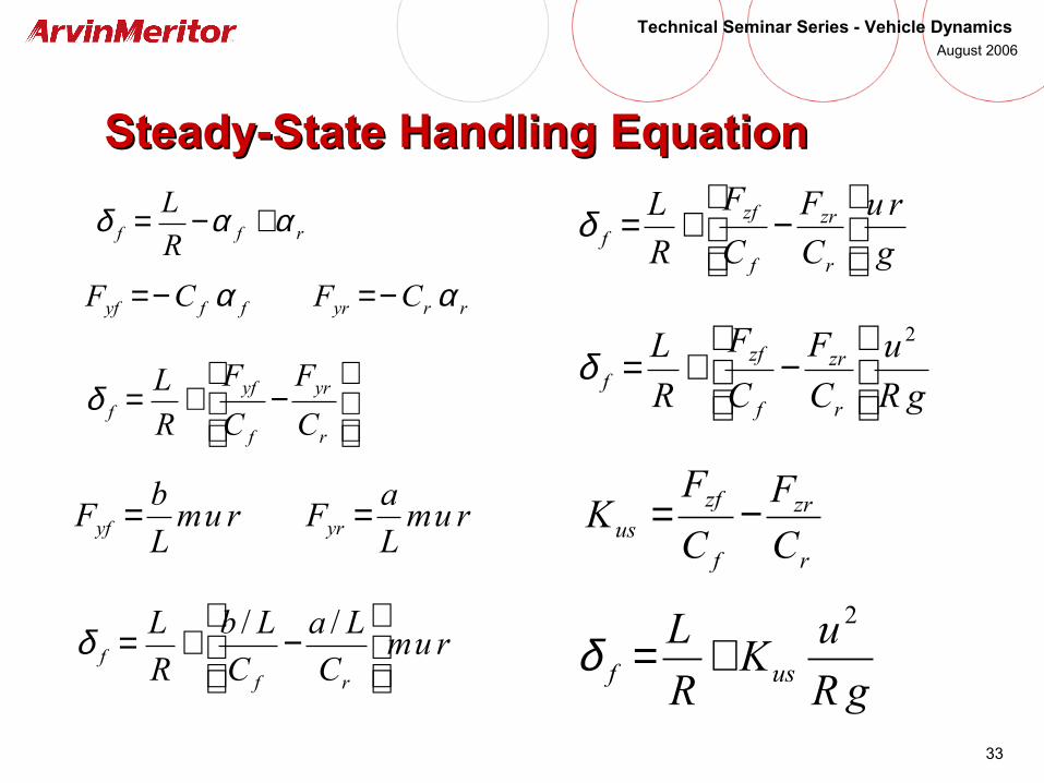
Steady-State Handling EquationSteady-State Handling Equation
rff R
L ααδ +−=
rryrffyf CFCF αα −=−=
−+=
r
yr
f
yff C
F
C
F
R
Lδ
rumL
aFrum
L
bF yryf ==
rumC
La
C
Lb
R
L
rff
−+= //δ
gR
u
C
F
C
F
R
L
r
zr
f
zff
2
−+=δ
gR
uK
R
Lusf
2
+=δ
g
ru
C
F
C
F
R
L
r
zr
f
zff
−+=δ
r
zr
f
zfus C
F
C
FK −=

34
Technical Seminar Series - Vehicle Dynamics August 2006
Characteristic Speed and Critical SpeedCharacteristic Speed and Critical Speed
• Characteristic speed (understeer vehicle) – the speed at which the steer angle required to maintain the turn radius is equal to twice the Ackermann steer angle
• Critical speed (oversteer vehicle) – the speed at which the steer angle to maintain the turn radius is equal to zero
uschar K
Lgu =
uscrit K
Lgu
−=
35
Technical Seminar Series - Vehicle Dynamics August 2006
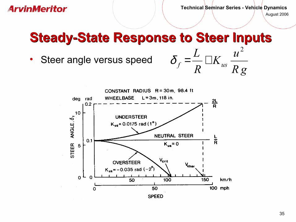
Steady-State Response to Steer InputsSteady-State Response to Steer Inputs
• Steer angle versus speedgR
uK
R
Lusf
2
+=δ

36
Technical Seminar Series - Vehicle Dynamics August 2006
Steady-State Response to Steer InputsSteady-State Response to Steer Inputs
• Curvature response
guK
L
R
usssf2
1/1
+=
δ
37
Technical Seminar Series - Vehicle Dynamics August 2006
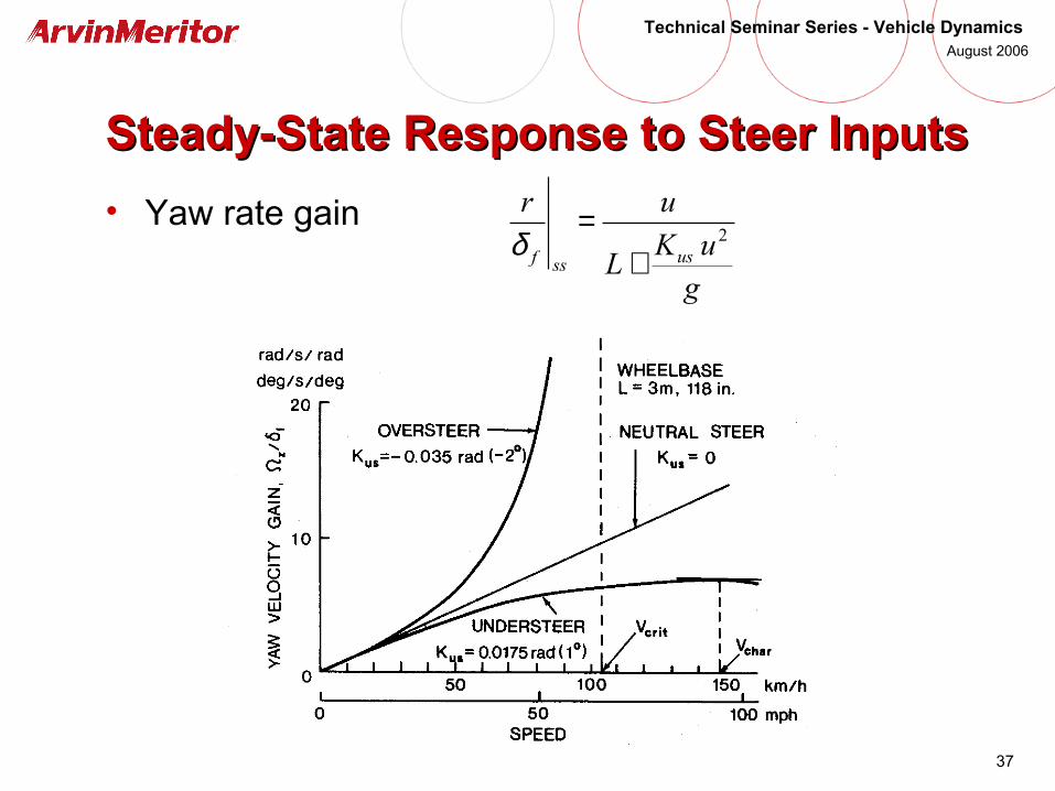
Steady-State Response to Steer InputsSteady-State Response to Steer Inputs
• Yaw rate gain
guK
L
ur
usssf2
+=
δ
38
Technical Seminar Series - Vehicle Dynamics August 2006
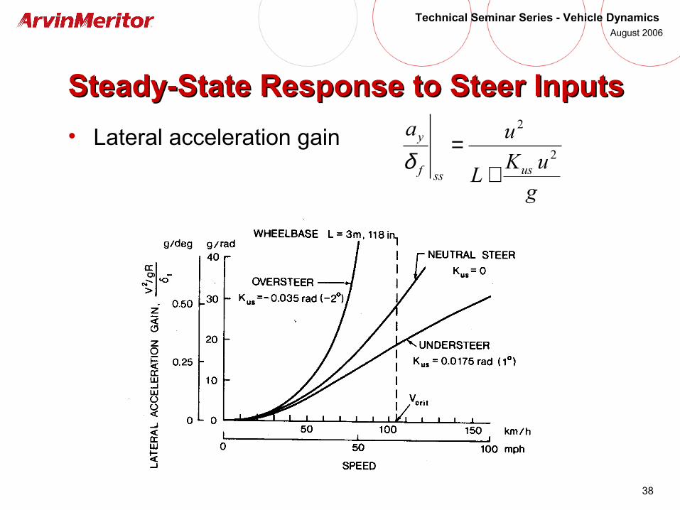
Steady-State Response to Steer InputsSteady-State Response to Steer Inputs
• Lateral acceleration gain
guK
L
ua
usssf
y
2
2
+=
δ
39
Technical Seminar Series - Vehicle Dynamics August 2006
Vehicle Tests for Handling PerformanceVehicle Tests for Handling Performance

40
Technical Seminar Series - Vehicle Dynamics August 2006
Constant Radius TestConstant Radius Test
)/( gaK
y
fus ∂
∂=
δ
g
aK
R
L yusf +=δ
41
Technical Seminar Series - Vehicle Dynamics August 2006
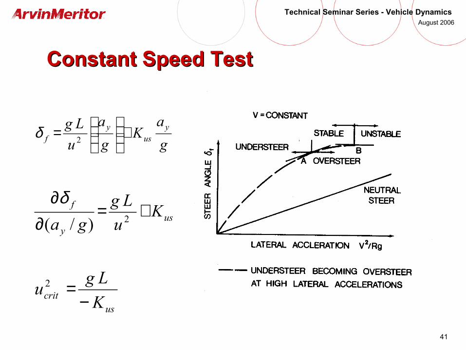
Constant Speed TestConstant Speed Test
g
aK
g
a
u
Lg yus
yf +
=
2δ
usy
f Ku
Lg
ga+=
∂∂
2)/(
δ
uscrit K
Lgu
−=2
42
Technical Seminar Series - Vehicle Dynamics August 2006
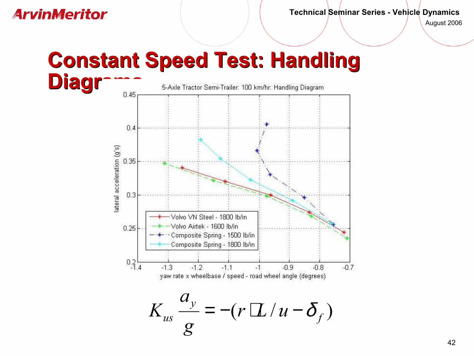
Constant Speed Test: Handling Constant Speed Test: Handling DiagramsDiagrams
)/( fy
us uLrg
aK δ−⋅−=
43
Technical Seminar Series - Vehicle Dynamics August 2006
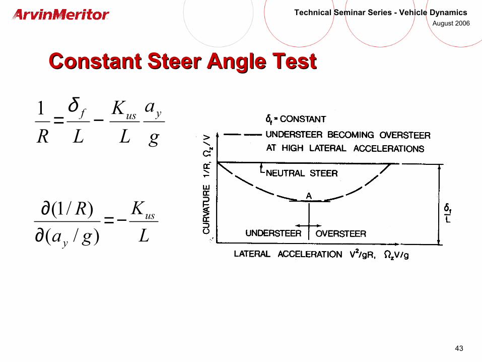
Constant Steer Angle TestConstant Steer Angle Test
g
a
L
K
LRyusf −=
δ1
L
K
ga
R us
y
−=∂∂
)/(
)/1(
44
Technical Seminar Series - Vehicle Dynamics August 2006
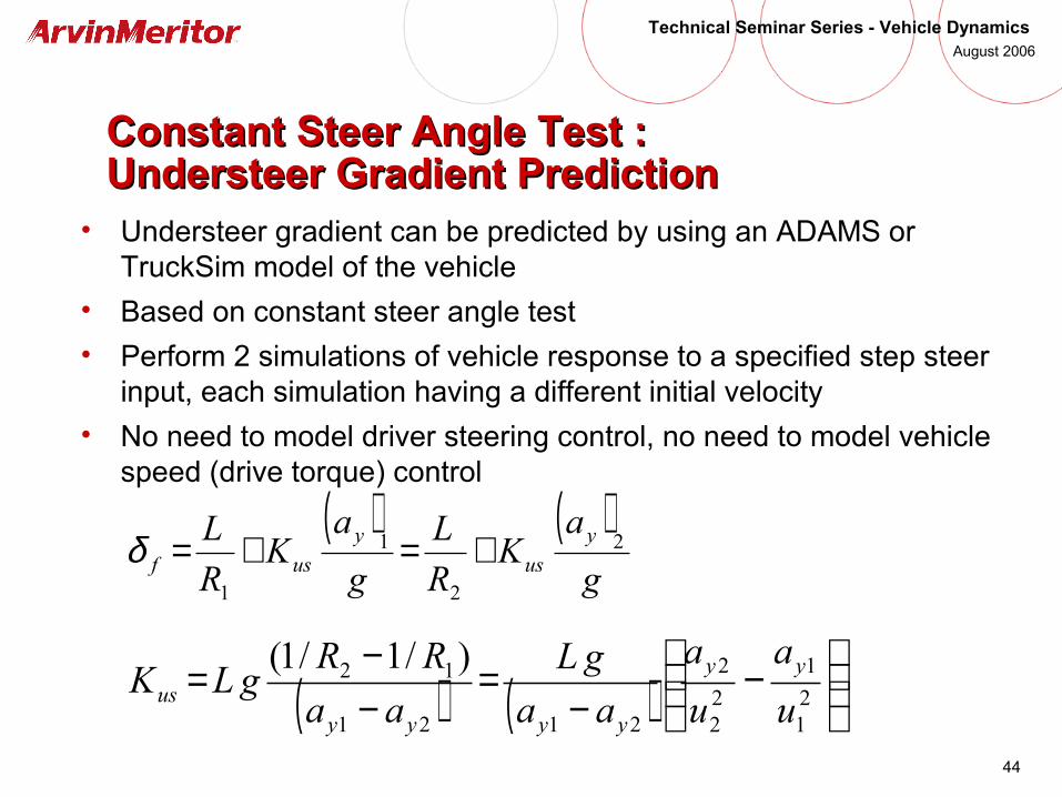
Constant Steer Angle Test : Constant Steer Angle Test : Understeer Gradient PredictionUndersteer Gradient Prediction
• Understeer gradient can be predicted by using an ADAMS or TruckSim model of the vehicle
• Based on constant steer angle test
• Perform 2 simulations of vehicle response to a specified step steer input, each simulation having a different initial velocity
• No need to model driver steering control, no need to model vehicle speed (drive torque) control
( ) ( )g
aK
R
L
g
aK
R
L y
us
y
usf2
2
1
1
+=+=δ
( ) ( )
−
−=
−−=
21
1
22
2
2121
12 )/1/1(
u
a
u
a
aa
gL
aa
RRgLK yy
yyyyus
45
Technical Seminar Series - Vehicle Dynamics August 2006
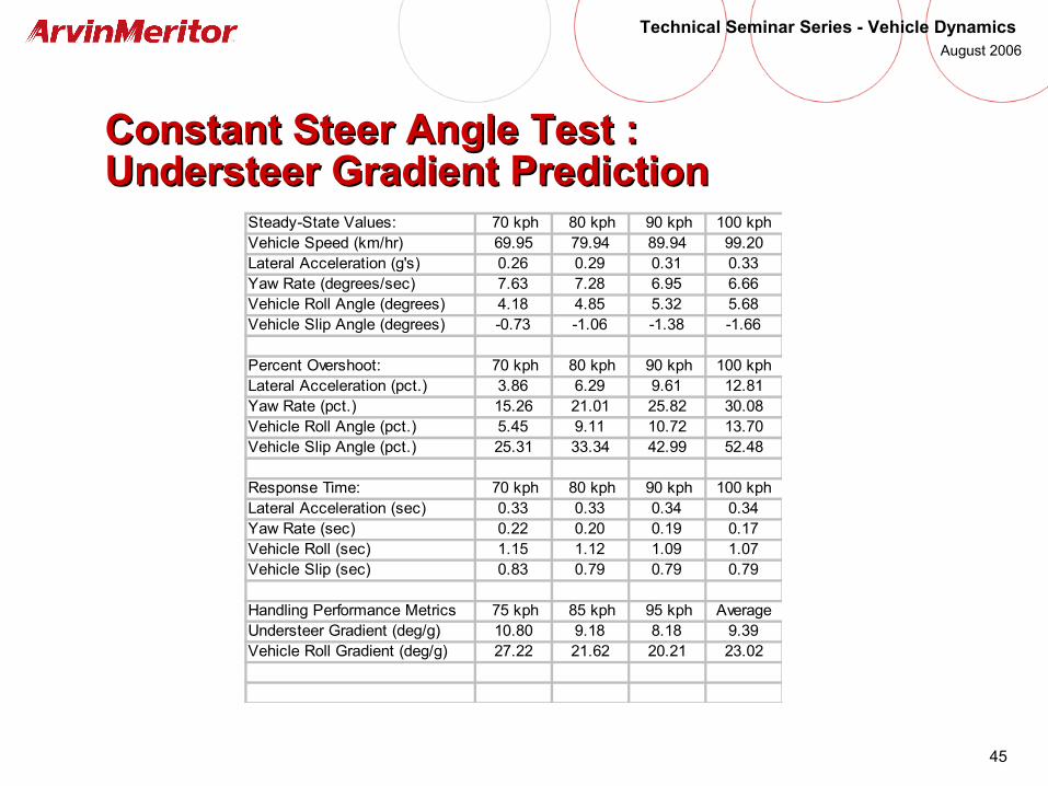
Constant Steer Angle Test : Constant Steer Angle Test : Understeer Gradient PredictionUndersteer Gradient Prediction
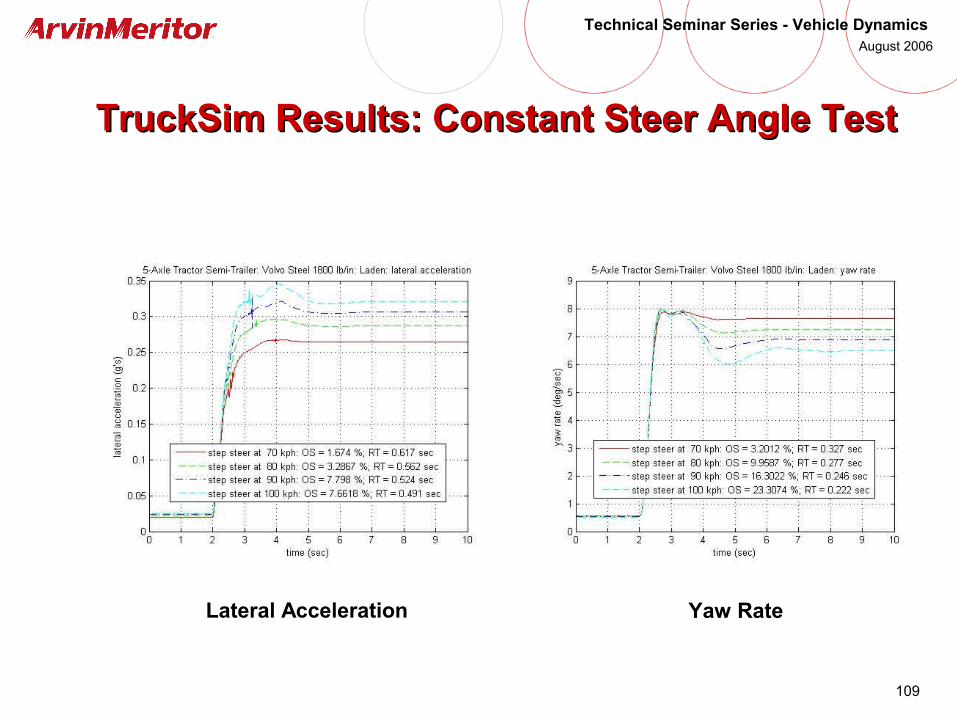
Steady-State Values: 70 kph 80 kph 90 kph 100 kph Vehicle Speed (km/hr) 69.95 79.94 89.94 99.20Lateral Acceleration (g's) 0.26 0.29 0.31 0.33Yaw Rate (degrees/sec) 7.63 7.28 6.95 6.66Vehicle Roll Angle (degrees) 4.18 4.85 5.32 5.68Vehicle Slip Angle (degrees) -0.73 -1.06 -1.38 -1.66
Percent Overshoot: 70 kph 80 kph 90 kph 100 kph Lateral Acceleration (pct.) 3.86 6.29 9.61 12.81Yaw Rate (pct.) 15.26 21.01 25.82 30.08Vehicle Roll Angle (pct.) 5.45 9.11 10.72 13.70Vehicle Slip Angle (pct.) 25.31 33.34 42.99 52.48
Response Time: 70 kph 80 kph 90 kph 100 kph Lateral Acceleration (sec) 0.33 0.33 0.34 0.34Yaw Rate (sec) 0.22 0.20 0.19 0.17Vehicle Roll (sec) 1.15 1.12 1.09 1.07Vehicle Slip (sec) 0.83 0.79 0.79 0.79
Handling Performance Metrics 75 kph 85 kph 95 kph Average Understeer Gradient (deg/g) 10.80 9.18 8.18 9.39Vehicle Roll Gradient (deg/g) 27.22 21.62 20.21 23.02

46
Technical Seminar Series - Vehicle Dynamics August 2006
Take-Away: Steady-State CorneringTake-Away: Steady-State Cornering
• Understeer gradient:
• Steady-state handling equation:
• A critical speed exists when a vehicle is oversteer• Characteristic speed is a measure of understeer• Steady-state characteristics are important performance
metrics of vehicle handling capabilities• Understeer gradient determines steady-state response• Standard tests are available for measuring understeer
gradient
r
zr
f
zfus C
F
C
FK −=
gR
uK
R
Lusf
2
+=δ
47
Technical Seminar Series - Vehicle Dynamics August 2006
Other Factors Affecting UndersteerOther Factors Affecting Understeer

48
Technical Seminar Series - Vehicle Dynamics August 2006
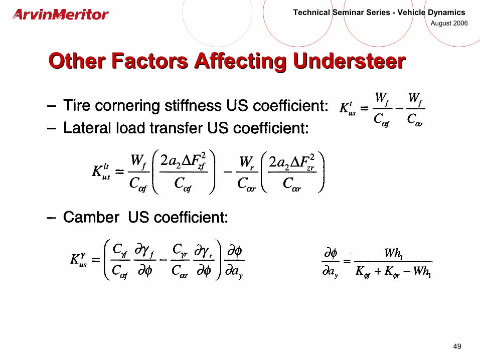
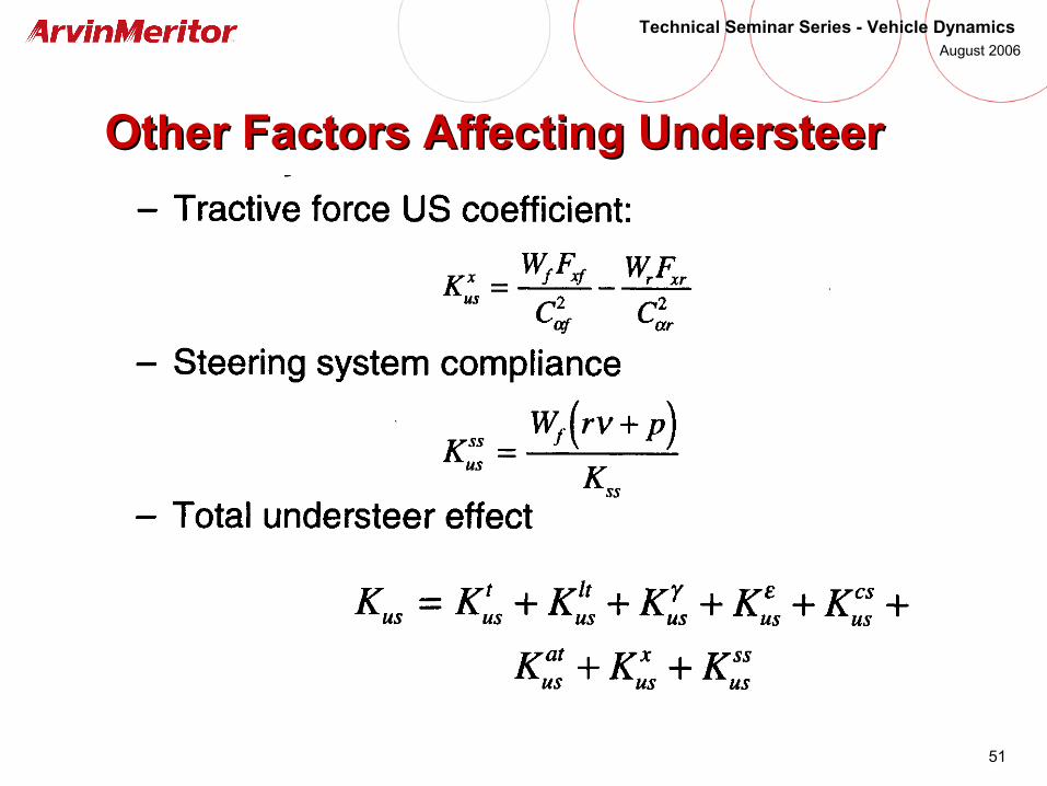
Other Factors Affecting UndersteerOther Factors Affecting Understeer
• Lateral load transfer / roll moment distribution
• Tire camber (may be induced by vehicle roll)
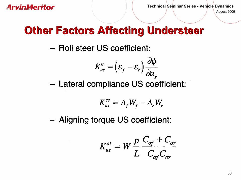
• Roll steer
• Lateral force compliance (steer and camber)
• Aligning torque compliance (steer and camber)
• Aligning torque
• Tractive force (FWD vs. RWD)
• Steering system compliance
49
Technical Seminar Series - Vehicle Dynamics August 2006
Other Factors Affecting UndersteerOther Factors Affecting Understeer
50
Technical Seminar Series - Vehicle Dynamics August 2006
Other Factors Affecting UndersteerOther Factors Affecting Understeer
51
Technical Seminar Series - Vehicle Dynamics August 2006
Other Factors Affecting UndersteerOther Factors Affecting Understeer
52
Technical Seminar Series - Vehicle Dynamics August 2006
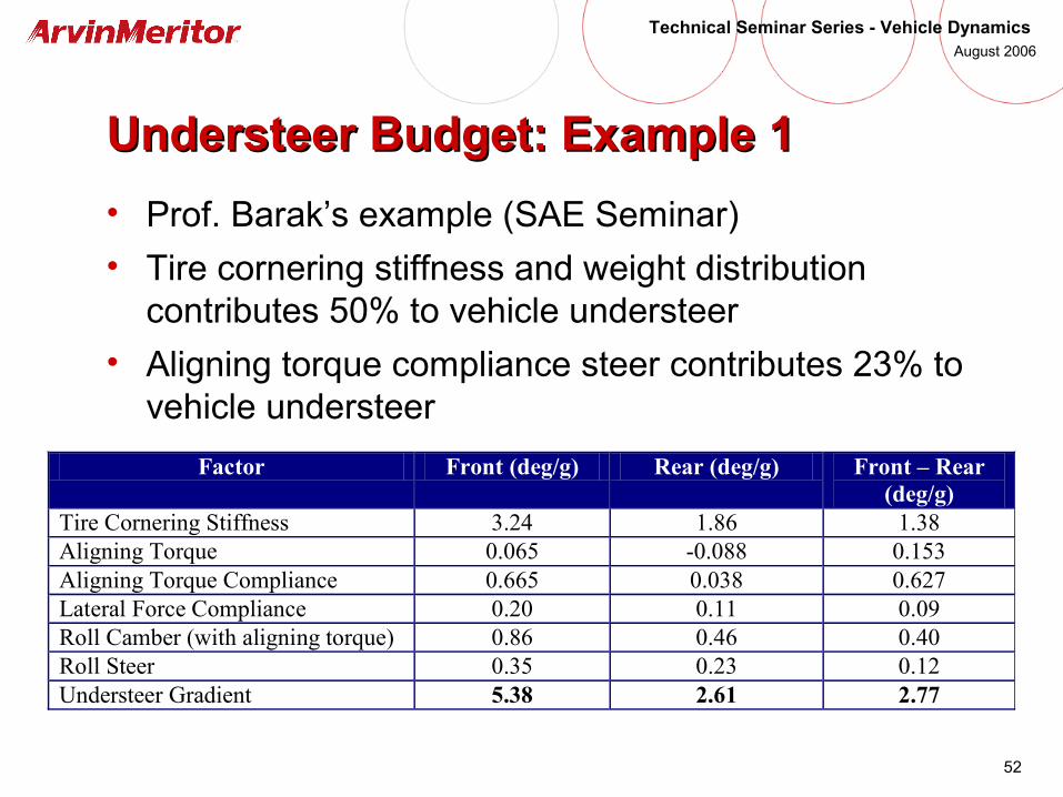
Understeer Budget: Example 1Understeer Budget: Example 1
• Prof. Barak’s example (SAE Seminar)
• Tire cornering stiffness and weight distribution contributes 50% to vehicle understeer
• Aligning torque compliance steer contributes 23% to vehicle understeer
Factor Front (deg/g) Rear (deg/g) Front – Rear (deg/g)
Tire Cornering Stiffness 3.24 1.86 1.38 Aligning Torque 0.065 -0.088 0.153 Aligning Torque Compliance 0.665 0.038 0.627 Lateral Force Compliance 0.20 0.11 0.09 Roll Camber (with aligning torque) 0.86 0.46 0.40 Roll Steer 0.35 0.23 0.12 Understeer Gradient 5.38 2.61 2.77
53
Technical Seminar Series - Vehicle Dynamics August 2006
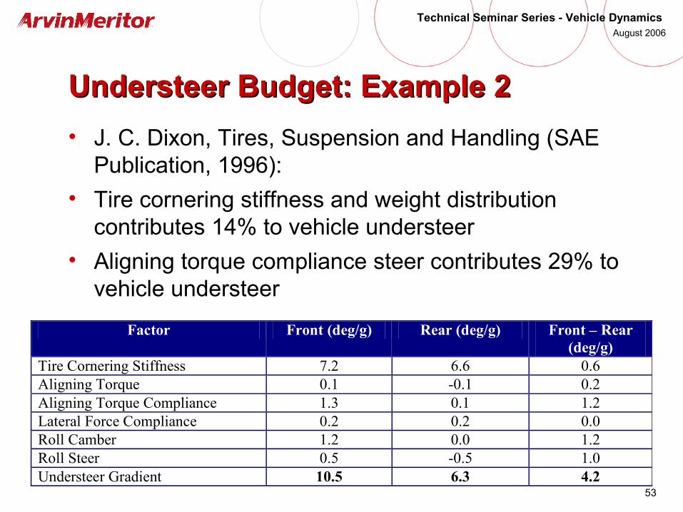
Understeer Budget: Example 2Understeer Budget: Example 2
• J. C. Dixon, Tires, Suspension and Handling (SAE Publication, 1996):
• Tire cornering stiffness and weight distribution contributes 14% to vehicle understeer
• Aligning torque compliance steer contributes 29% to vehicle understeer
Factor Front (deg/g) Rear (deg/g) Front – Rear (deg/g)
Tire Cornering Stiffness 7.2 6.6 0.6 Aligning Torque 0.1 -0.1 0.2 Aligning Torque Compliance 1.3 0.1 1.2 Lateral Force Compliance 0.2 0.2 0.0 Roll Camber 1.2 0.0 1.2 Roll Steer 0.5 -0.5 1.0 Understeer Gradient 10.5 6.3 4.2
54
Technical Seminar Series - Vehicle Dynamics August 2006
Take-Away: Factors Affecting UndersteerTake-Away: Factors Affecting Understeer
• Understeer is not determined by the ratio of axle load to tire cornering stiffness alone
• Suspension design can have a big impact on vehicle understeer/oversteer characteristics
• The steady-state handling equation derived from the linear bicycle model can still be used as long as we account for other effects that contribute to the understeer gradient

55
Technical Seminar Series - Vehicle Dynamics August 2006
Limit Handling Performance due to Limit Handling Performance due to Nonlinear Tire CharacteristicsNonlinear Tire Characteristics

56
Technical Seminar Series - Vehicle Dynamics August 2006
Limit Handling due to Tire NonlinearitiesLimit Handling due to Tire Nonlinearities
• Motivation: load sensitivity of rear axle tire lateral force• Normal force increases due to lateral load transfer
• Increase in normal force results in increase in required slip angle to maintain the same level of required lateral force
• Increase in slip angle results in decrease in cornering force
• Change in cornering compliance may result in oversteer
57
Technical Seminar Series - Vehicle Dynamics August 2006
Limit Handling due to Tire NonlinearitiesLimit Handling due to Tire Nonlinearities
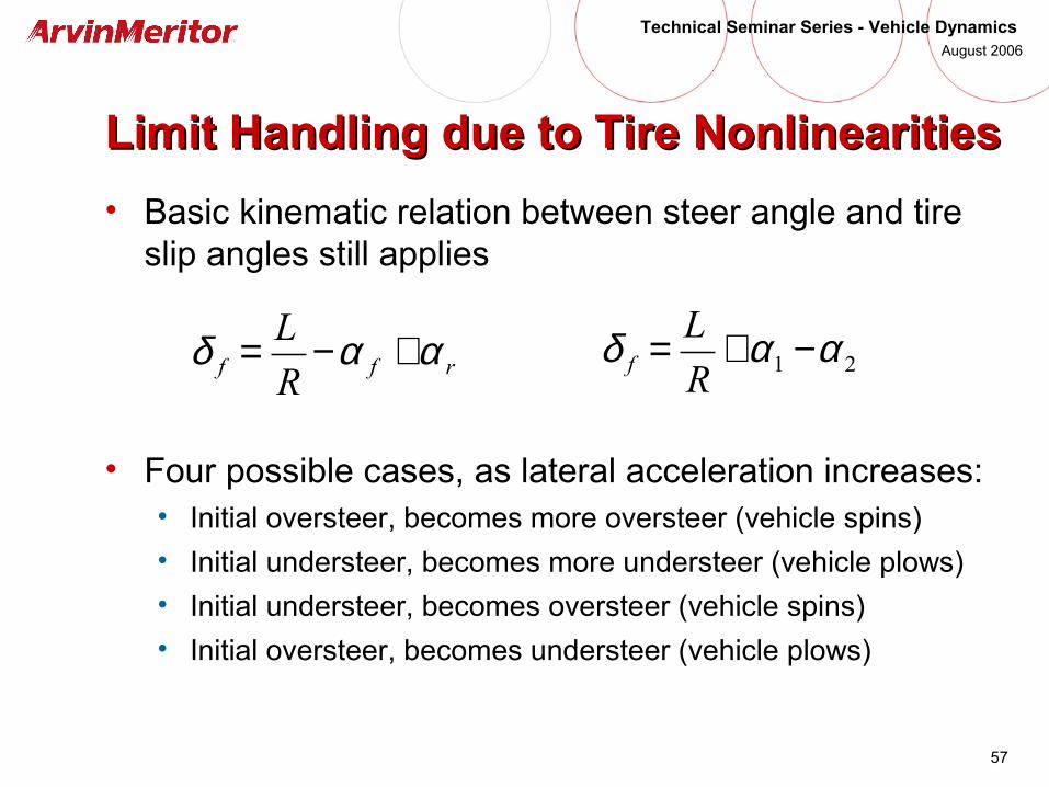
• Basic kinematic relation between steer angle and tire slip angles still applies
• Four possible cases, as lateral acceleration increases:• Initial oversteer, becomes more oversteer (vehicle spins)
• Initial understeer, becomes more understeer (vehicle plows)
• Initial understeer, becomes oversteer (vehicle spins)
• Initial oversteer, becomes understeer (vehicle plows)
rff R
L ααδ +−= 21 ααδ −+=R
Lf
58
Technical Seminar Series - Vehicle Dynamics August 2006
Limit Handling due to Tire NonlinearitiesLimit Handling due to Tire Nonlinearities
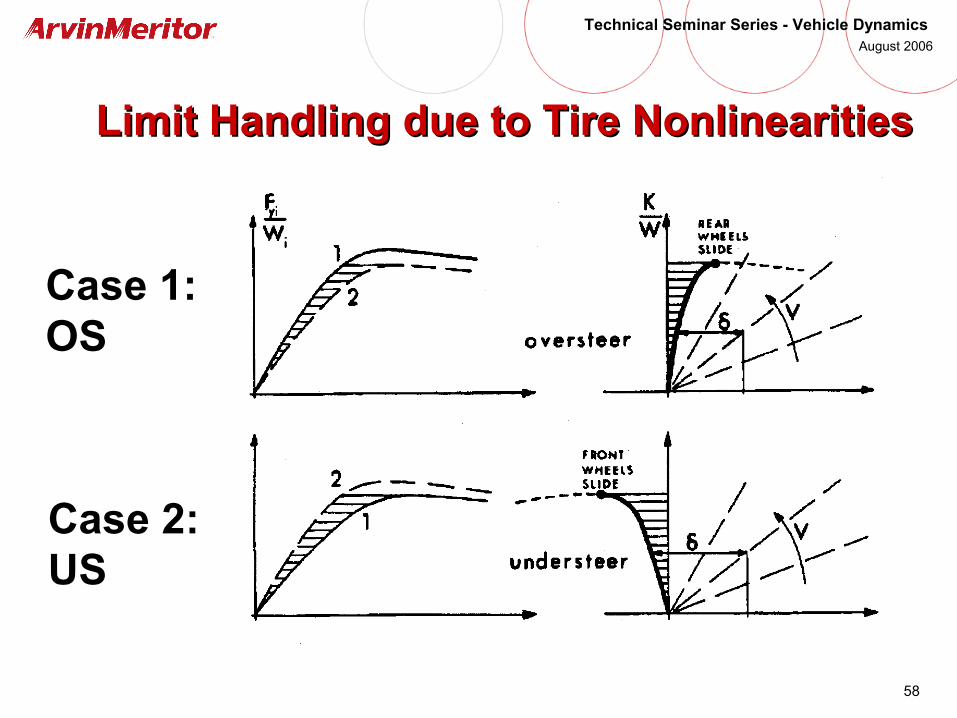
Case 1: OS
Case 2: US
59
Technical Seminar Series - Vehicle Dynamics August 2006
Limit Handling due to Tire NonlinearitiesLimit Handling due to Tire Nonlinearities
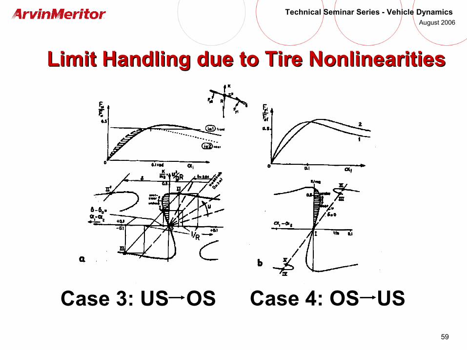
Case 3: US OS Case 4: OS US
60
Technical Seminar Series - Vehicle Dynamics August 2006
Limit Handling due to Tire NonlinearitiesLimit Handling due to Tire Nonlinearities
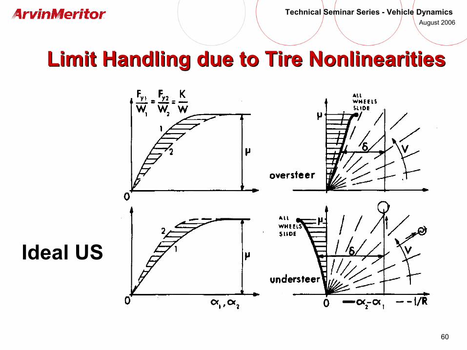
Ideal US
61
Technical Seminar Series - Vehicle Dynamics August 2006
Take-Away: Limit HandlingTake-Away: Limit Handling
• Vehicle US/OS characteristics are not constant due to nonlinearities in the tire force-deflection relations
• Other factors such as body roll will change the US/OS characteristics of the vehicle during operations
• Commercial vehicles, due to their high C.G. locations, are more susceptible to changes in US/OS
• Consider understeer gradient as the slope of (α1 – α2) vs. (Ay/g) curve
62
Technical Seminar Series - Vehicle Dynamics August 2006
Steady-State Handling of Tractor-Semi-Trailer Steady-State Handling of Tractor-Semi-Trailer CombinationsCombinations

63
Technical Seminar Series - Vehicle Dynamics August 2006
Steady-State Handling Model of Tractor-Semi-Steady-State Handling Model of Tractor-Semi-Trailer CombinationTrailer Combination
64
Technical Seminar Series - Vehicle Dynamics August 2006
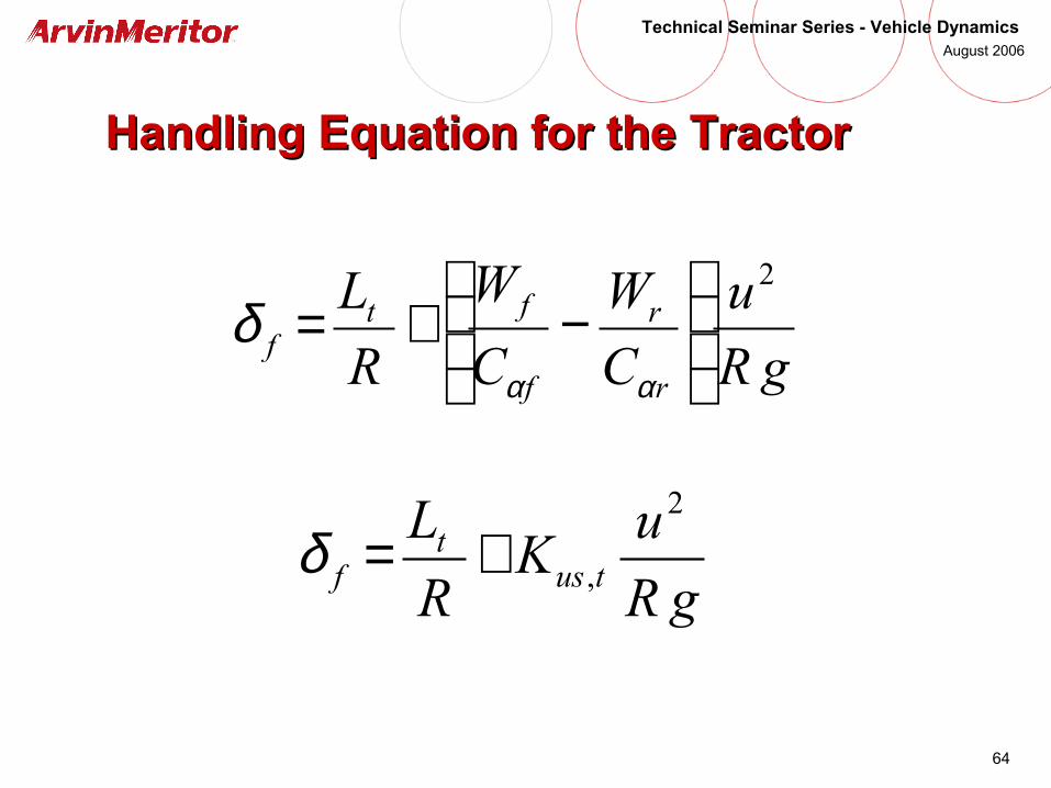
Handling Equation for the TractorHandling Equation for the Tractor
gR
uK
R
Ltus
tf
2
,+=δ
gR
u
C
W
C
W
R
L
r
r
f
ftf
2
−+=
αα
δ
65
Technical Seminar Series - Vehicle Dynamics August 2006
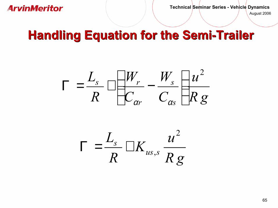
Handling Equation for the Semi-TrailerHandling Equation for the Semi-Trailer
gR
uK
R
Lsus
s2
,+=Γ
gR
u
C
W
C
W
R
L
s
s
r
rs2
−+=Γ
αα
66
Technical Seminar Series - Vehicle Dynamics August 2006
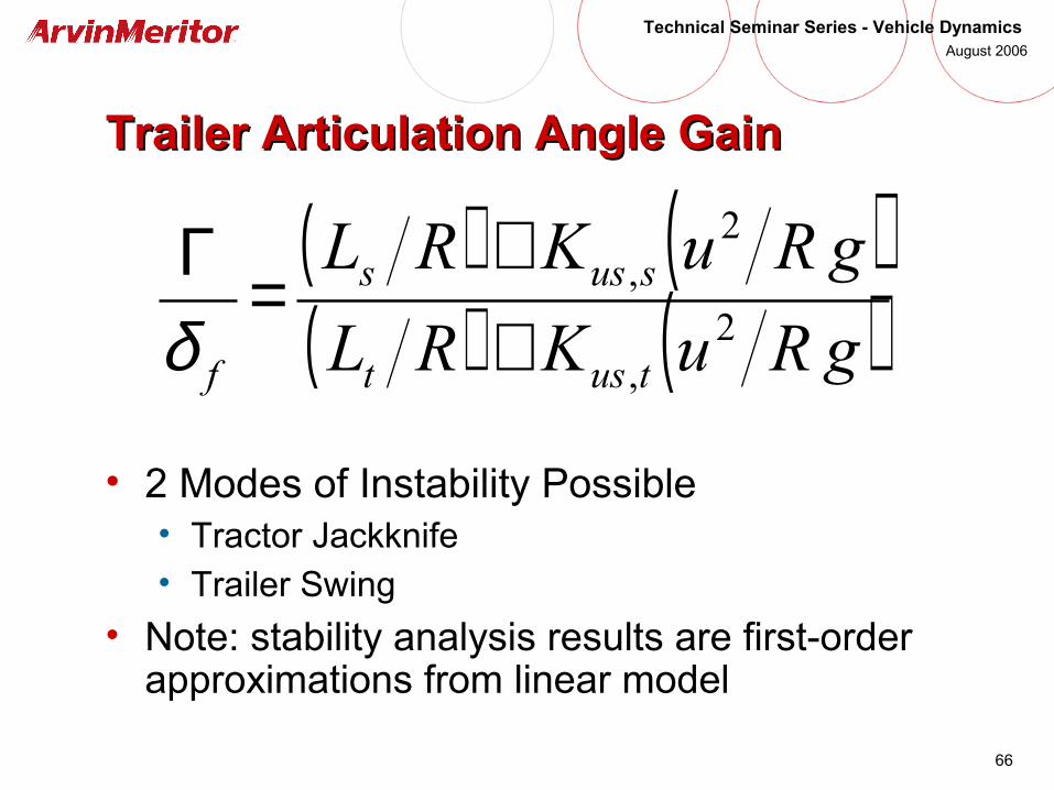
Trailer Articulation Angle GainTrailer Articulation Angle Gain
• 2 Modes of Instability Possible• Tractor Jackknife• Trailer Swing
• Note: stability analysis results are first-order approximations from linear model
( ) ( )( ) ( )gRuKRL
gRuKRL
tust
suss
f2
,
2,
++
=Γδ
67
Technical Seminar Series - Vehicle Dynamics August 2006
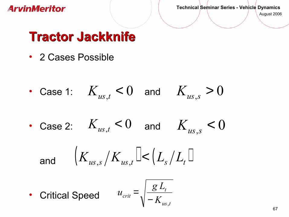
Tractor JackknifeTractor Jackknife
• 2 Cases Possible
• Case 1: and
• Case 2: and
and
• Critical Speedtus
tcrit K
Lgu
,−=
0, <tusK 0, >susK
0, <tusK 0, <susK
( ) ( )tstussus LLKK <,,
68
Technical Seminar Series - Vehicle Dynamics August 2006
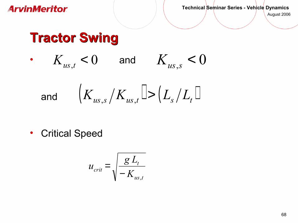
Tractor SwingTractor Swing
• and
and
• Critical Speed
tus
tcrit K
Lgu
,−=
0, <tusK 0, <susK
( ) ( )tstussus LLKK >,,
69
Technical Seminar Series - Vehicle Dynamics August 2006
Using TruckSim to Simulate Vehicle DynamicsUsing TruckSim to Simulate Vehicle Dynamics

70
Technical Seminar Series - Vehicle Dynamics August 2006
Vehicle Test or Computer Simulation?Vehicle Test or Computer Simulation?
• Vehicle tests are more appropriate when:• Test vehicle for a specific product is available
• Objective is to identify potential problems in normal operation of a specific vehicle
• A subjective evaluation is required from a driver or passenger
• Problem requires high fidelity modeling such that modeling and simulation requires too much time
• Operator safety (e.g., crash or rollover events) is not an issue
• Etc.
71
Technical Seminar Series - Vehicle Dynamics August 2006
Vehicle Test or Computer Simulation?Vehicle Test or Computer Simulation?
• Modeling and simulation are more appropriate when:• Test vehicle for a specific product is not available
• Objective is to identify the cause of performance problems
• A sensitivity study on one or more design variables is desired
• Design synthesis: evaluate candidate designs and answer many “what if” questions
• Problem of concern requires low or moderate fidelity models such that modeling and simulation can be accomplished in a reasonable amount of time
• Repeatable tests of rollover or crash events are desired
• Accident reconstruction
• Etc.

72
Technical Seminar Series - Vehicle Dynamics August 2006
TruckSimTruckSim
• Simulate dynamic behavior of trucks, buses, and tractor-semi-trailer combinations
• Simulate response of vehicle to driver inputs such as steering, braking, and acceleration
• Simulate response of vehicle to environment such as rough roads, wind
• Includes provisions for interfacing with Matlab/Simulink to simulate the response of the vehicles with active controls (e.g., active suspension or steering)
73
Technical Seminar Series - Vehicle Dynamics August 2006
Why Use TruckSim?Why Use TruckSim?
• Pre-defined vehicle models – no need to create a model from scratch; requires user to input vehicle parameters
• Fast runtime – vehicle models are represented by ordinary differential equations (ODE’s) using a minimum number of independent variables
• Easy to use interface –interfaces are intuitive, and can be navigated like a web browser
• What If Analysis – vehicle design parameters can be changed quickly, hence, design decisions regarding vehicle dynamics can be made quicker
• Mature product – developed by UMTRI in 1980’s

74
Technical Seminar Series - Vehicle Dynamics August 2006
TruckSim ModelsTruckSim Models
• Single-unit truck or bus• 1 or 2 steer axles• Single or tandem drive axles• Front: solid axle or independent suspension• Rear: solid axle suspension• Frame twist feature available with custom license
• Tractor-semi-trailer combination• Tractor: 2 or 3 axles, all solid axle suspensions• Semi-trailer: 1, 2, or 3 axles, all solid axle suspensions
• A-train doubles• Double trailers with single trailer axles
• Special configurations possible with custom license
75
Technical Seminar Series - Vehicle Dynamics August 2006
TruckSim: Typical ScenariosTruckSim: Typical Scenarios
• Constant Radius Test
• Step Steer Test
• Double Lane Change
• Straight-line braking (constant-µ or split-µ)
• Braking while turning
• Acceleration
• Rollover: fish-hook maneuver
76
Technical Seminar Series - Vehicle Dynamics August 2006
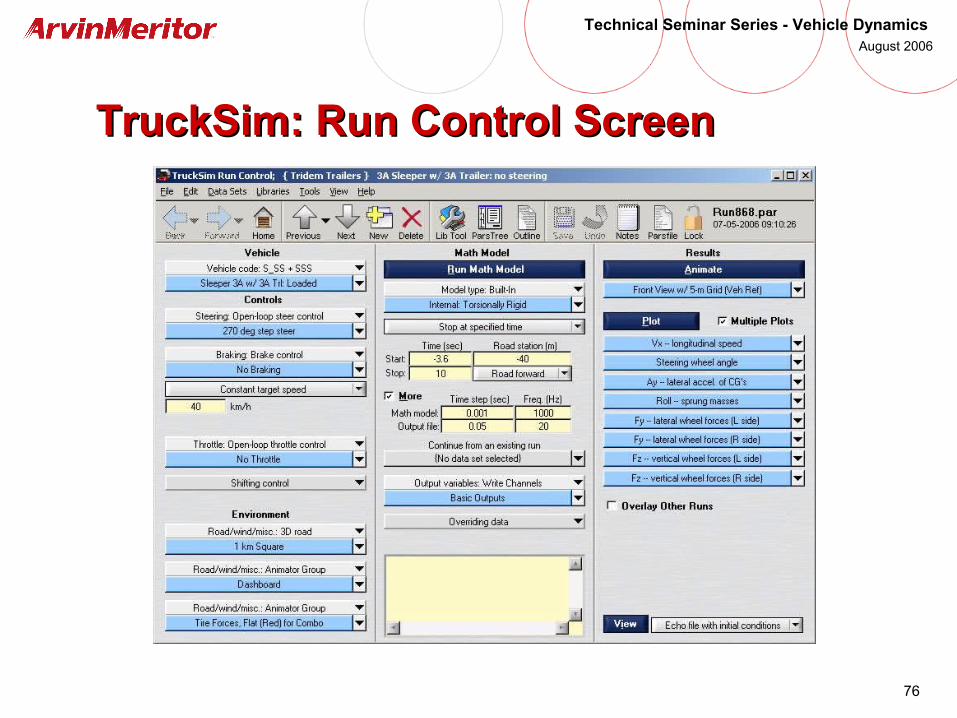
TruckSim: Run Control ScreenTruckSim: Run Control Screen
77
Technical Seminar Series - Vehicle Dynamics August 2006
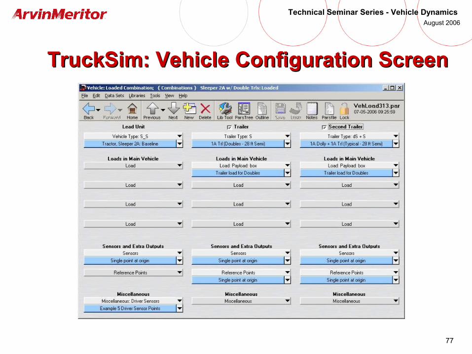
TruckSim: Vehicle Configuration ScreenTruckSim: Vehicle Configuration Screen
78
Technical Seminar Series - Vehicle Dynamics August 2006
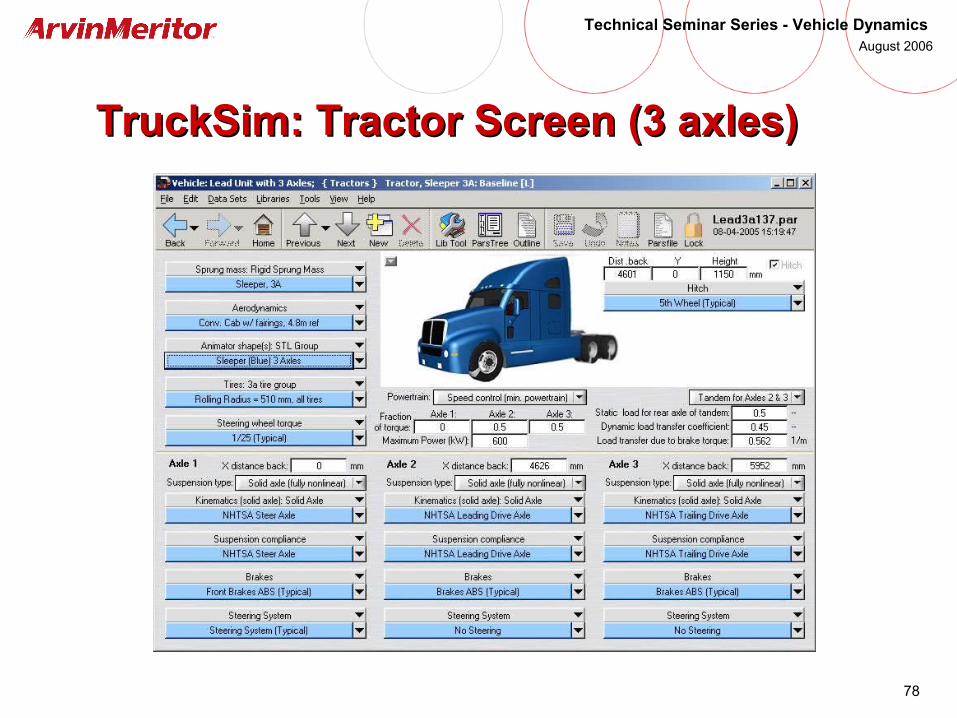
TruckSim: Tractor Screen (3 axles)TruckSim: Tractor Screen (3 axles)

79
Technical Seminar Series - Vehicle Dynamics August 2006
TruckSim: Trailer Screen (3 axles)TruckSim: Trailer Screen (3 axles)

80
Technical Seminar Series - Vehicle Dynamics August 2006
TruckSim: Trailer Payload ScreenTruckSim: Trailer Payload Screen
81
Technical Seminar Series - Vehicle Dynamics August 2006
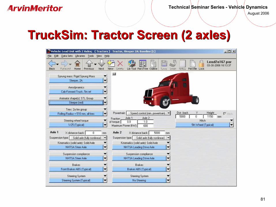
TruckSim: Tractor Screen (2 axles)TruckSim: Tractor Screen (2 axles)

82
Technical Seminar Series - Vehicle Dynamics August 2006
TruckSim: Tractor Sprung Mass ScreenTruckSim: Tractor Sprung Mass Screen
83
Technical Seminar Series - Vehicle Dynamics August 2006
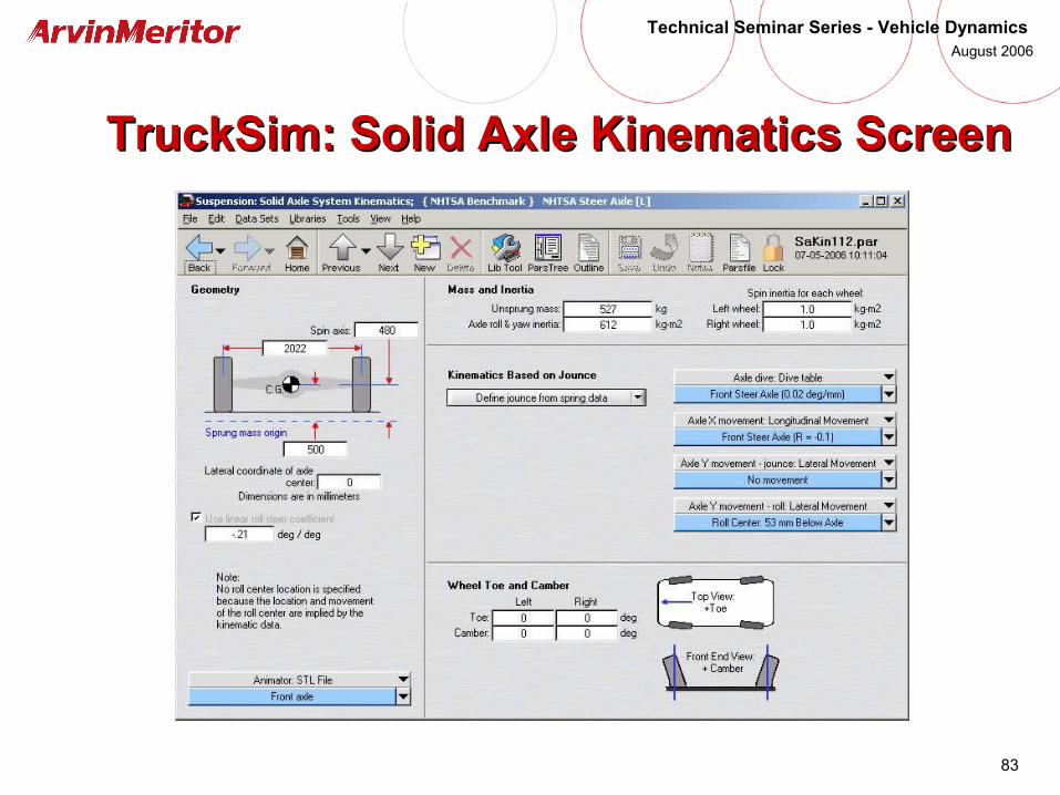
TruckSim: Solid Axle Kinematics ScreenTruckSim: Solid Axle Kinematics Screen

84
Technical Seminar Series - Vehicle Dynamics August 2006
TruckSim: Axle Lateral .vs. Roll MotionTruckSim: Axle Lateral .vs. Roll Motion

85
Technical Seminar Series - Vehicle Dynamics August 2006
TruckSim: Suspension ScreenTruckSim: Suspension Screen

86
Technical Seminar Series - Vehicle Dynamics August 2006
TruckSim: Suspension ComplianceTruckSim: Suspension Compliance

87
Technical Seminar Series - Vehicle Dynamics August 2006
TruckSim: Suspension DampingTruckSim: Suspension Damping

88
Technical Seminar Series - Vehicle Dynamics August 2006
TruckSim: Auxiliary Roll StiffnessTruckSim: Auxiliary Roll Stiffness
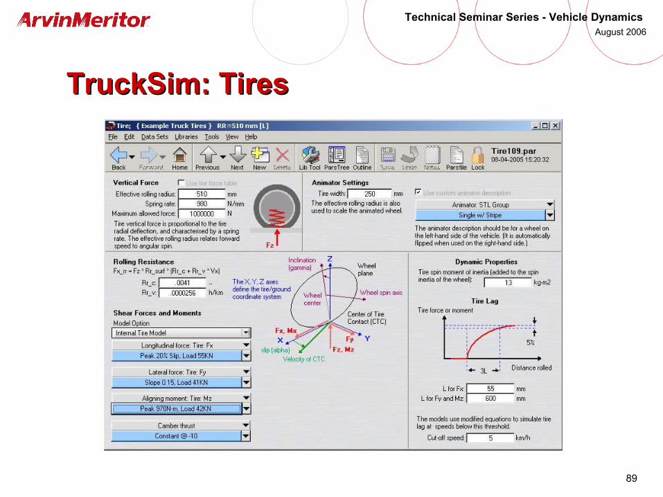
89
Technical Seminar Series - Vehicle Dynamics August 2006
TruckSim: TiresTruckSim: Tires

90
Technical Seminar Series - Vehicle Dynamics August 2006
TruckSim: Tire Data - Longitudinal ForcesTruckSim: Tire Data - Longitudinal Forces
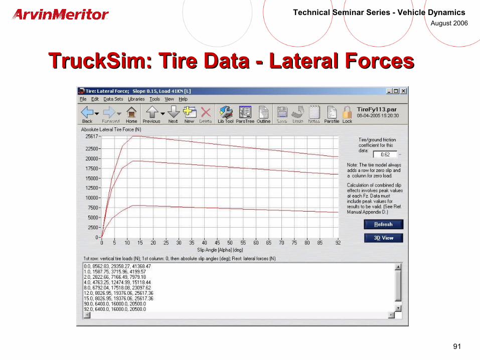
91
Technical Seminar Series - Vehicle Dynamics August 2006
TruckSim: Tire Data - Lateral ForcesTruckSim: Tire Data - Lateral Forces
92
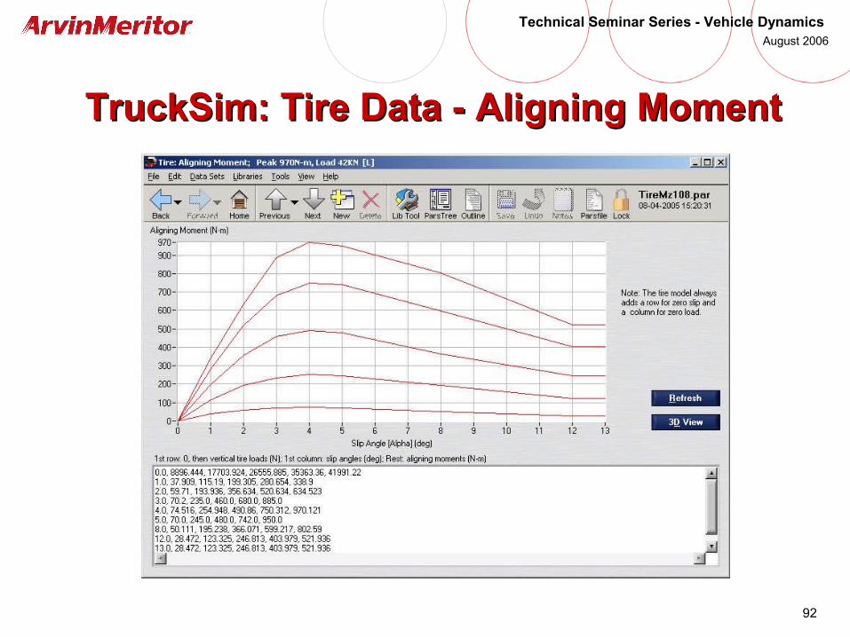
Technical Seminar Series - Vehicle Dynamics August 2006
TruckSim: Tire Data - Aligning MomentTruckSim: Tire Data - Aligning Moment
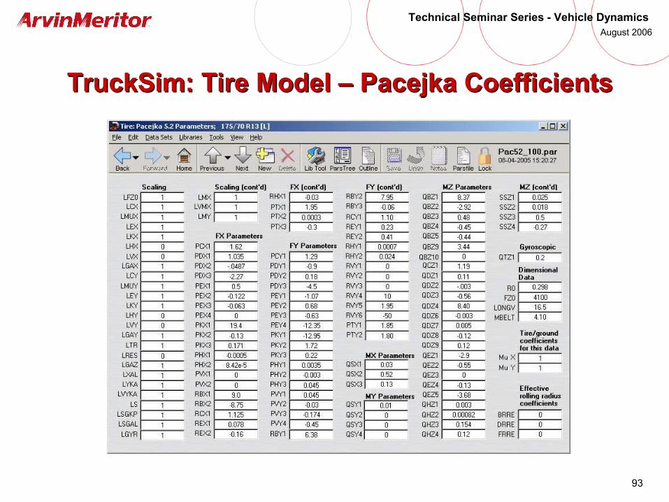
93
Technical Seminar Series - Vehicle Dynamics August 2006
TruckSim: Tire Model – Pacejka CoefficientsTruckSim: Tire Model – Pacejka Coefficients
94
Technical Seminar Series - Vehicle Dynamics August 2006
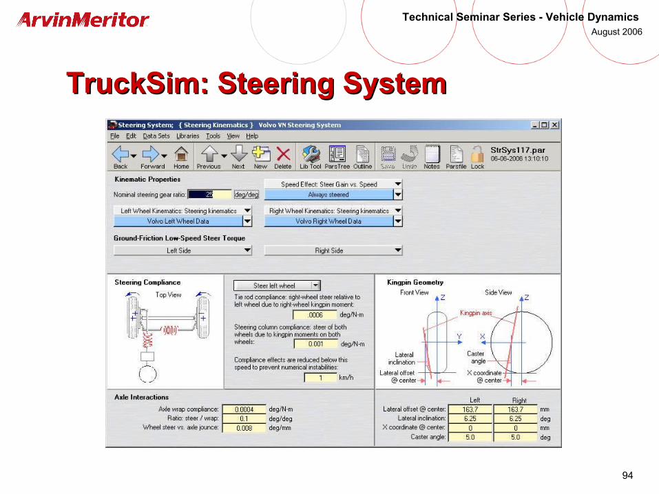
TruckSim: Steering SystemTruckSim: Steering System
95
Technical Seminar Series - Vehicle Dynamics August 2006
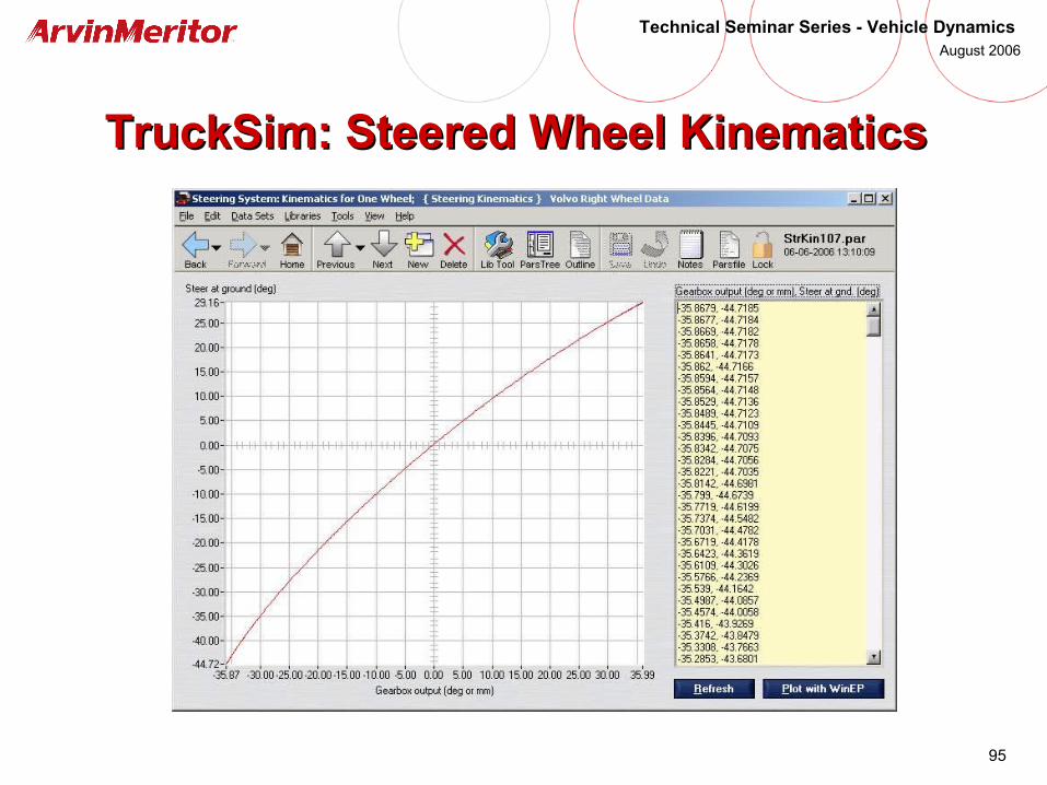
TruckSim: Steered Wheel KinematicsTruckSim: Steered Wheel Kinematics
96
Technical Seminar Series - Vehicle Dynamics August 2006
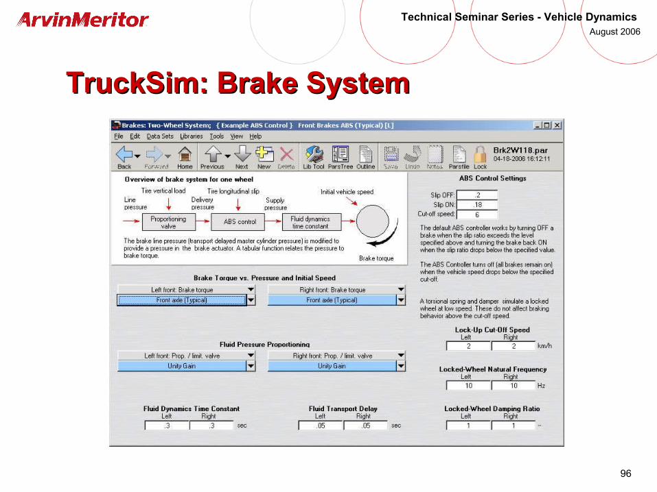
TruckSim: Brake SystemTruckSim: Brake System
97
Technical Seminar Series - Vehicle Dynamics August 2006
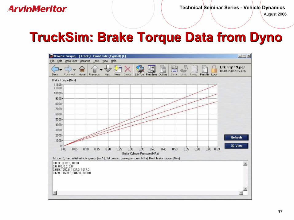
TruckSim: Brake Torque Data from DynoTruckSim: Brake Torque Data from Dyno
98
Technical Seminar Series - Vehicle Dynamics August 2006
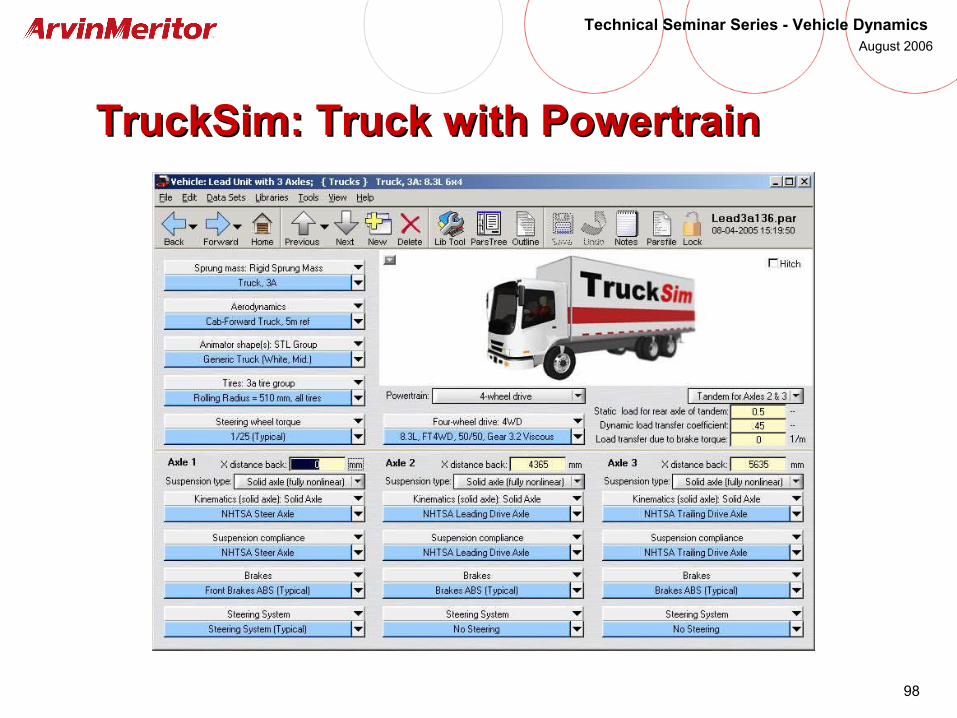
TruckSim: Truck with PowertrainTruckSim: Truck with Powertrain
99
Technical Seminar Series - Vehicle Dynamics August 2006
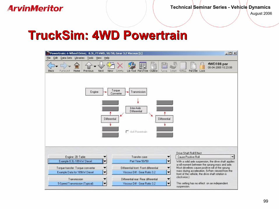
TruckSim: 4WD PowertrainTruckSim: 4WD Powertrain
100
Technical Seminar Series - Vehicle Dynamics August 2006
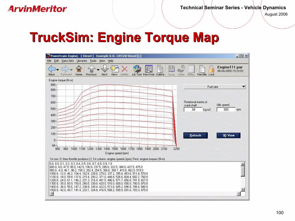
TruckSim: Engine Torque MapTruckSim: Engine Torque Map

101
Technical Seminar Series - Vehicle Dynamics August 2006
TruckSim: Transmission Gear RatiosTruckSim: Transmission Gear Ratios
102
Technical Seminar Series - Vehicle Dynamics August 2006
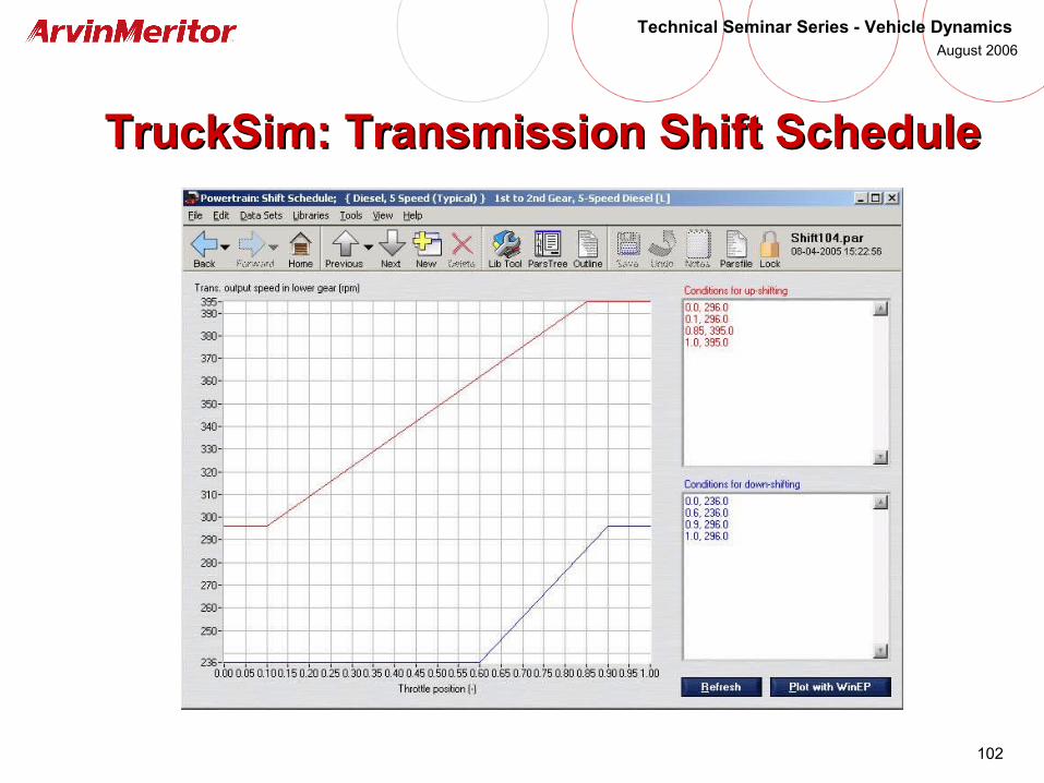
TruckSim: Transmission Shift ScheduleTruckSim: Transmission Shift Schedule

103
Technical Seminar Series - Vehicle Dynamics August 2006
TruckSim: Viscous DifferentialTruckSim: Viscous Differential
104
Technical Seminar Series - Vehicle Dynamics August 2006
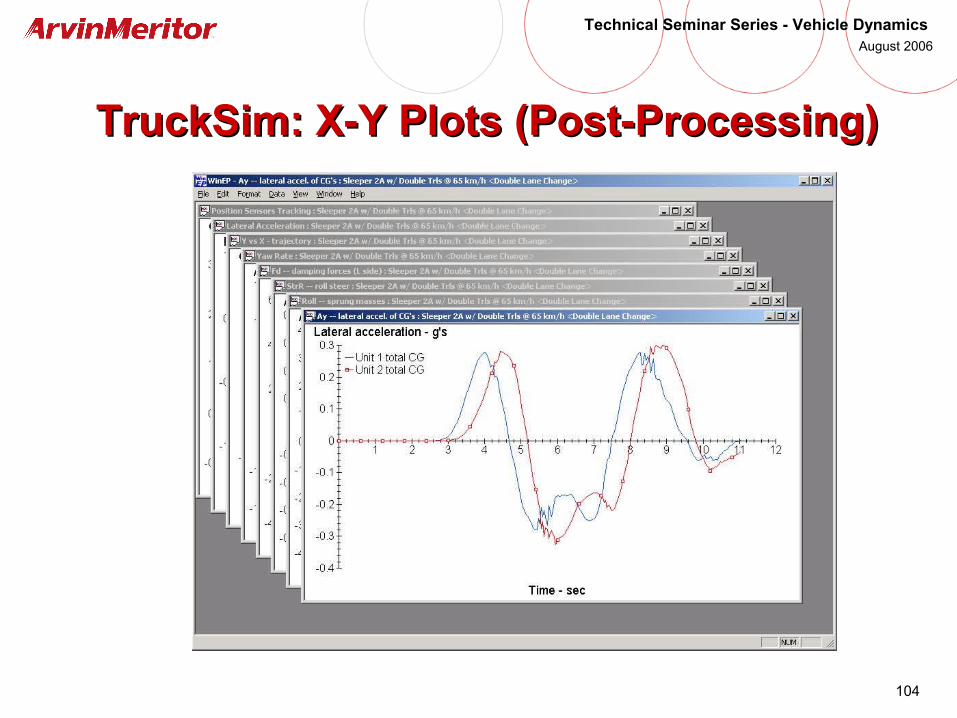
TruckSim: X-Y Plots (Post-Processing) TruckSim: X-Y Plots (Post-Processing)

105
Technical Seminar Series - Vehicle Dynamics August 2006
Embedding a TruckSim Model in Embedding a TruckSim Model in Matlab/SimulinkMatlab/Simulink
106
Technical Seminar Series - Vehicle Dynamics August 2006
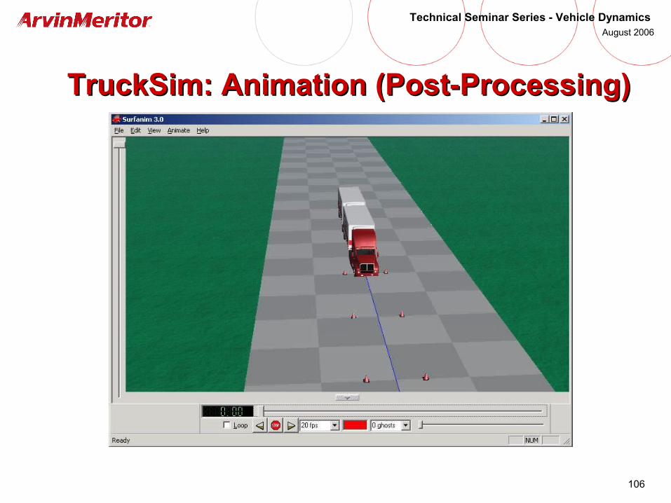
TruckSim: Animation (Post-Processing)TruckSim: Animation (Post-Processing)
107
Technical Seminar Series - Vehicle Dynamics August 2006
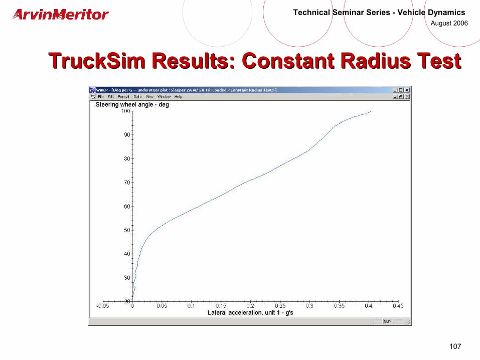
TruckSim Results: Constant Radius TestTruckSim Results: Constant Radius Test
108
Technical Seminar Series - Vehicle Dynamics August 2006
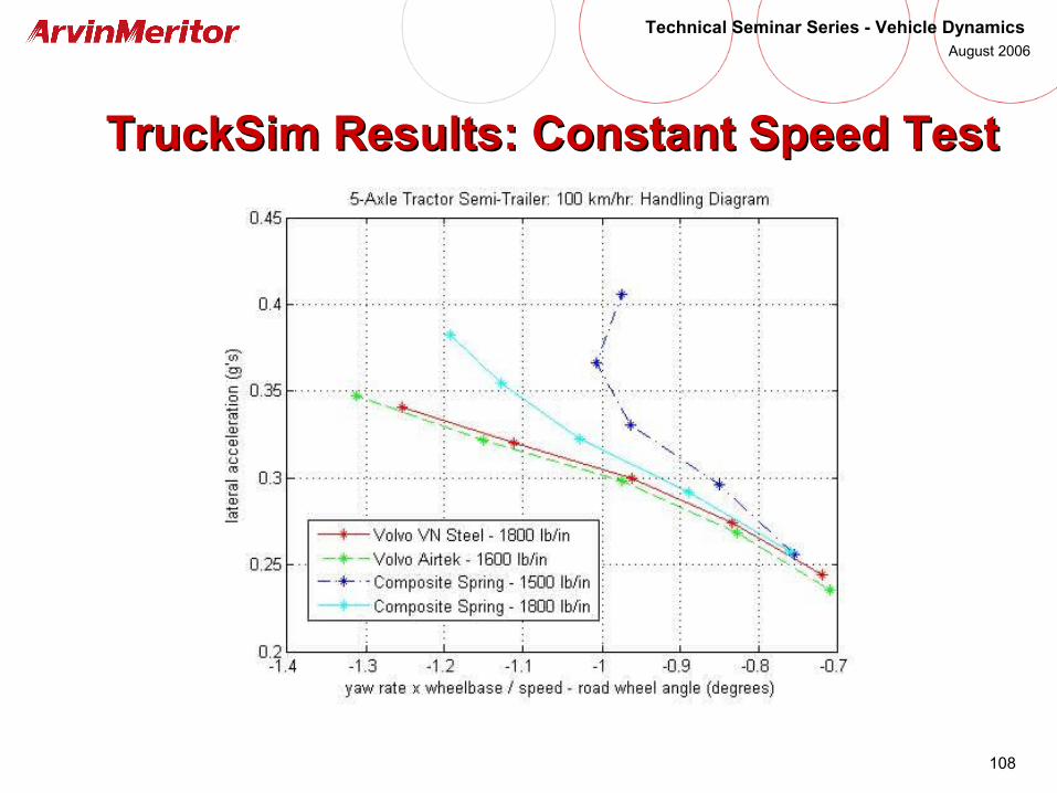
TruckSim Results: Constant Speed TestTruckSim Results: Constant Speed Test
109
Technical Seminar Series - Vehicle Dynamics August 2006
TruckSim Results: Constant Steer Angle TestTruckSim Results: Constant Steer Angle Test
Lateral Acceleration Yaw Rate
110
Technical Seminar Series - Vehicle Dynamics August 2006
Summary of Suspension Characterization Summary of Suspension Characterization Inputs Required in TruckSimInputs Required in TruckSim
• Suspension kinematics• Axle steer vs. axle roll• Axle dive vs. wheel travel• Wheel recession vs. jounce• Lateral motion vs. jounce• Lateral motion vs. axle roll• Toe and camber settings• Axle steer vs. axle wrap• Axle steer vs. wheel travel• Left wheel vs. right wheel
steer angle (Ackerman)• Spring and shock motion
ratios
• Suspension compliance• Spring force vs. displacement• Shock force vs. velocity• Auxiliary roll stiffness• Axle lateral stiffness• Axle fore-aft stiffness• Toe angle vs. Fx• Steer angle vs. Fy• Steer angle vs. Mz• Camber angle vs. Fx• Camber angle vs. Fy• Camber angle vs. Mz
111
Technical Seminar Series - Vehicle Dynamics August 2006
Questions?Questions?