vapor intrusion guidance: site assessment, mitigation
TRANSCRIPT
Charles D. Baker Governor Karyn E. Polito Lieutenant Governor
Matthew A. Beaton Secretary
Martin Suuberg Commissioner
VAPOR INTRUSION GUIDANCE:
SITE ASSESSMENT, MITIGATION AND CLOSURE
Policy #WSC-16-435
This document provides guidance on investigating, assessing, understanding, and mitigating vapor intrusion at disposal sites regulated under Massachusetts General Law chapter 21E and the Massachusetts Contingency Plan (the “MCP” or 310 CMR 40.0000). This document is intended solely as guidance. It does not create any substantive or procedural rights, and is not enforceable by any party in any administrative proceeding with the Commonwealth. This document provides guidance on approaches MassDEP considers acceptable for meeting the general requirements set forth in the MCP. Parties using this guidance should be aware that other acceptable alternatives may be available for achieving compliance with general regulatory requirements.
_____________________________
Paul W. Locke Assistant Commissioner Bureau of Waste Site Cleanup October 14, 2016

MassDEP VAPOR INTRUSION GUIDANCE: SITE ASSESSMENT, MITIGATION AND CLOSURE OCTOBER 2016
i
Contents
DISCLAIMER .................................................................................................................. V
1. INTRODUCTION ............................................................................................... 1
1.1 PURPOSE ..................................................................................................................... 1 1.2 GUIDANCE OVERVIEW ................................................................................................... 2 1.3 WHEN TO EVALUATE THE VAPOR INTRUSION PATHWAY ................................................... 3 1.3.1 VOCs in Indoor Air .............................................................................................. 5 1.3.2 VOCs in Soil ....................................................................................................... 5 1.3.3 VOCs in Groundwater ......................................................................................... 6 1.3.4 Other Factors ...................................................................................................... 7
2. ASSESSMENT ................................................................................................ 10
2.1 CONCEPTUAL SITE MODEL ............................................................................................11 2.1.1 Identification of Sources of OHM ........................................................................13 2.2 VAPOR INTRUSION PATHWAY ASSESSMENT ...................................................................13 2.2.1 Groundwater ......................................................................................................14 2.2.2 Soil, Exterior Soil Gas and Sub-Slab Soil Gas ...................................................17 2.2.3 Special Considerations for the Assessment of Petroleum Vapor Intrusion from
Discrete, Well-defined and Stable Petroleum Sources of OHM ..........................21 2.2.4 Indoor Air ...........................................................................................................24 2.2.5 Outdoor Air ........................................................................................................29 2.2.6 Non-Aqueous Phase Liquids ..............................................................................31 2.2.7 Preferential Pathways ........................................................................................31 2.2.8 Lines of Evidence Interpretation for the Presence of a Current Vapor Intrusion
Pathway .............................................................................................................32 2.3 INDOOR AIR EXPOSURE ASSESSMENT ...........................................................................35 2.3.1 Contaminants of Concern ..................................................................................35 2.3.2 Site Receptors, Activities, and Uses...................................................................36 2.3.3 Exposure Point Concentrations ..........................................................................37 2.3.4 Exposure Assumptions ......................................................................................41 2.4 RISK CHARACTERIZATION .............................................................................................42 2.4.1 General Risk Characterization Requirements ....................................................42 2.4.2 Method 1 Risk Characterizations .......................................................................43 2.4.3 Method 2 Risk Characterizations .......................................................................43 2.4.4 Method 3 Risk Characterizations .......................................................................43
3. MITIGATION OF THE VAPOR INTRUSION PATHWAY ................................ 45
3.1 ADDRESSING SOURCES OF OIL AND/OR HAZARDOUS MATERIAL CONTAMINATION AND
MIGRATION CONTROL ...................................................................................................45 3.2 RESPONSE ACTIONS TO QUICKLY REDUCE VOC CONCENTRATIONS IN INDOOR AIR .........47 3.2.1 Sealing of Cracks, Sumps, Floor Drains and Utility Conduit Penetrations ..........47 3.2.2 Ventilation Using Windows, Doors, Vents and Fans ...........................................48 3.2.3 Building Pressurization and HVAC Modification .................................................49 3.2.4 Air Purification Units ..........................................................................................49 3.3 INDOOR AIR PATHWAY MITIGATION ................................................................................50 3.3.1 Conducting a Building Survey ............................................................................52 3.3.2 Permeability of Sub-Slab Materials ....................................................................53 3.3.3 Depth to Groundwater and Surface Water Concerns .........................................54 3.3.4 Other Considerations for Mitigation Systems .....................................................55
MassDEP VAPOR INTRUSION GUIDANCE: SITE ASSESSMENT, MITIGATION AND CLOSURE OCTOBER 2016
ii
3.4 ACTIVE MITIGATION SYSTEMS .......................................................................................55 3.4.1 Active Sub-Slab Depressurization (SSD) Systems .....................................................55 3.4.2 Active Drain Tile Depressurization (DTD) ...........................................................56 3.4.3 Active Block-Wall Depressurization (BWD) ........................................................57 3.4.4 Active Sub-Membrane Depressurization (SMD) Systems ..................................58 3.4.5 Off-Gas Treatment .............................................................................................59 3.4.6 Active Pressurization Techniques ......................................................................59 3.5 PASSIVE MEASURES .....................................................................................................59 3.5.1 Vapor Barriers ....................................................................................................60 3.5.2 Passive Venting .................................................................................................61 3.5.3 Aerated Floor Systems.......................................................................................62 3.6 DEMONSTRATION OF MITIGATION EFFECTIVENESS, MAINTENANCE AND MONITORING .......63 3.6.1 Performance Standards .....................................................................................63 3.6.2 Demonstration of Effectiveness for Active Mitigation Systems ...........................63 3.6.3 Demonstration of Effectiveness of Passive Mitigation Measures ........................68 3.6.4 Monitoring Reports .............................................................................................70 3.6.5 Telemetry on Active Mitigation Systems .............................................................70 3.7 CLOSURE SAMPLING TO DEMONSTRATE THAT A MITIGATION SYSTEM IS NO LONGER
REQUIRED ...................................................................................................................71
4. REGULATORY FRAMEWORK ....................................................................... 72
4.1 COMMON REPORTING OBLIGATIONS RELATED TO THE VAPOR INTRUSION PATHWAY ........72 4.1.1 2-Hour Notifications for Imminent Hazards .........................................................72 4.1.2 72-Hour Notifications Potentially Relevant to the Vapor Intrusion Pathway ........73 4.1.3 120-Day Notifications Potentially Relevant to the Vapor Intrusion Pathway........76 4.1.4 Notification and Releases to the Interior of Buildings .........................................76 4.1.5 Downgradient Property Status ...........................................................................77 4.2 IMMEDIATE RESPONSE ACTIONS (IRAS).........................................................................78 4.2.1 Immediate Response Action Submittals .............................................................78 4.3 CRITICAL EXPOSURE PATHWAYS ...................................................................................80 4.3.1 CEP Feasibility Evaluations ...............................................................................81 4.3.2 Generally Feasible Response Actions to Address CEP......................................82 4.3.3 Generally Infeasible Response Actions to Address CEP ....................................84 4.3.4 Rebutting the MCP Presumption for CEP Elimination/Mitigation ........................84 4.3.5 Documentation of a CEP Feasibility Evaluation .................................................85 4.3.6 CEP Closure - Immediate Response Action Completion (IRAC) Criteria and
Possible Outcomes ............................................................................................86 4.4 TIER CLASSIFICATION AND THE INDOOR AIR PATHWAY ....................................................88 4.4.1 Reclassification after an Initial Tier Classification .......................................................89 4.5.1 Conducting Phase III Feasibility Evaluations ......................................................90 4.5.2 Transitioning Preliminary Response Actions to Comprehensive Response
Actions ...............................................................................................................91 4.5.3 Phase IV and Phase V Comprehensive Response Actions ................................91 4.6 REQUIREMENTS AND CONSIDERATIONS FOR CLOSURE AT SITES WITH VAPOR INTRUSION
PATHWAYS OR CONCERNS............................................................................................92 4.6.1 Closure at a Portion of a Disposal Site ...............................................................94 4.6.2 Closure Prior to Tier Classification at Sites with Vapor Intrusion Mitigation .......95 4.7 PERMANENT SOLUTIONS AND TEMPORARY SOLUTIONS ..................................................95 4.7.1 Permanent Solutions with No Conditions ...........................................................97 4.7.2 Permanent Solutions with Conditions .................................................................98 4.7.3 Implementing and Operating an AEPMM as part of a Permanent Solution with
Conditions ........................................................................................................ 109
MassDEP VAPOR INTRUSION GUIDANCE: SITE ASSESSMENT, MITIGATION AND CLOSURE OCTOBER 2016
iii
4.7.4 Temporary Solutions ........................................................................................ 114 4.8 POST-CLOSURE REQUIREMENTS AND CONSIDERATIONS FOR DISPOSAL SITES WITH VAPOR
INTRUSION CONCERNS ............................................................................................... 115 4.8.1 Voluntary Continuation of Vapor Intrusion Mitigation ........................................ 115 4.8.2 Post-Closure Work at a Disposal Site with a Permanent Solution with Conditions
and an AUL ...................................................................................................... 116 4.8.3 Post-Closure Work at a Disposal Site with a Permanent Solution with Conditions
and No AUL ..................................................................................................... 117 4.8.4 New Buildings Constructed at a Disposal Site Where the Potential for the Vapor
Intrusion Pathway Exists .................................................................................. 117
5. COMMUNICATION AND PUBLIC INVOLVEMENT .............................................. 119
5.1 INTRODUCTION ........................................................................................................... 119 5.2 REQUIREMENTS FOR NOTIFICATION OF PROPERTY OWNERS AND AFFECTED INDIVIDUALS 120 5.2.1 Notice of Environmental Sampling (Form BWSC123) ...................................... 120 5.2.2 Notice Related to Immediate Response Actions (Form BWSC124) ................. 120 5.2.3 Notification of Owners of Property within the Boundaries of a Disposal Site (Form
BWSC122) ....................................................................................................... 121 5.3 GENERAL PUBLIC NOTIFICATION AND INVOLVEMENT ..................................................... 122 5.3.1 Public Involvement Opportunities During Preliminary Response Actions ......... 122 5.3.2 Public Involvement Plan (PIP) Designation for Disposal Sites .......................... 122 5.4 NOTICE TO LOCAL OFFICIALS ...................................................................................... 123 5.5 COORDINATION WITH LOCAL OFFICIALS ....................................................................... 123 5.6 OPTIONAL PUBLIC INVOLVEMENT ACTIVITIES ............................................................... 124
6. OBTAINING ACCESS AT VAPOR INTRUSION SITES ........................................ 126
APPENDIX I - Indoor Air Threshold Values for the Evaluation of a Vapor Intrusion Pathway
APPENDIX II - Sub-Slab Soil Gas Screening Values APPENDIX III - Air Sampling Information
APPENDIX IV - MassDEP’s Recommended Specifications for the
Design and Construction of SSD Systems REFERENCES

MassDEP VAPOR INTRUSION GUIDANCE: SITE ASSESSMENT, MITIGATION AND CLOSURE OCTOBER 2016
iv
LIST OF ACRONYMS
AEPMM Active Exposure Pathway Mitigation Measure
APH Air-Phase Petroleum Hydrocarbon
APU Air Purifying Unit
AUL Activity and Use Limitation
BTEX Benzene, Toluene, Ethyl Benzene and Xylenes
CAM Compendium of Analytical Methods
CEP Critical Exposure Pathway
COC Contaminant of Concern
CSM Conceptual Site Model
DNAPL Dense Nonaqueous Phase Liquid
DPS Downgradient Property Status
EPA or USEPA
United States Environmental Protection Agency
EPC Exposure Point Concentration
EPH Extractable Petroleum Hydrocarbon
FID Flame Ionization Detector
GC/MS Gas Chromatography/Mass Spectrometry
GW-1 Groundwater-1 Category
GW-2 Groundwater-2 Category
HVAC Heating, Venting and Air Conditioning
IDA Inclusion Distance Approach
IH Imminent Hazard
IRA Immediate Response Action
IRAC Immediate Response Action Completion Statement
LEL Lower Explosive Limit
LNAPL Light Nonaqueous Phase Liquid
LSP Licensed Site Professional
MCP Massachusetts Contingency Plan
MassDEP Massachusetts Department of Environmental Protection
NAPL Nonaqueous Phase Liquid
NSH No Substantial Hazard
NSR No Significant Risk
OHM Oil or Hazardous Material
PCE Tetrachloroethylene
PHC Petroleum Hydrocarbon
PID Photo-ionization Detector
PRP Potentially Responsible Party
PVI Petroleum Vapor Intrusion
RAM Release Abatement Measure
RC Reportable Concentration
RQ Reportable Quantity
ROS Remedy Operation Status
RMR Remedial Monitoring Report
SSD Sub-slab Depressurization (as in SSD system)
SSGSV Sub-Slab Soil Gas Screening Values
SRM Condition of Substantial Release Migration
TCE Trichloroethylene
TIAC Typical Indoor Air Concentration
TPH Total Petroleum Hydrocarbons
TO-15 USEPA Volatile Organic Compounds in Air Method
TV Indoor Air Threshold Value
TVc/i Commercial/Industrial Indoor Air Threshold Value
TVr Residential Indoor Air Threshold Value
UST Underground Storage Tank
VI Vapor Intrusion
VOC Volatile Organic Compound
VPH Volatile Petroleum Hydrocarbon
MassDEP VAPOR INTRUSION GUIDANCE: SITE ASSESSMENT, MITIGATION AND CLOSURE OCTOBER 2016
v
DISCLAIMER
The Massachusetts Department of Environmental Protection (MassDEP) intends the
information contained in this document solely as guidance. The guidance provides a
technical framework, recommended and preferred by MassDEP, which is intended to be
protective of health, technically defensible and promote a consistent approach to
addressing vapor intrusion into indoor air. Parties should be aware that other technically
equivalent procedures may exist, and this guidance is not intended to exclude
alternative approaches. The regulatory citations in this document should not be relied
upon as a complete list of the applicable regulatory requirements.
MassDEP generally does not intend the guidance to be overly prescriptive. Use of such
words as “shall,” “must,” or “require,” however, indicates that the text is referring to a
specific regulatory and/or statutory requirement, rather than a suggested approach
and/or optional measure. Use of the words “should” or “recommend” indicates aspects
of a method or approach that are considered appropriate and protective, based on
MassDEP’s experience and/or sound technical practices, but do not correspond to a
specific regulatory and/or statutory requirement.
The guidance is not a regulation, rule or requirement, and should not be construed as
mandatory. Accordingly, this document does not create any substantive or procedural
rights, and is not enforceable by any party in any administrative proceeding with the
Commonwealth.
Vapor intrusion is a rapidly developing field of science and policy. This guidance is
intended to aid in evaluating the potential for human exposure from this pathway given
the state-of-the-science at this time. MassDEP will continue to study efforts being made
to improve the state-of-the-science of this complex exposure pathway. It is anticipated
that procedures and practices within this guidance will change as understanding of
vapor intrusion evolves. Hence, this guidance is intended to be a living document
subject to amendment as appropriate to accommodate refinements and advances in
understanding of the vapor intrusion pathway.
Within the guidance may be references to specific brands. These references are for
discussion purposes only and are intended to be illustrative. They should not be
interpreted as endorsements by the Commonwealth of any particular company or its
products.
While striving to be as useful and complete as possible, nothing in this document should
be viewed as limiting or obviating the need for the exercise of good professional
judgment.

MassDEP VAPOR INTRUSION GUIDANCE: SITE ASSESSMENT, MITIGATION AND CLOSURE OCTOBER 2016
vi
MassDEP VAPOR INTRUSION GUIDANCE: SITE ASSESSMENT, MITIGATION AND CLOSURE OCTOBER 2016
1
1. INTRODUCTION
In Massachusetts, thousands of sites with releases of oil and/or hazardous materials (OHM) have impacted soil and groundwater. When releases of volatile OHM occur near buildings there is the potential for dissolved or pure phases present in the subsurface to migrate as vapor-phase contaminants into the indoor air. The migration of vapor-phase contaminants from the subsurface environment into indoor air is referred to as vapor intrusion. Vapor intrusion poses a risk of exposure by building occupants to volatile OHM via inhalation. This route of human exposure is known as the vapor intrusion pathway.
Although the vapor intrusion pathway has been a concern at a small percentage of the sites reported to the Massachusetts Department of Environmental Protection (MassDEP or the Department) each year, these sites are often challenging to address due to the difficulty in assessing the pathway and the potential risks associated with the presence of volatile organic compounds (VOCs) in the indoor air of occupied buildings.
Vapor intrusion that results in indoor air exposures to VOCs is of concern because:
People spend most of their time inside of buildings;
The lungs are highly efficient in the mass-transfer of air contaminants into the body; and
While it is possible to avoid exposure to contaminated soils and groundwater at a site, it is generally not possible or practical to avoid breathing the air within an affected building.
Of particular concern are indoor air exposures to sensitive receptors, especially pregnant women and young children, in buildings where they spend long periods of time (e.g., homes, schools, and daycare facilities). Exposures in commercial and/or industrial buildings can also pose a risk to workers and other building occupants.
1.1 Purpose
The assessment and remediation of sites contaminated by releases of OHM, including sites with vapor intrusion issues, are governed by Massachusetts General Law chapter 21E (M.G.L. c. 21E) and the Massachusetts Contingency Plan (MCP or 310 CMR 40.0000). The MCP is a performance-based set of regulations that provides the framework for conducting response actions and achieving site closure. MassDEP has developed this guidance document to assist Potentially Responsible Parties (PRP) and other parties conducting response actions and their Licensed Site Professionals (LSPs) in complying with the requirements of the MCP.
Regulatory requirements related to the vapor intrusion pathway are found throughout the MCP. This guidance specifically cites and addresses many of these requirements as they pertain to the vapor intrusion pathway, including: notification obligations; Immediate Response Actions (IRAs), including actions to address Critical Exposure Pathways (CEPs); Comprehensive Response Actions (CRAs); risk characterization; and site closure. Regulatory citations in this document should not be relied upon as a complete
MassDEP VAPOR INTRUSION GUIDANCE: SITE ASSESSMENT, MITIGATION AND CLOSURE OCTOBER 2016
2
list of applicable regulatory requirements; readers are advised to refer directly to the regulatory provisions described herein when using this guidance.
This guidance outlines MassDEP’s recommendations for acceptable practices that meet the regulatory requirements focusing on the assessment, mitigation, and closure of sites where the vapor intrusion pathway is or may be present. PRPs and their LSPs should be aware that alternatives to approaches described in this guidance may be available for achieving compliance with the regulatory requirements, provided that such approaches are technically valid, and adequately supported and documented.
This document is intended solely as guidance. It does not create any substantive or procedural rights, and is not enforceable by any party in any administrative proceeding with the Commonwealth.
1.2 Guidance Overview
The primary purposes of each section of the guidance are listed below.
Section 1 presents when the evaluation of the current and potential future vapor intrusion pathway is required pursuant to the MCP.
Section 2 provides guidance on conducting assessments to determine if the vapor intrusion pathway at a site is complete, and on conducting exposure and risk assessments at sites where vapor intrusion has been determined to be a pathway of concern.
Section 3 provides guidance on vapor intrusion mitigation strategies and related monitoring to evaluate effectiveness.
Section 4 outlines the MCP requirements relative to sites at which a potential or known vapor intrusion pathway exists, including the requirements for site closure and implementation of Activity and Use Limitations.
Section 5 summarizes public involvement requirements relevant to vapor intrusion sites and presents optional public involvement tools.
Section 6 presents procedures for obtaining access at properties adjacent to or downgradient of the source property that may be necessary in the course of addressing a site with potential vapor intrusion impacts.
The Appendices provide additional resources related to evaluating the vapor intrusion pathway, conducting sampling, and installing mitigation systems.
MassDEP VAPOR INTRUSION GUIDANCE: SITE ASSESSMENT, MITIGATION AND CLOSURE OCTOBER 2016
3
1.3 When to Evaluate the Vapor Intrusion Pathway
The MCP requires that all probable exposure pathways be identified and described in the risk characterization for a site (310 CMR 40.0925). When VOCs are released to the subsurface near occupied buildings and/or structures or migrate through the subsurface to an area around occupied buildings and/or structures, an assessment of vapor intrusion is therefore required. In some cases, the existence of a vapor intrusion pathway is obvious, due to odors or site conditions and events. More commonly the impact is not apparent, but may only be confirmed after additional data collection.
VOCs are defined in the MCP (310 CMR 40.0006(12)) as an “organic compound with a boiling point equal to or less than 218°C that are targeted analytes in the United States Environmental Protection Agency (USEPA) Method 8260B and other purgeable organic methods specified in the Department’s Compendium of Analytical Methods.” All of the 8260B target analytes as well as the Volatile Petroleum Hydrocarbon fractions C5
through C8 Aliphatic Hydrocarbons, C9 through C12 Aliphatic Hydrocarbons, and C9
through C10 Aromatic Hydrocarbons are VOCs under this definition.
The MCP Method 1 GW-2 Standards were developed to be protective of the volatilization of OHM from groundwater to indoor air. Pursuant to 310 CMR 40.0932(6), these Standards apply to groundwater that, based on its proximity to an existing or planned building, is considered a potential source of OHM vapors to indoor air. The GW-2 Standards can be used as a screening tool to determine whether vapor intrusion is likely to be a pathway of concern.
Method 1 Soil Standards, however, were not developed with a consideration for the potential vapor intrusion pathway and therefore cannot be used to draw quantitative conclusions about the potential for indoor air impacts from VOC contamination in soil. This is addressed in more detail in Section 1.3.2.
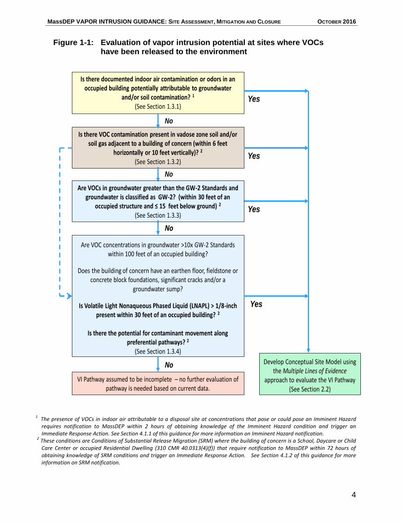
The MCP specifies several conditions that require 2- or 72-hour notification to MassDEP pursuant to 310 CMR 40.0300 based on the presence of OHM in indoor air or the potential of such conditions to result in the discharge of OHM vapors to buildings. These notifications, discussed further in Sections 4.1 and 4.2, trigger the performance of an IRA to expedite the assessment of the potential pathway, and if necessary, remedial action to eliminate or mitigate impacts to receptors. Figure 1-1 illustrates a process for evaluating site information and conditions to determine whether additional assessment of the vapor intrusion pathway is warranted. The different components of this process are discussed in more detail below.
Screening IN v. Screening OUT
This guidance recommends the use of various screening criteria to assist in determining whether a vapor intrusion pathway exists, or is likely to be present. While a single well-placed sample with significant VOC concentrations may be sufficient to indicate the need for further response actions (“screen in” a site for additional investigation), a better understanding of the site conditions that typically includes more sampling data is often necessary to “screen out” sites from further investigation. The investigatory level of effort described herein reflects this difference in screening outcomes.
MassDEP VAPOR INTRUSION GUIDANCE: SITE ASSESSMENT, MITIGATION AND CLOSURE OCTOBER 2016
4
Is there VOC contamination present in vadose zone soil and/or soil gas adjacent to a building of concern (within 6 feet
horizontally or 10 feet vertically)? 2
(See Section 1.3.2)
Is there documented indoor air contamination or odors in an occupied building potentially attributable to groundwater
and/or soil contamination? 1
(See Section 1.3.1)
Are VOC concentrations in groundwater >10x GW-2 Standards within 100 feet of an occupied building?
Does the building of concern have an earthen floor, fieldstone or concrete block foundations, significant cracks and/or a
groundwater sump?
Is Volatile Light Nonaqueous Phased Liquid (LNAPL) > 1/8-inch present within 30 feet of an occupied building? 2
Is there the potential for contaminant movement along preferential pathways? 2
(See Section 1.3.4)
Yes
Yes
No
Develop Conceptual Site Model using the Multiple Lines of Evidence
approach to evaluate the VI Pathway (See Section 2.2)
VI Pathway assumed to be incomplete – no further evaluation of pathway is needed based on current data.
Yes
Yes
No
No
No
Are VOCs in groundwater greater than the GW-2 Standards and groundwater is classified as GW-2? (within 30 feet of an
occupied structure and ≤ 15 feet below ground) 2
(See Section 1.3.3)
1
The presence of VOCs in indoor air attributable to a disposal site at concentrations that pose or could pose an Imminent Hazard requires notification to MassDEP within 2 hours of obtaining knowledge of the Imminent Hazard condition and trigger an Immediate Response Action. See Section 4.1.1 of this guidance for more information on Imminent Hazard notification.
2 These conditions are Conditions of Substantial Release Migration (SRM) where the building of concern is a School, Daycare or Child Care Center or occupied Residential Dwelling (310 CMR 40.0313(4)(f)) that require notification to MassDEP within 72 hours of obtaining knowledge of SRM conditions and trigger an Immediate Response Action. See Section 4.1.2 of this guidance for more information on SRM notification.
Figure 1-1: Evaluation of vapor intrusion potential at sites where VOCs have been released to the environment
MassDEP VAPOR INTRUSION GUIDANCE: SITE ASSESSMENT, MITIGATION AND CLOSURE OCTOBER 2016
5
1.3.1 VOCs in Indoor Air
If the indoor air of an occupied building or structure is sampled and the analytical results indicate that VOCs are present, then there is a potential that vapor intrusion may be occurring. Additional evaluation may be necessary to determine whether the VOCs are disposal site related or from an indoor source (or in some cases a nearby discharge of VOCs to the ambient air). Sampling the indoor air for VOCs without prior groundwater, soil or soil gas data, or a recent release event that indicate the potential for vapor intrusion is not common in the course of a disposal site assessment, but can occur as the result of an investigation of an odor complaint or indoor air quality concern (e.g., by an industrial hygienist). The presence of VOCs in indoor air attributable to a disposal site at concentrations that pose or could pose an Imminent Hazard require notification to MassDEP within 2 hours of obtaining knowledge of the Imminent Hazard condition and trigger an Immediate Response Action. 1.3.2 VOCs in Soil
The MCP (310 CMR 40.0942(1)(d)) states that “If one or more Volatile Organic Compounds is present in the vadose zone soil adjacent to an occupied structure (within six feet, measured horizontally from the wall of the structure, and within ten feet, measured vertically from the basement floor or foundation slab) then the soil has the potential to result in significant indoor air concentrations of OHM and Method 1 alone cannot be used to characterize the risk at the disposal site.”
The concentrations of VOCs in soil at which the potential for vapor intrusion is likely to occur have not been established. The derivation of the MCP Method 1 Soil Standards did not consider the vapor intrusion pathway. In some cases, low concentrations of certain VOCs in soil below the Method 1 Soil Standards could result in an impact to the indoor air of an adjacent building. Consequently, Method 1 alone cannot be used to characterize disposal site risk where there is VOC contamination in soil in the vadose zone near a building. The potential for vapor intrusion must be evaluated if VOCs are detected in soil or soil gas within the distances specified in 310 CMR 40.0942(1)(d).
In some situations, a contaminant source under a building such as a dry well, leaking floor drain or piping, or a VOC spill location can adversely affect soil in the vadose zone without resulting in significant contamination to the underlying groundwater. Soil contamination should be considered a possibility at sites with documented uses of VOCs (such as dry cleaners or industrial facilities using solvents). The investigator should carefully research historical and current chemical use and storage at the site to identify areas where releases to the soil were likely to have occurred. The presence of such potential release locations or screening results or analytical data (e.g., direct measurements of VOCs in soil or of soil gas) indicating VOCs in soil in the vadose zone near or beneath the structure warrant additional evaluation.
MassDEP VAPOR INTRUSION GUIDANCE: SITE ASSESSMENT, MITIGATION AND CLOSURE OCTOBER 2016
6
The distances cited in the MCP (and identified in Figure 1-1) represent the minimum requirements for the evaluation of the vapor intrusion pathway. The presence of contaminated soil or soil gas at greater distances from the building of concern may indicate the need for additional characterization, depending on the concentration of VOCs detected in soil or soil gas, concentration gradients, and the possible presence of preferential migration pathways.
1.3.3 VOCs in Groundwater
The MCP Category GW-2 Standards presented in 310 CMR 40.0974(2) apply to groundwater that is considered a potential source of indoor air contamination via the vapor intrusion pathway. These Standards apply to groundwater that is both shallow (15 feet or less from the ground surface) and near an existing or planned building or structure that is or will be occupied (within 30 feet horizontally). The specific regulatory criteria used to determine the applicability of the GW-2 Standards are described at 310 CMR 40.0932(6).
These Standards are designed to be protective at most sites, and can generally be used as a screening tool to determine whether the potential for vapor intrusion should be further evaluated. The GW-2 Standards should only be used to eliminate the vapor intrusion pathway from further consideration when groundwater is the only potential source of contamination to indoor air. Potential impacts from soil, preferential pathways, or Light Nonaqueous Phase Liquid (LNAPL) should be considered separately.
For the purpose of determining whether further evaluation of the vapor intrusion pathway is warranted, MassDEP recommends (1) that the concentration(s) of VOCs detected in each groundwater sample be compared to the applicable GW-2 Standard, and (2) when contaminant concentrations within GW-2 areas exceed the GW-2 Standards, the vapor intrusion pathway should be further evaluated. The initial step in this investigation would include delineating the extent of groundwater where the VOC concentrations exceed the GW-2 Standards, taking into account location of the source(s), groundwater transport (flow direction and velocity, preferential pathways, etc.), contaminant fate, and location of receptors. Occupied buildings or structures within areas exceeding the GW-2 Standards should be evaluated for the potential vapor intrusion pathway.
In addition, the evaluation should address the potential for increases in the concentrations of VOCs in the groundwater within 30 feet of existing buildings or structures that could result in (a) contaminant concentrations that exceed the GW-2 Standards in the foreseeable future, and/or (b) higher indoor air exposure point concentrations in the foreseeable future.
In cases where a monitoring well has not been or cannot be installed within 30 feet of a building, the location and extent of VOCs concentrations in groundwater above the GW-2 Standards can be extrapolated from an understanding of the source area, groundwater flow direction and groundwater quality using monitoring wells in the vicinity
MassDEP VAPOR INTRUSION GUIDANCE: SITE ASSESSMENT, MITIGATION AND CLOSURE OCTOBER 2016
7
of the building and structures of concern. Through such extrapolation, the need for further evaluation of the vapor intrusion pathway can be determined.
In most, but not all, cases where contaminant concentrations in groundwater are below GW-2 Standards, the investigator can conclude that additional evaluation of vapor migration from groundwater to indoor air is not warranted.
Given that this is a screening evaluation to determine whether conditions exist that warrant further evaluation, averaging concentrations detected in the groundwater from different monitoring wells is not appropriate. Note that this screening use of GW-2 Standards is different from the application of these Standards in an MCP risk characterization, where the nature and extent of OHM concentrations in groundwater and other site conditions must be well characterized in accordance with 310 CMR 40.0904.
VOCs at concentrations that exceed the applicable Groundwater Category GW-2 in groundwater where the average annual depth is 15 feet or less within 30 feet of a building that is a School, Daycare or Child Care Center or occupied Residential Dwelling triggers a 72-hour notification as a Condition of Substantial Release Migration or SRM (310 CMR 40.0313(4)(f)2.). See Section 4.1 for additional discussion of notification requirements and SRM.
1.3.4 Other Factors
Other conditions may be present that indicate the need for a vapor intrusion pathway evaluation, even when groundwater concentrations at the site are below the Method 1 GW-2 Standards and/or the contamination is not within a GW-2 area.
The MCP specifies at 310 CMR 40.0942(1)(b) and 310 CMR 40.0971(1) that if OHM is likely to migrate at significant concentrations to indoor air, then Method 1 alone, including the GW-2 Standards and distance criteria, should not be used to characterize the risk at the site. Common situations where further evaluation of the vapor intrusion pathway is recommended, beyond the screening evaluation based on the GW-2 Standards, include, but are not limited to:
VOC concentrations in groundwater greater than ten times the GW-2 Standard within 100 feet of an occupied building or structure.
Groundwater is not classified as GW-2 in locations with an average annual depth to groundwater greater than 15 feet or where the contaminated groundwater is at a horizontal distance greater than 30 feet from an occupied building. However, findings from existing sites indicate that high contaminant concentrations in groundwater beyond the GW-2 distances may act as a source for indoor air contamination. Therefore, the potential for vapor intrusion resulting from significantly contaminated groundwater outside a GW-2 area should not be dismissed simply because groundwater does not categorically meet the GW-2 definitions. Other regulators at the federal and state level require or recommend
MassDEP VAPOR INTRUSION GUIDANCE: SITE ASSESSMENT, MITIGATION AND CLOSURE OCTOBER 2016
8
an evaluation of groundwater at distances up to 100 feet from buildings when assessing the potential for vapor intrusion for sources other than petroleum hydrocarbons (USEPA, 2015; ITRC, 2007).
The structure of concern has an earthen floor, fieldstone or concrete block wall foundation, significant cracks, and/or a groundwater sump.
These conditions could allow a more direct connection between the interior of the structure and the soil, soil gas and/or groundwater contamination beneath the structure than would be expected with an intact poured concrete foundation. Furthermore, these conditions are not consistent with the assumptions MassDEP used in the derivation of the Method 1 GW-2 Standards.
Volatile petroleum LNAPL is present or is likely to be present within 30 feet (horizontally) of the potentially impacted structure regardless of the depth to groundwater.
The presence of LNAPL is not consistent with the assumptions used in the derivation of the Method 1 GW-2 Standards, and indicates the need for additional evaluation of the vapor intrusion pathway even if groundwater concentrations are less than the GW-2 Standards and the depth to the LNAPL is greater than 15 feet. The presence of volatile LNAPL triggers a 72-hour notification as a Condition of SRM when volatile LNAPL greater than or equal to 1/8 inch is observed in a monitoring well, excavation or subsurface depression within 30 feet of a building that is a School, Daycare or Child Care Center or occupied Residential Dwelling (310 CMR 40.0313(4)(f)3.).
For the purposes of the notification requirement at 310 CMR 40.0313(4)(f)3., MassDEP considers volatile LNAPL to include gasoline, petroleum napthas, mineral spirits, kerosene, and jet fuels. LNAPLs associated with diesel fuels, #2 fuel oils, heavier fuels oils (#3 - #6), waste oils, and lubrication oils are not considered volatile LNAPLs for the purpose of this notification because of their lower VOC content.
VOC contamination is present in preferential pathways, such as utility lines or corridors, which connect to structures of concern.
Contamination may travel from source areas to receptors along preferential pathways such as utility corridors, which could include, but not be limited to, sewer and septic system piping, drains, water and gas lines, electrical conduits, and dry wells. Backfill material in utility corridors is often more porous and permeable than the adjacent native soil. Releases of VOCs in the vicinity of utilities may result in contamination migrating preferentially along these pathways and entering buildings and structures of concern, regardless of the depth to groundwater. This condition also triggers a 72-hour notification as a Condition of SRM when there is evidence of vapor migration along a preferential pathway at a location that is likely to impact the indoor air at a building that is a School,

MassDEP VAPOR INTRUSION GUIDANCE: SITE ASSESSMENT, MITIGATION AND CLOSURE OCTOBER 2016
9
Daycare or Child Care Center or occupied Residential Dwelling (310 CMR 40.0313(4)(f)4.).
The list of conditions above that indicate the need for additional evaluation of the vapor intrusion pathway is not all-inclusive. The LSP should consider site history, site conditions, existing monitoring data and the disposal site Conceptual Site Model (CSM) in making a determination as to whether additional evaluation of the vapor intrusion pathway is warranted.
MassDEP VAPOR INTRUSION GUIDANCE: SITE ASSESSMENT, MITIGATION AND CLOSURE OCTOBER 2016
10
2. ASSESSMENT
This section describes considerations for the assessment of vapor intrusion once the potential for this pathway has been established as described in Section 1. It focuses on assessment activities conducted to determine whether the vapor intrusion pathway at a disposal site is complete and potentially of concern (Section 2.2), conducting an exposure assessment (Section 2.3) and assessment related to risk characterization (Section 2.4), and supporting a Permanent or Temporary Solution.
Assessment activities related to vapor intrusion are conducted for many purposes, such as: determining if a potential vapor intrusion pathway actually exists; providing information suitable for an Imminent Hazard (IH) evaluation; identifying and assessing a Critical Exposure Pathway (CEP); completing a Phase II Comprehensive Site Assessment and Risk Characterization; and evaluating the need for and effectiveness of remedial measures. Assessment activities undertaken for these different purposes will vary depending on the specific assessment and data quality objectives.
In many cases, assessment activities and sampling plans support multiple objectives (e.g., sampling conducted for a Comprehensive Site Assessment may also provide baseline information for planning remedial actions). Assessment plans, be it an IRA Plan, a Phase II Scope of Work, or Phase IV Remedy Implementation Plan (RIP), should clearly present the different objectives of the assessment activities and the rationale for the specific approach selected. In all cases, the performance-based standards for sample collection and analysis at 310 CMR 40.0017 must be followed and the data Quality Assurance/Quality Control (QA/QC) must be commensurate with its intended use.
Assessment of a vapor intrusion pathway should proceed iteratively as disposal site conditions and potential exposure concerns warrant and employ multiple lines of evidence in determining if the vapor intrusion pathway is likely to be of concern. Such assessment may include sampling of groundwater, exterior soil gas,1 sub-slab soil gas, soil, indoor air and outdoor air. Contaminant concentrations in environmental media associated with the vapor intrusion pathway can be highly variable. As such, it is critical to consider spatial and temporal variations of VOC concentrations in groundwater, soil gas, sub-slab soil gas, outdoor air and indoor air and to collect a sufficient amount of samples to address this variability and adequately characterize the pathway; assessment of the vapor intrusion pathway generally warrants a greater amount of data than assessment of other exposure pathways at disposal sites.
1 In this document, “exterior soil gas” refers to soil gas collected in open areas, away from buildings.
These areas could include locations under parking lots and undeveloped lots. Exterior soil gas should not be used as a substitute for sub-slab soil gas when assessing the groundwater to indoor air pathway, but is a useful supplement to soil sampling efforts (see Section 2.1.1).
MassDEP VAPOR INTRUSION GUIDANCE: SITE ASSESSMENT, MITIGATION AND CLOSURE OCTOBER 2016
11
2.1 Conceptual Site Model
The CSM provides a useful tool for characterizing and depicting the source(s) of the oil or hazardous material release to the environment or “Sources of OHM” as that term is defined at 310 CMR 40.0006(12), migration pathways, exposure pathways, and receptors for a specific disposal site, including those relevant to vapor intrusion. It provides a framework for assessing risks from contaminants, controlling or eliminating Sources of OHM, identifying data gaps and managing uncertainty, developing response action strategies, and determining whether those strategies have been effective in achieving desired endpoints. The MCP provides a CSM definition at 310 CMR 40.0006(12). At the point in time at which a vapor intrusion evaluation is initially conducted, the CSM may or may not be fully developed. The CSM available at the time should be used to guide the vapor intrusion evaluation in terms of:
Potential Sources of OHM, including locations and specific OHM used or released at the site;
Nature and extent of OHM impacts;
Known or suspected migration pathways;
Concentrations and distribution of VOCs in soil, groundwater, soil gas, indoor air, and outdoor air, to the extent known; and
Potential indoor air receptors.
The CSM should be continually modified as necessary to incorporate new information collected during the vapor intrusion evaluation and to guide decision-making throughout the process of conducting the disposal site assessment, risk characterization, and remediation process. The complexity of the CSM is directly related to the complexity of disposal site conditions.
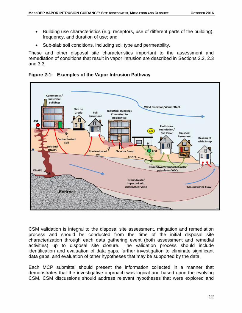
Figure 2-1 shows examples of the vapor intrusion pathway. It is important that the CSM to describe or illustrate other disposal site conditions surrounding the building(s) of interest to provide the context for vapor intrusion. As a vapor intrusion evaluation progresses, conditions specific to the vapor intrusion pathway should be added to the CSM, including:
Known or potential nearby sources;
Concentration of VOCs in the subsurface;
Depth to groundwater and groundwater flow direction;
Buildings potentially impacted by vapor intrusion;
Building characteristics, including such aspects as the presence of a crawl space or basement, slab thickness and condition, heating/air conditioning method and use, supplementary ventilation (bay doors, hoods, etc.), drainage control mechanisms (sumps, floor drain, interior or exterior French drains);
MassDEP VAPOR INTRUSION GUIDANCE: SITE ASSESSMENT, MITIGATION AND CLOSURE OCTOBER 2016
12
Building use characteristics (e.g. receptors, use of different parts of the building), frequency, and duration of use; and
Sub-slab soil conditions, including soil type and permeability.
These and other disposal site characteristics important to the assessment and remediation of conditions that result in vapor intrusion are described in Sections 2.2, 2.3 and 3.3. Figure 2-1: Examples of the Vapor Intrusion Pathway
CSM validation is integral to the disposal site assessment, mitigation and remediation process and should be conducted from the time of the initial disposal site characterization through each data gathering event (both assessment and remedial activities) up to disposal site closure. The validation process should include identification and evaluation of data gaps, further investigation to eliminate significant data gaps, and evaluation of other hypotheses that may be supported by the data. Each MCP submittal should present the information collected in a manner that demonstrates that the investigative approach was logical and based upon the evolving CSM. CSM discussions should address relevant hypotheses that were explored and
MassDEP VAPOR INTRUSION GUIDANCE: SITE ASSESSMENT, MITIGATION AND CLOSURE OCTOBER 2016
13
ruled out, technical justification for adopting one hypothesis over the others, and a statement as to whether or not the objectives of the investigation were achieved. Further discussion of components of the CSM is provided in MassDEP guidance, MCP Representativeness Evaluations and Data Usability Assessments #WSC-07-350 (MassDEP, 2007). 2.1.1 Identification of Sources of OHM
In order to adequately assess the vapor intrusion pathway, locations of where VOCs were released to the environment must be identified. As defined at 310 CMR 40.0006(12), a Source of OHM Contamination is a point of discharge of OHM into the environment, or waste deposits, sludges, or impacted soil, sediment or bedrock at or near a point of discharge/deposit of OHM into the environment that is contaminating surrounding environmental media.
These discharge locations are often the location of the highest concentration of contamination in the soil or groundwater. The identification of Source(s) of OHM requires gathering and understanding, to the extent possible, release and relevant disposal site history information, including how the OHM is, or was, used at the area where the release(s) occurred. Soil, soil gas and groundwater should be sampled at these locations to determine if a release of OHM to the environment has occurred. Soil gas sampling, both from sub-slab and open areas (exterior soil gas), is a useful supplement to soil sampling efforts. While soil sampling targets discrete locations, exterior soil gas samples obtained from multiple soil gas points can be effective in characterizing contamination over a larger area.
Identification and delineation of Sources of OHM that contribute to the vapor intrusion pathway is critical to effective and long-term mitigation of VOC impacts to indoor air. As specified at 310 CMR 40.1003(5)(b), achievement of a Permanent Solution requires that “all Sources of OHM are eliminated, or if they are not eliminated, they are eliminated to the extent feasible and they are controlled …” Locating and delineating Sources of OHM is a necessary step for demonstrating compliance with 310 CMR 40.1003(5)(b) (see also Sections 3.1 and 4.6).
2.2 Vapor Intrusion Pathway Assessment
This section provides guidance on developing appropriate Lines of Evidence for assessing the vapor intrusion pathway for current site use, and how these Lines of Evidence can be used to determine if the pathway is complete and likely to be of concern. Current use is described further in Section 2.3.2. Sources of OHM as defined in the MCP include the point of original discharge or deposit of OHM in the environment. These Sources of OHM may in turn contaminate surrounding environmental media via the processes of dispersion, dissolution, volatilization, advection and diffusion, resulting in the migration of OHM. Where such migration results in VOCs attributable to the release entering into the indoor air of an occupied building, or a building where there are specific plans for occupation, the vapor intrusion pathway is considered complete.
MassDEP VAPOR INTRUSION GUIDANCE: SITE ASSESSMENT, MITIGATION AND CLOSURE OCTOBER 2016
14
MassDEP recommends a Lines of Evidence approach for determining if the vapor intrusion pathway is complete and likely to be of concern. In some cases, a complete pathway is sufficient to warrant further action, such as when a Condition of SRM/CEP is identified. In other cases, risk-based screening values can be used to determine whether the pathway is likely to be of sufficient concern to warrant further action.
The specific Lines of Evidence and the types and amount of data required to draw conclusions regarding a potential vapor intrusion pathway will vary depending upon site conditions and setting. Sampling plans should consider the CSM, including addressing data gaps relevant to evaluating the potential pathway.
MassDEP recommends focusing on a number of major Lines of Evidence for determining whether or not a vapor intrusion pathway is complete and likely to be of concern at a disposal site, including those listed below.
Major Lines of Evidence for the Vapor Intrusion
Concentrations of VOCs in groundwater, soil, and sub-slab and exterior soil gas;
Concentrations of VOCs in indoor air that are Contaminants of Concern;
The presence of VOCs in indoor air from confounding/indoor sources;
The presence of VOCs in outdoor air from confounding/outdoor sources;
The presence of LNAPL or DNAPL; and
The presence of preferential pathways for groundwater/vapor migration.
These major Lines of Evidence are developed through sampling activities and site observations. The Lines of Evidence that are relevant to evaluating a potential pathway and supporting a conclusion as to whether it is complete and of concern will depend on site-specific characteristics. Factors that might influence vapor intrusion, such as specific building characteristics and sub-slab soil type, may be relevant to vapor intrusion assessments, but are not considered major Lines of Evidence.
Individual Lines of Evidence are discussed in more detail below, including where to sample media (location), the length of time to collect samples (collection time), and how often to collect samples (collection frequency) for use as Lines of Evidence. The discussion also includes how to apply such sampling data in a Lines of Evidence evaluation.
2.2.1 Groundwater
Groundwater depth and analytical data are often one of the early indicators of potential vapor intrusion, based on a comparison of the VOC concentration in groundwater to the MCP Method 1 GW-2 Standards established at 310 CMR 40.0974, as discussed in Section 1. As a result, it is a major Line of Evidence to be considered in a vapor intrusion evaluation. However, a vapor intrusion pathway should not be ruled out using groundwater data alone without the consideration of the factors identified in Section 1.3.
MassDEP VAPOR INTRUSION GUIDANCE: SITE ASSESSMENT, MITIGATION AND CLOSURE OCTOBER 2016
15
Groundwater Sampling and Analysis
Groundwater sampling data used in a Lines of Evidence evaluation should be representative of stable site conditions and provide a conservative indication of contaminant concentrations near or under the building(s) of interest, as these groundwater data are most suitable for determining whether the vapor intrusion pathway is likely to be complete.
Groundwater sampling should be conducted to determine the horizontal and vertical extent of contamination and identify areas where groundwater concentrations are sufficient to potentially impact indoor air. Sampling locations should be selected based on knowledge of the disposal site conditions, including the extent of groundwater contamination relative to occupied buildings, depth and proximity of contaminated groundwater relative to occupied buildings, and distance to the Source of OHM Contamination. For determining the extent of contamination, the horizontal distance of sampling locations from the Source of OHM Contamination is a key consideration. To better define contaminant concentrations, the density of sampling locations should be greater in potential area(s) of the release(s), in hot spots, and in close proximity to buildings. Groundwater samples analyzed to evaluate the vapor intrusion pathway should be collected at or near the water table (i.e., 0-2 feet below the water table) and in a manner that ensures that the samples provide VOC concentrations in groundwater representative of the shallowest portion of the aquifer (e.g., using low stress/low flow sampling procedures to extract groundwater immediately below the water table). Water table samples, however, can be diluted by heavy precipitation and should not be collected immediately after heavy rain, or snow melt. Use of groundwater samples obtained at or near the water table to evaluate the vapor intrusion pathway does not mean that deeper groundwater with VOCs at concentrations greater than the GW-2 Standards should be ignored when evaluating the vapor intrusion pathway. Samples obtained from deeper groundwater intervals can provide valuable information regarding the extent of contamination and the potential for contaminants to migrate vertically and/or horizontally. Such migration can contribute to fluctuating VOC concentrations in the shallow groundwater and/or a change in soil vapor concentrations under buildings. Therefore, contaminant concentrations that exceed GW-2 Standard(s) in deeper groundwater, even if the VOC concentrations in the shallow groundwater are less than the GW-2 Standards, might indicate the need for additional evaluation. This may include more frequent temporal sampling of groundwater, evaluating vertical hydraulic gradients, and possibly sub-slab soil gas sampling.
Characterization of contamination in deeper groundwater is also necessary to define the nature and extent of OHM required in a Phase II Comprehensive Site Assessment and as part of the information required to support a Permanent or Temporary Solution. Such information can be used in combination with groundwater flow patterns to identify areas where deeper groundwater contaminated with VOCs migrates to shallower portions of
MassDEP VAPOR INTRUSION GUIDANCE: SITE ASSESSMENT, MITIGATION AND CLOSURE OCTOBER 2016
16
Uncertainty about groundwater contaminant concentrations can be reduced by sufficient sampling frequency over an extended period of time.
the aquifer. Full characterization of nature and extent of OHM will also allow for a more effective remedial approach. Because groundwater flow patterns can vary over time, it is important to obtain seasonal groundwater flow data over several sampling events to capture groundwater flow variability.
The collection of multiple samples over time is more important if the data are to be used to estimate Exposure Point Concentrations (EPCs) than if it will be used to estimate the extent of contamination. Temporal data are needed to detect increasing or decreasing trends and potential seasonal variations in the contaminant concentrations at various sampling locations within the contaminated area. In addition to evaluating a potential vapor intrusion pathway, temporal groundwater data are necessary to demonstrate that response actions have been taken to adequately assess and control the subsurface migration of OHM as required by 310 CMR 40.1003(6) to achieve a Permanent Solution, i.e., demonstrating that plumes of dissolved OHM in groundwater and vapor-phase OHM in the vadose zone are stable or contracting (see also Section 4.6).
Groundwater sampling programs should be designed to evaluate seasonal fluctuations in VOC concentrations and groundwater elevations and may need to be conducted for greater than a year to establish long-term trends in the concentration of VOCs in groundwater and groundwater elevations to determining worst-case conditions for vapor intrusion.
Composite sampling (i.e., combining samples from two or more wells prior to analysis) is not appropriate for groundwater. In order to provide a conservative estimate of exposure, the locations that indicate the greatest potential for vapor intrusion should receive the greater focus of sampling efforts.
Groundwater Data Evaluation
MCP GW-2 Standards were developed using a mathematical screening model developed by Johnson and Ettinger (1991). MassDEP considers the use of this model appropriate for the development of GW-2 Standards because generic, conservative assumptions were used by MassDEP as inputs for the model to cover a wide variety of buildings. Therefore, barring certain site-specific conditions, comparing the concentration of VOCs in the groundwater to the GW-2 Standards can be used in a Lines of Evidence evaluation, as identified in Tables 2-2 and 2-3.
When interpreting groundwater data for petroleum-related compounds, it is important to consider biodegradation within the vadose zone. MassDEP has incorporated this consideration into the development of the GW-2 Standards for petroleum fractions and benzene, toluene, ethylbenzene, and xylenes (BTEX). MassDEP recognizes that there are key differences in evaluating potential vapor intrusion for petroleum compounds and chlorinated solvents. These differences are addressed in more detail in Section 2.2.3.
MassDEP VAPOR INTRUSION GUIDANCE: SITE ASSESSMENT, MITIGATION AND CLOSURE OCTOBER 2016
17
2.2.2 Soil, Exterior Soil Gas and Sub-Slab Soil Gas
Soil, exterior soil gas or sub-slab soil gas data are also major Lines of Evidence to be considered in a vapor intrusion evaluation. High concentrations of VOCs in soil samples obtained from the vadose zone are indicative of a release of VOCs to the environment. However, given the inherent variability associated with sampling soil, exterior soil gas sampling is generally more useful than soil sampling in locating VOC releases to the environment, especially if the history of VOC use at site is unclear. Sub-slab soil gas immediately under the slab of a building is the media in direct contact with a building and the best indicator of the potential for vapor intrusion.
Soil, Exterior Soil Gas and Sub-Slab Soil Gas Sampling and Analysis
Soil
VOC contamination of soil can result in vapor intrusion even when groundwater is not significantly contaminated. However, unless the point of release(s) of VOCs can be identified, accessed, and adequately sampled, soil data are often not a conclusive Line of Evidence for the vapor intrusion pathway.
Soil sampling plans should incorporate historical information documenting the location of machinery, chemical storage areas, etc. Sampling locations to consider for investigation include, but are not limited to:
current and former dry cleaning machine/degreaser locations;
vent locations, including downspouts if the machines vent to the roof;
floor drains;
dry wells;
sewer and septic tank/leach field lines, laterals, cleanouts, and connections;
any current or former solvent/OHM storage areas, including underground and above-ground storage tanks and drum storage areas;
service doors, loading docks or other locations where solvents brought into the building when delivered or removed from the building for disposal;
the location of any current or former solvent distillation or separator units; and
current or former dumpster locations.
The number of soil samples collected will be dependent upon the historical information related to potential release areas, such as those listed above.
MassDEP VAPOR INTRUSION GUIDANCE: SITE ASSESSMENT, MITIGATION AND CLOSURE OCTOBER 2016
18
Soil gas concentrations are generally a better indicator of soil contamination than discrete soil sample data because soil gas data reflect conditions over a larger area.
Exterior Soil Gas
Exterior soil gas samples represent a larger area of the subsurface than soil samples. Therefore, exterior soil gas samples can be useful in identifying Source(s) of OHM Contamination as described in Section 2.1.1, as well as locating and defining areas of soil contamination that have not been identified by discrete soil sample data.
At properties with past or current VOC use, exterior soil gas samples can be used to evaluate potential release locations (such as those listed above as potential soil sampling locations). At sites where the history of VOC use has not been adequately documented, grid sampling of exterior soil gas can be used to identify potential source areas, increasing the likelihood that Source(s) of OHM Contamination have been found. In addition, exterior soil gas surveys can be a useful tool for evaluating the migration of contaminated soil gas in the vadose zone, particularly the migration of vapors along preferential pathways, and guiding monitoring well installations. It is not necessary to collect time-weighted exterior soil gas samples. Short duration grab samples are sufficient. Care should be exercised during sample collection to avoid sampling at too high a rate or via too high a vacuum, as that can create short-circuiting.
The analytical method selected should be based on historical disposal site information and analytical data that identified OHM in other environmental media at the disposal site, but will generally be MassDEP Air-Phase Petroleum Hydrocarbon (APH) method and/or the EPA TO-15 Compendium of Analytical Methods (CAM). Sample density can be increased through the use of a photoionization detector (PID) of sufficient sensitivity for the COCs followed by portable GC or GC/MS analyses.
Soil gas analyte lists should not be limited during initial sampling, prior to establishing the list of the site COCs, because soil gas can sometimes identify VOCs that were released at the site but not documented in the site history or VOCs that may have been missed by soil and groundwater sampling programs. In this respect, soil gas sampling is a good tool to validate the initial CSM. Once all source areas have been identified and the site COCs have been confirmed through validation of the CSM, the analytical list for additional soil-gas samples can be limited to COCs and related/daughter products. The selected list of COCs should be technically justified based on this information and documented in the appropriate MCP submittal.
It is important to note that exterior soil gas concentrations should not be used to assess soil gas concentrations for the purpose of evaluating potential vapor intrusion. Sub-slab soil gas concentrations which are closer to the receptor should be used to evaluate the potential for vapor intrusion.
MassDEP VAPOR INTRUSION GUIDANCE: SITE ASSESSMENT, MITIGATION AND CLOSURE OCTOBER 2016
19
Additional details on exterior soil gas sampling and analysis are presented in Appendix III.
Sub-Slab Soil Gas
Sub-slab soil gas concentrations are a better indicator of vapor intrusion potential than soil data because they characterize a larger area and provide measurements of COCs in the same phase (i.e., vapor) as that potentially present in indoor air when vapor intrusion is occurring. Nevertheless, there can be significant spatial and temporal variability in sub-slab soil gas concentrations, depending on the nature of the local source of vapors, the types of soils beneath the slab, the building characteristics and contaminant migration mechanisms. This variability should be taken into account when developing sampling plans for areas around suspected soil contamination and evaluating sub-slab soil gas results. The distribution of VOCs in soil gas associated with a contaminated soil tends to be more localized than the distribution of VOCs in soil gas from contaminated groundwater. Therefore, more sub-slab soil gas sampling locations may be needed to identify and delineate a potential Source(s) of OHM Contamination in soil or migration pathways.
If VOC concentrations in sub-slab soil gas samples are low or not detected, but elevated concentrations of site-related VOCs are detected within indoor air, it is possible that a localized contaminant source under the building was not identified if the site was not adequately characterized. In such cases, additional assessment would be warranted to better define the CSM and the density of sampling should be commensurate with the size of the building footprint. In some circumstances, sub-slab soil gas can be contaminated through communication with indoor air where VOCs are used in the building of concern. MassDEP recommendations for the collection and analysis of sub-slab soil gas samples are similar to those for exterior soil gas sampling (i.e., the sub-slab soil gas analyte lists should not be limited during initial sampling, time-weighted samples are not necessary, and care should be exercised to avoid short-circuiting during sampling). In addition, MassDEP recommends collecting sub-slab soil gas samples from the airspace immediately below the basement or slab of the building. Soil gas directly beneath a slab or basement is most likely to be representative of what may be migrating into the building. If samples cannot be obtained directly beneath the slab due to access issues, soil gas samples obtained adjacent to the building and under pavement can be used to estimate conditions beneath the building. Sampling adjacent to the building should be performed at a depth below the slab and at an angle such the soil gas under the building footprint is obtained. Collecting data from locations adjacent to the building of interest adds an additional degree of uncertainty to the vapor intrusion assessment at the site and that additional uncertainty must be accounted for in the CSM.
Sub-slab soil gas surveys should address the entire building footprint because soil gas concentrations beneath slabs can vary from point to point. Two to four probes are recommended for a typical single family home; more may be needed in larger buildings or if the concentration of VOCs in the soil or groundwater is relatively high or variable.
MassDEP VAPOR INTRUSION GUIDANCE: SITE ASSESSMENT, MITIGATION AND CLOSURE OCTOBER 2016
20
At least one of the sub-slab soil gas samples should be obtained near the center of the building footprint to offset any type of “edge effect.”
MassDEP recommends a minimum of one to two sub-slab soil gas sampling events. One sampling event might be sufficient to indicate the potential for a complete pathway, but two or more events would be needed to demonstrate that a vapor intrusion pathway is unlikely to be of concern. When conducting two rounds of sub-slab soil gas sampling, it is recommended that the sampling events be conducted over two different seasons. The potential influence of the heating season, changes in groundwater elevation and contaminant concentration fluctuations should be considered when determining the most appropriate sampling times. More sampling events may be warranted if sub-slab soil gas concentrations are highly variable.
Additional details on soil gas sampling and analysis are presented in Appendix III.
Soil, Exterior Soil Gas and Sub-Slab Soil Gas Data Evaluation
MassDEP has developed screening criteria for sub-slab soil gas results that can be used in a Lines of Evidence evaluation of vapor intrusion. These screening criteria are based on indoor air Threshold Values discussed in Section 2.2.4 below and a generic sub-slab soil gas-to-indoor air dilution factor of 70. This generic dilution factor corresponds to the inverse of the 80th percentile of the sub-slab soil gas attenuation factors in the USEPA OSWER’s 2008 vapor intrusion database (USEPA, 2008, Figure 11). The Sub-slab Soil Gas Screening Values (SSGSVs) are provided in Appendix II. In many cases, if VOC concentrations in representative sub-slab soil gas samples are less than the SSGSVs then the vapor intrusion pathway is not likely to be of concern for current disposal site conditions. This conclusion would be contingent on the development of a good CSM, sufficient temporal and spatial sampling and a determination that there is not a preferential pathway from the subsurface to the indoor air (Section 2.2.7).
For the evaluation of sub-slab soil gas concentrations in comparison to the SSGSVs in Appendix II, samples should be analyzed using APH and/or TO-15 CAM methods. (Appendix II values supersede the soil gas screening values in the MassDEP’s Policy #WSC-02-411, Implementation of the MADEP VPH/EPH Approach (2002)). Results from analyses using total organic vapor instruments, such as PIDs and flame ionization detectors (FIDs) are not
Expediting Indoor Air Sampling
In cases where the potential for vapor intrusion has been identified and sampling is targeting a COC that can cause an Imminent Hazard even over a short period of exposure (e.g., trichloroethylene), MassDEP recommends that the indoor air be sampled early in the assessment, even before sampling of the sub-slab soil gas, to expedite the evaluation of whether the pathway is complete and short-term mitigation measures are required (see Section 2.2.4 below). If the COC is detected in the indoor air and confounding indoor sources do not exist, then short-term mitigation measures should be implemented as soon as practicable. If the COC is not among the chemicals detected in the indoor air, then an assessment of the pathway that includes sub-slab soil gas sampling can be resumed.
MassDEP VAPOR INTRUSION GUIDANCE: SITE ASSESSMENT, MITIGATION AND CLOSURE OCTOBER 2016
21
sufficiently chemical-specific to assess vapor intrusion with an appropriate degree of confidence for this purpose.
2.2.3 Special Considerations for the Assessment of Petroleum Vapor Intrusion from Discrete, Well-defined and Stable Petroleum Sources of OHM
For disposal sites with discrete and well-defined sources of petroleum, the Inclusion Distance Approach (IDA) (USEPA, 2013) provides a screening tool to help distinguish between petroleum disposal sites that require additional data collection and those where vapor intrusion is unlikely to be a pathway of concern. The basis of the IDA is the understanding that petroleum hydrocarbons (PHCs) are readily degraded in the vadose zone under normal aerobic conditions by native microbiotic communities.
Petroleum concentrations in soil gas will generally degrade over time as distance from the source increases. Degradation of petroleum contamination sufficient to avoid impacts to indoor air does not occur at all sites; high concentrations of dissolved contaminants or LNAPL in direct contact with building structures can result in a complete petroleum vapor intrusion (PVI) pathway.
USEPA’s IDA is based on the observed attenuation of benzene and other PHCs over a distance beyond which there is limited potential for a vapor intrusion pathway. The IDA consists of an analysis of the thickness of biologically active clean soil required for the vapor concentrations to attenuate to below levels of concern for vapor intrusion. According to data obtained by USEPA, this distance is generally less than 6 feet for dissolved PHCs and generally less than 15 feet when LNAPL is present.
USEPA’s IDA only applies to sites with stable, discrete petroleum sources and an oxygenated vadose zone that are properly characterized. The full extent and location of contamination must be established so that lateral and vertical separation distances can be accurately determined.
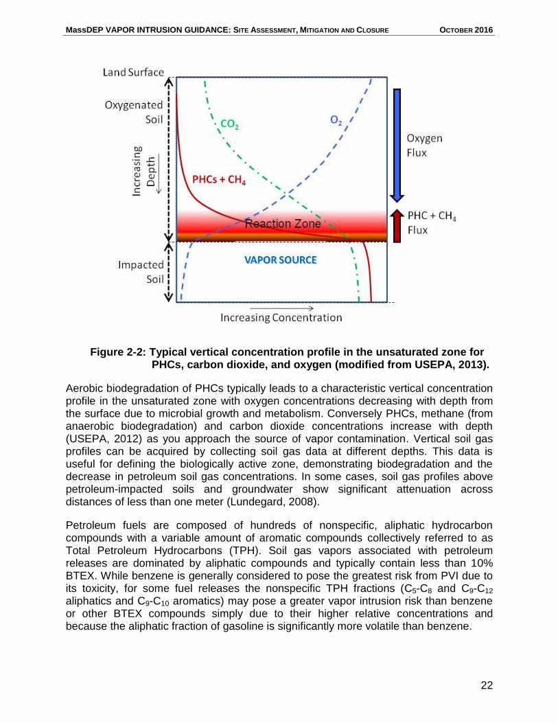
During aerobic biodegradation in unsaturated soils, PHCs are degraded, oxygen is consumed, and carbon dioxide is produced (Figure 2-2). Under some conditions, aerobic biodegradation of petroleum compounds can have half-lives as short as hours or days (DeVaull, 2007). However, if PHC concentrations are high enough, available oxygen may be depleted, which in turn limits aerobic biodegradation.
MassDEP VAPOR INTRUSION GUIDANCE: SITE ASSESSMENT, MITIGATION AND CLOSURE OCTOBER 2016
22
Aerobic biodegradation of PHCs typically leads to a characteristic vertical concentration profile in the unsaturated zone with oxygen concentrations decreasing with depth from the surface due to microbial growth and metabolism. Conversely PHCs, methane (from anaerobic biodegradation) and carbon dioxide concentrations increase with depth (USEPA, 2012) as you approach the source of vapor contamination. Vertical soil gas profiles can be acquired by collecting soil gas data at different depths. This data is useful for defining the biologically active zone, demonstrating biodegradation and the decrease in petroleum soil gas concentrations. In some cases, soil gas profiles above petroleum-impacted soils and groundwater show significant attenuation across distances of less than one meter (Lundegard, 2008).
Petroleum fuels are composed of hundreds of nonspecific, aliphatic hydrocarbon compounds with a variable amount of aromatic compounds collectively referred to as Total Petroleum Hydrocarbons (TPH). Soil gas vapors associated with petroleum releases are dominated by aliphatic compounds and typically contain less than 10% BTEX. While benzene is generally considered to pose the greatest risk from PVI due to its toxicity, for some fuel releases the nonspecific TPH fractions (C5-C8 and C9-C12 aliphatics and C9-C10 aromatics) may pose a greater vapor intrusion risk than benzene or other BTEX compounds simply due to their higher relative concentrations and because the aliphatic fraction of gasoline is significantly more volatile than benzene.
Figure 2-2: Typical vertical concentration profile in the unsaturated zone for PHCs, carbon dioxide, and oxygen (modified from USEPA, 2013).
MassDEP VAPOR INTRUSION GUIDANCE: SITE ASSESSMENT, MITIGATION AND CLOSURE OCTOBER 2016
23
At a limited number of sites, MassDEP has seen aliphatic fraction concentrations drive vapor intrusion risks, indicating that for sites with gasoline or middle distillate (e.g., diesel) fuel releases, or releases which may contain high concentrations of nonspecific C5-C8 and C9-C12 aliphatics and/or C9-C16 aromatics fractions, the IDA may not be sufficient for ruling out PVI. Additional soil gas profiling to quantify the volatile aliphatic hydrocarbon ranges using MassDEP’s APH Method can be used to evaluate whether such fractions (in comparison to the SSGSV in Appendix II) pose a vapor intrusion risk.
When using USEPA’s IDA, the goal should be to collect sufficient information to confirm that levels of petroleum in shallow soil vapor do not pose an unacceptable risk by the vapor intrusion pathway.
Steps that would be required to apply the IDA include, but are not limited to:
1. A comprehensive disposal site investigation to identify the nature and extent of contamination.
2. A review of disposal site conditions to confirm that no exclusionary conditions exist.
3. Sufficient data collection to support conclusion that source is discrete, stable and is comprised of PHCs only.
4. Development of the Conceptual Site Model.
5. Adequate vertical soil gas profiling to characterize the biodegradation reaction zone, including evidence of an oxygenated vadose zone.
6. A review of soil vapor data for the presence of elevated nonspecific TPH fractions.
Conditions that may preclude the use of IDA include:
large scale petroleum operations (e.g., fuel terminals)
presence of > 20% gasoline additives (e.g., ethanol) which can result in methane production and reduce oxygen availability
presence of chlorinated compounds
presence of volatile lead scavengers (e.g., ethylene dibromide)
presence of preferential pathways
high organic soil content (e.g., peat) which can reduce oxygen availability
exceptionally dry soils (≤ 2% soil moisture) which can limit biological activity
extensive impervious surfaces resulting in low soil moisture (while conditions vary from site to site, there can be reduced oxygen availability below hard surfaces (USEPA, 2013))
reduced oxygen flux in certain geologic conditions (e.g., wet surface clays)
MassDEP VAPOR INTRUSION GUIDANCE: SITE ASSESSMENT, MITIGATION AND CLOSURE OCTOBER 2016
24
Items suspected of containing chemicals of concern should be removed prior to the sampling of indoor air. Failure to remove such items may make it necessary to
conduct additional sampling that otherwise could have been avoided.
contaminant migration through fractured rock (there is limited PVI data for these site conditions thereby increasing the uncertainty of the suitability of the IDA)
coarse sand and gravel with a low content of silt, clay, or organic matter
consolidated rock with solution channels (i.e., karst)
In cases where the IDA approach is not applicable, the more standard Lines of Evidence approach (using groundwater, sub-slab soil gas and indoor air data) should be used to evaluate the potential vapor intrusion pathway.
2.2.4 Indoor Air
Indoor air measurements as a Line of Evidence should be given substantial weight when evaluating the vapor intrusion pathway, since they provide a direct measure of contaminant concentrations in indoor air at the time of the sampling. If disposal site-related contaminants (i.e., COCs present in groundwater, soil, exterior soil gas and/or sub-slab soil gas) are not detected in indoor air over multiple rounds of testing, the existence of a complete vapor intrusion pathway is unlikely. If contaminants detected in the sub-surface are detected in indoor air, it may be reasonable to conclude that the vapor intrusion pathway is complete.
Indoor Air Sampling and Analysis Indoor air analytical data relevant to evaluating whether the vapor intrusion pathway is complete and likely to be of concern should generally be biased toward those locations most likely to be impacted by VOCs attributable to the disposal site, such as basements, crawlspaces, or other areas closest to potential vapor source(s) and migration pathways, and collected when conditions are most conducive to vapor intrusion based on the CSM. It may be difficult to rule out the pathway without such data, especially if other Lines of Evidence suggest the potential for vapor intrusion.
Consideration of other sources that may be contributing VOCs to indoor are which are not associated with the disposal site (a.k.a. confounding sources) is important to the evaluation of indoor air as a Line of Evidence. When sampling indoor air, efforts should be made to eliminate confounding sources of contamination within or near the building. These efforts may include:
Conducting indoor air sampling while VOC-generating activities are not occurring, especially if the VOCs generated by those activities are the same as the disposal site-related COCs. For example, collect air samples on days when a nearby dry cleaner is not using the dry cleaning machines or when adjacent gas stations are not being re-fueled. Smoking and use of sprays, solvents, paints, etc. should be noted and, if practicable, suspended 48 hours prior to sampling.
MassDEP VAPOR INTRUSION GUIDANCE: SITE ASSESSMENT, MITIGATION AND CLOSURE OCTOBER 2016
25
Removing items that might contain the same VOCs as the disposal site-related COCs. Examples of these sources include recently dry-cleaned clothing, solvents or other similar products. Products that contain VOCs should be removed at least 48 hours prior to sampling.
Evacuated canisters are recommended for the collection of indoor air samples for the analysis of petroleum-based and chlorinated organic contaminants encountered at most disposal sites.
The collection of indoor air samples should occur while people are using the building for its intended purpose and the duration of the sampling should be based on collecting samples that are representative of the exposure to the residents/occupants of the building. For residential buildings, MassDEP recommends a 24-hour sampling time period using evacuated canisters. A 24-hour sample captures the fluctuations in indoor air concentrations due to changing conditions throughout the day and night. Longer sampling periods generally provide more representative exposure data, but are sometimes not practical. For commercial buildings, MassDEP recommends an 8-hour sampling period during regular business hours, except where regular business activities would potentially contribute VOCs to the indoor air from confounding sources.
If both sub-slab and indoor air sampling is planned at a building, the sub-slab samples should be obtained immediately following the collection of indoor air samples. Sampling sub-slab soil gas immediately after indoor air will both avoid potential cross-contamination from opening the sub-slab sampling probes prior to indoor air sampling, and provide comparable indoor air and sub-slab soil gas samples that were obtained within a similar timeframe and under similar site conditions.
MassDEP recommends multiple rounds of indoor air sampling across several seasons in order to address the considerable temporal variability associated with vapor intrusion. At least one sampling event should be conducted during worst-case conditions. Worst-case conditions should be identified when developing the disposal site CSM. Worst-case conditions are generally thought to occur during winter, when windows are usually closed and heating systems are more active, factors conducive to vapor intrusion. MassDEP also recommends sampling when the groundwater elevation is high and during a low pressure event. Table 2-1 presents site conditions that are most likely to represent worst-case scenarios.
MassDEP recommends greater sampling frequency for more sensitive receptors. For daycares, schools, residences, or other locations where sensitive receptors may be present, MassDEP recommends that at least two to four rounds of indoor air samples be collected, depending on the degree of subsurface contamination, before determining that the vapor intrusion pathway does not exist.
For commercial and industrial buildings where sensitive receptors are not present, at least two indoor air sampling rounds are recommended to provide sufficient information to make decisions regarding the presence of the vapor intrusion pathway. In order to
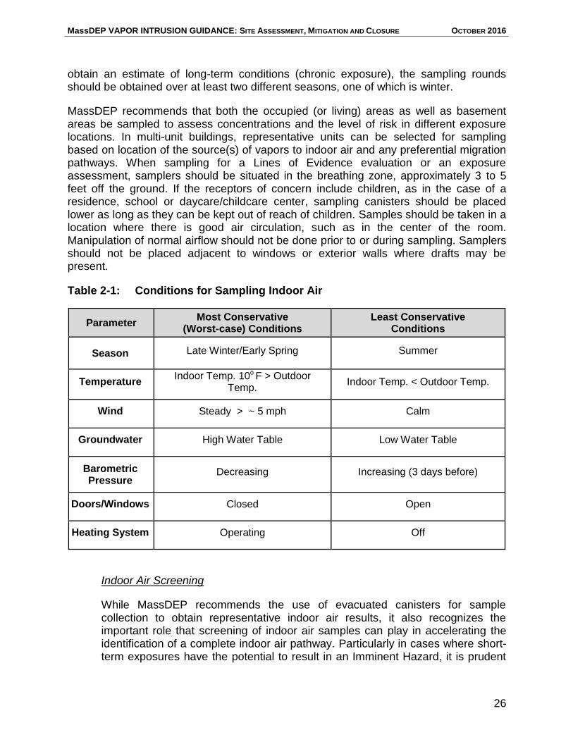
MassDEP VAPOR INTRUSION GUIDANCE: SITE ASSESSMENT, MITIGATION AND CLOSURE OCTOBER 2016
26
obtain an estimate of long-term conditions (chronic exposure), the sampling rounds should be obtained over at least two different seasons, one of which is winter.
MassDEP recommends that both the occupied (or living) areas as well as basement areas be sampled to assess concentrations and the level of risk in different exposure locations. In multi-unit buildings, representative units can be selected for sampling based on location of the source(s) of vapors to indoor air and any preferential migration pathways. When sampling for a Lines of Evidence evaluation or an exposure assessment, samplers should be situated in the breathing zone, approximately 3 to 5 feet off the ground. If the receptors of concern include children, as in the case of a residence, school or daycare/childcare center, sampling canisters should be placed lower as long as they can be kept out of reach of children. Samples should be taken in a location where there is good air circulation, such as in the center of the room. Manipulation of normal airflow should not be done prior to or during sampling. Samplers should not be placed adjacent to windows or exterior walls where drafts may be present.
Table 2-1: Conditions for Sampling Indoor Air
Parameter Most Conservative (Worst-case) Conditions
Least Conservative Conditions
Season Late Winter/Early Spring Summer
Temperature Indoor Temp. 10o F > Outdoor
Temp. Indoor Temp. < Outdoor Temp.
Wind Steady > ~ 5 mph Calm
Groundwater High Water Table Low Water Table
Barometric Pressure
Decreasing Increasing (3 days before)
Doors/Windows Closed Open
Heating System Operating Off
Indoor Air Screening
While MassDEP recommends the use of evacuated canisters for sample collection to obtain representative indoor air results, it also recognizes the important role that screening of indoor air samples can play in accelerating the identification of a complete indoor air pathway. Particularly in cases where short-term exposures have the potential to result in an Imminent Hazard, it is prudent
MassDEP VAPOR INTRUSION GUIDANCE: SITE ASSESSMENT, MITIGATION AND CLOSURE OCTOBER 2016
27
to expedite the collection and analysis of indoor air samples if sensitive receptors use/reside in the building under investigation. The screening of indoor air samples using a portable gas chromatograph/mass spectrometer (GC/MS) allows the investigator to determine within a few hours if an IH is likely2, and in turn, to implement actions to reduce indoor air impacts and/or relocate sensitive receptors more quickly. Indoor air screening can substantially expedite an investigation of vapor intrusion that involves multiple buildings; same day results allow for better decision-making in the field, and can save considerable time and money and maximize the information gathered during each sampling event.
Screening should be conducted in conjunction with collecting samples for laboratory analysis using evacuated canisters to allow for comparison and confirmation of the screening results.
The method(s) selected for analysis of samples should be based on a thorough disposal site history relative to the use of OHM and information on contaminants detected in other site media. Generally MassDEP’s Air-Phase Petroleum Hydrocarbons (APH) (WSC-CAM-IX A) and/or Volatile Organic Compounds in Air Samples (TO-15) (WSC-CAM-IX B) air methods should be used.
Analyzing the indoor air for the full method target analyte list has the benefit of providing building occupants with information regarding their general exposure to chemicals in the indoor air. The indoor air analyte list may be limited to the group of chemicals known to be or likely to be disposal site-related based on the site history and the documented presence (or absence) of these contaminants as confirmed through robust sampling and analysis of other site media (groundwater, soil, and soil gas). For example, if tetrachloroethylene (PCE) has been identified from the site use, release history and analysis of other media as the primary Contaminant of Concern, the analyte list may be limited to chlorinated solvents. The analysis should not be limited to PCE alone, however, since many other chlorinated solvents are often associated with PCE as either breakdown products or present as part of the manufacturing process. The justification for the selected analyte list should be documented in the applicable sampling plan.
Additional guidance on conducting indoor air sampling and analysis is presented in Appendix III.
Indoor Air Data Evaluation
The evaluation of indoor air data can be complex due to the many factors that can affect vapor intrusion and indoor air quality. The detection of disposal site-related OHM in indoor air is an indicator that a complete vapor intrusion pathway may exist. The
2 MassDEP has conducted on-site indoor air analysis on samples collected in 1-Liter sampling bags over
a short duration time period (approximately 2 minutes). With this approach, MassDEP is able to run up to 25 samples per day and obtain results within a few hours from the time of sample collection (Fitzgerald, 2016).
MassDEP VAPOR INTRUSION GUIDANCE: SITE ASSESSMENT, MITIGATION AND CLOSURE OCTOBER 2016
28
The absence of breakdown products and/or disposal site-related VOC concentration gradients in indoor air should not be used alone to rule out the
vapor intrusion pathway.
presence in indoor air of breakdown products of OHM known to be disposal site-related may also be indicative of a complete vapor intrusion pathway. The absence of breakdown products in indoor air, however, should not be used to rule out the pathway. While in theory, dilution factors for breakdown products should be the same as those for the parent compound. In practice, the spatial variation in sub-slab parent/daughter concentrations makes the evaluation of breakdown products as a Line of Evidence difficult.
Comparisons of concentrations of disposal site-related VOCs between the basement and the first floor can in some cases be misleading. Higher concentrations of a disposal site-related chemical in a basement compared to the first floor suggest that vapor intrusion may be occurring. However, the absence of such a concentration gradient should not be used to rule out the pathway before considering possible preferential pathways, and other factors that can influence air movement within a building (such as the heating, venting, and air conditioning (HVAC) system, ventilation fans, etc.), and result in higher COC concentrations on upper levels of a building. The potential for such factors to complicate the evaluation of indoor air data underscores why developing empirical Lines of Evidence and a robust CSM are important in understanding and assessing the vapor intrusion pathway.
Indoor Air Threshold Values
To simplify the process of evaluating whether the vapor intrusion pathway is complete and likely to be of concern, MassDEP has developed Residential and Commercial/Industrial Threshold Values (TVs) for indoor air. The derivation of the TVs is outlined in Appendix I. TVs can be used as one of the Lines of Evidence to evaluate the vapor intrusion pathway.
Residential Threshold Values (TVr) are intended to expedite and support the evaluation of indoor air data collected as part of MCP response actions in residential settings. TVr are based on indoor air data from residences unaffected by vapor intrusion provided in MassDEP’s technical update titled Residential Typical Indoor Air Concentrations (MassDEP, 2008), MCP risk management criteria and the analytical Reporting Limit for the chemical. It can generally be concluded that representative residential indoor air samples with VOC concentrations less than their TVr, and therefore less than the concentration that would be anticipated in the absence of the disposal site, indicate that the vapor intrusion pathway is unlikely to be of concern under current site conditions and use.
The Commercial/Industrial Threshold Values (TVc/i) are largely risk-based using typical exposure scenarios for commercial/industrial settings. Similar to Residential Threshold Values, it can generally be concluded that representative indoor air samples with contaminant concentrations in commercial/industrial settings less than their TVc/I
MassDEP VAPOR INTRUSION GUIDANCE: SITE ASSESSMENT, MITIGATION AND CLOSURE OCTOBER 2016
29
indicate that that the vapor intrusion pathway is unlikely to be of concern under current site conditions and use.
If VOC concentrations in the indoor air exceed the applicable TVs, then this Line of Evidence suggests that vapor intrusion may be a pathway of concern and additional evaluation is warranted. Any investigation which concludes that indoor air VOC concentrations greater than the TVs are not from vapor intrusion should be technically justified using additional Lines of Evidence. Such justification should demonstrate that the VOCs detected in the indoor air are not disposal site-related. Lines of Evidence for this demonstration may include a comparison of the concentration of VOCs in indoor air to VOCs in outdoor (ambient) air to determine if VOCs in indoor air may be resulting from exchange with outdoor air (see Section 2.2.5). The identification of indoor sources (such as building materials) of the specific contaminants of concern may also be a relevant Line of Evidence and should be appropriately evaluated. Household Products, Commercial Products and Building Materials
“Household products,” including cleaning products containing VOCs used and/or stored in a residence are relatively common sources of indoor air contaminants. Many of these products are also used in office and commercial and industrial buildings. A list of household products and activities that potentially contain VOCs can be found at http://householdproducts.nlm.nih.gov/. Additionally, materials used in building construction can be a source of VOCs to indoor air. If a building material is suspected of being a source of VOCs in indoor air, the chemical constituents should either be confirmed using documentation such as Safety Data Sheets or by directly testing the material. Surveying and documenting items that could contain VOCs is an essential part of an indoor air sampling program. As discussed previously, to the extent possible, items that contain the same VOCs that are COCs at the disposal site should be removed at least 48 hours before sampling the indoor air.
In some cases, indoor air may be affected by an indoor air source with a contaminant that is not referenced in the Typical Indoor Air Concentrations. The indoor source should be documented and quantified to the extent possible to support conclusions that the contaminant(s) in indoor air is not disposal site-related.
2.2.5 Outdoor Air
The quality of outdoor air can affect the concentrations of VOCs in indoor air. Consideration of ambient air concentrations as a Line of Evidence is recommended when indoor air VOC concentrations are being evaluated to determine if the vapor intrusion pathway is complete and likely to be of concern.
Outdoor Air Sampling and Analysis
Outdoor sources of pollution can affect indoor air quality due to the exchange of outdoor and indoor air in buildings through natural ventilation, mechanical ventilation or infiltration. Ambient air sampling for the purposes of a Lines of Evidence evaluation is
MassDEP VAPOR INTRUSION GUIDANCE: SITE ASSESSMENT, MITIGATION AND CLOSURE OCTOBER 2016
30
Indoor air impacted by outdoor air that has been affected by reportable OHM releases to the environment warrant response actions under the MCP.
useful, particularly if an outdoor source of disposal site-related chemicals is known or suspected. While sampling near any such outdoor sources may provide useful information, determining the concentration of VOCs in the outdoor air in close proximity to the building under investigation is most relevant to assessing the influence of outdoor air on indoor air in a Lines of Evidence evaluation.
Outdoor air samples should be collected and analyzed by the same method as the indoor air samples. MassDEP recommends a 24-hour sampling time period using evacuated canisters. Additional guidance air sampling and analysis are presented in Appendix III.
Assessing spatial variability in outdoor air is difficult. Considerations for outdoor air sampling should include the existence and location of potential sources of VOCs that may affect outdoor air quality (e.g., automobiles, lawn mowers, oil storage tanks, gasoline stations, industrial facilities). If possible, outdoor activities that may contribute to VOCs in the outdoor air (lawn mowing, painting, asphalt paving, etc.) should be suspended during sampling.
Outdoor Air Data Evaluation
If the concentration of site-related VOCs in indoor air are clearly consistent with outdoor air concentrations of the same VOCs, then it is possible that the VOCs detected in the indoor air is not related to vapor intrusion from the disposal site. Consideration should be given to whether or not the activities that contribute to the confounding outdoor air sources were on-going or in operation during the sampling event. If the activities that were contributing VOCs to the outdoor air were suspended during sampling, then the VOCs detected in the indoor air may be from vapor intrusion from the site. Conditions that contribute VOCs to the outdoor air should be documented such that the appropriate conclusions may be drawn.
There may be disposal site-related VOCs affecting the indoor air via the outdoor air. Examples include recent VOC releases to soil or pavement, and VOC-contaminated soil piles. Such contamination warrants response actions to address the impact to indoor air and can confound the evaluation of potential vapor intrusion from the subsurface environment. Therefore, to the extent possible, measures to mitigate disposal site conditions that are impacting or potentially impacting ambient air should be implemented prior to conducting a vapor intrusion pathway evaluation.
MassDEP VAPOR INTRUSION GUIDANCE: SITE ASSESSMENT, MITIGATION AND CLOSURE OCTOBER 2016
31
Pursuant to 310 CMR 40.1003(7), a Permanent or Temporary Solution shall not be achieved at a disposal site where NAPL is or was visibly present at levels requiring
notification under the provisions of 310 CMR 40.0300 unless and until response actions are taken to adequately assess the nature, extent, and mobility of the NAPL, and, where necessary, remedial actions are taken to adequately contain or remove such NAPL. This requirement applies regardless of the potential for NAPL to result
in vapor intrusion.
2.2.6 Non-Aqueous Phase Liquids
The presence of volatile LNAPL can represent a significant source of vapors to indoor air that may not be reflected in dissolved phase OHM detected in groundwater and/or soil. The CSM and interpretation of Lines of Evidence should consider the presence of LNAPL, even when the concentrations of VOCs in detected in the groundwater and/or soil suggest that vapor intrusion is unlikely to be a pathway of concern.
As stated in Section 1, for the purposes of the notification requirements established at 310 CMR 40.0313(4)(f)(3), volatile LNAPL includes gasoline, petroleum napthas, mineral spirits, kerosene, jet fuels, any petroleum mixture where more than 25 percent of component hydrocarbons (by mass) have a boiling point below 218ºC (424ºF), and any single component (or predominantly single-component) LNAPL with a boiling point below 218ºC. Because of their lower VOC content, diesel fuels, #2 fuel oils, heavier fuels oils (#3 - #6), waste oils and lubrication oils are not subject to the notification requirements pursuant to 310 CMR 40.0313(4)(f)(3), however, these LNAPLs do contain some volatile components and as part of the assessment to support the Phase II Comprehensive Site Assessment, and as required by 310 CMR 40.0835(4)(e)(3), an evaluation of the potential for this type of LNAPL to be a source of vapors of OHM to indoor air of occupied structures must be conducted.
Where other sources have been ruled out, the presence of Dense Non-Aqueous Phase Liquids (DNAPL) is generally indicated by persistently high VOC concentrations in groundwater over time. The presence of DNAPL can result unpredictable fluctuations in groundwater contaminant concentrations and in greater uncertainty in characterizing VOC plumes in groundwater and trends in the concentration of VOCs. This unpredictability should be addressed in sampling plans and an adequate number of sampling events, and accounted for in the CSM.
2.2.7 Preferential Pathways
The potential presence of preferential pathways for the migration of VOCs from the environment to indoor air should be considered in a Lines of Evidence evaluation. Preferential pathways can include elevator shafts, sumps, floor drains, improperly constructed plumbing fixtures, extensive cracks that extend through the slab or foundation and annular spaces around the entrance point(s) of utility lines (e.g., water
MassDEP VAPOR INTRUSION GUIDANCE: SITE ASSESSMENT, MITIGATION AND CLOSURE OCTOBER 2016
32
pipes, sewer/septic pipes, and gas, electric and communication lines) that connect the subsurface environment and/or sub-slab air space directly to indoor air. As direct routes for the migration of VOCs, preferential pathways have the potential to significantly impact indoor air. Soil gas screening values and GW-2 Standards do not account for the direct connection provided by a preferential pathway between soil gas and indoor air.
Although total organic vapor instruments, such as PIDs, are not sufficiently chemical-specific to provide a definitive analysis of sub-slab soil gas concentrations, they are very useful in identifying preferential pathways. These instruments can be used, for example, to screen air migrating through openings in the basement walls and slab. A field GC/MS can also be used to evaluate preferential pathways and has the added advantage of being able to identify specific compounds in the air.
Private Water Supply Wells as Route for VOCs to Indoor Air
VOCs in groundwater that have impacted a private water supply well can constitute a route for vapor intrusion resulting from the volatilization of VOCs in the water being supplied to the building into the indoor air. Indoor air impacts can occur even if the concentrations of VOCs are well below the GW-2 Standards. This could be of particular concern in a residence and other buildings where showering in VOC-contaminated water is occurring as the showering activity aerates the water causing greater volatilization of the VOCs.
2.2.8 Lines of Evidence Interpretation for the Presence of a Current Vapor Intrusion Pathway
Conclusions regarding whether or not the vapor intrusion pathway is complete and likely to be of concern under current site uses should be supported by sufficient and appropriate Lines of Evidence. To aid in the interpretation of Lines of Evidence, MassDEP has developed Line of Evidence matrices applicable to: residences, schools, and daycares; and industrial/commercial buildings. These matrices, presented in Tables 2-2 and 2-3 respectively, consider VOC concentrations in groundwater, sub-slab soil gas, and the indoor air in developing conclusions regarding whether the vapor intrusion pathway is complete and likely to be of concern. The matrices apply to scenarios under which the potential for vapor intrusion has already been identified, as described in Section 1.
Data used for a Lines of Evidence evaluation of whether a vapor intrusion pathway is complete should be representative of site conditions and account for seasonal and other time-related variability. Data evaluated using Tables 2-2 and 2-3 should not be averaged across different sampling locations. Additionally, averaging the results of samples from the same location over time is appropriate only when concentrations are
Data used in a Lines of Evidence evaluation should be representative of current conditions and not averaged over sampling locations.
MassDEP VAPOR INTRUSION GUIDANCE: SITE ASSESSMENT, MITIGATION AND CLOSURE OCTOBER 2016
33
consistent and an adequate number of samples are used. Justification should be provided for eliminating sampling results from the evaluation.
Tables 2-2 and 2-3 reflect the major Lines of Evidence for determining whether the pathway is complete and of concern: the concentration of VOCs in groundwater, sub-slab soil gas and indoor air. Vapor intrusion evaluations are best conducted using all three of these Lines of Evidence. MassDEP understands that there are situations where it is difficult to collect indoor air samples and circumstances when consideration of Lines of Evidence other than groundwater, sub-slab soil gas and indoor air are important. Recommendations provided in Tables 2-2 and 2-3 are based on the assumption that the site characterization, including a survey of potential preferential pathways, is appropriate and adequate. Decisions to consider or exclude other Lines of Evidence should be based on the CSM, and technically justified and documented.
In applying the Lines of Evidence matrices, if it is concluded that the vapor intrusion pathway is not likely to be a concern under current conditions and uses, then generally no additional evaluation is necessary. However, in situations where indoor air has not been sampled and the concentration of VOCs in groundwater and sub-slab soil gas are low (≤ GW-2 Standards and ≤ SSGSVs, respectively), the possibility of a preferential migration pathway should be considered before concluding that the vapor intrusion pathway is not likely to be of concern. If through applying the Lines of Evidence matrix the vapor intrusion pathway is determined to be complete and likely to be a concern, additional response actions must be taken to address any CEP in a residential, school or daycare setting, or potential exposure in commercial/industrial settings.
The matrix presented in Table 2-3 should be used with caution when conducting a vapor intrusion assessment at commercial or industrial locations that use the same VOCs as the site-related COCs as part of ongoing operations (e.g., dry cleaners, gasoline filling stations, etc.). Comparing the concentration of VOCs in the indoor air to the TVs has limited utility in these situations because it is difficult to determine what portion of indoor air contamination, if any, is the result of vapor intrusion. For these locations, greater weight should be given to other Lines of Evidence such as the concentration of VOCs in the subsurface and outdoor air. For example, if VOC concentrations in sub-slab soil gas are below SSGSVs, then it is unlikely that a complete pathway of concern exists (310 CMR 40.0926(7)(a)2), even if indoor air concentrations exceed TVs.

MassDEP VAPOR INTRUSION GUIDANCE: SITE ASSESSMENT, MITIGATION AND CLOSURE OCTOBER 2016
34
Table 2-2: Interpreting Lines of Evidence for Presence of Current Exposure Pathways at Residences, Schools and Daycares
Lines of Evidence
Groundwater
Contaminant Levels
≤ GW-2
AND
> GW-2
OR
Sub-Slab Soil Gas
Contaminant Levels a
≤ Screening Criteria
AND
> Screening Criteria
AND
Indoor Air Contaminant
Levels
Not Tested ≤ TVr > TVr ≤ TVr > TVr
Likely Current Pathway
of Concern?
No No See
Footnote b
No Yes
Notes for Tables 2-2 and Table 2-3:
TVr - Refers to Residential Indoor Air Threshold Values contained in Appendix I. TVc/i - Refers to Commercial/Industrial Indoor Air Threshold Values contained in Appendix I. a - Sub-Slab Soil Gas Screening Values (SSGSVs) provided in Appendix II. b - Evaluate potential indoor air sources and/or preferential migration pathways. Indoor air results
are not consistent with low subsurface contamination, which raises the possibility of indoor air source(s), preferential pathway(s), or unidentified subsurface sources related to a release. Consult with MassDEP on ambiguous results.
Table 2-3: Interpreting Lines of Evidence for Presence of Current Exposure Pathways at Commercial/Industrial Locations
Lines of Evidence
Groundwater Contaminant Levels
≤ GW-2
AND
> GW-2
OR
Sub-Slab Soil Gas Contaminant
Levels a
≤ SSGSVs
AND
> SSGSVs
AND
Indoor Air Contaminant Levels Not Tested ≤ TVc/i > TVc/i ≤ TVc/i > TVc/i
Likely Current Pathway of
Concern? No No See Footnote
b No Yes
MassDEP VAPOR INTRUSION GUIDANCE: SITE ASSESSMENT, MITIGATION AND CLOSURE OCTOBER 2016
35
There may be a concern about the health risk associated with exposure to a non-disposal site related contaminant in indoor air. However, such contaminants are not
considered COCs and are not regulated by M.G.L. c. 21E or the MCP.
An exposure assessment must be conducted to provide “… a conservative estimate of the exposure to oil and/or hazardous material which a receptor may receive within
the contaminated area over a period of time” (310 CMR 40.0920).
2.3 Indoor Air Exposure Assessment
Where it has been determined that the vapor intrusion pathway is a pathway of concern, exposure assessments must be conducted to characterize any Imminent Hazards, Substantial Hazards (310 CMR 40.0950), and to establish whether a level of No Significant Risk (NSR) to human health exists or has been achieved (310 CMR 40.0993(7)). These assessments must address exposures under current uses and, where appropriate, reasonably foreseeable uses if such uses could result in exposures greater than the current exposures.
This section provides guidance on exposure assessment for the vapor intrusion pathway, including recommendations on identifying the Contaminants of Concern (Section 2.3.1), Site Activities and Uses (Section 2.3.2), Exposure Point Concentrations (Section 2.3.3), and Exposure Assumptions (Section 2.3.4).
The assessment steps outlined below are intended for sites where indoor air data has been collected. If groundwater and/or soil gas data are used to conclude that the vapor intrusion pathway is not likely to be of concern, an indoor air exposure assessment may not be relevant or necessary. Such a conclusion should be documented in the risk characterization for the disposal site.
2.3.1 Contaminants of Concern The first step in the indoor air exposure assessment is to determine which contaminants should be considered in the risk characterization. The general process for selecting COCs is described in MassDEP’s Guidance for Disposal Site Risk Characterization #WSC/ORS-95-141 (MassDEP, 1995). For vapor intrusion, if subsurface contamination has been adequately characterized in accordance with the MCP (310 CMR 40.0904), only those chemicals and their breakdown products detected in the subsurface (soil, groundwater, and soil gas) should be considered as COCs in indoor air. For example, at a disposal site where the subsurface is found to contain chlorinated VOCs, but not petroleum VOCs, petroleum compounds detected in indoor air would not be considered COCs for an MCP risk characterization. For more guidance on selecting COCs, see MassDEP’s Guidance for Disposal Site Risk Characterization.
For Imminent Hazard Evaluations, if a small subset of OHM are likely to dominate the risk estimates based upon their concentration and toxicity, then the Imminent Hazard Evaluation may be limited to those chemicals (310 CMR 40.0953(5)).
MassDEP VAPOR INTRUSION GUIDANCE: SITE ASSESSMENT, MITIGATION AND CLOSURE OCTOBER 2016
36
2.3.2 Site Receptors, Activities, and Uses The MCP (310 CMR 40.0923) specifies that the risk characterization must consider current and reasonably foreseeable (i.e., future) site activities and uses, as well as those receptors consistent with each activity and use. Activities and Uses - Current If the vapor intrusion pathway is complete and likely to be of concern (Section 2.2), activities and uses associated with onsite buildings, as well as any planned changes, must be considered in the risk characterization for current activities and uses. Current site activities and uses typically fall into one of three categories: residential; schools and daycares; and commercial/industrial. The term residential in this context includes locations where people live for an extended period of time in single or multi-unit buildings, such as a house, apartment, condominium, dormitory, or assisted living facility, consistent with the MCP definition of Residential Dwelling (310 CMR 40.0006(12)). Exposure assumptions for these activities and uses are discussed in Section 2.3.4. Activities and Uses - Future
To this point, the focus of this guidance document has been on vapor intrusion evaluations for current site conditions and uses. However, establishing a condition of NSR using a Method 2 or Method 3 risk characterization (Section 2.4) to support a Permanent Solution must also consider reasonably foreseeable site activities and uses. Pursuant to 310 CMR 40.0923(3), reasonably foreseeable site activities and uses include any possible activity or use that could result in exposures to COCs that are greater than the exposures associated with current site activities and uses.
For the vapor intrusion pathway, future exposures greater than those associated with current use could result from changing building use or altered building conditions. Specific changes in site activities and uses that can be prevented from occurring through adherence to conditions outlined in an Activity and Use Limitation (AUL), may be eliminated from consideration in the risk characterization through the implementation of an AUL, as allowed by 310 CMR 40.0923(3)(b).
In the special case where there is currently no occupied building (or planned building) within the boundaries of the disposal site, the MCP does not require a quantitative evaluation of vapor intrusion for future buildings. However, pursuant to 310 CMR 40.1041(2)(c)(2) and 310 CMR 40.1013(1)(d), in the absence of an occupied building where groundwater contaminant levels exceed GW-2 standards and groundwater is at an average annual depth of 15 feet or less, any Permanent Solution achieved for the disposal site would be a “Permanent Solution with Conditions.” While an AUL is not required as part of this type of Permanent Solution with Conditions, an AUL may be used in such cases to specify measures to be followed in the event of future construction to ensure that the potential for vapor intrusion is addressed. For more
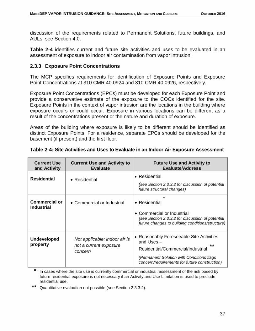
MassDEP VAPOR INTRUSION GUIDANCE: SITE ASSESSMENT, MITIGATION AND CLOSURE OCTOBER 2016
37
discussion of the requirements related to Permanent Solutions, future buildings, and AULs, see Section 4.0.
Table 2-4 identifies current and future site activities and uses to be evaluated in an assessment of exposure to indoor air contamination from vapor intrusion.
2.3.3 Exposure Point Concentrations
The MCP specifies requirements for identification of Exposure Points and Exposure Point Concentrations at 310 CMR 40.0924 and 310 CMR 40.0926, respectively.
Exposure Point Concentrations (EPCs) must be developed for each Exposure Point and provide a conservative estimate of the exposure to the COCs identified for the site. Exposure Points in the context of vapor intrusion are the locations in the building where exposure occurs or could occur. Exposure in various locations can be different as a result of the concentrations present or the nature and duration of exposure.
Areas of the building where exposure is likely to be different should be identified as distinct Exposure Points. For a residence, separate EPCs should be developed for the basement (if present) and the first floor.
Table 2-4: Site Activities and Uses to Evaluate in an Indoor Air Exposure Assessment
Current Use and Activity
Current Use and Activity to Evaluate
Future Use and Activity to Evaluate/Address
Residential Residential Residential
(see Section 2.3.3.2 for discussion of potential future structural changes)
Commercial or Industrial
Commercial or Industrial Residential *
Commercial or Industrial (see Section 2.3.3.2 for discussion of potential future changes to building conditions/structure)
Undeveloped property
Not applicable; indoor air is
not a current exposure
concern
Reasonably Foreseeable Site Activities and Uses –
Residential/Commercial/Industrial **
(Permanent Solution with Conditions flags concern/requirements for future construction)
* In cases where the site use is currently commercial or industrial, assessment of the risk posed by
future residential exposure is not necessary if an Activity and Use Limitation is used to preclude residential use.
** Quantitative evaluation not possible (see Section 2.3.3.2).
MassDEP VAPOR INTRUSION GUIDANCE: SITE ASSESSMENT, MITIGATION AND CLOSURE OCTOBER 2016
38
Pursuant to 310 CMR 40.0411(7), assessment to determine if an Immediate Response Action is required (including the presence of an IH) is an ongoing
obligation. Until the disposal site is fully assessed and a Permanent Solution is achieved, persons conducting response actions must act on new information that
indicates the potential for an Imminent Hazard.
2.3.3.1 Exposure Point Concentrations – Current Use
EPCs for current exposure are developed using the analytical results of indoor air samples, except where interior sources from ongoing commercial or industrial operations or contaminated building material confound the assessment of indoor air analytical results (i.e., it is not possible to distinguish site-related VOCs from interior sources (310 CMR 40.0926(6) and (7)).
EPCs for Imminent Hazard Evaluations (Current Use)
It is important to quickly identify if site conditions constitute an IH. Imminent Hazard evaluations should occur during the initial investigation into vapor intrusion, even if the evaluation is based upon a limited data set. If an IH is suspected, an EPC can be developed from one round of indoor air testing. In cases where the data set is limited, the maximum detected concentration should be used for the EPC. Subsequent testing may be used to update the EPCs and reevaluate the IH potential.
EPCs for No Significant Risk and No Substantial Hazard Evaluations (Current Use)
EPCs that represent a long-term exposure should be based upon multiple rounds of indoor air sampling. Consistent with 310 CMR 40.0926 and MassDEP’s Guidance for Disposal Site Risk Characterization, indoor air sample results from a given exposure point may be averaged (over time and location within the Exposure Point) provided there is sufficient data such that the average value is a “conservative estimate of the average concentration contacted by a receptor over the period of exposure.” Multiple rounds of consistent and representative data are necessary to support the use of averaging for EPCs. When data is variable or limited, a maximum or 95th upper confidence limit on the mean should be used to develop an EPC as specified in 310 CMR 40.0926(3)(c).
EPCs for Ongoing Permitted Commercial or Industrial Operations (Current Use)
In parts of buildings where VOCs are released to indoor air from permitted discharges at commercial or industrial operations, it is often difficult to evaluate vapor intrusion and develop EPCs for current receptors. In such cases, interpretation of indoor air, and in some instances sub-slab soil gas3 data, can be confounded by VOC use within the
3 In commercial buildings that use OHM, sub-slab soil gas can be contaminated through communication
with indoor air.
MassDEP VAPOR INTRUSION GUIDANCE: SITE ASSESSMENT, MITIGATION AND CLOSURE OCTOBER 2016
39
building. Examples of such situations include active dry cleaners and active petroleum dispensing operations.
The MCP provides for the use of sub-slab soil vapor data (assuming the sub-slab soil vapor is not affected by VOCs from indoor air) in these situations to estimate indoor air EPCs, as described in 310 CMR 40.0926(7)(a)1. Where it is not possible to demonstrate NSR using EPCs developed from the soil vapor data, a Permanent Solution cannot be supported. In circumstances where the presence of confounding conditions complicates the interpretation of indoor air and sub-slab data (thereby preventing completion of a meaningful risk characterization, a Temporary Solution is a possible outcome.4
Forgoing the evaluation of the vapor intrusion pathway because of confounding sources, as described above, applies only to a building, or portion of a building, where ongoing commercial, and/or industrial operations are actively using chemicals in a licensed and permitted manner that have also been identified as site COCs. EPCs must still be developed for any vapor intrusion into neighboring buildings or building units/spaces that are NOT licensed and permitted to operate such processes and do not use such chemicals (e.g., neighboring/common-wall businesses in a strip mall containing a dry cleaner).
2.3.3.2 Exposure Point Concentrations – Future Use
Current indoor air data has limited use for predicting future EPCs because buildings change over time. As buildings age or are repaired or renovated, preferential pathways can be created. Examples include:
The development of cracks in the foundation;
The introduction of annular spaces around newly installed utilities;
The installation of sub-slab lines that connect an above-ground heating oil storage tank to an oil furnace; and
The installation of an open sump.
In addition, building renovations can alter factors that change the movement of vapors between the shallow sub-slab space and indoor air, such as:
HVAC adjustments;
Change in building use that alters the frequency of doors being opened and closed; and
Construction of an addition that is located over an area of higher contamination.
4 Qualitatively, MassDEP considers the incremental exposure associated with any vapor intrusion to pose
“No Substantial Hazard” if the permitted use of the same VOCs in the building results in higher concentrations than the estimated contribution from the vapor intrusion pathway.
MassDEP VAPOR INTRUSION GUIDANCE: SITE ASSESSMENT, MITIGATION AND CLOSURE OCTOBER 2016
40
Thus, a vapor intrusion pathway of concern could develop in an existing building not currently showing evidence for vapor intrusion if soil vapor levels are sufficiently high.
EPCs for Existing Buildings (Future Use)
Current measured concentrations of VOCs in indoor air may be used as surrogates for future EPCs with consideration given to the potential for changes in building conditions that might increase vapor intrusion over time, as described below.
For buildings where the measured concentrations of VOCs in indoor air are generally consistent with (or higher than) levels expected considering measured sub-slab soil gas concentrations and empirically-based attenuation factors, the current EPCs may be used as future EPCs in the site risk characterization. This recommendation assumes that the current building conditions do not significantly impede vapor intrusion and that future building changes will not significantly increase the migration of contaminants.
For buildings where the concentration of VOCs in indoor air are significantly lower than levels that would be expected from measured sub-slab soil gas concentrations (for example, the measured sub-slab soil gas concentrations are greater than the SSGSVs with no or minimal concentrations in indoor air), the current EPCs cannot be used as future EPCs. Such circumstances indicate that the current building conditions are acting as a barrier – similar to a cap over contaminated soil – to impede (or prevent) vapor intrusion. Changes in the building may create pathways through which the VOCs in the sub-slab zone are able to migrate into the building, possibly at concentrations greater than a level of NSR.
In such cases, there are two options for future EPCs. First, future EPCs may be estimated using the current measured sub-slab soil gas concentrations in combination with empirically-based attenuation factors to calculate indoor air levels that could result from future changes in the building conditions. Given the conditions described above, such an estimate would result in future EPCs greater than the current, measured, indoor air concentrations. The estimated EPCs would then be used in the site risk characterization to determine if a level of NSR has been achieved.
Second, the current indoor air EPCs may be used as surrogates for future EPCs with the implementation of an AUL that specifies consistent/inconsistent activities and obligations/conditions to prevent the introduction (or worsening) of a vapor intrusion pathway. The AUL may allow for changes to the building, provided the potential vapor intrusion pathway is considered and it is demonstrated after the changes have been made that a level of No Significant Risk has been maintained.
MassDEP VAPOR INTRUSION GUIDANCE: SITE ASSESSMENT, MITIGATION AND CLOSURE OCTOBER 2016
41
EPCs for Future Buildings
The MCP does not allow the use of site-specific models to estimate EPCs in indoor air in buildings that have yet to be constructed (310 CMR 40.0926(7)(b)). Where concentrations exceed the GW-2 standards at a location that is currently without an existing occupied building or structure, any Permanent Solution achieved must be identified as a Permanent Solution with Conditions (310 CMR 40.1041(2)(c)2) that includes documentation of the obligation to ensure any future construction at the disposal site does not result in OHM impacts to indoor air. For more discussion of Permanent Solution with Conditions related to the potential for vapor intrusion in future buildings, see Section 4.0.
2.3.4 Exposure Assumptions
Exposure assumptions vary depending on the receptor being evaluated and the
purpose of the risk assessment.
Exposure Assumptions – Current Use
Exposure assumptions for current use are generally based on current site use and activity as described in Section 2.3.2.
Imminent Hazard Evaluations (Current Conditions)
For IH evaluations, the focus is on current site conditions (310 CMR 40.0953). Therefore, the exposure assumptions should be based on an understanding of the building as it is currently used by the receptors. The exposure period should be five years unless the COC indicates a shorter period (e.g., the OHM is more toxic acutely than sub-chronically or chronically). Exposure durations, frequencies and averaging periods used in an IH evaluation should also reflect current site conditions.
Substantial Hazard Evaluations (Current Use)
For Substantial Hazard evaluations, the focus is on current site uses (310 CMR 40.0956(1)). Therefore, the exposure assumptions should be based on an understanding of the building as it is currently used by the receptors, considering, where applicable, any Activity and Use Limitation. The exposure period is defined to be the length of time from release notification to the date of the Substantial Hazard evaluation, plus 5 years (310 CMR 40.0956(1)(b)).
No Significant Risk (Current Use)
In order to demonstrate that NSR exists or has been achieved for current residential use, the exposure assumptions used in calculating an average daily exposure should reflect continuous exposure (24 hours per day, 365 days per year, for 30 years). These assumptions conservatively address the unrestricted use of the residence, including the
MassDEP VAPOR INTRUSION GUIDANCE: SITE ASSESSMENT, MITIGATION AND CLOSURE OCTOBER 2016
42
presence of homebound individuals. (The averaging period should be 70 years for estimating cancer risks and 30 years for non-cancer risks.)
Residential exposure assumptions can also be used for buildings used for purposes other than residential in order to streamline the risk assessment process (i.e., if NSR can be demonstrated using residential exposure assumptions, then it can be assumed that NSR exists for other building uses).
For the evaluation of current exposures at a school, the assessment should address both the students (based on the actual school schedule, such as 8 hours/day, 180 days/year, and 6 years) and teachers/administrators (based on the actual school schedule, for 27 years).
In order to demonstrate NSR for commercial or industrial use, MassDEP recommends assuming 8 hours per day, 250 days per year, for 27 years. For estimating cancer risks, the averaging period for school, business, or industrial receptors should be 70 years. For estimating non-cancer risks, averaging periods should be 27 years for teachers and 6 years for students.
If more than one EPC is developed for a building, the exposure durations can be subdivided according to each location-specific EPC. For example, if an EPC for the basement and an EPC for the first floor of a residence have been determined, an exposure duration of 12 hours per day can be assumed for the basement and first floor EPCs, respectively, when calculating the average daily dose for a receptor.
Exposure Assumptions – Future Use
For unrestricted future use evaluations, exposure assumptions for residential use should be used, even if the building is not currently residential. If NSR at a site can be demonstrated using the unrestricted (residential use) exposure assumptions that include estimated future EPCs (2.3.3), exposure assumptions for other uses do not need to be evaluated. If the future use of a building must be restricted in order to demonstrate NSR or if specific future uses are ruled out and not evaluated, then an AUL must be used to eliminate such exposures from further consideration in accordance with 310 CMR 40.923(3)(b).
2.4 Risk Characterization
2.4.1 General Risk Characterization Requirements
Achieving a Permanent Solution at a site requires, in part, that NSR be demonstrated (310 CMR 40.1040(1)(a)). There are three methods of risk characterization described in the MCP. Methods 1 and 2 are designed to address risks associated predominantly with contamination of soil and groundwater. Method 3, a site-specific risk characterization, is an option at any site, but is required when significant exposure to OHM occurs through a medium other than soil or groundwater, such as indoor air.
MassDEP VAPOR INTRUSION GUIDANCE: SITE ASSESSMENT, MITIGATION AND CLOSURE OCTOBER 2016
43
A more detailed description for each risk characterization method is presented in MassDEP’s Guidance for Disposal Site Risk Characterization. Assessing risks associated with the vapor intrusion pathway presents a number of unique challenges not covered in the risk characterization guidance document, however. In this regard, vapor intrusion-specific guidance for each method is provided below.
2.4.2 Method 1 Risk Characterizations
Pursuant to 310 CMR 40.0942(1)(b)1, the use of a Method 1 Risk Characterization is restricted to disposal sites where current and reasonably foreseeable exposure would occur predominantly through contact with soil and groundwater. Method 1 is therefore not applicable if the vapor intrusion pathway has been determined to be complete and likely to be of concern in existing buildings, either currently or in the future, as described in Sections 2.2 and 2.3. Method 1 can be used, barring potential exposures to other media (surface water and sediment), if it has been concluded that a vapor intrusion evaluation is not warranted, as described in Section 1.3, or if has been determined to be incomplete or unlikely to be of concern, as described in Section 2.2 and 2.3
2.4.3 Method 2 Risk Characterizations
The limitations to Method 1 regarding contaminated media also apply to Method 2. Pursuant to 310 CMR 40.0983, a Method 2 standard can be developed for a chemical that does not have a promulgated Method 1 standard as specified at 310 CMR 40.0983(3).
Pursuant to 310 CMR 40.0926(7)(a), Method 2 also allows the use of fate and transport models in cases where direct sampling of indoor air is not possible or appropriate. In these cases, sub-slab soil gas data may be used to estimate EPCs for current use, or where appropriate, rule out an indoor air exposure pathway. Site-specific Method 2 GW-2 Standards can be developed as described at 310 CMR 40.0986. The MCP at 310 CMR 40.0986(2) requires that a Method 2 GW-2 Standard “be protective of migration of oil and/or hazardous material into indoor air.”
Method 2 Risk Characterizations based upon sub-slab soil gas data obtained under current building-specific conditions do not necessarily reflect potential future building conditions or exposures. Therefore, changes to any such building conditions would need to be “locked-in” with an appropriate AUL where there is the potential that future changes to building conditions would change the conclusion of NSR or no SH evaluation.
2.4.4 Method 3 Risk Characterizations
A Method 3 Risk Characterization is required when vapor intrusion into a building is demonstrated to be a pathway of concern, as described in Section 2.2. It would also be required if sub-slab vapors could result in a future EPC that exceeds NSR for residential use (Section 2.3).
MassDEP VAPOR INTRUSION GUIDANCE: SITE ASSESSMENT, MITIGATION AND CLOSURE OCTOBER 2016
44
Guidance for a Method 3 Exposure Assessment is presented in Section 2.3. The information collected in the Exposure Assessment, including current and future EPCs, is combined with chemical-specific toxicity to estimate cancer risks and non-cancer health effects.
Imminent Hazard risk limits are presented in 310 CMR 40.0955(2)(b) and 40.0955(2)(c);
Substantial Hazard risk limits are presented in 310 CMR 40.0956(1)(a); and
No Significant Risk limits are presented in 310 CMR 40.0993(6).
MassDEP has developed “MassDEP ShortForms for Human Health Risk Assessment under the MCP” to streamline the Method 3 risk assessment and review process. While Method 3 risk assessments are site-specific, the ShortForms provide a template for some standardized exposure scenarios, including vapor intrusion. The ShortForms spreadsheets calculate risk for standard scenarios using MassDEP recommended exposure assumptions and toxicity information. The ShortForms are available at http://www.mass.gov/eea/agencies/massdep/toxics/sources/riskasmt-htm.html#7.
MassDEP VAPOR INTRUSION GUIDANCE: SITE ASSESSMENT, MITIGATION AND CLOSURE OCTOBER 2016
45
3. MITIGATION OF THE VAPOR INTRUSION PATHWAY
This section presents guidance on considerations for remediating disposal site conditions that result in vapor intrusion, and describes a range of approaches for mitigating the vapor intrusion pathway.
Removal or treatment of contaminated soil and/or groundwater contributing to vapors in the indoor air is the most effective long-term approach for eliminating or mitigating the vapor intrusion pathway. However, the implementation of measures designed to prevent the migration of vapors into buildings is often necessary to prevent exposure for some period of time while more comprehensive response actions are being implemented.
A variety of measures to eliminate or mitigate the vapor intrusion pathway may be implemented alone or in combination and at various times during the course of response actions at the site. The selection of the appropriate approaches to eliminate or mitigate vapor intrusion should be based on consideration of the building use and receptors at the time the indoor air impact is discovered, the speed in which mitigation needs to be implemented, site conditions (building construction, depth to groundwater, source location, etc.), and the short-term and long-term remedial objectives and feasibility.
Short-term remedial objectives are typically the mitigation of indoor air levels that represent higher levels of risk, including Imminent Hazard conditions, and Critical Exposure Pathways, where feasible. Longer-term objectives include the achievement of NSR and the reduction of OHM to levels that achieve or approach background to the extent feasible in support of a Permanent Solution and site closure.
3.1 Addressing Sources of Oil and/or Hazardous Material Contamination and Migration Control
Permanent and Temporary Solutions require that all Sources of OHM Contamination be adequately identified and addressed pursuant to the Source Elimination or Control requirements at 310 CMR 40.1003(5). For a Permanent Solution, all Sources of OHM Contamination must be eliminated or if they are not eliminated, they must be eliminated to the extent feasible and controlled. Temporary Solutions require that all Sources of OHM Contamination be eliminated or controlled to the extent feasible.
Source Elimination or Control is also a requirement of Remedy Operation Status (ROS); the achievement and maintenance of ROS requires at 310 CMR 40.0893(2)(d) the elimination or control of each Source of OHM Contamination as specified at 310 CMR 40.1003(5).
Even after Sources of OHM Contamination have been successfully mitigated, the Migration Control provisions at 310 CMR 40.1003(6) require that plumes of dissolved OHM in groundwater and in vapor phase be stable or contracting. Further, MGL chapter 21E § 3A(g) requires that Permanent Solutions, where feasible, include measures to
MassDEP VAPOR INTRUSION GUIDANCE: SITE ASSESSMENT, MITIGATION AND CLOSURE OCTOBER 2016
46
“reduce to the extent possible the level of oil or hazardous materials in the environment to the level that would exist in the absence of the disposal site of concern.”
Persons conducting response actions at vapor intrusion sites should work diligently to remediate sources of VOCs in a comprehensive and timely manner so that the extent of VOC migration is minimized and the indoor air pathway is effectively mitigated for the long-term. Whenever possible, remedial actions to remove/reduce VOC sources should be expedited to reduce the need for and duration of measures necessary to mitigate a complete vapor intrusion pathway. A variety of soil and groundwater remedial approaches or combinations of approaches to remove/treat or control VOC sources may be appropriate to achieve remedial goals for the indoor air and the disposal site overall. These include: soil vapor extraction, air sparging, multi-phase extraction, in-situ chemical oxidation, bioremediation, groundwater recovery and treatment, removal and disposal of contaminated soil, soil washing, in-situ thermal treatment, permeable reactive barriers, soil solidification/stabilization, and phytoremediation. These remedial approaches can be initiated as an Immediate Response Action (IRA), a Release Abatement Measures (RAMs), or as a Comprehensive Response Actions (CRA.
Application of Remedial Additives
All remedial actions must be implemented with appropriate planning, care and oversight so that the safety and effectiveness of the remedial activities and systems. With respect to vapor intrusion sites, care must particularly be taken to ensure that any application of Remedial Additives to treat VOCs in groundwater or soil does not exacerbate site conditions and result in vapor intrusion to nearby buildings.
The MCP requires prior Departmental approval of a plan to use Remedial Additives when the proposed application is within 100 feet of a School, Daycare or Child Care Center or occupied Residential Dwelling (310 CMR 40.0046(3)(a)5). MassDEP will approve, conditionally approve or deny such plan within 30 days of its receipt. Approval of the plan may be presumed if MassDEP does not issue a written approval or denial of the plan within the 30 days; MassDEP may give oral approval of a plan in cases where the application of additives is proposed in an oral IRA Plan and written approval would delay the timely implementation of the IRA.
Specific site conditions should be considered when developing a plan for the use of Remedial Additives near occupied buildings. These conditions include, at a minimum:
the depth to groundwater;
groundwater flow direction;
soil type and hydraulic conductivity;
presence of aquitards;
presence of preferential pathways and subsurface structures;
presence of NAPL;
volume of Remedial Additives to be applied;
MassDEP VAPOR INTRUSION GUIDANCE: SITE ASSESSMENT, MITIGATION AND CLOSURE OCTOBER 2016
47
radius of influence of injections; and
distance to receptors, particularly sensitive receptors. 3.2 Response Actions to Quickly Reduce VOC Concentrations in Indoor Air Prompt action is warranted to quickly reduce or eliminate VOC concentrations in indoor air exposures from vapor intrusion when an Imminent Hazard is identified, particularly when the exposure duration of concern is very short. Section 3.2 outlines actions such as the sealing of foundation cracks/penetrations, increased ventilation, modifications to building pressurization and HVAC systems, and the use of Air Purifying Units (APUs) that can be taken almost immediately (within hours or a few days) upon identifying need for accelerated mitigation of VOCs in indoor air. 3.2.1 Sealing of Cracks, Sumps, Floor Drains and Utility Conduit Penetrations Regardless of the type of measures used to mitigate soil vapor intrusion, sealing foundation penetrations is an especially effective approach to rapidly reduce VOC concentrations in indoor air and it will enhance the effectiveness of other mitigation measures employed at the building of concern. Foundation penetrations include cracks and gaps (particularly cracks and gaps in fieldstone and block foundations), sumps, floor drains, and utility conduit penetrations. Diligence should be used in locating cracks and gaps in foundation floor slabs and walls; finished basements where walls and flooring prevent a full inspection of the foundation and slab can make this evaluation more limited and difficult. Potential entry points can be surveyed with a portable Total Organic Vapor instrument such as a photo-ionization detector (PID) or a flame ionization detector (FID), ideally that measures VOCs in the parts per billion (ppb) range. A more detailed discussion of building survey considerations is provided in Section 3.3.1. Sealants Sealing materials containing significant amounts of VOCs should be avoided. Sealant products should be specifically designed to seal concrete. Smaller cracks and gaps up to 1/8 inch in diameter may be sealed with an elastomeric sealant (e.g., caulking) or insulating foam in accordance with the manufacturer’s instructions. Cracks and gaps larger than 1/8 inch may require a foam backer rod or other comparable filler material, or filled with non-shrinking or expanding cement material (i.e. hydraulic cement). Sumps A sump in a basement can be a significant conduit for vapor intrusion and result in a direct connection between groundwater and indoor air. Sumps should be sealed with an air-tight cover with a gasket so that an air-tight seal to the slab while facilitating easy access to the pump. Appropriate fittings should be used to achieve an air-tight seal around piping and wiring. Covering and sealing the sump should be done with the knowledge that basement
MassDEP VAPOR INTRUSION GUIDANCE: SITE ASSESSMENT, MITIGATION AND CLOSURE OCTOBER 2016
48
flooding may occur in the event that water on top of the slab drains toward the sealed sump. If flooding of the basement floor is an issue, the sump cover should be level or slightly concave allowing water to flow onto it and be fitted with a one-way drain (i.e., Dranjer-type drain). This drain should be equipped with a check valve that allows water to drain into the sump but prevents soil gas from migrating into the building or conditioned air to be drawn into the sump. In addition, at buildings where a sub-slab depressurization or other active vapor intrusion mitigation system may be implemented, a check valve should be installed in the sump drain ejection piping that pumps sump water outside to prevent outside air from being drawn into the sump and potentially short-circuiting the mitigation system. Floor drains Unused floor drains should be sealed with concrete or grout and may be subject to Underground Injection Control (UIC) closure requirements administered by MassDEP’s Bureau of Water Resources and/or the local Building Department. Floor drains in commercial/industrial or school buildings can be particularly problematic because the water seal within the plumbing trap of these drains is often ineffective as the result of the water leaking out or evaporating from the trap. This condition provides a preferential pathway for soil gas to migrate into a building at the location of these drains, especially in lavatories with fans or vents and science rooms with venting hoods that create a negative pressure in the rooms. Water should be added to traps periodically to maintain the water seal or a Dranjer-type seal should be installed. Utility conduits Utility conduits penetrating the slab or foundation should be sealed with closed-cell polyurethane foam or other inert gas-impermeable material to prevent soil gas from entering the building. Utility bedding may be more permeable than the surrounding soil and serve as a preferential pathway for vapor migration into a structure. Where utility conduits are determined to be preferential pathways for vapor migration, mitigation can include venting or depressurization of the utility bedding itself if sealing the utility penetration(s) is not feasible or is ineffective. 3.2.2 Ventilation Using Windows, Doors, Vents and Fans Ventilation as a short-term vapor intrusion mitigation measure means opening windows, doors, vents or installing fans within a structure to reduce the concentration of VOCs in indoor air by mixing and diluting it with outdoor air (provided there isn’t an outside source of contaminants of concern). It is appropriate as an immediate measure (e.g., immediately following a residential fuel oil release) while remedial actions are implemented or more effective vapor intrusion mitigation is put in place. It should not be used as a long-term solution. Ventilation solely of an upper story may exacerbate the "stack effect" (advective flow of air from underneath the building as a result of a reduction in internal air pressure) and actually draw more contaminated soil gas into the structure. Balancing ventilation between the lowest level and upper stories of a structure
MassDEP VAPOR INTRUSION GUIDANCE: SITE ASSESSMENT, MITIGATION AND CLOSURE OCTOBER 2016
49
(i.e., opening a window on the ground floor when a window on a higher floor is opened) may lessen any stack effect. 3.2.3 Building Pressurization and HVAC Modification In certain situations, it is possible to modify or supplement the existing HVAC system to create positive pressure within at least the lower level of the structure to temporarily mitigate vapor intrusion. Positive pressure within the building must be consistently maintained to reduce the advective transport of soil gas into the structure. Heating and air conditioning systems may need to be modified from running on an as-needed basis to running continuously. This approach is likely to be most effective in newer construction that is relatively energy efficient; it may be less reliable and more costly in older buildings that leak air around windows, doors, and other gaps. In some buildings, manipulation of the HVAC system may be too complicated to effectively mitigate the vapor intrusion pathway. Where building pressurization is capable of reducing advective forces, diffusive flow may continue. Therefore, this approach may not be appropriate when the concentrations of contaminants in the soil gas are high. HVAC modifications may be effective in controlling vapor intrusion for some short time period, but are not suitable as a long-term mitigation measure and cannot be used to achieve a Permanent Solution. It is unreasonable to expect that running an HVAC system outside the usual range of operations will be maintained over time. Occupant activities and minor unscheduled adjustments to the HVAC system are likely to confound efforts to create positive pressure. 3.2.4 Air Purification Units
Air purification units (APUs) are portable air filtering and/or treatment devices placed within a building to improve indoor air quality. They are readily available to the general public from numerous retailers, with a wide array of treatment technologies and applications. APUs that contain activated carbon can be effective in reducing VOCs, including the chlorinated and petroleum-based contaminants common at vapor intrusion sites. When used in this manner, it is important to choose a unit with at least 10 pounds of activated carbon, with a particulate pre-filter. The inclusion of a desiccant such as Zeolites is advantageous, as water vapor can be a significant competitor for sorption sites at the low VOC concentrations of concern at many vapor intrusion sites. The APU should have a variety of fan options, with flowrates in the range of 50 to 250 CFMs. Noise levels should be at a minimum, at least for the low and mid-range flowrates, as people have a tendency to shut down these units if they are found to be too loud. Similarly, care should be taken in choosing the placement of each unit, to ensure proper setback distances (e.g., 8 to 12 inches from walls) in accordance with the manufacturer’s recommendation.
MassDEP VAPOR INTRUSION GUIDANCE: SITE ASSESSMENT, MITIGATION AND CLOSURE OCTOBER 2016
50
Experience has shown that APUs operating in an impacted space at 1 to 2 air exchanges/hour can effectively reduce concentrations of VOCs over a days-to-weeks timeframe, to concentrations less than about 20 µg/m3. It is not clear, however, if lower levels can be readily achieved at all sites. There is virtually no literature on the efficacy and effectiveness of the carbon adsorption process at very low concentrations of VOCs (e.g., less than 5 - 10 ppbV). The sorptive isotherms/capacities provided by most carbon vendors are based upon experimentation at VOC concentrations of 100 ppmV – four to five orders of magnitude higher than the low-ppbV levels of concern at vapor intrusion sites. Recent research and field observations (Fitzgerald, 2016) has suggested that there is reason to believe that the mechanisms and kinetics of sorption at low ppbV concentrations may be different than at the 100 ppmV level. As such, more frequent indoor air testing will be necessary to confirm the achievement of very low (< 5 ppbV) treatment endpoints. Similarly, it is advisable that the selection, use, and monitoring of APUs consider the possible presence of typical indoor air contaminants that are not associated with the vapor intrusion pathway, as these compounds will compete for available sorption sites, lessening the effectiveness of the carbon for the site contaminants of interest. A number of these typical contaminants, such as Toluene, Pinene, and Limonene, will be preferentially sorbed over compounds such as TCE or PCE. The presence and quantity of such “extraneous” compounds can be discerned by viewing the Total Ion Chromatograms in the TO-15 and APH test methods. While an effective initial step, APUs should only be used as a temporary mitigation measure to reduce the concentration of VOCs in indoor air prior to the implementation of a more reliable longer-term mitigation measure. The difficultly of determining the effectiveness of APUs over time, and the likelihood, owing to its portability, that an APU will be moved or turned off by building occupants, make them inappropriate for longer-term mitigation. Because sorptive mechanisms at very low VOC concentrations are not completely understood, it is difficult to determine when an APU filter will become saturated and require replacement. While it is likely that a properly operated APU containing at least 10 pounds of activated carbon will last the 6 to 12 months it should take to implement more permanent measures (assuming it can reach the desired indoor air contaminant levels), indoor air testing should be undertaken at intervening intervals in cases where sensitive receptors are present and where the Contaminant of Concern is of toxicological concern over short periods of exposure (e.g., TCE). 3.3 Indoor Air Pathway Mitigation Mitigating the vapor intrusion pathway can be accomplished by a variety of methods and implemented in stages to allow for more immediate mitigation (as outlined in Section 3.2) while longer-term approaches are developed. Once the long-term mitigation system is operational and the vapor intrusion pathway is controlled, response
MassDEP VAPOR INTRUSION GUIDANCE: SITE ASSESSMENT, MITIGATION AND CLOSURE OCTOBER 2016
51
actions to treat groundwater and/or eliminate or control sources of VOC to indoor air can be implemented or continued.
Aside from eliminating and controlling Sources of OHM Contamination at the disposal site, MassDEP considers active sub-slab depressurization (SSD) systems to be the most effective means of mitigating vapor intrusion. This view is based on MassDEP’s experience overseeing numerous vapor intrusion sites, including many state-funded projects, and its review of more than 20 years of data from radon mitigation.5 In circumstances where VOC concentrations in the soil, groundwater and/or soil gas are low, and/or site conditions preclude installation of an SSD system, a variety of other mitigation measures could be considered and may provide adequate mitigation. Regardless of the vapor intrusion pathway mitigation measure selected, the MCP requires demonstration and documentation that the performance standards for the mitigation measure are met both at the time of installation and over the course of its operation. The specifics of the performance standards depend on the objectives of the mitigation measure and must be defined in the remedial plan (i.e., IRA Plan, RAM Plan or Phase IV Remedy Implementation Plan) that describes the implementation of the mitigation measure. Consideration of this requirement is important in developing an adequate monitoring program. Monitoring requirements will vary depending on the mitigation method and the concentration of VOCs in the subsurface. More monitoring of indoor air quality is typically needed to demonstrate the effectiveness of passive measures than active systems, as passive measures are less predictable and less efficient at preventing vapor intrusion than active systems. Tables 3-1 and 3-2 contain MassDEP’s recommendations for monitoring vapor intrusion mitigation system effectiveness.
When planning the mitigation approach, several factors should be taken into consideration relative to the building structure and conditions in the subsurface near the building. These factors are discussed in more detail below.
5 Refer to http://www.epa.gov/radon/pubs/ for more information about the mitigation of radon contaminated soil gas.
The use of an active sub-slab depressurization system is MassDEP's preferred method for mitigating the vapor intrusion pathway and should be considered as the
first choice to eliminate or reduce contaminants in indoor air emanating from sub-slab soil gas.
More monitoring of indoor air quality is typically needed to demonstrate the effectiveness of passive measures than active systems, as passive measures are less
predictable and less efficient at preventing vapor intrusion than active systems.
MassDEP VAPOR INTRUSION GUIDANCE: SITE ASSESSMENT, MITIGATION AND CLOSURE OCTOBER 2016
52
3.3.1 Conducting a Building Survey
Prior to selecting the method to mitigate the vapor intrusion pathway, an inspection of the building foundation and slab should be conducted to identify all potential entry routes for VOCs in soil gas and building features that may affect the implementation of mitigation measures. As noted in Section 3.2.1, all mitigation approaches should include the step of sealing foundation penetrations that are providing a direct connection for VOCs to migrate from the subsurface to indoor air and a building inspection is necessary to identify those penetrations. Building plans, if available, can aid in performing the building survey, but a thorough inspection of the interior and exterior of the building is necessary to determine the current condition and configuration of the structure. In addition, the location of the vapor source relative to the building footprint and features should be identified so that the mitigation system can be designed properly. For some sites, such as those impacted by heating fuel oil releases, the source of vapors may be near, beneath and possibly in direct contact with the structure.
Potential soil gas entry routes include dirt floors, cracks in concrete walls or slabs, gaps in fieldstone foundation or concrete block walls, construction joints between walls and slabs, annular space around utility pipes, open sumps, etc. These potential entry points can be surveyed with a portable Total Organic Vapor instrument such as a photo-ionization detector (PID) or a flame ionization detector (FID), ideally that measures VOCs in the parts per billion (ppb) range. Although both PIDs and FIDs only display total VOCs, they are useful for screening VOCs in sub-slab soil gas inflowing through opening in the building and also have the benefit of providing continuous, real-time concentration data to evaluate trends and/or detect possible short-circuiting situations.
In addition to PIDs and FIDs, field-portable gas chromatographs (including GC/MS units) have been developed that identify and quantify specific VOCs. Some of the advantages of these instruments are that specific compounds can be identified at relatively low concentrations, the results are generated on scene (in some cases in real time) and many samples can be collected in one day. A trained technician is necessary to use this instrument successfully.
PIDs, FIDs and Field GCs are also useful to identify areas inside the building where spills may have occurred and impacted the building materials. It should be noted that PIDs and FIDs are survey/screening instruments and should not be used to conclude that vapor intrusion is not occurring or to establish Exposure Point Concentrations. Screening should always be conducted in conjunction with collecting samples for laboratory analysis using evacuated canisters to allow for comparison and confirmation of the screening results or follow-up analysis on a GC in a manner that is capable of meeting Data Quality Objectives, including the achievement of appropriate Reporting Limits.
Just as is the case with performing an assessment to determine whether vapor intrusion is occurring, items in buildings containing COCs should be identified and removed to the extent practicable prior to any sub-slab soil gas or indoor air sampling performed to design or evaluate the performance of mitigation measures. Maintaining an inventory of
MassDEP VAPOR INTRUSION GUIDANCE: SITE ASSESSMENT, MITIGATION AND CLOSURE OCTOBER 2016
53
products used in each building that can be consulted throughout the project can help to identify chemicals that may complicate the evaluation of indoor air results. For more discussion on managing and documenting potential confounding sources, see Section 2.2.4, Household Products, Commercial Products and Building Materials.
An effort should be made to identify perimeter drains or French drains, as these can be significant migration pathways and entry points for soil vapor. These drainage systems can also be an asset in vapor intrusion mitigation, as they can be connected to SSD systems to depressurize the subsurface around the foundation perimeter. Conversely, if not accounted for prior to the installation of an SSD system, these drains may short-circuit active depressurization systems. The location of footings or other sub-slab structures should also be identified, as this may impact the effectiveness of a sub-slab depressurization system by altering sub-slab vapor flow and inhibiting uniform depressurization.
Collecting differential pressure measurements as part of the building survey at multiple locations throughout the building may be useful in determining whether there are impediments to sub-slab vapor flow. In addition, this information can be used to quantify the effects of other forces such as wind, temperature, household appliances, heating or ventilation systems and occupant activities that the mitigation system will have to overcome. This information may be especially important for the design of passive sub-slab venting systems because the sub-slab differential pressures produced by passive systems are low compared to differential pressures produced by active systems. Methods for determining differential pressures are available in the USEPA (1991) Handbook, “Sub-Slab Depressurization for Low-Permeability Fill Material, Design and Installation of a Home Radon Reduction System.”
3.3.2 Permeability of Sub-Slab Materials
Understanding fill/soil conditions beneath the floor of the foundation or slab is necessary to select and design an effective mitigation system. Permeable fill/soil materials beneath the slab will usually allow rapid soil gas movement; only a slight vacuum will be necessary to create negative pressures, and fewer extraction points may be necessary when using an active depressurization system. Less permeable materials beneath the slab may require more extraction points to draw the appropriate amount of vacuum necessary to mitigate the vapor intrusion pathway.
Small diameter test holes can be drilled through the slab at various representative locations to collect sub-slab material immediately below the slab for visual inspection to assess its relative permeability. In addition, a pilot test can be conducted using the soil gas probes to evaluate the appropriate flow rates and extraction point configuration to obtain a sub-slab negative pressure in the area under the slab where the VOCs are present.
MassDEP VAPOR INTRUSION GUIDANCE: SITE ASSESSMENT, MITIGATION AND CLOSURE OCTOBER 2016
54
3.3.3 Depth to Groundwater and Surface Water Concerns
The depth to groundwater is a consideration in selecting the most appropriate vapor intrusion mitigation method. Depth to groundwater data can be obtained from monitoring wells in the vicinity of the building as well as from test holes drilled through the slab for the installation of sub-slab soil gas probes. The presence of drainage sumps is often an indication of shallow groundwater. If the seasonal high groundwater table is very shallow and close to the bottom of the foundation floor or slab, SSD systems may not be the most appropriate mitigation method.
An evaluation of the cause of the high water level beneath the slab, however, should be conducted before eliminating an SSD system as a mitigation option. Water in or around a basement is frequently the result of improper stormwater/surface water drainage. Relatively simple and inexpensive modifications to the drainage around the building (i.e., installing gutters, directing rain and surface water away from the building, etc.) can potentially reduce the infiltration of water in the basement and reduce the amount of water beneath the slab. MassDEP recommends evaluating the impact of stormwater/surface water drainage prior to eliminating an SSD system as an option due to the water level beneath the slab.
If it is determined that the water beneath the slab is shallow groundwater, measures to depress the water table (i.e., dewatering by pumping groundwater) to allow for the installation of an SSD could be evaluated as part of the overall remedial approach for the site. Measures to depress groundwater containing elevated concentrations of VOCs may require treatment (i.e., granular activated carbon) and/or a local or EPA permits to discharge the treated water to the local sewer system or surface water. Discharges to groundwater can be managed under the MCP pursuant to 310 CMR 40.0045. The costs of such treatment would be considered along with the benefits of reducing VOC concentrations and mass to facilitate site closure in an evaluation of the remedy feasibility (Phase III).
If it is determined that it is not feasible to lower the groundwater elevation through dewatering it may be possible to create a permeable zone above the basement slab to facilitate active depressurization. An aerated floor installed above an existing slab provides an open cavity through which the contaminated soil gas entering the building can be vented. See 3.5.3 for information on aerated floors.
In some instances where a significant amount of water exists close to the slab, groundwater or condensate can enter the piping of an SSD system. In such cases, consideration should be given to adding a knock-out drum before the blower. The water collected in the knock-out drum should be analyzed for VOCs to determine appropriate disposal options.
Installation of SSD systems where water is present in close proximity to the slab may require modifications to stormwater and surface water drainage in and around the
structure or dewatering beneath the slab. An evaluation of the cause of water close to the slab will be necessary to address potential drainage issues and determine the
appropriate vapor intrusion mitigation method.
MassDEP VAPOR INTRUSION GUIDANCE: SITE ASSESSMENT, MITIGATION AND CLOSURE OCTOBER 2016
55
3.3.4 Other Considerations for Mitigation Systems
All mitigation systems should be designed in conformance with standard engineering principles and practices. The installation of a mitigation system should be conducted under the direct supervision of a competent professional with demonstrated experience in the mitigation of the soil gas to indoor air pathway, disposal site remediation, or environmental engineering. As the work will likely be conducted in close proximity to building inhabitants, safety concerns are a priority. Attempts should be made to minimize noise, dust, and other nuisances/inconveniences to occupants. Alterations in the appearance of the building should also be minimized and system components should be discreetly located as practicable
3.4 Active Mitigation Systems
Vapor intrusion mitigation systems that employ a fan or blower to draw VOC vapors into collection points and discharge them away from the affected building are considered "active" mitigation systems. Summaries of various types of active mitigation systems are presented below. Active mitigation systems are considered Active Exposure Pathway Mitigation Measures or AEPMMs under the MCP (as defined at 310 CMR 40.0006(12)), measures directed at an Exposure Pathway which rely on the continual or periodic use of a mechanical or electro-mechanical device to reduce exposures and meet applicable performance standards. Information related to AEPMM remote monitoring requirements, and operating an AEPMM as part of a Temporary Solution, Remedy Operation Status or Permanent Solution, is provided in Sections 3.6.5 and 4. Recommendations for monitoring the effectiveness of active mitigation systems are provided in Table 3-1.
3.4.1 Active Sub-Slab Depressurization (SSD) Systems
Active SSD systems mitigate the vapor intrusion pathway by creating a negative pressure field (depressurization) beneath the slab of the impacted portion of the building, thereby inducing the flow of VOC vapors beneath the building to one or more collection points and subsequently discharging the vapors up a stack and into the ambient air. Appendix IV contains a detailed description of standard procedures for the installation of an SSD system.
SSD systems are based on traditional radon-mitigation technology, and consist of a fan or blower that draws soil vapor from beneath the building slab. When an existing building is retrofitted with an SSD system, extraction points are installed through the building slab. In most cases these points are installed vertically. In cases where vertical extraction points are not able to influence all areas where vapors enter through the slab, horizontal extraction points may be required. In a residential SSD system, the extraction points are typically connected to a fan installed outside of the building or in an unoccupied attic and exhausted above the top of the roof at a location so that the exhaust will not be drawn back into the building. SSD systems installed in commercial or other buildings with a large footprint to depressurize may require the use of a blower rather than a fan. Blowers should be kept within an enclosed and ideally heated area with the exhaust
MassDEP VAPOR INTRUSION GUIDANCE: SITE ASSESSMENT, MITIGATION AND CLOSURE OCTOBER 2016
56
vented outside and above the roofline. Due to the potential for some VOCs to be combustible, the need for intrinsically safe blowers, wiring and monitoring systems should be evaluated. Additionally, some VOCs may degrade membranes, piping or solvents used to fit pipes in the SSD system. Therefore, care should be taken to select materials compatible with contaminants likely to be encountered.
In new construction, the sub-slab components of the SSD system can be installed before the slab is poured to facilitate optimal system design and installation. In addition, the vertical vent pipe can be installed within the interior of the building walls.
Effective vapor intrusion mitigation using an SSD system requires a negative sub-slab pressure strong enough to overcome competing forces within the building caused by furnaces, bathroom fans, stove vents, occupant activities (i.e., opening windows and doors) or weather effects (e.g., changes in temperature, wind and barometric pressure). Therefore, pressure measurements should be evaluated under differing conditions to ensure that a negative pressure is adequate and consistently maintained.
The amount of vacuum applied to the SSD system necessary to effectively mitigate the vapor intrusion pathway may vary. In buildings with very permeable sub-slab material, large volumes of air can be moved with little pressure drop. For buildings with less permeable material beneath the slab an increased vacuum may be necessary to mitigate the pathway. Increased vacuum may also be necessary to overcome the operation of heating equipment, ventilation fans, and other competing forces described above. It should be noted, however, that excessive sub-slab depressurization can result in the back draft of combustion exhaust. Appendix IV contains more detailed information regarding back draft evaluations and related design considerations.
The presence of a sump or major utility penetration in a basement can result in significant "short-circuiting" of an SSD system and interfere with establishing a sub-slab negative pressure (i.e., vacuum) field. Sumps and utility penetrations should be sealed not only to prevent the migration of VOCs into the indoor air, but also to ensure that the SSD system operates effectively.
3.4.2 Active Drain Tile Depressurization (DTD)
Many buildings have drain tiles or French drain systems around the foundation that are designed to drain water away from the basement. These systems can be used to mitigate vapor intrusion by applying a vacuum to the system. This mitigation method is referred to Drain Tile Depressurization (DTD).
Since DTD takes advantage of existing drain tile networks located around the perimeter of the building foundation, it can be a very expeditious vapor intrusion mitigation approach to implement. These networks may be depressurized by connecting them to suction piping and a blower. Drain tiles are typically located either above or beside foundation footings, and typically consist of porous clay pipe, perforated rigid plastic pipe (i.e., PVC), or perforated flexible plastic pipe (i.e., polyethylene or polypropylene).
MassDEP VAPOR INTRUSION GUIDANCE: SITE ASSESSMENT, MITIGATION AND CLOSURE OCTOBER 2016
57
Interior drain tiles are located inside of the footings of the structure while exterior drain tiles are located outside of the foundation.
Interior drain tiles will likely provide more suction beneath the slab than exterior drain tiles. Interior drain tiles offer the advantage of being next to or below the expansion joint located near the footing and floor slab interface, which is a common soil gas entry point. It is important to determine the extent of the drain tile network, which may extend around the entire perimeter of the structure or only along a portion of the structure. DTD is most effective with a drain tile network that extends around the entire perimeter. However, effective depressurization may be possible with a drain tile network installed on one or two sides of a structure underlain by permeable soil/fill that provides good communication beneath the slab.
Sump Hole Suction
Drain tiles often drain toward a basement sump. The sump should be fitted with a removable cover with a gasket so that an air-tight seal between the cover and the slab while readily allowing easy access to the sump pump. Vent piping with a fan may be inserted through the sump cover to apply a vacuum to drain tiles and beneath the slab. Appropriate fittings should be used to achieve an air-tight seal around piping and wiring installed through the sump cover. If flooding of the basement floor is an issue, the sump cover should be level with the basement floor or slightly concave allowing water to flow onto it and be fitted with a one-way drain (i.e., Dranjer-type drain) equipped with a check valve that allows water to drain into the sump but prevents soil gas from flowing into the building. A check valve should also be installed in the sump drain ejection piping that pumps sump water to the outside to prevent outside air from being drawn into the sump which could short-circuit the DTD system.
To prevent short-circuiting of the system in buildings equipped with existing drain tiles that discharge to a dry well or topographic low point, a check valve should be installed in the discharge piping to prevent outdoor air from entering the system. A DTD system may not be the most appropriate option for addressing the vapor mitigation pathway when the basement is finished and piping needs to be inserted into the perimeter drains or when communication beneath the slab is poor. In addition, as drain tiles are often used in buildings with high water in and around the basement, there may be challenges related regarding the groundwater containing VOCs.
3.4.3 Active Block-Wall Depressurization (BWD)
Active block-wall depressurization (BWD) is a method of mitigating vapor intrusion that is occurring from soil gas migrating through void spaces in a block wall foundation. Block walls have been observed to create a stack effect, drawing soil gas through inter-connected void spaces in the blocks up into the living space of the building. SSD or DTD systems installed in buildings with block wall foundations should be designed to depressurize the zone beneath the slab and around the foundation and footings underlying the foundation to prevent soil gas migration through porous foundation walls. In cases where the SSD or DTD systems are used in building with block wall
MassDEP VAPOR INTRUSION GUIDANCE: SITE ASSESSMENT, MITIGATION AND CLOSURE OCTOBER 2016
58
foundations, the SSD or DTD system could be combined with a BWD system to enhance an SSD or DTD system.
BWD uses a vacuum to depressurize the void spaces within the foundation walls. There are generally two BWD methods. The first method consists of inserting one or two suction pipes horizontally within the void space of a foundation wall and connecting the pipes to fans to create a vacuum and depressurize the wall. The second, less common method involves drilling holes in the wall just above the slab, enclosing the holes with a perimeter baseboard, and connecting piping from the baseboard to a fan to depressurize the baseboard and wall.
It is often difficult to effectively seal the cracks and gaps in block-wall foundations, and therefore it may be difficult to depressurize the entire foundation wall. In some cases, it may be possible to use a vapor barrier over the foundation wall to limit the amount of indoor air (or outdoor air from above the ground surface) drawn into the BWD system. Excessive indoor air drawn into a BWD system (and/or SSD or DTD system) may cause back drafting of combustion equipment. See Appendix IV for information about back drafting.
3.4.4 Active Sub-Membrane Depressurization (SMD) Systems
Active sub-membrane depressurization (SMD) systems are typically used in buildings with dirt floor basements or crawlspaces. SMD systems are similar to SSD systems with the exception that depressurization occurs below an impermeable membrane instead of a concrete slab. The best approach for using an SMD system is to place various lengths of perforated piping horizontally over the dirt floor and cover the piping with a vapor barrier. To prevent the impermeable membrane from blocking the perforations in the piping when a vacuum is drawn, highly permeable material (gravel or pea stone) can be packed between and on top of the piping.
Vapor barriers used in SMD systems should be chemical resistant membranes that prevent the transmission of VOCs. Membranes should cover the entire floor area and be sealed to walls, piers, extraction piping, etc. using the appropriate procedures for the type vapor barrier being used (see Section 3.5.1 for additional information about vapor barriers). Proper sealing of the membrane to perimeter walls and piers and of membrane seams is critical for SMD systems to function effectively. Tightening the membrane too much during installation can strain seals and seams when the system is turned on and the membrane is pulled to the floor. Care should be taken so that the membrane will not be pulled away from walls and piers when the system is activated. A wearing surface is recommended above the membrane for protection. This is particularly important in areas that receive foot traffic. A vacuum sufficient to achieve a negative pressure beneath the membrane ensures that the flow of gas/air through any minor tears will be toward the depressurization system.
MassDEP VAPOR INTRUSION GUIDANCE: SITE ASSESSMENT, MITIGATION AND CLOSURE OCTOBER 2016
59
3.4.5 Off-Gas Treatment
Off-gas treatment is not required for an active mitigation system (referred to in the MCP as an Active Exposure Pathway Mitigation Measure) that is used to prevent the migration of contaminated soil gas from entering the living/working spaces of a building, provided that the system will not emit more than 100 pounds of VOCs per year (310 CMR 40.0049(3)(a)). However, MassDEP may require off-gas controls on these systems if emissions exceed, or potentially exceed significant risk level concentrations or create adverse health, safety, or odor conditions in the vicinity of the discharge. Additional guidance on off-gas treatment is provided in MassDEP Policy #WSC-94-150: Off-Gas Treatment of Point Source Remedial Air Emissions.
3.4.6 Active Pressurization Techniques
Pressurization techniques create positive pressure in or beneath the building to prevent the migration of contaminants in the sub-slab soil gas into the indoor air.
Sub-slab Pressurization
Sub-slab pressurization mitigates soil vapor intrusion by using a fan to create positive pressure below the slab that in turn creates a barrier, preventing soil gas from entering the structure. Sub-slab pressurization may be appropriate when the sub-slab material is too permeable to allow depressurization or if flows produced by the fan are too low to effectively vent beneath the slab.
Block Wall Pressurization (BWP)
Block wall pressurization (BWP) can be used to augment sub-slab pressurization in situations where the permeability of the sub-slab material is too high to effectively depressurize. It can also be used as an alternative to block wall depressurization when depressurization has resulted in back drafting of combustion appliances. BWP may be particularly helpful when a block wall is identified as a soil gas entry route/preferential pathway. In this configuration, piping is typically inserted into the base of the block wall at one or more locations so that air blows into the wall and sub-slab environment creating a flow away from the block wall and slab.
3.5 Passive Measures
Passive mitigation measures include the installation of a barrier or barriers to prevent the migration of contaminated vapors to the indoor air, or a venting system to create a preferential pathway to divert the vapors from the subsurface to the ambient air above the building. These measures are considered "passive" because they do not employ a fan or blower or other electro-mechanical device as a component of the mitigation system. Passive mitigation measures are considered Passive Exposure Pathway Mitigation Measures under the MCP (as defined at 310 CMR 40.0006(12)). Recommendations for monitoring the effective of passive mitigation systems are provided in Table 3-2.
MassDEP VAPOR INTRUSION GUIDANCE: SITE ASSESSMENT, MITIGATION AND CLOSURE OCTOBER 2016
60
3.5.1 Vapor Barriers
Vapor barriers installed for the purpose of preventing VOC-contaminated soil gas from entering a building should not be confused with vapor barriers used in conventional building construction to prevent the intrusion of water vapor.
Vapor barriers intended to address VOCs should be installed above a permeable layer that allows soil vapors to migrate freely to the perimeter of the building or up and out through passive or active vent piping. Vapor barriers may be composed of high density polyethylene (HDPE), low density polyethylene (LDPE), very-low density polyethylene (VDPE) materials; spray-applied materials composed of a rubberized asphalt emulsion or epoxy (USEPA, 2008); or any other chemical resistant membrane that prevents the transmission of VOCs.
While there are currently no standards for the thickness, composition, or physical properties of a membrane system that will ensure its effectiveness, it is recommended that membranes be at least 40 to 60 mil thick (USEPA, 2008), be composed of materials that are compatible with chemicals known or likely to be present at the disposal site, and be demonstrated to not significantly absorb VOCs. Using a membrane with a thickness of 60 to 100 mil may help reduce the potential for punctures during construction activities (e.g., cutting or grinding of rebar just above the barrier, installation of stakes for concrete forms, dropping tools, foot traffic, etc.) or from the installation of the slab after the membrane is in place (ITRC, 2007). Ultimately, the vapor barrier should have a thickness and composition adequate to prevent vapor intrusion and withstand damage during construction. Although it is possible to install a vapor barrier as a retrofit to an existing building, these systems are generally better suited to new construction, where the appropriate amount and type of sub-slab bedding material can be specified and verified, and the proper installation of membrane barriers can be assured.
Vapor barriers should undergo a comprehensive quality assurance/quality control (QA/QC) process as part of the installation procedure to ensure soil gas entry routes have been eliminated. Manufacturers of membrane systems typically have stringent QA/QC standards and testing requirements. These requirements include ensuring manufacturer- recommended overlap at seams, complete welds connecting sheet materials, and effective sealing of utility penetrations through the membrane. Smoke testing is one method of testing membrane integrity. It consists of pumping smoke beneath the membrane, checking for smoke penetrating the membrane, and patching areas of observed smoke penetration.
The installation of the vapor barrier should be performed by a trained, experienced, and certified installer. Some manufacturers provide installer certification, or offer third party inspection services and warranties. It is recommended that an environmental professional observe the installation of the slab above the vapor barrier to ensure that the concrete contractors do not penetrate the vapor barrier.
MassDEP VAPOR INTRUSION GUIDANCE: SITE ASSESSMENT, MITIGATION AND CLOSURE OCTOBER 2016
61
Multiple rounds of indoor air sampling are recommended after the floor is completed to demonstrate that the vapor barrier is effective (see Tables 3-1 and 3-2).
3.5.2 Passive Venting
Passive venting mitigates the vapor intrusion pathway by intercepting sub-slab soil gas with a series of perforated pipes (typically 4-in. diameter), installed below the slab within a permeable bedding material, such as sand or gravel. The perforated piping is typically connected to solid piping and vented to the atmosphere above the roof line. Where possible, a vapor barrier such as described in Section 3.5.1, should be used in conjunction with a passive venting system.
A passive venting system relies on temperature and pressure differences, and wind speed to induce soil gas flow and removal. As a result, to ensure its effectiveness, the system must include sufficient interception piping and highly permeable bedding, and the barrier system must be properly installed. Passive venting systems should be designed so that a fan can be easily added to transform the system to an active SSD system if a greater reduction in the concentrations of VOCs is necessary to achieve mitigation goals.
Pre-fabricated floor systems that create a continuous aerated space beneath the slab or raised aerated floor above an existing slab are a form of passive venting system that eliminates the need for passive vent piping and permeable bedding material. Aerated floor systems may also, when fitted with a fan or blower, be converted to an active SSD system. See 3.5.3 for additional information on Aerated Floor Systems.
As with a vapor barrier, passive venting systems are more easily installed in and generally better suited to new construction, where the appropriate amount and type of sub-slab bedding material can be specified and verified and proper installation can be assured.
Some passive venting systems incorporate the use a wind-driven turbine on the top of the vent pipe to enhance flow within the passive system. If the wind-driven turbine is determined to be necessary to maintain NSR, then the system would be considered an active mitigation system and this would have implications for MCP closure as discussed in Section 4.6. Wind-driven turbines should be used with caution. Turbines will not induce the flow of sub-slab soil gas if the wind is not blowing, and may actually inhibit the flow of soil gas to the atmosphere when ice or snow accumulates on or within the turbine.
EPA, ITRC and other sources suggest that passive systems may not reliably mitigate soil vapor intrusion during a variety of weather conditions, occupant activities, and/or appliance usage. For example:
EPA states, “Passive soil depressurization techniques will always be less effective than active soil depressurization. The effectiveness of passive soil depressurization techniques in existing houses is unpredictable, highly variable,
MassDEP VAPOR INTRUSION GUIDANCE: SITE ASSESSMENT, MITIGATION AND CLOSURE OCTOBER 2016
62
and often modest, at best. Passive systems will likely find their greatest application in new construction, where features can be incorporated into the house during construction to help improve passive performance" (USEPA,1993, p.3).
ITRC describes passive venting systems as “not as effective as active venting [sub-slab depressurization]; ambient temperatures and winds can adversely impact success; not suitable for existing structures unless very modest concentration reductions are required; upgrade to active venting [sub-slab depressurization] likely to be necessary for new structures when large reductions in concentrations (e.g., greater than ~90%) are required.”(ITRC, 2007, Table 4-3, p. 47).
Because passive venting systems are not generally as reliably effective as active SSD systems, MassDEP does not consider their use appropriate to mitigate Imminent Hazards. Passive venting may be appropriate to mitigate the vapor intrusion pathway in some cases, particularly when high reductions in soil gas concentrations are not needed. Passive mitigation measures - passive venting systems and vapor barriers - typically require more monitoring of indoor air quality to demonstrate the effectiveness than active mitigation systems to ensure their consistent effectiveness over a range of weather and other conditions that can affect their performance. Reliance on a passive venting system requires sufficient indoor air sampling to demonstrate that the venting is mitigating the vapor intrusion pathway and that indoor air concentrations are consistently reduced to the extent necessary to meet mitigation requirements. See Section 3.6 for more discussion about demonstrating the effectiveness of a mitigation system.
3.5.3 Aerated Floor Systems
Aerated floor systems typically consist of plastic, prefabricated, interlocking forms placed upon a compacted sub-base material (i.e., gravel) with rebar and concrete installed and poured above the forms. The forms create a ventilated void space beneath the interlocking forms and concrete that may include air inlets installed in a traditional foundation wall on one side of a building to allow air in while interior vertical vent piping installed on the opposite side allows sub-slab air to be discharged above the roof. Aerated floor systems can be used in new construction or in modifications to an existing building and are available in a variety of sizes depending on the sub-slab void space required. Therefore, aerated floor systems may provide passive ventilation by creating a continuous ventilated space beneath the slab that allows discharge to the atmosphere. If greater reductions of contaminants in sub-slab soil gas or indoor air are required, a fan or blower can be used to actively depressurize or ventilate the sub-slab void space. Water or condensation that may occur within the void space beneath the slab is able to drain outside through openings in the foundation wall. Following installation and pouring of concrete above the forms, the system should be checked to identify air leaks and determine if a fan or blower is necessary.
MassDEP VAPOR INTRUSION GUIDANCE: SITE ASSESSMENT, MITIGATION AND CLOSURE OCTOBER 2016
63
3.6 Demonstration of Mitigation Effectiveness, Maintenance and Monitoring
As with any mitigation or remedial action conducted under the MCP, post-installation verification of system performance and demonstration of continued effectiveness are required. Regardless of the mitigation approach selected, indoor air sampling should be conducted after implementation to demonstrate that the approach was effective. The appropriate method, frequency and timing for demonstrating continued effectiveness will depend on the mitigation approach.
Recommended sampling and monitoring regimens for both active and passive mitigation measures are outlined in Tables 3-1 and 3-2 and discussed in this section.
3.6.1 Performance Standards
The remedial objectives and specific performance objectives for remedial measures, including mitigation systems, should be specified in the relevant plan (e.g. IRA Plan, RAM Plan, Remedy Implementation Plan). Short-term remedial objectives include eliminating IHs, and mitigating CEPs, where feasible. Longer-term remedial objectives include the achievement of NSR and the reduction of OHM to levels that achieve or approach background to the extent feasible in support of a Permanent Solution and site closure.
The specific approach for demonstrating that performance standards have been and continue to be met should also be presented in the plan, and will vary depending on the type of mitigation measure employed. MassDEP’s recommendations for such demonstrations are described below.
3.6.2 Demonstration of Effectiveness for Active Mitigation Systems
As discussed in Section 3.4, there are a variety of active vapor intrusion mitigation systems that can be implemented. This section focuses on SSD systems, as they provide an effective, reliable and consistent means of addressing vapor intrusion and are most commonly use.
The effectiveness of an active depressurization system can be demonstrated by sampling indoor air in conjunction with confirmation of a negative pressure field beneath the slab as described in Sections 3.6.2.2. Once the effectiveness has been demonstrated, future monitoring may be limited to measuring the negative pressure field beneath the slab and where warranted, additional indoor air sampling, as described in Section 3.6.2.3.
3.6.2.1 Indoor Air Quality Monitoring - Active Mitigation Systems
The creation of an effective sub-slab negative pressure field should result in the reduction of VOC concentrations in the indoor air within the building. After SSD system startup, indoor air quality samples should be collected to confirm that concentrations of VOCs in indoor air are reduced to the extent needed to meet the remedial objective specified in the relevant plan. Generally this sampling should be done approximately 7 days after system
MassDEP VAPOR INTRUSION GUIDANCE: SITE ASSESSMENT, MITIGATION AND CLOSURE OCTOBER 2016
64
startup. In the case of an Imminent Hazard, sampling can be conducted as soon as 24 hours after startup.
If the indoor air sampling indicates that the system as installed is not meeting specified remedial objectives, the system should be augmented, modified, or another approach selected that will achieve the goals of the response actions. These additional measures and re-sampling to determine effectiveness should be implemented as soon as possible. Once the system is operating as specified, effectiveness monitoring should be conducted (see recommendations provided in Table 3-1).
Subsequent to this initial evaluation, additional indoor air sampling event during the winter heating season is necessary (unless the initial evaluation is conducted during winter months) if non-winter SSD negative pressure conditions or initial indoor air sampling results were marginal. December through March is considered the winter heating season.
If, despite system modifications, indoor air quality data continues to indicate elevated concentrations of VOCs, further evaluation of indoor air data and other Lines of Evidence should be conducted. Building conditions, SSD system parameters, sub-slab pressure readings, and soil gas data should be reviewed to determine whether the indoor air sampling is detecting contaminants from indoor/non-site sources, the SSD system requires additional modification or expansion in the form of additional soil vapor extraction points, or a preferential pathway exists. "Short-circuiting" problems are of particular concern, where cracks, holes, sumps, or annulus spaces in the building foundation/slab disrupt a negative pressure field.
Once SSD system effectiveness has been demonstrated through concurrent indoor air sampling and collection of sub-slab pressure measurements, indoor air quality should continue to be acceptable as long as the negative pressure is maintained at the soil vapor monitoring locations across the slab. Pressure field measurements can be used to monitor the system following the initial evaluation. If negative pressures across the entire slab are not maintained, the reason should be investigated and the system modified, as necessary. The indoor air should be re-sampled once the system is modified to demonstrate that the modifications are adequate to prevent vapor intrusion. Although reading the magnahelic (differential pressure) gauge from the extraction point(s) may be considered an indicator of sub-slab negative pressure, vacuum applied from the extraction point(s) may not translate into adequate negative pressure beneath the entire slab if, for example, short-circuiting occurs. Therefore, direct measurement of the negative pressure across the slab is recommended.
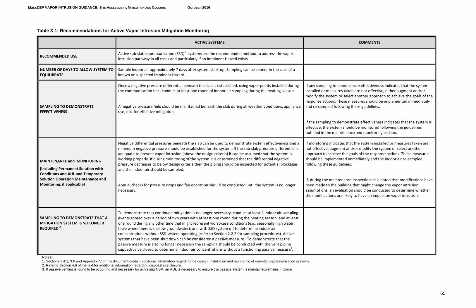
MassDEP VAPOR INTRUSION GUIDANCE: SITE ASSESSMENT, MITIGATION AND CLOSURE OCTOBER 2016
65
Table 3-1: Recommendations for Active Vapor Intrusion Mitigation Monitoring
ACTIVE SYSTEMS COMMENTS
RECOMMENDED USE Active sub-slab depressurization (SSD)1 systems are the recommended method to address the vapor intrusion pathway in all cases and particularly if an Imminent Hazard exists
NUMBER OF DAYS TO ALLOW SYSTEM TO EQUILIBRATE
Sample indoor air approximately 7 days after system start-up. Sampling can be sooner in the case of a known or suspected Imminent Hazard.
SAMPLING TO DEMONSTRATE EFFECTIVENESS
Once a negative pressure differential beneath the slab is established, using vapor points installed during the communication test, conduct at least one round of indoor air sampling during the heating season.
A negative pressure field should be maintained beneath the slab during all weather conditions, appliance use, etc. for effective mitigation.
If any sampling to demonstrate effectiveness indicates that the system installed or measures taken are not effective, either augment and/or modify the system or select another approach to achieve the goals of the response actions. These measures should be implemented immediately and re-sampled following these guidelines.
If the sampling to demonstrate effectiveness indicates that the system is effective, the system should be monitored following the guidelines outlined in the maintenance and monitoring section.
MAINTENANCE and MONITORING
(Including Permanent Solution with Conditions and AUL and Temporary Solution Operation Maintenance and Monitoring, if applicable)
Negative differential pressures beneath the slab can be used to demonstrate system effectiveness and a minimum negative pressure should be established for the system. If the sub-slab pressure differential is adequate to prevent vapor intrusion (above the design criteria) it can be assumed that the system is working properly. If during monitoring of the system it is determined that the differential negative pressure decreases to below design criteria then the piping should be inspected for potential blockages and the indoor air should be sampled.
Annual checks for pressure drops and fan operation should be conducted until the system is no longer necessary.
If monitoring indicates that the system installed or measures taken are not effective, augment and/or modify the system or select another approach to achieve the goals of the response actions. These measures should be implemented immediately and the indoor air re-sampled following these guidelines.
If, during the maintenance inspections it is noted that modifications have been made to the building that might change the vapor intrusion assumptions, an evaluation should be conducted to determine whether the modifications are likely to have an impact on vapor intrusion.
SAMPLING TO DEMONSTRATE THAT A MITIGATION SYSTEM IS NO LONGER REQUIRED 2
To demonstrate that continued mitigation is no longer necessary, conduct at least 3 indoor air sampling events spread over a period of two years with at least one round during the heating season, and at least one round during any other time that might represent worst-case conditions (e.g., seasonally high water table where there is shallow groundwater); and with SSD system off to determine indoor air concentrations without SSD system operating (refer to Section 2.2.2 for sampling procedures). Active systems that have been shut down can be considered a passive measure. To demonstrate that the passive measure is also no longer necessary the sampling should be conducted with the vent piping capped/valve closed to determine indoor air concentrations without a functioning passive measure3.
Notes: 1. Sections 3.4.1, 3.6 and Appendix IV of this document contain additional information regarding the design, installation and monitoring of sub-slab depressurization systems. 2. Refer to Section 4.6 of the text for additional information regarding disposal site closure. 3. If passive venting is found to be occurring and necessary for achieving NSR, an AUL is necessary to ensure the passive system is maintained/remains in place.
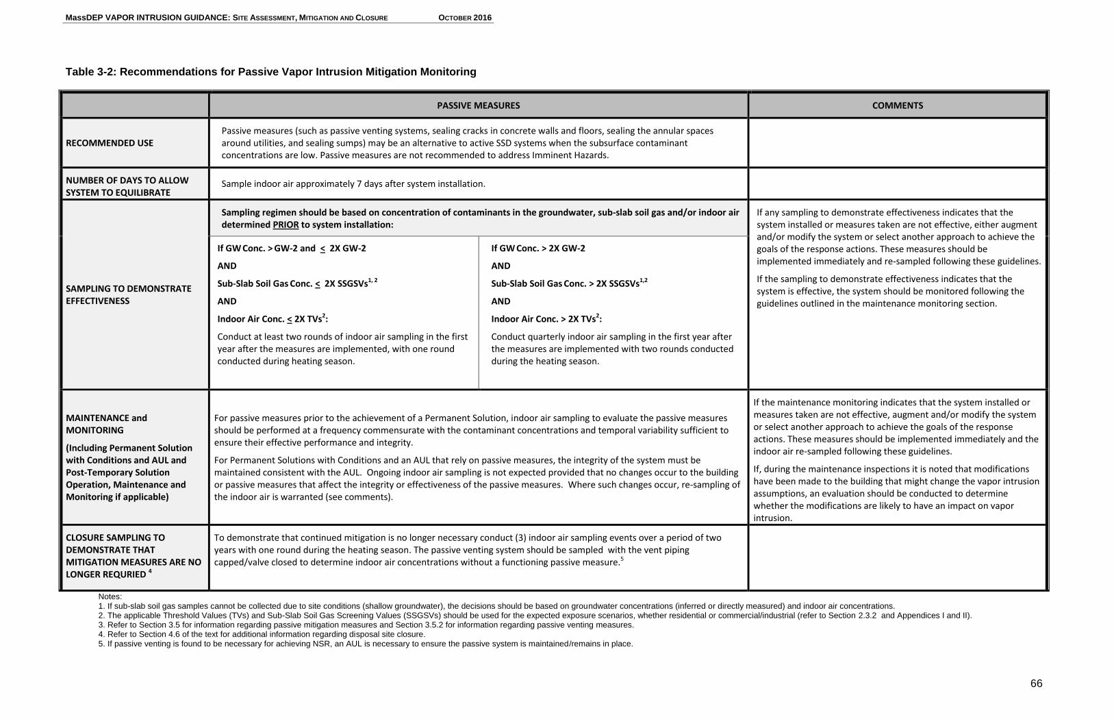
MassDEP VAPOR INTRUSION GUIDANCE: SITE ASSESSMENT, MITIGATION AND CLOSURE OCTOBER 2016
66
Table 3-2: Recommendations for Passive Vapor Intrusion Mitigation Monitoring
Notes: 1. If sub-slab soil gas samples cannot be collected due to site conditions (shallow groundwater), the decisions should be based on groundwater concentrations (inferred or directly measured) and indoor air concentrations. 2. The applicable Threshold Values (TVs) and Sub-Slab Soil Gas Screening Values (SSGSVs) should be used for the expected exposure scenarios, whether residential or commercial/industrial (refer to Section 2.3.2 and Appendices I and II). 3. Refer to Section 3.5 for information regarding passive mitigation measures and Section 3.5.2 for information regarding passive venting measures. 4. Refer to Section 4.6 of the text for additional information regarding disposal site closure. 5. If passive venting is found to be necessary for achieving NSR, an AUL is necessary to ensure the passive system is maintained/remains in place.
PASSIVE MEASURES COMMENTS
RECOMMENDED USE Passive measures (such as passive venting systems, sealing cracks in concrete walls and floors, sealing the annular spaces around utilities, and sealing sumps) may be an alternative to active SSD systems when the subsurface contaminant concentrations are low. Passive measures are not recommended to address Imminent Hazards.
NUMBER OF DAYS TO ALLOW SYSTEM TO EQUILIBRATE
Sample indoor air approximately 7 days after system installation.
SAMPLING TO DEMONSTRATE EFFECTIVENESS
Sampling regimen should be based on concentration of contaminants in the groundwater, sub-slab soil gas and/or indoor air determined PRIOR to system installation:
If any sampling to demonstrate effectiveness indicates that the system installed or measures taken are not effective, either augment and/or modify the system or select another approach to achieve the goals of the response actions. These measures should be implemented immediately and re-sampled following these guidelines.
If the sampling to demonstrate effectiveness indicates that the system is effective, the system should be monitored following the guidelines outlined in the maintenance monitoring section.
If GW Conc. > GW-2 and < 2X GW-2
AND
Sub-Slab Soil Gas Conc. < 2X SSGSVs1, 2
AND
Indoor Air Conc. < 2X TVs2:
Conduct at least two rounds of indoor air sampling in the first year after the measures are implemented, with one round conducted during heating season.
If GW Conc. > 2X GW-2
AND
Sub-Slab Soil Gas Conc. > 2X SSGSVs1,2
AND
Indoor Air Conc. > 2X TVs2:
Conduct quarterly indoor air sampling in the first year after the measures are implemented with two rounds conducted during the heating season.
MAINTENANCE and MONITORING
(Including Permanent Solution with Conditions and AUL and Post-Temporary Solution Operation, Maintenance and Monitoring if applicable)
For passive measures prior to the achievement of a Permanent Solution, indoor air sampling to evaluate the passive measures should be performed at a frequency commensurate with the contaminant concentrations and temporal variability sufficient to ensure their effective performance and integrity.
For Permanent Solutions with Conditions and an AUL that rely on passive measures, the integrity of the system must be maintained consistent with the AUL. Ongoing indoor air sampling is not expected provided that no changes occur to the building or passive measures that affect the integrity or effectiveness of the passive measures. Where such changes occur, re-sampling of the indoor air is warranted (see comments).
If the maintenance monitoring indicates that the system installed or measures taken are not effective, augment and/or modify the system or select another approach to achieve the goals of the response actions. These measures should be implemented immediately and the indoor air re-sampled following these guidelines.
If, during the maintenance inspections it is noted that modifications have been made to the building that might change the vapor intrusion assumptions, an evaluation should be conducted to determine whether the modifications are likely to have an impact on vapor intrusion.
CLOSURE SAMPLING TO DEMONSTRATE THAT MITIGATION MEASURES ARE NO LONGER REQURIED 4
To demonstrate that continued mitigation is no longer necessary conduct (3) indoor air sampling events over a period of two years with one round during the heating season. The passive venting system should be sampled with the vent piping capped/valve closed to determine indoor air concentrations without a functioning passive measure.5
MassDEP VAPOR INTRUSION GUIDANCE: SITE ASSESSMENT, MITIGATION AND CLOSURE OCTOBER 2016
67
3.6.2.2 Confirmation of Negative Pressure Field - Active Mitigation Systems
The ongoing effectiveness of the SSD system can be demonstrated by confirming that a negative pressure field extends under the slab where VOCs are present. Pressure testing at representative "worst case" soil vapor monitoring locations after system startup should provide sufficient information to demonstrate the presence of a negative pressure field. Measurement of differential pressure is the most direct indicator of vapor extraction and should be checked periodically. After the pressure field is confirmed following system start-up, and the system is shown to be consistently effective, monitoring of an in-line manometer (pressure gauge) or other pressure gauge is generally an adequate indicator of satisfactory system operation. Appendix IV of this document contains additional information regarding the confirmation of the pressure field of an active mitigation system.
As stated in Section 3.3.2, in buildings with very permeable sub-slab material, large volumes of air can be moved with little pressure drop. For other buildings with less pervious material beneath the slab, additional sub-slab depressurization through higher flow rates may be necessary to overcome ambient fluctuations in building pressures caused by HVAC systems, vents, fans and appliances. It is possible for taller buildings to exhibit greater stack effects due to wind effects on higher floors. Therefore, some structures may require additional sub-slab negative pressure to overcome building-specific effects.
3.6.2.3 Maintenance and Monitoring of Active Mitigation Systems
The primary performance criterion for SSD systems during maintenance and monitoring stage of operation is ensuring that the differential pressure observed across the slab during system start up is being maintained. Monitoring the differential pressure may be accomplished by reading the manometer value at the primary extraction point(s), and ideally collecting differential pressure measurements at soil vapor monitoring points across the slab, using a magnehelic gauge or digital micromanometer with a range suitable for the vacuum encountered. The differential pressure should be checked to verify that the value is adequate to prevent vapor intrusion (i.e., not varying significantly from the initial differential pressure value observed at the time the indoor air concentrations were initially demonstrated to be acceptable). If the differential pressure is not adequate to prevent vapor intrusion based on the original testing, the indoor air should be sampled to determine whether the observed differential pressure is effectively reducing indoor air concentrations. Annual checks for pressure drops and fan operation should be conducted while the system is in operation.
Maintenance of the SSD system should be performed as necessary. Monitoring should include a visual inspection of system piping to identify cracks and gaps at joints. Condensate bypass and interior drain lines should be inspected with valves in the open position. Mitigation system monitors and alarms, including remote monitoring/telemetry and carbon monoxide alarms, should be tested during each site visit if they are present. Fans and blowers should be observed for excessive noise, visually inspected to look for
MassDEP VAPOR INTRUSION GUIDANCE: SITE ASSESSMENT, MITIGATION AND CLOSURE OCTOBER 2016
68
vibration, moisture, or corrosion, and the cut-off switch determined to be operable. A mitigation system Completion Report with an as-built drawing of the system can be helpful during routine inspections to identify changes to the system. An example of a Sub-Slab Depressurization System Completion Report used by MassDEP is provided in Appendix IV.
The condition of basement walls, floors and utility penetrations should be evaluated during each inspection to identify cracks and gaps and inspect the condition of previous sealing. The location and size of cracks should be documented. As discussed previously (Section 3.2.1), sump covers should be inspected to ensure the seal for the sump is not compromised and there are no openings through which soil vapor may enter. Floor drains should be equipped with a seal that has no cracks or gaps that would allow soil vapor to enter. Any modifications to the building should be noted and an evaluation conducted to determine whether the modifications have had an impact on vapor intrusion.
If any observations are made during the inspections that indicate that the system installed or measures taken are not effective (e.g., new openings in the foundation/slab, broken or blocked piping, etc.), the necessary repairs should be made immediately and the indoor air should be sampled to confirm the effectiveness of repairs.
3.6.3 Demonstration of Effectiveness of Passive Mitigation Measures
The demonstration of effectiveness and monitoring of passive mitigation measures used to address vapor intrusion require sampling indoor air. More indoor air sampling is typically necessary to demonstrate the effectiveness of passive mitigation measures than active mitigation systems since passive measures are less predictable and efficient at reducing or preventing vapor intrusion.
3.6.3.1 Indoor Air Quality Monitoring - Passive Mitigation Measures
After implementation of passive measures, indoor air quality samples should be collected to confirm that concentrations of VOCs in indoor air are reduced to the extent specified in the relevant plan. Generally, this confirmatory monitoring should be done approximately 7 days after the measures are completed.
The recommended sampling approach to demonstrate effectiveness of passive measures depends on the relative groundwater and sub-slab soil gas concentrations, as well as the indoor air concentrations prior to the completion of the passive mitigation measures. More extensive testing is recommended when subsurface and indoor air concentrations are higher. Recommendations for sampling to demonstrate the effectiveness of passive measures are provided in Table 3-2 and discussed below:
If the concentrations of VOCs in the vicinity of the building prior to implementing the passive measures are relatively low (groundwater concentrations are equal to or less than 2 times the GW-2 Standards and the sub-slab soil gas
concentrations in are equal to or less than 2 times the applicable SSGSVs in
MassDEP VAPOR INTRUSION GUIDANCE: SITE ASSESSMENT, MITIGATION AND CLOSURE OCTOBER 2016
69
Appendix 2); and the indoor air concentrations are equal to or less than two times the appropriate Threshold Values), then indoor air sampling at least twice in the first year is recommended, with one round conducted during the heating season.
If the concentrations of VOCs in the vicinity of the building prior to implementing the passive measures are relatively high (groundwater concentration is greater than 2 times the GW-2 Standards, and/or the sub-slab soil gas concentrations are greater than 2 times the applicable SSGSVs in Appendix 2; and/or the indoor air concentrations are greater than two-times the appropriate Threshold Values), then quarterly indoor air sampling within the first year is recommended, with two rounds conducted during the heating season.
If sampling indicates that the measures as installed are not effective, the mitigation approach or system should be augmented, modified or another approach selected that will achieve the goals of the response actions. In cases where a passive venting system is not effective, the system should be made active by the installation of a fan or blower. These additional measures and re-sampling to determine effectiveness should be implemented as soon as possible. In the event that passive system is made active, the effectiveness and monitoring of the system should follow the guidelines for active systems outlined in Section 3.6.2 and Table 3-1. 3.6.3.2 Maintenance and Monitoring of Passive Mitigation Measures If the passive measures are determined to be effective based on the initial sampling, on-going monitoring should consist of additional indoor air sampling conducted at a frequency commensurate with the contaminant concentrations and observed temporal variability that is sufficient to ensure the measure's effective performance over time and across a range of conditions. For Permanent Solutions that rely on passive mitigation measures, indoor air sampling after the achievement of a Permanent Solution is not expected provided that no changes occur to the building or measures that affect the integrity or effectiveness of the passive mitigation measures. Such measures must be maintained in accordance with the AUL to ensure NSR. Where changes that may affect the passive mitigation measure occur, re-sampling of the indoor air is warranted (as discussed below). Monitoring recommendations for passive measures are provided in Table 3-2. The monitoring program should be specified in the relevant response action plan. Routine inspections should be conducted as appropriate to ensure continued effectiveness and/or as required by the MCP. The nature of these inspections will depend on the specific measures implemented. For example, for a passive venting system, inspections should include a visual check of system piping to identify cracks and gaps at joints. The as-built drawing for the system should be examined to ensure the system configuration has not been modified. The condition of basement walls, floors and utility penetrations should be evaluated during each inspection to identify cracks and gaps and inspect the condition of
MassDEP VAPOR INTRUSION GUIDANCE: SITE ASSESSMENT, MITIGATION AND CLOSURE OCTOBER 2016
70
previous sealing. The location and size of cracks should be documented. As discussed previously (Section 3.2.1), sump covers should be inspected to ensure the seal for the sump is not compromised and there are no openings through which soil vapor may enter. Floor drains should be equipped with a seal that has no cracks or gaps that would allow soil vapor to enter. Any modifications to the building should be noted and an evaluation should be conducted to determine whether the modifications are likely to have an impact on vapor intrusion. If any observations are made during the inspections that indicate that the measures implemented may no longer be effective (e.g., identification of new penetrations in the foundation/slab, broken or blocked piping, etc.), the necessary repairs should be made immediately and the indoor air should be sampled to confirm the effectiveness of the repairs. If it is determined that the passive measures are no longer effective, either through sampling or observation, the measures should be augmented or modified, or another approach selected that will achieve the response action goal. In cases where a passive venting system was installed, the system should be made active by the installation of a fan or blower when sampling indicates the system is not effective. 3.6.4 Monitoring Reports
Information collected during the inspections of active and passive mitigation systems and measures should be included in the appropriate Status Report or Remedial Monitoring Report, as required by the MCP. This information includes, but is not limited to: pressure test data and flow rate readings, laboratory and screening results from analyses of indoor air and/or discharged vapor samples (if conducted), observations of the condition of and the result of tests performed on the system components, any problems identified, and any changes made to the mitigation system/measures. MassDEP recommends keeping inspection information in a logbook located onsite.
3.6.5 Telemetry on Active Mitigation Systems
The MCP requires the use of telemetry or remote monitoring as part of Active Exposure Pathway Mitigation Measures (i.e., active mitigation measures) implemented to support a Permanent Solution with Conditions, a Temporary Solution or Remedy Operation Status. Section 4 provides discussion of the regulatory requirements applicable to operating Active Exposure Pathway Mitigation Measures as part of maintaining site closure and these milestones in the response action process.
Telemetry is required to "alert the owner and operator of the building that is protected by the Active Exposure Pathway Mitigation Measure and the Department immediately upon failure of the system, such as loss of power, mechanical failure or other significant disruption of the effectiveness of the system."
To meet the MCP requirement that the telemetry system is able to communicate immediately with Department upon system failure, the system must be registered with MassDEP. The registration process includes a test to confirm that the telemetry system is able to able to communicate to MassDEP when the AEPMM shut offs and when it
MassDEP VAPOR INTRUSION GUIDANCE: SITE ASSESSMENT, MITIGATION AND CLOSURE OCTOBER 2016
71
restarts. The registration process is considered complete once MassDEP confirms that the communication test was successful.
Registration instructions titled “Remote Telemetry Information for Active Exposure Pathway Mitigation Measures” may be found on MassDEP’s website at http://www.mass.gov/eea/agencies/massdep/cleanup/regulations/remote-telemetry-information.html.
3.7 Closure Sampling to Demonstrate that a Mitigation System is No Longer Required
To demonstrate that an active or passive system is no longer required to mitigate the vapor intrusion pathway, MassDEP recommends a minimum of three rounds of indoor air sampling collected over two years, with at least one round collected during the heating season (generally presumed worst-case condition), and one during any other time that might represent worst-case conditions (e.g., seasonally high water table where groundwater is shallow). Recommendations for closure sampling are summarized in Tables 3-1 and 3-2.
In the case of an active mitigation system that is in operation, the system should be shut off and the vent pipe should be capped or the valve to the vent piping closed prior to and during these sampling events to assess whether the system is still needed. MassDEP recommends the system be turned off for at least seven days prior to sampling to allow for equilibration. Once the indoor air samples have been collected, the system should be turned back on until the next sampling event. If it can be demonstrated that remedial objectives have been achieved without the system operating during each of the three sampling events, the system can be shut down.
In the case of sampling to demonstrate that a passive venting system is no longer required, including the passive system that remains in place when an active system is shut down, the passive venting system vent pipe should be capped or the valve in the vent piping closed during each of the indoor air sampling events to effectively prevent the passive venting.
If the closure sampling demonstrates that concentrations in indoor air are at NSR and have achieved or approached Background to the extent feasible, then the ongoing presence and maintenance of the mitigation system is not necessary to support a Permanent Solution. If, however, a barrier is a component of the system, the need to maintain the barrier would have to be assessed separately.
Refer to Section 4.6 and 4.7 of this document for additional information about regulatory requirements related to closure at vapor intrusion sites.
MassDEP VAPOR INTRUSION GUIDANCE: SITE ASSESSMENT, MITIGATION AND CLOSURE OCTOBER 2016
72
4. REGULATORY FRAMEWORK
There are a number of MCP regulatory requirements that are specific to, or have special implications for, the vapor intrusion pathway. This section outlines requirements related to vapor intrusion site identification and response actions, including notification requirements, IRAs, CEPs, Tier Classification, Comprehensive Response Actions and MCP closure and AULs.
4.1 Common Reporting Obligations Related to the Vapor Intrusion Pathway
There are no Reportable Concentrations (RCs) for OHM in indoor air or in soil gas; RCs only exist for groundwater and soil. However, OHM concentrations in indoor air or soil gas may constitute a release condition that requires 2-hour or 72-hour notification, as discussed below.
4.1.1 2-Hour Notifications for Imminent Hazards
Pursuant to 310 CMR 40.0311(7), a release of OHM that poses or could pose an IH, as described in 310 CMR 40.0321 and 40.0950, must be reported to MassDEP within 2 hours of knowledge of the condition. The following conditions relevant to the vapor intrusion pathway pose or could pose an IH and therefore require notification to MassDEP within 2 hours:
A release resulting in OHM in structures at a concentration equal to or greater than 10% of the Lower Explosive Limit (310 CMR 40.0321(1)(a));
A release which poses a significant risk to human health when present for even a short period of time as specified in 310 CMR 40.0953 (310 CMR 40.0321(1)(d));
A release to the environment which produces readily apparent effects to human health including respiratory distress or dermal irritation (310 CMR 40.0321(1)(f)); and
A release to the environment for which estimated long-term risk levels associated with current exposures are greater than ten times the Cumulative Receptor Risk Limits in 310 CMR 40.0993(6) and (310 CMR 40.0321(2)(c)).
To evaluate whether a condition related to OHM in indoor air is an IH based on risk levels, an IH Evaluation of human health risk must be conducted in accordance with 310 CMR 40.0950. This evaluation focuses on actual or likely exposures to humans under current site conditions (310 CMR 40.0953). Additional discussion of exposure assessment and risk characterization can be found in Sections 2.3 and 2.4. Additional guidance on conducting risk characterizations is provided in MassDEP’s Guidance for Disposal Site Risk Characterization. A unique IH concern may occur at vapor intrusion sites where trichloroethylene (TCE) is an indoor air COC. TCE is considered to pose a short-term exposure risk of heart malformations in developing fetuses in the early stages of pregnancy (first 8 weeks). To address this exposure, MassDEP, in its approval of IRA Plans, may establish short
MassDEP VAPOR INTRUSION GUIDANCE: SITE ASSESSMENT, MITIGATION AND CLOSURE OCTOBER 2016
73
IRA deadlines for taking actions to investigate the potential for and reduce TCE exposures in indoor air, particularly where women who are or may become pregnant are receptors. MassDEP has published information regarding IH concentration triggers and timeframes for IRAs at TCE sites at http://www.mass.gov/eea/docs/dep/cleanup/laws/tcevalsm.pdf as well as fact sheets about TCE in workplace and residential indoor air, and an example of a TCE Imminent Hazard Notice (available under the Technical Support Documents section at http://www.mass.gov/eea/agencies/massdep/cleanup/regulations/site-cleanup-policies-guidance.html). While TCE is currently a contaminant of greater concern regarding short-term exposures to pregnant women, as additional information is obtained about fetal exposure to toxic compounds in the future, there may be other chemicals for which developmental effects could also trigger an IH evaluation, IRA response actions, and shortened IRA timeframes. Current toxicological information should always be used in IH evaluations. 4.1.1.1 IH Evaluation with On-going Commercial or Industrial Operation When a vapor intrusion evaluation is being conducted for a building with an on-going commercial or industrial operation, the vapor intrusion pathway need not be considered in an IH evaluation if permitted discharges from the operations result in the same chemicals being present in indoor air at concentrations higher than the estimated contribution from the vapor intrusion pathway (see Section 2.3.3.1). This is consistent with the focus of the IH evaluations in 310 CMR 40.0953 on current site uses and site conditions. It is important to stress that this consideration applies only to ongoing business, commercial and/or industrial operations that are actively using the same chemicals associated with the vapor intrusion pathway in a licensed and permitted manner. Vapor intrusion into neighboring buildings or spaces that are NOT covered under such license or permit should be considered in an IH evaluation (e.g., neighboring/common-wall businesses in a strip mall containing a dry cleaner). Moreover, this consideration would no longer be applicable if and when the site or building use changes (e.g., when an active dry cleaning operation is terminated).
4.1.2 72-Hour Notifications Potentially Relevant to the Vapor Intrusion Pathway
Notification of a Condition of Substantial Release Migration (SRM), where such condition is associated with a release for which notification otherwise is or has at any time in the past been required, must be made to MassDEP within 72 hours of obtaining knowledge of the condition. Specific Conditions of SRM related to vapor intrusion are listed in 310 CMR 40.0313(4) and include:
MassDEP VAPOR INTRUSION GUIDANCE: SITE ASSESSMENT, MITIGATION AND CLOSURE OCTOBER 2016
74
releases that have resulted in the discharge of separate-phase oil and/or separate-phase hazardous material to surface waters, buildings, or underground utilities or conduits (310 CMR 40.0313(4)(a)); and
releases to the groundwater or to the vadose zone that have resulted or have the potential to result in the discharge of vapors into a School, Daycare or Child Care Center or occupied Residential Dwelling (310 CMR 40.0313(4)(f)).6 Conditions that indicate a potential discharge of vapors into a School, Daycare or Child Care Center or occupied Residential Dwelling include, but are not limited to: 1. soil or soil gas impacted with one or more VOCs within six feet, measured
horizontally from the wall of the structure, and within ten feet measured vertically from the basement floor or foundation at concentrations that are likely to discharge vapors into the structure;
2. one or more VOCs in the groundwater at a concentration that exceeds the applicable Groundwater Category GW-2 Standard within 30 feet of the structure, and the average annual depth to groundwater in that area is 15 feet or less;
3. volatile light non-aqueous phase liquid (LNAPL) present in a groundwater monitoring well, excavation, or subsurface depression within 30 feet of the structure at a measured thickness equal to or greater than 1/8 inch (0.01 feet); or
4. evidence of vapor migration along preferential pathways at a location that is likely to result in the discharge of vapors into the structure.
The SRM notification triggers at 310 CMR 40.0303(4)(f) related to potential vapor intrusion at Schools, Daycare or Child Care Centers, or Occupied Residences are depicted in Figure 4-1 below. With respect to evaluating the SRM conditions at 310 CMR 40.0313(4)(f)1, MassDEP recommends comparing contaminant concentrations in sub-slab soil gas to the applicable SSGSVs in Appendix II of this guidance. Soil gas contaminant concentrations exceeding the applicable SSGSV would be considered “likely to discharge vapors into the structure.” See Section 2.2.2 and Appendix II for information related to SSGSV limitations and application. The relationship between VOCs in soils and the potential for vapor intrusion is complex and highly variable. As such, MassDEP currently does not provide soil screening values to screen for potential vapor intrusion. Potential vapor intrusion impacts from soil were not addressed in the development of the Method 1 Soil Clean-up Standards; likewise MassDEP has not developed de minimis concentrations of VOCs in soil below
6 See 310 CMR 40.0006(12) for definitions of “School,” “Daycare or Child Care Center,” and “Residential
Dwelling.”
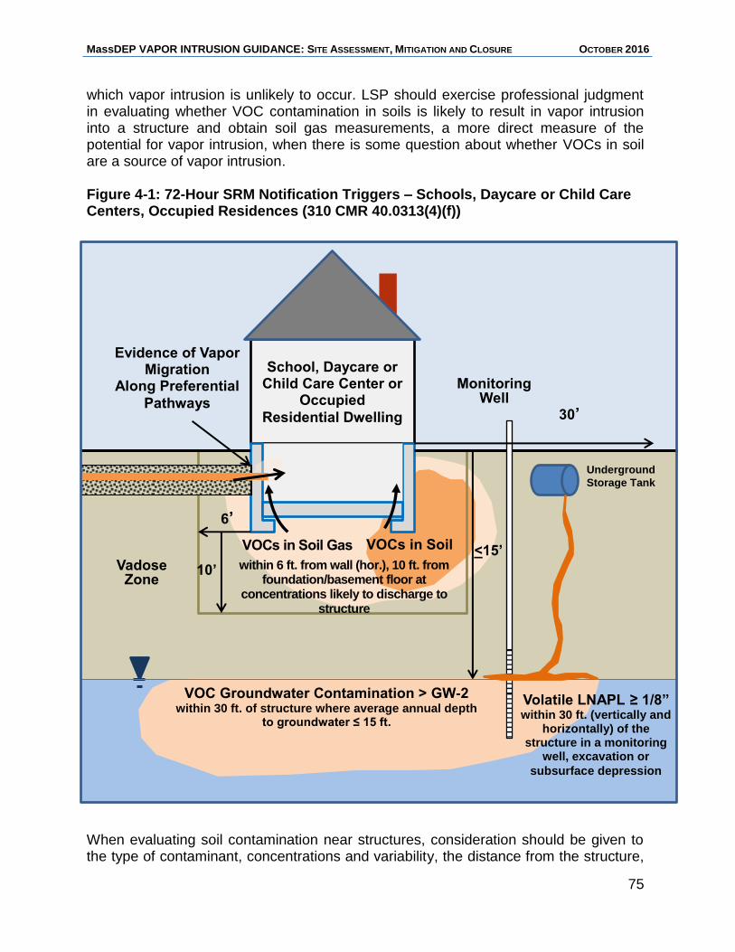
MassDEP VAPOR INTRUSION GUIDANCE: SITE ASSESSMENT, MITIGATION AND CLOSURE OCTOBER 2016
75
which vapor intrusion is unlikely to occur. LSP should exercise professional judgment in evaluating whether VOC contamination in soils is likely to result in vapor intrusion into a structure and obtain soil gas measurements, a more direct measure of the potential for vapor intrusion, when there is some question about whether VOCs in soil are a source of vapor intrusion. Figure 4-1: 72-Hour SRM Notification Triggers – Schools, Daycare or Child Care Centers, Occupied Residences (310 CMR 40.0313(4)(f))
When evaluating soil contamination near structures, consideration should be given to the type of contaminant, concentrations and variability, the distance from the structure,
l
Vadose Zone
Evidence of Vapor Migration
Along Preferential
Pathways
VOC Groundwater Contamination > GW-2 within 30 ft. of structure where average annual depth
to groundwater ≤ 15 ft.
Volatile LNAPL ≥ 1/8” within 30 ft. (vertically and
horizontally) of the structure in a monitoring
well, excavation or
subsurface depression
School, Daycare or Child Care Center or
Occupied
Residential Dwelling
VOCs in Soil Gas VOCs in Soil
within 6 ft. from wall (hor.), 10 ft. from foundation/basement floor at
concentrations likely to discharge to structure
6’
10’
30’
<15’
Monitoring Well
Underground
Storage Tank
MassDEP VAPOR INTRUSION GUIDANCE: SITE ASSESSMENT, MITIGATION AND CLOSURE OCTOBER 2016
76
soil type, and whether the soil contamination is indicative of a source at/near the structure. When VOC soil contamination is detected near structures, follow-up sub-slab soil gas sampling is warranted to determine whether vapor intrusion is likely. Sub-slab soil gas data generally provides a clearer indication of the potential for vapor intrusion than open field soil gas and soil data. Note, where VOCs detected in soil are below the Reportable Concentrations, it may be that higher concentrations of VOCs are present but have not yet been identified. In such cases additional investigation is warranted to confirm that the low concentrations of VOCs in soil are representative of the area under investigation. The investigative approach needs to ensure adequate environmental source investigation before attributing VOCs in indoor air to non-disposal site related sources. The requirement to report a Condition of SRM applies only when there is evidence associating the condition with a release “for which notification otherwise is or has at any time in the past been required in accordance with 310 CMR 40.0300” (310 CMR 40.0313(4)). This means that if groundwater or soil concentrations at the source of a release do not and have never exceeded the applicable Reportable Concentrations, and the release does not trigger other notification criteria, then a Condition of SRM would not require reporting. However, 310 CMR 40.0370 requires response actions to be undertaken for releases of OHM that do not require notification if the releases pose a significant risk to health, safety, public welfare or the environment.
4.1.3 120-Day Notifications Potentially Relevant to the Vapor Intrusion Pathway
Releases of VOCs that require notification within 120 days pursuant to 310 CMR 40.0315 may indicate conditions that are or have the potential to eventually impact the indoor air of nearby buildings. Post-notification assessment activities should include further defining whether such conditions exist and if so, whether additional notification (2-hour or 72-hour) related to vapor intrusion is required.
4.1.4 Notification and Releases to the Interior of Buildings If a release of OHM is contained within a building (i.e., the OHM never reaches the environment at a reportable level), the release is exempt from the notification under the MCP (310 CMR 40.317(19)(b)). A common example of this is a release from a leaking or overfilled free-standing fuel oil storage tank in a basement. MassDEP considers this notification exemption appropriate when a preponderance of the evidence indicates that less than the Reportable Quantity (e.g., 10 gallons for fuel oil) has reached environmental media outside the building (e.g., by flowing through cracks in a concrete basement floor or into an unlined sump) over a 24-hour period. Releases to earthen floors in buildings are releases to soil and therefore to the environment, and require notification based on the MCP’s notification requirements.
Releases that are contained within a building may result in impacts to indoor air; however, any such impacts would not be addressed under the MCP where the OHM does not otherwise impact the environment above a Reportable Quantity or Reportable Concentration.
MassDEP VAPOR INTRUSION GUIDANCE: SITE ASSESSMENT, MITIGATION AND CLOSURE OCTOBER 2016
77
4.1.5 Downgradient Property Status
Buildings affected by a vapor intrusion pathway are often located on properties downgradient of the property where the OHM contaminant plume originates (i.e., the upgradient source property). Owners of the downgradient property with potentially affected buildings may qualify for Downgradient Property Status (DPS) pursuant to the provisions at 310 CMR 40.0180. The downgradient property owner may qualify for DPS if the following conditions are met:
1. Such person has notified MassDEP of the release if notification is required pursuant to 310 CMR 40.0300;
2. The source of the contamination at the downgradient property is or was located on one or more upgradient or upstream property;
3. No act of such person has contributed to the release;
4. Such person is not be affiliated with the upgradient source property, and
5. To the extent that such person has conducted response actions, they have been conducted on compliance with the MCP.
The DPS submittal (310 CMR 40.0183(4)) must provide an evaluation of groundwater flow direction, document that the contamination affecting the building on the downgradient property is migrating from an upgradient source, and indicate on a plan the locations of any known or suspected sources of the OHM that are affecting the downgradient property. It must also include an evaluation of the need to conduct an IRA. With respect to vapor intrusion concerns, this would include whether an IRA is warranted to further assess or mitigate the vapor intrusion pathway. Persons with DPS, including DPS obtained through a Modification of a DPS Submittal (pursuant to 310 CMR 40.1087) have an ongoing obligation to provide notification and perform IRAs if conditions require such response (310 CMR 40.0184(3)). DPS has the effect of relieving the downgradient property owner from conducting Tier Classification and Comprehensive Response Actions to achieve a Permanent Solution and paying Tier I or Tier II annual compliance fees. To maintain DPS (310 CMR 40.0185), current owners of the downgradient property must: provide reasonable access to the property by persons conducting response actions (e.g., the upgradient source property owner or operator) as well as MassDEP staff and its contractors; avoid activities that would prevent or impede response actions; take reasonable steps to prevent exposure of human and environmental receptors to OHM on their property; make reasonable efforts to identify persons responsible for the release; ensure that the release is not made worse; and, if undertaking response actions, conduct them in compliance with the MCP.
MassDEP VAPOR INTRUSION GUIDANCE: SITE ASSESSMENT, MITIGATION AND CLOSURE OCTOBER 2016
78
With respect to the vapor intrusion pathway, the downgradient property owner should not make alterations to the buildings that may result in a complete pathway. Response actions undertaken by the downgradient property owner may include implementing vapor intrusion mitigation measures to eliminate an Imminent Hazard on their property where the source property owner has not been identified or is unable or unwilling to take necessary mitigation steps. 4.2 Immediate Response Actions (IRAs) IRAs must be conducted at sites that require notification to the MassDEP under the 2- or 72-hour reporting provisions of 310 CMR 40.0313 or 40.0312, including those with an IH (310 CMR 40.0412). The MCP requires that an IRA abate, prevent, or eliminate an IH (310 CMR 40.0411(1)(a)). In addition, pursuant to 310 CMR 40.0414(3), IRAs are presumed to require the elimination and/or mitigation of Critical Exposure Pathways (CEPs), as discussed further in Section 4.3. A variety of approaches for the mitigation of the vapor intrusion pathway, as described in Section 3, may be part of an IRA. An IRA conducted under the MCP requires submittal to MassDEP of an IRA Plan, IRA Status Reports and, where Active Operation and Maintenance of a remedial action is occurring (this would include use of an AEPMM), Remedial Monitoring Reports (RMRs). 4.2.1 Immediate Response Action Submittals The standard schedule for the submittal of IRA Plans and Status Reports is:
1. Submittal of a written IRA Plan within 60 days of providing oral notification of a 2-hour or 72-hour release or threat of release, knowledge of a Condition of Substantial Release Migration, or from the date that the Department issues a Notice of Responsibility for a disposal site at which an IRA is required (310 CMR 40.0420(7))or by an Interim Deadline established by MassDEP pursuant to 310 CMR 40.0167;
2. Submittal of a written IRA Status Report within 120 days after the date on which the intent to conduct the IRA was first communicated to the Department (310 CMR 40.0425(1)), and every six months thereafter, until an IRA Completion Report is submitted (310 CMR 40.0425(2)).
The frequency at which RMRs are required to be submitted in addition to Status Reports depends on the conditions being addressed by the remedial action. Initially, RMRs are required monthly if the system is addressing an IH or Condition of Substantial Release Migration; otherwise the RMR is required every six months, corresponding with the frequency of the Status Report submittal. As described below, the frequency of submitting both Status Reports and RMRs may also be reduced where certain requirements are met.
MassDEP VAPOR INTRUSION GUIDANCE: SITE ASSESSMENT, MITIGATION AND CLOSURE OCTOBER 2016
79
4.2.1.1 Reduced IRA and Status Report Frequency There are specific provisions that allow for reducing the frequency of IRA Status Reports and RMRs when the ongoing Active Operation and Maintenance of remedial action conducted as an IRA is limited to operation of an AEPMM. Pursuant to 310 CMR 40.0425(5), for disposal sites where IRAs are being taken solely to eliminate, mitigate or prevent a CEP that does not pose an IH with the use of an AEPMM, the frequency of IRA Status Reports may be reduced from every six months to annually, once the following information is submitted:
1. Results of sampling demonstrating the AEPMM is effectively maintaining, at a minimum, NSR for the Receptors of concern;
2. A list of the specific system conditions, operating parameters, and/or maintenance necessary for ensuring the ongoing effectiveness of the AEPMM in maintaining NSR for the Receptors of concern;
3. A description of a monitoring program designed to ensure the ongoing effectiveness of the AEPMM in maintaining NSR for the Receptors of concern; and
4. An LSP Opinion supporting a reduced reporting schedule pursuant to 310 CMR 40.0425(5)(b) as being adequate to document the ongoing IRAs.
Where the schedule for Status Reports is reduced pursuant to 310 CMR 40.0425(5), the frequency of RMR submittals is also reduced to an annual submittal; RMRs in such cases are to be submitted with the Status Report (310 CMR 40.0425(7)(c)). Where an AEPMM is operating to address an IH, the Department may consider and approve alternate schedules or Interim Deadlines for submitting RMRs pursuant to 310 CMR 40.0425(7)(d). In such cases, a reduced RMR schedule may be appropriate where sufficient measures have been put in place to ensure the effective monitoring of the AEPMM, such as use of remote monitoring (telemetry) on the AEPMM and/or a schedule for indoor air testing to confirm the mitigation system’s effectiveness. Where active remedial systems and/or continuing response actions are being conducted as IRAs to address an IH, the IRAs must not be terminated until the response objectives and/or approval conditions have been met and approval for termination has been obtained from the Department 310 CMR 40.0426(6). Requests to terminate these systems must be supported by data, documentation and technical information sufficient to justify the cessation of the IRA. Approval can be presumed if the Department does not issue a written approval or denial within 21 days of the receipt of the termination request.
MassDEP VAPOR INTRUSION GUIDANCE: SITE ASSESSMENT, MITIGATION AND CLOSURE OCTOBER 2016
80
4.3 Critical Exposure Pathways
The CEP requirements in the MCP ensure that timely action is taken, where feasible, to protect sensitive human receptors from exposures to disposal site-related contaminants in indoor air or in drinking water while a site is being fully assessed and actions are taken to remediate the contamination causing the exposure. Sensitive human receptors include infants, children, pregnant women, and those who are ill or have compromised immune systems in school buildings, daycares and residential dwellings. The CEP requirement reflects the benefit of taking prompt response actions to reduce the exposure of sensitive receptors in light of the toxicological uncertainties of many contaminants and the limited site information that may be available early in the MCP process, including whether concentrations may be increasing at the exposure point. When conducting an IRA, the presence of a CEP triggers consideration of expedited actions that may be feasible to eliminate or reduce the OHM exposure. As depicted in Figure 4-2 below, the requirement to address a CEP as part of an IRA applies regardless of the quantitative level of risk. Because there is a range of relatively low-cost and effective vapor intrusion pathway elimination or mitigation measures available, the Department believes that it is feasible in most cases to eliminate or reduce exposures where a CEP attributable to vapor intrusion is identified. For the purposes of CEP reporting, “vapor-phase emissions of measurable concentrations of oil and/or hazardous materials” means OHM detected in the indoor air of the living or working space of a pre-school, daycare, school or occupied residential dwelling at concentrations greater than the Residential Threshold Values (TVr) (see Appendix 1). As previously presented (Section 2.2.4), the Threshold Values were developed as a screening tool to evaluate whether VOC concentrations in indoor air may be related to the vapor intrusion pathway; they are based on MassDEP’s Typical Indoor Air Concentrations (MassDEP, 2008), MCP risk management criteria and the analytical reporting limits. While there are no TVs specifically for pre-schools, daycares or schools, the use of the TVr is appropriately conservative for sensitive receptors, and may be used as de minimus contaminant concentrations below which CEP notification requirements are not triggered.
Critical Exposure Pathways mean those routes by which oil and/or hazardous material(s) released at a disposal site are transported, or are likely to be transported, to human receptors via:
(a) vapor-phase emissions of measurable concentrations of oil and/or hazardous materials into the living or working space of a pre-school, daycare, school or occupied residential dwelling; or
(b) ingestion, dermal absorption or inhalation of measurable concentrations of oil and/or hazardous materials from drinking water supply wells located at and servicing a pre-school, daycare, school or occupied residential dwelling.
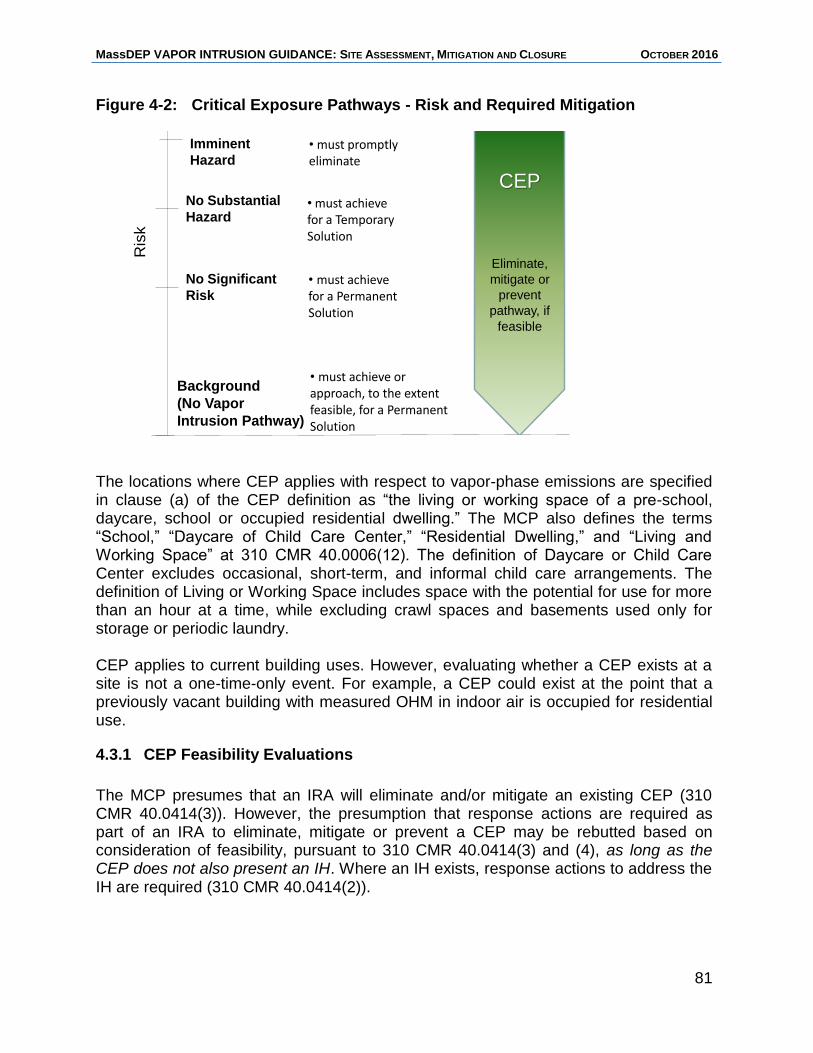
MassDEP VAPOR INTRUSION GUIDANCE: SITE ASSESSMENT, MITIGATION AND CLOSURE OCTOBER 2016
81
Figure 4-2: Critical Exposure Pathways - Risk and Required Mitigation
Risk and Required Mitigation
Ris
kImminent
Hazard• must promptlyeliminate
• must achievefor a TemporarySolution
Background
(No Vapor
Intrusion Pathway)
• must achievefor a PermanentSolution
• must achieve or approach, to the extent feasible, for a PermanentSolution
No Substantial
Hazard
No Significant
Risk
CEP
Eliminate,
mitigate or
prevent
pathway, if
feasible
The locations where CEP applies with respect to vapor-phase emissions are specified in clause (a) of the CEP definition as “the living or working space of a pre-school, daycare, school or occupied residential dwelling.” The MCP also defines the terms “School,” “Daycare of Child Care Center,” “Residential Dwelling,” and “Living and Working Space” at 310 CMR 40.0006(12). The definition of Daycare or Child Care Center excludes occasional, short-term, and informal child care arrangements. The definition of Living or Working Space includes space with the potential for use for more than an hour at a time, while excluding crawl spaces and basements used only for storage or periodic laundry. CEP applies to current building uses. However, evaluating whether a CEP exists at a site is not a one-time-only event. For example, a CEP could exist at the point that a previously vacant building with measured OHM in indoor air is occupied for residential use.
4.3.1 CEP Feasibility Evaluations
The MCP presumes that an IRA will eliminate and/or mitigate an existing CEP (310 CMR 40.0414(3)). However, the presumption that response actions are required as part of an IRA to eliminate, mitigate or prevent a CEP may be rebutted based on consideration of feasibility, pursuant to 310 CMR 40.0414(3) and (4), as long as the CEP does not also present an IH. Where an IH exists, response actions to address the IH are required (310 CMR 40.0414(2)).
MassDEP VAPOR INTRUSION GUIDANCE: SITE ASSESSMENT, MITIGATION AND CLOSURE OCTOBER 2016
82
A CEP feasibility evaluation is not required if an IRA is implemented that eliminates the CEP; the elimination of the CEP would be documented in the IRA Completion Statement. The conceptual and regulatory tenets of feasibility and feasibility evaluations are contained in the feasibility criteria found in Section 3A(h) of M.G.L. c. 21E and incorporated into the MCP at 310 CMR 40.0860. These criteria include whether or not a technology exists, expertise is available, a disposal location (if needed for the remedy) is available, and whether the costs of the remedial action outweigh the benefits (cost-benefit analysis). Additional guidance on these criteria is provided in MassDEP Policy #WSC-04-160, Conducting Feasibility Evaluations under the MCP. As stated at 310 CMR 40.0860(7)(a), in a cost-benefit analysis the benefits of a remedial action are considered to justify the costs unless “the incremental cost of conducting the remedial action alternative is substantial and disproportionate to the incremental benefit of risk reduction, environmental restoration, and monetary and non-pecuniary values.” Sections 4.3.2 and 4.3.3 identify response actions that MassDEP considers to be generally feasible and generally infeasible, respectively, when conducting response actions to address CEPs related to vapor intrusion. Section 4.3.4 lists factors to be considered when rebutting the presumption for taking action to eliminate or mitigate a CEP as part of an IRA. Figure 4-3 illustrates how considerations of feasibility are incorporated into the decision-making process at sites where a CEP has been identified.
4.3.2 Generally Feasible Response Actions to Address CEP
The installation of an active SSD system is generally considered a technologically feasible and cost-effective approach to eliminate a CEP. The feasibility of this approach may be rebutted with a CEP feasibility evaluation based on site-specific considerations such as environmental and/or building characteristics. The rebuttal of the presumption for CEP elimination or mitigation with an active SSD system must include a CEP feasibility evaluation to determine which, if any, response actions are feasible to eliminate the CEP. If it is determined that it is not feasible to eliminate the CEP, the feasibility study must also include an evaluation of the feasibility of response actions to mitigate the CEP by reducing the concentration of OHM exposure to the extent feasible (see Section 4.3.3).
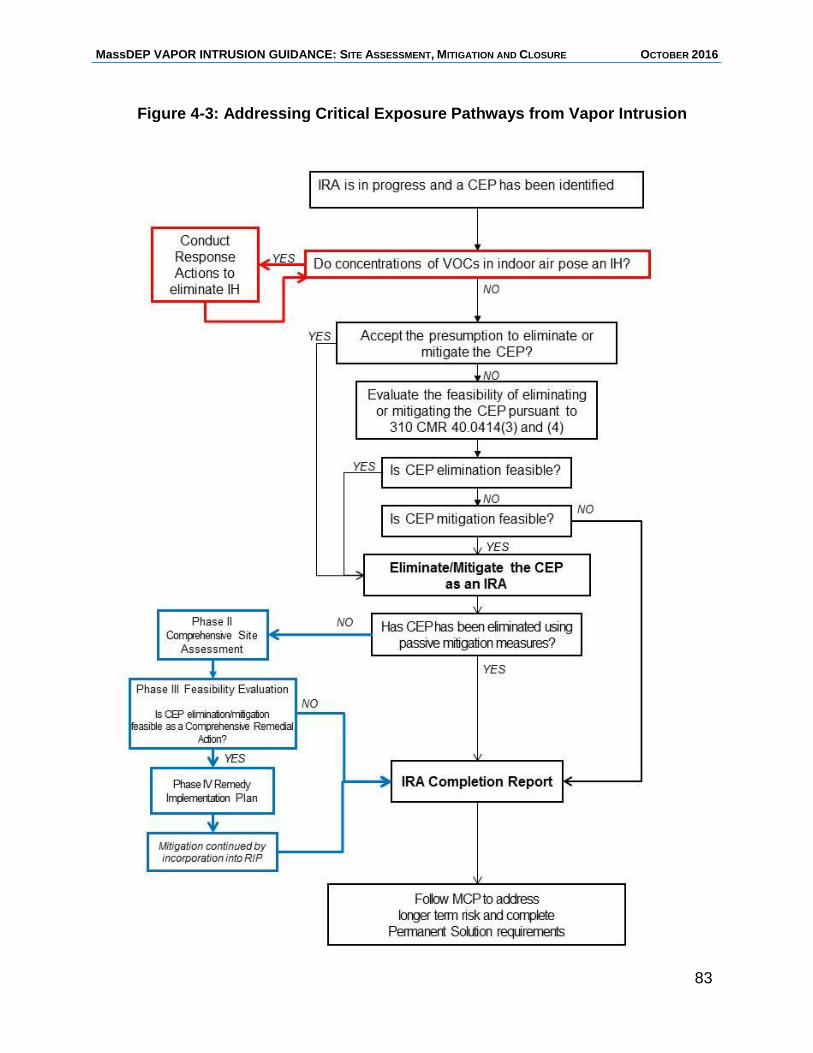
MassDEP VAPOR INTRUSION GUIDANCE: SITE ASSESSMENT, MITIGATION AND CLOSURE OCTOBER 2016
83
Figure 4-3: Addressing Critical Exposure Pathways from Vapor Intrusion
MassDEP VAPOR INTRUSION GUIDANCE: SITE ASSESSMENT, MITIGATION AND CLOSURE OCTOBER 2016
84
4.3.3 Generally Infeasible Response Actions to Address CEP
At owner-occupied residences with a CEP where VOCs in the indoor air are below a level of No Significant Risk, MassDEP considers response actions to eliminate or mitigate CEP conditions to be infeasible if the owner-occupant will not agree to allow actions to address the CEP conditions. In such instances, documentation of the PRP/LSP’s efforts to conduct measures to address CEP conditions at the residence should be provided in the CEP feasibility evaluation.
4.3.4 Rebutting the MCP Presumption for CEP Elimination/Mitigation
Where there is no IH condition, the PRP may rebut the presumption of the need for response actions as part of an IRA to address a CEP (310 CMR 40.0414) based upon a showing by a preponderance of evidence that such response actions are not feasible, using the feasibility criteria outlined in 310 CMR 40.0860. The feasibility evaluation includes a cost/benefit analysis to determine whether the costs of eliminating or mitigating the CEP would be substantial and disproportionate to the benefits. Note that this CEP feasibility evaluation only addresses actions to be taken as part of an IRA. The feasibility of eliminating the CEP and the feasibility of mitigating the CEP must be evaluated separately and sequentially pursuant to 310 CMR 40.0414(3), which codifies a preference for eliminating exposure to sensitive populations overly reducing such exposures. The feasibility of CEP mitigation is evaluated only if elimination of the CEP is determined not to be feasible. The feasibility of CEP elimination and the feasibility of CEP mitigation should be evaluated and documented in a similar manner (Figure 4-3). CEP feasibility evaluations should consider the following in regard to the risk-reduction benefits of eliminating or mitigating a CEP:
the health benefits of quick reductions in exposure, especially when the site-related OHM have high toxicity and/or persistence;
the uncertainty of the current risk estimates considering the quality/quantity of available data; and
the likelihood that vapor intrusion pathway elimination or mitigation will be needed to achieve NSR and a Permanent Solution.
Site-specific costs that may affect the feasibility of eliminating or mitigating a CEP could be an issue at buildings that require: reconstruction of basement walls or pouring of new slabs; installation of raised floors for SSD system installation due to the presence of a high groundwater table; or an excessive number of extraction points and fans due to poor sub-slab communication with the area of known contamination. Increased costs alone would not necessarily support a conclusion that CEP elimination or mitigation activities are not feasible, as these costs must be weighed against the benefits provided by the risk reduction.
MassDEP VAPOR INTRUSION GUIDANCE: SITE ASSESSMENT, MITIGATION AND CLOSURE OCTOBER 2016
85
The costs of operation and maintenance a mitigation system for a period of 3 to 5 years (the time typically taken to complete a Phase II Comprehensive Site Assessment and attain a Permanent or Temporary Solution) should be included in the feasibility evaluation, as well as the benefits from risk reduction accrued over the same period of time. If the subsequent Phase II Assessment concludes that Comprehensive Remedial Actions are required to achieve a Permanent or Temporary Solution (i.e., a Condition of No Significant Risk has not been achieved), a comprehensive Phase III evaluation of remedial alternatives must be conducted. Where remedial actions are necessary to achieve a Permanent Solution, the Phase III evaluation must consider alternatives for achieving NSR and reducing OHM in the environment to Background concentrations to the extent feasible.
4.3.5 Documentation of a CEP Feasibility Evaluation
A CEP feasibility evaluation is not required if an IRA is implemented that eliminates the CEP. Documentation of the elimination of the CEP in such case would be included in the IRA Completion Statement. Otherwise, where a feasibility evaluation is required, appropriate documentation of the feasibility evaluation should be provided in the relevant response action submittal(s). Documentation for a CEP feasibility evaluation should include:
1. a description of the CEP as it relates to the disposal site Conceptual Site Model;
2. a list of measures evaluated to prevent, eliminate or mitigate the CEP;
3. estimated costs of the measures evaluated and an explanation of how the costs were determined;
4. an evaluation of the relative effectiveness of each measure or combination of measures considered;
5. a description of the basis for determining whether the measures are feasible or infeasible; and
6. a statement identifying the measure or combination of measures chosen to address the CEP, if any.
The documentation should distinguish between the feasibility evaluation for eliminating CEP and that for mitigating CEP. The recommendation documented in a CEP feasibility evaluation may result in response actions to eliminate and/or mitigate the CEP, or it may result it no action being taken as part of an IRA (in cases where it is not feasible to eliminate or mitigate the CEP). An IRA Completion Report would be submitted in cases where addressing a CEP is determined to be infeasible and no response actions are otherwise being performed as an IRA. CEP feasibility evaluations usually address affected buildings individually. It is important to distinguish between CEP feasibility evaluations and Phase III feasibility evaluations, which are performed following Phase II Assessments concluding that response actions
MassDEP VAPOR INTRUSION GUIDANCE: SITE ASSESSMENT, MITIGATION AND CLOSURE OCTOBER 2016
86
are needed to achieve a level of No Significant Risk at a site. Phase III feasibility evaluations consider the feasibility of implementing various remedial alternatives at the entire site comprehensively, especially in terms of addressing the source of the contamination.
4.3.6 CEP Closure - Immediate Response Action Completion (IRAC) Criteria and Possible Outcomes
The requirements for closure of IRAs are specified at 310 CMR 40.0427. An IRA is considered complete and an IRA Completion Report (IRAC) can be submitted when the condition which gave rise to the need for the IRA has been assessed and, where necessary, remediated in a manner and to a degree that will ensure: (a) that the site is stabilized; (b) IHs are addressed without the continued operation and maintenance of Active Remedial Systems, AEPMMs or by the incorporation of ongoing response actions to eliminate or control the IH into the Phase IV Remedy Implementation Plan for the disposal site, and (c) time-critical measures addressing the elimination, prevention or mitigation of CEP(s) have been completed. As required by 310 CMR 40.0427(1)(c), one of four conditions must be met and documented in a LSP Opinion to support the completion of response actions to address a CEP. At vapor intrusion sites where multiple buildings and properties are impacted, each property must meet one of the four conditions. These conditions are:
1. the CEP has been eliminated using passive measures;
2. a feasibility study, as specified at 310 40.0414(3) and (4), supports the conclusion that it is not feasible to eliminate, prevent, or mitigate the CEP (and an IH or condition of significant risk is not present);
3. a feasibility study, conducted as part of a Phase III evaluation of Comprehensive Remedial Alternatives as specified in 310 CMR 40.0860, supports the conclusion that it is not feasible to eliminate, prevent, or mitigate the CEP(s) as part of the Comprehensive Remedial Alternative; or
4. mitigation of CEP(s) is continuing by incorporation of ongoing response actions to address the CEP(s) into the Phase IV Remedy Implementation Plan for the disposal site.
These four conditions are points at which an IRA implemented to address the CEP may be closed and are discussed in more detail below. 4.3.6.1 CEP Elimination is Feasible When the CEP condition has been eliminated using passive measures (see Section 3.5), an IRAC Report may be submitted to document the completion of the IRA activities related to eliminating the CEP. The conclusion that CEP has been eliminated must be supported by indoor air data. Table 3-2 provides recommended sampling to demonstrate effectiveness for passive measures. The IRAC Report can be submitted regardless of the status of other response action activities, assuming there are no other
MassDEP VAPOR INTRUSION GUIDANCE: SITE ASSESSMENT, MITIGATION AND CLOSURE OCTOBER 2016
87
conditions that must be addressed under the IRA. Following submittal of an IRAC Report, ongoing assessment and remediation would continue at the site under the MCP process (Figure 4-3). If the CEP condition has been eliminated with the ongoing operation of an Active Remedial System or AEPMM, an IRAC may not be submitted until after the completion of a Phase II Comprehensive Site Assessment. In cases where the operation of the Active Remedial System or AEPMM is to be continued as part of Comprehensive Remedial Actions, the IRAC Report would be submitted after a Phase III evaluation and selection of a Comprehensive Remedial Action Alternative has been conducted and in conjunction with the Phase IV Remedial Implementation Plan (i.e., the IRA is closed when the ongoing operation of the system is managed as part of the Phase IV Comprehensive Remedial Alternative). The conclusion that CEP has been eliminated through the effective operation of an Active Remedial System or AEPMM must be supported by indoor air data. Table 3-1 provides recommended sampling to demonstrate effectiveness for active mitigation measures. 4.3.6.2 It is not Feasible to Eliminate or Mitigate CEP When vapor intrusion does not pose an IH, a CEP feasibility evaluation may be undertaken to rebut the presumption for conducting IRA response actions to address the CEP condition, as discussed in Section 4.3.4.One possible result of the CEP feasibility evaluation may be that neither elimination nor mitigation of the CEP is feasible, based on consideration of anticipated benefits and costs. In this situation, an IRAC Report would be submitted to document that conclusion. Following submittal of an IRAC Report, ongoing assessment and remediation would continue at the site under the MCP process (Figure 4-3). Long-term risk from the CEP condition would need to be part of the disposal site-wide evaluation of Comprehensive Remedial Alternatives in the Phase III feasibility evaluation. 4.3.6.3 CEP Elimination is not Feasible, but CEP Mitigation is Feasible If the CEP feasibility evaluation concludes that CEP elimination was not feasible (i.e., the vapor intrusion impacts cannot be completely interrupted or prevented), but CEP mitigation that results in the reduction of OHM in indoor air is feasible, mitigation activities would be required. These activities should be evaluated and monitored for effectiveness with consideration given to the sampling recommendations outlined in Tables 3-1 and 3-2. If monitoring indicates that the concentration of VOCs in indoor air are above a level of NSR without continued operation of the mitigation system, the CEP mitigation would need to be continued and may be incorporated into Comprehensive Response Actions for the disposal site (see Section 4.3.6.4). 4.3.6.4 CEP Mitigation is Incorporated into Comprehensive Response Actions Ongoing response actions to monitor and mitigate CEP conditions will generally be incorporated into the Comprehensive Response Actions for the disposal site, including
MassDEP VAPOR INTRUSION GUIDANCE: SITE ASSESSMENT, MITIGATION AND CLOSURE OCTOBER 2016
88
a Phase II Comprehensive Site Assessment and a Phase III Identification, Selection and Evaluation of Comprehensive Remedial Action Alternatives. The IRA addressing CEP may be closed with an IRAC Report upon submittal of a Phase IV Remedy Implementation Plan. The IRAC Report cannot be submitted before the Phase III feasibility evaluation if response actions that were taken involve ongoing operation of an Active Remedial System or AEPMM to eliminate or mitigate a CEP. If the CEP condition hasn’t been eliminated, the IRA could continue to mitigate the CEP during Phase II and Phase III until the Phase III feasibility evaluation is completed. If initial testing results indicate that the CEP mitigation is effective, continued monitoring may be performed as part of Phase IV activities. The continued operation of the mitigation measure would move forward as part of Comprehensive Response Actions. 4.3.6.5 CEP Elimination or Mitigation is Concluded with a Permanent Solution
for a Portion of a Disposal Site It is possible to achieve a Partial Permanent or Temporary Solution on downgradient properties at sites where contaminated groundwater migrating off the source property has impacted the indoor air of buildings at downgradient properties. In such cases, the requirements for Permanent and Temporary Solutions outlined in 310 CMR 40.1003 must be achieved for the entire site (specifically the requirement related for Source Elimination and Control, Migration Control and NAPL (310 CMR 40.1003(5) through (7)), with or without the post-closure operation of an AEPMM. These determinations must be based on adequate data collected to reflect temporal variability of VOC concentrations in indoor air, sub-slab soil gas, and groundwater considering the recommended sampling to support closure provided in Tables 3-1 and 3-2, as applicable. For more discussion of Permanent and Temporary Solution requirements, see Section 4.6.
4.4 Tier Classification and the Indoor Air Pathway
Unless a Permanent or Temporary Solution Statement submittal is filed, a disposal site must be classified as either a Tier I or Tier II within one year from the initial release notification. The Tier Classification process includes the completion of a Phase I Initial Site Investigation Report and comparison of site conditions with the Tier I Criteria established at 310 CMR 40.0520(2). With regard to the vapor intrusion pathway, disposal sites are classified as Tier I if it is determined that conditions at the site meet one or more of the criteria specified at 310 CMR 40.0520(2), which includes:
concentrations of OHM in indoor air pose an IH (310 CMR 40.0520(2)(b));
one or more remedial actions are required as part of an IRA to address the indoor air pathway (310 CMR 40.0520(2)(c)); or
there is an IRA ongoing (whether it involves assessment or remedial actions) to eliminate or mitigate a CEP related to vapor intrusion (310 CMR 40.0520(2)(d)).
MassDEP VAPOR INTRUSION GUIDANCE: SITE ASSESSMENT, MITIGATION AND CLOSURE OCTOBER 2016
89
These criteria generally reflect conditions that may be indicative of a higher level of risk or warrant closer oversight by the Department. Disposal sites that do not meet any of the Tier I Criteria are classified as Tier II disposal sites.
4.4.1 Reclassification after an Initial Tier Classification
Pursuant to 310 CMR 40.0530(1), at any point new or additional data is obtained after the initial Tier Classification that is reasonably likely to result in a reclassification of a disposal site from Tier II to Tier I, the disposal site must be re-evaluated using the Tier I Criteria at 310 CMR 40.0520(2). Reclassification of a disposal site from Tier II to Tier I must occur within 60 days of obtaining knowledge that the disposal site meets the Tier I Criteria (310 CMR 40.0530(2)). Reclassification may be done to downgrade a disposal site from Tier I to Tier II at any point that the disposal site is determined to no longer meet any of the Tier I Criteria (310 CMR 40.0530(3)).
Example Vapor Intrusion Scenario 1
At the time of the initial Tier Classification based on a Phase I Site Investigation, a disposal site was classified as Tier II because it was determined that none of the Tier I Criteria at 310 CMR 40.0520(2) applied. During subsequent site characterization, VOCs were detected above GW-2 Standards within 30 feet of an occupied Residential Dwelling where the depth to groundwater was 10 feet and a 72-hour notification was made for this Condition of SRM. An assessment–only IRA was undertaken. Thus far, reclassification of the disposal site is not required because the IRA did not include remedial actions (no containment or removal actions were taken) and no other Tier I criteria are (as of yet) met. Additional assessment performed as part of the IRA (collection of sub-slab soil gas and indoor air samples) reveals OHM in indoor air attributable to the disposal site (measurable concentrations in Living or Working Space) and therefore a CEP is present; IRA activities are ongoing to address the CEP. At this point, the disposal site must be reclassified as Tier I within 60 days of obtaining such knowledge, pursuant to 310 CMR 40.530(2).
MassDEP VAPOR INTRUSION GUIDANCE: SITE ASSESSMENT, MITIGATION AND CLOSURE OCTOBER 2016
90
4.5 Comprehensive Response Actions at Vapor Intrusion Sites
4.5.1 Conducting Phase III Feasibility Evaluations
Section 3A of M.G.L. c. 21E defines Permanent Solutions as including measures that reduce to the extent possible the level of OHM in the environment to the level that would exist in the absence of the site of concern, where feasible. Therefore, at disposal sites and portions of disposal sites (which would include buildings impacted by vapor intrusion) implementation of a Permanent Solution must include a measure or measures designed to reduce to the extent possible the level of OHM in the environment to Background, where feasible, except where it can be demonstrated that Background levels have been met, as specified at 310 CMR 40.1020. The criteria for feasibility evaluations are described in 310 CMR 40.0860; guidance on feasibility evaluations is provided in MassDEP Policy #WSC-04-160, Conducting Feasibility Evaluations under the MCP. For sites where the elimination/mitigation of a CEP was determined to be feasible and initiated as an IRA prior to conducting the Phase III evaluation, (see Section 4.3.1), the subsequent comprehensive Phase III feasibility evaluation should consider those elimination/mitigation measures in the context of the overall remedy that is developed as the Comprehensive Remedial Alternative to achieve a Permanent Solution. The Phase III feasibility evaluation should address both the feasibility of remedial alternatives to achieve NSR and a Permanent Solution, including measures to remediate or control Sources of OHM, as well as the feasibility of achieving or approaching Background. The Phase III feasibility evaluation may conclude that continuation of the CEP elimination/mitigation measures as part of Comprehensive Response Actions (see below) is feasible and should be continued as part of the comprehensive remedy or, the Phase III may conclude that the costs of continued vapor intrusion mitigation outweigh the benefits and therefore, is no longer feasible (see Figure 4-3). For disposal sites with a vapor intrusion pathway that does not represent an IH or CEP condition (i.e., a non-IH condition of vapor intrusion at commercial/industrial buildings where evaluation of the feasibility of addressing the pathway was not previously required as part of an IRA), the Phase III feasibility evaluation would address the vapor intrusion pathway along with all other conditions at the site as part of the Identification, Evaluation and Selection of Comprehensive Remedial Alternatives. In some circumstances, the necessary and appropriate actions initially taken to address IH or CEP conditions are of a short-term or temporary nature, such as the use of any mechanical devices to over-pressurize a living space, running APUs, operational changes to HVAC systems, sealing sumps and cracks in walls and foundations. The efficacy and permanence of these actions would need to be evaluated prior to the submittal of a Permanent or Temporary Solution Statement, and included in the Phase III evaluation. As discussed in Section 3, a Permanent Solution cannot rely upon the
MassDEP VAPOR INTRUSION GUIDANCE: SITE ASSESSMENT, MITIGATION AND CLOSURE OCTOBER 2016
91
use of APUs or operational changes to building ventilation to maintain NSR because such measures are not sufficiently reliable or suitable for long-term mitigation.
4.5.2 Transitioning Preliminary Response Actions to Comprehensive Response Actions
IRAs are required at vapor intrusion sites to address an IH, or SRM/CEP conditions. At disposal sites where IRAs are not otherwise triggered (e.g., VOC concentrations below IH levels at locations that do not meet the definition of CEP such as industrial or commercial buildings), a RAM may be used to address the vapor intrusion pathway. Because RAMs may be performed at any point in the response action process, they may be used to initiate vapor intrusion mitigation prior to the completion of Phase II and Phase III (both of which must be completed before implementation of a Comprehensive Remedial Alternative in Phase IV). MassDEP encourages consideration of early actions to initiate vapor intrusion mitigation. If the IRA or RAM is not completed prior to the implementation of the Comprehensive Remedial Alternative, the IRA/RAM response action may be incorporated into the Comprehensive Remedial Alternative recommended following a Phase II Assessment and a Phase III Evaluation of Comprehensive Remedial Alternatives (310 CMR 40.0429(3)). With the submittal of a Phase IV Remedy Implementation Plan (310 CMR 40.0874) and an IRA or RAM Completion Statement, the IRA or RAM will be considered completed, and the ongoing operation of the vapor intrusion mitigation system would continue as part of Comprehensive Response Actions.
4.5.3 Phase IV and Phase V Comprehensive Response Actions
Comprehensive Response Actions to address the vapor intrusion pathway may have been initiated as IRAs or RAMs or may be initiated following a Phase III Evaluation as part of Phase IV – Implementation of the Selected Remedial Alternative and Phase V - Operation, Maintenance and/or Monitoring activities. The operation and maintenance of Comprehensive Remedial Alternatives is documented in the Remedy Implementation Plan and/or an Operation, Maintenance
Example Vapor Intrusion Scenario 2 An SSD system was installed at a commercial building to mitigate IH concentrations of VOCs in indoor air. Because the system alone did not adequately reduce indoor air contaminant levels, the HVAC system was adjusted to take in more fresh air. The HVAC system modification is not an acceptable long-term option to achieve a Permanent Solution. It should be considered only a temporary measure in the Phase III evaluation and selection of Comprehensive Remedial Alternatives.
MassDEP VAPOR INTRUSION GUIDANCE: SITE ASSESSMENT, MITIGATION AND CLOSURE OCTOBER 2016
92
and/or Monitoring Plan. Phase IV Status Reports are required if Active Operation and Maintenance of a remedial action is conducted prior to the submittal of a Final Inspection Report and Phase IV Completion Statement. Upon completion of Phase IV activities, possible outcomes include: (a) submittal of a Permanent Solution Statement; (b) submittal of a Permanent Solution with Conditions Statement, for sites with AEPMMs; (c) submittal of a Temporary Solution Statement; or (d) continuation of remedial actions as operation and maintenance of the Comprehensive Response Action under Phase V, which includes worked performed under ROS. 4.5.3.1 Remedy Operation Status ROS is a regulatory status within Phase V that is an option for conducting Comprehensive Response Actions at disposal sites where Active Operation and Maintenance is underway for the purpose of achieving a Permanent Solution. As specified at 310 CMR 40.0893(2), qualifying for and maintaining ROS requires: that the remedy be designed to achieve the requirements of a Permanent Solution; source elimination or control; the elimination of substantial hazards; the submittal of Status and Remedial Monitoring Reports; and meeting requirements for any AEPMMs employed as part of the remedy. ROS is effective upon submission of the Remedy Operation Status Submittal pursuant to 310 CMR 40.0893(3). ROS has the effect of suspending the five-year deadline for achieving a Permanent or Temporary Solution and Tier Classification Extensions are not required while ROS is maintained. See Section 4.7.4.1 for operation and reporting requirements when an AEPMM is implemented as part of ROS. ROS is an appropriate option for disposal sites where the Active Operation and Maintenance of an Active Remedial System or Active Remedial Monitoring Program designed and implemented to achieve a Permanent Solution is ongoing. That is, the remedy that has been selected and implemented is one that will eventually, with continued operation and/or monitoring, remediate the disposal site to a condition that meets the requirements of a Permanent Solution. In the case of vapor intrusion sites, ROS may apply to disposal sites where an Active Remedial System is being operated to eliminate/control the source of OHM and/or controlling plume migration or where an Active Remedial Monitoring Program (e.g., monitored natural attenuation) is being conducted to document the reduction of contaminant concentrations over time. Where a complete vapor intrusion pathway is present, an AEPMM can be operated as part of the Comprehensive Response Actions conducted under Remedy Operation Status. 4.6 Requirements and Considerations for Closure at Sites with Vapor Intrusion
Pathways or Concerns This section of the guidance addresses aspects related to MCP closure for disposal sites with vapor intrusion pathways, including considerations for assessments and submittals provided in support of Permanent and Temporary Solutions, and the requirements of and distinction between Permanent Solutions and Temporary Solutions related to disposal sites with vapor intrusion concerns.
MassDEP VAPOR INTRUSION GUIDANCE: SITE ASSESSMENT, MITIGATION AND CLOSURE OCTOBER 2016
93
Requirements to achieve and document a Permanent or Temporary Solution are provided in 310 CMR 40.1000. The General Provisions for Permanent and Temporary Solutions are listed at 310 CMR 40.1003 and the performance standards are listed at 310 CMR 40.1004. Both Permanent and Temporary Solutions achieved at a disposal site must be supported by assessments and evaluations that demonstrate that the requirements at 310 CMR 40.1000 have been met. Such assessments and evaluations must be:
of sufficient scope, detail, and level of effort to characterize the risk of harm to health, safety, public welfare and the environment posed by the site or disposal site pursuant to 310 CMR 40.0900;
consistent with the Response Action Performance Standard described in 310 CMR 40.0191; and
commensurate with the nature and extent of the release or threat of release and complexity of site conditions.
Assessments and evaluations conducted to achieve a Permanent or Temporary Solution must be supported by the disposal site CSM and any findings that are inconsistent or contrary to the CSM must be adequately explained. A succinct summary of the CSM for the disposal site is required as part of the Permanent (310 CMR 40.1056(2)(b)) and Temporary (310 CMR 40.1057(2)(b)) Solution Statements. Further, a Data Usability Assessment and Representativeness Evaluation must be conducted and documented as part of these submittals that demonstrate, respectively, that the data relied upon to support the Permanent or Temporary Solution is of sufficient precision, accuracy and completeness, and provide adequate spatial and temporal information to support the conclusion that a Permanent or Temporary Solution has been achieved. To meet the requirements for a Permanent or Temporary Solution for the entire disposal site, the Permanent or Temporary Solution Statement must document:
the delineation of the extent of contamination in all affected media;
a risk characterization that documents whether NSR or NSH exists or has been achieved;
for Temporary Solutions, whether remedial actions are necessary to achieve NSR and whether it is feasible to achieve a Permanent Solution;
for Permanent Solutions, if remedial actions were taken to achieve NSR, information on the extent to which OHM levels have been reduced to Background or the results of a feasibility evaluation indicating the achievement of Background is not feasible;
that Sources of OHM contamination have been adequately identified, characterized, and eliminated or controlled (310 CMR 40.1003(5));
MassDEP VAPOR INTRUSION GUIDANCE: SITE ASSESSMENT, MITIGATION AND CLOSURE OCTOBER 2016
94
the migration of subsurface OHM (dissolved OHM in groundwater and vapor-phase OHM in the vadose zone) has been assessed and determined to be stable or contracting (Permanent Solution; 310 CMR 40.1003(6)(a)) and/or otherwise controlled or mitigated (Temporary Solution;310 CMR 40.1003(6)(b)); and
the nature, extent and mobility of any NAPL have been adequately assessed and where necessary, remedial actions have been taken to adequately contain or remove NAPL (310 CMR 40.1003(7)).
To support a Permanent or Temporary Solution at a disposal site with vapor intrusion, the disposal site assessment must demonstrate that site conditions are stable and will not worsen. For a Permanent Solution, there must be adequate data to support the conclusion that contaminant concentrations in indoor air affected by releases at the disposal site will remain at or below a level of NSR. Analytical data obtained prior to site closure must be robust enough to: demonstrate that the concentrations of COCs in groundwater, soil gas, and indoor air are stable or decreasing; that further degradation of COCs is unlikely to result in unacceptable levels of exposure to more toxic compounds (such as PCE breakdown to TCE); and identify whether contamination remaining in groundwater and/or soil gas could impact indoor air in the future as the result of changes to building conditions from aging or renovation.
The temporal variability associated with vapor intrusion disposal sites add a level of complexity to documenting that the closure requirements have been met. This variability generally warrants a more robust sampling plan over a longer period of time than is necessary at disposal sites without a vapor intrusion pathway.
The burden of proof to demonstrate that the source elimination and control requirement has been met is significantly greater at disposal sites with elevated concentrations in soil and/or groundwater or NAPL remaining than at those disposal sites with lower concentrations of residual contamination, as elevated concentrations may indicate inadequate source control. 4.6.1 Closure at a Portion of a Disposal Site The Permanent and Temporary Solution provisions may be applied to the entire disposal site (i.e., the entire area where the contamination has come to be located) or a portion of disposal. A building affected by vapor intrusion could represent a portion of a larger disposal site. Achievement of a Permanent or Temporary Solution for a portion of a disposal site requires the delineation and assessment of the full nature and extent
Remedial measures that maximize reduction of the VOC contamination source, reduce groundwater contaminant concentrations, and minimize downgradient migration are the most effective means of reducing the potential for long-term vapor intrusion impacts to both existing and future buildings.
MassDEP VAPOR INTRUSION GUIDANCE: SITE ASSESSMENT, MITIGATION AND CLOSURE OCTOBER 2016
95
of the disposal site, and demonstrating the applicable Source Elimination and Control, Migration Control and NAPL closure requirements for the disposal site have been met (310 CMR 40.1003(5) through (7)).
4.6.2 Closure Prior to Tier Classification at Sites with Vapor Intrusion Mitigation
Disposal sites with a vapor intrusion pathway are generally too complex to achieve Permanent Solutions prior to Tier Classification (i.e., within one year from notification). The assessment of vapor intrusion impacts typically involves multiple rounds of sampling over time to account for temporal/seasonal fluctuations in concentrations of VOCs in groundwater, soil gas, and indoor air and/or fluctuations in groundwater elevations. Temporal/seasonal sampling for indoor air characterization also includes sampling during worst case conditions (see Section 2.2.4 and Table 2-1), which likely precludes achieving closure within one year. However, there may be vapor intrusion sites with small, discrete OHM sources and relatively simple CSMs where it is possible to support a Permanent or Temporary Solution prior to Tier Classification. For example, prompt removal or treatment of contaminated soil in the case of a sudden release that impacts a discrete and limited area of subsurface soil may be successful in eliminating a source of vapor intrusion which can be confirmed through adequate assessment following such remedial actions. 4.7 Permanent Solutions and Temporary Solutions
The specific requirements for Permanent or Temporary Solutions vary and an understanding of these requirements, including ongoing obligations under the MCP, is necessary when evaluating which type of Solution is feasible and appropriate for a disposal site. The specific category of Permanent Solution achieved at the disposal site, or portion of a disposal site, reflects whether specific ongoing obligations for the maintenance of disposal site conditions and/or adherence to post-Permanent Solution procedures related to future activities at the disposal site apply. In addition, persons conducting response actions should understand that a Temporary Solution is a milestone in the response action process, not an endpoint.
Factors relevant to the different categories of Permanent Solutions and Temporary Solutions are outlined in 310 CMR 40.1030 and include whether:
the disposal site poses NSR;
all Substantial Hazards posed by the disposal site have been eliminated;
the risk characterization relies upon assumed limitations on current or future conditions, activities or uses, and includes the implementation of Active Exposure Pathway Mitigation Measures or Passive Exposure Pathway Mitigation Measures;
MassDEP VAPOR INTRUSION GUIDANCE: SITE ASSESSMENT, MITIGATION AND CLOSURE OCTOBER 2016
96
one or more AULs are required under the provisions of 310 CMR 40.1012 to maintain NSR or NSH;
concentrations of oil and/or hazardous material at a site exceed Upper Concentration Limits in Soil and Groundwater listed at 310 CMR 40.0996(7); and
site conditions are consistent with Natural or Anthropogenic Background.
Permanent Solutions apply to disposal sites where: a level of NSR exists or has been achieved (310 CMR 40.0900); all Sources of OHM contamination have been eliminated or controlled (310 CMR 40.1003(5)(a) and (b)); control of plumes of dissolved OHM in groundwater and vapor-phase OHM in the Vadose Zone has been achieved (310 CMR 40.1003(6)(a)); NAPL, if present, has been addressed (310 CMR 40.1003(7)(a)); all threats of release have been eliminated; and, where remedial actions have been conducted, the concentration of OHM concentrations in the environment have been reduced to as close to Background levels as feasible. Temporary Solutions apply to disposal sites where a Phase III evaluation has concluded that either response actions to achieve a Permanent Solution are not currently feasible or response actions to achieve a Permanent Solution are feasible and are being continued toward a Permanent Solution. Temporary Solutions require that: a condition of NSH exists or has been achieved (310 CMR 40.0950); all Sources of OHM Contamination have been identified, characterized, and to the extent feasible, eliminated or controlled (310 CMR 40.1003(5)(a) and (c)); control of plumes of dissolved OHM in groundwater and vapor-phase OHM in the Vadose Zone has been achieved to the extent feasible (310 CMR 40.1003(6)(b)); and (d) NAPL, if present, has been addressed (310 CMR 40.1007(b)).
As specified at 310 CMR 40.1040(2)(a), disposal sites are not eligible for a Permanent Solution if ongoing Active Operation and Maintenance of an Active Remedial System or an Active Remedial Program is required (i.e., if remedies that involve containment, removal or treatment of Sources of OHM or plume control, or monitoring toward the achievement of the Permanent Solution performance standards are still ongoing). A Permanent Solution with Conditions may be achieved, however, if the ongoing Active Operation and Maintenance is limited to the operation of an AEPMM pursuant to the requirements at 310 CMR 40.1025.
A soil vapor extraction system removing contaminant mass from the source, and may also be providing a mitigating effect on the vapor intrusion pathway, would not be eligible for a Permanent Solution with Conditions because it is operating as an Active Remedial System. As discussed in Section 3, air purifying units are also not considered AEPMMs because they are not appropriate for long-term operation as a pathway mitigation measure.
A turbine ventilator used as an added component to passive sub-slab ventilation system would not make the system an AEPMM (i.e., make it "active") unless it is
MassDEP VAPOR INTRUSION GUIDANCE: SITE ASSESSMENT, MITIGATION AND CLOSURE OCTOBER 2016
97
determined to be necessary to achieve of a level of NSR. Otherwise, SSV systems are considered Passive Exposure Pathway Mitigation Measures.
The terms Active Operation and Maintenance, Active Remedial System, Active Remedial Monitoring Program, Exposure Pathway Mitigation Measures and Active Exposure Pathway Mitigation Measure are defined at 310 CMR 40.0006(12).
4.7.1 Permanent Solutions with No Conditions As outlined in 310 CMR 40.1041(1), a Permanent Solution with No Conditions applies to a disposal site or portion of a disposal site where a level of NSR exists and will be maintained for all current and foreseeable future use of the site without relying upon: (1) assumed limitations on current or future site activities, uses or conditions that require an AUL as specified in 310 CMR 40.1012(2)); or (2) assumed limitations on current or future site activities, uses or conditions, that do not require an AULs pursuant to 310 CMR 40.1013. For disposal sites where a vapor intrusion pathway has been identified, a Permanent Solution with No Conditions would apply where the presence of OHM in indoor air was determined to be at a level of NSR for residential use and either no remedial actions were necessary, or remedial actions were taken and effective in reducing OHM to a level of (and, to the extent feasible, below) NSR; no ongoing maintenance is required to maintain NSR; and no limitations or conditions on future site use or redevelopment are necessary.
Example Vapor Intrusion Scenario 3 – Active Remedial System
A building previously used for commercial dry cleaning has documented PCE vapor intrusion from contaminated soil beneath the building slab. A soil vapor extraction system is in operation to address the contaminant source by removing PCE mass from the soils; when the system is operating, it also reduces the PCE concentrations in indoor air to a level below NSR. A Permanent Solution cannot be achieved for the site because Active Operation and Maintenance of an Active Remedial System (the soil vapor extraction system is still necessary to remediate the PCE source. A Temporary Solution or Remedy Operation Status may be appropriate while the operation and monitoring of the soil vapor extraction system are continued toward a Permanent Solution.
Example Vapor Intrusion Scenario 4 - Permanent Solution with No Conditions A release from an UST containing No. 2 fuel oil impacted soil, soil gas, groundwater and indoor air at a residential property. The release was addressed through excavation of accessible soil, in-situ chemical oxidation of contaminated media adjacent to and beneath the building, and operation of an SSD system. Response actions continued until sampling in all affected media indicated that site conditions were at a level of NSR, without the need of ongoing remedial actions or the operation of the SSD system. The disposal site conditions met the requirements for a Permanent Solution with No Conditions. The homeowner kept the SSD in operation on a voluntary basis; it was not necessary to maintain NSR and a Permanent Solution.
MassDEP VAPOR INTRUSION GUIDANCE: SITE ASSESSMENT, MITIGATION AND CLOSURE OCTOBER 2016
98
Note that the voluntary ongoing operation of an AEPMM (that is not necessary for maintaining NSR) outside the MCP process following the submittal of a Permanent Solution would not prevent a party from achieving site closure with a Permanent Solution with No Conditions (see Section 4.8.1). 4.7.2 Permanent Solutions with Conditions A Permanent Solution with Conditions may be appropriate at a wide variety of vapor intrusion sites. As outlined in 310 CMR 40.1041(2), Permanent Solution with Conditions apply to disposal sites or portions of a disposal site where maintaining a level of NSR for foreseeable future use of the site relies upon either: (1) assumed limitations on future site activities or uses that require AULs, as specified in 310 CMR 40.1012; or (2) assumed limitations on current or future site activities, uses or conditions that do not require an AUL pursuant to 310 CMR 40.1013. 4.7.2.1 Permanent Solutions with Conditions that Require an AUL The conditions under which AULs are required are specified in 310 CMR 40.1012(2). With regard to Permanent Solutions with Conditions, an AUL is required to:
limit site use to non-residential, such as commercial or industrial, or to eliminate specific site use(s) from consideration in the risk characterization (310 CMR 40.1012(2)(a)2. and 40.0923(3)(b));
require maintenance of building conditions that ensure NSR;
maintain the integrity of Passive Exposure Pathway Mitigation Measures such as barrier systems, passive venting systems, sealed sumps, and sealed cracks that are preventing elevated sub-slab soil gas from impacting indoor air (310 CMR 40.1012(2)(b)1.); and
document the presence and ongoing obligations for the operation of an Active Exposure Pathway Mitigation Measure (AEPMM) that is maintaining a level of NSR (310 CMR 40.1012(2)(b)2.).
Permanent Solution with Conditions that require an AUL are subject to the post-Permanent Solution provisions for remedial actions occurring after the Permanent Solution specified at 310 CMR 40.1067(4). 4.7.2.2 General AUL Requirements The MCP provides specific requirements related to the content of AULs, procedures and forms to be used for implementing, amending and terminating AULs and requirements for ensuring that the AUL is complied with to maintain a condition of NSR and the Permanent Solution (310 CMR 40.1070). For a comprehensive summary of the requirements for implementing AULs, see available MassDEP guidance. This section focuses on content provided by the AUL in the context of disposal sites where the vapor intrusion pathway is present or of potential future concern.
MassDEP VAPOR INTRUSION GUIDANCE: SITE ASSESSMENT, MITIGATION AND CLOSURE OCTOBER 2016
99
Exhibit C One key component of a Notice of AUL is the information specified at 310 CMR 40.1074(2)(e) through (g) that is included in Exhibit C. Exhibit C is intended to provide a non-technical reader with a clear understanding of how the contaminant conditions came to be, the location and nature of the remaining contamination, and how the limitations set forth in the AUL are related to ensuring that conditions at the property remain at a level of NSR. The contents of Exhibit C specified at 310 CMR 40.1074(2)(e) through (g) are:
(e) a statement that specifies why the Notice of Activity and Use Limitation is appropriate to maintain a Permanent Solution and condition of No Significant Risk or maintain a Temporary Solution and condition of No Substantial Hazard;
(f) a concise summary of the oil and/or hazardous material release event(s) or site history (i.e., date of the release(s), to the extent known, release volumes(s), and response actions taken to address the release(s)) that resulted in the contaminated media subject to the Notice of Activity and Use Limitation; and
(g) a description of the contaminated media (i.e., media type(s), contaminant type(s), approximate vertical and horizontal extent) subject to the Notice of Activity and Use Limitation.
In the case of an AUL that addresses the vapor intrusion pathway and measures to prevent future exposures, Exhibit C should describe the how the VOC contamination occurred, the assessment and remedial actions that have been conducted to achieve both source and migration control, and the location of the remaining VOC contamination that has resulted in or presents a potential future concern for vapor intrusion. The description must identify what environmental media are affected (e.g., indoor air, soil, soil gas, and/or groundwater and the approximate vertical and horizontal extent of the contamination). While it is helpful and appropriate to reference supporting material, maps and tables in a Permanent or Temporary Solution Statement, those references cannot be used in lieu of directly providing the required information in Exhibit C. The statement as to why the AUL is appropriate for maintaining the Permanent or Temporary Solution should plainly explain what measures must be maintained to protect the building against vapor intrusion (or in the case of future construction, to guard against potential vapor intrusion).
Consistent and Inconsistent Uses
This component of the AUL lists and describes what Site Activities and Uses are consistent with maintaining a Permanent Solution or Temporary Solution. This would include, with respect to a building affected by vapor intrusion, whether it may be used for any use or if its use is limited to less sensitive uses, such as office space or commercial/industrial use. For Permanent or Temporary Solutions that rely on the maintenance of barriers, mitigation systems and/or existing building conditions,
MassDEP VAPOR INTRUSION GUIDANCE: SITE ASSESSMENT, MITIGATION AND CLOSURE OCTOBER 2016
100
Inconsistent Uses would include activities that compromise the integrity of such barriers, systems or building conditions.
Obligations and/or Conditions
This component of the AUL lists the specific measures that are to be taken to ensure that the objectives of the AUL (i.e., maintaining a Permanent or Temporary Solution) continue to be met. This includes specifying the type and frequency of activities for the inspection, maintenance and monitoring of Passive and Active Exposure Pathway Mitigation Measures.
Where an AEPMM is implemented as part of a Permanent Solution pursuant to 310 CMR 40.1025, specific text related to AEPMM inspection, operation, and maintenance, remote monitoring and notification must be included in the AUL as it appears in the MCP. This text appears in the Obligations and Conditions portion of Form 1075 as the bracketed items (i) through (iv) after “For a Permanent Solution with Conditions that relies upon the operation and maintenance of an Active Exposure Pathway Mitigation Measure pursuant to 310 CMR 40.1025 ...” Additional obligations and conditions, whether related or unrelated to the AEPMM (e.g., soil management procedures), should be listed after items (i) through (iv). Such additional obligations cannot conflict with items (i) through (iv). Proposed Changes in Activities and Uses The provisions at 310 CMR 40.1080 require that any proposed change in activities and uses which may result in higher concentrations of OHM exposure than the activities and uses specifically provided for in an AUL be evaluated by an LSP prior to such change in activity or use occurring. This requirement is also a condition of the AUL in Form 1075. This evaluation must be supported by a risk characterization that evaluates the contemplated use or activity, plan for any additional response actions needed to make conditions at the disposal site acceptable for such use or activity, where applicable, and an LSP Opinion. For additional discussion about activities after a Permanent Solution with an AUL has been achieved, see Section 4.8.
Violations of an AUL that supports a Permanent or Temporary Solution Changes to site activities or uses or exposures at a disposal site subject to an AUL that could create a condition of exposure or increase potential human or environmental exposure which occur without the appropriate evaluation by an LSP and additional response actions in accordance with 310 CMR 40.1080, require that the property owner and operator provide notice to the Department immediately upon gaining knowledge of such changes pursuant to the provisions of 310 CMR 40.0020(1) and the performance of necessary response actions to ensure compliance with the requirements of the Permanent or Temporary Solution.
MassDEP VAPOR INTRUSION GUIDANCE: SITE ASSESSMENT, MITIGATION AND CLOSURE OCTOBER 2016
101
4.7.2.3 Examples of Permanent Solutions with Conditions that Require an AUL Permanent Solutions with Conditions with an AUL – Limitation on Future Site Use or Activities An AUL can be implemented as part of a Permanent Solution with Conditions to limit the use of an existing building to its existing commercial/industrial use where NSR has been demonstrated for shorter exposure durations under commercial/industrial use of the building, but has not been demonstrated for residential use. In such cases, the AUL would be implemented consistent with the provisions at 310 CMR 40.1012(2)(a)2. to document the limitations on the use of the building.
Example Vapor Intrusion Scenario 5 – Permanent Solution with Conditions, AUL Implemented to Limit Use of Building to Commercial/Industrial Use A multi-year monitoring program documents that a commercial building has consistently low but detectable concentrations of OHM attributable to the disposal site in indoor air. A condition of NSR has not been demonstrated for future use of the building as a residence. A condition of NSR has been demonstrated, however, for continued commercial use of the building. If all other closure requirements are met and an AUL is implemented to prohibit future building use as a school, residence, or daycare facility, a Permanent Solution with Conditions could apply.
Example Vapor Intrusion Scenario 6 – Permanent Solution with Conditions, Remedial Actions Conducted and AUL Implemented Following a Phase III Feasibility evaluation, a Phase IV remedy is selected that includes contamination source removal through soil excavation and an active SSD system is installed to address VOC concentrations in indoor air that are above a level of NSR for commercial use of the building. The remedial goals outlined in the Phase IV RIP (310 CMR 40.0874(3)), include the reduction of contaminant concentrations in indoor air to a level of NSR for commercial use without reliance on the operation of the SSD system. The SSD system operates for three years under ROS following the completion of the source removal actions, and periodic indoor air monitoring is conducted following temporary system shutdowns. The results indicate that indoor air VOC concentrations with the SSD shut off are consistently below a level of NSR for commercial use. The system operation is discontinued and a Permanent Solution with Conditions is submitted, with an AUL that prohibits residential, school or daycare use of the property. Note: As the SSD system was determined to be unnecessary to maintain a level of NSR for the commercial use of the building, its continued operation, although encouraged, is not required for a Permanent Solution with Conditions in this example (see Section 4.8.1).
MassDEP VAPOR INTRUSION GUIDANCE: SITE ASSESSMENT, MITIGATION AND CLOSURE OCTOBER 2016
102
Permanent Solution with Conditions with an AUL – Maintenance of Building Conditions
to Prevent Future Vapor Intrusion Pathway
An AUL is also required if an assessment of future exposure in an existing building indicates that the potential for significant risk would exist if building conditions are not maintained. As discussed in Section 2.3, an AUL is appropriate to provide notice where the concentration of VOCs in sub-slab soil gas may result in concentration of VOCs in indoor air above a level of NSR under future conditions if the building was altered (in the course of building repair or renovation) or through the development of cracks or other preferential pathways as the structure settles and ages. An AUL in such case would require maintenance of the building to prevent the introduction of a vapor intrusion pathway, and condition building renovations to ensure measures are taken to: restore the integrity of the slab, if it is affected during renovations, and evaluate the effectiveness of such restoration.
Permanent Solutions with Conditions using an AUL to Maintain a Passive Exposure Pathway Mitigation Measure In cases where a Permanent Solution is dependent on the installation and maintenance of a vapor barrier (which may or may not include a sump closure) or a passive venting system installed in a building to address vapor intrusion, consistent with 310 CMR 40.1012(2)(b), an AUL is required to document the barrier as a Passive Exposure Pathway Mitigation Measure. An AUL in such case would specify that the integrity of the barrier or venting system must be maintained to ensure a level of NSR and periodically monitored to ensure and confirm its effectiveness. Contingencies should be provided in the AUL for the repair of the barrier/venting system and re-evaluation of its effectiveness in the event of any future renovation or activity that has or has the potential to compromise the measure.
Example Vapor Intrusion Scenario 7 – Permanent Solution with Conditions, AUL Implemented to Condition Maintenance of Building Slab or Renovations to Building A former manufacturing facility has been converted to office space. After remedial actions to remove VOC contaminated soil and an evaluation of VOC concentrations in exterior soil gas, sub-slab soil gas and indoor air, it was determined that the indoor air is currently not affected by VOCs from the disposal site. An estimation of future Exposure Point Concentrations based on the concentration of VOCs in sub-slab soil gas beneath the building indicate the potential for VOCs to enter the interior of the building at concentrations above a level of NSR if measures are not taken to maintain the building slab or restore it in the event of alterations to the building. An AUL is implemented to require the maintenance of the building slab and condition any future alteration of the building to ensure that indoor air is not affected by VOCs (i.e., a complete vapor intrusion pathway is not introduced).
MassDEP VAPOR INTRUSION GUIDANCE: SITE ASSESSMENT, MITIGATION AND CLOSURE OCTOBER 2016
103
Permanent Solutions with Conditions using an AUL to Maintain an Active Exposure Pathway Mitigation Measure A Permanent Solution with Conditions requiring an AUL also applies to disposal sites where the ongoing operation of an AEPMM is necessary to maintain a level of NSR and where all other requirements for a Permanent Solution have been met. In such cases, the AEPMM must be implemented and maintained pursuant to the requirements at 310 CMR 40.1025. Section 4.7.3 summarizes requirements for an AEPMM that is operated as part of a Permanent Solution with Conditions.
AULs that are not required pursuant to 310 CMR 40.1012(2), but are implemented optionally as part of a Permanent Solution consistent with 310 CMR 40.1012(3), are also considered Permanent Solution with Conditions, as a property owner is obligated to comply with all AULs to maintain compliance with the MCP pursuant to 310 CMR 40.1070(2). Tables 4-1 and 4-2 summarize and provide guidance on the required and optional use of AULs at vapor intrusion sites, respectively.
Example Vapor Intrusion Scenario 8 – Permanent Solution with Conditions, Ongoing Operation of an AEPMM & AUL An SSD system is installed to address vapor intrusion at a day care center located over a VOC groundwater plume. Groundwater and vapor phase migration has been demonstrated to be stable and no longer expanding. The source, a dry well and surrounding VOC-impacted soils at an upgradient industrial property, has been eliminated and the groundwater has been treated to the extent feasible. Indoor air VOC concentrations meet a level of NSR with the SSD system in operation, but sampling during vacation shutdowns indicates that system operation is necessary to maintain a condition of NSR. The SSD system can be operated as an AEPMM with an AUL, in accordance with all of the requirements of 310 CMR 40.1025, as part of a Permanent Solution with Conditions for the day care portion of the disposal site.
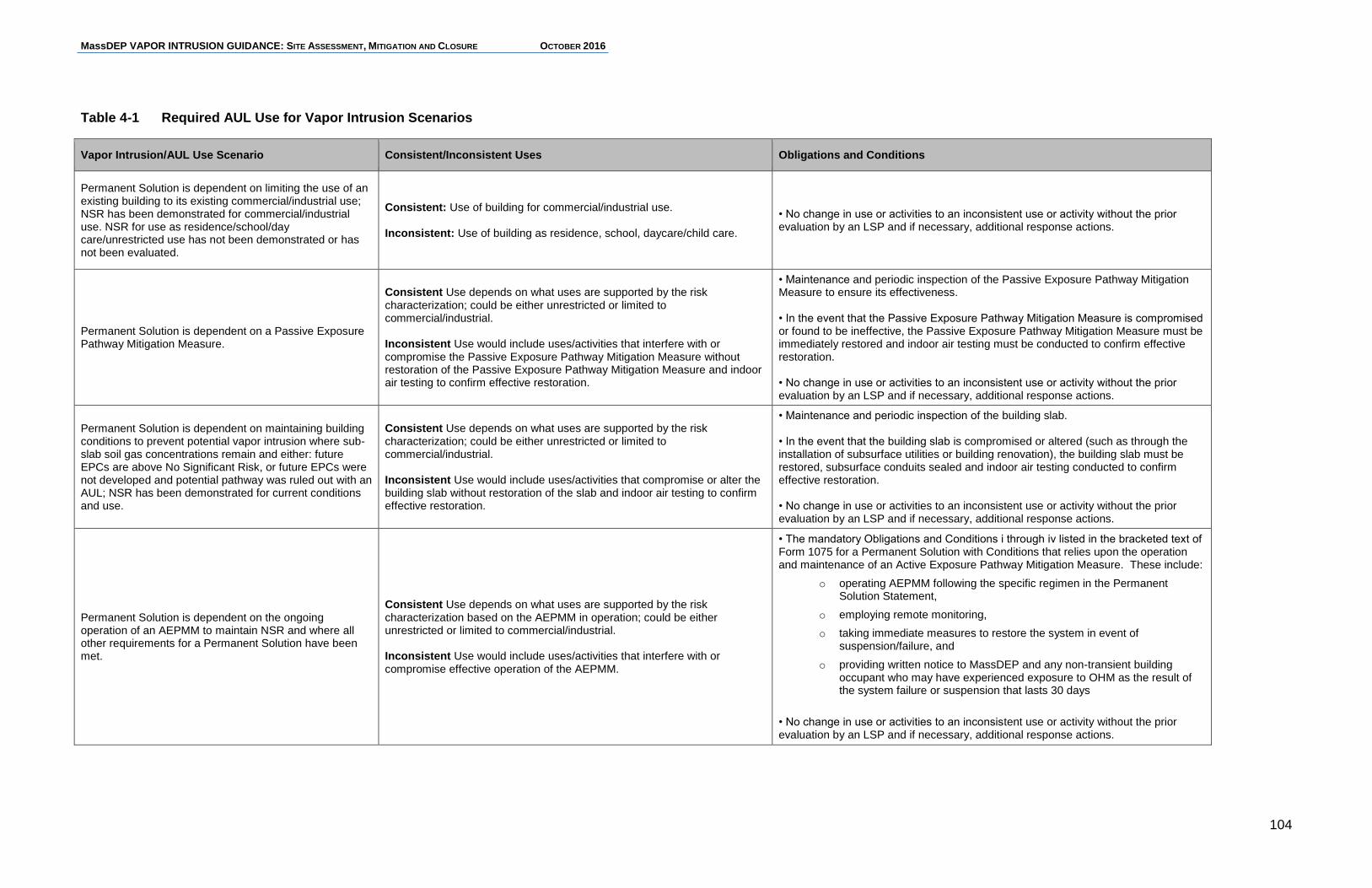
MassDEP VAPOR INTRUSION GUIDANCE: SITE ASSESSMENT, MITIGATION AND CLOSURE OCTOBER 2016
104
Table 4-1 Required AUL Use for Vapor Intrusion Scenarios
Vapor Intrusion/AUL Use Scenario Consistent/Inconsistent Uses Obligations and Conditions
Permanent Solution is dependent on limiting the use of an existing building to its existing commercial/industrial use; NSR has been demonstrated for commercial/industrial use. NSR for use as residence/school/day care/unrestricted use has not been demonstrated or has not been evaluated.
Consistent: Use of building for commercial/industrial use. Inconsistent: Use of building as residence, school, daycare/child care.
• No change in use or activities to an inconsistent use or activity without the prior evaluation by an LSP and if necessary, additional response actions.
Permanent Solution is dependent on a Passive Exposure Pathway Mitigation Measure.
Consistent Use depends on what uses are supported by the risk characterization; could be either unrestricted or limited to commercial/industrial. Inconsistent Use would include uses/activities that interfere with or compromise the Passive Exposure Pathway Mitigation Measure without restoration of the Passive Exposure Pathway Mitigation Measure and indoor air testing to confirm effective restoration.
• Maintenance and periodic inspection of the Passive Exposure Pathway Mitigation Measure to ensure its effectiveness. • In the event that the Passive Exposure Pathway Mitigation Measure is compromised or found to be ineffective, the Passive Exposure Pathway Mitigation Measure must be immediately restored and indoor air testing must be conducted to confirm effective restoration. • No change in use or activities to an inconsistent use or activity without the prior evaluation by an LSP and if necessary, additional response actions.
Permanent Solution is dependent on maintaining building conditions to prevent potential vapor intrusion where sub-slab soil gas concentrations remain and either: future EPCs are above No Significant Risk, or future EPCs were not developed and potential pathway was ruled out with an AUL; NSR has been demonstrated for current conditions and use.
Consistent Use depends on what uses are supported by the risk characterization; could be either unrestricted or limited to commercial/industrial. Inconsistent Use would include uses/activities that compromise or alter the building slab without restoration of the slab and indoor air testing to confirm effective restoration.
• Maintenance and periodic inspection of the building slab. • In the event that the building slab is compromised or altered (such as through the installation of subsurface utilities or building renovation), the building slab must be restored, subsurface conduits sealed and indoor air testing conducted to confirm effective restoration. • No change in use or activities to an inconsistent use or activity without the prior evaluation by an LSP and if necessary, additional response actions.
Permanent Solution is dependent on the ongoing operation of an AEPMM to maintain NSR and where all other requirements for a Permanent Solution have been met.
Consistent Use depends on what uses are supported by the risk characterization based on the AEPMM in operation; could be either unrestricted or limited to commercial/industrial. Inconsistent Use would include uses/activities that interfere with or compromise effective operation of the AEPMM.
• The mandatory Obligations and Conditions i through iv listed in the bracketed text of Form 1075 for a Permanent Solution with Conditions that relies upon the operation and maintenance of an Active Exposure Pathway Mitigation Measure. These include:
o operating AEPMM following the specific regimen in the Permanent Solution Statement,
o employing remote monitoring,
o taking immediate measures to restore the system in event of suspension/failure, and
o providing written notice to MassDEP and any non-transient building occupant who may have experienced exposure to OHM as the result of the system failure or suspension that lasts 30 days
• No change in use or activities to an inconsistent use or activity without the prior evaluation by an LSP and if necessary, additional response actions.
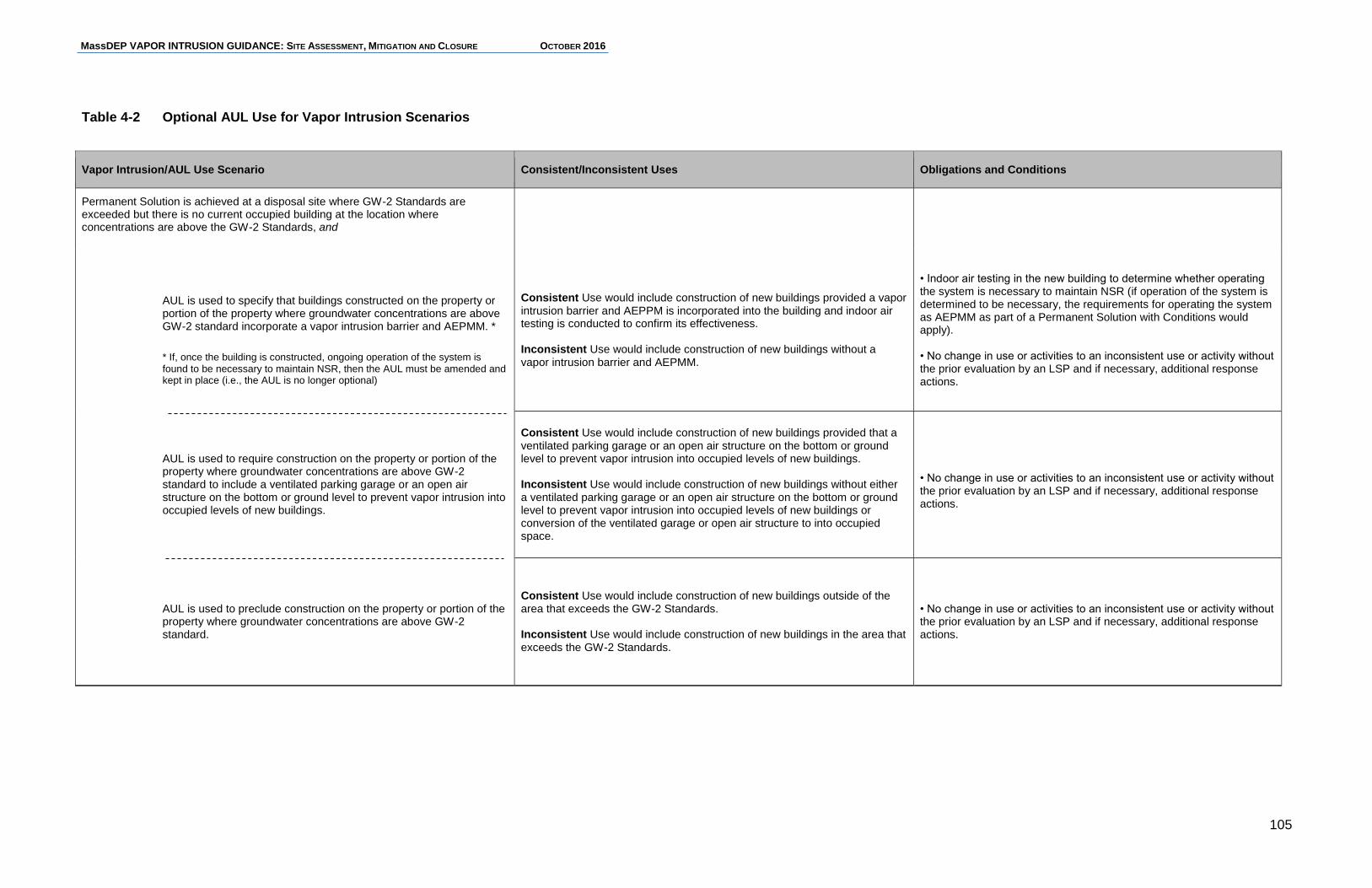
MassDEP VAPOR INTRUSION GUIDANCE: SITE ASSESSMENT, MITIGATION AND CLOSURE OCTOBER 2016
105
Table 4-2 Optional AUL Use for Vapor Intrusion Scenarios
Vapor Intrusion/AUL Use Scenario Consistent/Inconsistent Uses Obligations and Conditions
Permanent Solution is achieved at a disposal site where GW-2 Standards are exceeded but there is no current occupied building at the location where concentrations are above the GW-2 Standards, and
AUL is used to specify that buildings constructed on the property or portion of the property where groundwater concentrations are above GW-2 standard incorporate a vapor intrusion barrier and AEPMM. *
* If, once the building is constructed, ongoing operation of the system is found to be necessary to maintain NSR, then the AUL must be amended and kept in place (i.e., the AUL is no longer optional)
Consistent Use would include construction of new buildings provided a vapor intrusion barrier and AEPPM is incorporated into the building and indoor air testing is conducted to confirm its effectiveness. Inconsistent Use would include construction of new buildings without a vapor intrusion barrier and AEPMM.
• Indoor air testing in the new building to determine whether operating the system is necessary to maintain NSR (if operation of the system is determined to be necessary, the requirements for operating the system as AEPMM as part of a Permanent Solution with Conditions would apply). • No change in use or activities to an inconsistent use or activity without the prior evaluation by an LSP and if necessary, additional response actions.
AUL is used to require construction on the property or portion of the property where groundwater concentrations are above GW-2 standard to include a ventilated parking garage or an open air structure on the bottom or ground level to prevent vapor intrusion into occupied levels of new buildings.
Consistent Use would include construction of new buildings provided that a ventilated parking garage or an open air structure on the bottom or ground level to prevent vapor intrusion into occupied levels of new buildings. Inconsistent Use would include construction of new buildings without either a ventilated parking garage or an open air structure on the bottom or ground level to prevent vapor intrusion into occupied levels of new buildings or conversion of the ventilated garage or open air structure to into occupied space.
• No change in use or activities to an inconsistent use or activity without the prior evaluation by an LSP and if necessary, additional response actions.
AUL is used to preclude construction on the property or portion of the property where groundwater concentrations are above GW-2 standard.
Consistent Use would include construction of new buildings outside of the area that exceeds the GW-2 Standards. Inconsistent Use would include construction of new buildings in the area that exceeds the GW-2 Standards.
• No change in use or activities to an inconsistent use or activity without the prior evaluation by an LSP and if necessary, additional response actions.
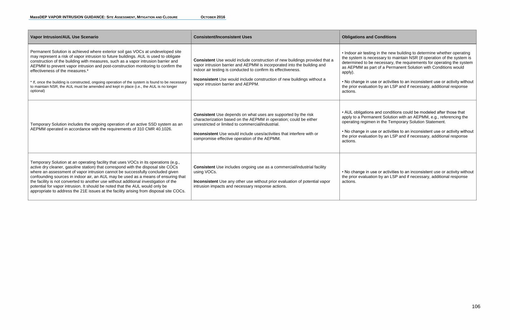
MassDEP VAPOR INTRUSION GUIDANCE: SITE ASSESSMENT, MITIGATION AND CLOSURE OCTOBER 2016
106
Vapor Intrusion/AUL Use Scenario Consistent/Inconsistent Uses Obligations and Conditions
Permanent Solution is achieved where exterior soil gas VOCs at undeveloped site may represent a risk of vapor intrusion to future buildings. AUL is used to obligate construction of the building with measures, such as a vapor intrusion barrier and AEPMM to prevent vapor intrusion and post-construction monitoring to confirm the effectiveness of the measures.*
* If, once the building is constructed, ongoing operation of the system is found to be necessary to maintain NSR, the AUL must be amended and kept in place (i.e., the AUL is no longer optional)
Consistent Use would include construction of new buildings provided that a vapor intrusion barrier and AEPMM is incorporated into the building and indoor air testing is conducted to confirm its effectiveness. Inconsistent Use would include construction of new buildings without a vapor intrusion barrier and AEPPM.
• Indoor air testing in the new building to determine whether operating the system is necessary to maintain NSR (if operation of the system is determined to be necessary, the requirements for operating the system as AEPMM as part of a Permanent Solution with Conditions would apply). • No change in use or activities to an inconsistent use or activity without the prior evaluation by an LSP and if necessary, additional response actions.
Temporary Solution includes the ongoing operation of an active SSD system as an AEPMM operated in accordance with the requirements of 310 CMR 40.1026.
Consistent Use depends on what uses are supported by the risk characterization based on the AEPMM in operation; could be either unrestricted or limited to commercial/industrial. Inconsistent Use would include uses/activities that interfere with or compromise effective operation of the AEPMM.
• AUL obligations and conditions could be modeled after those that apply to a Permanent Solution with an AEPMM, e.g., referencing the operating regimen in the Temporary Solution Statement. • No change in use or activities to an inconsistent use or activity without the prior evaluation by an LSP and if necessary, additional response actions.
Temporary Solution at an operating facility that uses VOCs in its operations (e.g., active dry cleaner, gasoline station) that correspond with the disposal site COCs where an assessment of vapor intrusion cannot be successfully concluded given confounding sources in indoor air, an AUL may be used as a means of ensuring that the facility is not converted to another use without additional investigation of the potential for vapor intrusion. It should be noted that the AUL would only be appropriate to address the 21E issues at the facility arising from disposal site COCs.
Consistent Use includes ongoing use as a commercial/industrial facility using VOCs. Inconsistent Use any other use without prior evaluation of potential vapor intrusion impacts and necessary response actions.
• No change in use or activities to an inconsistent use or activity without the prior evaluation by an LSP and if necessary, additional response actions.
MassDEP VAPOR INTRUSION GUIDANCE: SITE ASSESSMENT, MITIGATION AND CLOSURE OCTOBER 2016
107
4.7.2.4 Permanent Solutions with Conditions Based on Limitations on Activities, Conditions or Uses that do not Require/Include an AUL Permanent Solutions with Conditions that do not require an AUL, but are based upon limitations on activities, conditions or uses as set forth in 310 CMR 40.1013, do require documentation of the conditions as part of the Permanent Solution Statement and are subject to post-Permanent Solution requirements at 310 CMR 40.1067(5). Of these provisions, 310 CMR 40.1013(1)(d) is specifically applicable to disposal sites or portions of disposal sites where vapor intrusion is of potential concern. It applies to locations with VOCs in groundwater at concentration at or above the Groundwater Category GW-2 Standards where the average annual depth to groundwater of 15 feet or less and no occupied buildings exist (i.e., groundwater is not currently categorized as GW-2). As specified at 310 CMR 40.1056(2)(j)(4), where a Permanent Solution with Conditions applies to a location without existing occupied buildings, but a vapor intrusion concern for future construction exists based on the criteria above (groundwater concentrations ≥ GW-2 Standards with groundwater at an average annual depth ≤ 15 feet), the Permanent Solution Statement must document “information related to the presence of the groundwater contamination and the obligation to ensure any future construction at the disposal site does not result in OHM impacts to indoor air in newly constructed buildings or structures.” Information included in the Permanent Solution Statement should provide: an explanation of the nature of the disposal site conditions that are of concern for future construction which reflects the disposal site CSM, references to disposal site maps that delineate the areas of groundwater with VOC concentrations above the GW-2 Standards, the direction of groundwater flow, a statement that the property owner and persons constructing the building are obligated to ensure future development at the property does not result in the introduction of OHM from the disposal site into the indoor air of newly-constructed buildings and a reference to the requirements for remedial actions after a Permanent Solution has been submitted to MassDEP at 310 CMR 40.1067(5). Future construction of a building that results in exposure to OHM from the disposal site in indoor air in the new building is subject to notification requirements of 310 CMR 40.0300 and requires additional response actions to ensure that the requirements of a Permanent Solution are met for the change in conditions and potential exposure that may result from the building construction (310 CMR 40.1067(5)(e)). The Permanent Solution Statement, therefore, should reference measures that can be employed in the new construction to ensure that such construction does not result in vapor intrusion, including: construction of a ventilated parking garage/open air level below the occupied floors, or the installation of an AEPMM (or passive venting system that can be activated) that, post-construction, is demonstrated to protect against a complete vapor intrusion pathway. Section 4.8.3 provides more discussion of Post-Permanent Solution activities
MassDEP VAPOR INTRUSION GUIDANCE: SITE ASSESSMENT, MITIGATION AND CLOSURE OCTOBER 2016
108
and requirements at disposal sites where a Permanent Solution with Conditions is achieved and 310 CMR 40.1013(d) applies.
4.7.2.5 Voluntary Use of an AUL to Protect Future Buildings As discussed above, the use of an AUL is not required to condition future building construction at a disposal site where there is no current occupied building at the location where VOC concentrations in groundwater are above the GW-2 Standards. An AUL is also not required where residual VOCs in soil are below the Soil Category S-1 Standards. In both cases, an AUL may optionally be used to outline specific measures to be taken at the time of building construction or to limit construction at a property to locations outside of areas with VOC contamination. An AUL in such cases, while not required, has the benefit of providing future owners notice in the property deed as to the risks and obligations associated with future site development, including the requirement to notify and conduct response actions if construction results in OHM exposures in indoor air. An AUL is not required in the case of Temporary Solutions, but may be used in the same manner as an AUL that is used for Permanent Solutions, to provide notice of disposal site conditions, limit site use and activities, specify obligation and maintenance measures to maintain NSH, and document obligations related to property development. An AUL is also not required but may be used when an AEPMM is implemented as part of a Temporary Solution pursuant to 310 CMR 40.1026. AULs that are not required pursuant to 310 CMR 40.1012(2), but are implemented optionally as part of a Permanent Solution consistent with 310 CMR 40.1012(3), are considered Permanent Solution with Conditions, and the property owner is obligated to comply with the requirements of all AULs to maintain compliance with the MCP pursuant to 310 CMR 40.1070(2) or revise the Permanent or Temporary Solution to eliminate or modify the AUL. Voluntary AUL use examples are described in Table 4-2 above.
Example Vapor Intrusion Scenario 9 – Permanent Solution with Conditions, No AUL Required
A stable plume of VOC contaminated groundwater exceeds the GW-2 Standards in an area of the disposal site without existing buildings. If all other closure requirements are met, this site could qualify for a Permanent Solution with Conditions. No AUL is necessary, but the concern about potential vapor intrusion will be documented in the Permanent Solution with Conditions Statement to inform future land use decisions and guide any future construction at the property. The provisions of 310 CMR 40.1067(5) would be applicable to future development of the disposal site.
MassDEP VAPOR INTRUSION GUIDANCE: SITE ASSESSMENT, MITIGATION AND CLOSURE OCTOBER 2016
109
4.7.3 Implementing and Operating an AEPMM as part of a Permanent Solution with Conditions
The requirements for operation, monitoring and reporting for an AEPMM that is a necessary condition of a Permanent Solution with Conditions are outlined in 310 CMR 40.1025. An AEPMM may not be used as part of a Permanent Solution with Conditions if suspension or failure of the AEPMM (i.e., if the system was not operating or not operating effectively) for 60 consecutive days would result in a Receptor exposure to OHM that would pose an IH (310 CMR 40.1025(4)). See Section 4.7.3.1 for details on evaluating the risks associated with an AEPMM shutdowns to meet the requirement at 310 CMR 40.1025(4).
At sites where vapor intrusion has impacted the indoor air of residential, commercial or industrial buildings with TCE it may be difficult to achieve a Permanent Solution with Conditions that relies upon an AEPMM. Low TCE concentrations in indoor air could result in an IH in buildings with pregnant women or women who may become pregnant related to a risk of fetal heart malformation during the first eight weeks of pregnancy. This Exposure Period is, by definition, less than 60 days and therefore, the requirement at 310 CMR 40.1025(4) would not be met. However, in cases with a robust data set and CSM demonstrating that the EPC for TCE in the absence of an operating AEPMM is less than the IH concentration for either a residential setting or commercial/industrial setting the requirement at 310 CMR 40.1025(4) could be met.
Another threshold requirement for use of AEPMMs as part of a Permanent Solution with Conditions is that the property owner, at the time of implementation, provide a certification that financial resources have been made available for the immediate repair and/or replacement of AEPMM components if the AEPMM experiences failure and implement an AUL that includes the obligation to operate and maintain the system and repair or replace it if necessary to continue its operation. The discussion below outlines the steps that are necessary before and after submitting a Permanent Solution Statement with Conditions where the operation of an AEPMM is a required condition of such Permanent Solution. Before submitting a Permanent Solution Statement for a Permanent Solution with Conditions that relies on operation of an AEPMM:
1. demonstrate that the AEPMM eliminates exposure to OHM to the extent feasible and at a minimum, ensures that NSR is achieved and maintained for the Receptor(s) of concern. The effectiveness of the AEPMM shall be demonstrated through monitoring of EPCs under normal operating conditions and over a period of time sufficient to account for temporal variability;
2. establish an AEPMM operating regimen that ensures, at a minimum, NSR is maintained for the Receptor(s) of concern under normal operating conditions (310 CMR 40.1025(3)(b));
MassDEP VAPOR INTRUSION GUIDANCE: SITE ASSESSMENT, MITIGATION AND CLOSURE OCTOBER 2016
110
3. equip the AEPMM with remote monitoring (a.k.a., telemetry) technology that will alert the owner and operator of the building protected by the AEPMM and MassDEP immediately upon failure of the system (such as loss of power, mechanical failure or other significant disruption of the effectiveness of the system)(310 CMR 40.1025(3)(d));
4. register the remote monitoring technology with MassDEP (as described in Section 3.6.5) to confirm its ability to provide required alerts to MassDEP;
5. document in the Permanent Solution Statement:
a. the operating regimen of the AEPMM (as established in Step 2 above) that includes the parameters for operating the AEPMM and the methods and frequency for monitoring necessary to ensure consistent operation within the required parameters; and
b. the longest duration of a shutdown that would be consistent with (1) a level of exposure that does not pose an IH, and (2) the level of exposure that poses No Significant Risk (see Section 4.7.3.1);
6. demonstrate and document in the Permanent Solution Statement that all other requirements of a Permanent Solution are met, (including, but not limited to, delineation of OHM at the disposal site and assessment of Sources of OHM, risk characterization, Source Elimination and Control, Migration Control, NAPL removal to the extent feasible, disposal site CSM, and Representativeness Evaluation and Data Usability Assessment);
7. include a certification by the owner of the property where the AEPMM is located in the Permanent Solution Statement that the financial resources for the immediate repair and/or replacement of AEPMM or AEPMM components have been made available (310 CMR 40.1025(5)); and
8. record an AUL that includes the required Obligations and Conditions for the operation of an AEPMM in Form 1075 and references the operating regimen in the Permanent Solution Statement (310 CMR 40.1025(3)(a).
Once a Permanent Solution with Conditions Statement is submitted, Status and Remedial Monitoring Reports for the operation of the AEPMM are no longer required. After submitting a Permanent Solution Statement for a Permanent Solution with Conditions that relies on operation of an AEPMM:
As a condition of maintaining such a Permanent Solution with Conditions, continued operation of the AEPMM according to the AUL and the operating regimen as documented in the Permanent Solution Statement is required. If the property where the AEPMM is located is sold, the obligation for maintaining the AEPMM transfers with the property to the subsequent property owner as do all requirements specified in the AUL. Any subsequent property owner is required to ensure the system’s ongoing operation according to the conditions of the AUL and Permanent Solution Statement unless and until it is demonstrated that the AEPMM is not necessary to maintain NSR, the AUL is terminated, and a revised
MassDEP VAPOR INTRUSION GUIDANCE: SITE ASSESSMENT, MITIGATION AND CLOSURE OCTOBER 2016
111
Permanent Solution is submitted to the Department that documents the change in conditions associated with the revised Permanent Solution;
Following suspension or failure of an AEPMM, the owner of a property with an AEPMM must undertake immediate steps to return the AEPMM to full operating condition. If the suspension or failure of the system lasts 30 consecutive days, the property owner must provide a written notice to both the MassDEP and any non-transient occupants of the affected building. This notice must include the reason for the failure, the steps being taken to resume operation and the expected timeframe for resuming operation (310 CMR 40.1025(6)). Note, this requirement is in addition to maintaining a remote monitoring technology as part of the AEPMM that alerts the owner and operator of the building protected by the AEPMM and MassDEP immediately upon failure of the system;
A property owner with an AEPMM must annually certify, in response to receipt of a form sent to the current property owner by MassDEP, that he/she/the ownership entity:
a. is aware of the obligation to operate, maintain and repair the AEPMM;
b. will allow MassDEP to inspect the AEPMM upon reasonable notice;
c. has financial resources available for immediate repair and/or replacement of AEPMM components; and
d. the AEPMM is operating according to the operating regimen referenced in the AUL and documented in the Permanent Solution Statement.
4.7.3.1 Determining the Effects of AEPMM Shutdowns Since an AEPMM reduces or eliminates exposure to VOCs in indoor air only as long as the AEPMM remains operational, it is important that the potential consequences of an AEPMM failure are known and effectively documented. To that end, the MCP has two requirements that address the longer-term shutdown of an AEPMM:
An AEPMM may not be used as part of a Permanent Solution with Conditions if the failure of the measure lasting 60 consecutive days would result in conditions that would pose an IH (310 CMR 40.1025(4)).
The longest duration of a shutdown that would be consistent with a level of exposure that does not pose an IH and a level of exposure consistent with NSR must be documented where AEPMMs are used as part of a Permanent Solution or Temporary Solution/Remedy Operation Status (310 CMR 40.1025(3)(e) and 310 CMR 40.1026(3)(e), respectively).
Evaluations to meet these requirements should be based on representative indoor air EPCs in the building when the AEPMM is not in operation assuming current use conditions using either indoor air concentrations before activation of the AEPMM (worst case) or more recent data collected when the AEPMM was not in operation if such data can be collected without triggering an IH. In most cases the Department does not recommend shutting down an AEPMM installed to address an IH to obtain post-
MassDEP VAPOR INTRUSION GUIDANCE: SITE ASSESSMENT, MITIGATION AND CLOSURE OCTOBER 2016
112
installation indoor air EPCs without some indication that VOCs concentrations in the subsurface have significantly decreased (e.g., based on VOC concentrations measured in vent since system start-up) or sensitive receptors are protected in some other manner such as temporary relocation during the shutdown/indoor air testing.
To demonstrate that an AEPMM failure lasting 60 consecutive days would not result in an IH as a requirement of using an AEPMM as part of a Permanent Solution with Conditions (310 CMR 40.1025(4)), MassDEP recommends the following simplified approaches (alternative site-specific approaches may be considered):
For potential non-cancer effects, those OHM associated with adverse health impacts following acute exposures (60 days or fewer) should be the focus of the evaluation. The list of such chemicals is limited. MassDEP's Chemical Research & Standards website identifies chemicals for which short-term exposures at (http://www.mass.gov/eea/agencies/massdep/toxics/sources/chemical-research-and-standards.html).
For potential carcinogenic effects, IH are based on a minimum exposure duration of 5 years. For the purposes of 310 CMR 40.1025(4), it may be assumed that the concentration that would pose an IH for a 60-day exposure is equal to thirty times7 the concentration that would pose an IH for a 5-year exposure. For example, using the MassDEP’s Risk Assessment ShortForm for the evaluation of IH from inhalation of indoor air8, an EPC for tetrachloroethylene of 47µg/m3 could pose an IH for a 5-year exposure period. Therefore using the 30-fold factor described above, a site with tetrachloroethylene EPCs (absent mitigation) up to 1,410 µg/m3 (30 x 47 µg/m3) might be eligible for a Permanent Solution pursuant to 310 CMR 40.1025(4).
To determine the longest duration of a shutdown that would be consistent with a level of exposure that (a) does not pose an IH and (b) is consistent with NSR (310 CMR 40.1025(3)(e) and 310 CMR 40.1026(e), the Department recommends the following simplified approaches (alternative site-specific approaches may be considered):
For potential non-cancer effects, the Averaging Period used to evaluate potential risk is typically the same as the Exposure Period, and therefore the estimated risk posed by a given acute, subchronic or chronic exposure is not cumulative over time. For the purposes of 310 CMR 40.1025(3)(e) and 40.1026(3)(e), MassDEP recommends:
o The use of 60 days as a shutdown duration that does not pose an IH considering only potential acute non-cancer effects.
o The use of 1 year as a shutdown duration that does not pose an IH considering only potential subchronic non-cancer effects.
7 The “thirty times” factor accounts for the fact that the exposure period of 60 days (2 months) is
approximately 30 times shorter than the typical 5 year (60 months) exposure. 8 Spreadsheet: sf12raih.xlsx, available at:
http://www.mass.gov/eea/agencies/massdep/toxics/sources/riskasmt-htm.html#7
MassDEP VAPOR INTRUSION GUIDANCE: SITE ASSESSMENT, MITIGATION AND CLOSURE OCTOBER 2016
113
o The use of 7 years as a shutdown duration that poses No Significant Risk considering only potential chronic non-cancer effects.
For potential carcinogenic effects, the Averaging Period used to evaluate potential risk is typically a lifetime, while the Exposure Period depends upon site-specific conditions and the nature or the risk under evaluation (e.g., 5 years for Imminent Hazards, 30 years for chronic exposure). Therefore the standard risk assessment equations9 may be re-arranged to solve for the Exposure Period (EP) factor which would be the “longest duration of shutdown” meeting specific risk criteria:
Where:
ELCR = The target cancer risk limit, one-in-one hundred thousand (1E-05).
[OHM]air = Exposure point concentration in the air at the Exposure Point during the period of exposure (dimensions: mass/volume; typical units: μg/m
3).
URinhalation = The Inhalation Unit Risk value (risk per μg/m3)
EF = Number of exposure events (frequency) during the exposure period divided by the number of days in the exposure period (dimensions: events/time; typical units: events/day)
ED = Duration of each exposure event (dimensions: time/event; typical units: hours/event)
EP = Duration of the exposure period (dimensions: time; typical units: years)
AP = Averaging Period (dimension: time; typical units: years)
C = Appropriate units conversion factor(s) (e.g., 10-6 kg/mg, 1 week/7 days)
Alternatively, the MassDEP ShortForms for Human Health Risk Assessment may be used to quickly estimate the “longest duration of a shutdown”. For example, at a residential location with tetrachloroethylene concentrations in indoor air of 150 µg/m3, the Resident – Indoor Air Imminent Hazard ShortForm (sf12raih.xlsx) indicates a potential Excess Lifetime Cancer Risk of 3.2E-05, which is 3.2 times the IH level of 1E-05. Since the IH risk calculation is based on a 5-year exposure, the longest shutdown duration that would not pose an IH due to potential cancer risk is:
9 See for example the equations described in Chapter 7 of the Guidance for Disposal Site Risk
Characterization (MassDEP, 1995) at http://www.mass.gov/eea/agencies/massdep/toxics/sources/riskasmt-htm.html#4
C * EP * ED * EF * ][OHMUR
APELCR = EP
airinhalation

MassDEP VAPOR INTRUSION GUIDANCE: SITE ASSESSMENT, MITIGATION AND CLOSURE OCTOBER 2016
114
4.7.4 Temporary Solutions At disposal sites with vapor intrusion pathways, a Temporary Solution can often be achieved where implementation of a Permanent Solution is not currently feasible, but where a condition of NSH has been met and is being maintained. Temporary Solutions must be supported by a Phase II assessment of the nature and extent of contamination and risk characterization for the entire disposal site and a Phase III feasibility evaluation that supports the implementation of Temporary Solution rather than a Permanent Solution.
Examples of conditions that can exist at disposal sites where vapor intrusion is a concern which would not meet the requirements of a Permanent Solution but could qualify for a Temporary Solution include:
where OHM plumes in groundwater or vapor phase cannot be demonstrated to be stable or contracting, but are controlled;
where Non-stable NAPL has not been eliminated, but is controlled to the extent feasible;
where the Active Operation and Maintenance of an Active Remedial System (e.g., a soil vapor extraction system) or Active Remedial Monitoring Program is ongoing to maintain NSH and/or treat/control Sources of OHM or control plume migration; and/or
310 CMR 40.1057 outlines the requirements for Temporary Solution Statements. These requirements include providing documentation of any operation, maintenance, and/or monitoring that will be required to confirm and/or maintain those conditions at the disposal site on which the Temporary Solution is based. Where an AEPMM is being operated as part of maintaining a Temporary Solution, additional requirements apply, as discussed in Section 4.7.4.1 below. Use of an AUL is not required as part of a Temporary Solution. Pursuant to 310 CMR 40.1012(3)(g), property owners may elect to implement an AUL to provide notice of the presence and nature disposal site contamination and/or to record obligations and conditions for maintaining remedial systems, barriers and other mitigation measures. Where an optional AUL is used, property owners are required to comply with its terms in order to maintain compliance with the MCP pursuant to 310 CMR 40.1070(2). Table 4-2 includes examples of AULs used for Temporary Solutions. 310 CMR 40.0897 outlines Post-Temporary Solution operation, maintenance and/or monitoring activities and documentation. The scope of these activities will be based on the remedial action being undertaken. Post-Temporary Solution operation, maintenance and/or monitoring activities must be documented in Post-Temporary Solution Status Reports, as described in 310 CMR 40.0898(2). At a minimum, a Post-Temporary Solution Status Report must be submitted to the Department at 6-month intervals. For disposal sites where Active Operation and Maintenance of a remedial action is being
MassDEP VAPOR INTRUSION GUIDANCE: SITE ASSESSMENT, MITIGATION AND CLOSURE OCTOBER 2016
115
conducted, RMRs must be submitted with the first Post-Temporary Solution Status Report and every six months thereafter, in accordance with 310 CMR 40.0898(3). 4.7.4.1 Implementing and Operating an AEPMM as part of a Temporary Solution
or Remedy Operation Status The requirements for operation, monitoring and reporting for an AEPMM as part of a Temporary Solution or as part of measures conducted under ROS are specified at 310 CMR 40.1026. These requirements are similar to those for an AEPMM in a Permanent Solution with Conditions outlined earlier. However, for AEPMMs operated as part of a Temporary Solution or ROS:
an AUL is not required;
there is no restriction on the use of the system to address an indoor air concentration that would pose an IH within 60 days of a system failure;
there is no requirement to certify that financial resources for system repair or replacement are available at the time the Temporary Solution or ROS is submitted; and
there is no annual certification process. Another important difference is that for AEPMMs operated as part of Temporary Solutions or ROS, RMRs and Status Reports are still required; RMRs and Status Reports are not required after submitting a Permanent Solution Statement. 4.8 Post-Closure Requirements and Considerations for Disposal Sites with
Vapor Intrusion Concerns At disposal sites with a Permanent Solution, there is an obligation to maintain the Permanent Solution and abide by the terms of any AUL or conditions that have been implemented in support of the Permanent Solution. There are also requirements that apply to evaluating changes in site activities and uses and conditions that may result in exposures above a level of NSR as well as conducting remedial actions at the disposal site after the Permanent Solution has been submitted. This section outlines the requirements and considerations for activities occurring at disposal sites where the conditions related to an ongoing or potential vapor intrusion pathway apply to maintaining the Permanent Solution. 4.8.1 Voluntary Continuation of Vapor Intrusion Mitigation In cases where a Permanent Solution has been achieved that is not dependent on the ongoing operation of an AEPMM installed as an MCP response action, MassDEP recognizes that a building owner or operator may nevertheless want to continue operating the system to reduce or protect against exposure to remaining low concentrations of contamination and/or for the benefit of mitigating radon, a concern
MassDEP VAPOR INTRUSION GUIDANCE: SITE ASSESSMENT, MITIGATION AND CLOSURE OCTOBER 2016
116
that is not regulated under the MCP10. Without the ongoing MCP oversight and submittal costs, the electricity and maintenance costs for AEPMMs are typically very affordable. Such ongoing operation would not be viewed as a mandatory condition of the Permanent Solution. Where ongoing voluntary operation of the system is anticipated at the time that the Permanent Solution is submitted to the Department, it is recommended that Permanent Solution Statement clarify the voluntary nature of its use with respect to MCP compliance. 4.8.2 Post-Closure Work at a Disposal Site with a Permanent Solution with
Conditions and an AUL At disposal sites where a Permanent Solution with Conditions has been achieved that includes an AUL, maintaining a Permanent Solution requires ensuring a condition of NSR and abiding by the terms of the AUL, including obligations and conditions requiring the inspection and maintenance of barriers or systems to prevent or mitigate vapor intrusion. In the event that inspections of the systems or barriers indicate that repairs or modifications are needed, remedial actions must be taken. Where action is required to repair or modify an existing barrier or system or otherwise conduct remedial actions at a disposal site within an AUL area, that work must be performed pursuant to 310 CMR 40.1067(4). These provisions allow for work involving limited soil excavation (excavation of 100 cubic yards or less of soil contaminated with oil or waste oil, or 20 cubic yards or less of soil contaminated with hazardous material) to be conducted without the need to notify the Department or to submit a plan. Otherwise, remedial actions in the AUL area require a RAM Plan, or if the work exceeds the scope of a RAM (as described at 310 CMR 40.0442), a Phase IV Remedy Implementation Plan. These plans must meet the RAM (or Phase IV RIP) provisions, providing the objective of the work, description of assessment and remedial activities, schedule, and plans/sketches of any installations. RAM Status Reports are also required if the work is not completed within 120 days of submitting the RAM Plan. Completion of the work must be documented with a RAM Completion Statement. If it is determined that new conditions are required for maintaining NSR that are beyond what is provided in the AUL (e.g., a passive venting system must now be operated as an AEPMM), then an AUL Amendment is necessary to document that change in terms. Note, for Permanent Solutions with Conditions that rely on AEPMMs, changes to the operating regimen which are otherwise not specified in the AUL may be made by revising that information in the Permanent Solution Statement. Those changes should also be documented in the RAM Completion Statement. Post-closure remedial actions at disposal sites with a Permanent Solution may also be performed with the objective of remediating the disposal site further and removing an AUL (e.g., achieving NSR that is not conditioned on an AUL). Activities limited to
10
If there is a complete vapor intrusion pathway that is allowing site-related contamination to enter a building, it is reasonable to assume that the natural contaminant radon, if present in the subsurface, is also entering the building. See EPA’s A Citizen’s Guide to Radon at http://www.epa.gov/radon/pubs/citguide.html.
MassDEP VAPOR INTRUSION GUIDANCE: SITE ASSESSMENT, MITIGATION AND CLOSURE OCTOBER 2016
117
assessment (e.g., sampling indoor air with systems not operating and/or sampling sub-slab soil gas and groundwater) to demonstrate that an AUL and its obligations and conditions are no longer necessary do not have to be conducted as a RAM, but the results of such assessments would be documented in a revised Permanent Solution Statement. See Section 3.7 for a discussion of sampling to demonstrate that a mitigation system in no longer needed. 4.8.3 Post-Closure Work at a Disposal Site with a Permanent Solution with
Conditions and No AUL At disposal sites where a Permanent Solution with Conditions has been achieved without an AUL, but residual contamination in groundwater is above the GW-2 standards (310 CMR 40.1013(1)(d)), maintaining the Permanent Solution requires ensuring that future building construction does not create a vapor intrusion pathway. Post-closure remedial activities at disposal sites with a Permanent Solution with Conditions but no AUL must be conducted pursuant to 310 CMR 40.1067(5). As specified in 310 CMR 40.1067(5)(e), in the event that a building is constructed and indoor air is found to be impacted by VOCs from the disposal site, notification to MassDEP is required pursuant to 310 CMR 40.0300. 4.8.4 New Buildings Constructed at a Disposal Site Where the Potential for the
Vapor Intrusion Pathway Exists To avoid creating new exposures, new construction should include measures to eliminate or minimize the possibility of vapor intrusion. The measures taken should be commensurate with the disposal site CSM and the concentration of contamination remaining at the site. It is recommended, therefore, if many years have passed since a Permanent Solution was achieved, that groundwater be sampled to evaluate current conditions, including whether the potential for vapor intrusion remains a concern. Some measures that minimize the possibility of vapor intrusion have become standard construction practices, such as the use of vapor barriers or passive radon systems. A building’s design may include features which preclude or limit the transfer of contaminated vapor to an occupied space, such as the use of a garage at or below ground level. Standard construction practices including “soil gas safe” building design components do not need to be undertaken following MCP requirements, provided that they do not require the management of Remediation Waste during construction or any ongoing operation, maintenance, or monitoring in the completed building. Operation of garage ventilation systems that are required by building code would have no further MCP requirements. It is recommended that sampling of indoor air be conducted once construction of a new building has been completed but before the building is occupied. This will avoid, in the event that vapor intrusion is found to be occurring, the need to notify for IH and Conditions of SRM (that are triggered by current exposures to current occupants) and will allow the work to mitigate the pathway to be performed as a RAM (pursuant to 310

MassDEP VAPOR INTRUSION GUIDANCE: SITE ASSESSMENT, MITIGATION AND CLOSURE OCTOBER 2016
118
CMR 40.1067(4) or (5)). Where the new building is determined to rely on a Passive or Active Exposure Pathway Mitigation Measure to ensure maintenance of a level of NSR, an AUL must be implemented to document that maintenance of those measures is a requirement of maintaining the Permanent Solution and the Permanent Solution Statement must be revised to reflect the applicable conditions.
MassDEP VAPOR INTRUSION GUIDANCE: SITE ASSESSMENT, MITIGATION AND CLOSURE OCTOBER 2016
119
5. COMMUNICATION AND PUBLIC INVOLVEMENT
5.1 Introduction
The purpose of public involvement activities under the MCP is to inform the public about potential risks posed by the disposal site, present information about the status of response actions, and provide opportunities to obtain additional information. Public involvement can be particularly important at sites where vapor intrusion issues exist because vapor intrusion is not well understood by many members of the public, and affected structures can include residences, schools and workplaces. Residents and users of affected buildings will naturally have concerns about potential risks to their health and questions about assessment and mitigation activities. MassDEP’s experience confirms that providing information to the public in a timely and straight-forward manner is a key element of a successful project and building trust with the public. Delayed communication with the community may result in an erosion of trust. Information that is respectful of and understandable by non-technical audiences and anticipates likely questions can be effective in addressing concerns and fostering cooperation during the response action process.
The vapor intrusion pathway can be a difficult and sensitive environmental issue to communicate to the public. Complicating aspects of vapor intrusion include: (1) the unavoidable nature of indoor air inhalation exposure while vapor intrusion is occurring; (2) logistical issues surrounding sub-slab soil gas and indoor air sampling in buildings; and (3) the potential for detecting indoor air contamination unrelated to the environmental release under investigation (e.g., VOCs from smoking, household products or hobby chemicals). These issues are often challenging to explain to building inhabitants and users.
In light of these challenges, MassDEP encourages early, clear and frequent communication with property owners and other concerned and potentially affected individuals about vapor intrusion issues. Communication should be inclusive and written materials easily understandable, with sensitivity toward possible language and cultural barriers. This section identifies:
MCP public involvement requirements outlined in 310 CMR 40.1400 related to vapor intrusion investigation and mitigation (Sections 5.2, 5.3, and 5.4); and
Optional opportunities and tools that may be useful in enhancing communication with the public on vapor intrusion issues (Sections 5.5 and 5.6).
The risk communication and public involvement requirements in the MCP are the responsibility of the PRP. In practice, MassDEP and local Health Departments often play a role as well. In some cases, members of the public contact MassDEP or local officials to discuss their concerns with a site and the status of response actions. MassDEP may also be involved in approving response actions. MassDEP and local
MassDEP VAPOR INTRUSION GUIDANCE: SITE ASSESSMENT, MITIGATION AND CLOSURE OCTOBER 2016
120
officials may participate in public meetings. MassDEP staff is available to discuss vapor intrusion sites with concerned individuals and to help with drafting and/or translation of site-specific fact sheets.
5.2 Requirements for Notification of Property Owners and Affected Individuals
The MCP contains several specific requirements for notifying property owners who are not otherwise conducting response actions, and for notifying Affected Individuals at a site. Property owners include public entities (e.g., municipalities, federal and state agencies) in the case of publicly owned property. Standardized forms (available at http://www.mass.gov/dep/cleanup/approvals/trforms.htm#trans) have been developed and must be used for providing these notifications. These requirements and related forms are described below.
5.2.1 Notice of Environmental Sampling (Form BWSC123)
Providing property owners with a written notification of sampling and the analytical results once they become available is required any time environmental samples are collected as part of response actions under the MCP at a property on behalf of someone other than the owner of the property (310 CMR 40.1403(10)). This written notice, titled Notice of Environmental Sampling, is made using Form BWSC123. The purpose of this notice is to: inform the property owner that he/she will be receiving the results of the sampling and analysis, and to ensure that such results are subsequently provided to the property owner within a specific timeframe from the date the laboratory issues the analytical data. These requirements apply to indoor air sampling, as well as other environmental media (sub-slab soil gas, groundwater, soil, etc.). 310 CMR 40.1403(10) specifies additional details about the required timing of the Notice of Environmental Sampling and documentation. Analytical results provided to the property owner must include the number and type of samples (i.e. environmental medium sampled and analyzed), the chemicals identified, and the measured concentrations of the chemicals identified. Information on optional communication related to environmental sampling results is provided in Section 5.6.
5.2.2 Notice Related to Immediate Response Actions (Form BWSC124)
Conducting a remedial action as part of an IRA to address an IH or CEP requires the person conducting the IRA to provide notification to owners, operators and other persons that may experience “significant health or safety impacts (i.e. Affected Individuals as defined in 310 CMR 40.0006(12))” from the disposal site subject to the IRA (310 CMR 40.1403(11). Notification is required within 72 hours of commencing the remedial action. The initial notification may be made verbally, but must be followed by a written notice. The written notice, titled Informational Notice about Immediate Response Actions, is made using Form BWSC124. The purpose of this notice is to inform its
MassDEP VAPOR INTRUSION GUIDANCE: SITE ASSESSMENT, MITIGATION AND CLOSURE OCTOBER 2016
121
recipients of the scope and nature of the remedial actions given that such activities may raise logistical questions and/or health concerns. This notice is not required in cases where the IRA is limited to assessment only. For vapor intrusion sites, “Affected Individuals” who may experience health or safety impacts can include residents of affected residential buildings and workers in commercial or industrial space where a remedial action is being. In addition to notifying Affected Individuals, 310 CMR 40.1403(11)(d) requires, in the case of multi-unit or industrial or commercial buildings, that the person conducting the IRA request that the owners and/or operators of the buildings post the notice where it will be visible to individuals who are routinely present in such building(s). Once the IRA is completed, written notice must again be provided using Form BWSC124 along with a copy of the IRA Completion Statement to the same Affected Individuals who received earlier notice of the remedial action. A copy of this notice must also be submitted to the Department with the IRA Completion Statement. Notice Related to Immediate Response Actions Where TCE in Indoor Air poses an Imminent Hazard – Special Case Because of the specific nature of the potential short-term exposure risk of heart malformations in developing fetuses posed by exposure to trichloroethylene, MassDEP has developed detailed fact sheets to use as part of the Notice to inform residents and workers where TCE is measured in indoor air at IH levels. These fact sheets are titled:
“Important Information about Trichloroethylene (TCE) in Residential Indoor Air” (http://www.mass.gov/eea/docs/dep/cleanup/laws/tceresin.pdf); and
“Important Information on Trichloroethylene (TCE) in Workplace Indoor Air” (http://www.mass.gov/eea/docs/dep/cleanup/laws/tcewkin.pdf).
These facts sheets are appropriate to provide along with the written Notice using Form BWSC124 required by 310 CMR 40.1403(11).
5.2.3 Notification of Owners of Property within the Boundaries of a Disposal Site (Form BWSC122)
310 CMR 40.1406 outlines requirements for notification to property owners with property located wholly or partially within the disposal site boundaries. These requirements apply to notifying owners of properties with buildings where vapor intrusion has been identified. This notification is made using Form BWSC122, titled Informational Notice to Property Owners. The person conducting response actions is required to provide this notification to all applicable property owners at two points in the response action process – at the time the Phase II Report is submitted to MassDEP, and at the time the Permanent or
MassDEP VAPOR INTRUSION GUIDANCE: SITE ASSESSMENT, MITIGATION AND CLOSURE OCTOBER 2016
122
Temporary Solution Statement is submitted. In the event that additional investigation later determines that a property is in fact not within the boundaries of the disposal site, subsequent notice must be given to provide the updated information to the property owner. 310 CMR 40.1406(4) provides an alternative means of providing notice to property owners within the boundaries of disposal site when the number of affected properties exceeds 50. In such cases, MassDEP approval of the alternative approach is required and the local Board of Health must be informed prior to providing the notice. An example of alternative approach is publishing a public notice in the local newspaper.
5.3 General Public Notification and Involvement
The MCP’s general public notice (i.e., newspaper notices) requirements and public involvement opportunities apply to vapor intrusion sites. They serve to inform the public as well as local officials about risks posed by a disposal site, the status of response actions, and opportunities for public involvement that are provided by the regulations. General public involvement information is summarized in a MassDEP fact sheet available at http://www.mass.gov/eea/docs/dep/cleanup/factpi2.pdf.
5.3.1 Public Involvement Opportunities During Preliminary Response Actions
MassDEP’s fact sheet, “Opportunities for Public Involvement in Preliminary Response Actions,” available at http://www.mass.gov/eea/agencies/massdep/cleanup/regulations/mcp-public-involvement-in-preliminary-response-actions.html, outlines the process specified at 310 CMR 40.1403(9) that the public and local officials may use to become involved with disposal sites in their community during Preliminary Response Actions (IRAs and RAMs). Residents and local officials may send a written request for information to the party conducting an IRA or RAM, and that party in turn is required to respond to the request and provide “appropriate opportunities for public comment.” The regulations provide some flexibility as to what activities are identified as public comment opportunities, but indicate that activities may include a public meeting or opportunity for the public to submit written comments.
5.3.2 Public Involvement Plan (PIP) Designation for Disposal Sites
Once a disposal site is tier classified, 310 CMR 40.1404 allows the site to be designated a Public Involvement Plan site or “PIP site” through the filing of a petition signed by ten or more residents or by request of local officials. PIP site designation requires that additional public involvement activities be conducted, including the development of a Public Involvement Plan, which must be implemented by the party conducting response actions. These additional activities include holding a public meeting and providing for public comment on response action submittals. The designation of a disposal site as a PIP site provides an opportunity for community residents to ask questions about disposal sites and receive documented responses. MassDEP's fact sheet, “Tips on PIPs: Understanding and Using the Public Involvement Processes” at
MassDEP VAPOR INTRUSION GUIDANCE: SITE ASSESSMENT, MITIGATION AND CLOSURE OCTOBER 2016
123
http://www.mass.gov/eea/agencies/massdep/cleanup/sites/understanding-and-using-the-public-involvement-processes.html, provides information on the PIP site process.
5.4 Notice to Local Officials
The MCP requires that the Chief Municipal Officer and Board of Health be informed of specific IRA activities and milestones at disposal sites in their community, including:
implementation of an IRA to address an IH or CEP (310 CMR 40.1403(3)(b)); and
submittal of a IRA Completion Statement for an IH (310 CMR 40.1403(3)(c)).
Other activities and events requiring notification of the local officials that are or may be relevant to vapor intrusion sites include:
sampling of indoor air or surficial soils at residential properties at, adjacent to, or downgradient from any contamination or suspected contamination (310 CMR 40.1403(3)(a));
field work using respirators or Level A, B or C protective clothing (310 CMR 40.1403(3)(a));
Implementation of Release Abatement Measures;
Availability of Phase Reports, Phase III Remedial Action Plans, Phase IV Remedy Implementation Plans, Permanent or Temporary Solution and Downgradient Property Status Opinions; and
Recording/registering, amendment, release or termination of a Notice of an AUL.
Recommendations on optional communication and coordination with local officials are provided in Section 5.5. 5.5 Coordination with Local Officials When addressing vapor intrusion sites, situations may arise that would benefit from communication and coordination with local Boards of Health and Health Departments beyond the required notification of local officials. Situations of particular concern are 2-hour notification conditions, and locations with sensitive receptors or high visibility (residences, schools, daycare centers, hospitals, and public buildings such as community centers and libraries). Local officials may be interested in providing assistance with risk communication. They would be aware of any language barriers and the need for translation services, and may be able to suggest local contacts and appropriate media for risk communication efforts (appropriate local newspapers/media and locations for information repositories). The degree of involvement of local officials will vary by town and by situation. Boards of Health and Health Departments have broad authority to visit sites and may coordinate directly with property owners, PRPs, LSPs and/or MassDEP to arrange for site visits.
MassDEP VAPOR INTRUSION GUIDANCE: SITE ASSESSMENT, MITIGATION AND CLOSURE OCTOBER 2016
124
5.6 Optional Public Involvement Activities
Beyond the public involvement requirements in the MCP, other optional communication tools may be useful during the assessment and/or mitigation of a vapor intrusion site to facilitate effective communication. Additional communication efforts can improve understanding of the response actions and risk issues by concerned parties. They can also resolve misunderstandings and reduce anxiety and delays that can arise from incomplete, untimely or otherwise ineffective communication. When vapor intrusion occurs at school or daycare buildings, additional efforts to communicate effectively with school officials/day care directors are often the key to identifying and addressing concerns in a timely way and planning and scheduling response actions. MassDEP strongly encourages parties conducting response actions to work directly with the local Board of Health, School Department personnel, and the school principal or daycare director to develop a risk communication strategy for informing staff, parents and students about the investigation, remedial actions, and potential risk. MassDEP is often able to assist with risk communication regarding investigations and remedial actions at schools and daycare facilities. Abutters and neighbors who do not meet the definition of Affected Individuals (see Section 5.2.2) may have an interest in the site, especially if it involves a large plume of VOC-contaminated groundwater. If VOCs in the groundwater may impact these properties in the future, early communication about the investigation can make access to those properties easier to obtain and help foster trust within the community. It may be useful to consider general communication about the nature of vapor intrusion investigations prior to the required notifications, for example during the implementation of the Phase II Scope of Work. MassDEP recommends that building owners notify residents and employees of the results of indoor air sampling in their buildings as soon as possible, even if the contaminant levels detected do not result in an Imminent Hazard or IRA. Notification in this situation is not always required by the MCP (property owners require notification of environmental sampling results pursuant to 310 CMR 40.1403(10)), but it can be helpful in establishing and maintaining trusting, respectful and cooperative relationships during assessment and response actions at sites. In anticipation of potential concerns with indoor air sampling results that a property owner’s and other persons may have, parties performing the sampling and communicating the results should consider providing some context and/or timely assistance in interpreting analytical results. Such efforts could include providing an explanatory cover letter with the results, a comparison to other concentrations (e.g., standards, risk-based concentrations, Typical Indoor Air Concentrations) and/or a telephone call prior to or shortly after sending the results.
MassDEP VAPOR INTRUSION GUIDANCE: SITE ASSESSMENT, MITIGATION AND CLOSURE OCTOBER 2016
125
Fact Sheets Fact sheets are a useful tool for communicating information about vapor intrusion, investigation techniques, and mitigation options. MassDEP has published a general vapor intrusion fact sheet at http://www.mass.gov/eea/agencies/massdep/cleanup/regulations/vapor-intrusion-and-indoor-air-contamination-waste-sites.html that may be provided to the public at locations where vapor intrusion is being investigated or mitigated. This fact sheet may be helpful in cases requiring notice pursuant to 310 CMR 40.1403(10) and (11) discussed above. Most people are not familiar with the canisters used to collect indoor air samples, and some may find their appearance and presence in their living or working space unsettling. It is helpful to prepare people with pictures of the canisters before arriving to conduct indoor air sampling. It also explains that indoor air testing may find chemicals that are attributable to chemicals in use in the building (i.e., not the result of vapor intrusion). The development of site-specific fact sheets may be appropriate for a disposal site that affects or is of interest to a large number of individuals. A site-specific fact sheet can provide an overview of the site conditions and a description of the general response action plan. It may be helpful in providing a consistent and reliable source of basic information about a site that can be made available in response to specific inquiries or distributed with the help of local officials or others who are in contact with the interested public. Chemical-specific fact sheets are also available from sources such as:
the Agency for Toxic Substances and Disease Registry (ATSDR) (http://www.atsdr.cdc.gov/toxfaqs/index.asp);
and the New York State Department of Health (http://www.nyhealth.gov/environmental/investigations/soil_gas/svi_guidance/docs/svi_appendh.pdf).
MassDEP VAPOR INTRUSION GUIDANCE: SITE ASSESSMENT, MITIGATION AND CLOSURE OCTOBER 2016
126
6. OBTAINING ACCESS AT VAPOR INTRUSION SITES
Site investigations to assess potential vapor intrusion often require conducting assessment and mitigation activities at properties adjacent to or downgradient of the source property. In these cases, permission in the form of a written access agreement between the person conducting response actions and the adjacent/downgradient property owner is usually obtained prior to entering the potentially impacted property to perform assessment. Typical components of the access agreement include the purpose of the assessment, the activities that will be performed, the duration of the work, and the date(s) when the person conducting response actions would like to perform the activities. All attempts by the person conducting response actions to gain access to a property should be documented. If initial attempts to gain access are not successful, such persons may request MassDEP’s assistance in gaining access. The provisions at 310 CMR 40.0173(1) and (2) outline the steps a person conducting response actions must follow to request assistance from MassDEP. If, after reasonable efforts, the person conducting response action is unable to obtain access, he or she must send a notice, by certified mail (return receipt requested) to each person who owns and operates the property to which access is being sought indicating that a request to provide assistance to gain access will be submitted to MassDEP. This correspondence to the property owner/operator must contain a statement informing such owner/operator that he/she may file a response to the access request directly with MassDEP. To obtain MassDEP's assistance, once the notice is sent to the property owner/operator, a request for access assistance letter for the purpose of performing one or more necessary response actions must be submitted to the MassDEP that includes the following information:
1. the identity of the person making the request and his or her relationship to the site or location;
2. the nature and location of the response action intended, the duration of the response action, and the reason the response action is necessary;
3. the identity of the owner/operator of the property for which access is sought;
4. the results of prior attempts to gain access; and
5. certification that a copy of the access assistance letter to MassDEP has been sent to every owner/operator of the site for which access is sought.
Upon receiving the request for access assistance letter, MassDEP will contact the adjacent/downgradient property owner/operator(s) to assist the person conducting response actions in obtaining access. If necessary, MassDEP may use the available administrative approaches in 310 CMR 40.0173 to facilitate further investigation at the property.
MassDEP VAPOR INTRUSION GUIDANCE: SITE ASSESSMENT, MITIGATION AND CLOSURE OCTOBER 2016
Appendix I
Indoor Air Threshold Values for the Evaluation of a Vapor Intrusion Pathway

MassDEP VAPOR INTRUSION GUIDANCE: SITE ASSESSMENT, MITIGATION AND CLOSURE OCTOBER 2016
MassDEP VAPOR INTRUSION GUIDANCE: SITE ASSESSMENT, MITIGATION AND CLOSURE OCTOBER 2016
Appendix I - 1
Appendix I - Indoor Air Threshold Values for the Evaluation of a Vapor Intrusion Pathway
I.A Introduction This appendix lists and documents Residential and Commercial/Industrial Threshold Values for evaluating indoor air data as part of a vapor intrusion pathway investigation, as described in Section 2.2. These threshold values, based on MassDEP’s Typical Indoor Air Concentrations and MCP risk management criteria are intended to expedite the evaluation of indoor air data collected as part of MCP response actions. I.B Typical Indoor Air Concentrations Large-scale studies of indoor air quality in buildings unaffected by a vapor intrusion pathway are useful in identifying the types and concentrations of chemicals that may typically be expected in indoor air from building-related sources absent a vapor intrusion pathway. In this regard, MassDEP developed a list of Typical Indoor Air Concentrations or “TIACs” (MassDEP, 2008) available at http://www.mass.gov/eea/docs/dep/cleanup/laws/iatu.pdf. This list provides the 50th, 75th and 90th percentile values based on data sets from several recent studies of indoor air quality in residential structures. In the absence of well-documented and generically-applicable commercial TIACs, these values were used to develop both the residential and commercial/industrial Threshold Values (TVs). In general MassDEP selected TVs to provide a practical screening tool that also protects human health. Choosing a lower percentile value as a TV increases the probability of erroneously concluding that a detected concentration is related to vapor intrusion. For this reason MassDEP has not used percentile values below the 50th percentile. Choosing a higher percentile as a screening value increases the probability of erroneously concluding that a detected concentration is not related to vapor intrusion. Therefore, the 90th percentile was the upper bounds for this screening effort. By screening using the 90th percentile the Department is confident that detections above the 90th percentile are probably not related to VOCs used or generated in the building, but are at least in part due to vapor intrusion. Conversely, the Department acknowledges that roughly 10% of the time this assumption may be incorrect. I.C Threshold Values Residential – TVr
Table I-A lists the Residential Threshold Values (TVrs) and the basis for the value for each chemical. As detailed below, TVrs combine MassDEP’s list of TIACs, risk-based concentrations and analytical reporting limits. Table I-C provides the risk management values used, and Table I-D provides the Analytical Reporting Limits used in identifying the TVrs.
MassDEP established the TVrs for each chemical in Table I-A as follows:
MassDEP VAPOR INTRUSION GUIDANCE: SITE ASSESSMENT, MITIGATION AND CLOSURE OCTOBER 2016
Appendix I - 2
The 90th percentile value from the TIACs was identified [MassDEP chose this value as a starting point because the data suggests that for most sites, concentrations below this are often detected in residential properties];
The 90th percentile value was compared to the risk-based concentrations (Table I-C) calculated using an ELCR of 1 x 10⁻⁶ and an HI of 0.2. Cancer and non-cancer risk estimates were based on a conservative residential exposure scenario: 365 days/year for 30 years, including a child aged 1 to 8 for the evaluation of non-cancer risk [This step was used to avoid using a screening value that could pose significant human health risk];
If the risk-based concentration was higher than the 90th percentile value, then the 90th percentile was used as the TVr [The 90th percentile value was used as the ceiling to avoid concluding that vapor intrusion is not occurring when it may be];
If a risk-based concentration was lower than the 90th percentile value, but higher than the 50th percentile value, then the risk-based concentration was used as the TVr [This step was taken to provide a practical comparison somewhere between VOC concentrations that are often detected in residential properties (50th) and those that are less frequently detected indoor air concentrations (90th)];
If the risk-based concentration was lower than the 50th percentile value, then the 50th percentile value was used as the TVr [This step was taken to put a lower limit on the screening value. While this step may screen out some properties where concentrations may pose health risks, this step was included as a measure to limit the number of sites that require assessments at concentrations typically detected in residential properties];
For chemicals that were either non-detects (NDs) in all of the selected studies or were detected less than 10% of the time (and therefore do not have an associated 50th, 75th or 90th percentile value), the highest analytical Reporting Limit provided for MassDEP APH and TO-15 (Scan Mode) (Table I-D) was used as the TVr, unless the Reporting Limit was higher than risk-based concentration, in which case the risk-based concentration was used as the TVr [This step was implemented to manage the practical limitations of the analytical capabilities while providing a conservative measure of protection against exposures that may pose health risks].
Commercial/Industrial – TVc/i
Table I-B lists the Commercial/Industrial Threshold Values (TVc/i) and the basis of the value (i.e., risk-based or 90th
percentile value) for each chemical. Table I-C provides the
risk management values. The steps taken to establish the TVc/i values are detailed below.
MassDEP established the TVc/is for each chemical in Table I-B as follows:
The 90th percentile value from the TIACs (residential) was identified [MassDEP chose this value as a starting point because the data suggests that for most
MassDEP VAPOR INTRUSION GUIDANCE: SITE ASSESSMENT, MITIGATION AND CLOSURE OCTOBER 2016
Appendix I - 3
sites, concentrations below this are often detected in residential properties and there are no well-documented and generically-applicable commercial TIACs];
The 90th percentile value was compared to the risk-based concentrations (Table I-C) calculated using an ELCR of 1 x 10⁻⁶ and an HI of 0.2. Cancer and non-cancer risk estimates were based on a conservative worker exposure scenario: 250 days/year for 30 years, adult exposures only [This step was taken to reflect worker exposure assumptions that are less conservative than residential exposures];
If the risk-based concentration was lower than the 90th percentile TIAC value, then the 90th percentile value was used as the TVc/i [This step was taken to avoid concluding that vapor intrusion is occurring when it might not be. Given that residential TIACs are being used for the commercial scenario, MassDEP wanted to avoid triggering actions to address vapor intrusion at commercial/industrial sites that have VOC concentrations that may be related to chemicals used in commercial/industrial operations];
If a risk-based concentration was higher than the 90th percentile TIAC value, then the risk-based concentration was used as the TVc/i [This was done to reduce the number of vapor intrusion investigations at commercial/industrial sites related to typical VOC concentrations in commercial/industrial settings].
I.D Single-Chemical Exposure Considerations For Threshold Values (TVr or TVc/i) based on health risk, the listed value represents the estimated concentration which may pose a significant risk, assuming the exposure scenario described and assuming multiple Contaminants of Concern are present. If there is only a single Contaminant of Concern present, it may be appropriate to use the MCP Method 3 Risk Limits of an ELCR = 1 x 10⁻⁵ and an HI = 1 as target risk levels rather than the more conservative 1 x 10⁻⁶ and an HI = 0.2 target levels. These higher risk-based concentrations for single-chemical exposure are listed in Table I-C.
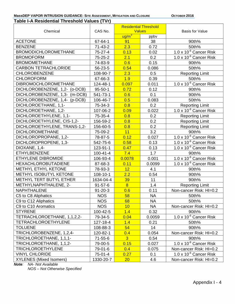
MassDEP VAPOR INTRUSION GUIDANCE: SITE ASSESSMENT, MITIGATION AND CLOSURE OCTOBER 2016
Appendix I - 4
Table I-A Residential Threshold Values (TVr)
Chemical CAS No. Residential Threshold
Values Basis for Value
ug/m3 ppbv
ACETONE 67-64-1 91 38 90th% BENZENE 71-43-2 2.3 0.72 50th% BROMODICHLOROMETHANE 75-27-4 0.13 0.02 1.0 x 10⁻⁶ Cancer Risk BROMOFORM 75-25-2 2.1 0.2 1.0 x 10⁻⁶ Cancer Risk BROMOMETHANE 74-83-9 0.6 0.15 90th% CARBON TETRACHLORIDE 56-23-5 0.54 0.086 50th% CHLOROBENZENE 108-90-7 2.3 0.5 Reporting Limit CHLOROFORM 67-66-3 1.9 0.39 50th% DIBROMOCHLOROMETHANE 124-48-1 0.097 0.011 1.0 x 10⁻⁶ Cancer Risk DICHLOROBENZENE, 1,2- (o-DCB) 95-50-1 0.72 0.12 90th% DICHLOROBENZENE, 1,3- (m-DCB) 541-73-1 0.6 0.1 90th% DICHLOROBENZENE, 1,4- (p-DCB) 106-46-7 0.5 0.083 50th% DICHLOROETHANE, 1,1- 75-34-3 0.8 0.2 Reporting Limit DICHLOROETHANE, 1,2- 107-06-2 0.09 0.022 1.0 x 10⁻⁶ Cancer Risk DICHLOROETHYLENE, 1,1- 75-35-4 0.8 0.2 Reporting Limit DICHLOROETHYLENE, CIS-1,2- 156-59-2 0.8 0.2 Reporting Limit DICHLOROETHYLENE, TRANS-1,2- 156-60-5 0.8 0.2 Reporting Limit DICHLOROMETHANE 75-09-2 11 3.2 90th% DICHLOROPROPANE, 1,2- 78-87-5 0.12 0.027 1.0 x 10⁻⁶ Cancer Risk DICHLOROPROPENE, 1,3- 542-75-6 0.58 0.13 1.0 x 10⁻⁶ Cancer Risk DIOXANE, 1,4- 123-91-1 0.47 0.13 1.0 x 10⁻⁶ Cancer Risk ETHYLBENZENE 100-41-4 7.4 1.7 90th% ETHYLENE DIBROMIDE 106-93-4 0.0078 0.001 1.0 x 10⁻⁶ Cancer Risk HEXACHLOROBUTADIENE 87-68-3 0.11 0.0099 1.0 x 10⁻⁶ Cancer Risk METHYL ETHYL KETONE 78-93-3 12 4.1 90th% METHYL ISOBUTYL KETONE 108-10-1 2.2 0.54 90th% METHYL TERT BUTYL ETHER 1634-04-4 39 11 90th% METHYLNAPHTHALENE, 2- 91-57-6 8 1.4 Reporting Limit NAPHTHALENE 91-20-3 0.6 0.11 Non-cancer Risk: HI=0.2 C5 to C8 Aliphatics NOS 58 NA 50th% C9 to C12 Aliphatics NOS 68 NA 50th% C9 to C10 Aromatics NOS 10 NA Non-cancer Risk: HI=0.2 STYRENE 100-42-5 1.4 0.32 90th% TETRACHLOROETHANE, 1,1,2,2- 79-34-5 0.04 0.0059 1.0 x 10⁻⁶ Cancer Risk TETRACHLOROETHYLENE 127-18-4 1.4 0.21 50th% TOLUENE 108-88-3 54 14 90th% TRICHLOROBENZENE, 1,2,4- 120-82-1 0.4 0.054 Non-cancer Risk: HI=0.2 TRICHLOROETHANE, 1,1,1- 71-55-6 3 0.54 90th% TRICHLOROETHANE, 1,1,2- 79-00-5 0.15 0.027 1.0 x 10⁻⁶ Cancer Risk TRICHLOROETHYLENE 79-01-6 0.4 0.075 Non-cancer Risk: HI=0.2 VINYL CHLORIDE 75-01-4 0.27 0.1 1.0 x 10⁻⁶ Cancer Risk XYLENES (Mixed Isomers) 1330-20-7 20 4.6 Non-cancer Risk: HI=0.2
Note: NA- Not Available NOS – Not Otherwise Specified
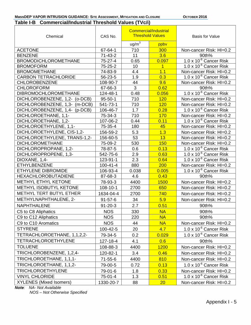
MassDEP VAPOR INTRUSION GUIDANCE: SITE ASSESSMENT, MITIGATION AND CLOSURE OCTOBER 2016
Appendix I - 5
Table I-B Commercial/Industrial Threshold Values (TVc/i)
Chemical CAS No.
Commercial/Industrial Threshold Values Basis for Value
ug/m3 ppbv
ACETONE 67-64-1 710 300 Non-cancer Risk: HI=0.2 BENZENE 71-43-2 11 3.6 90th% BROMODICHLOROMETHANE 75-27-4 0.65 0.097 1.0 x 10⁻⁶ Cancer Risk BROMOFORM 75-25-2 10 1 1.0 x 10⁻⁶ Cancer Risk BROMOMETHANE 74-83-9 4.4 1.1 Non-cancer Risk: HI=0.2 CARBON TETRACHLORIDE 56-23-5 1.9 0.3 1.0 x 10⁻⁶ Cancer Risk CHLOROBENZENE 108-90-7 44 9.6 Non-cancer Risk: HI=0.2 CHLOROFORM 67-66-3 3 0.62 90th% DIBROMOCHLOROMETHANE 124-48-1 0.48 0.056 1.0 x 10⁻⁶ Cancer Risk DICHLOROBENZENE, 1,2- (o-DCB) 95-50-1 710 120 Non-cancer Risk: HI=0.2 DICHLOROBENZENE, 1,3- (m-DCB) 541-73-1 710 120 Non-cancer Risk: HI=0.2 DICHLOROBENZENE, 1,4- (p-DCB) 106-46-7 1.7 0.28 1.0 x 10⁻⁶ Cancer Risk DICHLOROETHANE, 1,1- 75-34-3 710 170 Non-cancer Risk: HI=0.2 DICHLOROETHANE, 1,2- 107-06-2 0.44 0.11 1.0 x 10⁻⁶ Cancer Risk DICHLOROETHYLENE, 1,1- 75-35-4 180 45 Non-cancer Risk: HI=0.2 DICHLOROETHYLENE, CIS-1,2- 156-59-2 5.3 1.3 Non-cancer Risk: HI=0.2 DICHLOROETHYLENE, TRANS-1,2- 156-60-5 53 13 Non-cancer Risk: HI=0.2 DICHLOROMETHANE 75-09-2 530 150 Non-cancer Risk: HI=0.2 DICHLOROPROPANE, 1,2- 78-87-5 0.6 0.13 1.0 x 10⁻⁶ Cancer Risk DICHLOROPROPENE, 1,3- 542-75-6 2.9 0.63 1.0 x 10⁻⁶ Cancer Risk DIOXANE, 1,4- 123-91-1 2.3 0.64 1.0 x 10⁻⁶ Cancer Risk ETHYLBENZENE 100-41-4 880 200 Non-cancer Risk: HI=0.2 ETHYLENE DIBROMIDE 106-93-4 0.038 0.005 1.0 x 10⁻⁶ Cancer Risk HEXACHLOROBUTADIENE 87-68-3 4.6 0.43 90th% METHYL ETHYL KETONE 78-93-3 4400 1500 Non-cancer Risk: HI=0.2 METHYL ISOBUTYL KETONE 108-10-1 2700 650 Non-cancer Risk: HI=0.2 METHYL TERT BUTYL ETHER 1634-04-4 2700 740 Non-cancer Risk: HI=0.2 METHYLNAPHTHALENE, 2- 91-57-6 34 5.9 Non-cancer Risk: HI=0.2
NAPHTHALENE 91-20-3 2.7 0.51 90th%
C5 to C8 Aliphatics NOS 330 NA 90th% C9 to C12 Aliphatics NOS 220 NA 90th%
C9 to C10 Aromatics NOS 44 NA Non-cancer Risk: HI=0.2 STYRENE 100-42-5 20 4.7 1.0 x 10⁻⁶ Cancer Risk TETRACHLOROETHANE, 1,1,2,2- 79-34-5 0.2 0.029 1.0 x 10⁻⁶ Cancer Risk TETRACHLOROETHYLENE 127-18-4 4.1 0.6 90th% TOLUENE 108-88-3 4400 1200 Non-cancer Risk: HI=0.2 TRICHLOROBENZENE, 1,2,4- 120-82-1 3.4 0.46 Non-cancer Risk: HI=0.2 TRICHLOROETHANE, 1,1,1- 71-55-6 4400 810 Non-cancer Risk: HI=0.2 TRICHLOROETHANE, 1,1,2- 79-00-5 0.72 0.13 1.0 x 10⁻⁶ Cancer Risk TRICHLOROETHYLENE 79-01-6 1.8 0.33 Non-cancer Risk: HI=0.2 VINYL CHLORIDE 75-01-4 1.3 0.51 1.0 x 10⁻⁶ Cancer Risk XYLENES (Mixed Isomers) 1330-20-7 88 20 Non-cancer Risk: HI=0.2
Note: NA- Not Available NOS – Not Otherwise Specified
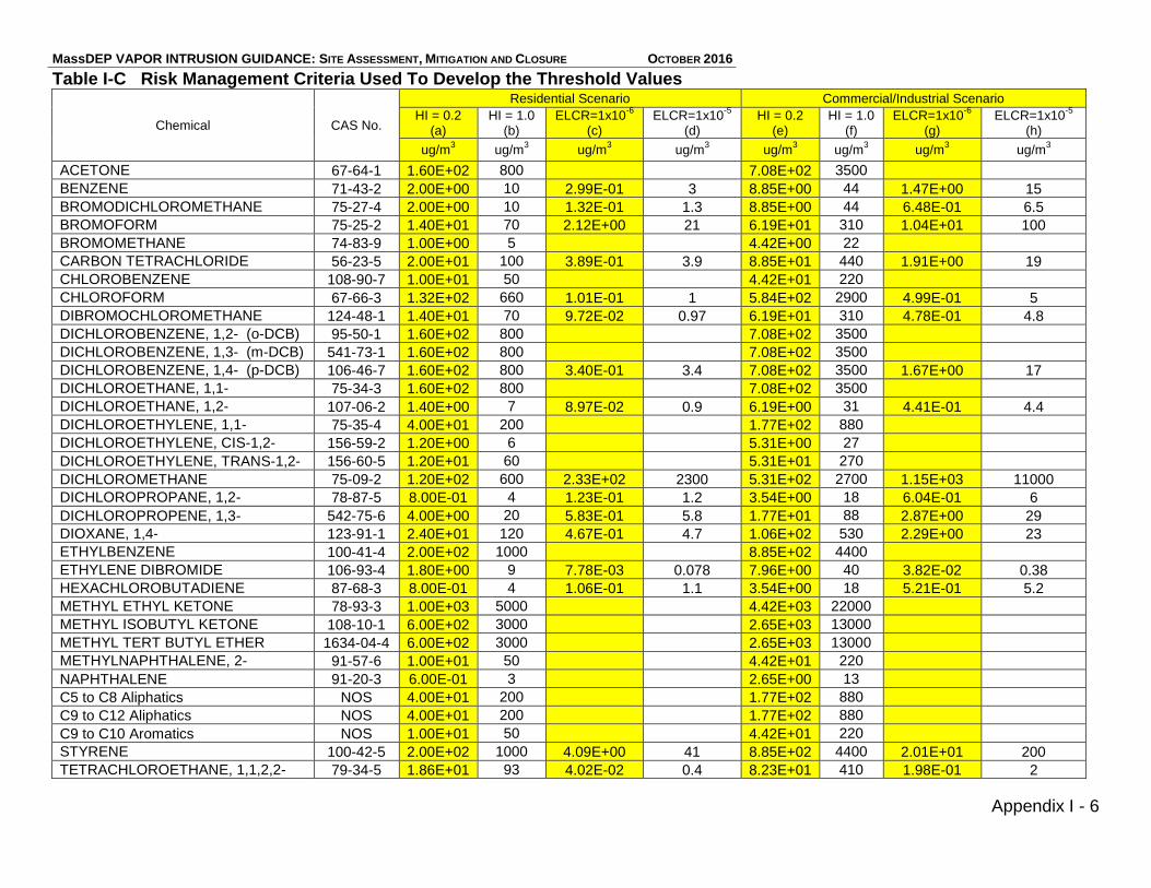
MassDEP VAPOR INTRUSION GUIDANCE: SITE ASSESSMENT, MITIGATION AND CLOSURE OCTOBER 2016
Appendix I - 6
Table I-C Risk Management Criteria Used To Develop the Threshold Values
Chemical CAS No.
Residential Scenario Commercial/Industrial Scenario
HI = 0.2 (a)
HI = 1.0 (b)
ELCR=1x10⁻⁶
(c)
ELCR=1x10⁻⁵
(d) HI = 0.2
(e) HI = 1.0
(f) ELCR=1x10
-6
(g) ELCR=1x10
-5
(h)
ug/m3 ug/m
3 ug/m
3 ug/m
3 ug/m
3 ug/m
3 ug/m
3 ug/m
3
ACETONE 67-64-1 1.60E+02 800 7.08E+02 3500
BENZENE 71-43-2 2.00E+00 10 2.99E-01 3 8.85E+00 44 1.47E+00 15
BROMODICHLOROMETHANE 75-27-4 2.00E+00 10 1.32E-01 1.3 8.85E+00 44 6.48E-01 6.5
BROMOFORM 75-25-2 1.40E+01 70 2.12E+00 21 6.19E+01 310 1.04E+01 100
BROMOMETHANE 74-83-9 1.00E+00 5 4.42E+00 22
CARBON TETRACHLORIDE 56-23-5 2.00E+01 100 3.89E-01 3.9 8.85E+01 440 1.91E+00 19
CHLOROBENZENE 108-90-7 1.00E+01 50 4.42E+01 220
CHLOROFORM 67-66-3 1.32E+02 660 1.01E-01 1 5.84E+02 2900 4.99E-01 5
DIBROMOCHLOROMETHANE 124-48-1 1.40E+01 70 9.72E-02 0.97 6.19E+01 310 4.78E-01 4.8
DICHLOROBENZENE, 1,2- (o-DCB) 95-50-1 1.60E+02 800 7.08E+02 3500
DICHLOROBENZENE, 1,3- (m-DCB) 541-73-1 1.60E+02 800 7.08E+02 3500
DICHLOROBENZENE, 1,4- (p-DCB) 106-46-7 1.60E+02 800 3.40E-01 3.4 7.08E+02 3500 1.67E+00 17
DICHLOROETHANE, 1,1- 75-34-3 1.60E+02 800 7.08E+02 3500
DICHLOROETHANE, 1,2- 107-06-2 1.40E+00 7 8.97E-02 0.9 6.19E+00 31 4.41E-01 4.4
DICHLOROETHYLENE, 1,1- 75-35-4 4.00E+01 200 1.77E+02 880
DICHLOROETHYLENE, CIS-1,2- 156-59-2 1.20E+00 6 5.31E+00 27
DICHLOROETHYLENE, TRANS-1,2- 156-60-5 1.20E+01 60 5.31E+01 270
DICHLOROMETHANE 75-09-2 1.20E+02 600 2.33E+02 2300 5.31E+02 2700 1.15E+03 11000
DICHLOROPROPANE, 1,2- 78-87-5 8.00E-01 4 1.23E-01 1.2 3.54E+00 18 6.04E-01 6
DICHLOROPROPENE, 1,3- 542-75-6 4.00E+00 20 5.83E-01 5.8 1.77E+01 88 2.87E+00 29
DIOXANE, 1,4- 123-91-1 2.40E+01 120 4.67E-01 4.7 1.06E+02 530 2.29E+00 23
ETHYLBENZENE 100-41-4 2.00E+02 1000 8.85E+02 4400
ETHYLENE DIBROMIDE 106-93-4 1.80E+00 9 7.78E-03 0.078 7.96E+00 40 3.82E-02 0.38
HEXACHLOROBUTADIENE 87-68-3 8.00E-01 4 1.06E-01 1.1 3.54E+00 18 5.21E-01 5.2
METHYL ETHYL KETONE 78-93-3 1.00E+03 5000 4.42E+03 22000
METHYL ISOBUTYL KETONE 108-10-1 6.00E+02 3000 2.65E+03 13000
METHYL TERT BUTYL ETHER 1634-04-4 6.00E+02 3000 2.65E+03 13000
METHYLNAPHTHALENE, 2- 91-57-6 1.00E+01 50 4.42E+01 220
NAPHTHALENE 91-20-3 6.00E-01 3 2.65E+00 13
C5 to C8 Aliphatics NOS 4.00E+01 200 1.77E+02 880
C9 to C12 Aliphatics NOS 4.00E+01 200 1.77E+02 880
C9 to C10 Aromatics NOS 1.00E+01 50 4.42E+01 220
STYRENE 100-42-5 2.00E+02 1000 4.09E+00 41 8.85E+02 4400 2.01E+01 200
TETRACHLOROETHANE, 1,1,2,2- 79-34-5 1.86E+01 93 4.02E-02 0.4 8.23E+01 410 1.98E-01 2
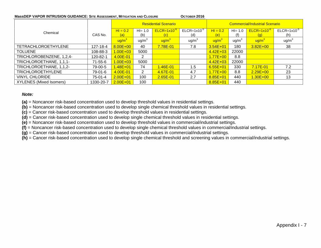
MassDEP VAPOR INTRUSION GUIDANCE: SITE ASSESSMENT, MITIGATION AND CLOSURE OCTOBER 2016
Appendix I - 7
Residential Scenario Commercial/Industrial Scenario
Chemical CAS No.
HI = 0.2 (a)
HI= 1.0 (b)
ELCR=1x10⁻⁶
(c)
ELCR=1x10⁻⁵
(d) HI = 0.2
(e) HI= 1.0
(f) ELCR=1x10
-6
(g) ELCR=1x10
-5
(h)
ug/m3 ug/m
3 ug/m
3 ug/m
3 ug/m
3 ug/m
3 ug/m
3 ug/m
3
TETRACHLOROETHYLENE 127-18-4 8.00E+00 40 7.78E-01 7.8 3.54E+01 180 3.82E+00 38
TOLUENE 108-88-3 1.00E+03 5000 4.42E+03 22000
TRICHLOROBENZENE, 1,2,4- 120-82-1 4.00E-01 2 1.77E+00 8.8
TRICHLOROETHANE, 1,1,1- 71-55-6 1.00E+03 5000 4.42E+03 22000
TRICHLOROETHANE, 1,1,2- 79-00-5 1.48E+01 74 1.46E-01 1.5 6.55E+01 330 7.17E-01 7.2
TRICHLOROETHYLENE 79-01-6 4.00E-01 2 4.67E-01 4.7 1.77E+00 8.8 2.29E+00 23
VINYL CHLORIDE 75-01-4 2.00E+01 100 2.65E-01 2.7 8.85E+01 440 1.30E+00 13
XYLENES (Mixed Isomers) 1330-20-7 2.00E+01 100 8.85E+01 440
Note:
(a) = Noncancer risk-based concentration used to develop threshold values in residential settings. (b) = Noncancer risk-based concentration used to develop single chemical threshold values in residential settings. (c) = Cancer risk-based concentration used to develop threshold values in residential settings. (d) = Cancer risk-based concentration used to develop single chemical threshold values in residential settings. (e) = Noncancer risk-based concentration used to develop threshold values in commercial/industrial settings. (f) = Noncancer risk-based concentration used to develop single chemical threshold values in commercial/industrial settings. (g) = Cancer risk-based concentration used to develop threshold values in commercial/industrial settings. (h) = Cancer risk-based concentration used to develop single chemical threshold and screening values in commercial/industrial settings.
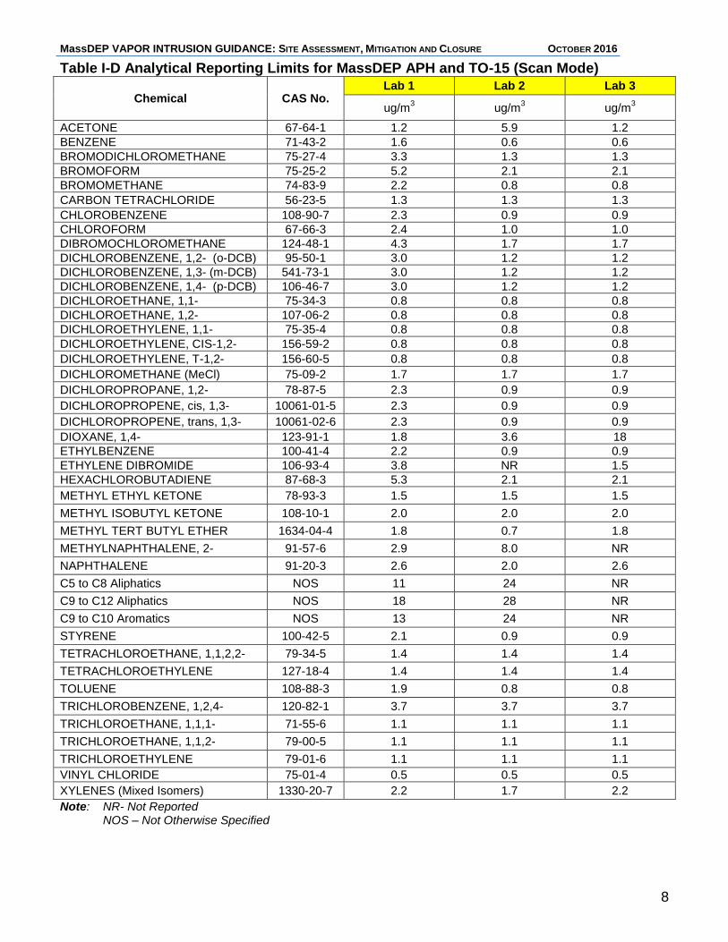
MassDEP VAPOR INTRUSION GUIDANCE: SITE ASSESSMENT, MITIGATION AND CLOSURE OCTOBER 2016
8
Table I-D Analytical Reporting Limits for MassDEP APH and TO-15 (Scan Mode)
Chemical CAS No. Lab 1 Lab 2 Lab 3
ug/m3 ug/m
3 ug/m
3
ACETONE 67-64-1 1.2 5.9 1.2
BENZENE 71-43-2 1.6 0.6 0.6
BROMODICHLOROMETHANE 75-27-4 3.3 1.3 1.3
BROMOFORM 75-25-2 5.2 2.1 2.1
BROMOMETHANE 74-83-9 2.2 0.8 0.8
CARBON TETRACHLORIDE 56-23-5 1.3 1.3 1.3
CHLOROBENZENE 108-90-7 2.3 0.9 0.9
CHLOROFORM 67-66-3 2.4 1.0 1.0
DIBROMOCHLOROMETHANE 124-48-1 4.3 1.7 1.7
DICHLOROBENZENE, 1,2- (o-DCB) 95-50-1 3.0 1.2 1.2
DICHLOROBENZENE, 1,3- (m-DCB) 541-73-1 3.0 1.2 1.2
DICHLOROBENZENE, 1,4- (p-DCB) 106-46-7 3.0 1.2 1.2
DICHLOROETHANE, 1,1- 75-34-3 0.8 0.8 0.8
DICHLOROETHANE, 1,2- 107-06-2 0.8 0.8 0.8
DICHLOROETHYLENE, 1,1- 75-35-4 0.8 0.8 0.8
DICHLOROETHYLENE, CIS-1,2- 156-59-2 0.8 0.8 0.8
DICHLOROETHYLENE, T-1,2- 156-60-5 0.8 0.8 0.8
DICHLOROMETHANE (MeCl) 75-09-2 1.7 1.7 1.7
DICHLOROPROPANE, 1,2- 78-87-5 2.3 0.9 0.9
DICHLOROPROPENE, cis, 1,3- 10061-01-5 2.3 0.9 0.9
DICHLOROPROPENE, trans, 1,3- 10061-02-6 2.3 0.9 0.9
DIOXANE, 1,4- 123-91-1 1.8 3.6 18
ETHYLBENZENE 100-41-4 2.2 0.9 0.9
ETHYLENE DIBROMIDE 106-93-4 3.8 NR 1.5
HEXACHLOROBUTADIENE 87-68-3 5.3 2.1 2.1
METHYL ETHYL KETONE 78-93-3 1.5 1.5 1.5
METHYL ISOBUTYL KETONE 108-10-1 2.0 2.0 2.0
METHYL TERT BUTYL ETHER 1634-04-4 1.8 0.7 1.8
METHYLNAPHTHALENE, 2- 91-57-6 2.9 8.0 NR
NAPHTHALENE 91-20-3 2.6 2.0 2.6
C5 to C8 Aliphatics NOS 11 24 NR
C9 to C12 Aliphatics NOS 18 28 NR
C9 to C10 Aromatics NOS 13 24 NR
STYRENE 100-42-5 2.1 0.9 0.9
TETRACHLOROETHANE, 1,1,2,2- 79-34-5 1.4 1.4 1.4
TETRACHLOROETHYLENE 127-18-4 1.4 1.4 1.4
TOLUENE 108-88-3 1.9 0.8 0.8
TRICHLOROBENZENE, 1,2,4- 120-82-1 3.7 3.7 3.7
TRICHLOROETHANE, 1,1,1- 71-55-6 1.1 1.1 1.1
TRICHLOROETHANE, 1,1,2- 79-00-5 1.1 1.1 1.1
TRICHLOROETHYLENE 79-01-6 1.1 1.1 1.1
VINYL CHLORIDE 75-01-4 0.5 0.5 0.5
XYLENES (Mixed Isomers) 1330-20-7 2.2 1.7 2.2
Note: NR- Not Reported NOS – Not Otherwise Specified
MassDEP VAPOR INTRUSION GUIDANCE: SITE ASSESSMENT, MITIGATION AND CLOSURE OCTOBER 2016
Appendix II
Sub-Slab Soil Gas Screening Values

MassDEP VAPOR INTRUSION GUIDANCE: SITE ASSESSMENT, MITIGATION AND CLOSURE OCTOBER 2016
MassDEP VAPOR INTRUSION GUIDANCE: SITE ASSESSMENT, MITIGATION AND CLOSURE OCTOBER 2016
Appendix II-1
Appendix II - Sub-Slab Soil Gas Screening Values II.A Introduction MassDEP has developed screening criteria for sub-slab soil gas results to be used in a Lines of Evidence evaluation of vapor intrusion. These screening criteria are based on Threshold Values (TVs) discussed in Appendix I and a generic sub-slab soil gas-to-indoor air dilution factor presented in more detail below. II.B Derivation of Sub-Slab Soil Gas Screening Values The Sub-slab Soil Gas Screening Values (SSGSVs) were derived by multiplying the TVs by a generic sub-slab soil gas-to-indoor air dilution factor of 70. The dilution factor of 70 is meant to reflect the attenuation of soil gases in the sub-slab. This generic dilution factor corresponds to the inverse of the 80th percentile of the sub-slab soil gas attenuation factors in the USEPA’s database (Figure 11b, USEPA’s Vapor Intrusion Database: Preliminary evaluation of attenuation factors, Draft, Office of Solid Waste, March 4, 2008). The 70-fold attenuation was subsequently compared to USEPA's 2012 Final Vapor Intrusion Database sub-slab soil gas attenuation factors. The 2012 attenuation distributions are similar to the 2008 data. The 2008 attenuation (1.4 E-2 or 70) was compared to attenuation distributions in Table 6 of the 2012 report. The 75th percentile attenuation value for the 2012 distribution, which had background data removed, was 1.2 E-2 (dilution factor of 90) and the 95th percentile value of 1.8E-1 (dilution factor of 5.5). After its review of USEPA's 2012 sub-slab soil gas attenuation factors, MassDEP chose to retain the 80th percentile attenuation value from the 2008 data as a reasonably conservative estimate of sub-slab soil gas attenuation. Choosing the 80th percentile means that roughly 80% or 4 out of 5 buildings would be expected to have more sub-slab attenuation, and roughly one out of 5, or 20% would be expected to have less sub-slab attenuation. II.C Use of the Sub-Slab Soil Gas Screening Values As described in Section 2.2.2, SSGSVs are intended to be used in conjunction with soil gas data obtained within a few inches beneath the slab. Sampling techniques are outlined in Appendix III. Soil gas directly beneath a slab or basement is most likely to be representative of what may be entering the building. The generic attenuation factor of 70 applies equally to all VOCs. This attenuation factor assumes petroleum and non-petroleum VOCs attenuate similarly in the sub-slab environment in contrast to the significant attenuation that can occur with petroleum compounds in deep soil gas. In an effort to determine if petroleum compounds were more likely to be attenuated than other VOCs in the sub-slab environment, petroleum
MassDEP VAPOR INTRUSION GUIDANCE: SITE ASSESSMENT, MITIGATION AND CLOSURE OCTOBER 2016
Appendix II-2
data presented in the USEPA database was analyzed by MassDEP. While limited (3% of the USEPA database is comprised of petroleum-related compounds), this data combined with site-related sub-slab data suggest that petroleum-related compounds typically migrate from the shallow sub-slab soil gas (directly beneath the slab) to indoor air to an extent similar to other volatile compounds. In general, representative sub-slab soil gas concentrations less than the SSGSVs indicate that the vapor intrusion pathway is unlikely to be of concern under current site conditions and use.
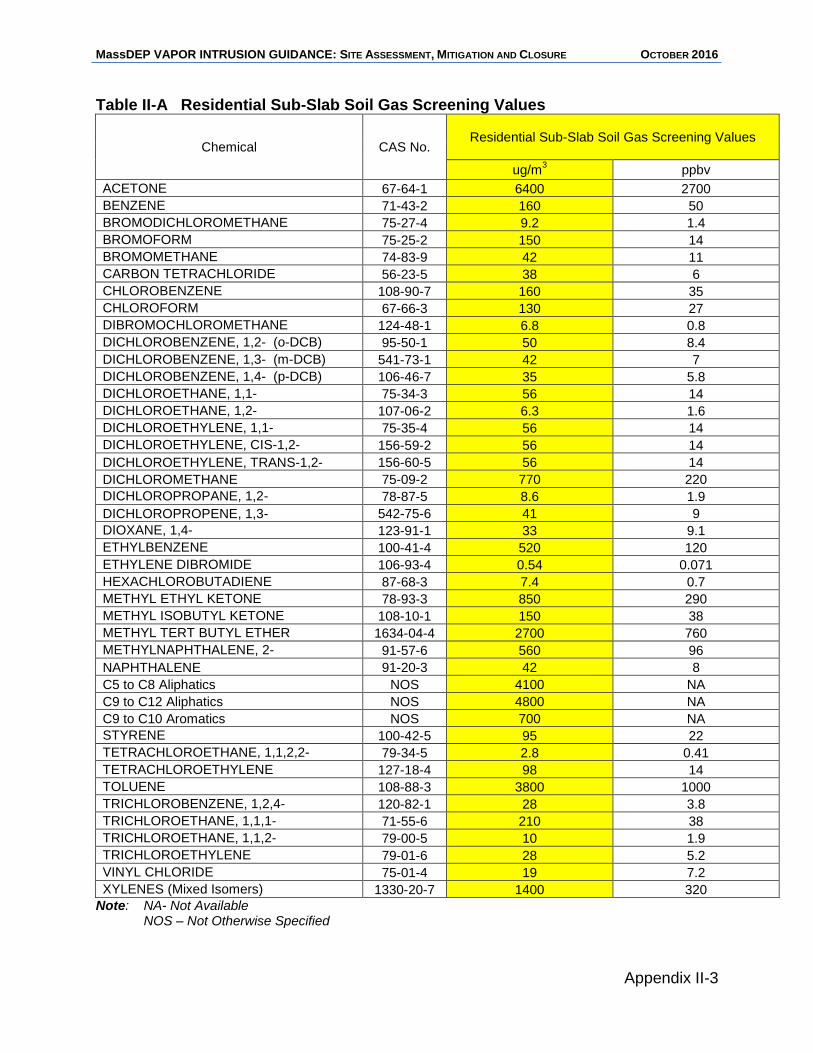
MassDEP VAPOR INTRUSION GUIDANCE: SITE ASSESSMENT, MITIGATION AND CLOSURE OCTOBER 2016
Appendix II-3
Table II-A Residential Sub-Slab Soil Gas Screening Values
Chemical CAS No. Residential Sub-Slab Soil Gas Screening Values
ug/m3 ppbv
ACETONE 67-64-1 6400 2700
BENZENE 71-43-2 160 50
BROMODICHLOROMETHANE 75-27-4 9.2 1.4
BROMOFORM 75-25-2 150 14
BROMOMETHANE 74-83-9 42 11
CARBON TETRACHLORIDE 56-23-5 38 6
CHLOROBENZENE 108-90-7 160 35
CHLOROFORM 67-66-3 130 27
DIBROMOCHLOROMETHANE 124-48-1 6.8 0.8
DICHLOROBENZENE, 1,2- (o-DCB) 95-50-1 50 8.4
DICHLOROBENZENE, 1,3- (m-DCB) 541-73-1 42 7
DICHLOROBENZENE, 1,4- (p-DCB) 106-46-7 35 5.8
DICHLOROETHANE, 1,1- 75-34-3 56 14
DICHLOROETHANE, 1,2- 107-06-2 6.3 1.6
DICHLOROETHYLENE, 1,1- 75-35-4 56 14
DICHLOROETHYLENE, CIS-1,2- 156-59-2 56 14
DICHLOROETHYLENE, TRANS-1,2- 156-60-5 56 14
DICHLOROMETHANE 75-09-2 770 220
DICHLOROPROPANE, 1,2- 78-87-5 8.6 1.9
DICHLOROPROPENE, 1,3- 542-75-6 41 9
DIOXANE, 1,4- 123-91-1 33 9.1
ETHYLBENZENE 100-41-4 520 120
ETHYLENE DIBROMIDE 106-93-4 0.54 0.071
HEXACHLOROBUTADIENE 87-68-3 7.4 0.7
METHYL ETHYL KETONE 78-93-3 850 290
METHYL ISOBUTYL KETONE 108-10-1 150 38
METHYL TERT BUTYL ETHER 1634-04-4 2700 760
METHYLNAPHTHALENE, 2- 91-57-6 560 96
NAPHTHALENE 91-20-3 42 8
C5 to C8 Aliphatics NOS 4100 NA
C9 to C12 Aliphatics NOS 4800 NA
C9 to C10 Aromatics NOS 700 NA
STYRENE 100-42-5 95 22
TETRACHLOROETHANE, 1,1,2,2- 79-34-5 2.8 0.41
TETRACHLOROETHYLENE 127-18-4 98 14
TOLUENE 108-88-3 3800 1000
TRICHLOROBENZENE, 1,2,4- 120-82-1 28 3.8
TRICHLOROETHANE, 1,1,1- 71-55-6 210 38
TRICHLOROETHANE, 1,1,2- 79-00-5 10 1.9
TRICHLOROETHYLENE 79-01-6 28 5.2
VINYL CHLORIDE 75-01-4 19 7.2
XYLENES (Mixed Isomers) 1330-20-7 1400 320
Note: NA- Not Available NOS – Not Otherwise Specified
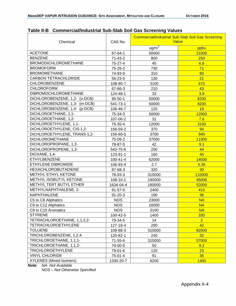
MassDEP VAPOR INTRUSION GUIDANCE: SITE ASSESSMENT, MITIGATION AND CLOSURE OCTOBER 2016
Appendix II-4
Table II-B Commercial/Industrial Sub-Slab Soil Gas Screening Values
Chemical CAS No.
Commercial/Industrial Sub-Slab Soil Gas Screening Value
ug/m3 ppbv
ACETONE 67-64-1 50000 21000
BENZENE 71-43-2 800 250
BROMODICHLOROMETHANE 75-27-4 45 6.8
BROMOFORM 75-25-2 730 71
BROMOMETHANE 74-83-9 310 80
CARBON TETRACHLORIDE 56-23-5 130 21
CHLOROBENZENE 108-90-7 3100 670
CHLOROFORM 67-66-3 210 43
DIBROMOCHLOROMETHANE 124-48-1 33 3.9
DICHLOROBENZENE, 1,2- (o-DCB) 95-50-1 50000 8200
DICHLOROBENZENE, 1,3- (m-DCB) 541-73-1 50000 8200
DICHLOROBENZENE, 1,4- (p-DCB) 106-46-7 120 19
DICHLOROETHANE, 1,1- 75-34-3 50000 12000
DICHLOROETHANE, 1,2- 107-06-2 31 7.6
DICHLOROETHYLENE, 1,1- 75-35-4 12000 3100
DICHLOROETHYLENE, CIS-1,2- 156-59-2 370 94
DICHLOROETHYLENE, TRANS-1,2- 156-60-5 3700 940
DICHLOROMETHANE 75-09-2 37000 11000
DICHLOROPROPANE, 1,2- 78-87-5 42 9.1
DICHLOROPROPENE, 1,3- 542-75-6 200 44
DIOXANE, 1,4- 123-91-1 160 45
ETHYLBENZENE 100-41-4 62000 14000
ETHYLENE DIBROMIDE 106-93-4 2.7 0.35
HEXACHLOROBUTADIENE 87-68-3 320 30
METHYL ETHYL KETONE 78-93-3 310000 110000
METHYL ISOBUTYL KETONE 108-10-1 190000 45000
METHYL TERT BUTYL ETHER 1634-04-4 190000 52000
METHYLNAPHTHALENE, 2- 91-57-6 2400 410
NAPHTHALENE 91-20-3 190 36
C5 to C8 Aliphatics NOS 23000 NA
C9 to C12 Aliphatics NOS 16000 NA
C9 to C10 Aromatics NOS 3100 NA
STYRENE 100-42-5 1400 330
TETRACHLOROETHANE, 1,1,2,2- 79-34-5 14 2
TETRACHLOROETHYLENE 127-18-4 290 42
TOLUENE 108-88-3 310000 82000
TRICHLOROBENZENE, 1,2,4- 120-82-1 240 32
TRICHLOROETHANE, 1,1,1- 71-55-6 310000 57000
TRICHLOROETHANE, 1,1,2- 79-00-5 50 9.2
TRICHLOROETHYLENE 79-01-6 120 23
VINYL CHLORIDE 75-01-4 91 35
XYLENES (Mixed Isomers) 1330-20-7 6200 1400
Note: NA- Not Available NOS – Not Otherwise Specified
MassDEP VAPOR INTRUSION GUIDANCE: SITE ASSESSMENT, MITIGATION AND CLOSURE OCTOBER 2016
Appendix III
Air Sampling Information

MassDEP VAPOR INTRUSION GUIDANCE: SITE ASSESSMENT, MITIGATION AND CLOSURE OCTOBER 2016
MassDEP VAPOR INTRUSION GUIDANCE: SITE ASSESSMENT, MITIGATION AND CLOSURE OCTOBER 2016
Appendix III-i
Appendix III - Air Sampling Information
Table of Contents
Section III.A Introduction Section III.B Sample Collection
B.1 Indoor Air Product Survey B.2 Collection Techniques
Real-time Sampling and Measurement Grab and Time-Weighted Sampling
B.3 Collection equipment Evacuated Canisters Glass Vials Passive Badge Samplers Sorbent Tubes Tedlar Bags
B.4 Representative Indoor and Outdoor Air Sampling Weather Windows and Doors Mechanical Ventilation Systems Confounding Sources
Section III.C Procedures for the Collection of Sub-Slab Soil Gas Samples Section III.D Sample Analytical Methods
Field Analytical Methods Laboratory Analytical Methods
Section III.E Sample Quality Data Quality Objectives Sample Quality Assurance and Quality Control
Section III.F Instructions for Residents of Homes to Be Sampled
Section III.G Indoor Air Quality Building Survey

MassDEP VAPOR INTRUSION GUIDANCE: SITE ASSESSMENT, MITIGATION AND CLOSURE OCTOBER 2016
MassDEP VAPOR INTRUSION GUIDANCE: SITE ASSESSMENT, MITIGATION AND CLOSURE OCTOBER 2016
Appendix III-1
Appendix III - Air Sampling Information III.A Introduction This appendix provides information on air sampling and analysis to determine contaminant concentrations in sub-slab soil gas, indoor air and outdoor air as part of vapor intrusion investigations, risk characterizations, and monitoring. While many methods exist to collect and analyze contamination in air, this appendix discusses some of the more common methods, with an emphasis on those that are recommended by MassDEP. Air sampling and analytical methods must yield a level of data quality commensurate with the intended data use. Section 2 of this document (Assessment) provides guidance on considerations for sampling indoor air, outdoor air, sub-slab soil gas and exterior soil-gas in the context of various vapor intrusion pathway assessment objectives.
III.B Sample Collection III.B.1 Indoor Air VOC Product Survey and Removal Prior to Sampling Before collecting indoor air samples, a survey of the building should be made to locate and remove any VOC-containing products or materials that could contribute to the levels of the Contaminants of Concern in the building. An Indoor Air Building Survey Form can be used as a checklist to help identify items for removal and document information about the building products, materials, conditions and use at the time of sampling. Additionally, it recommended that building residents/users be provided instructions to help to reduce the presence of contaminants from their activities prior to and during the sampling period. An example of instructions for building residents and Indoor Air Quality Building Survey Form are provided as an attachment to this appendix.11 See also the related discussion of Confounding Sources below (III.B.4). III.B.2 Collection Techniques Collection techniques implemented in the field can be divided into three categories:
Real-time sampling and measurement;
Grab sampling;
Time-weighted sampling. Real-time Sampling and Measurement Real-time sampling and measurement for VOCs typically measures Total Organic Vapors (TOVs), rather than individual chemicals, and combines both air sampling and
11
Instructions for Building Residents and the Indoor Air Building Survey Form were adapted from
New Hampshire Department of Environmental Services. 2006. Vapor Intrusion Guidance. Appendices C and D.
MassDEP VAPOR INTRUSION GUIDANCE: SITE ASSESSMENT, MITIGATION AND CLOSURE OCTOBER 2016
Appendix III-2
sample analysis into one procedure. Real-time data is often accomplished with hand held instruments that directly sample and measure TOVs in air instantaneously. Such instruments can have any of several detectors, and often use a Photo-ionization Detector (PID) or Flame Ionization Detector (FID). The use of real time measurement can be especially helpful early in the investigative process in identifying migration pathways into a structure, as well as hot spots within a building. Real-time measurement of TOVs in soil gas can be used to evaluate the extent and relative concentrations of contamination in the sub-surface. These results in turn can provide timely information for making response action decisions, including identifying areas where additional investigative efforts should be focused. As with any sampling and analytical technique, the application of real time TOV instruments must be commensurate with the intended use of the data. The precision, accuracy, representativeness, comparability and sensitivity of the data must be adequate to support decisions made based on such data. Grab (Short Duration) and Time-Weighted (Long Duration) Sampling Air samples are usually described as either grab samples or time-weighted samples, depending on the sampling duration. Air grab samples are those collected over a period of several seconds to several minutes. Air time-weighted samples are those collected over many minutes to many hours or days. The definition of a time-weighted air sample is “the average concentration of contaminants during a given period.” Grab samples provide more of a snapshot of chemical concentrations because of the very short duration of the sampling period. Time-weighted (or long duration samples) provide an average concentration across the longer period of time. MassDEP considers grab (short duration) samples sufficient for exterior soil gas and sub-slab soil gas samples. For sampling indoor air and outdoor air, time-weighted (long duration) sampling is generally recommended. Grab samples may be appropriate, however, for sampling and analysis of indoor air conducted to expedite the initial identification of a vapor intrusion pathway and Imminent Hazard condition or when used with long duration sampling to increase sampling density.
MassDEP recommends sampling durations of 24-hours for indoor air in residential buildings and for outdoor air data collection because a longer sampling duration is likely more representative of the actual exposures and fluctuations of indoor and outdoor air concentrations over time. For commercial buildings, MassDEP recommends an 8-hour sampling period during regular business hours, except where regular business activities would potentially contribute VOCs to the indoor air from confounding sources. Shorter sampling durations may be necessary for logistical reasons; in such cases four hours should be considered a minimum sampling duration. Indoor air grab samples can be used effectively to supplement the longer duration samples (24-hour and 8-hour) to increase sampling density and information about temporal variability occurring over a period of weeks or months. A series of 2 to 3 grab samples over several winter months analyzed using a portable GC/MS, for example, may provide a better indication of
MassDEP VAPOR INTRUSION GUIDANCE: SITE ASSESSMENT, MITIGATION AND CLOSURE OCTOBER 2016
Appendix III-3
temporal variability than a single 24-hour time weighted sample provided the data quality and Reporting Limits if the grab sample analyses meet data quality objectives for its intended use.
III.B.3 Collection Equipment A variety of collection equipment is available for air sampling. The selection of the collection method will depend on the intended use of the data and the associated data quality objectives. Some commonly used collection techniques are described below. Evacuated Canisters MassDEP considers the use of evacuated air sampling canisters as appropriate for the collection of either short duration or long duration samples. Evacuated canisters are recommended for the collection of indoor air samples to determine Exposure Point Concentrations. Air samples are collected into evacuated canisters that are under negative pressure relative to the environment. Canisters are generally stainless steel, with silica-lined interior, and typically available in 1-, 3- and 6- liter sizes. They are obtained from the analytical laboratory, and are typically ready to collect sample once a vacuum gauge is installed at the top of the canister. Canisters are fitted with flow controllers that will collect an air sample at a pre-set flow rate. The canister pressure should be recorded from the vacuum gauge before and after the sampling event. Indoor and outdoor air samples are collected by opening the canister valve. A sample inlet line made of stainless steel tubing is used to collect a soil gas sample. Additional information on the procedure for soil gas sampling using an evacuated canister is provided in Section III.C of this appendix. More detailed information regarding the collection of air samples in evacuated canisters can be found in:
ITRC (2014), Petroleum Vapor Intrusion Fundamentals of Screening, Investigation, and Management
USEPA OSWER (2015), Technical Guide For Assessing and Mitigating the Vapor Intrusion Pathway from Subsurface Vapor Sources to Indoor Air
USEPA (1999), Sampling procedures included in EPA Method TO-15, Compendium of Methods for the Determination of Toxic Organic Compounds in Ambient Air, Determination of Volatile Organic Compounds (VOCs) in Air Collected in Specially-Prepared Canisters and Analyzed by Gas Chromatography/Mass Spectrometry (GC/MS) (EPA/625/R-96-010b).
MassDEP VAPOR INTRUSION GUIDANCE: SITE ASSESSMENT, MITIGATION AND CLOSURE OCTOBER 2016
Appendix III-4
Glass Vials and Gas Sampling Bags MassDEP has achieved good results collecting grab samples for field screening in glass Volatile Organic Analysis (VOA) vials. The air sample is collected by flushing the vial using a portable air pump and immediately capping the vial. The sample is typically withdrawn from the vial for analysis by piercing the septum with a syringe. It can then be direct injected into a gas chromatograph. Additional information on the procedure using glass vial for the collection of soil gas samples is provided in Section III.C of this appendix. MassDEP also has experience collecting indoor air grab samples for field screening in
air sampling bags (1 liter Kynar or equivalent). Samples are collected over a short duration and analyzed within a 24- hour period with a GC or GC/MS. This approach allows for the generation of large amounts of screening data in a short period of time and can be particularly useful in an initial evaluation of indoor air concentrations. Gas sampling bags can have some application issues associated with contaminants adsorbing to the bag surface, high moisture levels interfering with sample recovery, and bag related contaminant peaks. The potential for these issues should be considered when using bag samplers. Field screening results must have a level of data quality commensurate with their intended use and should be evaluated for comparability with synoptic samples submitted for laboratory analysis. Passive Samplers Passive sampling devices, including sampling badges, typically contain an absorbent media such as charcoal, Carbopak or Tenax. The passive sampler is placed at the sampling location, and contaminants in air are sorbed onto it based on the principle that VOCs in air diffuse from an area of high concentration to an area of low concentration. There is no active pumping to obtain a specific volume of air to be collected by the passive sampler. As a result, the sample volume, and associated chemical concentrations in the sample are estimated by modeling of the diffusion rate.
The advantages of passive samplers include the ability to collect air samples over longer periods of time than some other sampling techniques, and sometimes lower sampling costs. The cost for sample analysis may not be lower. There are several recognized practical application issues with some passive samplers including interferences, the effects of high humidity, and back diffusion off the sampling medium. Passive samplers may be a useful and cost-effective tool for screening, but absent Quality Control data regarding sample size and calibration, passive sampling data are likely not sufficient for risk evaluation.
MassDEP VAPOR INTRUSION GUIDANCE: SITE ASSESSMENT, MITIGATION AND CLOSURE OCTOBER 2016
Appendix III-5
Sorbent Tubes
Sample collection onto sorbent tubes involves the pumping of the air sample through a tube packed with adsorbent media. Types of adsorbent media include charcoal, Tenax, and Carbopak. Tube sample collection flow rates are determined based on the adsorbent used, the target pollutant, and the amount (mass) of adsorbent contained in the trap. Care must be taken to avoid pumping more than the “breakthrough volume” of air into a tube, as sample loss may result. Safe sampling volumes are occasionally suggested by the laboratory supplier or manufacturer or specified for a particular set of parameters in the analytical method. Back-up tubes for detecting breakthrough may be necessary when tube sampling. When conducting tube sampling, pump flow rates should adjusted to make sure the breakthrough volume is not exceeded during the sample collection.
III.B.4 Representative Indoor Air Sampling Indoor air samples should be collected in a manner that will likely produce a reasonably conservative and representative estimate of the exposure to contaminants by occupants of the building. Therefore, samples should be collected from areas where the highest contamination is likely, with consideration of where the building occupants currently spend their time, and might spend their time in the future. Because lower floors are closer to where contamination is likely entering the building, indoor air concentrations attributable to vapor intrusion are usually higher on lower floors. This is generally due to less air mixing and dilution as compared to upper floors. Indoor air concentrations can vary over time, so longer air sampling durations will tend to average this variation and likely produce a better representation of the exposure experienced by building occupants than short duration samples. Samples that are intended to be representative of “worst case” conditions should be collected when the indoor air concentrations are likely to be higher. This usually includes conditions such as colder weather, with the heating system on and doors and windows closed. Samples collected for an IH evaluation should be collected in a timely way as soon as the potential IH has been identified, recognizing that conditions may not be worst case and that additional sampling may be necessary. Some of the factors to be considered in collecting indoor air samples are discussed below. Weather When assessing a potential vapor intrusion pathway, indoor air sampling should be conducted under weather conditions that are likely to result in a greater amount of vapor intrusion (worst-case conditions). Cold and rainy weather can result in higher indoor contaminant concentrations than warmer, dryer weather. Windy conditions can also result in higher indoor contaminant concentrations. Winds that are steady and exceed about five miles per hour may under-pressurize the building relative to the subsurface; soil gas entry into the building under these conditions is likely to be greater.
MassDEP VAPOR INTRUSION GUIDANCE: SITE ASSESSMENT, MITIGATION AND CLOSURE OCTOBER 2016
Appendix III-6
Windows and Doors Doors and windows should be adjusted to conditions under which vapor intrusion is most likely to occur. The pressure differential between inside and outside a structure is generally greatest when windows and doors are kept closed and the heating system is operating. Therefore, it is recommended that windows and doors to the outside be kept closed during sampling and, if possible, for a period of at least twenty-four to forty-eight hours before sampling is conducted.
Mechanical Ventilation Systems
The mechanics of a building’s HVAC system should be considered in determining appropriate conditions for sampling. Operation of an HVAC system can affect contaminant infiltration by creating a pressure differential that draws in more, or less, subsurface soil gas or by diluting indoor air levels. In some heating and cooling systems, air is re-circulated from the basement, thereby rapidly distributing infiltrating soil vapor to other parts of the building. Other ventilation systems have fresh air intakes that are placed on the roof-top of the building, and while operating, will temporarily reduce vapor intrusion and dilute indoor air concentrations. Small exhaust fans, such as those found over residential stoves and in bathrooms can reduce the pressure in the house and result in an increase in soil vapor intrusion. Conversely, very large exhaust fans such as in the kitchens of restaurants, may draw large volumes of clean outside air into the building from around doors and windows, and through roof vents, resulting in a dilution of indoor air VOC levels. The effects of various HVAC systems on vapor intrusion may not be obvious or easy to predict. Consideration of these issues to the extent possible should be given when evaluating sampling conditions. Sampling plans should be designed to collect samples representative of current and future foreseeable exposure conditions. In some cases, particularly useful with respect to evaluating mitigation measures, it may be advisable to sample under varying conditions in order to determine the effects of different HVAC configurations. HVAC systems should not be operated outside the normal range (i.e., higher than normal rate of air exchanges) during sampling to obtain an indoor air sample representative of typical exposure conditions. Confounding Sources Indoor air samples to identify and evaluate vapor intrusion should not be collected in the presence of indoor sources, or nearby outdoor sources of Contaminants of Concern. As discussed previously (III.B.1), prior to sampling, potential VOC sources in the building should be identified and removed. Indoor activities such as smoking, and use of sprays, solvents, paints, etc. should be suspended prior to and during sampling. Outdoor activities such as lawn mowing, painting, asphalting, sanding, etc. should also be suspended if such activities generate Contaminants of Concern. Example
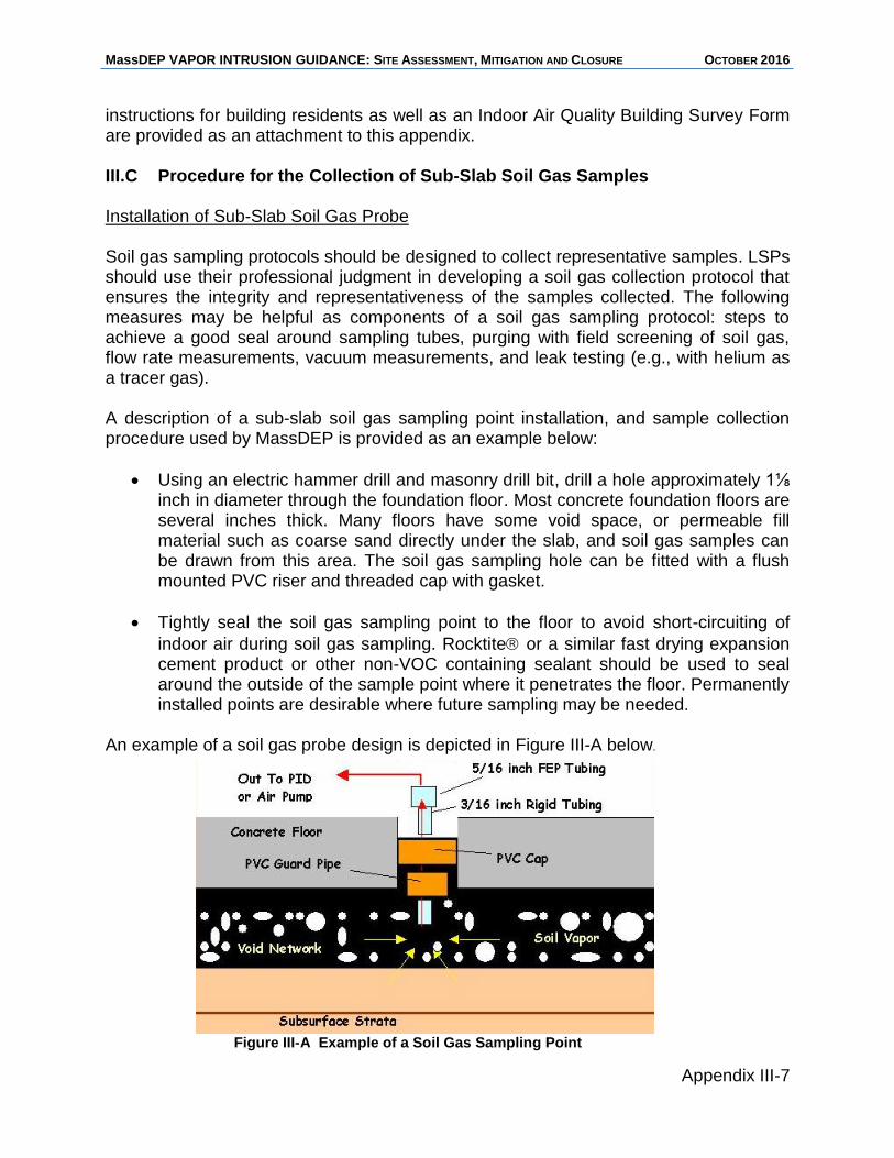
MassDEP VAPOR INTRUSION GUIDANCE: SITE ASSESSMENT, MITIGATION AND CLOSURE OCTOBER 2016
Appendix III-7
instructions for building residents as well as an Indoor Air Quality Building Survey Form are provided as an attachment to this appendix. III.C Procedure for the Collection of Sub-Slab Soil Gas Samples Installation of Sub-Slab Soil Gas Probe Soil gas sampling protocols should be designed to collect representative samples. LSPs should use their professional judgment in developing a soil gas collection protocol that ensures the integrity and representativeness of the samples collected. The following measures may be helpful as components of a soil gas sampling protocol: steps to achieve a good seal around sampling tubes, purging with field screening of soil gas, flow rate measurements, vacuum measurements, and leak testing (e.g., with helium as a tracer gas). A description of a sub-slab soil gas sampling point installation, and sample collection procedure used by MassDEP is provided as an example below:
Using an electric hammer drill and masonry drill bit, drill a hole approximately 1⅛ inch in diameter through the foundation floor. Most concrete foundation floors are several inches thick. Many floors have some void space, or permeable fill material such as coarse sand directly under the slab, and soil gas samples can be drawn from this area. The soil gas sampling hole can be fitted with a flush mounted PVC riser and threaded cap with gasket.
Tightly seal the soil gas sampling point to the floor to avoid short-circuiting of
indoor air during soil gas sampling. Rocktite or a similar fast drying expansion cement product or other non-VOC containing sealant should be used to seal around the outside of the sample point where it penetrates the floor. Permanently installed points are desirable where future sampling may be needed.
An example of a soil gas probe design is depicted in Figure III-A below.
Figure III-A Example of a Soil Gas Sampling Point
MassDEP VAPOR INTRUSION GUIDANCE: SITE ASSESSMENT, MITIGATION AND CLOSURE OCTOBER 2016
Appendix III-8
Sample Collection from the Sub-Slab Point
Sub-slab soil gas points can be sampled using an air pump, evacuated container, or passive absorbent media device. It is usually not necessary to obtain long duration samples when collecting soil gas. Short duration grab samples are sufficient. There is a potential for short-circuiting if a soil gas sample is collected at too high a sampling rate (i.e., much greater than 200 milliliters per minute). Three to five times the volume of the soil gas probe and collection tubing should be purged prior to collecting the sample. Sample collection can be accomplished by placing a rubber stopper, with center hole, in the sampling point. A sampling tube is inserted through the hole in the stopper until it is positioned in the area under the floor to be sampled. Alternatively, the sampling port can contain threaded fittings by which sampling tubes can be attached. Shallow soil gas samples (immediately beneath the slab) are considered more representative than deeper samples because they contain concentrations likely to be entering the building through the cracks in the floor. There is some concern as to whether a building under positive pressure might contribute indoor air to the sub-slab soil gas, thereby diluting or otherwise changing soil vapor concentrations. This potential may be checked by making a pressure measurement at the soil vapor sampling point before collecting a soil vapor sample. Samples may be collected by a variety of methods, including those described in Section III.B.3 of this appendix. Canister sampling is one of the most commonly used methods. When using a canister for sub-slab soil gas sampling, care should be taken to achieve an air-tight connection between the sample inlet line and the soil gas sampling points. A sample inlet line made of chromatographic-grade stainless steel tubing is used to collect a soil gas sample. An air-tight connection must be made between this sample inlet line and the soil vapor sampling point. The canister pressure should be recorded from the vacuum gauge before and after the sampling event. If the glass vial sampling method is used, stagnant air should be evacuated from the soil gas sampling point and sample tubing. A flexible soil gas sample collection tube is inserted into a glass VOA vial, with a septum cap, and the vial is flushed with pumped soil gas for sufficient time to replace the air in the vial with soil gas. The vial is then capped immediately and the sample is obtained for analysis by using a syringe to withdraw an aliquot through the cap septum. III.D Sample Analytical Methods Field Analytical Methods Field analytical methods are advantageous because data can be obtained quickly and the field investigation can be instantly modified to direct sample collection to potential pathways and contaminated areas to enhance the sample density, certainty and representativeness of the assessment. Portable GC or GC/MS instruments can be
MassDEP VAPOR INTRUSION GUIDANCE: SITE ASSESSMENT, MITIGATION AND CLOSURE OCTOBER 2016
Appendix III-9
brought to the site for same day chemical-specific analyses. Real-time methods such as TOV analyzers provide instant reading of air concentrations. Field analytical methods must have a level of method calibration, quality control, and Reporting Limits commensurate with the intended use of the data. Laboratory Analytical Methods Laboratory analytical methods often provide data with a higher level of Quality Assurance and Quality Control than that generated by field analytical methods. There are a variety of laboratory analytical methods available to measure concentrations of contaminants in air. MassDEP recommends the use of the MassDEP’s Compendium of Quality Control Requirements and Performance Standards for Selected Analytical Protocols (MassDEP Policy WSC #10-320, the "CAM"), particularly the TO-15 (WSC-CAM-IX B) and APH (WSC-CAM-IX A) protocols, to evaluate releases of VOCs and light petroleum mixtures in air. The MassDEP CAM specifies the appropriate quality control for these methods. The CAM TO-15 and APH protocols may be found at: http://www.mass.gov/eea/agencies/massdep/cleanup/regulations/wsc10-320-compendium--quality-control-reqs.html.
Analyte List MassDEP strongly recommends use of the full analyte list during the initial stages of site investigations, particularly at sites with an unknown or complicated history of uses of oil or hazardous materials. The use of the full analyte list for a chosen analytical method may not be necessary, however, for sites where available sampling data and substantial site/use history information is available to define the Contaminants of Concern. Under the CAM, the laboratory is required to document and report use of a reduced analyte list on the MassDEP Analytical Protocol Certification Form.
III.E Sample Quality The following sections give a brief description of Data Quality Objectives and Sample Quality Assurance and Quality Control. More detailed information on these topics can be found in the MassDEP CAM documents. Data Quality Objectives Data quality objectives are sampling goals which must be met to ensure that the data obtained will be of sufficient quality for characterizing conditions, supporting evaluations and making decisions about response actions at the site. Factors to consider in setting data quality objectives are: precision, accuracy, representativeness, comparability, completeness and sensitivity. These indicators are used together with data quality control measurements to define the quality of the data collected. More detailed data quality information is provided in the MassDEP CAM documents and Policy #WSC-07-350, MCP Representativeness and Data Usability Assessments.
MassDEP VAPOR INTRUSION GUIDANCE: SITE ASSESSMENT, MITIGATION AND CLOSURE OCTOBER 2016
Appendix III-10
Sample Quality Assurance and Quality Control (QA/QC) In order to monitor the quality of indoor air results, QA/QC techniques should be routinely incorporated into air sampling and analysis activities. QA activities include planning, implementing, documenting, assessing and reporting that assure that data are of known and documented quality. QC activities are measures that assess whether and how well the goals established in the quality assurance components were met. Detailed QA/QC information is specified in MassDEP’s CAM documents.
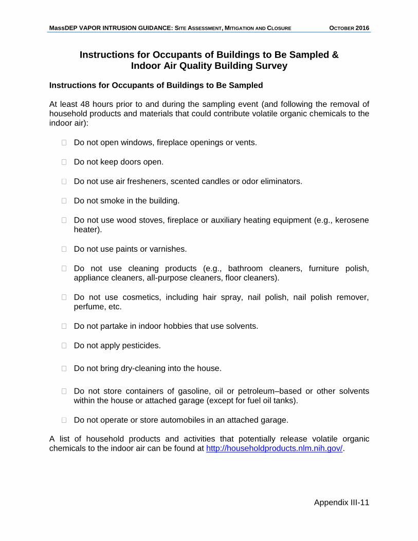
MassDEP VAPOR INTRUSION GUIDANCE: SITE ASSESSMENT, MITIGATION AND CLOSURE OCTOBER 2016
Appendix III-11
Instructions for Occupants of Buildings to Be Sampled & Indoor Air Quality Building Survey
Instructions for Occupants of Buildings to Be Sampled At least 48 hours prior to and during the sampling event (and following the removal of household products and materials that could contribute volatile organic chemicals to the indoor air):
Do not open windows, fireplace openings or vents.
Do not keep doors open.
Do not use air fresheners, scented candles or odor eliminators.
Do not smoke in the building.
Do not use wood stoves, fireplace or auxiliary heating equipment (e.g., kerosene heater).
Do not use paints or varnishes.
Do not use cleaning products (e.g., bathroom cleaners, furniture polish, appliance cleaners, all-purpose cleaners, floor cleaners).
Do not use cosmetics, including hair spray, nail polish, nail polish remover, perfume, etc.
Do not partake in indoor hobbies that use solvents.
Do not apply pesticides.
Do not bring dry-cleaning into the house.
Do not store containers of gasoline, oil or petroleum–based or other solvents within the house or attached garage (except for fuel oil tanks).
Do not operate or store automobiles in an attached garage. A list of household products and activities that potentially release volatile organic chemicals to the indoor air can be found at http://householdproducts.nlm.nih.gov/.
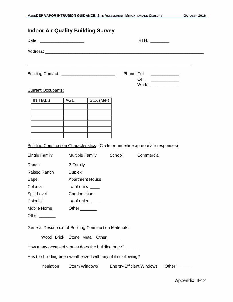
MassDEP VAPOR INTRUSION GUIDANCE: SITE ASSESSMENT, MITIGATION AND CLOSURE OCTOBER 2016
Appendix III-12
Indoor Air Quality Building Survey
Date: ___________________ RTN: ________
Address: ____________________________________________________________________
______________________________________________________________________
Building Contact: _______________________ Phone: Tel: ____________
Cell: ____________
Work: ____________
Current Occupants:
INITIALS AGE SEX (M/F)
Building Construction Characteristics: (Circle or underline appropriate responses) Single Family Multiple Family School Commercial Ranch 2-Family
Raised Ranch Duplex
Cape Apartment House
Colonial # of units ____
Split Level Condominium
Colonial # of units ____
Mobile Home Other _______
Other _______
General Description of Building Construction Materials:
Wood Brick Stone Metal Other______ How many occupied stories does the building have? _____ Has the building been weatherized with any of the following?
Insulation Storm Windows Energy-Efficient Windows Other ______
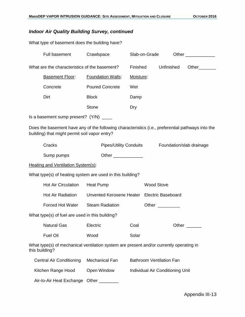
MassDEP VAPOR INTRUSION GUIDANCE: SITE ASSESSMENT, MITIGATION AND CLOSURE OCTOBER 2016
Appendix III-13
Indoor Air Quality Building Survey, continued
What type of basement does the building have?
Full basement Crawlspace Slab-on-Grade Other ____________
What are the characteristics of the basement? Finished Unfinished Other_______
Basement Floor: Foundation Walls: Moisture: Concrete Poured Concrete Wet Dirt Block Damp Stone Dry
Is a basement sump present? (Y/N) ____
Does the basement have any of the following characteristics (i.e., preferential pathways into the
building) that might permit soil vapor entry?
Cracks Pipes/Utility Conduits Foundation/slab drainage Sump pumps Other ____________
Heating and Ventilation System(s):
What type(s) of heating system are used in this building? Hot Air Circulation Heat Pump Wood Stove Hot Air Radiation Unvented Kerosene Heater Electric Baseboard Forced Hot Water Steam Radiation Other _________
What type(s) of fuel are used in this building?
Natural Gas Electric Coal Other ______ Fuel Oil Wood Solar
What type(s) of mechanical ventilation system are present and/or currently operating in this building?
Central Air Conditioning Mechanical Fan Bathroom Ventilation Fan Kitchen Range Hood Open Window Individual Air Conditioning Unit Air-to-Air Heat Exchange Other ________
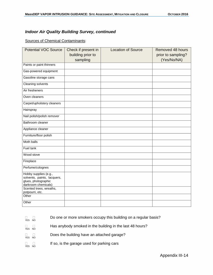
MassDEP VAPOR INTRUSION GUIDANCE: SITE ASSESSMENT, MITIGATION AND CLOSURE OCTOBER 2016
Appendix III-14
Indoor Air Quality Building Survey, continued Sources of Chemical Contaminants:
Potential VOC Source Check if present in
building prior to
sampling
Location of Source Removed 48 hours
prior to sampling?
(Yes/No/NA)
Paints or paint thinners
Gas-powered equipment
Gasoline storage cans
Cleaning solvents
Air fresheners
Oven cleaners
Carpet/upholstery cleaners
Hairspray
Nail polish/polish remover
Bathroom cleaner
Appliance cleaner
Furniture/floor polish
Moth balls
Fuel tank
Wood stove
Fireplace
Perfume/colognes
Hobby supplies (e.g., solvents, paints, lacquers, glues, photographic darkroom chemicals)
Scented trees, wreaths, potpourri, etc.
Other
Other
Do one or more smokers occupy this building on a regular basis? YES NO
Has anybody smoked in the building in the last 48 hours? YES NO
Does the building have an attached garage? YES NO
If so, is the garage used for parking cars YES NO
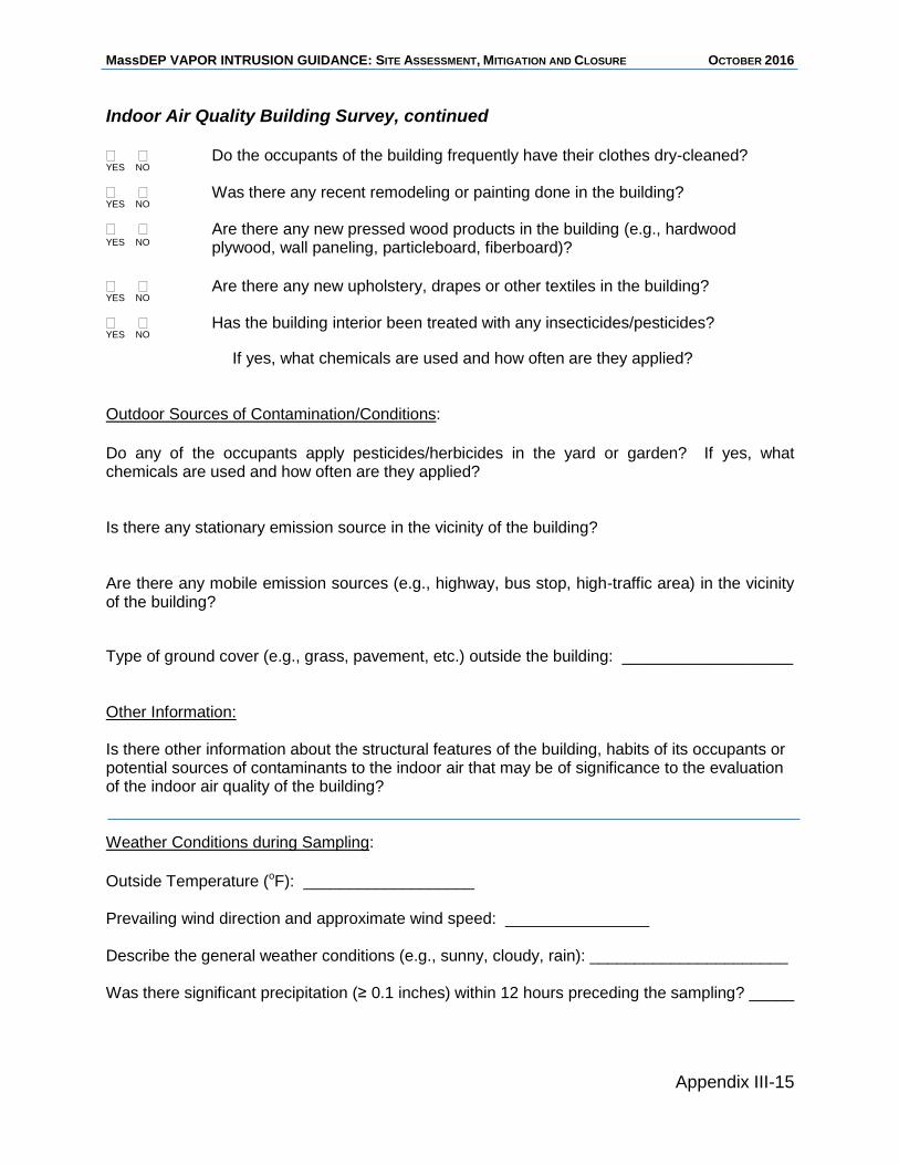
MassDEP VAPOR INTRUSION GUIDANCE: SITE ASSESSMENT, MITIGATION AND CLOSURE OCTOBER 2016
Appendix III-15
Indoor Air Quality Building Survey, continued
Do the occupants of the building frequently have their clothes dry-cleaned? YES NO
Was there any recent remodeling or painting done in the building? YES NO
Are there any new pressed wood products in the building (e.g., hardwood YES NO plywood, wall paneling, particleboard, fiberboard)?
Are there any new upholstery, drapes or other textiles in the building? YES NO
Has the building interior been treated with any insecticides/pesticides? YES NO
If yes, what chemicals are used and how often are they applied? Outdoor Sources of Contamination/Conditions:
Do any of the occupants apply pesticides/herbicides in the yard or garden? If yes, what chemicals are used and how often are they applied? Is there any stationary emission source in the vicinity of the building? Are there any mobile emission sources (e.g., highway, bus stop, high-traffic area) in the vicinity of the building?
Type of ground cover (e.g., grass, pavement, etc.) outside the building: ___________________ Other Information: Is there other information about the structural features of the building, habits of its occupants or potential sources of contaminants to the indoor air that may be of significance to the evaluation of the indoor air quality of the building? Weather Conditions during Sampling:
Outside Temperature (oF): ___________________ Prevailing wind direction and approximate wind speed: ________________ Describe the general weather conditions (e.g., sunny, cloudy, rain): ______________________ Was there significant precipitation (≥ 0.1 inches) within 12 hours preceding the sampling? _____

MassDEP VAPOR INTRUSION GUIDANCE: SITE ASSESSMENT, MITIGATION AND CLOSURE OCTOBER 2016
Appendix III-16
MassDEP VAPOR INTRUSION GUIDANCE: SITE ASSESSMENT, MITIGATION AND CLOSURE OCTOBER 2016
Appendix IV
MassDEP’s Recommended Specifications for the Design and Construction of SSD Systems

MassDEP VAPOR INTRUSION GUIDANCE: SITE ASSESSMENT, MITIGATION AND CLOSURE OCTOBER 2016
MassDEP VAPOR INTRUSION GUIDANCE: SITE ASSESSMENT, MITIGATION AND CLOSURE OCTOBER 2016
Appendix IV-1
Appendix IV – MassDEP’s Recommended Specifications for the Design and Construction of SSD Systems
1.0 GENERAL PERFORMANCE STANDARDS
1.1. All materials and techniques should comply with or exceed industry standards and/or normal practices and conform to applicable provisions of this document.
1.2. All system components should be installed in a professional and competent manner, minimizing inconvenience to building occupants.
1.3. All reasonable steps should be taken to minimize disturbance of floor coverings, plaster/sheetrock walls and ceilings, exterior walls and sidings, and other building components and accessories.
1.4. All disturbed area should be restored to a “broom clean” standard.
1.5. All work must be conducted in compliance with all applicable mechanical, electrical, building, plumbing, energy and fire prevention codes.
2.0 SEQUENCE OF ACTIVITIES
2.1. Document the pre-construction condition of the structure and other pertinent features of the areas that will be subject to construction, along with areas needed to access and egress from the work areas, for the purpose of comparing the pre-construction conditions to the post-construction conditions and determining if claims of damage are valid or the result of pre-existing conditions. The documentation should include photographs of walls, floor, contents, and any other features that could be affected, as well as notes regarding any existing conditions that may be pertinent for comparing pre-construction and post-construction conditions.
2.2. Repair concrete floors, seal cracks, seal or fit floor drains with a Dranjer device, install and/or seal sumps and/or address any other items specific to the site.
2.3. Perform a Sub-slab Communication Diagnostic Test. In the event that a sufficient negative pressure field cannot be demonstrated on the basis of a single Extraction Hole, perform an additional Sub-slab Communication Diagnostic Test in a second location.
2.4. Install the SSDS.
2.5. Activate the system and measure extraction and sub-slab pressures.
2.6. Conduct a back-drafting evaluation, if such an evaluation is warranted due to the presence of natural-draft combustion appliances.
2.7. Affix labels to system components.
3.0 PRE-SYSTEM SITE PREPARATION
3.1. Missing/incompetent concrete
3.1.1. Voids in the basement slab should be filled with compacted gravel as needed and brought to surrounding grade via the placement of a minimum of 3 inches of standard concrete (minimum compressive strength of 3000 PSI).
3.1.2. Incompetent concrete should be removed and replaced with new concrete.
MassDEP VAPOR INTRUSION GUIDANCE: SITE ASSESSMENT, MITIGATION AND CLOSURE OCTOBER 2016
Appendix IV-2
3.2. Cracks and joints that require sealing
3.2.1. Ensure that surfaces to be sealed are clean, dry, and free of soil, decomposed concrete, dust, grease, and debris.
3.2.2. Cracks and joints up to 1/8th inch (0.125”) in width and depth should be sealed with a urethane-based product, epoxy, or other suitable non-cementitious sealant in accordance with the manufacturer’s instructions. All sealants must be specifically designed for use on concrete and should conform to the Chemical Constituent Standard specified in Section 10.0.
3.2.3. Cracks and joints larger than 1/8th inch (0.125”) should be either (i) sealed in accordance
with the provisions of Section 7.2.2, utilizing a foam backer rod or other comparable filler material as per the manufacturer’s instruction; and/or (ii) filled with non-shrinking cementitious material.
3.3. Sump(s)
3.3.1. Inactive/Unnecessary Sumps – Sumps that are not or no longer needed in a structure should be filled with gravel and concrete.
3.3.2. Active/Needed Sumps - Drainage sumps in active/continuing use should be modified, retro-fitted, or removed and replaced in their entirety to ensure that they do not provide a pathway for vapor intrusion. New systems should conform to the following:
3.3.2.1. The basin and lid unit should be constructed of durable plastic or other rigid material that produces an air-tight seal.
3.3.2.2. Concrete and/or soil materials should be removed as needed to facilitate the installation of the new basin and/or lid. The unit should be surrounded by crushed stone, and any existing sub-slab water collection pipes must be tied into the basin. The slab annular space should be filled with concrete and/or hydraulic cement/grout, ensuring that the cover is set flush with the floor surface.
3.3.2.3. If a sump pump is present, the lid must be easily removable by the owner/occupants of the building. Electrical wiring and water ejection piping penetrating the lid should be made airtight by the use of grommets and/or sealants. A check valve or water trap should be installed on the sump drain/ejection piping to prevent short-circuiting of the SSD system.
3.4. Floor Drains.
3.4.1. Inactive floor drains should be sealed with hydraulic cement/grout.
3.4.2. Active floor drains should be fitted with an appropriate Dranjer-like insert, with grout/sealant added as needed around the annular space to ensure air-tight conditions.
4.0 SUB-SLAB COMMUNICATION DIAGNOSTIC TEST A Sub-slab Communication Diagnostic Test should be conducted for each SSD system to determine the airflow characteristics of the material(s) beneath the building slab, determine the number of Extraction
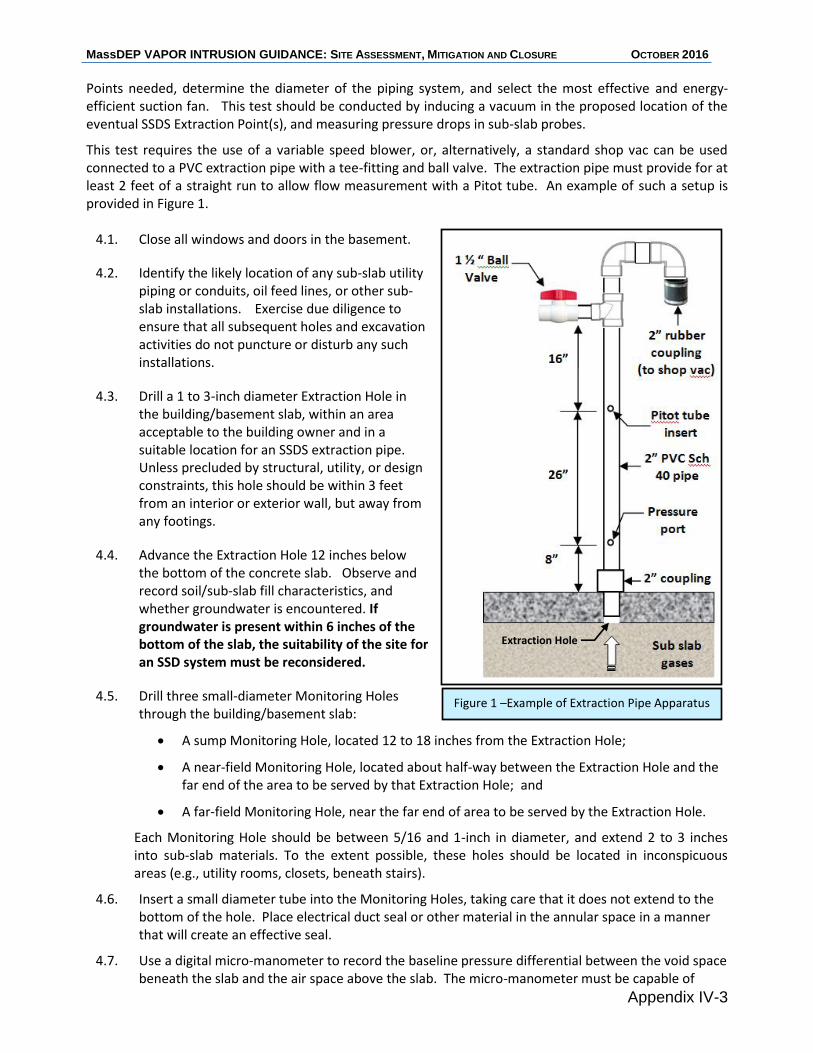
MassDEP VAPOR INTRUSION GUIDANCE: SITE ASSESSMENT, MITIGATION AND CLOSURE OCTOBER 2016
Appendix IV-3
Points needed, determine the diameter of the piping system, and select the most effective and energy-efficient suction fan. This test should be conducted by inducing a vacuum in the proposed location of the eventual SSDS Extraction Point(s), and measuring pressure drops in sub-slab probes.
This test requires the use of a variable speed blower, or, alternatively, a standard shop vac can be used connected to a PVC extraction pipe with a tee-fitting and ball valve. The extraction pipe must provide for at least 2 feet of a straight run to allow flow measurement with a Pitot tube. An example of such a setup is provided in Figure 1.
4.1. Close all windows and doors in the basement.
4.2. Identify the likely location of any sub-slab utility piping or conduits, oil feed lines, or other sub-slab installations. Exercise due diligence to ensure that all subsequent holes and excavation activities do not puncture or disturb any such installations.
4.3. Drill a 1 to 3-inch diameter Extraction Hole in the building/basement slab, within an area acceptable to the building owner and in a suitable location for an SSDS extraction pipe. Unless precluded by structural, utility, or design constraints, this hole should be within 3 feet from an interior or exterior wall, but away from any footings.
4.4. Advance the Extraction Hole 12 inches below the bottom of the concrete slab. Observe and record soil/sub-slab fill characteristics, and whether groundwater is encountered. If groundwater is present within 6 inches of the bottom of the slab, the suitability of the site for an SSD system must be reconsidered.
4.5. Drill three small-diameter Monitoring Holes through the building/basement slab:
A sump Monitoring Hole, located 12 to 18 inches from the Extraction Hole;
A near-field Monitoring Hole, located about half-way between the Extraction Hole and the far end of the area to be served by that Extraction Hole; and
A far-field Monitoring Hole, near the far end of area to be served by the Extraction Hole.
Each Monitoring Hole should be between 5/16 and 1-inch in diameter, and extend 2 to 3 inches into sub-slab materials. To the extent possible, these holes should be located in inconspicuous areas (e.g., utility rooms, closets, beneath stairs).
4.6. Insert a small diameter tube into the Monitoring Holes, taking care that it does not extend to the bottom of the hole. Place electrical duct seal or other material in the annular space in a manner that will create an effective seal.
4.7. Use a digital micro-manometer to record the baseline pressure differential between the void space beneath the slab and the air space above the slab. The micro-manometer must be capable of
Figure 1 –Example of Extraction Pipe Apparatus
Extraction Hole
MassDEP VAPOR INTRUSION GUIDANCE: SITE ASSESSMENT, MITIGATION AND CLOSURE OCTOBER 2016
Appendix IV-4
detecting and quantifying a pressure differential of > 0.002 inches of water column (w.c.).
4.8. Insert a 1-3 inch diameter PVC extraction pipe into the Extraction Hole (see Figure 1). Apply electrical duct seal or other suitable material in the annular space around the extraction pipe in a manner that will create an effective seal. The extraction pipe should include a fitting to allow measurement of vacuum using a magnehelic gauge, and a small hole in a section of straight piping to allow the insertion of a Pitot tube in accordance with standard practices and recommendations. Connect the extraction pipe to a shop vac or other vacuum blower that can achieve 40 to 50+ inches water column (w.c.) of negative pressure. Close any air bleed valve on the extraction pipe. Ensure that the discharge from the show vac/blower is piped outdoors.
4.9. Activate the blower and record the negative pressure at the fitting on the extraction pipe. Then measure and record the pressure differential in the Monitoring Holes using the digital micro-manometer, waiting at least 2 minutes if tight soil conditions are suspected and/or if less than -0.020 inches of w.c. is initially observed. Measure the flowrate through the extraction pipe using a Pitot tube.
4.10. If the vacuum at the sump Monitoring Hole (i.e., 12 to 18 inches from the Extraction Hole) is higher than the vacuum of the suction fan that will be used in the final SSD system (i.e. typically 1 to 4 inches w.c. of negative pressure), reduce the vacuum applied to the Extraction Hole (e.g., by opening the air bleed ball valve) until the negative pressure in the sump Monitoring Hole is within the vacuum range of the anticipated suction fan. Then measure and record negative pressures in the near-field and far-field sub-slab probes, and flowrate in the extraction pipe.
Optionally, consider conducting a more robust “pump test” by obtaining a series of pressure/flow data points to produce a (subslab) system resistance curve, which can then be compared to available fans to select a fan with optimum energy efficiency. The desired negative pressure readings in the near-field and far-field Monitoring Holes are a minimum of:
0.012 inches of w.c. during winter conditions (November 1st through March 31st); or
0.020 inches of w.c. during non-winter conditions (April 1st through October 31st)
4.11. It is not necessary to achieve the above cited negative pressure values in cases where sub-slab conditions are highly pervious and/or transmissive, as demonstrated by (i) visual observations of sub-slab materials during the drilling of the Extraction and Monitoring Holes, and (ii) high flowrates observed during diagnostic testing. In these cases, an adequate negative pressure field could be demonstrated and documented if smoke testing at the Monitoring Holes indicates a strong downward movement of smoke into the Monitoring Holes/Sub-slab.
4.12. In buildings where an adequate negative pressure field in not documented using one Extraction Hole, a second Sub-slab Communication Diagnostic Test should be conducted in another area of the structure, following the procedures articulated in Sections 4.1 through 4.11. In the event that the second Sub-slab Communication Diagnostic Test does not document the establishment of an adequate negative pressure field beneath the footprint of the structure, additional steps and measures should be considered, including:
additional sealing of cracks and void spaces;
additional diagnostic testing under worst-case building depressurization conditions (i.e., running all fans and combustion appliances), to determine if the negative pressure field
MassDEP VAPOR INTRUSION GUIDANCE: SITE ASSESSMENT, MITIGATION AND CLOSURE OCTOBER 2016
Appendix IV-5
under worst-case conditions is at least 0.004 inches of w.c.; and/or
the use of high pressure/low flow fans (capable of producing a vacuum of 20 to 50 inches of w.c.).
5.0 SYSTEM DESIGN AND INSTALLATION
5.1. General
A depiction of key system components is provided in Figure 2.
5.2. Suction Fan
5.2.1. The suction fan selected for the SSD system should:
produce an adequate sub-slab negative pressure field under all areas of interest
consume the lowest amount of electrical power (watts) needed to achieve the necessary negative pressure field
operate with a minimum amount of operational noise and vibration
be designed specifically for radon or sub-slab depressurization system (SSDS) applications;
be UL listed and rated for continuous, all-weather operations, with thermal overload with automatic reset features in the event of a power failure;
be contained in a durable, weatherproof, UV resistant housing, installed with removable couplings or flexible connections, mounted and secured in a manner that minimizes the transfer of vibrations to the structure;
be hard-wired into the building power supply, incorporating an on/off or disconnect switch consistent with applicable electrical and building codes; and
have a minimum 5-year manufacturer’s warranty.
5.2.2. The suction fan unit will generally be installed on the outside of the building, level and plumb, in a manner compliant with the manufacturer’s recommendations, in a location permitted by the building owner. Unless precluded by site-specific grading/conditions, the fan unit should be located between 3 and 5 feet above ground level; high enough to be above any snow accumulations, low enough for easy observation and maintenance.
5.2.3. Except were precluded by difficult (“tight”) subsurface conditions, the selected fan should require less than 90 watts of power at its system operating point, and ensure that flow velocities in the extraction piping are less than 1000 to 1500 feet/minute (to avoid noise).
5.2.4. The suction fan should be equipped with an integral condensate by-pass and/or should be equipped with bypass tubing.
5.3. Extraction Point(s)
5.3.1. Unless precluded by site-specific conditions, the Extraction Point(s) should generally be installed in the same location(s) as the Extraction Hole(s) used during the Sub-Slab Communication Diagnostic Test(s).
5.3.2. For most typical systems, a coring drill with a 5 to 6 inch diameter core bit should be used to create a cylindrical hole through the concrete slab.
MassDEP VAPOR INTRUSION GUIDANCE: SITE ASSESSMENT, MITIGATION AND CLOSURE OCTOBER 2016
Appendix IV-6
5.3.3. It is very important that sub-slab materials be removed to create a suction pit void space.
5.3.3.1. The depth of the pit should be at least 12 inches, with a diameter of (i) 12 inches if coarse sub-slab materials are encountered, or (ii) 18 inches if tight sub-slab materials are encountered.
5.3.3.2. The suction pit space may remained unfilled if (i) groundwater is not present, and (ii) the overlying and surrounding concrete slab is at least 3 inches thick and structurally sound. Otherwise, or at the discretion of the installer, the void space should be filled with ¾ inch to 1¼ inch crushed stone that is free of fines. A PVC pipe should be inserted through the cylindrical core to the bottom of the concrete slab, but should not contact the crushed stone, if present. The pipe must be supported in a manner that will permanently prevent downward movement.
5.3.3.3. A gasket or backer rod should be placed in the gap space between the PVC pipe and the concrete slab, and this annular space should be sealed with a urethane-based sealant. If necessary, large gaps should first be filled with a non-shrinking hydraulic cement/grout, followed by the application of the urethane sealant once the hydraulic cement/grout has cured.
5.4. Piping
5.4.1. Piping should conform to local and applicable building and plumbing codes.
5.4.2. All system piping should consist of Schedule 40 PVC, with treaded or solvent-welded connections consistent with manufacturer specifications. Primer and cements used in solvent-welded connections should have low VOC content and low toxicity.
5.4.3. Generally, the PVC piping should be a minimum of 3-inches in inner diameter when the projected system flowrate is less than 50 CFM, and a minimum of 4-inches in inner diameter when the projected system flowrate is equal to or greater than 50 CFM (due to increase head loss at higher flowrate that will lead to excessive energy use and electricity costs).
5.4.4. In order to minimize head loss, the interior of all PVC piping and fittings should be smooth and burr-free. “Long Sweep” fittings are preferred unless their use is precluded by space or logistical constraints.
5.4.5. Piping must not block access to building areas requiring maintenance or inspection.
5.4.6. All horizontal-piping runs should be installed at a minimum slope of 1/8 inch per foot back toward the Extraction Point(s) in order to drain all condensate/precipitation back to the Extraction Point(s).
5.4.7. All piping within the building space must be under negative pressure. All pressurized piping runs must be made exterior to the building.
5.4.8. The suction fan discharge pipe should be routed up an exterior wall, to a point 2 feet above the roofline. The termination point should be at least 10 feet above grade, and at least 10 feet from any window, door, operable roof window, air intake, or adjacent building. A pipe (“critter”) guard should be installed at the termination point to keep leaves, debris, and animals out of the system.
5.4.9. Horizontal and vertical piping should be supported at a frequency and in a manner required by applicable building or plumbing codes. At a minimum, horizontal runs should be supported every 6 feet and vertical runs shall be supported every 8 feet.
5.4.10. Routing of piping must be done in a manner that does not compromise the structural
MassDEP VAPOR INTRUSION GUIDANCE: SITE ASSESSMENT, MITIGATION AND CLOSURE OCTOBER 2016
Appendix IV-7
integrity of the building. Penetrations of joists or beams shall be done only in strict compliance with applicable plumbing and building codes. All penetrations between discrete building spaces and exterior walls should be sealed by application of an expanding foam product or appropriate sealant within the penetration annular space.
5.4.11. In systems where more than one extraction point is installed, each Extraction Point (“leg”) should incorporate a PVC ball valve to control and balance system operation.
5.5. Sampling Ports
5.5.1. At least one sampling port should be installed outside the building on piping under positive pressure, just downstream of the fan.
5.5.2. Sampling ports should be brass or nylon threaded 3/16th-inch O.D. hose barbs installed into the PVC piping via drilling and tapping, using sealants if necessary to produce an airtight and long-lasting connection. The hose barb should be equipped with a cap and/or stopcock to prevent leakage in or out of the PVC piping when sampling is not being conducted.
5.6. Electrical
5.6.1. All wiring should be conducted by a Licensed Massachusetts Electrician, in accordance with all applicable provisions of the National Electric Code and any additional local requirements.
5.6.2. All suction fans should be hard wired into a dedicated 120 VAC 15 amp house circuit which should be labeled as “Radon Fan”.
5.6.3. Wiring should not be located in or chased through system piping or heating or cooling ductwork. All penetrations between discrete building spaces and exterior walls should be sealed by application of an expanding foam product or appropriate sealant within the penetration annular space.
5.7. Continuous Vacuum Monitor
5.7.1. All SSD systems should include a manometer in the vertical run of each Extraction Point in a location that can be easily monitored by building occupants.
5.7.2. The acceptable vacuum range of the system (i.e., to ensure mitigation of vapor intrusion) should be clearly marked on each installed manometer.
5.8. Alarms
5.8.1. It is recommended that SSD systems include a visual and audible alarm that activates when a loss of vacuum and/or substantial reduction in flow occurs. The audible element in the system alarm should be no less than 85 decibels at a distance of 1 foot.
5.8.2. It is highly recommended that a carbon monoxide detector be installed or present in any home where natural-draft combustion furnaces/boilers or appliances are present. In basements that include one or more sleeping areas, the carbon monoxide detector should be placed within 10 feet of a bedroom door.
5.9. Permanent Sub-Slab Monitoring Probes
5.9.1. At least two permanent sub-slab monitoring probes should be installed to permit long-term monitoring of pressure fields and sub-slab soil vapor constituents. One probe should be in the far end of the pressure field.
MassDEP VAPOR INTRUSION GUIDANCE: SITE ASSESSMENT, MITIGATION AND CLOSURE OCTOBER 2016
Appendix IV-8
5.9.2. Generally, permanent probes should be installed in the same holes used to construct temporary monitoring points during the diagnostic phase. Any temporary Monitoring Holes not converted to permanent monitoring points should be filled in with hydraulic cement/grout.
5.9.3. Monitoring probes should be placed in unobtrusive areas to the extent practicable, in locations acceptable to the building owner.
5.9.4. Monitoring probes should be constructed in a manner to ensure good communication with the underlying sub-slab environment and be sealed with expanding cement or other material to prevent movement of air in the annular space.
5.9.5. Monitoring probes should be recessed below the level of the floor and covered with a removable cap
6.0 CHEMICAL CONSTITUENTS IN SSDS MATERIALS
6.1. Products used to seal concrete cracks and void spaces should contain less than 100 grams/Liter of VOCs, as described and specified in Rule #1168 of the South Coast Air Quality Management District (SCAQMD).
6.2. Glues and cleaners used to join PVC piping should contain less than 510 grams/Liter of VOCs, as described and specified in Rule #1168 of the South Coast Air Quality Management District (SCAQMD).
6.3. Sealants, glues, cleaners, expanding foams and all other chemical products used in the site preparation and SSDS installation process should not contain constituents that are known to cause developmental impacts, as specified in the California Safe Drinking Water and Toxic Enforcement Act of 1986 (Proposition 65).
7.0 SYSTEM START-UP AND OPTIMIZATION
7.1. The installer should activate the system, and observe operations for at least 30 minutes. All system components should be inspected.
7.2. The vacuum in the system manometer(s) should be checked to ensure proper operation. A digital micro-manometer should then be used to measure pressure differential at each of the permanent sub-slab monitoring points, to verify that appropriate negative pressures have been achieved
8.0 BACK-DRAFTING EVALUATION
8.1. In building with natural-draft combustion furnaces/boiler or appliances, a back-drafting evaluation should be considered once the SSD system has achieved steady-state operation. This evaluation should be conducted in accordance with procedures specified in the USEPA Radon Mitigation Standard, as reproduced below:
i. Close all windows and doors, both external and internal.
ii. Open all HVAC supply and return air duct vents/registers.
iii. Close fireplace and wood stove dampers.
iv. Turn on all exhaust and air distribution fans and combustion appliances EXCEPT the appliance being tested for backdrafting.
MassDEP VAPOR INTRUSION GUIDANCE: SITE ASSESSMENT, MITIGATION AND CLOSURE OCTOBER 2016
Appendix IV-9
v. Wait 5 minutes.
vi. Test to determine the indoor-outdoor pressure differential in the room where the appliance being tested is located. If the pressure differential is a negative 5 Pascals or more, assume that a potential for backdrafting exists.
vii. To begin a test for actual spillage of flue gases, turn on the appliance being tested. (If the appliance is a forced air furnace, ensure that the blower starts to run before proceeding.)
viii. Wait 5 minutes.
ix. Using either a smoke tube or a carbon dioxide gas analyzer, check for flue gas spillage near the vent hood.
x. Repeat steps iv through ix for each natural draft combustion appliance being tested for backdrafting. Seasonal and extreme weather conditions should be considered when evaluating pressure differentials and the potential for backdrafting.
8.2. If spillage is confirmed from any natural draft combustion appliance, the SSD system should be immediately shut down, and not returned to service back-drafting problems are corrected.
9.0 LABELS
9.1. Labels should be used to clearly mark the Extraction Point riser pipe(s), manometer(s), alarm, fan on/off switch, and the fan circuit breaker or fuse in the electrical panel. The use of “Radon” labels are acceptable, as they are readily available, and are more likely to be understood by building occupants (i.e., as opposed to an “SSDS” label)
9.2. Markings should also be made on or next to the system manometer(s) on the Extraction Points to clearly indicate the acceptable operating range. This range should consider normal fluctuations based upon system age and meteorological conditions, but should have as the lower limit the minimum amount of vacuum required to maintain a negative pressure field beneath the structure, and as an upper limit a reading that is likely to indicate significant system or site modification or distress (e.g., high groundwater table).
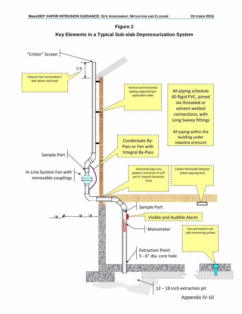
MassDEP VAPOR INTRUSION GUIDANCE: SITE ASSESSMENT, MITIGATION AND CLOSURE OCTOBER 2016
Appendix IV-10
Figure 2
Key Elements in a Typical Sub-slab Depressurization System
12 – 18 inch extraction pit
“Critter” Screen
In-Line Suction Fan with removable couplings
2 ft.
Extraction Point 5 - 6” dia. core hole
Manometer
Sample Port
Exhaust riser terminated 2 feet above roof level
Vertical and horizontal piping supported per
applicable codes
Horizontal pipe runs sloped a minimum of 1/8” per ft. toward Extraction
Point
Two permanent sub-slab monitoring probes
All piping schedule 40 Rigid PVC, joined
via threaded or solvent welded
connections, with Long Sweep fittings
All piping within the building under
negative pressure
Visible and Audible Alarm
Condensate By-Pass or Fan with Integral By-Pass
Carbon Monoxide Detector (when appropriate)
Sample Port
MassDEP VAPOR INTRUSION GUIDANCE: SITE ASSESSMENT, MITIGATION AND CLOSURE OCTOBER 2016
Appendix IV-11
Recommended Report Format
Sub-slab Depressurization System Completion Report
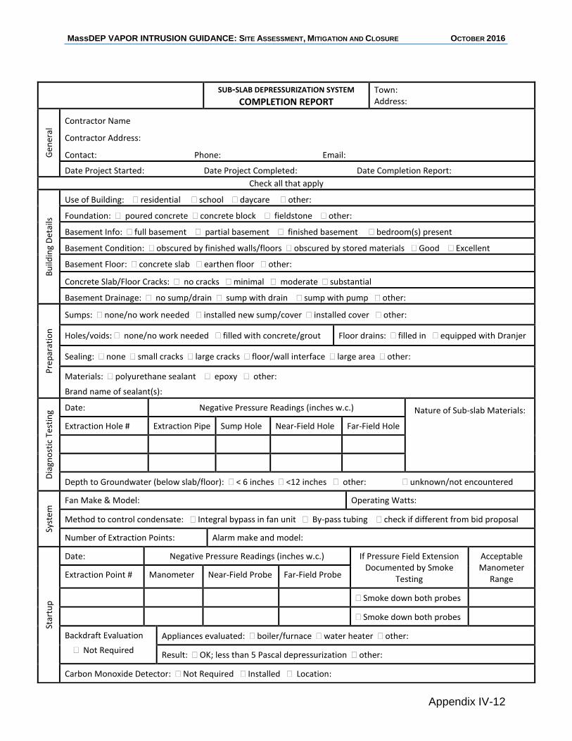
MassDEP VAPOR INTRUSION GUIDANCE: SITE ASSESSMENT, MITIGATION AND CLOSURE OCTOBER 2016
Appendix IV-12
SUB-SLAB DEPRESSURIZATION SYSTEM
COMPLETION REPORT
Town: Address:
Gen
eral
Contractor Name
Contractor Address:
Contact: Phone: Email:
Date Project Started: Date Project Completed: Date Completion Report:
Check all that apply
Bu
ildin
g D
etai
ls
Use of Building: residential school daycare other:
Foundation: poured concrete concrete block fieldstone other:
Basement Info: full basement partial basement finished basement bedroom(s) present
Basement Condition: obscured by finished walls/floors obscured by stored materials Good Excellent
Basement Floor: concrete slab earthen floor other:
Concrete Slab/Floor Cracks: no cracks minimal moderate substantial
Basement Drainage: no sump/drain sump with drain sump with pump other:
Pre
par
atio
n
Sumps: none/no work needed installed new sump/cover installed cover other:
Holes/voids: none/no work needed filled with concrete/grout Floor drains: filled in equipped with Dranjer
Sealing: none small cracks large cracks floor/wall interface large area other:
Materials: polyurethane sealant epoxy other:
Brand name of sealant(s):
Dia
gno
stic
Te
stin
g Date: Negative Pressure Readings (inches w.c.) Nature of Sub-slab Materials:
Extraction Hole # Extraction Pipe Sump Hole Near-Field Hole Far-Field Hole
Depth to Groundwater (below slab/floor): < 6 inches <12 inches other: unknown/not encountered
Syst
em
Fan Make & Model: Operating Watts:
Method to control condensate: Integral bypass in fan unit By-pass tubing check if different from bid proposal
Number of Extraction Points: Alarm make and model:
Star
tup
Date: Negative Pressure Readings (inches w.c.) If Pressure Field Extension Documented by Smoke
Testing
Acceptable Manometer
Range Extraction Point # Manometer Near-Field Probe Far-Field Probe
Smoke down both probes
Smoke down both probes
Backdraft Evaluation
Not Required
Appliances evaluated: boiler/furnace water heater other:
Result: OK; less than 5 Pascal depressurization other:
Carbon Monoxide Detector: Not Required Installed Location:
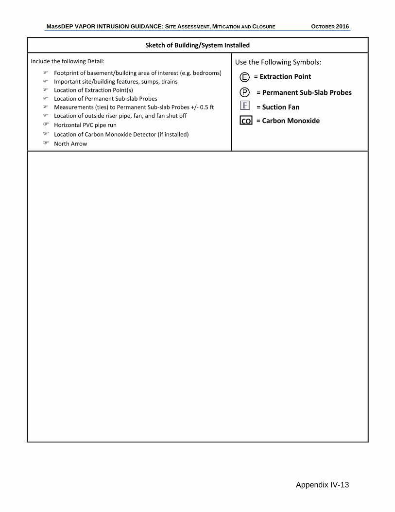
MassDEP VAPOR INTRUSION GUIDANCE: SITE ASSESSMENT, MITIGATION AND CLOSURE OCTOBER 2016
Appendix IV-13
Sketch of Building/System Installed
Include the following Detail:
Footprint of basement/building area of interest (e.g. bedrooms)
Important site/building features, sumps, drains
Location of Extraction Point(s)
Location of Permanent Sub-slab Probes
Measurements (ties) to Permanent Sub-slab Probes +/- 0.5 ft
Location of outside riser pipe, fan, and fan shut off
Horizontal PVC pipe run Location of Carbon Monoxide Detector (if installed) North Arrow
Use the Following Symbols:
CO
= Extraction Point
= Permanent Sub-Slab Probes
= Suction Fan
= Carbon Monoxide Detector
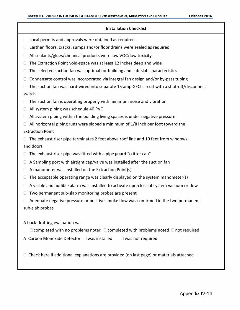
MassDEP VAPOR INTRUSION GUIDANCE: SITE ASSESSMENT, MITIGATION AND CLOSURE OCTOBER 2016
Appendix IV-14
Installation Checklist
Local permits and approvals were obtained as required
Earthen floors, cracks, sumps and/or floor drains were sealed as required
All sealants/glues/chemical products were low VOC/low toxicity
The Extraction Point void-space was at least 12 inches deep and wide
The selected suction fan was optimal for building and sub-slab characteristics
Condensate control was incorporated via integral fan design and/or by-pass tubing
The suction fan was hard-wired into separate 15 amp GFCI circuit with a shut-off/disconnect
switch
The suction fan is operating properly with minimum noise and vibration
All system piping was schedule 40 PVC
All system piping within the building living spaces is under negative pressure
All horizontal piping runs were sloped a minimum of 1/8 inch per foot toward the
Extraction Point
The exhaust riser pipe terminates 2 feet above roof line and 10 feet from windows
and doors
The exhaust riser pipe was fitted with a pipe guard “critter cap”
A Sampling port with airtight cap/valve was installed after the suction fan
A manometer was installed on the Extraction Point(s)
The acceptable operating range was clearly displayed on the system manometer(s)
A visible and audible alarm was installed to activate upon loss of system vacuum or flow
Two permanent sub-slab monitoring probes are present
Adequate negative pressure or positive smoke flow was confirmed in the two permanent
sub-slab probes
A back-drafting evaluation was
completed with no problems noted completed with problems noted not required
A Carbon Monoxide Detector was installed was not required
Check here if additional explanations are provided (on last page) or materials attached
MassDEP VAPOR INTRUSION GUIDANCE: SITE ASSESSMENT, MITIGATION AND CLOSURE OCTOBER 2016
Appendix IV-15
Notes and Explanations
Provide any necessary information, detail, explanations, or notes Nothing to report
MassDEP VAPOR INTRUSION GUIDANCE: SITE ASSESSMENT, MITIGATION AND CLOSURE OCTOBER 2016
References -1
REFERENCES
Abreu, L. D., & Johnson, P.C. (2006). Simulating the effect of aerobic biodegradation on
soil vapor intrusion into buildings: Influence on degradation rate, source concentration, and depth. Environmental Science and Technology, 40(7), 2304-2315.
ASTM. (2013). Standard practice for installing radon mitigation systems in existing low-
rise residential buildings (E2121-13). West Conshohocken, PA: ASTM International.
Bonnefous, Y.C., et al. (1992). Field study and numerical simulation of subslab
ventilation systems. Environmental Science and Technology. 26(9),1752-1759. Crawshaw, D.A., & Crawshaw, G.K. (1990). Migration of elevated VOC concentrations in
buildings arising from contaminated groundwater. Proceedings of HMC. Hazardous Materials Research Institute.
Davis, R. V. (2009). Update on recent studies and proposed screening criteria for the
vapor-intrusion pathway. LUSTLine Bulletin. 61, 11-14. Lowell, MA: New England Interstate Water Pollution Control Commission.
DeVaull, G. E. (2007). Indoor vapor intrusion with oxygen-limited biodegradation for a
subsurface gasoline source. Environmental Science & Technology. 41, 3241-3248.
DiGiulio, D.C., & Paul, C.J. (2006). Assessment of vapor intrusion in homes near the
Raymark Superfund Site using basement and sub-slab air samples (EPA/600/R-05/147). U.S. Environmental Protection Agency.
Fitzgerald, J.J. (2016). An expedited approach to vapor intrusion investigations:
Observations, findings and recommendations. Massachusetts Department of Environmental Protection, Field Assessment and Support Team.
Henschel, D.B. (1993). Radon reduction techniques for existing detached houses:
Technical guidance for active soil depressurization systems (Third Edition) (EPA/625/R-93/011). U.S. Environmental Protection Agency.
Interstate Technology & Regulatory Council. (2007). Vapor intrusion pathway: A
practical guideline. Washington, DC: ITRC Vapor Intrusion Team. Interstate Technology Regulatory Council. (2014). Petroleum vapor intrusion:
Fundamentals of screening, investigation, and management. Washington, DC: ITRC Petroleum Vapor Intrusion Team.
MassDEP VAPOR INTRUSION GUIDANCE: SITE ASSESSMENT, MITIGATION AND CLOSURE OCTOBER 2016
References -2
Lahvis, M. A., Hers, I., Davis, R.V., Wright, J., & DeVaull, G.E. (2013). Vapor intrusion
screening at petroleum UST sites. Groundwater Monitoring & Remediation. 33(2), 53-67.
Lundegard, P. D., Johnson, P.C., & Dahlen, P. (2008). Oxygen transport from the
atmosphere to soil gas beneath a slab-on-grade foundation overlying petroleum-impacted soil. Environmental Science and Technology. 42(15), 5534-5540.
Massachusetts Department of Environmental Protection (MassDEP). (1995). Guidance
for disposal site risk characterization in support of the Massachusetts Contingency Plan (WSC/ORS-95-141).
Massachusetts Department of Environmental Protection (MassDEP). (2007). MCP
representativeness evaluations and data usability assessments (WSC-07-350). Massachusetts Department of Environmental Protection (MassDEP). (2008). Technical
update: Residential Typical Indoor Air Concentrations. McHugh, T., Davis, R., DeVaull, G., Hopkins, H., Menatti, J. & Peargin, T. (2010).
Evaluation of vapor attenuation at petroleum hydrocarbon sites: Considerations for site screening and investigation. Soil and Sediment Contamination. 19(6), 725-745.
U.S. Environmental Protection Agency (USEPA). (1991). Sub-slab depressurization for
low-permeability fill material: Design & installation of a home radon reduction system (EPA/625/6-91/029). Washington, DC: Office of Research and Development.
U.S. Environmental Protection Agency (USEPA). (1993 Revised 1994). Radon
mitigation standards (EPA 402-R-93-078). Washington, DC. U.S. Environmental Protection Agency (USEPA). (1999). Sampling procedures included
in EPA Method TO-15, Compendium of Methods for the Determination of Toxic Organic Compounds in ambient air: Determination of Volatile Organic Compounds (VOCs) in air collected in specially-prepared canisters and analyzed by Gas Chromatography/Mass Spectrometry (GC/MS) (EPA/625/R-96-010b). Cincinnati, OH: Office of Research and Development Center for Environmental Research Information.
U.S. Environmental Protection Agency (USEPA). (2008). EPA’s Vapor Intrusion
Database: Preliminary evaluation of attenuation factors (Draft). Washington, DC: Office of Solid Waste and Emergency Response.
U.S. Environmental Protection Agency (USEPA). (2008). Engineering issue: Indoor air
vapor intrusion mitigation approaches (EPA/600/R-08-115). Cincinnati, OH:
MassDEP VAPOR INTRUSION GUIDANCE: SITE ASSESSMENT, MITIGATION AND CLOSURE OCTOBER 2016
References -3
Office of Research and Development National Risk Management Research Laboratory.
U.S. Environmental Protection Agency (USEPA). (2012). Petroleum hydrocarbons and
chlorinated hydrocarbons differ in their potential for vapor intrusion. Washington, DC: Office of Underground Storage Tanks.
U.S. Environmental Protection Agency (USEPA). (2013). Evaluation of empirical data to
support soil vapor intrusion screening criteria for petroleum hydrocarbon compounds (EPA 510-R-13-001). Washington, DC: Office of Underground Storage Tanks.
U.S. Environmental Protection Agency (USEPA). (2015). Technical guide for assessing
and mitigating the vapor intrusion pathway from subsurface vapor sources to indoor air (OSWER Publication 9200.2-154). Washington, DC: Office of Solid Waste and Emergency Response.