vanguard daughtercard - vanguard networks · 1-4 general information on vanguard daughtercards...
TRANSCRIPT
Vanguard Daughtercard Installation Guide

Notice
©2006 Vanguard Networks, LLC 575 West Street Mansfield, Massachusetts 02048 (508) 261-4000 All rights reserved Printed in U.S.A.
Restricted Rights Notification for U.S. Government Users
The software (including firmware) addressed in this manual is provided to the U.S. Government under agreement which grants the government the minimum “restricted rights” in the software, as defined in the Federal Acquisition Regulation (FAR) or the Defense Federal Acquisition Regulation Supplement (DFARS), whichever is applicable.
If the software is procured for use by the Department of Defense, the following legend applies:
Restricted Rights LegendUse, duplication, or disclosure by the Government
is subject to restrictions as set forth in subparagraph (c)(1)(ii) of the
Rights in Technical Data and Computer Software clause at DFARS 252.227-7013.
If the software is procured for use by any U.S. Government entity other than the Department of Defense, the following notice applies:
NoticeNotwithstanding any other lease or license agreement that may pertain to, or accompany the delivery of, this computer software, the rights of the Government regarding its use, reproduc-tion, and disclosure are as set forth in FAR 52.227-19(C).
Unpublished - rights reserved under the copyright laws of the United States.

Notice (continued)
Proprietary Material
Information and software in this document are proprietary to Vanguard Networks (or its Suppliers) and without the express prior permission of an officer, may not be copied, repro-duced, disclosed to others, published, or used, in whole or in part, for any purpose other than that for which it is being made available. Use of software described in this document is sub-ject to the terms and conditions of the Software License Agreement.
This document is for information purposes only and is subject to change without notice.
Radio Frequency Interference Regulations
This equipment has been tested and found to comply with the limits for a Class B digital device, pursuant to Part 15 of the FCC Rules, CISPR 22 and EN 55022. These limits are designed to provide reasonable protection against interference in a residential installation. This equipment generates, uses, and can radiate radio frequency energy and, if not installed and used in accordance with the instructions, may cause harmful interference to radio com-munications. However, there is no guarantee that interference will not occur in a particular installation. If this equipment does cause harmful interference to radio or television recep-tion, which can be determined by turning the equipment off and on, the user is encouraged to try to correct the interference by one or more of the following measures:
• Reorient or relocate the receiving antenna.
• Increase the separation between the equipment and receiver.
• Connect the equipment into an outlet on a circuit different from that to which the receiver is connected.
• Consult the dealer or an experienced radio/TV technician to help.
Changes or modifications not expressly approved by VanguardMS could void the user's authority to operate the equipment.
This Class B digital apparatus meets all requirements of the Canadian Interference-Causing Equipment Regulations.
This product was FCC verified under test conditions that included use of shielded data termi-nal equipment cables. Use of different cables will invalidate FCC verification and increase the risk of causing interference to radio and TV reception.
You can obtain the proper cables from VanguardMS.Notice (continued)
Part No. T0020, Revision QFirst Printing: February 2007Writer/Illustrator: Tim Kinch
To comment, send in the Customer Response Card located in this manual.

i
Contents (continued)
Chapter 1.
General Information on Vanguard Daughtercards
Standard Packaging ...................................................................................... 4
Chapter 2.
Daughtercard InstallationVanguard 340E/342 Daughtercard Installation ............................................ 2
Accessing the Motherboard in a Vanguard 340E/342 .......................... 2Installing the Daughtercard Vanguard 340E/342.................................. 2
Vanguard 6435/6455 Series Daughtercard Installation ................................ 6Accessing the Motherboard in a Vanguard 6435/6455......................... 6Installing the Daughtercard in a Vanguard 6435/6455 ......................... 7
Vanguard 6840/6841 Series Daughtercard Installation ................................ 10Accessing the Motherboard in a Vanguard 6840/6841......................... 10Installing the Daughtercard in a Vanguard 6840/6841 ......................... 11
Chapter 3.
DSU Daughtercard
Chapter 4.
DIM Daughtercard InstallationStrapping the DIM Daughtercard ................................................................. 2Setting the Switches on the DIM Daughtercard ........................................... 3Installing a DIM on a DIM Daughtercard .................................................... 4DIM Installation ........................................................................................... 5
Chapter 5.
ISDN DaughtercardsISDN Cables ................................................................................................. 4Setting S/T and Voice ISDN Termination Resistance .................................. 6European Approval Labels ........................................................................... 8
Chapter 6.
FXO/FXS Voice DaughtercardsFXS/FXO Daughtercard ....................................................................... 1Dual FXS Daughtercard........................................................................ 24-Port FXS and FXO Daughtercards .................................................... 3
ii
Contents (continued)
Chapter 7.
Dual E&M DaughtercardDual E&M Jumper Settings .......................................................................... 2Cable Pinout ................................................................................................. 3
Chapter 8.
RemoteVU DaughtercardRemoteVUTM Cable Connectors ................................................................ 1
Chapter 9.
FT1/FE1 DaughtercardFE1 Daughtercard Settings ........................................................................... 2
Chapter 10.
V.34 Daughtercard
Chapter 11.
V.90 Daughtercard
Chapter 12.
2-Port Serial Daughtercard
Chapter 13.
SIMM/DIMM InstallationSIMM and DIMM Compatibility and Locations .......................................... 2Vanguard 340E/342 SIMM Installation and Removal ................................. 2Vanguard 64xx Series FLASH, Data Compression, and Data Encryption SIMMs 5Vanguard 68xx Series SDRAM DIMM ....................................................... 7
General Information on Vanguard Daughtercards 1-1
Chapter 1General Information on
Vanguard Daughtercards
Overview
Introduction This chapter provides general information on Vanguard Networks Daughtercards.
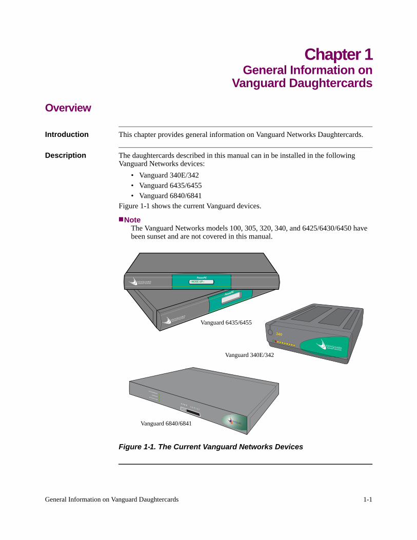
Description The daughtercards described in this manual can in be installed in the following Vanguard Networks devices:
• Vanguard 340E/342• Vanguard 6435/6455• Vanguard 6840/6841
Figure 1-1 shows the current Vanguard devices.
NoteThe Vanguard Networks models 100, 305, 320, 340, and 6425/6430/6450 have been sunset and are not covered in this manual.
--NODE UP--
Vanguard 6435/6455
Vanguard 340E/342
Vanguard 6840/6841
Figure 1-1. The Current Vanguard Networks Devices
1-2 General Information on Vanguard Daughtercards
Vanguard Daughtercards
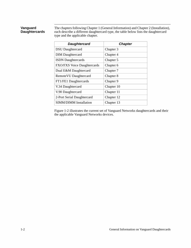
The chapters following Chapter 1 (General Information) and Chapter 2 (Installation), each describe a different daughtercard type, the table below lists the daughtercard type and the applicable chapter
Daughtercard ChapterDSU Daughtercard Chapter 3 DIM Daughtercard Chapter 4 ISDN Daughtercards Chapter 5 FXO/FXS Voice Daughtercards Chapter 6 Dual E&M Daughtercard Chapter 7 RemoteVU Daughtercard Chapter 8 FT1/FE1 Daughtercards Chapter 9 V.34 Daughtercard Chapter 10 V.90 Daughtercard Chapter 11 2-Port Serial Daughtercard Chapter 12 SIMM/DIMM Installation Chapter 13
.
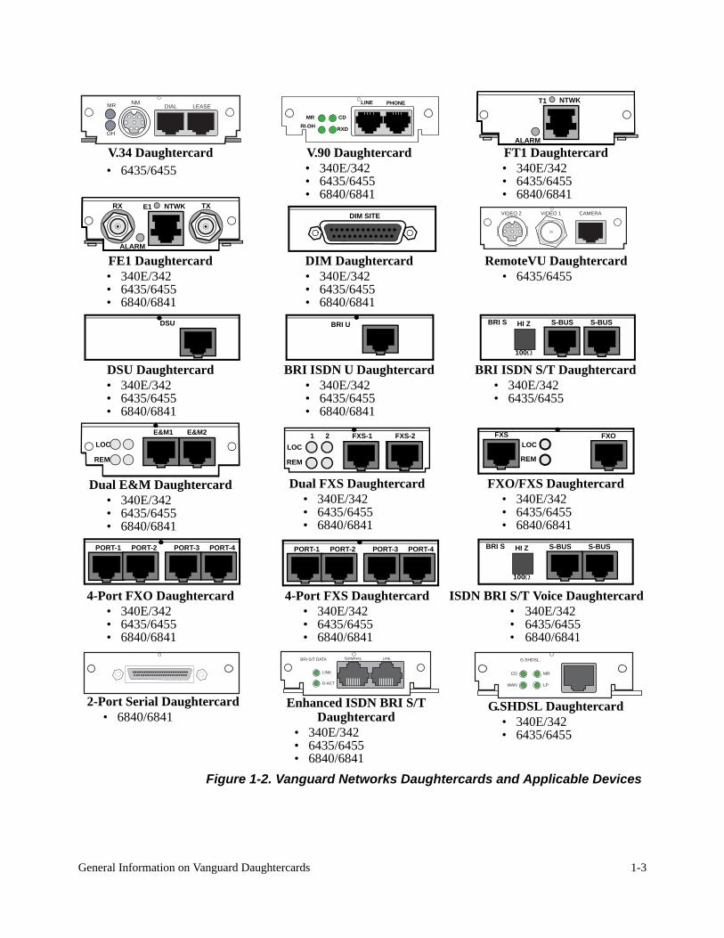
Figure 1-2 illustrates the current set of Vanguard Networks daughtercards and their the applicable Vanguard Networks devices.
RI OHCD
.MR
RXD
LINE PHONE
DIM SITE
DSU
BRI-S/T DATA
LINK
D-ACT
TERMINAL LINE
S-BUS
100Ω
HI Z S-BUSBRI S
FXS FXOLOC
REMLOC
REM
FXS-1 FXS-21 2
PORT-1 PORT-2 PORT-3 PORT-4PORT-1 PORT-2 PORT-3 PORT-4
T1 NTWK
ALARM
E1RX TXNTWK
ALARM
LOC
REM
E&M1 E&M2
G.SHDSL
MR
LP
CD
WAN
VIDEO 2 VIDEO 1 CAMERA
NMMR
OH
LEASEDIAL
V.34 Daughtercard• 6435/6455
V.90 Daughtercard• 340E/342• 6435/6455• 6840/6841
FT1 Daughtercard• 340E/342• 6435/6455• 6840/6841
FE1 Daughtercard• 340E/342• 6435/6455• 6840/6841
DIM Daughtercard• 340E/342• 6435/6455• 6840/6841
RemoteVU Daughtercard• 6435/6455
BRI U
DSU Daughtercard• 340E/342• 6435/6455• 6840/6841
BRI ISDN U Daughtercard• 340E/342• 6435/6455• 6840/6841
BRI ISDN S/T Daughtercard• 340E/342• 6435/6455
S-BUS
100Ω
HI Z S-BUSBRI S
Dual E&M Daughtercard• 340E/342• 6435/6455• 6840/6841
Dual FXS Daughtercard• 340E/342• 6435/6455• 6840/6841
FXO/FXS Daughtercard• 340E/342• 6435/6455• 6840/6841
4-Port FXO Daughtercard• 340E/342• 6435/6455• 6840/6841
4-Port FXS Daughtercard• 340E/342• 6435/6455• 6840/6841
ISDN BRI S/T Voice Daughtercard• 340E/342• 6435/6455• 6840/6841
2-Port Serial Daughtercard• 6840/6841
Enhanced ISDN BRI S/T Daughtercard
• 340E/342• 6435/6455• 6840/6841
G.SHDSL Daughtercard• 340E/342• 6435/6455
General Information on Vanguard Daughtercards 1-3
Figure 1-2. Vanguard Networks Daughtercards and Applicable Devices
1-4 General Information on Vanguard Daughtercards
Standard Packaging
Standard Packaging
Introduction This section describes the shipping contents of a typical Daughtercard Installation Kit.
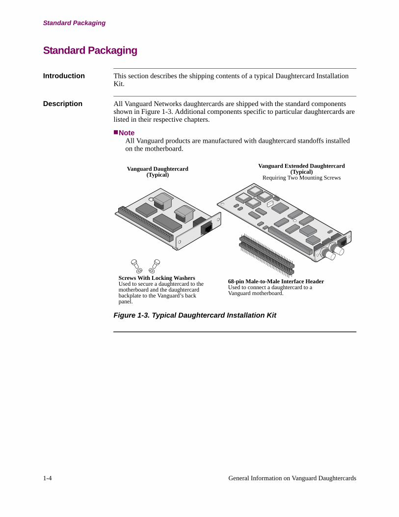
Description All Vanguard Networks daughtercards are shipped with the standard components shown in Figure 1-3. Additional components specific to particular daughtercards are listed in their respective chapters.
NoteAll Vanguard products are manufactured with daughtercard standoffs installed on the motherboard.
Screws With Locking WashersUsed to secure a daughtercard to the motherboard and the daughtercard backplate to the Vanguard’s back panel.
68-pin Male-to-Male Interface HeaderUsed to connect a daughtercard to a Vanguard motherboard.
Vanguard Daughtercard(Typical)
Vanguard Extended Daughtercard(Typical)
Requiring Two Mounting Screws
Figure 1-3. Typical Daughtercard Installation Kit
Daughtercard Installation 2-1
Chapter 2Daughtercard Installation
Overview
Introduction This chapter describes the how to install a Vanguard Networks Daughtercard into Vanguard Networks devices.
Description The current line of Vanguard Networks Daughtercards can be installed into three hardware platforms. They are:
• Vanguard 340E/342• Vanguard 6435/6455• Vanguard 6840/6841
CautionFor Australian applications, only qualified installation personnel should install daughtercards.
2-2 Daughtercard Installation
Vanguard 340E/342 Daughtercard Installation
Vanguard 340E/342 Daughtercard Installation
Introduction This following sections describe how to install a daughtercard into a Vanguard 340E/342.
Before You Begin To install daughtercards in the Vanguard 340, you must first remove the motherboard from the enclosure as described below.
Accessing the Motherboard in a Vanguard 340E/342
Introduction This section explains how access the motherboard in a Vanguard 340E/342 to install a daughtercard.
Before You Begin Power down and disconnect your Vanguard unit from its power source before removing the top cover and front panel, or handling any components.
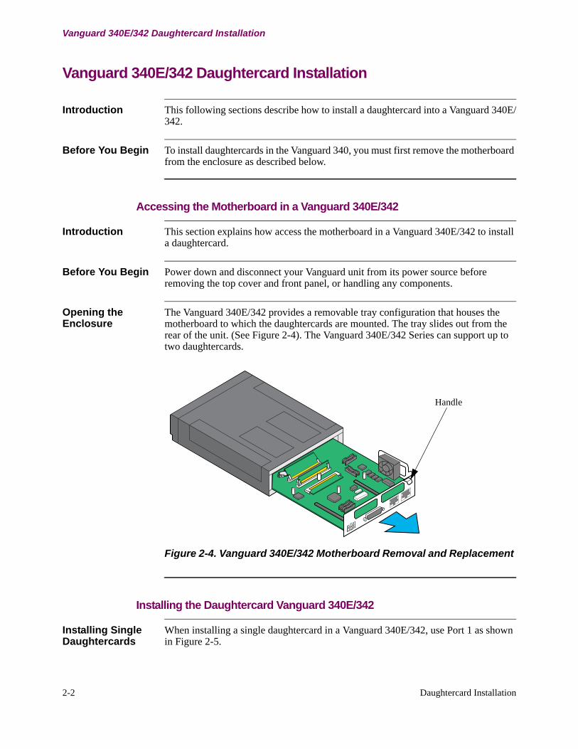
Opening the Enclosure
The Vanguard 340E/342 provides a removable tray configuration that houses the motherboard to which the daughtercards are mounted. The tray slides out from the rear of the unit. (See Figure 2-4). The Vanguard 340E/342 Series can support up to two daughtercards.
Handle
Figure 2-4. Vanguard 340E/342 Motherboard Removal and Replacement
Installing the Daughtercard Vanguard 340E/342
Installing Single Daughtercards
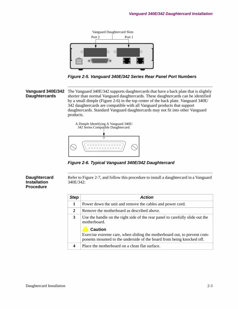
When installing a single daughtercard in a Vanguard 340E/342, use Port 1 as shown in Figure 2-5.
Vanguard Daughtercard SlotsPort 2 Port 1
RJ-45 CTP Port 4
Daughtercard Installation 2-3
Vanguard 340E/342 Daughtercard Installation
Figure 2-5. Vanguard 340E/342 Series Rear Panel Port Numbers
Vanguard 340E/342 Daughtercards
The Vanguard 340E/342 supports daughtercards that have a back plate that is slightly shorter than normal Vanguard daughtercards. These daughtercards can be identified by a small dimple (Figure 2-6) in the top center of the back plate. Vanguard 340E/342 daughtercards are compatible with all Vanguard products that support daughtercards. Standard Vanguard daughtercards may not fit into other Vanguard products.
A Dimple Identifying A Vanguard 340E/342 Series Compatible Daughtercard.
Figure 2-6. Typical Vanguard 340E/342 Daughtercard
Daughtercard Installation Procedure
Refer to Figure 2-7, and follow this procedure to install a daughtercard in a Vanguard 340E/342:
Step Action 1 Power down the unit and remove the cables and power cord.2 Remove the motherboard as described above. 3 Use the handle on the right side of the rear panel to carefully slide out the
motherboard.
CautionExercise extreme care, when sliding the motherboard out, to prevent com-ponents mounted to the underside of the board from being knocked off.
4 Place the motherboard on a clean flat surface.

2-4 Daughtercard Installation
Vanguard 340E/342 Daughtercard Installation
5 If you are... Then...Adding a daughtercard Connect the 68-pin interface header onto the
motherboard. Install this daughtercard in daughtercard slots for Port 1.
Replacing a daughter-card
a) Remove the daughtercard mounting screw that attaches the daughtercard to the board.
b) Unscrew the two rear panel coverplate screws. Unplug the existing daughtercard. If no daughtercard is installed, remove the metal blanking plate.
c) Align the standoff on the motherboard with the hole on the new daughtercard.
6 Push the daughtercard down into the connector being careful to align the pins. Do not apply excessive pressure when pushing the daughtercard into the connector or you may damage the card.
7 Fasten the screw that attaches the daughtercard to the motherboard, then fasten the two rear panel coverplate screws. Daughtercard replacement/addition is complete.
8 Reinstall the motherboard by reversing Steps 1 through 3.
Step Action (continued)
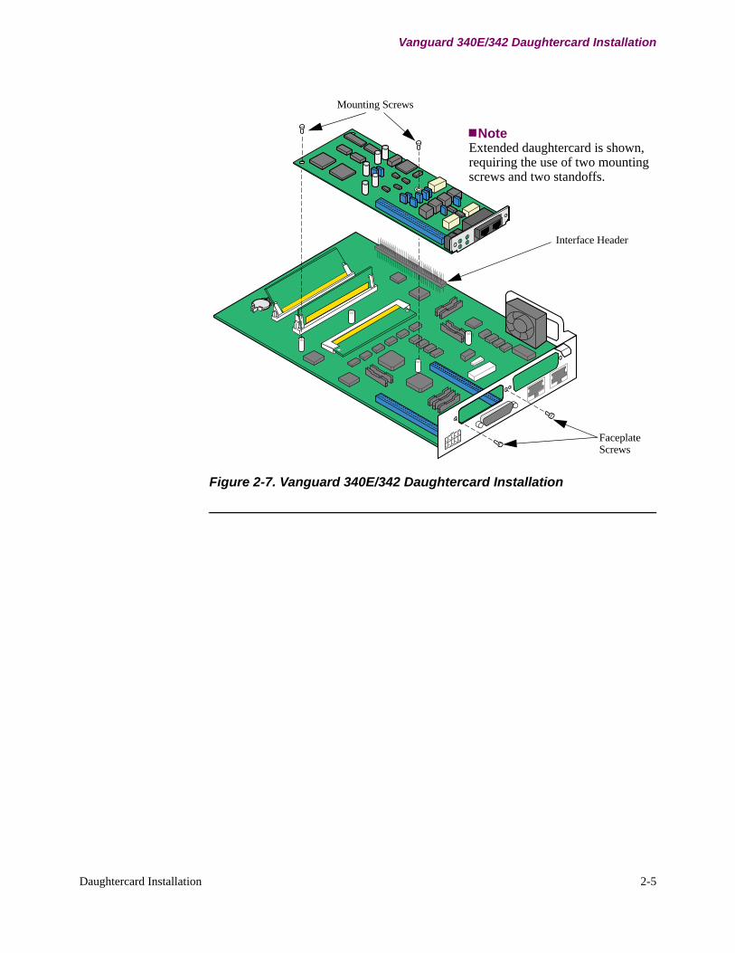
Mounting Screws
Interface Header
FaceplateScrews
NoteExtended daughtercard is shown, requiring the use of two mounting screws and two standoffs.
Daughtercard Installation 2-5
Vanguard 340E/342 Daughtercard Installation
Figure 2-7. Vanguard 340E/342 Daughtercard Installation
2-6 Daughtercard Installation
Vanguard 6435/6455 Series Daughtercard Installation
Vanguard 6435/6455 Series Daughtercard Installation
Introduction The following sections describe how to install a daughtercard into a Vanguard 6435/6455 Series.
Before You Begin To install daughtercards in a Vanguard 6435/6455, you must first remove the motherboard from the enclosure as described below.
Accessing the Motherboard in a Vanguard 6435/6455
Introduction This section explains how to access the motherboard in a Vanguard 6435/6455 to install a daughtercard.
Before You Begin Power down and disconnect your Vanguard unit from its power source before removing the top cover and front panel, or handling any components.
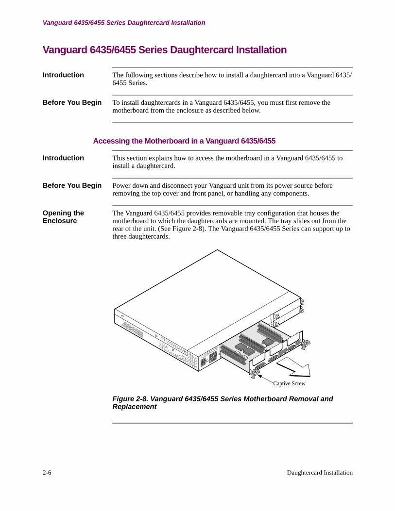
Opening the Enclosure
The Vanguard 6435/6455 provides removable tray configuration that houses the motherboard to which the daughtercards are mounted. The tray slides out from the rear of the unit. (See Figure 2-8). The Vanguard 6435/6455 Series can support up to three daughtercards.
Captive Screw
Figure 2-8. Vanguard 6435/6455 Series Motherboard Removal and Replacement
Daughtercard Installation 2-7
Vanguard 6435/6455 Series Daughtercard Installation
Installing the Daughtercard in a Vanguard 6435/6455
Installing Vanguard 6435/6455 Series Daughtercards
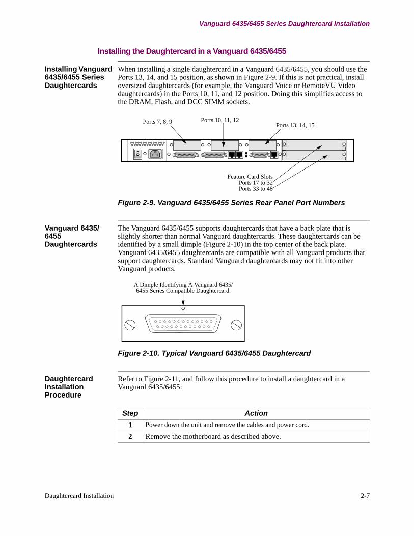
When installing a single daughtercard in a Vanguard 6435/6455, you should use the Ports 13, 14, and 15 position, as shown in Figure 2-9. If this is not practical, install oversized daughtercards (for example, the Vanguard Voice or RemoteVU Video daughtercards) in the Ports 10, 11, and 12 position. Doing this simplifies access to the DRAM, Flash, and DCC SIMM sockets.
Ports 7, 8, 9 Ports 13, 14, 15Ports 10, 11, 12
Feature Card SlotsPorts 17 to 32Ports 33 to 48
Figure 2-9. Vanguard 6435/6455 Series Rear Panel Port Numbers
Vanguard 6435/6455 Daughtercards
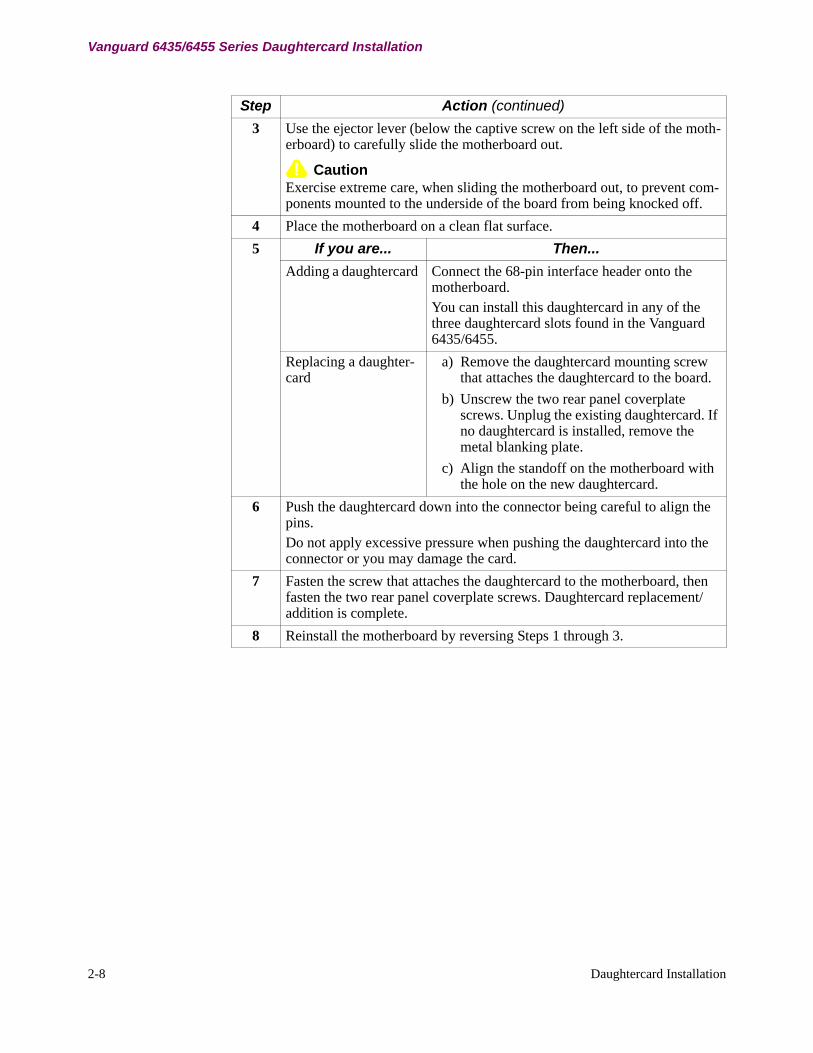
The Vanguard 6435/6455 supports daughtercards that have a back plate that is slightly shorter than normal Vanguard daughtercards. These daughtercards can be identified by a small dimple (Figure 2-10) in the top center of the back plate. Vanguard 6435/6455 daughtercards are compatible with all Vanguard products that support daughtercards. Standard Vanguard daughtercards may not fit into other Vanguard products.
A Dimple Identifying A Vanguard 6435/6455 Series Compatible Daughtercard.
Figure 2-10. Typical Vanguard 6435/6455 Daughtercard
Daughtercard Installation Procedure
Refer to Figure 2-11, and follow this procedure to install a daughtercard in a Vanguard 6435/6455:
Step Action 1 Power down the unit and remove the cables and power cord.
2 Remove the motherboard as described above.
2-8 Daughtercard Installation
Vanguard 6435/6455 Series Daughtercard Installation
3 Use the ejector lever (below the captive screw on the left side of the moth-erboard) to carefully slide the motherboard out.
CautionExercise extreme care, when sliding the motherboard out, to prevent com-ponents mounted to the underside of the board from being knocked off.
4 Place the motherboard on a clean flat surface.5 If you are... Then...
Adding a daughtercard Connect the 68-pin interface header onto the motherboard. You can install this daughtercard in any of the three daughtercard slots found in the Vanguard 6435/6455.
Replacing a daughter-card
a) Remove the daughtercard mounting screw that attaches the daughtercard to the board.
b) Unscrew the two rear panel coverplate screws. Unplug the existing daughtercard. If no daughtercard is installed, remove the metal blanking plate.
c) Align the standoff on the motherboard with the hole on the new daughtercard.
6 Push the daughtercard down into the connector being careful to align the pins.Do not apply excessive pressure when pushing the daughtercard into the connector or you may damage the card.
7 Fasten the screw that attaches the daughtercard to the motherboard, then fasten the two rear panel coverplate screws. Daughtercard replacement/addition is complete.
8 Reinstall the motherboard by reversing Steps 1 through 3.
Step Action (continued)
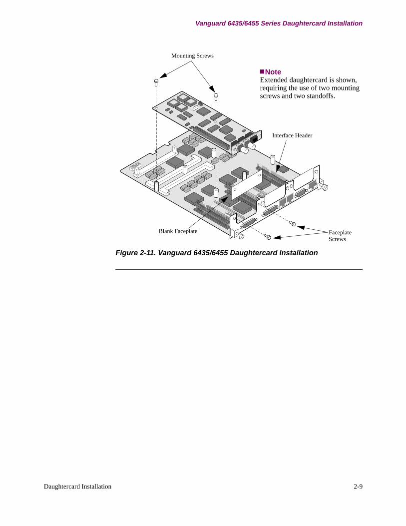
Mounting Screws
Interface Header
FaceplateScrews
Blank Faceplate
NoteExtended daughtercard is shown, requiring the use of two mounting screws and two standoffs.
Daughtercard Installation 2-9
Vanguard 6435/6455 Series Daughtercard Installation
Figure 2-11. Vanguard 6435/6455 Daughtercard Installation

2-10 Daughtercard Installation
Vanguard 6840/6841 Series Daughtercard Installation
Vanguard 6840/6841 Series Daughtercard Installation
Introduction The following sections describe how to install a daughtercard into a Vanguard 6840/6841 Series.
Before You Begin To install daughtercards in a Vanguard 6840/6841, you must first remove the motherboard from the enclosure as described below.
Accessing the Motherboard in a Vanguard 6840/6841
Introduction This section explains how to access the motherboard in a Vanguard 6840/6841 to install a daughtercard.
Before You Begin Power down and disconnect your Vanguard unit from its power source before removing the top cover and front panel, or handling any components.
NoteThe Compact Clash Memory Card will need to be removed prior to accessing the motherboard.
Accessing the Motherboard
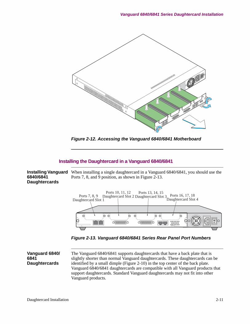
Refer to Figure 2-12, and follow this procedure to open the enclosure:
Step Action1 Power down the unit and remove the cables and power cord.2 Remove Compact Flash Memory Card3 Loosen the two captive screws on either side of the motherboard rear panel.4 Use the ejector lever to carefully slide out the motherboard.5 Place the motherboard on a clean flat surface.6 Install daughtercard as described in Chapter 2.7 To replace the cover, reverse the steps described above.
Daughtercard Installation 2-11
Vanguard 6840/6841 Series Daughtercard Installation
Figure 2-12. Accessing the Vanguard 6840/6841 Motherboard
Installing the Daughtercard in a Vanguard 6840/6841
Installing Vanguard 6840/6841 Daughtercards
When installing a single daughtercard in a Vanguard 6840/6841, you should use the Ports 7, 8, and 9 position, as shown in Figure 2-13.
Ports 7, 8, 9Daughtercard Slot 1
Ports 10, 11, 12Daughtercard Slot 2
Ports 13, 14, 15Daughtercard Slot 3 Ports 16, 17, 18
Daughtercard Slot 4
Figure 2-13. Vanguard 6840/6841 Series Rear Panel Port Numbers
Vanguard 6840/6841 Daughtercards
The Vanguard 6840/6841 supports daughtercards that have a back plate that is slightly shorter than normal Vanguard daughtercards. These daughtercards can be identified by a small dimple (Figure 2-10) in the top center of the back plate. Vanguard 6840/6841 daughtercards are compatible with all Vanguard products that support daughtercards. Standard Vanguard daughtercards may not fit into other Vanguard products.
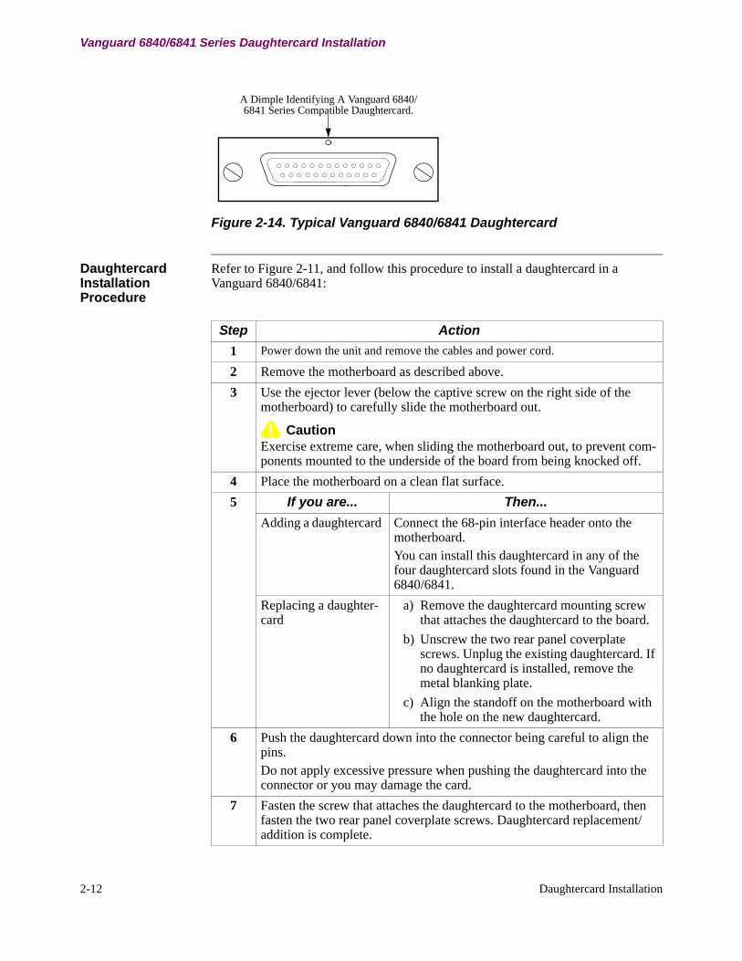
A Dimple Identifying A Vanguard 6840/6841 Series Compatible Daughtercard.
2-12 Daughtercard Installation
Vanguard 6840/6841 Series Daughtercard Installation
Figure 2-14. Typical Vanguard 6840/6841 Daughtercard
Daughtercard Installation Procedure
Refer to Figure 2-11, and follow this procedure to install a daughtercard in a Vanguard 6840/6841:
Step Action 1 Power down the unit and remove the cables and power cord.
2 Remove the motherboard as described above. 3 Use the ejector lever (below the captive screw on the right side of the
motherboard) to carefully slide the motherboard out.
CautionExercise extreme care, when sliding the motherboard out, to prevent com-ponents mounted to the underside of the board from being knocked off.
4 Place the motherboard on a clean flat surface.5 If you are... Then...
Adding a daughtercard Connect the 68-pin interface header onto the motherboard. You can install this daughtercard in any of the four daughtercard slots found in the Vanguard 6840/6841.
Replacing a daughter-card
a) Remove the daughtercard mounting screw that attaches the daughtercard to the board.
b) Unscrew the two rear panel coverplate screws. Unplug the existing daughtercard. If no daughtercard is installed, remove the metal blanking plate.
c) Align the standoff on the motherboard with the hole on the new daughtercard.
6 Push the daughtercard down into the connector being careful to align the pins.Do not apply excessive pressure when pushing the daughtercard into the connector or you may damage the card.
7 Fasten the screw that attaches the daughtercard to the motherboard, then fasten the two rear panel coverplate screws. Daughtercard replacement/addition is complete.
2-13
Vanguard 6840/6841 Series Daughtercard Installation
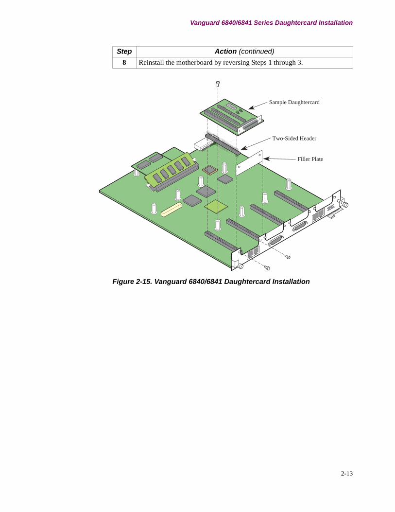
Figure 2-15. Vanguard 6840/6841 Daughtercard Installation
8 Reinstall the motherboard by reversing Steps 1 through 3.
Sample Daughtercard
Two-Sided Header
Filler Plate
Step Action (continued)

2-14
Vanguard 6840/6841 Series Daughtercard Installation
DSU Daughtercard 3-1
Chapter 3DSU Daughtercard
Overview
Introduction This chapter describes the Vanguard Networks’ DSU Daughtercard.
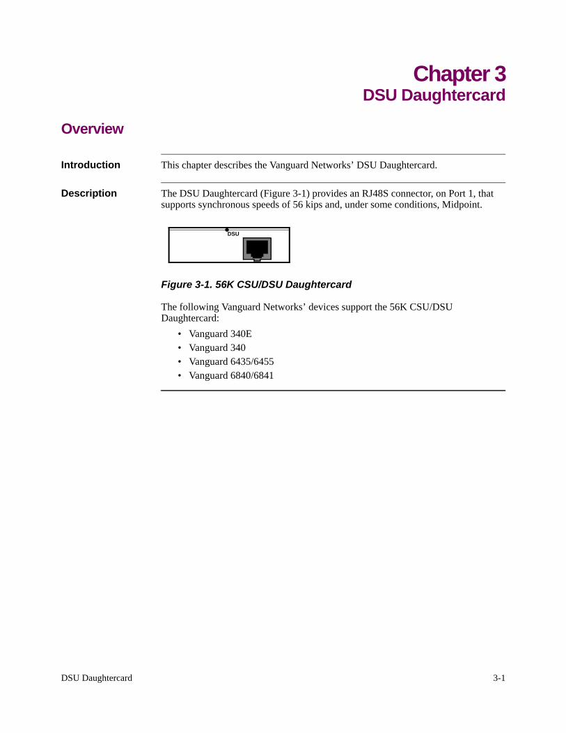
Description The DSU Daughtercard (Figure 3-1) provides an RJ48S connector, on Port 1, that supports synchronous speeds of 56 kips and, under some conditions, Midpoint.
DSU
Figure 3-1. 56K CSU/DSU Daughtercard
The following Vanguard Networks’ devices support the 56K CSU/DSU Daughtercard:
• Vanguard 340E• Vanguard 340• Vanguard 6435/6455• Vanguard 6840/6841

3-2 DSU Daughtercard
DIM Daughtercard Installation 4-1
Chapter 4DIM Daughtercard Installation
Overview
Introduction This chapter describes the DIM Daughtercard.
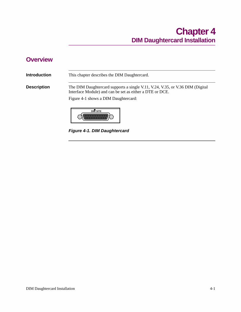
Description The DIM Daughtercard supports a single V.11, V.24, V.35, or V.36 DIM (Digital Interface Module) and can be set as either a DTE or DCE. Figure 4-1 shows a DIM Daughtercard:
DIM SITE
Figure 4-1. DIM Daughtercard
4-2 DIM Daughtercard Installation
Strapping the DIM Daughtercard
Strapping the DIM Daughtercard
Introduction This section describes how to set the straps on the DIM Daughtercard.
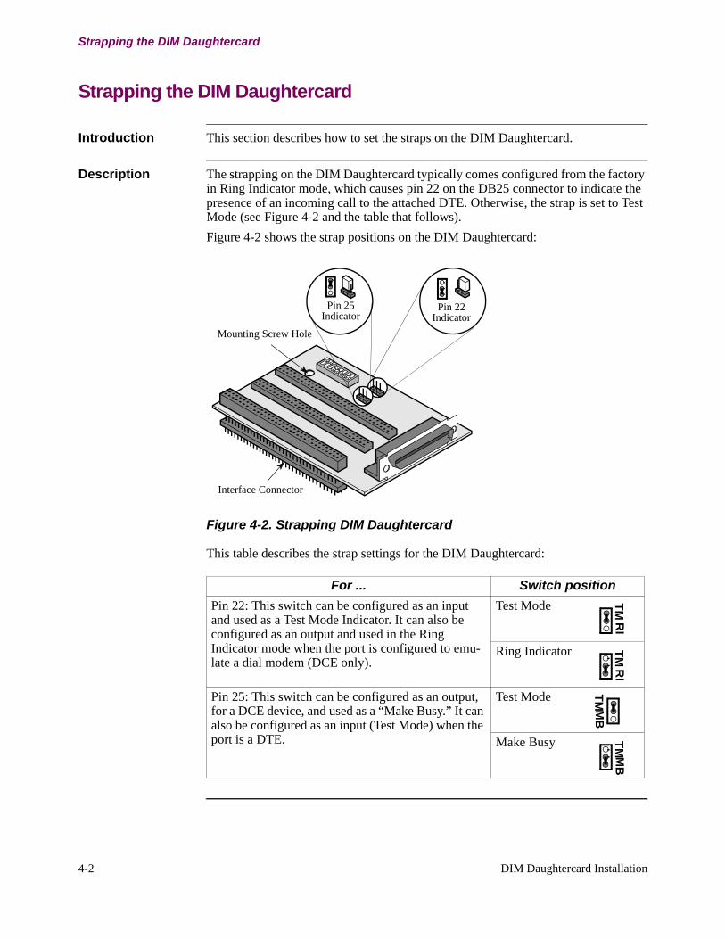
Description The strapping on the DIM Daughtercard typically comes configured from the factory in Ring Indicator mode, which causes pin 22 on the DB25 connector to indicate the presence of an incoming call to the attached DTE. Otherwise, the strap is set to Test Mode (see Figure 4-2 and the table that follows).Figure 4-2 shows the strap positions on the DIM Daughtercard:
Interface Connector
Mounting Screw Hole
Pin 25Indicator
Pin 22 Indicator
Figure 4-2. Strapping DIM Daughtercard
This table describes the strap settings for the DIM Daughtercard:
For ... Switch position Pin 22: This switch can be configured as an input and used as a Test Mode Indicator. It can also be configured as an output and used in the Ring Indicator mode when the port is configured to emu-late a dial modem (DCE only).
Test Mode TMR
I
Ring Indicator TMR
I
Pin 25: This switch can be configured as an output, for a DCE device, and used as a “Make Busy.” It can also be configured as an input (Test Mode) when the port is a DTE.
Test Mode TMM
B
Make Busy TMM
B

DIM Daughtercard Installation 4-3
Setting the Switches on the DIM Daughtercard
Setting the Switches on the DIM Daughtercard
Introduction This table identifies the DIP switch settings for the DIM Daughtercard:
For Set Switch To ... Switch PositionsV.11 DIM 1-5
6-8OffOn On
87654321
V.24 DIM 1-56-8
OnOff On
87654321
V.35 DIM 1-56-8
OffOn On
87654321
V.36 DIM 1-56-8
OffOn On
87654321
4-4 DIM Daughtercard Installation
Installing a DIM on a DIM Daughtercard
Installing a DIM on a DIM Daughtercard
Introduction This chapter describes how to install DIMs in DIM Daughtercards.
Description Five different DIM devices can be installed into DIM Daughtercards including: DSU DIM, V.11 DIM, V.24 DIM, V.35 DIM, and V.36 DIM.
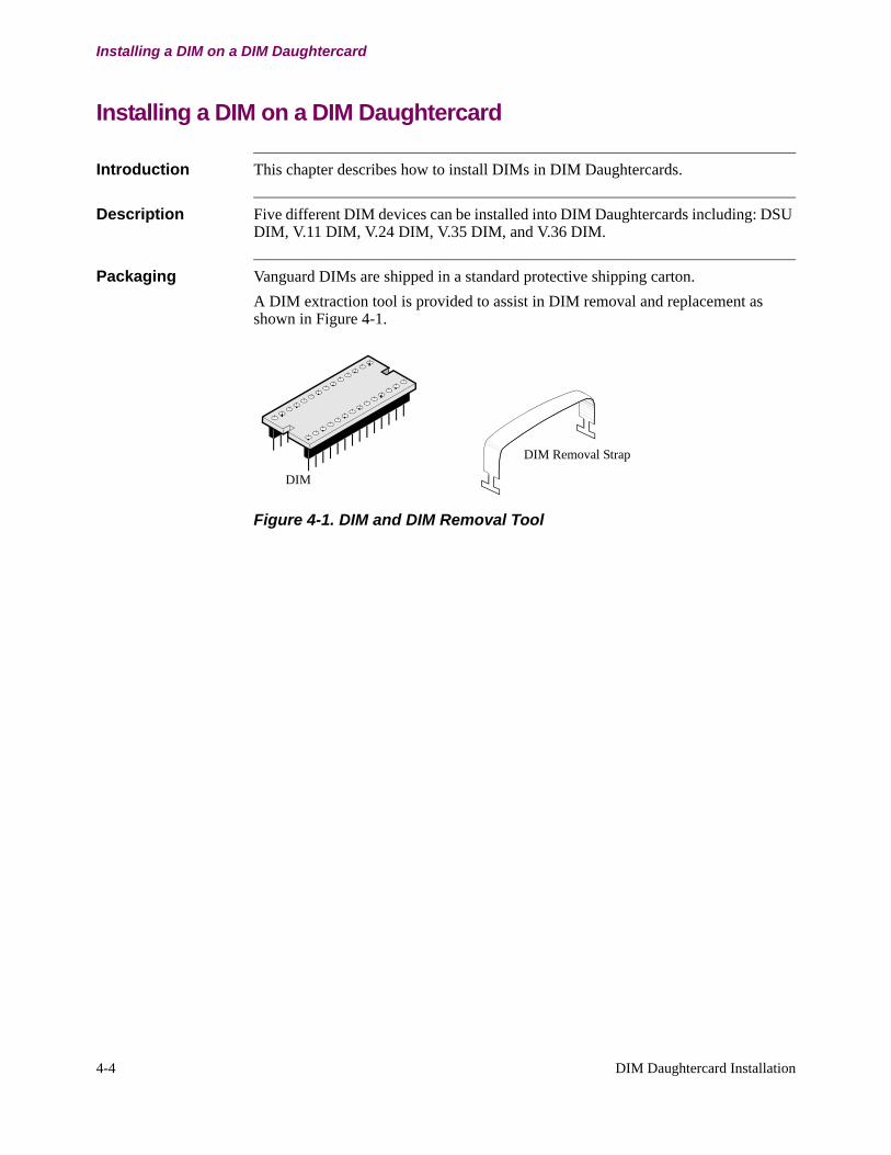
Packaging Vanguard DIMs are shipped in a standard protective shipping carton. A DIM extraction tool is provided to assist in DIM removal and replacement as shown in Figure 4-1.
DIM Removal Strap
DIM
Figure 4-1. DIM and DIM Removal Tool
DIM Daughtercard Installation 4-5
DIM Installation
DIM Installation
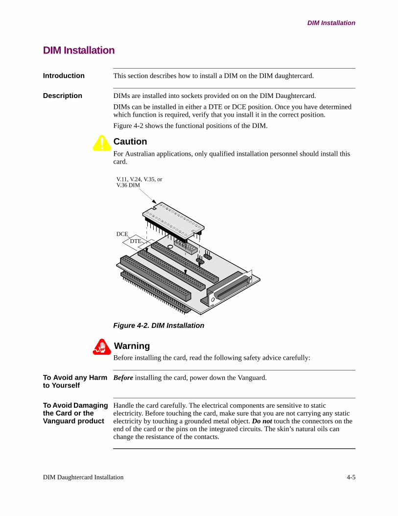
Introduction This section describes how to install a DIM on the DIM daughtercard.
Description DIMs are installed into sockets provided on on the DIM Daughtercard.DIMs can be installed in either a DTE or DCE position. Once you have determined which function is required, verify that you install it in the correct position.Figure 4-2 shows the functional positions of the DIM.
CautionFor Australian applications, only qualified installation personnel should install this card.
DCEDTE
V.11, V.24, V.35, or V.36 DIM
Figure 4-2. DIM Installation
WarningBefore installing the card, read the following safety advice carefully:
To Avoid any Harm to Yourself
Before installing the card, power down the Vanguard.
To Avoid Damaging the Card or the Vanguard product
Handle the card carefully. The electrical components are sensitive to static electricity. Before touching the card, make sure that you are not carrying any static electricity by touching a grounded metal object. Do not touch the connectors on the end of the card or the pins on the integrated circuits. The skin’s natural oils can change the resistance of the contacts.

4-6 DIM Daughtercard Installation
DIM Installation
ISDN Daughtercards 5-1
Chapter 5ISDN Daughtercards
Overview
Introduction This chapter describes the Vanguard Networks’ ISDN Daughtercards. They are:
• ISDN BRI-U• ISDN BRI-S/T• Enhanced ISDN BRI S/T Data• ISDN BRI S/T Voice
ISDN BRI-U Daughtercard
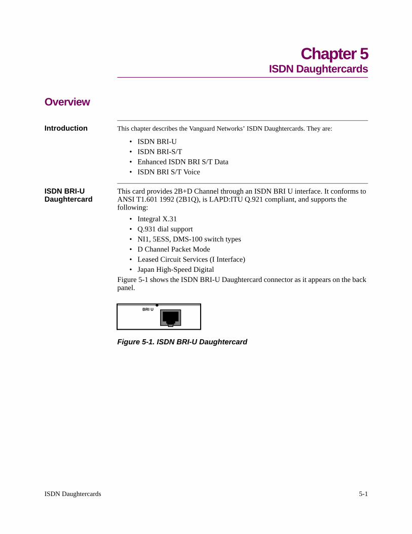
This card provides 2B+D Channel through an ISDN BRI U interface. It conforms to ANSI T1.601 1992 (2B1Q), is LAPD:ITU Q.921 compliant, and supports the following:
• Integral X.31• Q.931 dial support• NI1, 5ESS, DMS-100 switch types• D Channel Packet Mode• Leased Circuit Services (I Interface)• Japan High-Speed Digital
Figure 5-1 shows the ISDN BRI-U Daughtercard connector as it appears on the back panel.
BRI U
Figure 5-1. ISDN BRI-U Daughtercard
5-2 ISDN Daughtercards
ISDN BRI S/T Daughtercard
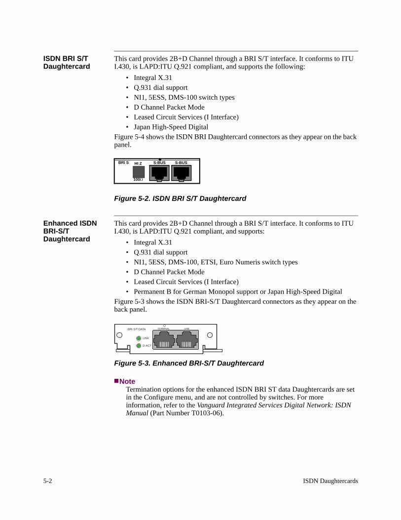
This card provides 2B+D Channel through a BRI S/T interface. It conforms to ITU I.430, is LAPD:ITU Q.921 compliant, and supports the following:
• Integral X.31• Q.931 dial support• NI1, 5ESS, DMS-100 switch types• D Channel Packet Mode• Leased Circuit Services (I Interface)• Japan High-Speed Digital
Figure 5-4 shows the ISDN BRI Daughtercard connectors as they appear on the back panel.
S-BUS
100Ω
HI Z S-BUSBRI S
Figure 5-2. ISDN BRI S/T Daughtercard
Enhanced ISDN BRI-S/T Daughtercard
This card provides 2B+D Channel through a BRI S/T interface. It conforms to ITU I.430, is LAPD:ITU Q.921 compliant, and supports:
• Integral X.31• Q.931 dial support• NI1, 5ESS, DMS-100, ETSI, Euro Numeris switch types• D Channel Packet Mode• Leased Circuit Services (I Interface)• Permanent B for German Monopol support or Japan High-Speed Digital
Figure 5-3 shows the ISDN BRI-S/T Daughtercard connectors as they appear on the back panel.
BRI-S/T DATA
LINK
D-ACT
TERMINAL LINE
Figure 5-3. Enhanced BRI-S/T Daughtercard
NoteTermination options for the enhanced ISDN BRI ST data Daughtercards are set in the Configure menu, and are not controlled by switches. For more information, refer to the Vanguard Integrated Services Digital Network: ISDN Manual (Part Number T0103-06).
ISDN Daughtercards 5-3
ISDN BRI Voice Daughtercard
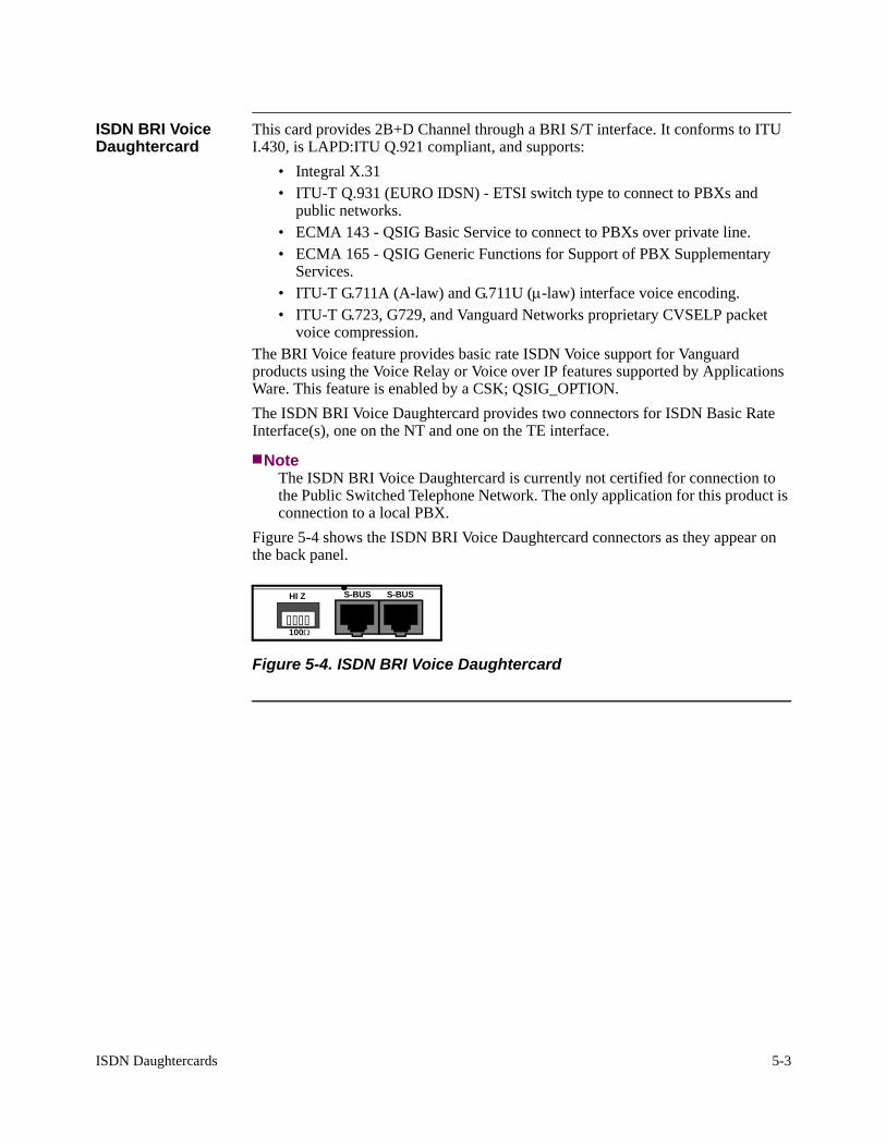
This card provides 2B+D Channel through a BRI S/T interface. It conforms to ITU I.430, is LAPD:ITU Q.921 compliant, and supports:
• Integral X.31• ITU-T Q.931 (EURO IDSN) - ETSI switch type to connect to PBXs and
public networks.• ECMA 143 - QSIG Basic Service to connect to PBXs over private line.• ECMA 165 - QSIG Generic Functions for Support of PBX Supplementary
Services.• ITU-T G.711A (A-law) and G.711U (µ-law) interface voice encoding.• ITU-T G.723, G729, and Vanguard Networks proprietary CVSELP packet
voice compression.The BRI Voice feature provides basic rate ISDN Voice support for Vanguard products using the Voice Relay or Voice over IP features supported by Applications Ware. This feature is enabled by a CSK; QSIG_OPTION.The ISDN BRI Voice Daughtercard provides two connectors for ISDN Basic Rate Interface(s), one on the NT and one on the TE interface.
NoteThe ISDN BRI Voice Daughtercard is currently not certified for connection to the Public Switched Telephone Network. The only application for this product is connection to a local PBX.
Figure 5-4 shows the ISDN BRI Voice Daughtercard connectors as they appear on the back panel.
S-BUS
100Ω
HI Z S-BUS
Figure 5-4. ISDN BRI Voice Daughtercard
5-4 ISDN Daughtercards
ISDN Cables
ISDN Cables
Introduction This section describes the cables used with the ISDN Daughtercards.
Description Each ISDN daughtercard ships with an ISDN connection cable. One end of the cable attaches directly to the daughtercard, and the other end connects to the service provider outlet. The connector pinouts are described below.The S/T network cabling is intended for use within a building and not for wiring exposed to lightening or power cross. The interface to external (U network) wiring should be done with an isolating NT1 interface.
Cable Connector Pin Numbers
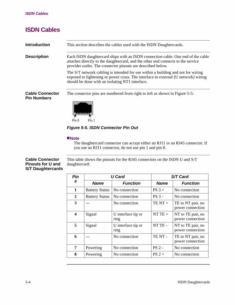
The connector pins are numbered from right to left as shown in Figure 5-5:
Pin 8 Pin 1
Figure 5-5. ISDN Connector Pin Out
NoteThe daughtercard connector can accept either an RJ11 or an RJ45 connector. If you use an RJ11 connector, do not use pin 1 and pin 8.
Cable Connector Pinouts for U and S/T Daughtercards
This table shows the pinouts for the RJ45 connectors on the ISDN U and S/T daughtercard:
Pin#
U Card S/T Card Name Function Name Function
1 Battery Status No connection PS 3 + No connection2 Battery Status No connection PS 3 - No connection3 --- No connection TE NT + TE to NT pair, no
power connection4 Signal U interface tip or
ringNT TE + NT to TE pair, no
power connection5 Signal U interface tip or
ringNT TE - NT to TE pair, no
power connection6 --- No connection TE NT - TE to NT pair, no
power connection7 Powering No connection PS 2 - No connection8 Powering No connection PS 2 + No connection
ISDN Daughtercards 5-5
ISDN Cables
Cable Connector Pinouts for Voice Daughtercard
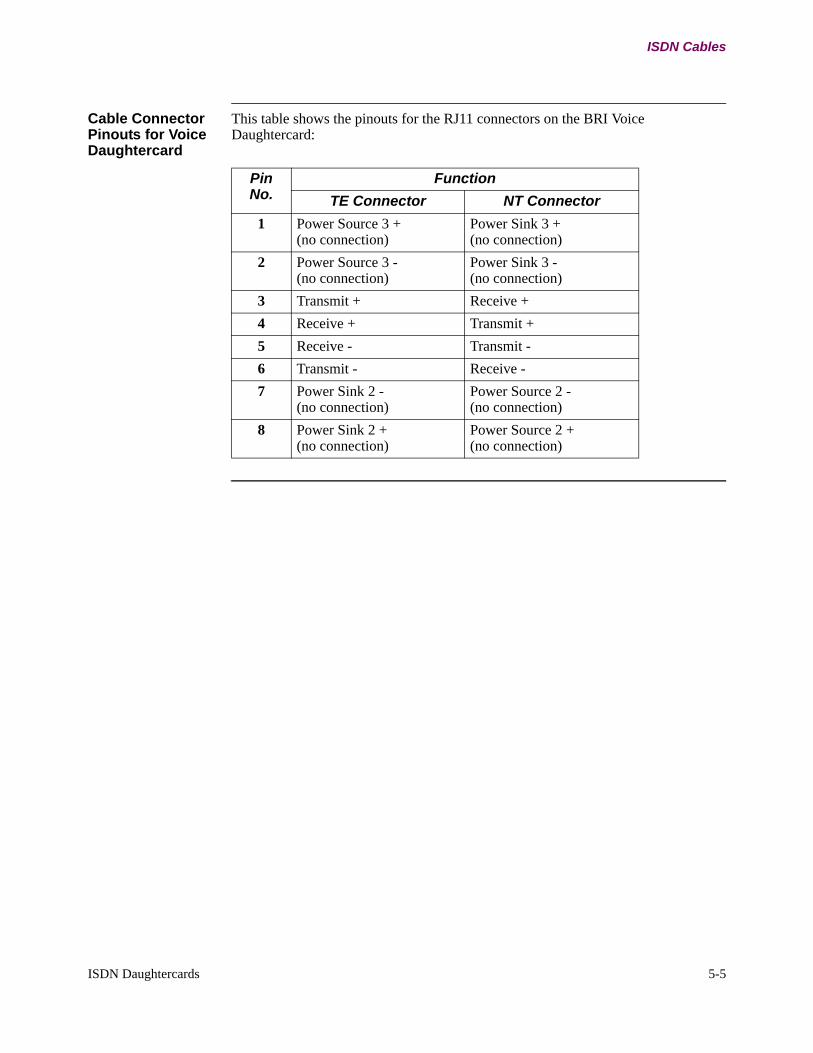
This table shows the pinouts for the RJ11 connectors on the BRI Voice Daughtercard:
PinNo.
Function TE Connector NT Connector
1 Power Source 3 + (no connection)
Power Sink 3 + (no connection)
2 Power Source 3 - (no connection)
Power Sink 3 - (no connection)
3 Transmit + Receive +4 Receive + Transmit +5 Receive - Transmit -6 Transmit - Receive -7 Power Sink 2 -
(no connection)Power Source 2 - (no connection)
8 Power Sink 2 + (no connection)
Power Source 2 + (no connection)
5-6 ISDN Daughtercards
Setting S/T and Voice ISDN Termination Resistance
Setting S/T and Voice ISDN Termination Resistance
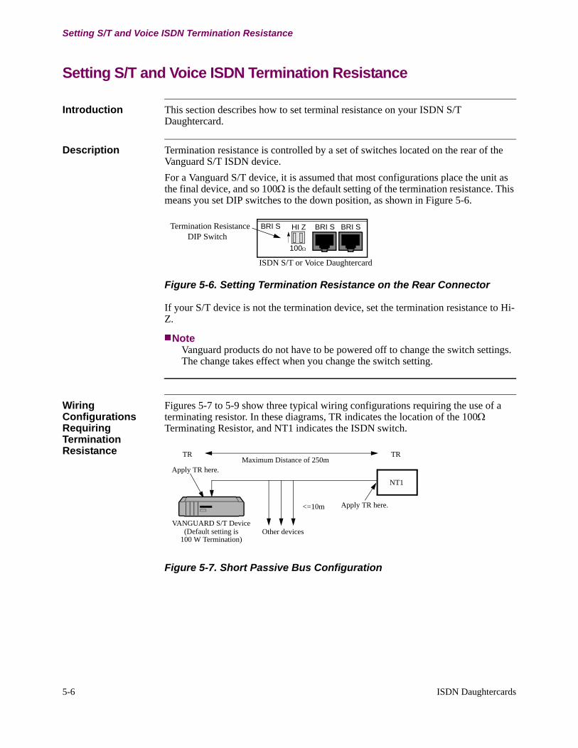
Introduction This section describes how to set terminal resistance on your ISDN S/T Daughtercard.
Description Termination resistance is controlled by a set of switches located on the rear of the Vanguard S/T ISDN device.For a Vanguard S/T device, it is assumed that most configurations place the unit as the final device, and so 100Ω is the default setting of the termination resistance. This means you set DIP switches to the down position, as shown in Figure 5-6.
BRI SHI Z BRI SBRI S
ISDN S/T or Voice Daughtercard
Termination ResistanceDIP Switch
100Ω
Figure 5-6. Setting Termination Resistance on the Rear Connector
If your S/T device is not the termination device, set the termination resistance to Hi-Z.
NoteVanguard products do not have to be powered off to change the switch settings. The change takes effect when you change the switch setting.
Wiring Configurations Requiring Termination Resistance
Figures 5-7 to 5-9 show three typical wiring configurations requiring the use of a terminating resistor. In these diagrams, TR indicates the location of the 100Ω Terminating Resistor, and NT1 indicates the ISDN switch.
VANGUARD S/T Device
NT1
<=10m
TRTRMaximum Distance of 250m
Other devices
Apply TR here.
Apply TR here.
(Default setting is100 W Termination)
Figure 5-7. Short Passive Bus Configuration
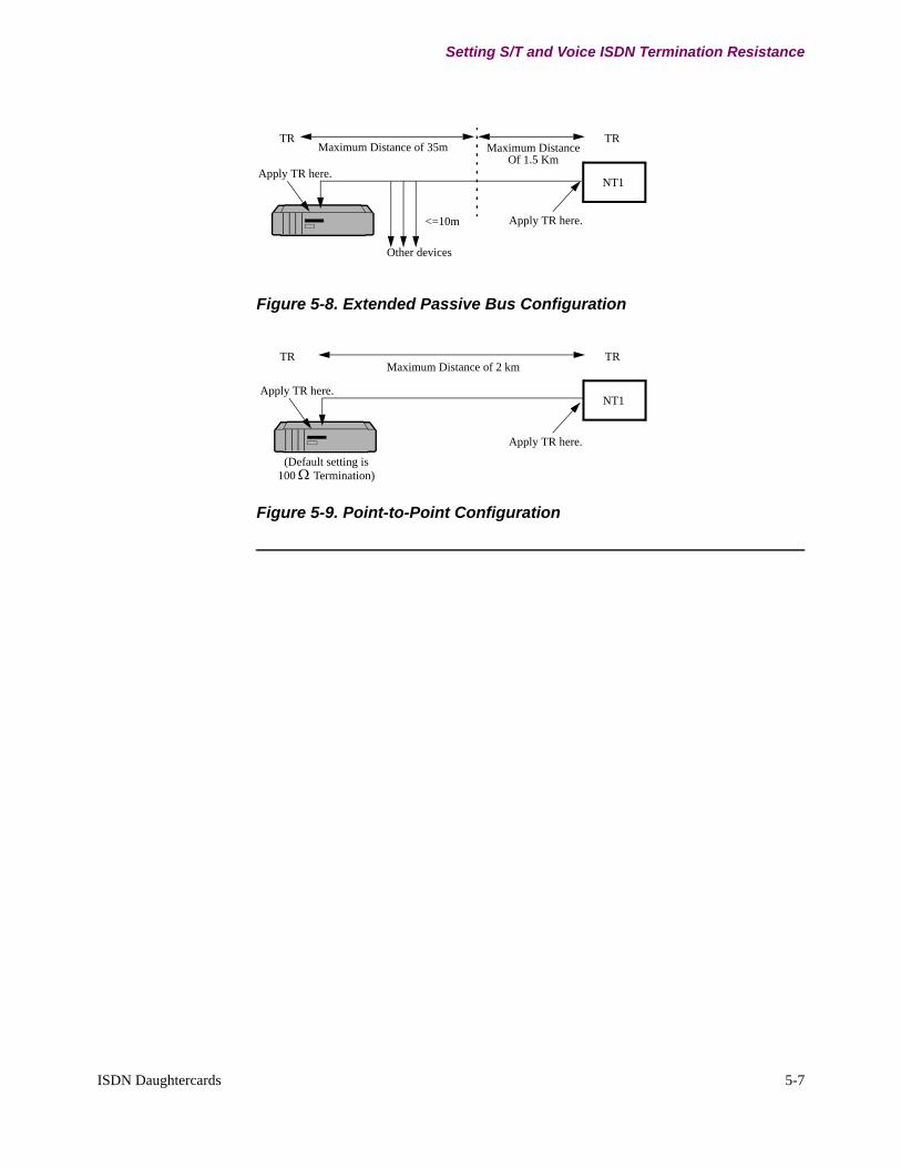
NT1
<=10m
TRTRMaximum Distance of 35m
Apply TR here.
Other devices
Maximum DistanceOf 1.5 Km
Apply TR here.
ISDN Daughtercards 5-7
Setting S/T and Voice ISDN Termination Resistance
Figure 5-8. Extended Passive Bus Configuration
NT1
TRTRMaximum Distance of 2 km
Apply TR here.
(Default setting is100 Ω Termination)
Apply TR here.
Figure 5-9. Point-to-Point Configuration

5-8 ISDN Daughtercards
European Approval Labels
European Approval Labels
Introduction This section describes the European Approval Labels used with the ISDN Daughtercard.
Description When you install an ISDN S/T Daughtercard into a Vanguard product for first time use in countries such as Germany, France, and the Netherlands, it may be necessary for you to obtain certain approval labels. These labels, listed below, can be obtained from your vendor and must be applied to the underside of the Vanguard product.
• Germany - BZT ISDN S/T label A120 187F• France - DRG Approval label 96089B• Netherlands - NL 96211204 label
FXO/FXS Voice Daughtercards 6-1
Chapter 6FXO/FXS Voice Daughtercards
Overview
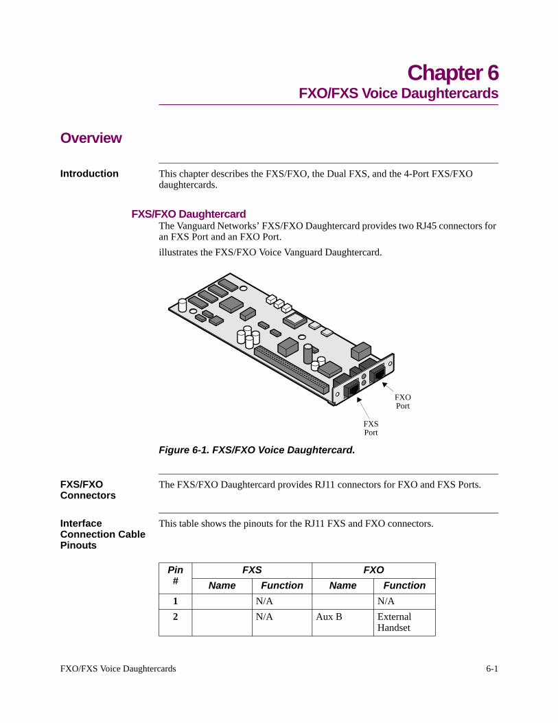
Introduction This chapter describes the FXS/FXO, the Dual FXS, and the 4-Port FXS/FXO daughtercards.
FXS/FXO DaughtercardThe Vanguard Networks’ FXS/FXO Daughtercard provides two RJ45 connectors for an FXS Port and an FXO Port. illustrates the FXS/FXO Voice Vanguard Daughtercard.
FXS
FXO
Port
Port
Figure 6-1. FXS/FXO Voice Daughtercard.
FXS/FXO Connectors
The FXS/FXO Daughtercard provides RJ11 connectors for FXO and FXS Ports.
Interface Connection Cable Pinouts
This table shows the pinouts for the RJ11 FXS and FXO connectors.
Pin#
FXS FXO Name Function Name Function
1 N/A N/A2 N/A Aux B External
Handset
6-2 FXO/FXS Voice Daughtercards
NoteConnect the FXS Interface to an analog telephone handset and/or fax machine only.
NoteConnect the FXO Interface to an analog PBX line only. The Vanguard One Port FXS/FXO daughtercard is not certified for use in a PSTN.
WarningOnly for connection with telephone equipment, do not connect this daughtercard directly to a network.
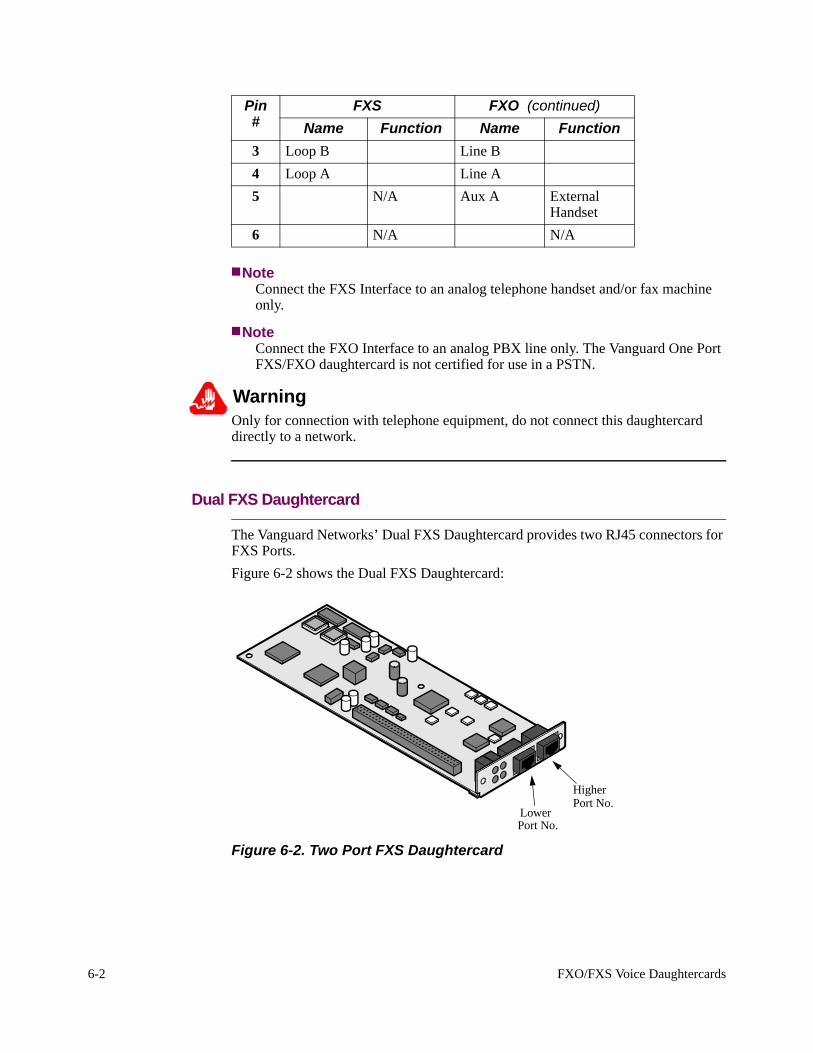
Dual FXS Daughtercard
The Vanguard Networks’ Dual FXS Daughtercard provides two RJ45 connectors for FXS Ports. Figure 6-2 shows the Dual FXS Daughtercard:
Lower
Higher
Port No.
Port No.
Figure 6-2. Two Port FXS Daughtercard
3 Loop B Line B4 Loop A Line A5 N/A Aux A External
Handset6 N/A N/A
Pin#
FXS FXO (continued)Name Function Name Function
FXO/FXS Voice Daughtercards 6-3
Port Assignments Unlike the One Port FXS/FXO Daughtercard, the Dual FXS Daughtercard can use both ports simultaneously. This table lists the port assignments for the card when it is installed in various Vanguard products:
Platform Port AssignmentsVanguard 340 1 and 6
2 and 7Vanguard 64xx 7 and 8
10 and 1113 and 14
Vanguard 68xx
When looking at the rear panel, the port on the left has the lower number and the port of the right has the higher.
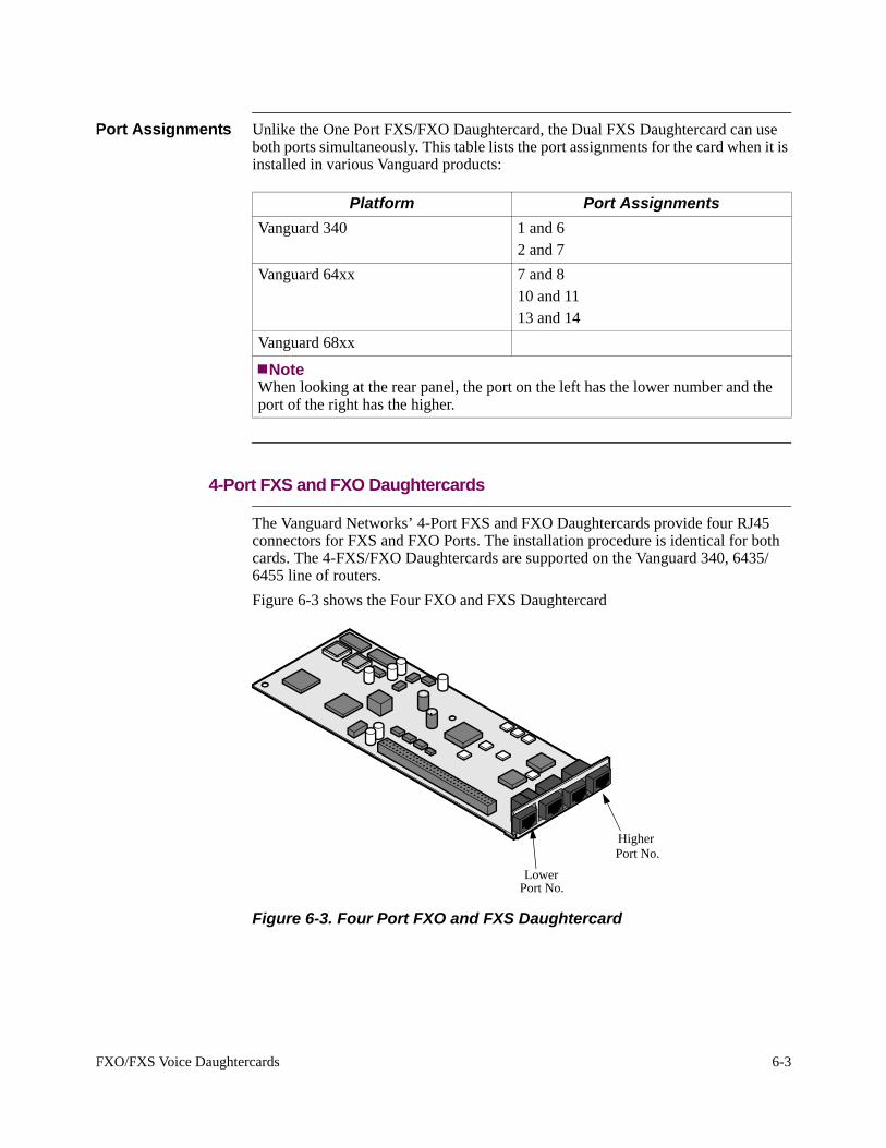
4-Port FXS and FXO Daughtercards
The Vanguard Networks’ 4-Port FXS and FXO Daughtercards provide four RJ45 connectors for FXS and FXO Ports. The installation procedure is identical for both cards. The 4-FXS/FXO Daughtercards are supported on the Vanguard 340, 6435/6455 line of routers. Figure 6-3 shows the Four FXO and FXS Daughtercard
HigherPort No.
Port No.Lower
Figure 6-3. Four Port FXO and FXS Daughtercard
Note
6-4 FXO/FXS Voice Daughtercards
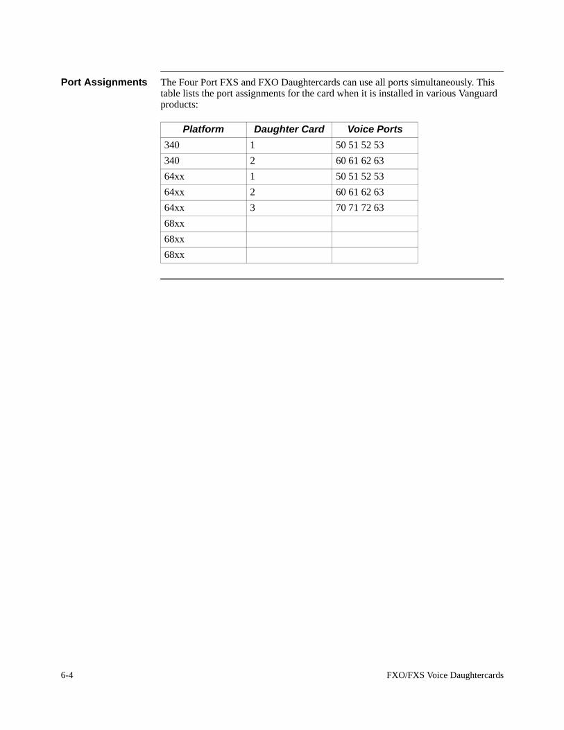
Port Assignments The Four Port FXS and FXO Daughtercards can use all ports simultaneously. This table lists the port assignments for the card when it is installed in various Vanguard products:
Platform Daughter Card Voice Ports340 1 50 51 52 53340 2 60 61 62 6364xx 1 50 51 52 5364xx 2 60 61 62 6364xx 3 70 71 72 6368xx68xx68xx
Dual E&M Daughtercard 7-1
Chapter 7Dual E&M Daughtercard
Overview
Introduction This chapter describes the Vanguard Network’s Dual E&M daughtercard.
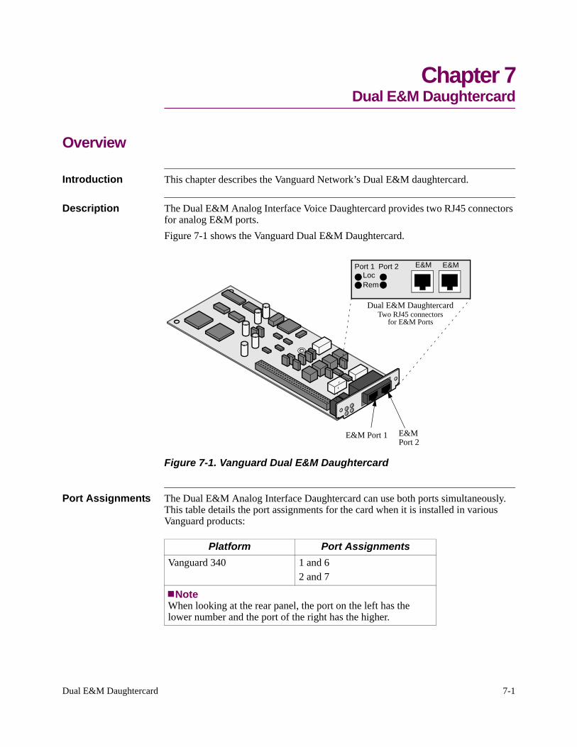
Description The Dual E&M Analog Interface Voice Daughtercard provides two RJ45 connectors for analog E&M ports.Figure 7-1 shows the Vanguard Dual E&M Daughtercard.
E&M Port 1 E&MPort 2
Dual E&M DaughtercardTwo RJ45 connectors
for E&M Ports
E&MPort 1 Port 2
RemLoc
E&M
Figure 7-1. Vanguard Dual E&M Daughtercard
Port Assignments The Dual E&M Analog Interface Daughtercard can use both ports simultaneously. This table details the port assignments for the card when it is installed in various Vanguard products:
Platform Port AssignmentsVanguard 340 1 and 6
2 and 7
NoteWhen looking at the rear panel, the port on the left has the lower number and the port of the right has the higher.
7-2 Dual E&M Daughtercard
Dual E&M Jumper Settings
Dual E&M Jumper Settings
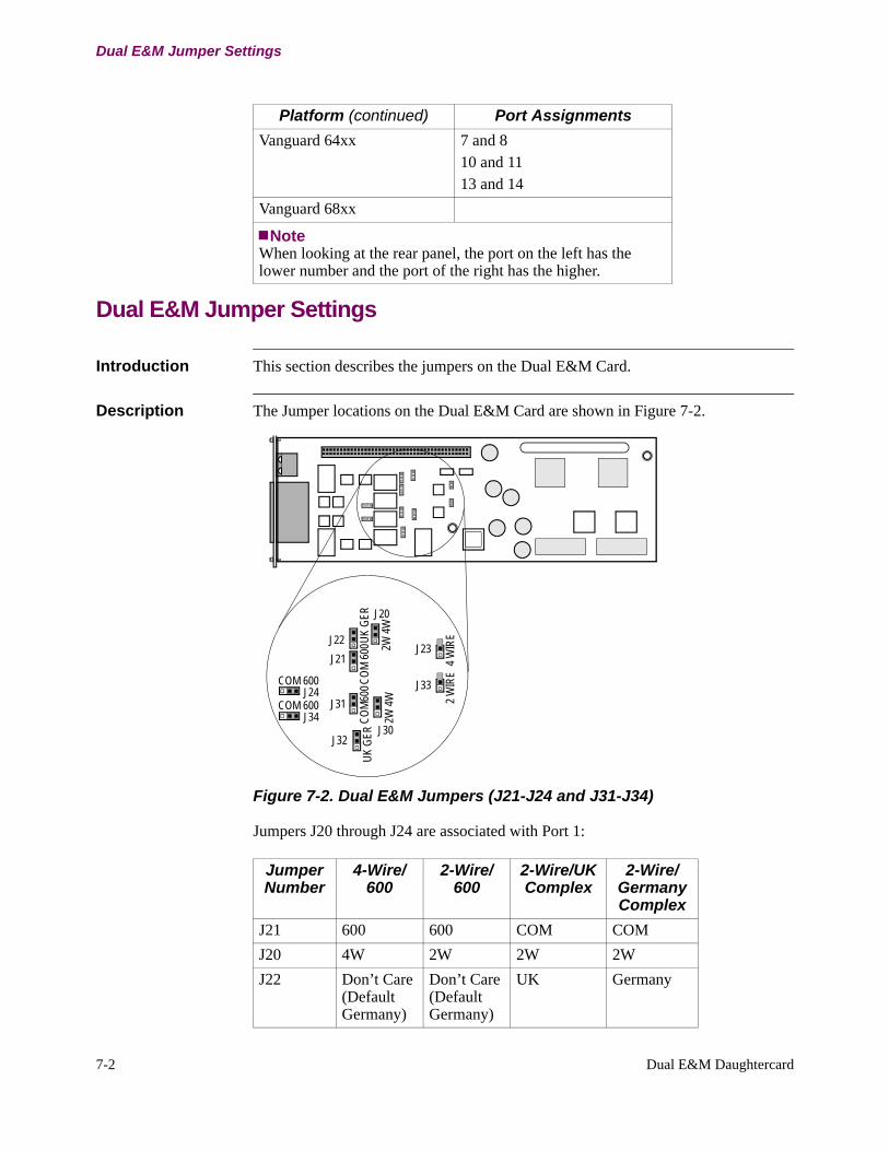
Introduction This section describes the jumpers on the Dual E&M Card.
Description The Jumper locations on the Dual E&M Card are shown in Figure 7-2.
J24
J34
J32
J31
J21J22
J20
J30
J33
J23
COM 600
COM 600
UK G
ERCO
M600
COM
600U
K GE
R
2W 4W
2W 4W 2 W
IRE
4 WIR
E
Figure 7-2. Dual E&M Jumpers (J21-J24 and J31-J34)
Jumpers J20 through J24 are associated with Port 1:
Vanguard 64xx 7 and 810 and 1113 and 14
Vanguard 68xx
Platform (continued) Port Assignments
NoteWhen looking at the rear panel, the port on the left has the lower number and the port of the right has the higher.
Jumper Number
4-Wire/600
2-Wire/600
2-Wire/UK Complex
2-Wire/Germany Complex
J21 600 600 COM COMJ20 4W 2W 2W 2WJ22 Don’t Care
(Default Germany)
Don’t Care (Default Germany)
UK Germany
Dual E&M Daughtercard 7-3
Cable Pinout
Jumpers J30 through J34 are associated with Port 2:
Jumper Number
4-Wire/600
2-Wire/600
2-Wire/UK Complex
2-Wire/Germany Complex
J31 600 600 COM COMJ30 4W 2W 2W 2WJ32 Don’t Care
(Default Germany)
Don’t Care (Default Germany)
UK Germany
J33 4W (removed)
2W (installed)
2W (installed)
2W (installed)
J34 600 600 COM COM
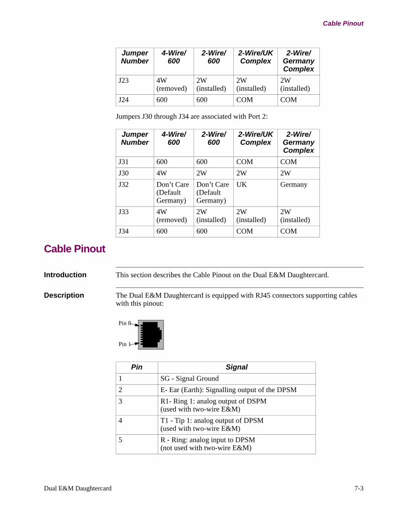
Cable Pinout
Introduction This section describes the Cable Pinout on the Dual E&M Daughtercard.
Description The Dual E&M Daughtercard is equipped with RJ45 connectors supporting cables with this pinout
Pin 8
Pin 1
:
J23 4W (removed)
2W (installed)
2W (installed)
2W (installed)
J24 600 600 COM COM
Jumper Number
4-Wire/600
2-Wire/600
2-Wire/UK Complex
2-Wire/Germany Complex
Pin Signal 1 SG - Signal Ground2 E- Ear (Earth): Signalling output of the DPSM3 R1- Ring 1: analog output of DSPM
(used with two-wire E&M)4 T1 - Tip 1: analog output of DPSM
(used with two-wire E&M)5 R - Ring: analog input to DPSM
(not used with two-wire E&M)

7-4 Dual E&M Daughtercard
Cable Pinout
E&M Type The E & M Type—Type I, II, IV, or V—is software configurable, and it does not require a hardware strap to configure type.
6 T - Tip: analog input to DPSM (not used with two-wire E&M)
7 M - Mouth (Magnet): signaling input to the DPSM8 SB - Signal Battery
Pin Signal (continued)
RemoteVU Daughtercard 8-1
Chapter 8RemoteVU Daughtercard
Overview
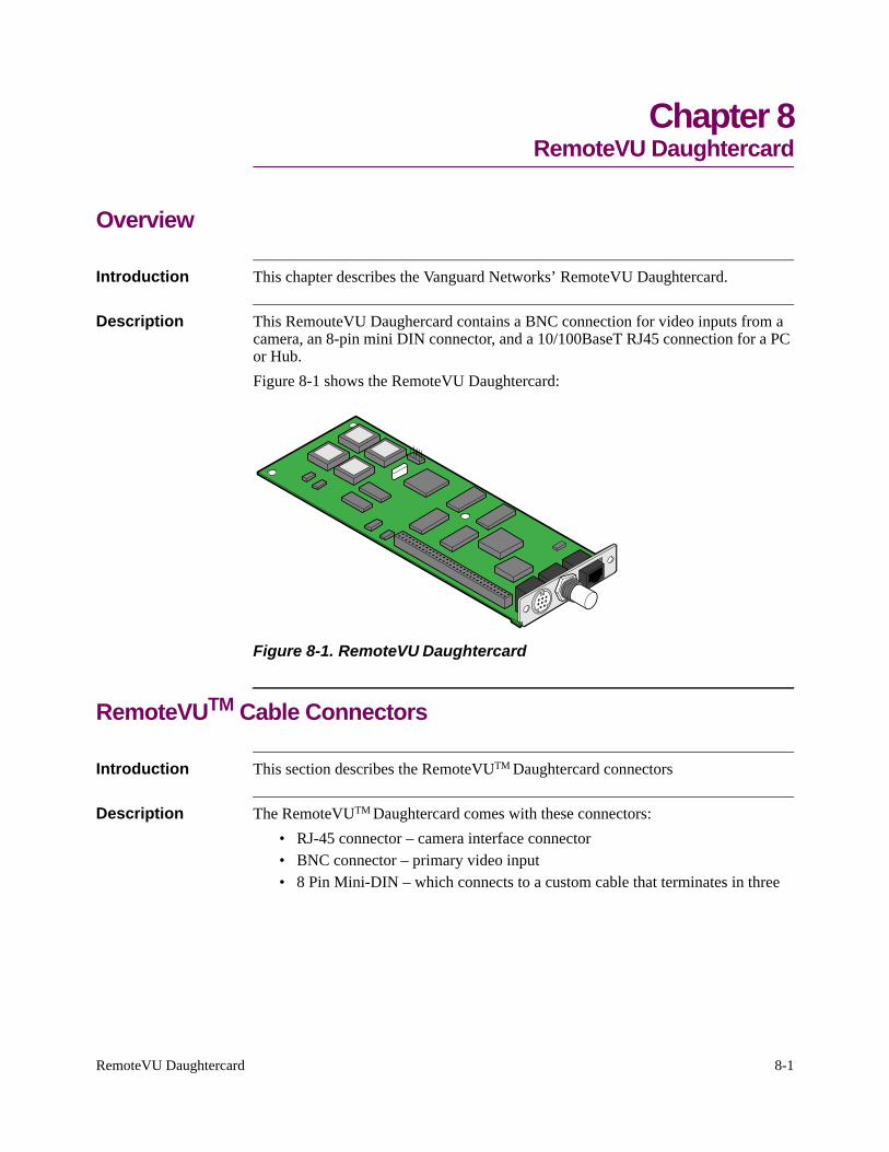
Introduction This chapter describes the Vanguard Networks’ RemoteVU Daughtercard.
Description This RemouteVU Daughercard contains a BNC connection for video inputs from a camera, an 8-pin mini DIN connector, and a 10/100BaseT RJ45 connection for a PC or Hub.Figure 8-1 shows the RemoteVU Daughtercard:
Figure 8-1. RemoteVU Daughtercard
RemoteVUTM Cable Connectors
Introduction This section describes the RemoteVUTM Daughtercard connectors
Description The RemoteVUTM Daughtercard comes with these connectors:• RJ-45 connector – camera interface connector• BNC connector – primary video input • 8 Pin Mini-DIN – which connects to a custom cable that terminates in three
8-2 RemoteVU Daughtercard
RemoteVUTM Cable Connectors
BNC connectors
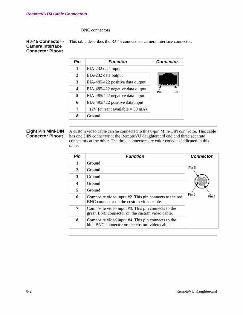
RJ-45 Connector - Camera Interface Connector Pinout
This table describes the RJ-45 connector - camera interface connector:
Pin Function Connector1 EIA-232 data input
Pin 8 Pin 1
2 EIA-232 data output 3 EIA-485/422 positive data output 4 EIA-485/422 negative data output 5 EIA-485/422 negative data input 6 EIA-485/422 positive data input 7 +12V (current available = 50 mA)8 Ground
Eight Pin Mini-DIN Connector Pinout
A custom video cable can be connected to this 8-pin Mini-DIN connector. This cable has one DIN connector at the RemoteVU daughtercard end and three separate connectors at the other. The three connectors are color coded as indicated in this table:
Pin Function Connector1 Ground
Pin 1Pin 5
Pin 82 Ground 3 Ground 4 Ground 5 Ground 6 Composite video input #2. This pin connects to the red
BNC connector on the custom video cable. 7 Composite video input #3. This pin connects to the
green BNC connector on the custom video cable.8 Composite video input #4. This pin connects to the
blue BNC connector on the custom video cable.
FT1/FE1 Daughtercard 9-1
Chapter 9FT1/FE1 Daughtercard
Overview
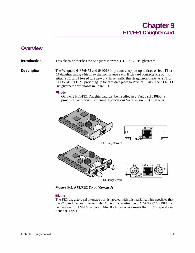
Introduction This chapter describes the Vanguard Networks’ FT1/FE1 Daughtercard.
Description The Vanguard 6435/6455 and 6840/6841 products support up to three or four T1 or E1 daughtercards, with three channel groups each. Each card connects one port to either a T1 or E1 leased line network. Essentially, this daughtercard acts as a T1 or E1 DSU/CSU DIM, providing up to three data pipes to Physical Ports. The FT1/ET1 Daughtercards are shown inFigure 9-1.
NoteOnly one FT1/FE1 Daughtercard can be installed in a Vanguard 340E/342 provided that product is running Applications Ware version 5.3 or greater.
FT1 Daughtercard
FE1 Daughtercard
T1 NTWK
ALARM
E1RX TXNTWK
ALARM
Figure 9-1. FT1/FE1 Daughtercards
NoteThe FE1 daughtercard interface port is labeled with this marking. This specifies that the E1 interface complies with the Australian requirements ACA TS 016 - 1997 for connection to E1 SELV services. Also the E1 interface meets the IEC950 specifica-tions for TNV1.
9-2 FT1/FE1 Daughtercard
FE1 Daughtercard Settings
FT1/FE1 Supported Functions
The FT1/FE1 Daughtercard (D/C) has these functions:• E1 with line rates of 2.048Mbps and data rates of 64Kbps per channel (max
31 channels).• T1 with line rates of 1.544Mbps and data rates of 56Kbps or 64Kbps per
channel (max. 24 channels).
NoteThe FT1/FE1 Daughtercard only operates in these Vanguard devices:• Vanguard 6840/6841• Vanguard 6435/6455 • Vanguard 340E• Vanguard 342
Indicators This daughtercard has one indicator LED, on the rear panel. This LED is under software con-trol and indicates:
• OFF: indicating Normal Operation, that is data passes from the network to the application.
• ON: indicating that an alarm condition exists. For specific information, you should refer to the T1/E1 Interface Statistics from the CTP Main menu.
FE1 Daughtercard Settings
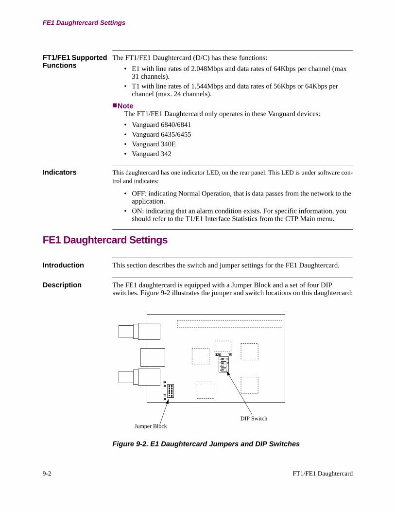
Introduction This section describes the switch and jumper settings for the FE1 Daughtercard.
Description The FE1 daughtercard is equipped with a Jumper Block and a set of four DIP switches. Figure 9-2 illustrates the jumper and switch locations on this daughtercard:
RX
TX
ON
12
34
120 75
Jumper BlockDIP Switch
Figure 9-2. E1 Daughtercard Jumpers and DIP Switches
FT1/FE1 Daughtercard 9-3
FE1 Daughtercard Settings
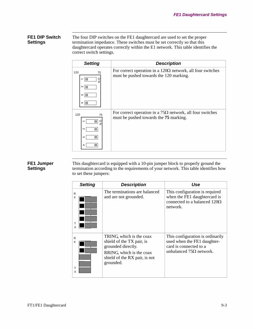
FE1 DIP Switch Settings
The four DIP switches on the FE1 daughtercard are used to set the proper termination impedance. These switches must be set correctly so that this daughtercard operates correctly within the E1 network. This table identifies the correct switch settings
Setting Description
12
34
O N
75120 For correct operation in a 120Ω network, all four switches must be pushed towards the 120 marking.
12
34
O N
75120 For correct operation in a 75Ω network, all four switches must be pushed towards the 75 marking.
.
FE1 Jumper Settings
This daughtercard is equipped with a 10-pin jumper block to properly ground the termination according to the requirements of your network. This table identifies how to set these jumpers:
Setting Description Use
R X
T X
The terminations are balanced and are not grounded.
This configuration is required when the FE1 daughtercard is connected to a balanced 120Ω network.
R X
T X
TRING, which is the coax shield of the TX pair, is grounded directly.RRING, which is the coax shield of the RX pair, is not grounded.
This configuration is ordinarily used when the FE1 daughter-card is connected to a unbalanced 75Ω network.
R X
T X
9-4 FT1/FE1 Daughtercard
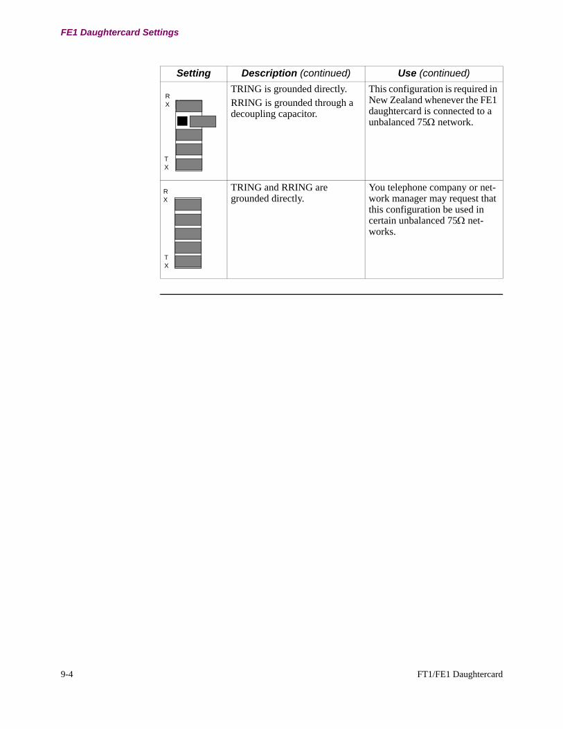
FE1 Daughtercard Settings
TRING is grounded directly.RRING is grounded through a decoupling capacitor.
This configuration is required in New Zealand whenever the FE1 daughtercard is connected to a unbalanced 75Ω network.
R X
T X
TRING and RRING are grounded directly.
You telephone company or net-work manager may request that this configuration be used in certain unbalanced 75Ω net-works.
Setting Description (continued) Use (continued)
V.34 Daughtercard 10-1
Chapter 10V.34 Daughtercard
Overview
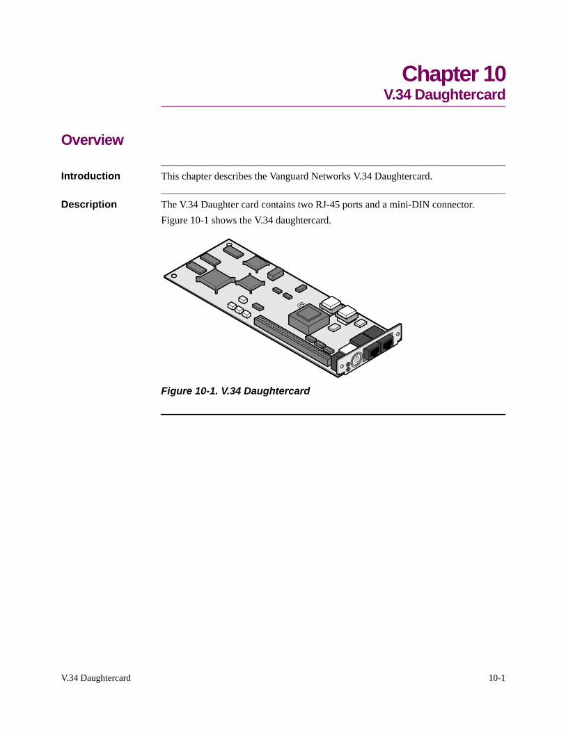
Introduction This chapter describes the Vanguard Networks V.34 Daughtercard.
Description The V.34 Daughter card contains two RJ-45 ports and a mini-DIN connector.Figure 10-1 shows the V.34 daughtercard.
Figure 10-1. V.34 Daughtercard

10-2 V.34 Daughtercard

V.90 Daughtercard 11-1
Chapter 11V.90 Daughtercard
Overview
Introduction This chapter describes the Vanguard Networks V.90 Daughtercard.
Description The V.90 modem daughtercard provides Async PPP dial back-up for a customers’ applications or can be used for Async dial connections such as remote CTP access. The V.90 uses a dual RJ-11 for connection to central offices, PBXs or telephone systems. V.90 is designed for the Vanguard 6840 and 6841.Figure 11-1 shows the rear panel connections for the V.90 daughtercard.
RI OHCD
.MR
RXD
LINE PHONE
Figure 11-1. V.34 Daughtercard

11-2 V.90 Daughtercard
2-Port Serial Daughtercard 12-1
Chapter 122-Port Serial Daughtercard
Overview
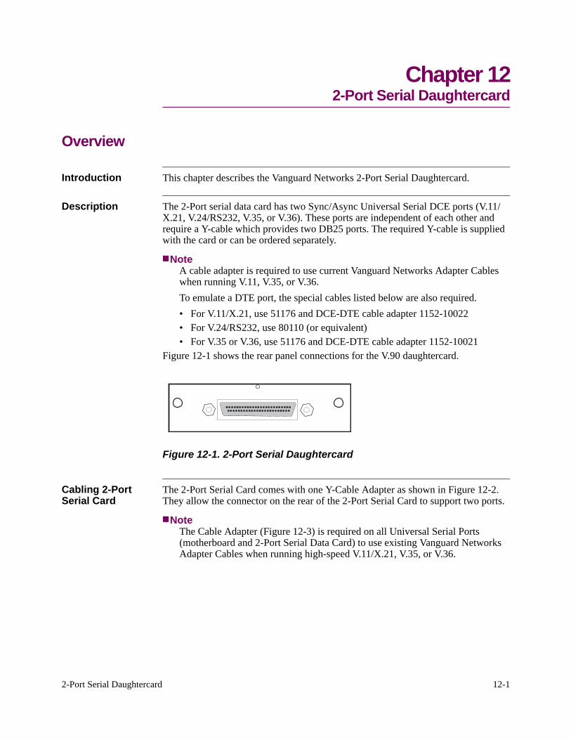
Introduction This chapter describes the Vanguard Networks 2-Port Serial Daughtercard.
Description The 2-Port serial data card has two Sync/Async Universal Serial DCE ports (V.11/X.21, V.24/RS232, V.35, or V.36). These ports are independent of each other and require a Y-cable which provides two DB25 ports. The required Y-cable is supplied with the card or can be ordered separately.
NoteA cable adapter is required to use current Vanguard Networks Adapter Cables when running V.11, V.35, or V.36.To emulate a DTE port, the special cables listed below are also required.• For V.11/X.21, use 51176 and DCE-DTE cable adapter 1152-10022• For V.24/RS232, use 80110 (or equivalent)• For V.35 or V.36, use 51176 and DCE-DTE cable adapter 1152-10021
Figure 12-1 shows the rear panel connections for the V.90 daughtercard.
Figure 12-1. 2-Port Serial Daughtercard
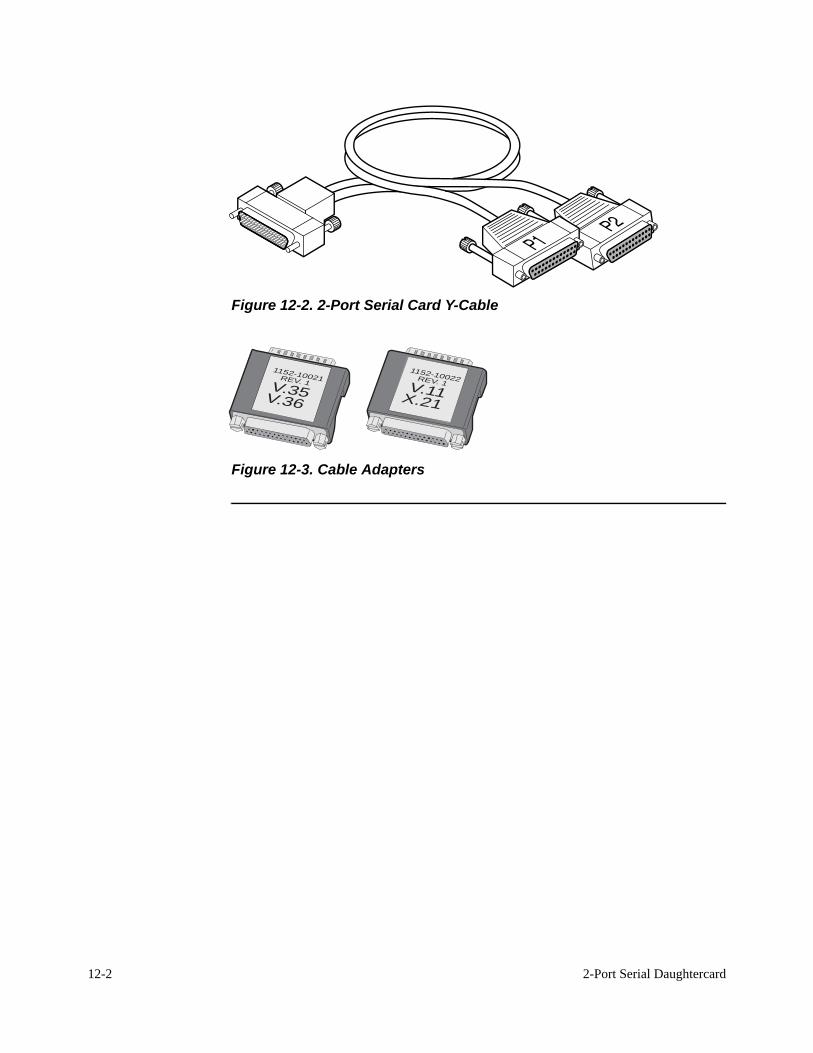
Cabling 2-Port Serial Card
The 2-Port Serial Card comes with one Y-Cable Adapter as shown in Figure 12-2. They allow the connector on the rear of the 2-Port Serial Card to support two ports.
NoteThe Cable Adapter (Figure 12-3) is required on all Universal Serial Ports (motherboard and 2-Port Serial Data Card) to use existing Vanguard Networks Adapter Cables when running high-speed V.11/X.21, V.35, or V.36.
12-2 2-Port Serial Daughtercard
Figure 12-2. 2-Port Serial Card Y-Cable
1152-10021REV. 1V.35V.36
1152-10022REV. 1V.11X.21
Figure 12-3. Cable Adapters

SIMM/DIMM Installation 13-1
Chapter 13SIMM/DIMM Installation
Overview
Introduction This chapter describes how to install memory modules such as SIMMs (Single In-line Memory Module) and DIMMs (Dual In-line Memory Module) into various Vanguard products.
Why Install a Memory Modules?
There are several reasons for installing SIMMs and or DIMMs into Vanguard products:
• There are fewer than 100 Packet Buffers available in the node. Check the number of available Packet Buffers by examining the second page of the node statistics.
• Packet Buffers are used to receive and transmit frames on all ports. If there are not enough buffers available, frames could be discarded when bursts of data are received on the LAN port. This results in retransmissions and reduced net-work performance.
• You plan to have more than two hundred simultaneous X.25 calls in place within the node (either over an X.25 link or over an Annex G station on a Frame Relay link). The node requires 2 or 3 Data Buffers for each of the X.25 connections.
• The node generates alarms indicating that there is not enough memory avail-able to initialize some of the ports.
• To add Data Compression or Data Encryption functionality to your Vanguard device.
13-2 SIMM/DIMM Installation
SIMM and DIMM Compatibility and Locations
SIMM and DIMM Compatibility and Locations
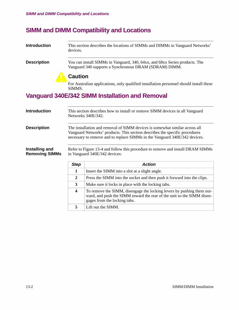
Introduction This section describes the locations of SIMMs and DIMMs in Vanguard Networks’ devices.
Description You can install SIMMs in Vanguard, 340, 64xx, and 68xx Series products. The Vanguard 340 supports a Synchronous DRAM (SDRAM) DIMM.
CautionFor Australian applications, only qualified installation personnel should install these SIMMS.
Vanguard 340E/342 SIMM Installation and Removal
Introduction This section describes how to install or remove SIMM devices in all Vanguard Networks 340E/342.
Description The installation and removal of SIMM devices is somewhat similar across all Vanguard Networks’ products. This section describes the specific procedures necessary to remove and to replace SIMMs in the Vanguard 340E/342 devices.
Installing and Removing SIMMs
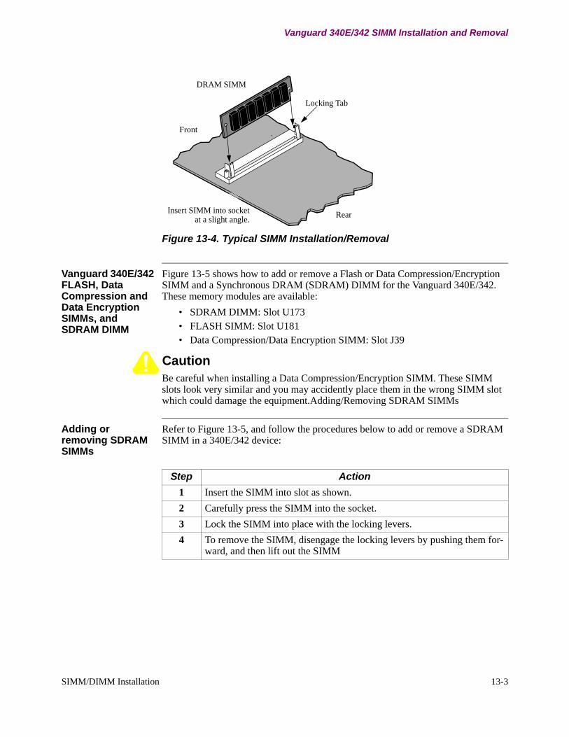
Refer to Figure 13-4 and follow this procedure to remove and install DRAM SIMMs in Vanguard 340E/342 devices:
Step Action1 Insert the SIMM into a slot at a slight angle.2 Press the SIMM into the socket and then push it forward into the clips.3 Make sure it locks in place with the locking tabs.4 To remove the SIMM, disengage the locking levers by pushing them out-
ward, and push the SIMM toward the rear of the unit so the SIMM disen-gages from the locking tabs.
5 Lift out the SIMM.
Front
Rear
DRAM SIMM
Locking Tab
Insert SIMM into socketat a slight angle.
SIMM/DIMM Installation 13-3
Vanguard 340E/342 SIMM Installation and Removal
Figure 13-4. Typical SIMM Installation/Removal
Vanguard 340E/342 FLASH, Data Compression and Data Encryption SIMMs, and SDRAM DIMM
Figure 13-5 shows how to add or remove a Flash or Data Compression/Encryption SIMM and a Synchronous DRAM (SDRAM) DIMM for the Vanguard 340E/342. These memory modules are available:
• SDRAM DIMM: Slot U173• FLASH SIMM: Slot U181• Data Compression/Data Encryption SIMM: Slot J39
CautionBe careful when installing a Data Compression/Encryption SIMM. These SIMM slots look very similar and you may accidently place them in the wrong SIMM slot which could damage the equipment.Adding/Removing SDRAM SIMMs
Adding or removing SDRAM SIMMs
Refer to Figure 13-5, and follow the procedures below to add or remove a SDRAM SIMM in a 340E/342 device:
Step Action1 Insert the SIMM into slot as shown.2 Carefully press the SIMM into the socket.3 Lock the SIMM into place with the locking levers.4 To remove the SIMM, disengage the locking levers by pushing them for-
ward, and then lift out the SIMM

SDRAM DIMM
Locking tabs
Data Compression/Encryption SIMM
Locking levers
FLASH SIMM
13-4 SIMM/DIMM Installation
Vanguard 340E/342 SIMM Installation and Removal
Figure 13-5. Vanguard 340E/342 FLASH, Data Compression/Encryption SIMM, and SDRAM DIMM Installation
Adding/Removing FLASH SIMMs
Refer to Figure 13-5, and follow the procedures below to add or remove a FLASH SIMM in a Vanguard 340E/342:
Step Action1 At a slight angle, insert the SIMM into connector as shown.2 Carefully press the SIMM down, pushing the locking tabs through the
holes. The clips click into place.3 To remove the SIMM, use your fingers to push back the two metal retain-
ing clips and lift out the SIMM.
Adding/Removing Data Compression/Encryption SIMMs
Refer to Figure 13-5, and follow the procedures below to add or remove a Data Compression Encryption SIMM in a Vanguard product:
Step Action1 At a slight angle, insert the SIMM into the connector, lining up the holes
with the tab as shown.2 Carefully press the SIMM down, pushing the locking tabs through the
holes. The clips click into place.3 Lock the SIMM into place with the locking levers.4 To remove the SIMM, use your fingers to push back the two metal retain-
ing clips and lift out the SIMM.
SIMM/DIMM Installation 13-5
Vanguard 64xx Series FLASH, Data Compression, and Data Encryption SIMMs
Vanguard 64xx Series FLASH, Data Compression, and Data Encryption SIMMs
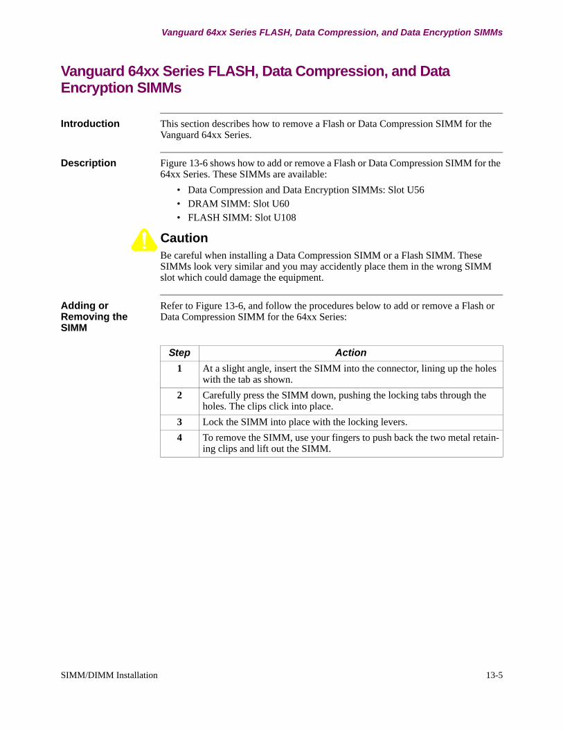
Introduction This section describes how to remove a Flash or Data Compression SIMM for the Vanguard 64xx Series.
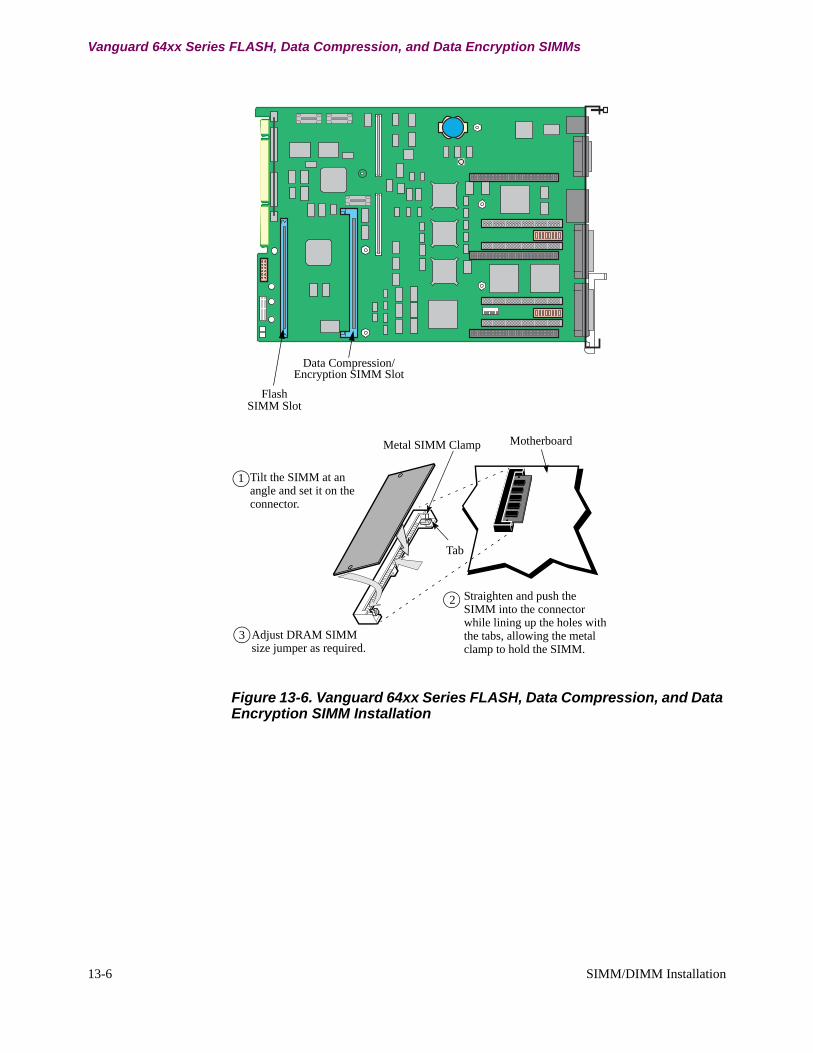
Description Figure 13-6 shows how to add or remove a Flash or Data Compression SIMM for the 64xx Series. These SIMMs are available:
• Data Compression and Data Encryption SIMMs: Slot U56• DRAM SIMM: Slot U60• FLASH SIMM: Slot U108
CautionBe careful when installing a Data Compression SIMM or a Flash SIMM. These SIMMs look very similar and you may accidently place them in the wrong SIMM slot which could damage the equipment.
Adding or Removing the SIMM
Refer to Figure 13-6, and follow the procedures below to add or remove a Flash or Data Compression SIMM for the 64xx Series:
Step Action1 At a slight angle, insert the SIMM into the connector, lining up the holes
with the tab as shown.2 Carefully press the SIMM down, pushing the locking tabs through the
holes. The clips click into place.3 Lock the SIMM into place with the locking levers.4 To remove the SIMM, use your fingers to push back the two metal retain-
ing clips and lift out the SIMM.
Metal SIMM Clamp Motherboard
Tab
1
2
Flash
Data Compression/
SIMM Slot
3
Tilt the SIMM at an angle and set it on the connector.
Adjust DRAM SIMM size jumper as required.
Straighten and push the SIMM into the connector while lining up the holes with the tabs, allowing the metal clamp to hold the SIMM.
Encryption SIMM Slot
13-6 SIMM/DIMM Installation
Vanguard 64xx Series FLASH, Data Compression, and Data Encryption SIMMs
Figure 13-6. Vanguard 64xx Series FLASH, Data Compression, and Data Encryption SIMM Installation
SIMM/DIMM Installation 13-7
Vanguard 68xx Series SDRAM DIMM
Vanguard 68xx Series SDRAM DIMM
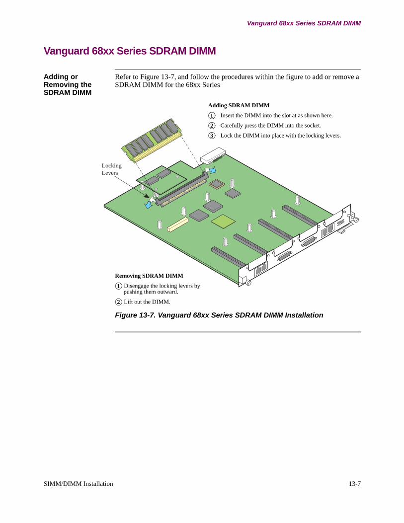
Adding or Removing the SDRAM DIMM
Refer to Figure 13-7, and follow the procedures within the figure to add or remove a SDRAM DIMM for the 68xx Series
Locking
Levers
Adding SDRAM DIMM
Insert the DIMM into the slot at as shown here.
Carefully press the DIMM into the socket.
Lock the DIMM into place with the locking levers.
1
2
3
Removing SDRAM DIMM
Disengage the locking levers by pushing them outward.
Lift out the DIMM.
1
2
Figure 13-7. Vanguard 68xx Series SDRAM DIMM Installation

13-8 SIMM/DIMM Installation
Vanguard 68xx Series SDRAM DIMM
Index-1
Numerics
2-Port Serial Y-cable 1
C
Cabling2-Port Serial Data Card 1
D
DaughtercardDIM 1ISDN BRI-ST 2, 3ISDN BRI-U 1
DaughtercardsOne Port FXS/FXO 1Packaging 4
DIMDCE Port 5DTE Port 5sockets 5
DIM Daughtercard 1DIM devices 4DIM Site Daughtercard 1, 5
DIP switches 3strapping 2
DRAM SIMMsCompatibility 2installation and removal 2
DSU 1adding/replacing 3, 4speeds of 56 kbps 1
DSU Daughtercard 1Dual E&M Daughtercard
cable pinout 3jumper settings 2port assignments 1
E
Enclosureopening 2, 6, 10
F
FT1/FE1 Daughtercardfunctionality 2
I
ISDN BRI-S/T Daughtercard 2, 3ISDN BRI-U Daughtercard 1
L
locking tabs 2
M
Make BusyDCE 2
Multipoint 1
O
One Port FXS/FXO ConnectorsPinouts 1
Opening the enclosure 2, 6, 10
R
RemoteVUConnectors 1
Ring Indicator 2
S
SIMMlocation 2
T
Test Mode 2DTE 2
Two Port FXS DaughtercardInstallation 2Port Assignments 3, 4
V
Vanguard 320termination resistance 6
Vanguard 340Installing Daughtercards 2Removing the Motherboard 2Replacing the Motherboard 2
Vanguard 6400 Seriesdaughtercard support 6Installing Daughtercards 7, 11