vacuum cleaner service manual - semboutique.com · do not dry near fire or direct sunray. do not...
TRANSCRIPT
P/No. : 3828FI5917LSeptember. 2006Printed in Korea
VACUUM CLEANERSERVICE MANUALMODEL : V-KC701HTRCAUTIONBEFORE SERVICING THE UNIT, READ THE "SAFETY PRECAUTIONS" IN THIS MANUAL.
Website http://biz.lgservice.com
-2-
CONTENTS
SAFETY PRECAUTIONS ...............................................................................................................3
CAUTIONS ......................................................................................................................................3
DESCRIPTION ................................................................................................................................4
SPECIFICATIONS...........................................................................................................................4
DISASSEMBLY ...........................................................................................................................5~6
TROUBLE SHOOTING GUIDE...................................................................................................7~9
SCHEMATIC DIAGRAM ..............................................................................................................10
CIRCUIT DIAGRAM ......................................................................................................................11
EXPLODED VIEW ..................................................................................................................12~15
REPLACEMENT PARTS LIST................................................................................................16~17
3828Fi5917L
-3-
SAFETY PRECAUTIONSBEFORE OPERATING THIS VACUUM CLEANER, READ THIS SERVICE MANUAL THOROUGHLY, ANDOBSERVE EACH POINT CAREFULLY.
3828Fi5917L
1. Motor filter(Air Cleaner)1) This filter is reusable.
2) Never use the vacuum cleaner without filter.It may damage the motor.
3) When the light of body is on, wash the motor filter with water.
4) Even if the light is not on, wash the motor filter atleast once 6 months.
NOTE : Reusing of the motor filter.
Never wash the filter in a washing machine or in adishwasher.
Never use hot water for washing the filter.
Reuse the filter after drying it completely in theshade for a day.
Do not dry near fire or direct sunray.
2. Exhaust filter(Washable HEPA filter)1) This filter is reusable HEPA filter.
2) For clean air, this filter must be assembled.
3) Wash the exhaust filter with water once a year.
4) When the light of body is on, wash the exhaust filter with water.
NOTE : Reusing of the exhaust filter.
Never wash the filter in a washing machine or in adishwasher.
Never use hot water for washing the filter.
Reuse the filter after drying it completely in theshade for a half day.
Do not dry near fire or direct sunray.
Do not brush the filter. This will cause permanentlydamage allowing dust to by-pass the filter.
Do not wash the blue side of the filter.
3. Avoid suction such materials as :1) Liquid or wet dust :
Clogs the ventilation holes, reduces the suctionpower significantly and harms the motor.
2) Inflammable liquids such as benzene, alcohol orsolvents.
3) Burning objects such as cigarette butts.
4) Bulky objects such as vinyl, paper etc.
5) Sharp objects such as needles, pins, metal, glass particles etc.
4. AttachmentsNozzle : for cleaning wooden floor, the room floorand carpet.
Crevice Tool : for cleaning any crevice, inside corners or window frames. However, do not use the crevice tool more than 20 minutes because it may cause harm to the motor.
Dusting brush : for cleaning clothes curtains.
5. Close supervision is necessary when thisvacuum cleaner is used by or near children.Children’s carelessness may cause damageto the cleaner or injure persons.
6. Air exhausted from the vacuum cleaner isnormally warm. But if extraordinarily hot airis exhausted, check if the telescopic tube,hose or clean filter is clogged or not.
7. Electric shock could occur if used outdoorsor on wet surfaces.
1. Motor exchange1) Separate the Body Cover and Body Base by
unfastening the screws.
2) After disconnecting the lead wires, replace the old motor with a new one.
2. In case of exchanging other parts. refer to the exploded view.
CAUTIONSBEFORE ATTEMPTING TO SERVICE OR ADJUST ANY PART OF THE VACUUM CLEANER, DISCONNECTTHE ELECTRICAL POWER SUPPLY CORD FROM THE WALL OUTLET.
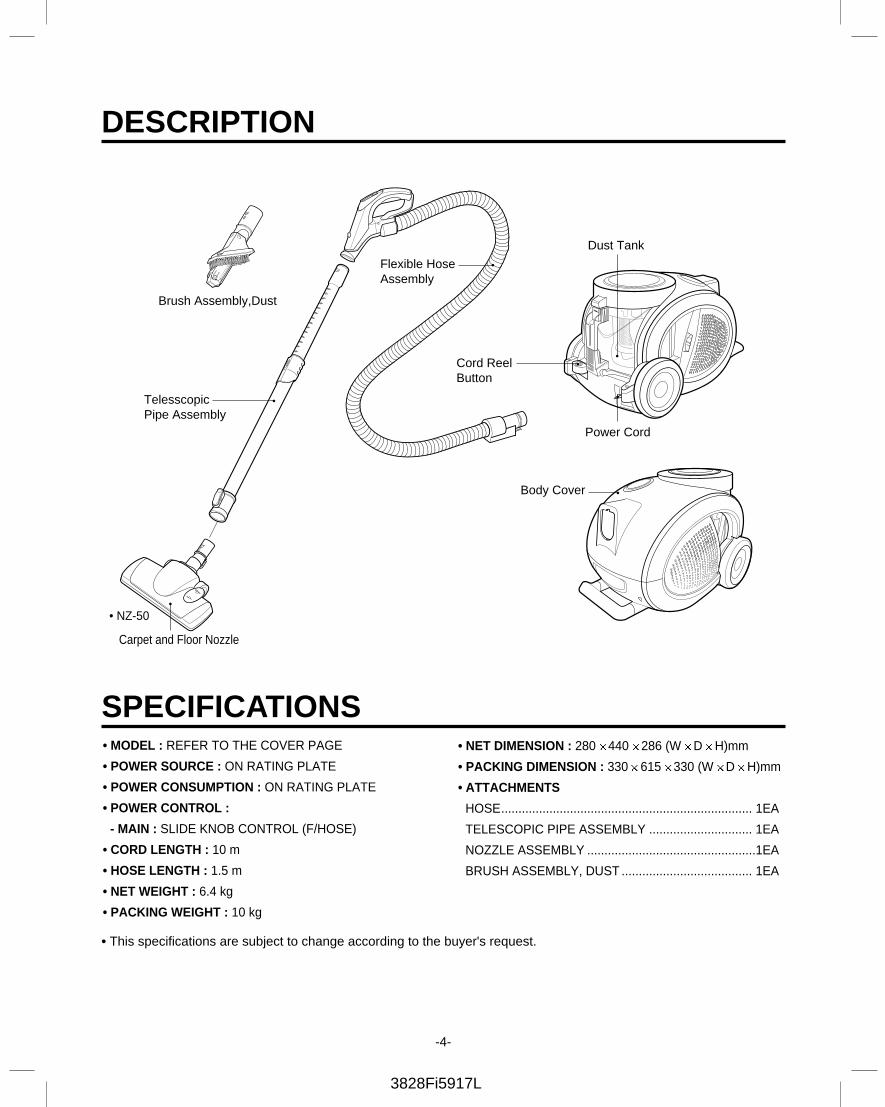
DESCRIPTION
Cord Reel Button
Dust Tank
Body Cover
Power Cord
Flexible Hose Assembly
TelesscopicPipe Assembly
Brush Assembly,Dust
Carpet and Floor Nozzle
• NZ-50
-4-
SPECIFICATIONS
3828Fi5917L
• MODEL : REFER TO THE COVER PAGE
• POWER SOURCE : ON RATING PLATE
• POWER CONSUMPTION : ON RATING PLATE
• POWER CONTROL :
- MAIN : SLIDE KNOB CONTROL (F/HOSE)
• CORD LENGTH : 10 m
• HOSE LENGTH : 1.5 m
• NET WEIGHT : 6.4 kg
• PACKING WEIGHT : 10 kg
• NET DIMENSION : 280 440 286 (W D H)mm
• PACKING DIMENSION : 330 615 330 (W D H)mm
• ATTACHMENTS
HOSE......................................................................... 1EA
TELESCOPIC PIPE ASSEMBLY .............................. 1EA
NOZZLE ASSEMBLY .................................................1EA
BRUSH ASSEMBLY, DUST ...................................... 1EA
• This specifications are subject to change according to the buyer's request.
3828Fi5917L
-5-
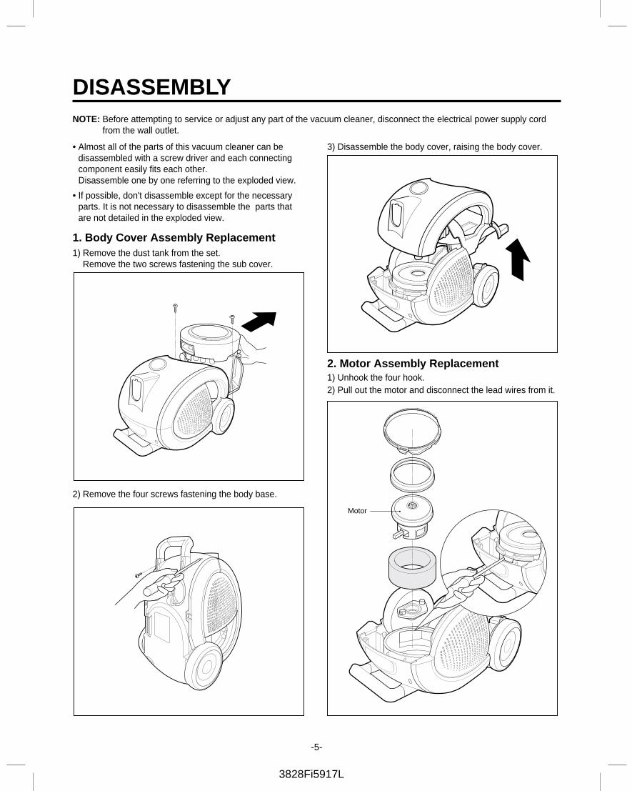
DISASSEMBLY
• Almost all of the parts of this vacuum cleaner can be disassembled with a screw driver and each connectingcomponent easily fits each other. Disassemble one by one referring to the exploded view.
• If possible, don't disassemble except for the necessaryparts. It is not necessary to disassemble the parts thatare not detailed in the exploded view.
1. Body Cover Assembly Replacement1) Remove the dust tank from the set.
Remove the two screws fastening the sub cover.
2) Remove the four screws fastening the body base.
3) Disassemble the body cover, raising the body cover.
2. Motor Assembly Replacement1) Unhook the four hook.2) Pull out the motor and disconnect the lead wires from it.
NOTE: Before attempting to service or adjust any part of the vacuum cleaner, disconnect the electrical power supply cordfrom the wall outlet.
Motor
3828Fi5917L
-6-
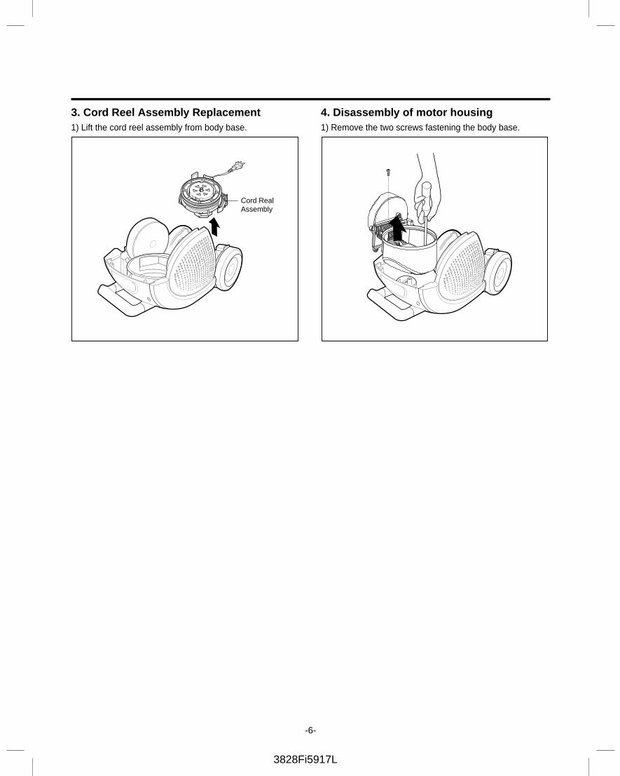
3. Cord Reel Assembly Replacement1) Lift the cord reel assembly from body base.
4. Disassembly of motor housing 1) Remove the two screws fastening the body base.
Cord RealAssembly
3828Fi5917L
-7-
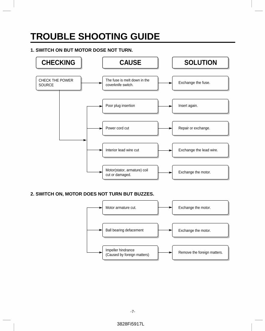
CHECKING
CHECK THE POWERSOURCE
The fuse is melt down in thecoverknife switch. Exchange the fuse.
Poor plug insertion Insert again.
Power cord cut Repair or exchange.
Interior lead wire cut Exchange the lead wire.
Motor(stator, armature) coilcut or damaged.
Exchange the motor.
Motor armature cut. Exchange the motor.
Ball bearing defacement Exchange the motor.
Impeller hindrance(Caused by foreign matters)
Remove the foreign matters.
CAUSE SOLUTION
TROUBLE SHOOTING GUIDE1. SWITCH ON BUT MOTOR DOSE NOT TURN.
2. SWITCH ON, MOTOR DOES NOT TURN BUT BUZZES.
-8-
3828Fi5917L
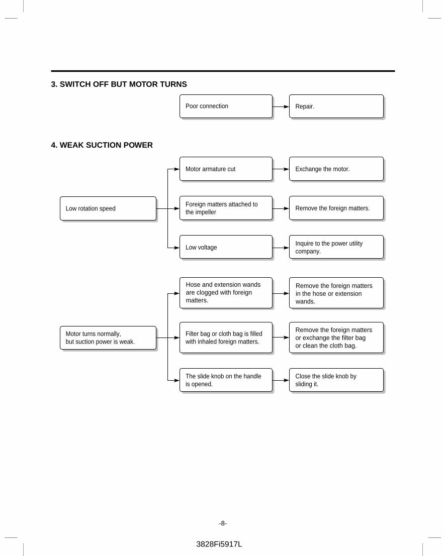
Motor armature cut Exchange the motor.
Foreign matters attached tothe impeller
Remove the foreign matters.
Low voltageInquire to the power utilitycompany.
Hose and extension wandsare clogged with foreign matters.
Remove the foreign mattersin the hose or extensionwands.
Filter bag or cloth bag is filled with inhaled foreign matters.
Remove the foreign matters or exchange the filter bag or clean the cloth bag.
The slide knob on the handleis opened.
Close the slide knob bysliding it.
Poor connection Repair.
Low rotation speed
Motor turns normally,but suction power is weak.
3. SWITCH OFF BUT MOTOR TURNS
4. WEAK SUCTION POWER
3828Fi5917L
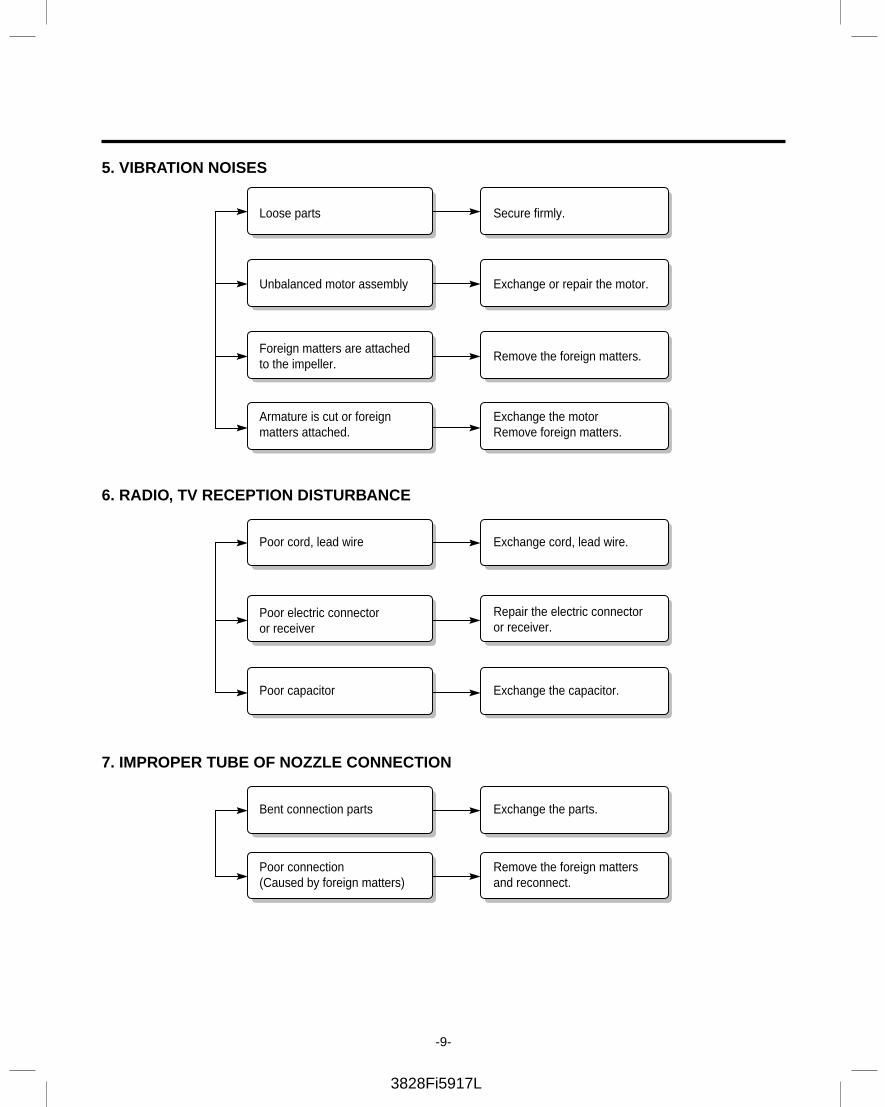
Loose parts Secure firmly.
Unbalanced motor assembly Exchange or repair the motor.
Foreign matters are attachedto the impeller.
Remove the foreign matters.
Poor cord, lead wire Exchange cord, lead wire.
Poor electric connector or receiver
Repair the electric connector or receiver.
Poor capacitor Exchange the capacitor.
Bent connection parts Exchange the parts.
Poor connection(Caused by foreign matters)
Remove the foreign mattersand reconnect.
Armature is cut or foreignmatters attached.
Exchange the motorRemove foreign matters.
-9-
5. VIBRATION NOISES
6. RADIO, TV RECEPTION DISTURBANCE
7. IMPROPER TUBE OF NOZZLE CONNECTION
3828Fi5917L
-10-
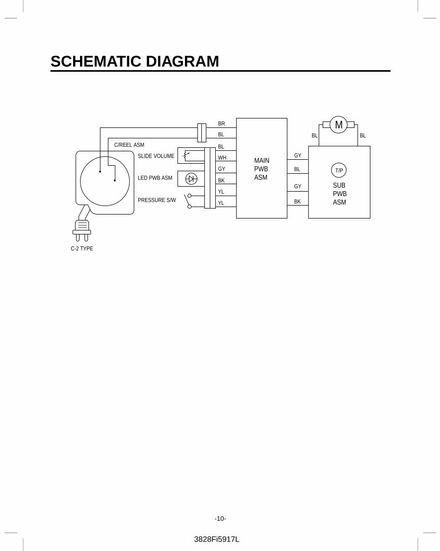
SCHEMATIC DIAGRAM
C-2 TYPE
C/REEL ASM
SLIDE VOLUMEMAINPWBASM
SUBPWBASM
BR
GY
BL
GY
BK
BL
BL
BL BL
WH
GY
YL
YL
BKLED PWB ASM
PRESSURE S/W
M
T/P
3828Fi5917L
-11-
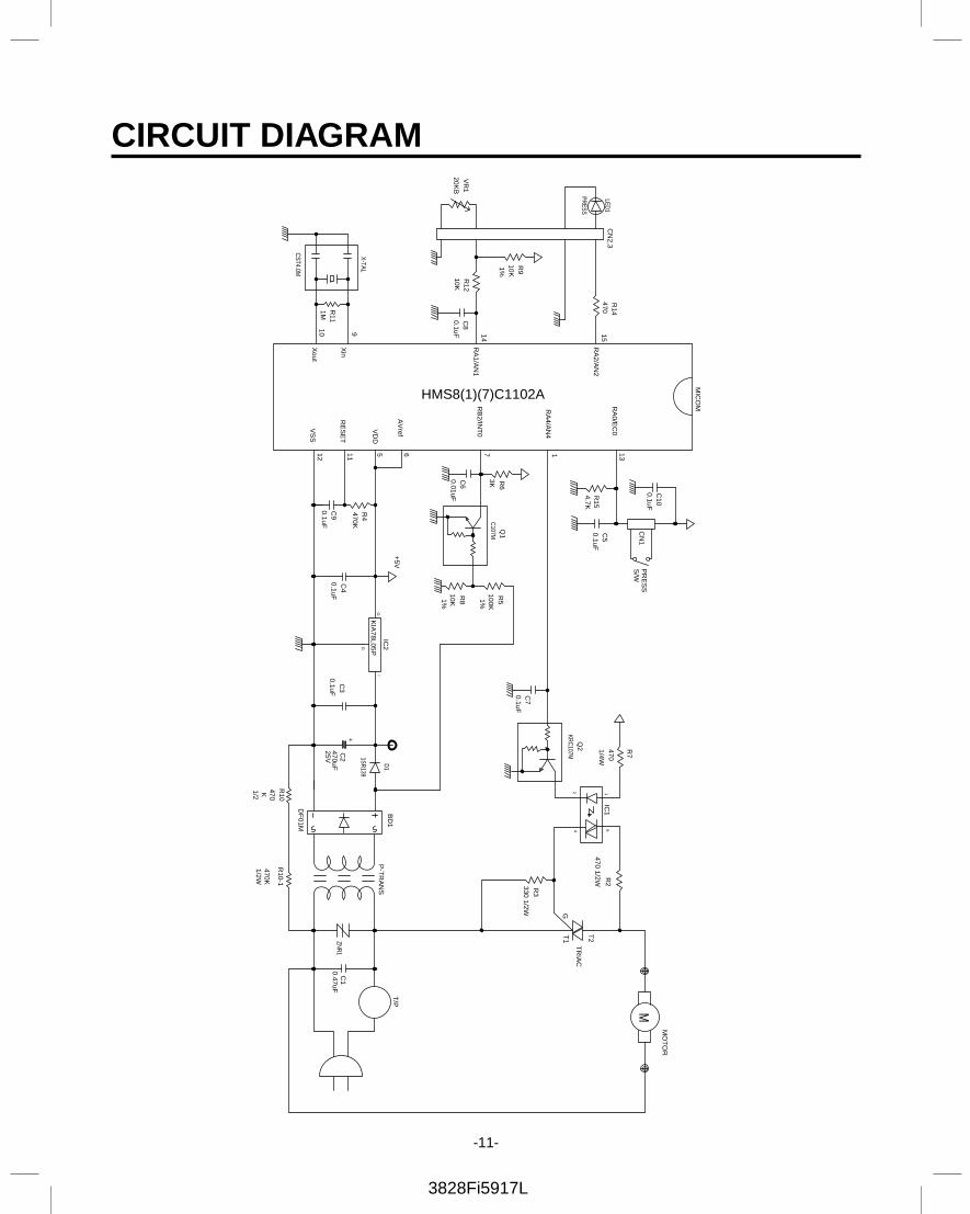
CIRCUIT DIAGRAM
G
+
470K
1/2
R10
470K1/2W
R10-1
M
1SR139
C10
RA
0/EC
0VD
D
AV
ref
VS
S
RE
SE
T
RB
2/INT
0
RA
4/AN
4
X-TAL
CST4.0M
Xout
Xin
1MR
11
10 9
1%10KR
9
VR
120K
B
PRESS
LED1
CN
2,3
HMS8(1)(7)C1102A
RA
1/AN
1R
1210K
0.1uFC
8
14
RA
2/AN
2470R
14
15
0.1uF
470K
12 11
C9
5 6
R4
0.1uFC
4
+5V
C3
0.1uF
IC2
KIA
78L05PO
I
25V470uFC
2
D1
100K1%
10K1%0.01uFC
6
3K7
R6
R8
Q1
C107M
R5
1
4.7KR
15
13
0.1uF
0.1uFC
5
CN
1P
RE
SS
S/W
0.1uFC
7
1/4W
KRC
107MQ
2 R7
470
MIC
OM
ZNR
1
DF
01M
BD
1P
-TR
AN
S
0.47uFC
1
T/P
T2
330 1/2WR
3
470 1/2W
24
1IC
16
GT
1
R2
TR
IAC
MO
TO
R
3828Fi5917L
-12-
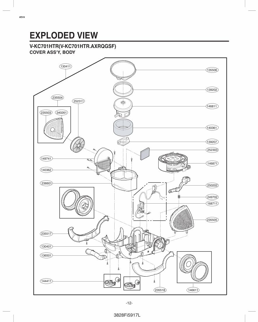
EXPLODED VIEW
235504252311
140362
149741
236601
235517
130401
136501
144411
235518 146611
135506
139202
146811
140361
139207
252303
146871
250202
249702
235505
130411
340261235503
168711
V-KC701HTR(V-KC701HTR.AXRQGSF)COVER ASS'Y, BODY
#EV#
3828Fi5917L
-13-
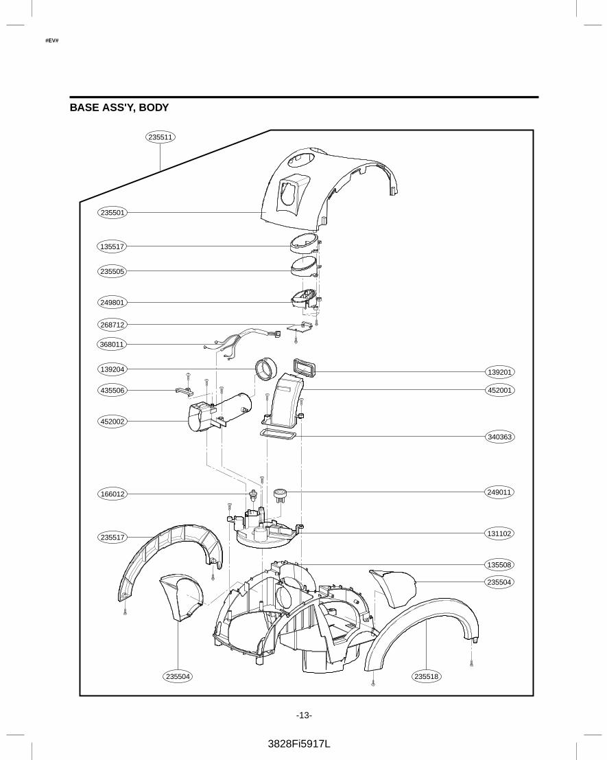
235501
135517
235505
249801
268712
139201
452001
340363
235518
249011
131102
135508
235504
166012
235517
435506
139204
452002
368011
235504
235511
BASE ASS'Y, BODY
#EV#
3828Fi5917L
-14-
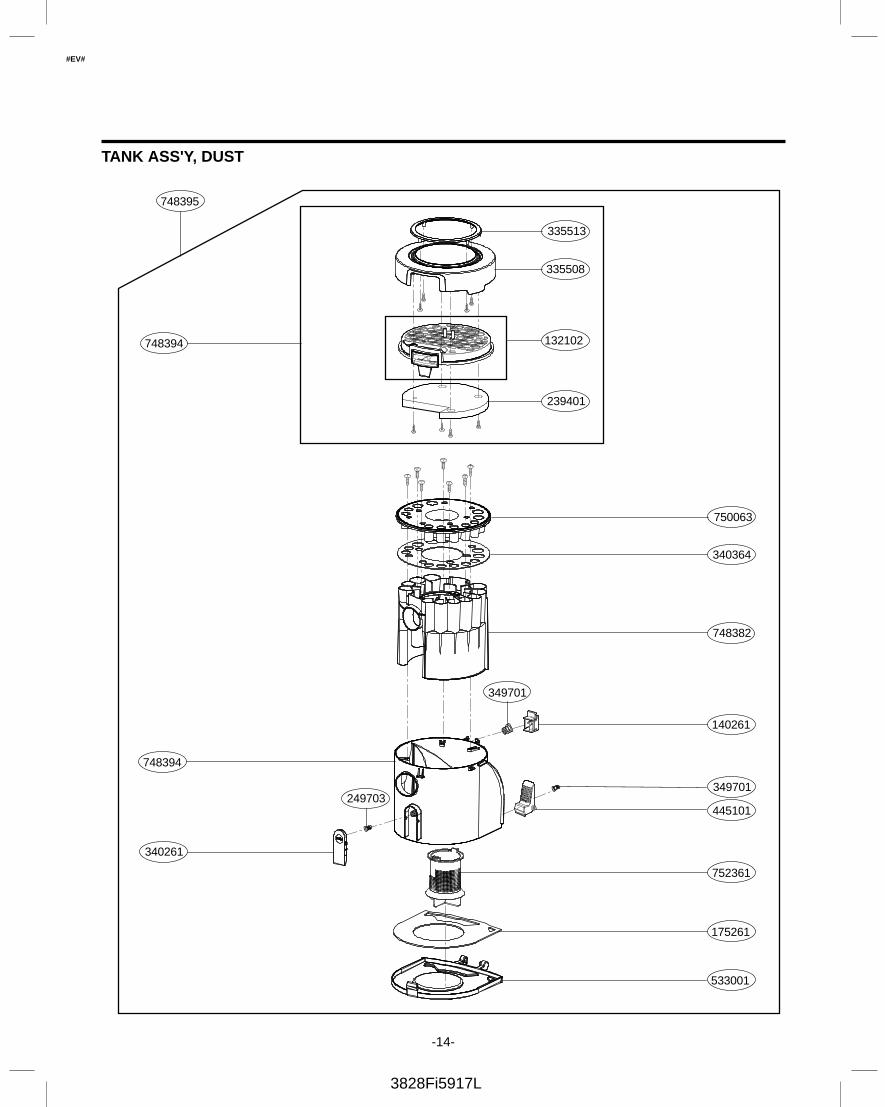
335513
335508
132102748394
239401
750063
340364
748382
752361
140261
349701
445101
349701
175261
340261
249703
748394
533001
748395
TANK ASS'Y, DUST
#EV#
3828Fi5917L
-15-
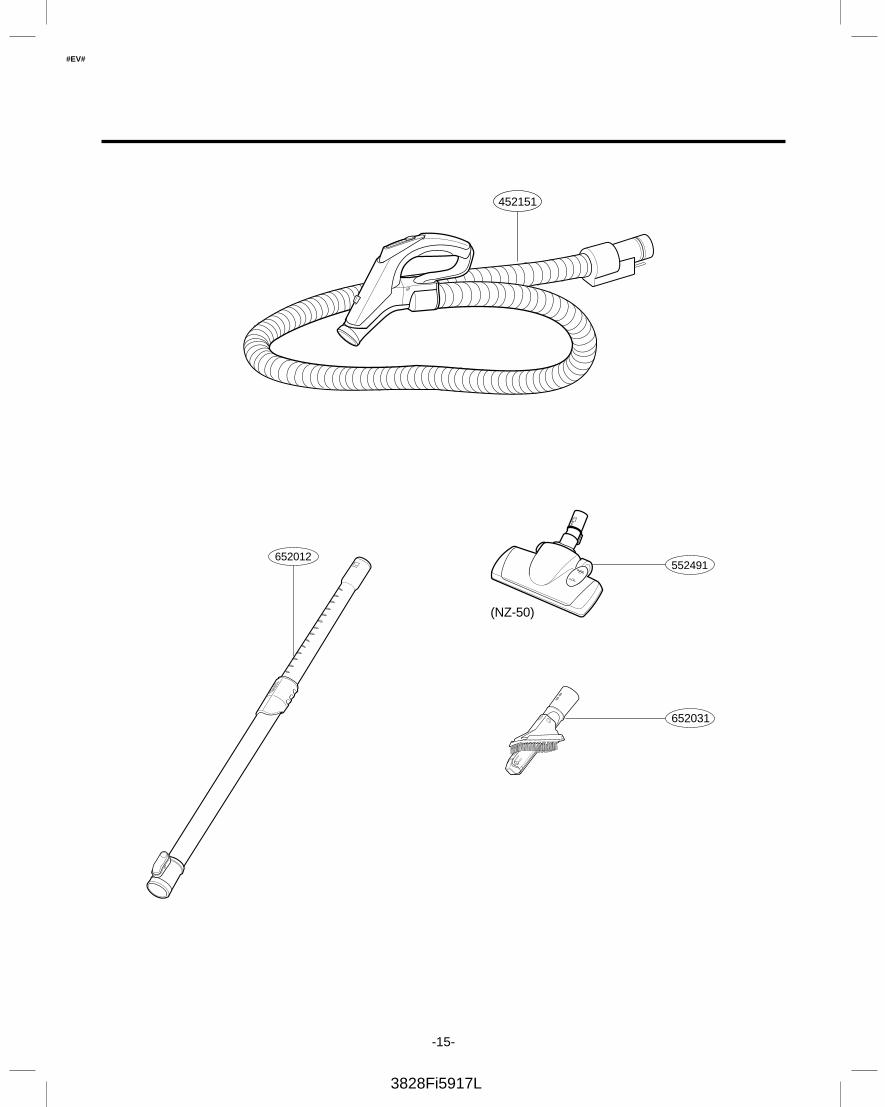
452151
652012552491
(NZ-50)
652031
#EV#
3828Fi5917L
-16-
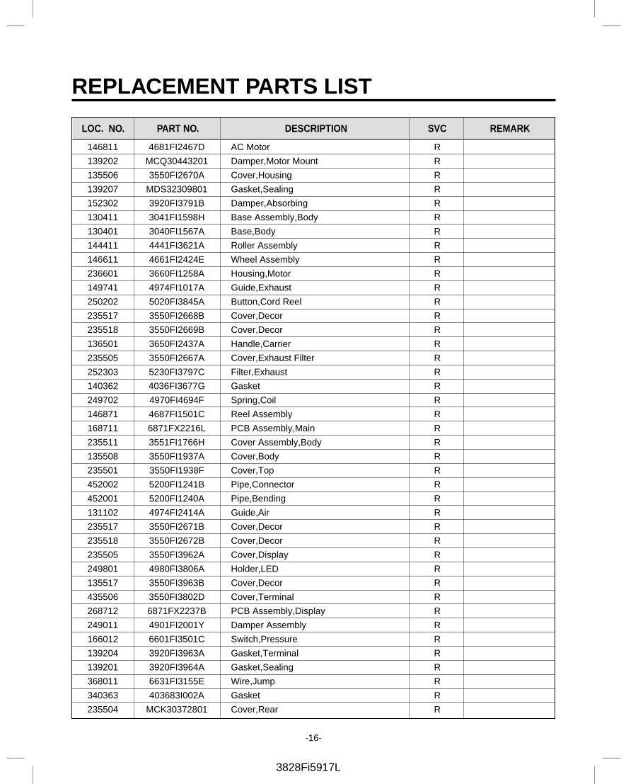
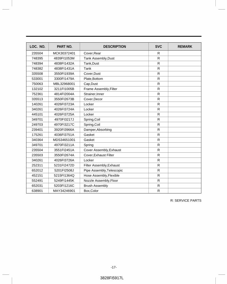
REPLACEMENT PARTS LIST
146811 4681FI2467D AC Motor R
139202 MCQ30443201 Damper,Motor Mount R
135506 3550FI2670A Cover,Housing R
139207 MDS32309801 Gasket,Sealing R
152302 3920FI3791B Damper,Absorbing R
130411 3041FI1598H Base Assembly,Body R
130401 3040FI1567A Base,Body R
144411 4441FI3621A Roller Assembly R
146611 4661FI2424E Wheel Assembly R
236601 3660FI1258A Housing,Motor R
149741 4974FI1017A Guide,Exhaust R
250202 5020FI3845A Button,Cord Reel R
235517 3550FI2668B Cover,Decor R
235518 3550FI2669B Cover,Decor R
136501 3650FI2437A Handle,Carrier R
235505 3550FI2667A Cover,Exhaust Filter R
252303 5230FI3797C Filter,Exhaust R
140362 4036FI3677G Gasket R
249702 4970FI4694F Spring,Coil R
146871 4687FI1501C Reel Assembly R
168711 6871FX2216L PCB Assembly,Main R
235511 3551FI1766H Cover Assembly,Body R
135508 3550FI1937A Cover,Body R
235501 3550FI1938F Cover,Top R
452002 5200FI1241B Pipe,Connector R
452001 5200FI1240A Pipe,Bending R
131102 4974FI2414A Guide,Air R
235517 3550FI2671B Cover,Decor R
235518 3550FI2672B Cover,Decor R
235505 3550FI3962A Cover,Display R
249801 4980FI3806A Holder,LED R
135517 3550FI3963B Cover,Decor R
435506 3550FI3802D Cover,Terminal R
268712 6871FX2237B PCB Assembly,Display R
249011 4901FI2001Y Damper Assembly R
166012 6601FI3501C Switch,Pressure R
139204 3920FI3963A Gasket,Terminal R
139201 3920FI3964A Gasket,Sealing R
368011 6631FI3155E Wire,Jump R
340363 403683I002A Gasket R
235504 MCK30372801 Cover,Rear R
LOC. NO. DESCRIPTION SVC REMARKPART NO.
3828Fi5917L
-17-
235504 MCK30372401 Cover,Rear R
748395 4839FI1053M Tank Assembly,Dust R
748394 4838FI1432A Tank,Dust R
748382 4838FI1431A Tank R
335508 3550FI1939A Cover,Dust R
533001 3300FI1479A Plate,Bottom R
750063 MBL32968001 Cap,Dust R
132102 3211FI1005B Frame Assembly,Filter R
752361 4814FI2004A Strainer,Inner R
335513 3550FI2673B Cover,Decor R
140261 4026FI3723A Locker R
340261 4026FI3724A Locker R
445101 4026FI3725A Locker R
349701 4970FI3217J Spring,Coil R
249703 4970FI3217C Spring,Coil R
239401 3920FI3966A Damper,Absorbing R
175261 4036FI3751A Gasket R
340364 MDS34651001 Gasket R
349701 4970FI3211A Spring R
235504 3551FI2451A Cover Assembly,Exhaust R
235503 3550FI2674A Cover,Exhaust Filter R
340261 4026FI3726A Locker R
252311 5231FI2472D Filter Assembly,Exhaust R
652012 5201FI2508J Pipe Assembly,Telescopic R
452151 5215FI1364Q Hose Assembly,Flexible R
552491 5249FI1445K Nozzle Assembly,Floor R
652031 5203FI1216C Brush Assembly R
638901 MAY34246901 Box,Color R
LOC. NO. DESCRIPTION SVC REMARKPART NO.
R: SERVICE PARTS
-18-
MEMO
3828Fi5917L

-19-
MEMO
3828Fi5917L

MK