utah state capitol building restoration and seismic base ... · utah state capitol building...
TRANSCRIPT

Utah State Capitol Building Restoration and Seismic
Base Isolation
Presented by
Jerod G. Johnson, SE, LEED(AP)
Reaveley Engineers + Associates
for
CSCE Regional Lecture Tour
February 28-29, 2012
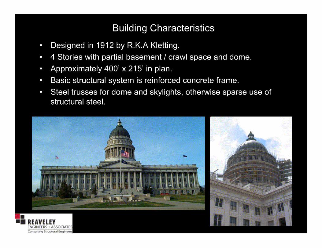
• Designed in 1912 by R.K.A Kletting.
• 4 Stories with partial basement / crawl space and dome.
• Approximately 400’ x 215’ in plan.
• Basic structural system is reinforced concrete frame.
• Steel trusses for dome and skylights, otherwise sparse use of
structural steel.
Building Characteristics
Nonstructural Features
• Stacked Granite Columns on South, East and West Sides.
• Exterior carved/stacked granite cladding.
• Skylights and atrium.
• Pediments and parapets.
• Rotunda and dome.
• Interior tile, marble, other unusually heavy components.
• Unusually heavy overall structural massing. The building is roughly 2 times the weight of a modern office building of comparable space

Primary Findings of Early Studies
• Structural frame is inadequate with respect to the expected seismic motion.
• Inadequate reinforcement in walls, columns and beams to provide ductile
performance.
• Large diaphragm openings in levels 3, 4, attic, roof.
• Non-continuous infills comprised of HCT and URM.
• Exterior cladding backed by URM.
• Lack of bracing for parapets, pediments, and balustrades.
• Window penetrations of dome create ‘soft’ story.
• Dome seismic forces are amplified due to its height.
• Lack of uniform lateral stiffness. Rotunda is stiff, wings are flexible.
• Inadequate anchorage of cladding.

The Need for Seismic Retrofit:
•Primary structure is reinforced concrete beams and columns. Although
innovative in its day, the concrete is lightly reinforced by today’s
standards. Concepts of seismic design did not exist 90 years ago.
•The building is within a very short distance of the active Wasatch Fault.
•Expected seismic performance (pre-retrofit) was extremely poor.
Significant earthquake would likely have meant loss of life and loss of the
building.
Top of existing
column in attic
of Capitol
Owner Performance Expectations:
Life Safety (FEMA 356 Basic Safety Objective)
Historic Preservation
Results of Studies:
The expected seismic performance was
extremely poor with a high likelihood for loss of
life and property.

As Is Building Model - 30x Amplification(Click on image to start animation)

Potential Retrofit Schemes
• Increase the strength, stiffness and ductility of the
existing building.
• Reduce the seismic demand with a base isolation
system.
• Use a combination of these approaches.

Potential Retrofit Scheme: Add Strength to Existing Building
EARTHQUAKE FORCE
Building
Strength
Earthquake
Intensity
Lack of Seismic Capacity

EARTHQUAKE FORCE
Building
Strength
Earthquake
Intensity
Improved
Building
Strength
Increased
Earthquake
Intensity
Potential Retrofit Scheme: Add Strength to Existing Building

EARTHQUAKE FORCE
Building
Strength
Earthquake
Intensity
Improved
Building
Strength
Increased
Earthquake
Intensity
This approach was deemed not feasible:
•Overall forces would have increased.
•New shear walls would not have fit within the
architectural/historic layout.
•Far more rigorous treatment of all nonstructural elements
and components would have been required.
•Historic character of building would have been
compromised
Potential Retrofit Scheme: Add Strength to Existing Building
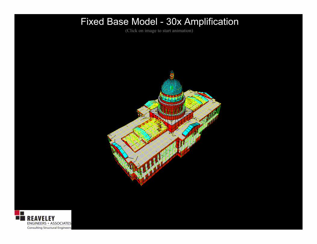
Fixed Base Model - 30x Amplification(Click on image to start animation)

The Solution
Seismic Base Isolation was selected as the
preferred solution since most readily met
performance objectives while being sensitive to
historic preservation and costs.
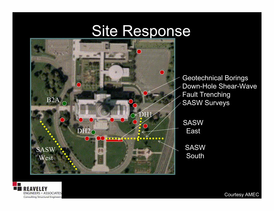
Site ResponseSite Response
Geotechnical Borings
Down-Hole Shear-Wave
Fault Trenching
SASW SurveysB2A
SASW
West
SASW
South
SASW
East
DH1
DH2
Courtesy AMEC

Source-to-Site GeometrySource-to-Site Geometry
Courtesy AMEC
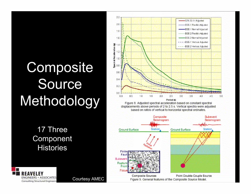
Composite
Source
Methodology
Composite
Source
Methodology
17 Three
Component
Histories
Courtesy AMEC

Utah State Capitol Fault-Normal Spectra
0.0
0.5
1.0
1.5
2.0
2.5
3.0
3.5
4.0
0.0 0.5 1.0 1.5 2.0 2.5 3.0 3.5 4.0 4.5 5.0
Period (s)
Spectral Acceleration (g)
1 sa2 5
2 sa2 5
3 sa2 5
4 sa2 5
5 sa2 5
6 sa2 5
7 sa2 5
Mean FN
M+1s FN
10% 50-yr Adj
BSE-2 Adj
UTAH STATE CAPITOL
Scenario M 7 Earthquake
One Fault; South Epicenter; Deep Focus
Fault-Normal Spectra; 5% Damping
Period shift provided by base isolation
Courtesy AMEC

Base Isolation Fundamental Concept
•A base isolator is a bearing mechanism upon which a building rests.
It is very stiff vertically but very limber horizontally.
•A group of base isolators tied together beneath a building creates a
seismic base isolation system.
•Because a base isolation system is very limber horizontally it can
dramatically increase the fundamental period of the global system
(base isolation system and building structure).
•An increase in period generally results in a decrease of earthquake
forces.
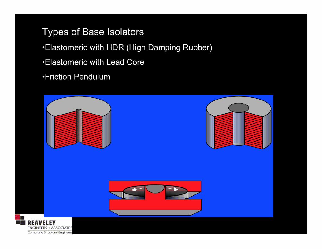
Types of Base Isolators
•Elastomeric with HDR (High Damping Rubber)
•Elastomeric with Lead Core
•Friction Pendulum

Isolator Anatomy
• Note– Each isolator weighs approximately 5000 pounds.
~20”

Isolator Anatomy – Why Steel Plates?
Note: depicted deflection is true
to scale

Isolator Anatomy – Why Lead Core?
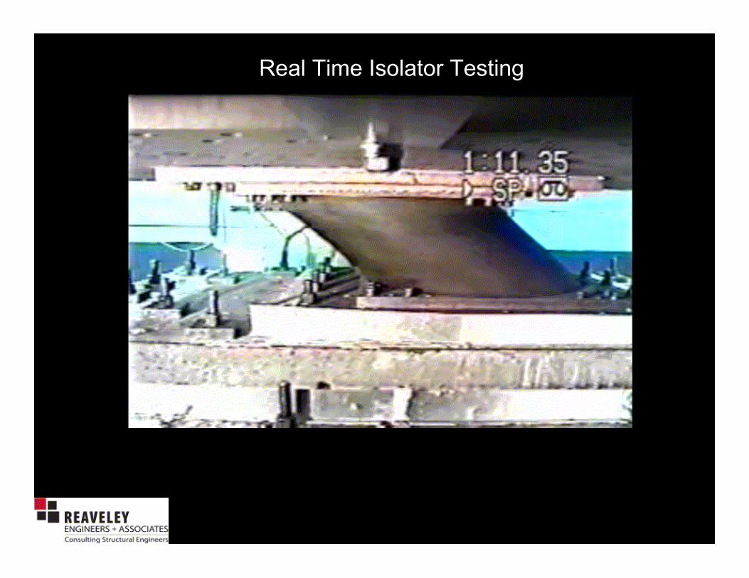
Real Time Isolator Testing

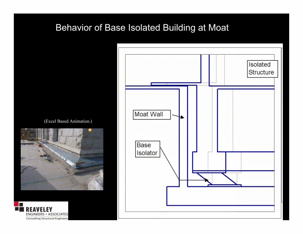
Behavior of Base Isolated Building at Moat
(Excel Based Animation.)
Behavior of Base Isolated Building at Moat
(Excel Based Animation.)

Isolator Prototype Testing
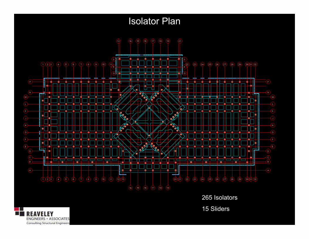
Isolator Plan
265 Isolators
15 Sliders

Load Transfer Scheme(s)
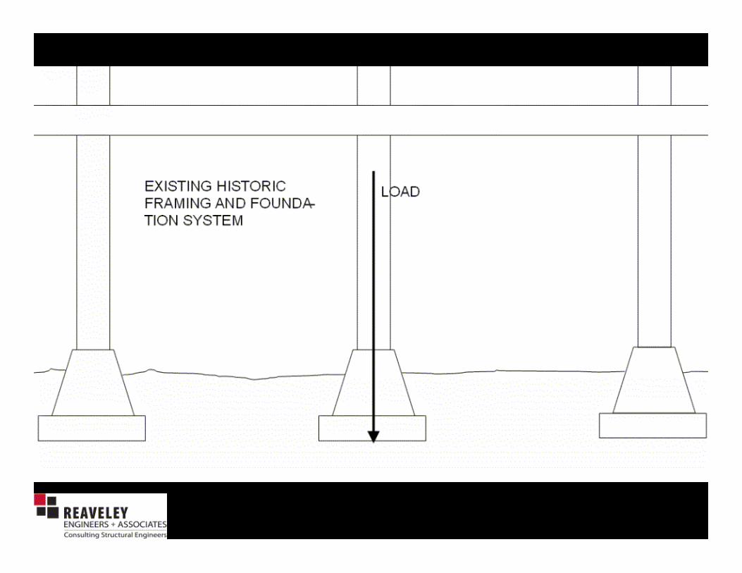


COLUMNS
PREPARED FOR
“KEYING” EFFECT

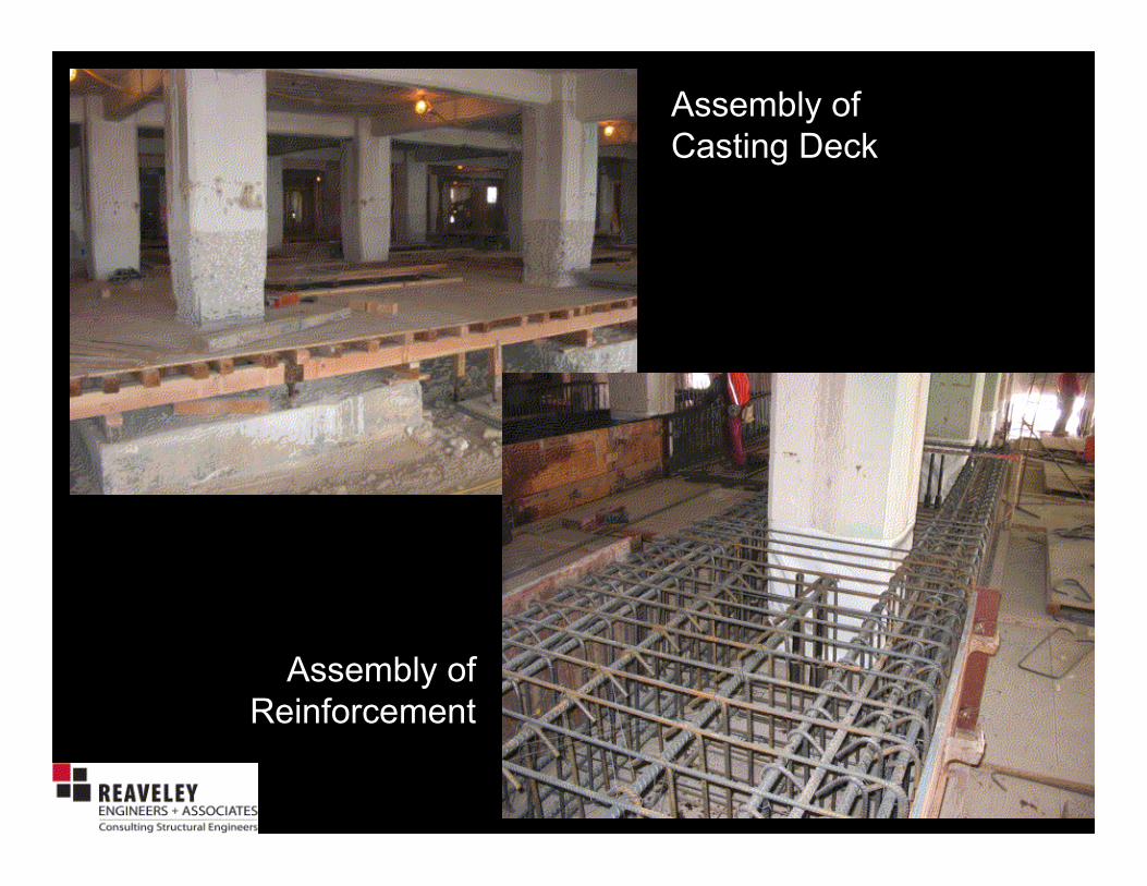
Assembly of
Casting Deck
Assembly of
Reinforcement

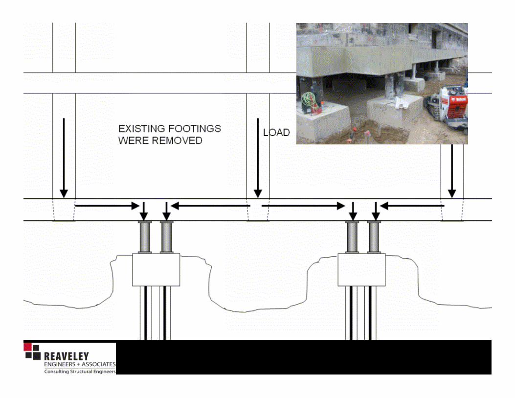


Footing Removal

Installation of First Isolator – May 16, 2005

Isolator Placement w/ Flat Jack

Locking Plate Removal

Load Transfer Scheme(s)

Load Transfer Scheme(s)
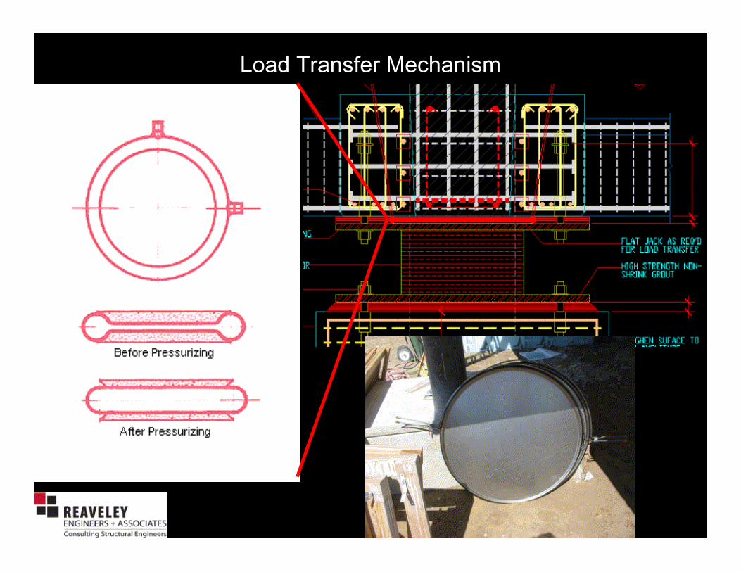
Load Transfer Mechanism

Load Transfer Scheme – Mockup and Testing


Isolator Installation at Rotunda

Isolator Installation at Rotunda
Courtesy Forell
Elsesser Engineers

Isolator Installation at Rotunda

Isolator Installation at Rotunda

Isolator Installation at Rotunda

Isolator Installation at Rotunda

Isolator Installation at Rotunda

Isolator Installation at Rotunda
Courtesy Forell
Elsesser Engineers

Isolator Installation at Rotunda
Courtesy Forell
Elsesser Engineers

Photos courtesy of
Forell Elsesser
Engineers

New Perimeter
and Interior
Shear Walls
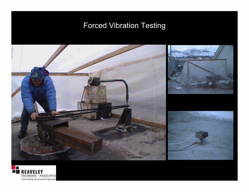
Forced Vibration Testing
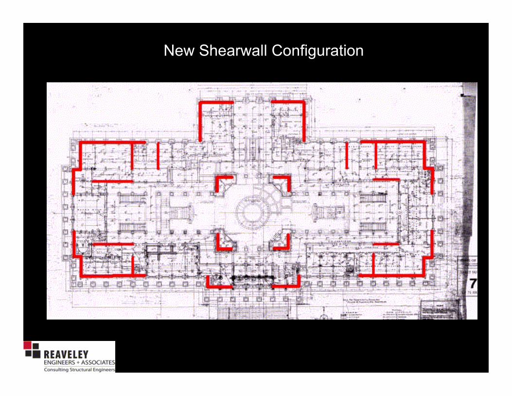
New Shearwall Configuration

New Shearwalls

Shear Walls at Perimeter
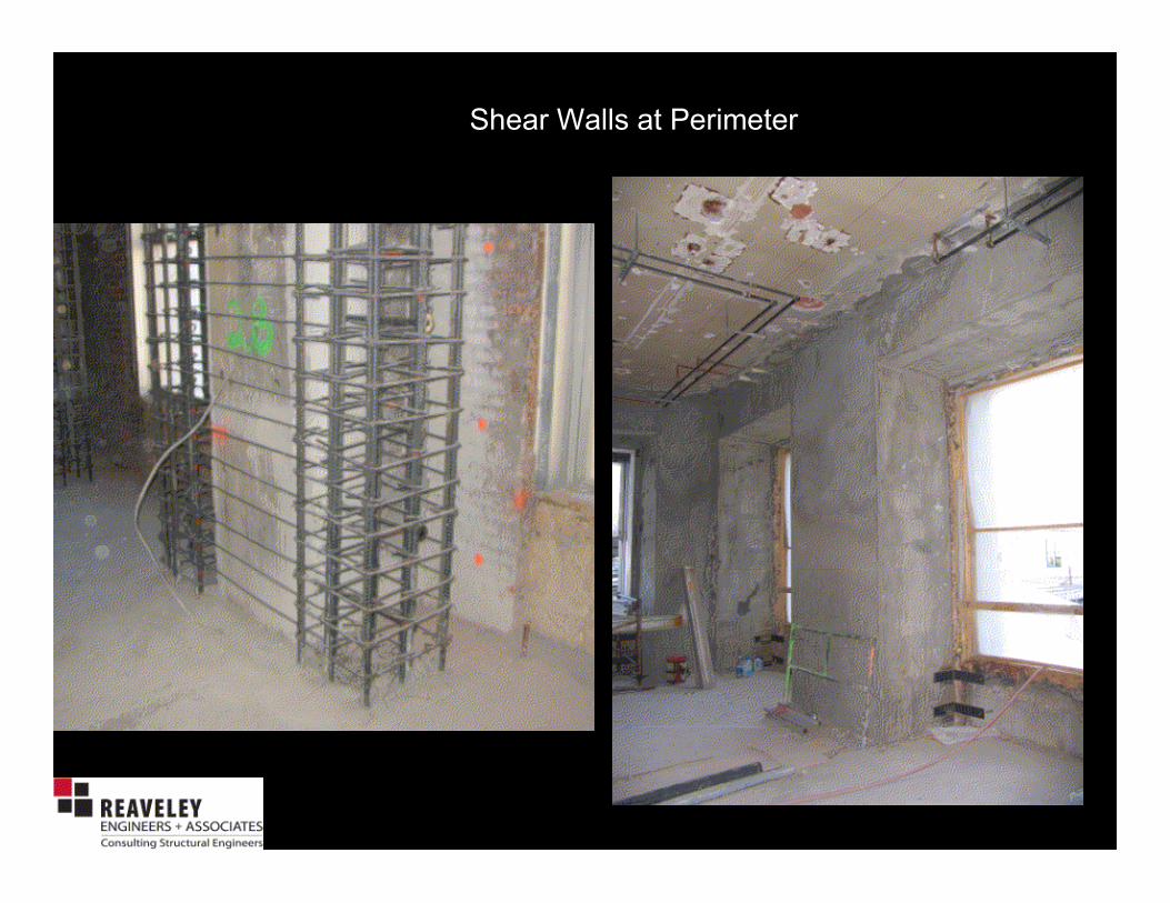
Shear Walls at Perimeter

Isolator Installation at Rotunda

Base Isolated Model - 30x Amplification(Click on image to start animation)
How does Base Isolation benefit the Utah State Capitol?
• Horizontal Seismic Accelerations are reduced by approximately 75% to 80% for a large earthquake.
• Preservation of Life.
• Preservation of Utah Heritage.

How does Base Isolation benefit the Utah State Capitol?EARTHQUAKE FORCE
Building
Strength
Earthquake
Intensity
Lack of Seismic Capacity

How does Base Isolation benefit the Utah State Capitol?EARTHQUAKE FORCE
Building
Strength
Earthquake
Intensity
Improved
Building
Strength
Reduced
Earthquake
Intensity

Credits:
Owner: Utah State Capitol Preservation Board, David H. Hart, Architect of the Capitol
CMGC: Jacobsen Hunt Joint Venture
Architect: Capitol Restoration Group, a joint venture of VCBO Architecture, MJSA Architects, Schooley
Caldwell Associates
Structural Engineer: Reaveley Engineers + Associates, Forell Elsesser Engineers
Mechanical Engineer: Spectrum, Heath
Electrical Engineer: Spectrum
Geotechnical/Geoseismic Engineer: AMEC
This presentation provided by Reaveley Engineers + Associates