ut3 february march 2014
DESCRIPTION
The magazine of the Society for Underwater TechnologyTRANSCRIPT

UT2 February March 2014
1
UT3February March 2014
T H E M A G A Z I N E O F T H E S O C I E T Y F O R U N D E R W A T E R T E C H N O L O G Y
CommunicationsUnderwater Vehicles

2
UT2 February March 2014
Underwater Vehicles

UT2 February March 2014
3
ContentsNews
February March 2014
Vessels
Diving
Underwater Communications
Underwater Vehicles
11 14 16
20 24 26
28 29 30 32
36 40 41 43 44
47 48 55 5750

4
UT2 February March 2014
Published by UT2 Publishing for and on behalf of the Society for Underwater Technology. Reproduction of UT2 in whole or in part, without permission, is prohibited. The publisher and the SUT assumes no responsibility for unsolicited material, nor responsibility for content of any advertisement, particularly infringement of copyrights, trademarks, intellectual property rights and patents, nor liability for misrepresentations, false or misleading statements and illustrations. These are the sole responsibility of the advertiser. Opinions of the writers are not necessarily those of the SUT or the publishers.
Editor: John Howes [email protected]
Editorial Assistant: Tim O'Shenko
Sub EditorEmily Boddy
Production: Sue Denham
ISSN: 1752-0592
Launching an ROVImage: Kongsberg Maritime
UT2 February March 2014
1
UT2January February 2013
T H E M A G A Z I N E O F T H E S O C I E T Y F O R U N D E R W A T E R T E C H N O L O G Y
PipelinesUnderwater Vehicles
Equipment
Underwater Vehicles
Equipment
58 59 60
60 62
57
64 66
66 67Society for Underwater
Technology1 Fetter Lane
London EC4A 1BR
+44 (0) 1480 370007
Vol 9 No 1

UT2 February March 2014
5
DEFINING SUBSEA SERVICES
From exploration to decommissioning, Acteoncompanies bring technical ingenuity and a drive forfresh thinking to every stage of offshore activity.This approach to the subsea service market is justone example of how we're defining, shaping andleading subsea services.
Discover a fresh approach to subsea services at www.acteon.com/subsea3
SUBSEA SERVICES(SUHB-SEE SUR-VIS-ES) Definitive
THE PROVISION OF SPECIALISTEQUIPMENT, SERVICES ANDPERSONNEL, COMPLEMENTARY TO THE CAPABILITIES OF VESSELOWNERS AND SUBSEACONSTRUCTION COMPANIES.

6
UT2 February March 2014
EMAS' Subsea Services division (EMAS AMC) been awarded projects worth a total of US$80millionincluding options.
The scope of these projects cover a large spectrum of subsea work, including the decommissioning and towing of an FPSO in Asia and the deployment of an Inspection, Maintenance and Repair (IMR) vessel in the Americas. Work for a majority of the contracts is expected to commence by the first half of 2014.
The Group began the year with strong top-line growth with operational profitability, registering a 22% jump to US$339.8 million in revenue compared to the corresponding period in 2013. The Group’s subsea orderbook stands at more than US$1.4 billion, and is still tendering for some US$9 billion in projects worldwide.
FMC Technologies has signed a three-year contract with Pemex for the manufacture and supply of surface wellheads to support its drilling and well maintenance programmes in the Gulf of Mexico.
FMC Technologies' scope of supply includes surface wellheads and production trees, as well as installation and supervision services for Pemex's operations in its Southwest Marine Region of the Gulf of Mexico. The equipment will be supplied from FMC Technologies' operations in Mexico.
Aker Solutions is to provide engineering services, procurement and management assistance for as many as 10 years at the Johan Sverdrup development in the Norwegian North Sea.
The accord includes front-end engineering design (FEED) work, with a value of NOK 650 million, as well as an option for the development's first phase. It also has additional options for work in later phases.
Johan Sverdrup is estimated to hold between 1.8 billion and 2.9 billion barrels of oil equivalent.
Technip has been awarded two ultra-deep water contracts by Petrobras, for the supply of flexible pipes for the Sapinhoá Norte field and I5 at Lula field (former Tupi field), located in the Santos Basin pre-salt area (Brazil), at a water depth of up to 2500m.
The combination of both contracts covers the supply of approximately 100km of flexible pipes for oil production, gas lift, and gas injection. It also includes related equipment for the pre-salt area, to be installed on the
News2013 UK and Norway ReviewEnergy analyst Wood Mackenzie’s annual UK upstream oil and gas review concluded that 2013 was a mixed year with increased capital investment being set against the backdrop of project delays, production underperformance and poor exploration success.
It pointed, however, to promising new fields coming due onstream in 2014.
“Last year capital investment was at its highest level since the mid-1970s," said Lindsay Wexelstein, Head of UK Upstream Research. We anticipate £21.3 billion (US$33 billion) will be spent on capital investment across 2013 and 2014.
“Stretched resources, however, also led to project delays. Only13 new fields were brought onstream in 2013 (438 million barrels of oil equivalent (mmboe) of recoverable reserves), which was lower than the 21 expected at the start of the year.” A similar number of fields and volume of reserves is expected onstream in 2014. So what does 2014 hold for the UK’s upstream sector?
“The UK’s upstream sector should look to 2014 with cautious optimism. We forecast 14 new fields with 438 mmboe to be brought onstream," said Wexelstein.
Norway's upstream sector showed no signs of slowing down in 2013, with high levels of development spend, asset deals, exploration activity, and a record NKr 176 billion (US$30 billion) capital investment – a 30% increase on 2012. Wood Mackenzie expects 2014 to be a key year. Spend will remain high while the larger companies optimise their portfolios. High demand and busy development activity have driven up costs globally in recent years, but the effect was particularly prevalent in Norway in 2013.
Malcolm Dickson, Senior Norway Upstream analyst for Wood Mackenzie said: "The level of cost inflation across the upstream sector in Norway led to a series of major cost revisions resulting in challenging economic margins for several large scale developments last year."
The Norwegian government also introduced the first petroleum tax increase in 20 years. "This came as a big surprise to Norway's upstream industry and although the marginal rate remained at 78%, capital uplift was reduced - hitting marginal fields the hardest, such as the Johan Castberg field."
"Overall discovered reserves were down 30% compared with 2012 despite an additional 14 exploration wells. 18 discoveries yielded 715 million barrels of oil equivalent (mmboe) last year with two of the most significant finds, Lundin's Gohta and OMV's Wisting, in the Barents," said Dickson. The impact of the 2013 petroleum tax on marginal projects will also become clearer," he concluded.
Johan Sverdrup
Pemex
EMAS Contracts
Petrobras

UT2 February March 2014
7
2013 UK and Norway Review
AD
0104
7OSS Designed to deliver the highest level of reliability. Built with technology that assures it. With the
subsea control module from OneSubsea™, you benefi t from a proven track record of 99.9% uptime since entering the market in 2000. This reliability is a result of the OneSubsea unrivaled qualifi cation process, with industry-leading design, superior quality components and built-in redundancies.
From subsea processing to production systems, OneSubsea delivers industry-leading control systems to meet your future technology challenges. Visit www.onesubsea.com/leadingdesign
OneSubsea Control Systems: High availability for continuous production
operating uptime. Proven reliability.
ONESUB-121_Controls_UT2 Q4.indd 1 11/19/13 6:23 PM

8
UT2 February March 2014
floating production storage and offloading (FPSO) units, Cidade de Angra dos Reis and Cidade de Ilhabela.
The gas injection top risers are designed for high internal pressure, using the Teta profile developed by Technip’s R&D team in its Flexi France plant in Le Trait (France).
The gas injection top riser, together with the majority of the scope will be manufactured in Flexibras Açu , starting production in the first quarter of 2014 in line with previously announced plans.
The remaining scope will be manufactured in Flexibras Vitória. Technip’s operating center in Rio de Janeiro (Brazil) will perform the engineering and project management.
GE will supply Statoil with its fifth generation SemStar5 Subsea Electronics Module to upgrade and extend the life of the subsea production control system for the Troll B field.
GE designed, built and installed the original Troll B subsea production system in 1995. The new Troll B subsea control system will upgrade all wells on manifolds D, E, F, G and H.
The SemStar5 will be designed to be backwards-compatible with the existing system and will replace the reliable, but now obsolete technology that was provided originally.
FMC Technologies has contracted Aveon Offshore to fabricate more than 5000t of subsea structures for the Egina field development offshore Nigeria.Operator Total Upstream Nigeria awarded FMC the engineering, procurement, construction, and commissioning contract for the subsea production systems.
Aveon is performing fabrication at its 240 000m2 (2.58 million ft2) yard in Rumuolumeni, near Port Harcourt. First steel was cut in December. Load-out and sail-away of the subsea structures is expected to get under way during the second half of 2015.
Technip has been awarded by Statoil a substantial contract for future intervention services on the Asgard Subsea Compression Stations. Ranking among the largest developments on the Norwegian continental shelf, the Asgard field lies on the Haltenbank in the Norwegian Sea, about 200km off Norway. The Asgard subsea compression facility is the world’s first project of its kind.
The awarded project corresponds to an extension of both the dedicated vessel and equipment, developed under the current Asgard Subsea Compression Marine Operations contract. The new contract will also cover the use of this vessel for
SemStar
Aveon
Asgard
Endeavour has announced that production has recommenced at Rochelle, a gas-condensate field, in the U.K. North Sea.
The East Rochelle E2 well is on production and flowing to the Scott Platform. The West Rochelle W1 well is anticipated to restart production in a few days.
Production from the two wells is expected to exceed the available capacity limits across the Scott Platform.
Saipem has won new Engineering & Construction offshore contracts in Indonesia and in the Republic of Congo, for a total amount of approximately $520 million.
In Indonesia, Eni has awarded a consortium led by Saipem the EPCI contract for a new built barge Floating Production Unit (FPU) for the Jangkrik Complex Project development.
The consortium is formed by Hyundai Heavy Industries Ltd (HHI) and the joint venture between Saipem, Tripatra Engineers & Constructors and Chiyoda. The total contract value for the project is $1.1 billion.
The new build spread-moored FPU will have a treating capacity of 450MMSCFD of gas plus condensates and the scope of work includes engineering, procurement, fabrication of the FPU and the installation of a mooring system as well as hook-up, commissioning and assistance to the start-up.
The Jangkrik FPU project will be carried out from the Saipem Execution Centre in Jakarta. The topsides fabrication activities will be carried out in Saipem’s Karimun Island Yard, also located in Indonesia, while the hull will be fabricated in HHI’s offshore yard in Ulsan in South Korea. The FPU will be delivered at site ready for surf hook-up in 34 months.
This contract is in line with Saipem’s strategy of growth in particular in the Floaters construction in specific geographic areas, such as Asia Pacific and Africa, where the company can leverage on its local well established and unique availability of fabrication yards.
Saipem
Endeavour
UT2 February March 2014
9
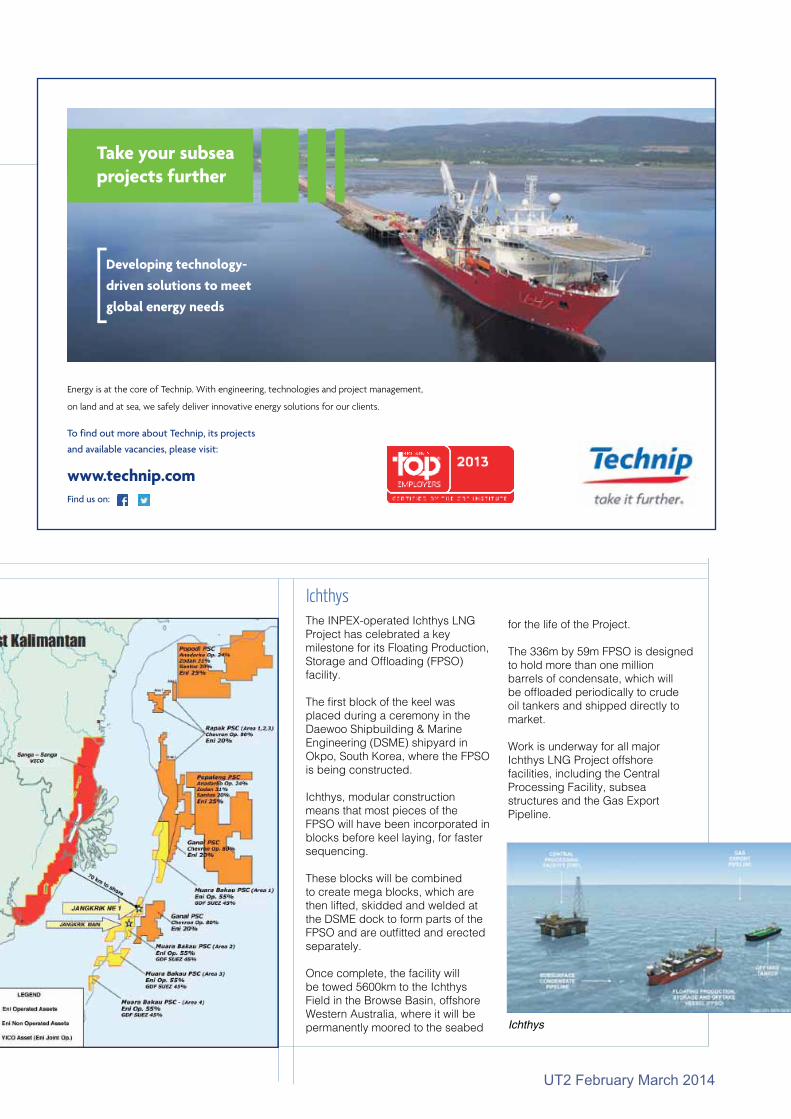
The INPEX-operated Ichthys LNG Project has celebrated a key milestone for its Floating Production, Storage and Offloading (FPSO) facility.
The first block of the keel was placed during a ceremony in the Daewoo Shipbuilding & Marine Engineering (DSME) shipyard in Okpo, South Korea, where the FPSO is being constructed.
Ichthys, modular construction means that most pieces of the FPSO will have been incorporated in blocks before keel laying, for faster sequencing.
These blocks will be combined to create mega blocks, which are then lifted, skidded and welded at the DSME dock to form parts of the FPSO and are outfitted and erected separately.
Once complete, the facility will be towed 5600km to the Ichthys Field in the Browse Basin, offshore Western Australia, where it will be permanently moored to the seabed Ichthys
Ichthysfor the life of the Project.
The 336m by 59m FPSO is designed to hold more than one million barrels of condensate, which will be offloaded periodically to crude oil tankers and shipped directly to market.
Work is underway for all major Ichthys LNG Project offshore facilities, including the Central Processing Facility, subsea structures and the Gas Export Pipeline.
Saipem
Take your subseaprojects further
Energy is at the core of Technip. With engineering, technologies and project management,
on land and at sea, we safely deliver innovative energy solutions for our clients.
www.technip.com Find us on:
To find out more about Technip, its projects
and available vacancies, please visit:
Developing technology-
driven solutions to meet
global energy needs

10
UT2 February March 2014
floating production storage and offloading (FPSO) units, Cidade de Angra dos Reis and Cidade de Ilhabela.
The gas injection top risers are designed for high internal pressure, using the Teta profile developed by Technip’s R&D team in its Flexi France plant in Le Trait (France).
The gas injection top riser, together with the majority of the scope will be manufactured in Flexibras Açu , starting production in the first quarter of 2014 in line with previously announced plans.
The remaining scope will be manufactured in Flexibras Vitória. Technip’s operating center in Rio de Janeiro (Brazil) will perform the engineering and project management.
GE will supply Statoil with its fifth generation SemStar5 Subsea Electronics Module to upgrade and extend the life of the subsea production control system for the Troll B field.
GE designed, built and installed the original Troll B subsea production system in 1995. The new Troll B subsea control system will upgrade all wells on manifolds D, E, F, G and H.
The SemStar5 will be designed to be backwards-compatible with the existing system and will replace the reliable, but now obsolete technology that was provided originally.
FMC Technologies has contracted Aveon Offshore to fabricate more than 5000t of subsea structures for the Egina field development offshore Nigeria.Operator Total Upstream Nigeria awarded FMC the engineering, procurement, construction, and commissioning contract for the subsea production systems.
Aveon is performing fabrication at its 240 000m2 (2.58 million ft2) yard in Rumuolumeni, near Port Harcourt. First steel was cut in December. Load-out and sail-away of the subsea structures is expected to get under way during the second half of 2015.
Technip has been awarded by Statoil a substantial contract for future intervention services on the Asgard Subsea Compression Stations. Ranking among the largest developments on the Norwegian continental shelf, the Asgard field lies on the Haltenbank in the Norwegian Sea, about 200km off Norway. The Asgard subsea compression facility is the world’s first project of its kind.
The awarded project corresponds to an extension of both the dedicated vessel and equipment, developed under the current Asgard Subsea Compression Marine Operations contract. The new contract will also cover the use of this vessel for other Inspection, maintenance and repair (IMR)
and construction work, whether for the Asgard field or for other licenses in Statoil’s portfolio on the Norwegian continental shelf.
DE
FMC
Technip
GDF SUEZ has achieved first gas production from its Juliet field. The subsea development lies on the western flank of the Southern Gas Basin, 39km East of the Lincolnshire coastline in the United Kingdom.
Initial gas has been produced from the West well, the first of two wells to be drilled. The second well (Juliet East) is expected to come on-stream imminently. At plateau, the wells will produce approximately 80 million ft3 of gas per day (800 million m3/year or 5 million of barrels of oil equivalent (Mboe) per year).
Produced gas is being transported by a 22km pipeline to the Pickerill A platform and then transported onshore via their existing export pipeline to the Theddlethorpe gas terminal.
Juliet was discovered by GDF SUEZ E in December 2008 by vertical well 47/14b-10 which found a dry gas accumulation. The Juliet reservoir is considered to be fully appraised Rotliegendes Leman Sandstone reservoir with gross associated reserves of 11.6 Mboe. The field lies in Block 47/14b.
The company has also started oil production from its Amstel field via a newly installed Q13a-A production platform off the Dutch coast.
The high quality light crude oil is transported through a newly-laid 25km long pipeline to the existing TAQA operated P15 platform, north-west of the Q13a-A platform.
The oil is treated on the P15 oil and gas processing facilities before it is transported further through an existing pipeline to a refinery in the Port of Rotterdam. Amstel is expected to produce at plateau 15 000b/d oil, with an expected field production life of 10 years.
The Q13a-A oil production platform is the first GDF SUEZ installed oil producing platform in the Netherlands. Power is supplied to the Q13a-A platform by a 14km long submarine high-voltage cable, connected to the onshore grid, providing renewable electricity offshore. The platform is secured to the seabed with suction anchors and has electrically driven submersible pumps in the production wells at a depth of 2km.
Julia and Amstel
Tel: +44 (0) 1803 869292 [email protected] our element
Serving the world of Hydrography & Oceanography
in our element
•Tide Gauges•Sound Velocity•Current Meters•CTD & Multi-Parameter
•Echo Sounders & Bathymetry•Wave Recorders•Telemetry Instruments•Ocean Engineering

UT2 February March 2014
11
Julia and Amstel
Subsea connector specialist First Subsea has been awarded a contract by EMAS AMC to supply diverless bend stiffener connectors for risers and umbilicals connected to the turret moored, Gaza Floating Storage and Offloading (FSO) vessel, offshore Libya.
In total, four First Subsea Type 2 bend stiffener connectors (BSCs) will be used to connect three flexible risers (14.75in and 10in) and a dynamic umbilical to the turret.
The BSC connection comprises a ball and taper connector attached to a bend stiffener, which is pulled into a pre-machined, compact I-tube built into the turret. The connector is self-energising and self-aligning, and features First Subsea’s Automatic Release Clamp (ARC) enabling both diverless and ROVless riser and umbilical connections.
The Gaza FSO will replace the existing Sloug FSO in the Bouri field located 120km North West of Tripoli, Libya. The field includes a central processing platform DP4 and satellite platform DP3 in water depths of 170m.
Riser Connectors for Gaza FSOLankhorst Ropes has been awarded a contract by Dana Petroleum to provide Gama 98 polyester mooring lines for the Western Isles Development FPSO).
Given the weather conditions in the North Sea, and relatively shallow water depth, the cylindrically shaped FPSO will use a semi-taut leg mooring system. It will be moored with 14 polyester mooring lines in three clusters of 4, 4 and 6 lines at 250m water depth. Two clusters will have longer lines to the prevailing weather that, together with seabed chain, will provide the lateral restoring force needed to keep the production vessel on station.
The Gama 98 polyester rope tethers are made from high efficiency, parallel laid sub-rope cores within an outer braided jacket. During manufacture all of the sub-ropes are monitored to ensure they all have equal tension and length, ensuring a 100% torque free rope.
Western Isles
Gama 98 polyester mooring lines
Tel: +44 (0) 1803 869292 [email protected] our element
Serving the world of Hydrography & Oceanography
in our element
•Tide Gauges•Sound Velocity•Current Meters•CTD & Multi-Parameter
•Echo Sounders & Bathymetry•Wave Recorders•Telemetry Instruments•Ocean Engineering
Release clamp

12
UT2 February March 2014
BP has announced the start-up of Na Kika Phase 3, a project supporting BP’s strategy of growing high-margin production at four BP-operated hubs in the deepwater Gulf of Mexico.
The first Na Kika Phase 3 well began oil production on February 19, with a second well expected to start up in the second quarter.
The project includes the drilling and
completion of the two new wells, the addition of subsea infrastructure to tieback to the Na Kika platform and new equipment to allow increased production from an existing well at the site. It will utilize available production capacity at the Na Kika hub.
Na Kika Phase 3 is BP’s third new major upstream project to begin production so far in 2014, following the earlier start-ups of the Chirag Oil
project in Azerbaijan and the Mars B project in the Gulf of Mexico. BP expects to start-up a further three upstream projects through the rest of 2014.
“The Na Kika Phase 3 project demonstrates BP’s ongoing commitment to the deepwater Gulf of Mexico and highlights our portfolio's ability to unlock value for investors while also delivering vital energy
BP Starts up Na Kika Phase 3

UT2 February March 2014
13
resources to the United States,” said Richard Morrison, Regional President of BP’s Gulf of Mexico business.
The Na Kika semi-submersible platform is located about 140 miles southeast of New Orleans in over 6,000 feet of water. BP is the operator of Na Kika and holds a 50 percent working interest, with Shell holding the remaining 50 percent
stake. Production from Na Kika first began in 2003.
BP currently has a multi-billion investment program underway in the deepwater Gulf of Mexico.
It plans to concentrate future activity and investment in the Gulf on growth opportunities around its four major operated production hubs – Thunder Horse, Na Kika,
Atlantis and Mad Dog -- as well as on significant exploration and appraisal opportunities within its leading leasehold position in the US offshore region. BP also plans to continue investment in its non-operated production hubs, including Mars, Ursa and Great White.

14
UT2 February March 2014
Johan Sverdrup
Johan Sverdrup field

UT2 February March 2014
15
Statoil has decided on a concept for the first development phase. The field will consist of four installations powered from shore.
Johan Sverdrup is among the largest oil fields on the Norwegian shelf, and will at peak contribute with 25% of the production from the Norwegian shelf. The giant field is expected to start production in late 2019. The field lifetime will be 50 years, with an anticipated plateau production of 550 000–650 000 barrels of oil equivalent/day (boe/d) field capacity.
The partners have decided on power from shore for the Johan Sverdrup field in the first phase, which will reduce total CO2 emissions from the Utsira High area by 60-70%.
“This is historic. We have not made a concept selection for a field this size since the 1980s,” says Arne Sigve Nylund, executive vice president for development and production in Norway.
The field will be developed in multiple phases. The design capacity of the first phase is
315 000 barrels of oil equivalents per day field capacity with an expected production between 315 000 and 380 000 boe/d in the early phase. Pre-drilling of wells will contribute to a rapid production ramp-up.
Investments in the first phase are estimated at between NOK 100-120 billion. These include the field centre, wells, export solutions for oil and gas, and power supply.
The estimates also include contingencies and provisions for market adjustments. In addition, the first phase will facilitate measures for improved oil recovery.
The partners are working continuously to lower the investment level for the first phase.
The field centre in the first phase comprises a process platform, drilling platform, riser platform and living quarter, and has been designed so as to facilitate future development. The installations have steel jackets that are linked by bridges. The water depth is approximately 120m in the area.
Johan Sverdrup phase 1 will be supplied with power from shore with a transformer on Kårstø delivering direct current to the riser platform, ensuring an estimated 80MW.
As part of the plan for development and operations, scheduled to be delivered in early 2015, alternative power solutions for the future phases will be described. One of the alternatives will be power from shore to the whole Utsira High area based on updated power requirements.
“This alternative, if selected, has the potential to capture more than 90% of the total CO2 emissions from this area,” says Reinertsen.
The export solution for oil and gas from Johan Sverdrup is based on transport to shore through dedicated pipelines.
The oil will be transported to the Mongstad terminal in Hordaland county. The gas will be transported via Statpipe to Kårstø in Rogaland county for processing and transport onward.
By harnessing the combined power of three of their AA252 Boomer Plates to provide a single pulse, the Applied Acoustics’ S-Boom System is re-defining the boundaries of shallow seismic surveying. Already recognised for producing high resolution seabed profiles, the fusion of these three transducers delivers a source level high enough to significantly increase sub-bottom penetration without loss of data quality.
+44 (0)1493 440355 : [email protected] : www.appliedacoustics.com
S-Boom Geophysical Systems
Shallow water seismic reflection surveysDeep penetration >200mtrUltra high resolution <0.25mtrClean, stable, repeatable pulse signatureSingle and multi channel streamer compatible

16
UT2 February March 2014
The installation of the 3000t offshore mast crane aboard the Lewek Constellation has been recently completed by means of Huisman China’s new 2400t quayside crane. The quayside crane, also known as the ‘Skyhook’, installed the 3000t offshore mast crane in a two lifts within a three day period.
The Lewek Constellation will leave Huisman China in April and is due to arrive at Huisman Schiedam mid year for the installation of the 800mt Multi-lay pipelay tower.
The 2400mt ‘Skyhook’ is capable of lifting 2400t at 30m outreach or 200t load at 90m outreach. It can travel along the 380m long quayside, and is capable of travelling this distance with a load of 2400t in its “super ballast” main lift configuration.
Previously, the ‘Skyhook’ was used to install two 900mt Heavy Lift Mast Cranes for BigLift’s ‘Happy Sky’.
Constellation Crane
News

UT2 February March 2014
17
The installation of the 3000t offshore mast crane aboard the Lewek Constellation has been recently completed by means of Huisman China’s new 2400t quayside crane. The quayside crane, also known as the ‘Skyhook’, installed the 3000t offshore mast crane in a two lifts within a three day period.
The Lewek Constellation will leave Huisman China in April and is due to arrive at Huisman Schiedam mid year for the installation of the 800mt Multi-lay pipelay tower.
The 2400mt ‘Skyhook’ is capable of lifting 2400t at 30m outreach or 200t load at 90m outreach. It can travel along the 380m long quayside, and is capable of travelling this distance with a load of 2400t in its “super ballast” main lift configuration.
Previously, the ‘Skyhook’ was used to install two 900mt Heavy Lift Mast Cranes for BigLift’s ‘Happy Sky’.
Constellation Crane

18
UT2 February March 2014
Reef Subsea today announced a change in its ownership structure with private equity company HitecVision acquiring all of the shares of GC Rieber Shipping.
The change enables Reef Subsea to move forward under the strong ownership of HitecVision to grow Reef Subsea into a leading provider of integrated services including subsea construction & IMR, installation and trenching of cables and umbilical’s, and seabed dredging & excavation.
Reef Subsea has for the vessels Polar King or Polar Prince from GC Rieber Shipping. These vessels will remain within Reef Subsea fleet until completion of respective firm.
DeepOcean has entered into a five and a half year charter agreement starting March 2016 for a new build installation vessel. This key enabler will enhance DeepOcean’s current service offerings in the SURF (Subsea Umbilicals Risers & Flowlines) segment in the Greater North Sea area.
The new vessel will be owned by Østensjø Rederi and is of SALT 304 design. Key vessel dimensions are; a length of 149.8m, a width of 27m, and 2300 m2 of total deck space.
The vessel is specially designed and equipped to suit the Greater North Sea market with the fuel saving environmentally friendly Siemens BlueDrive PlusC propulsion control technology and DP3 positioning system. The mission equipment will be a 150T dual tensioner vertical lay system and a 3000t carousel situated below deck.
The 400t active heave compensated knuckle boom main crane has extended reach and can lift
Deep Ocean
ReefKleven has signed a contract with Olympic Shipping for the building of an IMR vessel of MT 6021 design. The contract value is around NOK 400 million, and the vessel will be delivered from Kleven Verft in March 2015.
The Marin Teknikk design is new and developed in cooperation with the ship owner Olympic, focusing on efficient and environmentally friendly solutions. The vessel is equipped with an offshore crane, ROV hangars, and with significant accommodation capacity.
Kleven has also signed a contract with Rem Offshore for the building of a PSV specially designed to operate in challenging arctic conditions.
The type VS 485 MK III ARCTIC design includes a number of features for ice prevention and de-icing, and hull and propulsion systems will have ICE-1B class.
The vessel is designed by Wärtsila Ship Design
Kleven
Type VS 485 MK III ARCTIC design
Deep Ocean vessel
Vessels
UT2 February March 2014
19
600t in double fall mode. The accommodation facilities will have a capacity of 140 persons.
“In the last two years we have hired approximately 450 new employees, upgraded our owned and chartered vessel fleet, increased the number of mission equipment to 33 ROVs and 17 trenchers,” said Bart Heijermans, Chief Executive Officer of DeepOcean Group Holding.
We currently operate 11 vessels in our home market, the Greater North Sea, managed by our talented employees in Norway, UK and the Netherlands.
DOF Subsea AS has been awarded several contracts, with a total value of approx. NOK 150 million. In the Atlantic region, DOF Subsea has been awarded a call-off con-tract for 2014 by Statoil Petroleum AS under an existing Survey Frame Agreement.
The call-off covers a minimum 4 months' work including seabed map-ping, pipeline inspection, lay sup-port and assorted light construction services.
The work will be carried out on vari-ous fields primarily in the Norwegian part of the North Sea using the spe-cialized RSV Geosund. The Geosund has performed similar work under the same Frame Agreement in 2012 and 2013. The charter agreement for the vessel Ocean Protector has been extended by 6 months by the charterer Austral-ian Customs and Border control and the vessel will be on firm charter until year-end 2014.
DOF Subsea contracts
Fugro has won a contract from DOF ASA for the provision of precise sat-ellite positioning for the entire DOF fleet of more than 70 vessels glob-ally. The contract is valid for a firm five years with two optional years and also includes the new vessels in DOF’s continuously expanding fleet.
Fugro Positioning
Visit us on:UK • NORTH AMERICA • BRAZIL
Visit us on Stand J400
Outstanding Applications
at Oceanology 2014 11 – 13 March
Gemini NBI sonar image of a cable being trenched >
Image courtesy of Reef Subsea Dredging & Excavation
Reliable imaging and ancillary equipment.
We understand your underwater needs.
#dredging #excavation
Visit: www.tritech.co.uk to discover more.
20
UT2 February March 2014
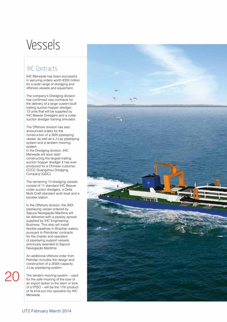
IHC Merwede has been successful in securing orders worth €350 million for a wide range of dredging and offshore vessels and equipment.
The company’s Dredging division has confirmed new contracts for the delivery of a large custom-built trailing suction hopper dredger, 13 units that will be supplied by IHC Beaver Dredgers and a cutter suction dredger training simulator.
The Offshore division has also announced orders for the construction of a 300t pipelaying vessel, as well as a J-Lay pipelaying system and a tandem mooring system.In the Dredging division, IHC Merwede will soon start constructing the largest trailing suction hopper dredger it has ever produced for a Chinese customer, CCCC Guangzhou Dredging Company (GDC).
The remaining 13 dredging vessels consist of 11 standard IHC Beaver cutter suction dredgers, a Delta Multi Craft standard work boat and a booster station.
In the Offshore division, the 300t pipelaying vessel ordered by Sapura Navegação Marítima will be delivered with a pipelay spread supplied by IHC Engineering Business. This ship will install flexible pipelines in Brazilian waters, pursuant to Petrobras’ contracts for the charter and operation of pipelaying support vessels, previously awarded to Sapura Navegação Marítima.
An additional offshore order from Petrofac includes the design and construction of a 2000t capacity J-Lay pipelaying system.
The tandem mooring system – used for the safe mooring of the bow of an export tanker to the stern or bow of a FPSO – will be the 17th product of its kind put into operation by IHC Merwede.
IHC Contracts
Trailing suction hopper dredger
Vessels

UT2 February March 2014
21

22
UT2 February March 2014
DeepOcean has been awarded the contract for inspection of the Nord Stream gas export pipelines in the Baltic Sea by Nord Stream. The Contract is for two years. With a total capacity in the order of 55billion m3/year, the two 48in Nord Stream pipelines from Russia to Germany constitute one of the biggest offshore gas transmission pipeline systems in the world.
The contract is for two years in 2014 and 2015 and includes the full external inspection of the two pipelines using ROV and ROTV methodologies. DeepOcean plans to use its vessel Deep Vision for the 2014 campaign. The expected duration of work is 4-6 months each year.
Nord Stream
Vessels

UT2 February March 2014
23Deep Vision

24
UT2 February March 2014
Petrofac has placed all critical path lump-sum orders to build its new proprietary design Petrofac JSD 6000 deepwater derrick lay vessel, which will be available for construction and installation activities in early 2017.
The vessel contract award includesl Shipyard for hull and marine: ZPMC, Chinal Electrical and control systems: Kongsberg Maritime, l 2000 J-Lay tower: IHC Engineering l 5000t main and 4 deck cranes: NOVl Two deepwater 750 mt tonne winches: Remazel l 600t S-Lay tensioners and pipe handling: Remacut.
The vessel is based on a unique innovative design which integrates the J-Lay, S-Lay and derrick functions and will provide Petrofac with access to high-end turnkey opportunities in the high growth deepwater and SURF markets, and expand access to shallow water EPCI projects.
Petrofac JSD 6000
Vessels

UT2 February March 2014
25

26
UT2 February March 2014
PROMAR has ordered two Platform Supply Vessels from Damen Shipyards Group. The first Damen PSV 3300 will be delivered in February 2015 and the second, in August of the same year.
The PSV 3300 is at the forefront of technology in terms of equipment, being modern and reliable. These ships are built in line with North Sea standards. PROMAR expects to employ the two vessels in the West African market.
PROMAR ordered two Damen PSV 3300s
Vessels

UT2 February March 2014
27Damen PSV 3300

28
UT2 February March 2014
Following the success of the Cygnus DIVE Underwater Thickness Gauge launched two years ago, Cygnus is introducing the new DIVE Mk2. There are a number of key new features with this model.
It has a super bright active-matrix organic light-emitting diode (AMOLED) display, updated topside and reporting software and the introduction of twin crystal probes to assist in taking measurements on highly attenuative materials such as cast Iron, measuring link thickness of anchor chains and on particularly heavily corroded steel.
The Cygnus DIVE is a wrist-mountable, simple to operate, robust underwater ultrasonic thickness gauge which provides an invaluable free hand while performing remaining metal thickness measurements.
The Cygnus-pioneered multiple echo technique is at the heart of the electronics. It ensures protective coatings up to 20mm thick are completely ignored, so there is no need to remove protective coatings. Additionally, all measurements are automatically checked and verified by the multiple echo technique.
The large, colour AMOLED display is easily viewable by both the diver and his camera even in the poorest visibility. The operation of the gauge couldn’t be simpler – only two buttons for easy navigation of the intuitive, clear menus.
The completely new feature is the added flexibility of single echo mode where twin crystal probes can be used. This feature is useful on uncoated surfaces that have extreme front face and back wall corrosion making measurements in multiple echo difficult to achieve.
Having the capability of using DIVE in single echo mode means twin crystal probes can be used. In some measuring situations this can offer advantages where there are no protective coatings as this technique will not ignore coatings.
Heavy corrosion as some times found on sea defences and harbour pilings can be challenging to obtain measurements in multiple echo mode. It is also useful for attenuative materials such as cast iron found in water and sewage outfall pipes and round bar such as anchor chain links.
DivingDIVE MK 2 Underwater Thickness Gauge
Featuresl Wrist mountable giving the diver a free handl Large, bright colour AMOLED display, highly viewable by diver and camera in poor visibilityl Multiple Echo means no need to remove protective coatings up to 20mm thick l A Scan display l “Auto-Log” Data Log option, no log button to press - stores up to 5000 measurements with A scansl HelmetView remote display for mounting on the divers helmet for use in extremely low visibility waterl Single Echo option
"The ability of the diver to wear DIVE on his arm or wrist is a big advantage says Graham Haines, Sales Director for Cygnus. “Having a free hand when diving offers obvious advantages and together with the 2.8in quarter VGA colour display it makes viewing so much easier by both the diver and support engineers on the surface via the divers camera.
“The AMOLED display not only gives much better viewing, especially in poor visibility, it also offers an A scan display which helps verify true back wall readings in difficult measuring applications. In data-logging mode DIVE can store up to 5000 measurements together with each measurement A scan for future analysis should the need arise.”
Measurements on the surface can be displayed by various methods. A simple hand held display repeater or the measurements can be overlaid with the composite video from diver’s camera and overlaid on the topside monitor.
The latest version of CygLink Software allows measurements and A- scans to be displayed on the surface and data logged topside. Also, measurements taken and stored in DIVE, then transferred to CygLink for future interrogation, can be displayed in colour 2D or 3D representations or transferred into a spreadsheet program eg, Excel.Diver carrying out thickness inspection
Cygnus DIVE Mk 2

UT2 February March 2014
29
For the past twenty years, Divex has produced the SLS (Secondary Life Support) rebreather bailout system for commercial divers. This provides the diver with the assurance that in the event of a loss of his primary umbilical gas, he is able to switch to a fully independent breathing system which offers greatly extended duration over “conventional” SCUBA - type open circuit bailout cylinders.
The system has been adopted worldwide where very deep diving programmes have been carried out.
Increasingly, however, there is a recognition in the diving industry that the same extended bailout breathing facility should be available not only to divers operating at extreme depths (greater than 200m) but also in the depths more common in the world’s oilfields – typically 50–200m.
With the use of extended excursion umbilicals from bigger diving bells, the time required to return to the safety of the bell can be
extended, and the combination of cold water, darkness, subsea structures and the divers understandable alarm and disorientation can all contribute to delays in a successful return.
The Norwegian sector of the North Sea recognises this as a significant risk, and stipulates that a diver must have aminimum of 10 mis of emergency breathing gas, calculated at a breathing rate of 62.5l/min.
This renders the SCUBA approach non-conforming at depths greater than 53m. The same, or greater, capacity for divers should be available globally.
The new COBRA (Compact Bailout Rebreathing Apparatus) set is being developed to provide a simple, highly reliable breathing system which will offer a diver up to 45 minutes of fully independent breathing gas to return to the safety of the bell.
"It is clear that the conventional bailout approach would severely limit the diver’s ability to return to the bell," said a spokesman. "This is especially true in cases such as a DP failure and subsequent vessel run-off where the bell may have been dragged some distance."
In common with the earlier systems, the new COBRA set will incorporate l Scrubber hotwater jacket to ensure high CO2 performance on actuation.l Positive pressure when rebreather offline to maintain breathing loop integrity.l Compatibility with KMDSI / Ultrajewel helmet.
COBRA
Compact Bailout Rebreathing Apparatus

30
UT2 February March 2014
Diver Communications
Helium has an strange effect on the voice, giving it a high-pitched quality that is particularly difficult to interpret.
For a number of years, there have been systems available on the market able to cancel out this well-understood effect and allow divers to talk naturally. One company, Nautronix, however, has recently revisited the problem and found an alternative method that confers advantages over conventional analogue communications.
For over thirty years, Nautronix has designed, manufactured and provided communication systems to both the commercial and defence saturation diving markets.
These are primarily wired systems to connect the dive bell to the diving support vessel (DSV), the saturation chambers to the DSV saturation control as well as numerous other communications points. In addition to the wired system, a wireless emergency system is often included to link the dive bell through water, to the dive control station on the DSV.
"Saturation divers breathe a Heliox gas mixture which is modified in relation to diving depth," said Ben Grant, Technology Product Manager. "At deeper depths, this gas mixture can have a significantly higher percentage of helium than regular air. One side effect of this is to give divers a somewhat comical and difficult to understand “Donald Duck” voice.
"This effect can render the diver uninterpretable to the untrained ear.
"For clarity of communication, saturation diving communication systems typically utilise a helium speech unscramber. This reverses the effects of the helium and gives the diver their usual voice back."
In early 2012, Nautronix completed an investigation into the current capability of available diver communication systems. It recognised that there had been a lack of significant innovation in this market for some time.
It noted that there was a definite requirement by the industry, for improved clarity of speech to saturation divers, a system that was easier to use and particularly one that enabled quicker fault finding in order to decrease the dive downtime as a result of a loss of communications.
This prompted Nautronix to begin carrying out research into the various hardware and software architectures and platforms which could be employed within a new system. It identified a significant number of areas in which a new generation of diver communications system could not only benefit, but exceed the expectations of the industry.
The researchers put together a detailed technical specification for such a system, and thus commenced the development of ‘NASDive’. Two years on from the initial investigation, Nautronix are now in the final stages of testing the new system, with a view to officially launching it imminently. "NASDive has been designed from the ground up to offer a completely
new approach to diver communication," said Grant. "From the background architecture, touch screen user interfaces and increased functionality, we believe this system will be the new benchmark product in the market."
The new innovation has a number of key areas.
Audio QualityTraditional diver communication system architectures make use of low level analogue signals to communicate between the bell and dive control, and between the saturation chambers and saturation control. These signals are highly susceptible to the effects of noise pickup and electrical interference – which are detrimental to speech quality.
To address this, NASDive has moved to the fully digital domain. Speech is now digitised at source, and transmitted using digital telemetry.
"Speech from the bell is digitised within an external pressure rated electronics bottle, and passed to dive control over a single fibre (using Ethernet) or single screened twisted pair (using VDSL2)," said Grant.
"Within the chambers (or any other location), speech is digitised at the communications station and passed to saturation control over Ethernet using standard Cat5 cabling."
This approach to the system architecture removes the low analogue signals from all significant cable lengths, greatly improving the audio channel. Thus, the speech clarity is greatly improved – a fundamental step change for diving communication systems.
In addition to improving the communications path, the Helium speech unscramber has been updated and re-implemented in software form, enabling each diver to have their own unscrambler.
‘The increased audio quality ensures that should external parties (such as a Doctor in an emergency) have to talk to divers; the probability of mis-communication is greatly reduced’.
NASDive system

UT2 February March 2014
31
Diver Communications
ReliabilityIn traditional systems, it is often difficult to test the interface to each communications point. As a result, faults are often only discovered when a diver attempts to talk.
NASDive, however, continuously monitors all of the connections in the system and can, therefore, warn the operator of faults so that they can be fixed proactively.
"The robustness of critical communication paths has been improved by using ‘High Availability’ network techniques," said Grant. "These offer seamless switchover from a faulty cable to a redundant spare with no operator interaction so that repairs can be undertaken without loss of service, while warning the operator of the change in configuration."
Furthermore, due to NASDive being a PC-based system, Nautronix engineers can access the system remotely in order to assist with fault finding. This can help to minimise system downtime, as the necessity to send a specialist engineer to assist is greatly reduced.
SafetyNASDive has been designed to be compatible with the latest NORSOK requirements for diver communications systems. In addition to setting new speech and reliability standards, improvements in safety have also been considered.
From an infrastructure point of view, increased levels of redundancy are provided between critical communications paths (such as that between the bell and DSV). Thus increasing the reliability of core communications.
"In the event of complete loss of a bell (bell umbilical break), the bell components of NASDive remain active for a minimum of half an hour," said Grant. "This ensures communications between
bellman and excursion divers are maintained in such an emergency, enabling a co-ordinated recovery to the bell to be performed."
HeadsetsA traditional analogue based system requires a carefully matched headphone set to be employed to enable communications. This severely limits the user’s options when it comes to selecting a headset.
Due to NASDive’s use of a digital backbone, however, a carefully matched headset is no longer required at all communication points. This enables the users to select a headset make and type which best suits their requirements and preferences.
"This can be a significant factor to consider, especially for operators who will be wearing headsets for a whole shift," said Grant.
A move to using standard wireless headsets has also been made, enabling freedom of movement in dive and saturation control areas. EntertainmentAt all bunk locations, divers can now select their own entertainment source, adjust their own volume and sidetone. Traditional systems required the Saturation Supervisor to set and adjust settings for each diver, as and when required, which could be a significant burden.
By moving limited control to the diver themselves, ‘housekeeping’ activities of the saturation controller are greatly reduced – enabling them to focus on more important matters.
An additional improvement of NASDIve is to include multiple telephone interfaces, each with their own helium unscrambler. This allows multiple divers to call home at the same time, or participate in conference calls with ease.
A diver communicating with the surface

32
UT2 February March 2014
Carrying out the audit
Auditing and assurance plays a crucial part of ensuring the safety and integrity of any diving system as well as ensuring efficient diving operations. It is, therefore, essential that all diving systems are audited by a competent auditor, periodically or post mobilisation. National Hyperbaric Centre (NHC) has recently reviewed current diving systems auditing and assurance processes and has identified the best ways to ensure the industry is progressing towards improving the safety and efficiency of diving operations. The past twenty four months have seen a substantial change in diving system auditing and assurance within the industry due to a requirement for higher competencies of diving system auditors.
October 2010 saw the release of the International Marine Contractors Information Note D10/10 Competence of Auditors of Diving Systems and Diving Contractors, which was the first of several IMCA documents giving guidance on the competencies of auditors and the process of diving system auditing against the IMCA DESIGN documents.
IMCA D10/10, now superseded by IMCA D07/13, identifies that the auditor would be expected to have appropriate operational knowledge of the type of diving system to be audited and to have undergone formal training in auditing techniques.
For a safety management/company audit aimed at evaluation of the health and safety management/company management systems of a diving contractor, the auditor would normally have an auditing qualification and where the auditor
does not have technical diving expertise, be supported by a technical assessor.
Although IMCA D10/10 and IMCA D07/13 identify auditors of diving systems should have undergone formal training, IMCA have also advised this may not be applicable to auditors who have been carrying out audits over the past two years.
Auditors in this position can provide evidence of their auditing experience as well as the ability to demonstrate competencies as laid out in D10/10 and D07/13 to provide assurance of their experience.
In December 2010, IMCA followed up the release of D10/10 with the release of Guidance Note D011 The Annual Auditing of Diving Systems, which gives guidance on the process of diving system auditing against the DESIGN documents as well as the roles and responsibilities of all involved.
The document gives further guidance of the types of audits, frequency and variations of diving system audits, to assist with the planning and implementation of a DESIGN audit.
For many years the duration of an audit has been stipulated by the client or auditee depending on
Diving System Auditing and Assurance by Alexander Harper
Inside the National Hyperbaric Centre
Diving

UT2 February March 2014
33
the time available between diving operations to carry the audit out. This along with the lack of guidance previously of diving system auditor competency has been the root cause of unacceptable audits being carried out over the years.
Now, with the guidance from IMCA D10/10 and IMCA D07/13 as well as IMCA D011, the industry has a minimum requirement for carrying out diving system auditing against the DESIGN documents. This guidance should be followed globally to ensure diving operations can be carried out more safely and efficiently than previously.
The aim of the IMCA DESIGN documents are to provide a comprehensive reference source addressing the philosophy of what equipment and layout is required for a safe diving operation plus the examination, testing and certification requirements necessary to meet agreed industry practice, applicable anywhere in the world. IMCA are currently in the process of revising the DESIGN documents to ensure diving systems meet the criteria the industry now expects.
In addition to the International Marine Contractors Association (IMCA) documentation available to provide guidance for safe and efficient diving operations, the Oil and Gas Producers (OGP) have also developed documentation which is to be followed to ensure compliance with the requirements of OGP within the diving industry.
These include OGP 411 Diving Recommended Practice which gives its members engaged in diving operations guidance for a clear and uniform approach to the minimum standard required for managing diving operations.
OGP have also identified the requirement to ensure that diving systems meet a minimum requirement and are audited accordingly.
Therefore, OGP have recently set up a task force to develop the OGP Diving Systems Assurance Document. This document will identify a minimum requirement the diving system and supporting documentation must meet and will include documents such as the IMCA DESIGN audit, diving system FMEA, diving contractors diving manual, classification society survey’s and planned maintenance systems.
Furthermore the document will address a suitable means of auditing Programmable Logic Control (PLC) systems, which are being used throughout diving systems more frequently and will ensure their safety and suitability.
The OGP Diving System Assurance Document task force has been made up of various operators as well as diving contractors and includes Shell, Conoco Phillips and BP. The National Hyperbaric Centre (NHC) is also part of the OGP task force and have been contracted to represent Conoco Phillips to provide technical and operational support during the development and implementation of the Diving System Assurance Document.
It is the intent that with the development of the OGP Diving System Assurance Document and the revised IMCA DESIGN documents, as well as additional information and guidance notes, that safe and efficient operability of diving systems will be greatly improved globally.
To assist with the development of diving system safety and efficiency the National Hyperbaric Centre have developed several product and services which include the Diving System Auditing and Assurance training course. The three-day training course provides the delegates with guidance of the process of auditing diving systems and provides a practical, hands-on auditing exercise utilising the NHC saturation diving system. This course can be facilitated at the NHC in Scotland or globally where we would carry out the practical session utilising a local diving system.
The NHC have also identified, through its extensive auditing of diving systems throughout the globe that audits are failed mostly due to certification. Therefore, the NHC has also developed a diving system software package DiveCert, which manages all diving systems certification while organising it in accordance with the IMCA guidance documents to ensure successful audits.
The industry should now be confident that with the initiatives taken by IMCA, OGP and the NHC there should be enough guidance, products and services available to the industry to ensure diving systems can be audited and operated to provide safer and more efficient diving operations.
DiveCert Certification

34
UT2 February March 2014
The tropical carnivorous pitcher plant of the Nepenthes genus, feeds by trapping its prey inside its body. The insects and small frogs are unable to climb out of its smooth, deep, tubular-shaped body because the internal walls have a near- frictionless surface with unique self-healing properties.
This has inspired the development of a new generation of coatings capable of repelling liquids including oil, ice and fouling on ship hulls.
Nature is well-known for its ability to repel liquids. Lotus lotus leaves, rice leaves, butterfly wings, mosquito compound eyes, cicada wings, red rose petals, gecko feet, desert beetles and spider silk all have the ability to remain dry. The ability to repel liquids and contaminants has important applications to industry and everyday life. Coatings are needed to help stop, ice build-up, fouling on ship hulls, anti-corrosion and the efficient transportation of products like crude oil by pipeline.
The pitcher plant is different to some other nature-inspired adaptations by ‘locking-in’ a lubricant layer onto the surface of its skin which cannot be penetrated by another liquid and is more damage tolerant.
A team at Harvard University have now been able to mimic the pitcher plant’s inner skin design to produce a transparent coating capable of being economically applied to almost any object – large or small. The multi-stage coating process involves attaching a thin, but rough layer of porous silica particles which are used to lock-in a lubricating layer onto the surface to be protected.
This latest development in coating technology reached the finals of this year’s Institution of
Chemical Engineers (IChemE) Awards in the UK, which recognises excellence and
innovation in the chemical and process industries worldwide.
IChemE’s chief executive, Dr David Brown, said: “Some existing
coatings have limitations including contamination and degradation by contaminants, lack of self-healing capabilities and damage tolerance.
“By mimicing the pitcher plants skin structure, Harvard University’s new coating self-heals almost instantly, even if scraped with a knife or blade. It is capable of operating in extreme
temperatures and high pressure, and can be applied to surfaces.
IRM
The Pitcher Plant
Offshore Coating GAC EnvironHull has launched HullWiper, its new innovation offering diver-free, cost effective and eco-friendly underwater hull cleaning. Despite its compact size of just 3m x 1.5m x 0.80m, the high-speed, remotely-operated vessel cleaning vehicle is capable of cleaning up to 2000m² of hull per hour without causing any damage to anti-fouling surfaces.
After cleaning, vessel speed and performance is significantly improved as a result of reduced resistance, which in turn decreases carbon emissions and fuel consumption. And as the system does not use divers to carry out the cleaning, the risk to life is also significantly reduced. HullWiper cleans the vertical sides of a VLCC (approximately 8000m²) in seven hours – half the fourteen hours the same job would take using conventional cleaning methods with divers. The easy-to-operate machine enables hull cleaning to be carried out alongside during loading or discharge, reducing or even eliminating the need for off-hire time. The entire process is in line with the GAC Group’s stringent HSSE and compliance policies as well as all local and regional environmental regulations. Residues and harmful marine growths captured during cleaning are disposed of in an environmentally-friendly manner instead of being discharged into the sea as done using traditional methods.
HullWiper’s innovative features have earned it permission from the Norwegian Climate and Pollution Agency KFT to perform cleaning operations within all Norwegian ports and from the UAE Environmental Department and DP World for use in inner harbours at all quays inside the port of Jebel Ali.
Hull Wiper
Launching the HullWiper
UT2 February March 2014
35
C
M
Y
CM
MY
CY
CMY
K
UT2 A4 - NASDive.pdf 1 13/02/2014 09:41:38
36
UT2 February March 2014
Driven by advances in high resolution digital imaging, the professional video broadcasting industry has undergone a revolution in recent decades.
Once, analogue cameras would send images to cathode ray tube (CRT)-type monitors with their characteristic picture aspect of 4:3 and a resolution of 625 raster lines. For quite some time, however, these have been superseded by modern digital cameras sending high resolution digital images, using well established Ethernet protocols, to flat digital screens with their more familiar 16:9 screen format.
From the broadcast industry to consumer video and smart phones, digital transmission is used ubiquitously. Except, that is, in the subsea industry!
While subsea cameras indeed use charged couple device (CCD) microprocessors to capture the image from the lens, these digital signals are sent into a module within the camera, where they are converted to an analogue signal. The analogue signal is then sent to the surface through the ROV umbilical.
The reason for this anachronism is that historically, analogue systems have displayed low latencies. Latency is the delay of a signal as it passes along a medium, in this case the subsea camera to the screen at the control unit. It is often expressed as a 'glass-to-glass' (the glass of the camera lens to the glass of the monitor screen) measurement, and is a particularly important consideration.
A delay measured in seconds would be unacceptable when controlling manipulators on an ROV working in substantial water depths.
All this could change, however, and soon. Camera and lighting manufacturer Imenco AS is working on an all-digital system which will
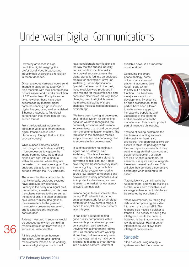
have considerable ramifications in the way that the subsea industry carries out its inspection tasks. "In a typical subsea camera, the digital signal is fed into an analogue module for conversion", says Jan Wulfsberg, Senior Applications Specialist at Imenco". In the past, these modules were produced in their millions for the surveillance and consumer electronics industry. Since changing over to digital, however, the market availability of these analogue modules has been steadily diminishing”.
"We have been looking at developing an all-digital system for some time, because we have recognised the potentially enormous performance improvements than could be accrued from the communication medium. The reduction in the analogue module supply, however, has encouraged us to accelerate this development”.
"It is often said that an analogue signal has no latency", said Wulfsberg. "This is not entirely true – time is lost when a signal is converted or digitized, but it does have very low baseline latency rates. If we are going to approach this with a digital system, we need to source low-latency components and develop low-latency processes. Just as important as hardware, we need to search the market for low latency software technologies."
Imenco began to be involved in this during 2012, when it first carried out a concept study for an all-digital platform for a new camera range. It hopes to complete the new platform later this year.
"It has been a struggle to find good quality components with a reasonable price, size and power consumption", said Wulfsberg. "Anyone with a smartphone knows that if all the functions are working at one time, it draws a lot of power. In many ways, what we have done is similar to placing a smart device into a subsea camera. Control of
Underwater Digital Communications
available power is an important consideration".
Continuing the smart phone analogy, some of the most successful platforms accommodate Apps - code written to carry out a specific function. This has been a major success in its development. By ensuring an open architecture, third parties have been allowed to write software apps to increase the popularity and usefulness of the platform, and at no extra cost to the manufacturer. This is an important part of Imenco's philosophy.
"Instead of selling customers the hardware and writing software individually for them", said Wulfsberg, "the openness allows our clients to tailor the package to suit their own specific demands. If they want to integrate their own contrast, colour enhancement, or video analysis function algorithms, for example, it is quite easy to integrate these into the main software. This will give their services a competitive advantage when bidding to the client”.
"Alternatively we can still write the Apps for them, and will be making a number of our own available, such as image enhancement, which can be selected by our clients”.
"Most systems work by taking the data and compressing the video into a format such as MP4. This reduced size makes it quicker to transmit. The beauty of having the intelligence inside the camera, however, is that that’s where the raw data resides. Having better information to use allows more intelligent compression.
"One problem using analogue systems was that there were no
Standards

UT2 February March 2014
37
real standards. Standards give the assurance that if something is developed, it can be used on all pieces of equipment. There are three levels of instrumentation interfaces, as defined by the Subsea Instrumentation Interface Standardisation (SIIS).
1 Analogue: Normal sensor 4-20 mA2 Digital Serial: CANBusNeither of these can accommodate video3 TCP/ IP over Ethernet
Imenco is making all its systems to run with the Ethernet option.
"We produced an Ethernet IP MP4 camera two years ago, getting the printed circuit board modules from Taiwan", said Wulfsberg. "We bought 20 of these units, but when we returned to the supplier, they had changed the shape of the board, which essentially meant redesigning the camera".
“Realising the insecurity of supply, the designers recognised that if they we wanted to continue with the development, they had to design the hardware as well as write the software”.
"To ensure the same consistent layout, we had to take control", said
Wulfsberg, "by doing this, we could start to achieve the sort of latencies we wanted. We essentially designed our own computer and also wrote the software for it. This not only assisted in further improving latency issues, but represented the final step in the journey of how we saw the future of the Smart Camera platform".
"Being responsible for the design of the software and the hardware allows unprecedented control, letting us potentially do things presently unachievable in the subsea arena. Perhaps the most prescient is that subsea devices can be made to automatically communicate with each other".
"Take a light, for example", said Wulfsberg. "If a camera receives too much light, it normally closes a diaphragm that prevents excess levels from reaching its CCD. Unfortunately, there may be unwanted side effects from this smaller aperture, which can result in changes in the fidelity of the image”.
"A more elegant technique, and much simpler in operation, would be for the camera to simply tell the light to reduce its intensity and instead delivering the optimum level to meet the camera's specifications”.
An immediately useful advantage of a software-driven system is in image recognition. Once a piece of software recognises an image, it can lock onto it. If this image moves, the software
can instruct the pan and tilt motor to automatically follow the target without the operator having to be aware.
A software-driven display system also has its own advantages. A typical screen in an ROV control room includes various pieces of information permanently burned into the image. These may include the depth of the ROV, possibly directional information, and numerous time readings. It is common to have the logo of the company carrying out the operation.
The display will incorporate numerous switches and dials.
"One very useful option that digital systems allow", said Wulfsberg", is to incorporate metadata. This is a continual stream of information recorded as part of the image-gathering process. The operator may elect to have them on screen, but using menu-driven controls, they can just be recorded in the background. It is even possible to write notes or attach files to the image".
One of the most potentially useful properties of a camera run over TCP/IP is that it may be able to communicate wirelessly. This makes it compatible with the idea of a subsea internet in general, and specific applications in particular in which stand-alone cameras are being increasingly envisaged.
Smart camera
The circuit board will fit inside an enclosure which will in turn fit into the standard 19in racks in the control room. This is connected to the monitor array

38
UT2 February March 2014
Fig 1 Soil resistance
Subsea cables have remained the principal conduit for transmitting information from one point to another, underwater, ever since the first was laid in 1850. Evolutionary technological advances over the years have permitted enormous amounts of information to be sent down a wire or optical fibre at very high speeds.
But what if wires or fibre cables are not present?
On land, this communications gap has been filled so successfully by wireless systems such as radio and high bandwidth acoustics, that in many cases, these have gone on to present a competitive alternative to fixed lines. Underwater wireless communications systems, however, have been relatively slow to develop, principally due to the lack of demand. But could this situation change?
Military and commercial autonomous vehicles are becoming a considerably more common feature of the subsea survey industry while oceanographic sensing in remote areas has become
established as a useful tool in achieving a greater understanding of the global environment. Wireless systems also now allow communications under the ice. The military has various confidential applications for remote underwater communications systems.
So what are the alternatives to fixed lines?
AcousticsThe most mature of the wireless underwater communications alternatives involves transmitting data by means of acoustic waves. This is the underlying mechanism by which Sonar works and as such, the principle is relatively well understood.
Acoustic transmission is essentially based on pressure waves caused by the physical movement of water molecules themselves.
High frequency sound is attenuated much faster than low frequency sound. Acoustic transmission, therefore, is a trade-off between distance (low frequency sounds can
travel further) and communication speed (high frequency signals have a high data transfer rate).
The resulting signal is characterised by long transmission ranges but a low bandwidth limitation.
In the deep ocean, acoustic transmission can be assisted by the Sound Fixing and Ranging (SOFAR) channel, sometimes also called the deep sound channel. It can be effectively considered as a pipeline for low-frequency sound. This anomaly in the water column is caused by temperature, water pressure and salinity profiles.
At the surface, where waters are warmer, the speed of the underwater sound wave increases. For different reasons, an increase in speed also occurs in greater depths where pressures are higher.
In between these two layers of increasing sound velocity lies the SOFAR layer, typically located around 2km from the water surface.
Alternatives to cables? This was the very question asked last year by the US Defense Advanced Research Projects Agency (DARPA).
In a forward-looking exercise, the US Navy had speculated on the sort of operations that it might likely be called on to do in the future, and what it would required to carry out these functions. In its turn, the support agency DARPA began to examine practical ways of supporting this.
Because of cost and complexity issues, the US Navy recognised that would still be called upon to operate globally but it would have to carry out its responsibilities using fewer weapons systems and platforms.
Unmanned systems and sensors
might be called upon as suitable candidates to provide support. Far from being a weapons-only programme, this solution could provide a range of non-lethal but useful capabilities such as monitoring, disruption, deception, networking, rescue, etc
Buy how to get these systems to the correct location? This would require the very legacy ships and aircraft that it was looking to replace.
One avenue of thought was to place unmanned systems on the deep-ocean floor in special containers. These would stay in position for an arbitrary length of time, possibly measured in years.
Almost half of the world’s oceans
are more than four kilometres deep. Distributing a network of small hidden nodes would provide considerable opportunity for inexpensive stealth. It would have to have a small footprint to prevent it from being detected and work without cables, but could represent a very useful tool.
The correct electronic trigger could remotely wake the deep-sea node. Small pods containing unmanned aerial vehicles (UAVs) could then be released and sent to the surface to be launched in order to provide aerial situational awareness, networking or decoy functions.
DARPA coined the term 'Falling Upwards' to describe this concept. The UFP (Upward Falling Payload) concept has three key subsystems:
DARPA
Underwater Communications

UT2 February March 2014
39
This channel can be best explained by having an upper and lower boundary layer. Within this, any sound travelling upwards will bounce off the ceiling and refract back down. When it hits the floor of this waveguide, however, the sound is diverted back upwards again. In this way, the sound can pass along the layer with minimal spreading loss of signal.
This makes it is possible to communicate extremely long distances. Whales naturally employ it while submarines will enter the channel specifically in order to contact receivers located hundreds or thousands of kilometres away.
Conversely, placing hydrophones in the SOFAR channel make it possible to detect radiated acoustic energy with such sensitivity, that when it was first discovered, it was even possible to distinguish the number of propellers in early submarines.
Acoustic waves can not only bounce off isopycnal surfaces such as a salinity gradients, but also or more solid objects such as fish or the hull
of a ship , these can result in multiple reflections. Robust protocols have been developed to negate these anomalies.
Electromagnetic An alternative wireless technique is electromagnetic transmission. In this context, the term 'electromagnetic' is normally synonymous with radio waves.
While acoustic waves are longitudinal, electromagnetic waves are transverse. More relevant is that electromagnetic waves are a self sustaining oscillation that do not require a medium to propagate.
The waves can reflect multiple times (which is objects can be seen in a lighted room). Underwater, in the absence of reflecting surfaces and boundaries that plague acoustics they tend to more point-to-point propagation.
Water is particularly efficient at absorbing electromagnetic radiation, which leaves the technique at an inherent disadvantage when compared with acoustic systems over long distances. Electromagnetic waves, however, are more useful for transmitting over short distances.
l The ‘payload’ itself which executes waterborne or airborne applications after being deployed to the surface
l The pressure tolerant encapsulation and launching system
l The UFP communications system that could be triggered from signal sent from anywhere on the planet
DARPA's role in the project would not be to develop these systems per sae, but to actively engage with various technical communities with the necessary experience in deep-ocean engineering such as the telecom and oil-exploration industries, as well as scientific groups and academia.
Underwater Communications
One such example, is that microwave and radio frequencies are unaffected by bubbles; the waves simply pass through them. Indeed, bubbles can theoretically improve communication as propagating through a vacuum affords lower signal loss.
This property can be exploited, for example, when towing seismic transponders, as these generate large amounts of bubbles. It may be possible to use these to communicate the short distances back to the vessel.
l The DARPA exercise invited engineers to contemplate less obvious communication mechanisms.
Among those suggested were chemical plume events possibly being triggered to release information to robots. Elsewhere, vibrations transmitted through the bedrock might be detected by remote seismic modems. Another novel idea was based on Neutrinos generated by a collider. Passing directly through the earth, they would reach the water boundary on the seabed.
The collision with the water could be recognised by a special Muon detector, which in turn would trigger a given operation.
The Applied Acoustics transceiver transmits and receives acoustic signals from a beacon attached to an object located in the water below.
An EMGS electromagneitc receiver

40
UT2 February March 2014
A basic optical system consists of an optical transmitter. This sends a signal through the water gap, where it is received by a photon detector at the other. Transmission is carried out using light emitting diodes (LEDs) or lasers.
Driven by the domestic electronics market, the latest devices have been engineered to be so efficient in converting an electrical signal into an optical signal, they have extremely low energy consumption rates.
This energy efficiency has been another contributing factor to companies re-evaluating the medium. Considerable volumes of information can be sent with the expenditure of relatively small amounts of energy. The derived unit of energy consumption is measured in joules-per-bit capacity.
The distance between the transmitter and the receiver is described as its point-to-point range. All things being equal, the distance a transmitted
signal can be detected is largely is limited by how much power is available LED transmitters.
If the water gap is turbid, this may affect the range. While electromagnetic systems may be improved by bubbles, optical communications can become disrupted.Other factors necessary to achieve long distances are the selection of LED colour and focussing as well as the sensitivity and dimension/speed trade-offs of photon detectors.
Blue light is the wave length of choice for clear water, although this is not the case for all conditions. Absorption changes with turbidity and areas with high chlorophyll levels such as the Baltic, Green light is more efficient.
Similarly, the more focused the beam the farther light can propagate but the more precisely the optical sensor must be positioned.
When the systems first started to be developed, this may have been an
Less common than acoustic or electromagnetic technologies, are optical systems. This communications technology is still in its infancy, but it has the potential to provide a significant impact in the subsea sector for certain applications. The reason is that light-based systems enjoy very useful properties unavailable to competitive communications methods.
The principal limitation of underwater optical systems is that they only allow communication at relatively short distances. This may be more than offset, however, by the fact that it is possible to provide ultra high data transfer rates of megabit signals at speeds equivalent to broadband. Lower bandwidth optical signals can go even farther.
One factor concerning communications is latency, or the speed that the signal propagates. (This is not the same thing as the data transfer, but simply concerns the physical speed of the wave).
Acoustic waves travel at around 1500m/sec in water (as opposed to 340m/sec it travels in air). Optical waves travel at nearer 300 000km/sec. Dividing this figure by the index of refraction of seawater gives the speed of light underwater.
Optical communication is still very much in its infancy. Ambalux successfully produced the first commercial blue light underwater modem only a decade or so ago and apart from specialised teams at academic bodies, there has been very little market pressure to invest in this research.
At present, the technology is at the stage where competing workers in the field are keen on collaborating to promote common interests. Nevertheless, many larger commercial companies have started to take a second look at the technology.
Optical Communications
A Sensorbot

UT2 February March 2014
41
Sensorbot
issue, but there are a generation of AUVs that can hover and hold position. Given multiple LEDs and using tens of Watts it might be possible to generate signal over distances theoretically in the region of 100m.
Cody Youngbull, Assistant Research Professor at the School Of Earth and Space Exploration, Arizona State University has been active in underwater optical communications research for many years. He has pursued a strategy which tries to mitigate the main drawback by artificially increasing the distance over which optical systems can operate.
"Instead of emitting an LED light beam in a straight-line connection, we have developed a small self-contained neutrally buoyant device called a Sensorbot that emits and receives light omnidirectionally.
"Taking advantage of low power electronics like LEDs, photodiodes and microcontrollers, the Sensorbot can incorporate its own power supply and operate in a truly wireless, ad-hoc situation."
The omnidirectional light it sends out is considerably less intense than the more direct focussed system, but this stands a greater probability of reaching another Sensorbot somewhere in the area as long as it is in range. Using a swarm ofSensorbots, information can effectively 'hop' from one device to another.
Last year, MacArtney teamed up with Youngbull to prove the potential of the system, when it carried out open demonstrations in test tanks at the Ocean Business conference in Southampton. MacArtney first became involved in the project when it was contracted to build the blessednode or masternode.
This was the name of the cabled optical modem at the start of the chain, responsible for sending the initial information out so that the Sensorbots could relay it onwards. Equally important, the masternode is used for picking up signals and data gathered by the Sensorbots and for relaying the information to topside software.
Left: Potential applications for Sensorbots. From Top: Assisting with diver communications; monitoring hydrothermal events; Autonomous vehicle communications under the ice; Pipeline monitoring

42
UT2 February March 2014
"The design of the Sensorbots has changed considerably over the last 12 months," said Youngbull. "We had originally intended to make the sensors that would be incorporated into the Sensorbot, and had started on the oxygen, temperature, pH, CO2, conductivity and pressure devices.
"It soon became clear to us, however, that not only were we competing with other companies unnecessarily, but we were preventing the end user from using their own preferred systems. The sensorbots now have an interface port to use external devices, leaving the Sensorbot solely as a modem"
Another issue was that the early system was based on photomultiplier tubes.
"This arrangement had a good track record in low light of the ocean, " said Youngbull, " but the tubes became saturated in brighter lights where sensorbots could find themselves working. This prompted a switch to photodiodes – even on the so-called 'blessed' node or masternode.
"One of the largest changes to the project was that we started a company called UON technologies (Underwater Optical Network). Amongst other things like organising patents, it made us concentrate more on practical uses. One useful application we recognised, was for distributed detection of chemicals in the water.
"Many conventional chemical sensors detect the conditions at a single point. Detecting information over a large number of points, however, would produce a far more comprehensive three-dimensional description.
"One interesting application is turbidity sensing during dredging operations," said Youngbull.
Dredging is a US$18bn a year Industry worldwide. With sea levels rising and ports needing to keep open, it is necessary to constantly dredge. This dredging process, however, results in toxins, heavy metals and other materials that were on the river floor, being suddenly suspended in the water and moved along the water course.
Sometimes, further along the river, operations such as fish farming or industries may require a certain level of fresh water may exist.
Using turbidity sensors distributed over the width of the river could not only provide a realistic indication of the sediment flow, but warn the authorities of impending problems if the dredging is not temporarily halted.
Elsewhere, distributed radiation detecting around locations such as Fukashima, could provide indications to the severity of any leakage. Other distributed sensing applications with network spatial resolutions commensurate with short range optical communications include rip-current monitoring, black-smoker plume detection, and pipeline monitoring.
A more classic point-to point wireless communication method has been developed by Lumasys a joint venture company between Sonardyne and Woods Hole Oceanographic Institution. In 2012, the company launched

UT2 February March 2014
43
Connecting with an underwater vehicle by acoustic (Left) and Optical (right).
the optical communication system, BlueComm.
Since then, the company has been conducting trials to see how BlueComm performs in the field, including controlling a hybrid ROV/ AUV called Nereus.
"The BlueComm high speed optical data uplink allows for the extraction of large amounts of data in an energy efficient manner," said Darryl
Newborough, Director of Subsea Instruments at Sonardyne, "and supports the transmission of camera imagery and high definition video in real time.
"As water depths increase, conventional remotely operated vehicles (ROVs), as well as their associated tether, launch and recovery systems, need to be larger and heavier. This in turn requires larger and more expensive vessels.
"The BlueComm system, however, may one day eliminate the need for such tether cables altogether by offering a new degree of freedom in underwater robotics, with data being wirelessly transmitted at rates of up to 20 megabits per second."
Early work to discover and solve the practical issues that may be encountered when combining optical systems with underwater vehicles, were recently conducted off the island of Guam in the Western Pacific. Onboard the research vessel MV Alucia, was the Nereus hybrid vehicle.
The Nereus has two operational modes. Depending on its mission, it can either swim autonomously, or be transformed into a conventional ROV by connecting up a micro-thin fibre optic tether.
This tether allows the transmission of high quality, real time imagery from the vehicle to the surface, however, it is fragile and needs to be replaced after each deployment.
The reason for the trials was to examine the suitability of the optical Using sensorbots to monitor turbidity while dredging
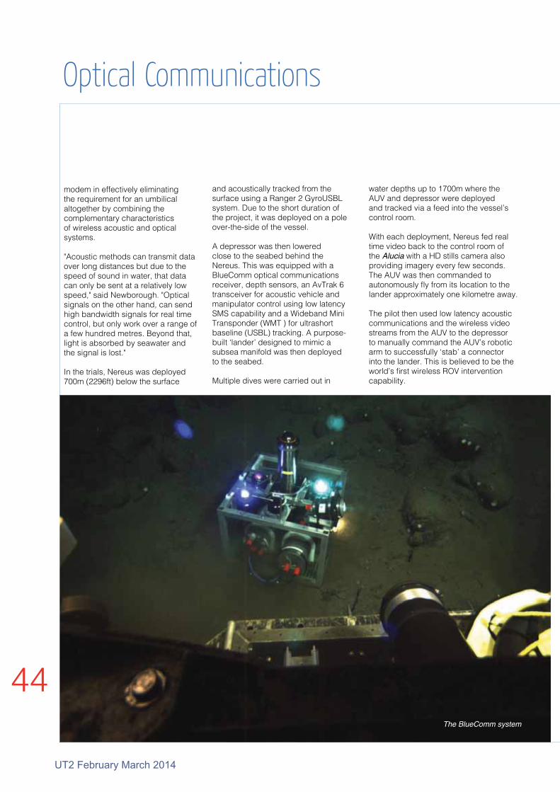
44
UT2 February March 2014
modem in effectively eliminating the requirement for an umbilical altogether by combining the complementary characteristics of wireless acoustic and optical systems.
"Acoustic methods can transmit data over long distances but due to the speed of sound in water, that data can only be sent at a relatively low speed," said Newborough. "Optical signals on the other hand, can send high bandwidth signals for real time control, but only work over a range of a few hundred metres. Beyond that, light is absorbed by seawater and the signal is lost."
In the trials, Nereus was deployed 700m (2296ft) below the surface
and acoustically tracked from the surface using a Ranger 2 GyroUSBL system. Due to the short duration of the project, it was deployed on a pole over-the-side of the vessel.
A depressor was then lowered close to the seabed behind the Nereus. This was equipped with a BlueComm optical communications receiver, depth sensors, an AvTrak 6 transceiver for acoustic vehicle and manipulator control using low latency SMS capability and a Wideband Mini Transponder (WMT ) for ultrashort baseline (USBL) tracking. A purpose-built ‘lander’ designed to mimic a subsea manifold was then deployed to the seabed.
Multiple dives were carried out in
Optical Communications
BlueComm Optical modem on the seabed
water depths up to 1700m where the AUV and depressor were deployed and tracked via a feed into the vessel’s control room.
With each deployment, Nereus fed real time video back to the control room of the Alucia with a HD stills camera also providing imagery every few seconds. The AUV was then commanded to autonomously fly from its location to the lander approximately one kilometre away.
The pilot then used low latency acoustic communications and the wireless video streams from the AUV to the depressor to manually command the AUV’s robotic arm to successfully ‘stab’ a connector into the lander. This is believed to be the world’s first wireless ROV intervention capability.
The BlueComm system

UT2 February March 2014
45
AmbaluxOne company involved closely in high-bandwidth, underwater 'Free-Space Optical (FSO) 'communications systems is Ambalux.
Its standard product is the 1013C1 Ethernet-compatible, optical transceiver capable of supporting 10Mbps data communications.
A single 1013C1 transmitter/receiver pair can provide 10Mbps simplex operation through a water-column range of up to 40m, depending on water clarity and ambient sunlight, while a second transmitter/receiver pair permits full-duplex operation over the same range. It uses standard 10BaseT Ethernet interfaces and fully supports TCP/IP and UDP protocols.
"During set-up, the transceiver automatically handles acquisition and link integrity, behaving like just another Ethernet cable, except it is wireless and fiberless," said a spokesman.
"The 1013C1 incorporates sophisticated automatic gain-control to provide trouble-free performance under a wide variety of environmental conditions."
The transceiver system consists of a transmitter and a receiver each packaged in its own anodized-aluminum pressure vessel. The transmitter and receiver are connected via wet-mateable connectors to an electrical harness that carries data and power.
Standard harness configurations use Subconn Circular 12-pin connectors in a “Y” configuration between the 2 pressure vessels and the system interface. Other harnessing configurations and connectors are available on request,
including fibre-optic interface.
Because the 1013C1 is fully Ethernet compatible, the only additional system components are the computer or other data source, and a power supply (24VDC standard, other voltages on request).
The transceiver pressure vessels are mounted using a saddle machined to the same radius (2.005in plus tolerance) or with a resilient rubber cushion to compensate for dimensional errors and prevent hard spots.
Similar Rugged Design as the Multi SeaCam®
Flat and Dome Port Options Available
Full HD 1080p/30 Video Output
Fiber Optic and Hybrid Coax Connector Options
Titanium Housing & Sapphire Port
FIBER OPTIC OUTPUT
NEW
HD Multi SeaCam®
www.deepsea.com 1-800-487-3775
Ambalux transducer

46
UT2 February March 2014
Historically, the majority of communication systems have been based on wire or fibre optic cables. In recent decades, there has been a revolution in terrestrial communication methods, with the internet embracing both wired and wireless technologies.Researchers around the world working on discrete underwater communications initiatives could be effectively fabricating the building blocks of a deep-sea Internet.
The network-based approach could lead to improvements in tsunami detection, offshore oil and natural gas exploration, surveillance, pollution monitoring and other activities.
One group actively carrying out research in this area are a team at the University at Buffalo led by Tommaso Melodia, associate professor of electrical engineering.
The Signals, Communications and Networking Research Group in the university's Department of Electrical Engineering in the School of Engineering and Applied Sciences are carrying out research in wireless communications and networking, cognitive radios, extreme environment (i.e, underwater, underground) communications, secure communications, data hiding, information theory and coding, adaptive signal processing, compressed sensing, multimedia systems, magnetic resonance imaging and radar systems. “A submerged wireless network will give us an unprecedented ability to collect and analyse data from our oceans in real time," said Melodia.“Making this information available to anyone with a smartphone or computer, especially when a tsunami or other type of disaster occurs, could help save lives.”
Land-based wireless networks rely on radio waves that transmit data via satellites and antennae. Unfortunately, radio waves work poorly underwater. This is why sound wave-based
techniques are more commonly used to communicate underwater.
In tsunami prediction, for example, data is sent from tsunami sensors on the sea floor to surface buoys by acoustic waves. The buoys convert the acoustic waves into radio waves to send the data to a satellite, which then redirects the radio waves back to land-based computers.
"Many systems worldwide employ this paradigm," said Melodia, "but sharing data between them is difficult because each system often has a different infrastructure."
The framework Melodia is developing would solve that problem. It would transmit data from existing and planned underwater sensor networks to laptops, smartphones and other wireless devices in real time.
Melodia tested the system recently in Lake Erie, a few miles south of downtown Buffalo.
In one experiment, Hovannes Kulhandjian and Zahed Hossain, who are both doctoral candidates in his lab, placed two, 40lb sensors into the water. Kulhandjian then typed a command into a laptop. Seconds later, a series of high-pitched chirps ricocheted off a nearby concrete wall, an indication that the test worked.
"A deep-sea internet has many applications, including linking together
buoy networks. In these situations, it could deliver a more reliable tsunami warning, thereby increasing the odds that coastal residents can evacuate," Melodia said.
"It may also help collect oceanographic data and monitor pollution. The framework will encourage collaboration among researchers and potentially, eliminate the duplicative deployments of sensors and other equipment," he said.
There are also military and law enforcement applications. For example, drug smugglers have recently deployed makeshift submarines to clandestinely ferry narcotics long distances underwater. An improved, more robust underwater sensor network could help recognise these vessels.
"The framework could also be useful to the energy industry, which typically relies on seismic waves to search for underwater oil and natural gas. Industry’s efforts could be aided by network of interconnected devices working together," he said.
"We could even use it to monitor fish and marine mammals, and find out how to best protect them from shipping traffic and other dangers," Melodia said. "An Internet underwater has so many possibilities."
Subsea Internet
Hovannes Kulhandjian and Zahed Hossain working in Lake Erie
Seafloor sensors in pressure housings transmit information to surfaces buoys. Can they link to smartphones and other wireless devices in real time?

UT2 February March 2014
47
Subsea InternetNEW Cygnus DIVE Mk2Underwater Thickness Gauge
+44 (0)1305 265533 • sales@cygnus- instruments.com • www.cygnus- instruments.com
l
metal thickness gauge
l Large brighter AMOLED
display for clear viewing
l Measures through
coatings in multiple
echo mode
l On-board data logging
capability
l Topside monitoring with
measurements video overlayed
l Twin crystal probe option for heavy
corrosion and anchor chains
Wrist mountable underwater
NEW
RS Aqua, UK distributors for Nova Scotia-based MetOcean Data Systems, has signed a multi-year contract involving the supply of MetOcean Self-Locating Datum Marker Buoys (iSLDMB) to the Royal Australian Navy (RAN). The first generation SLDMB devices were developed by MetOcean some two decades ago and the latest versions are enormously popular with Search and Rescue (SAR) organisations, Ocean Research Institutes, Environmental Agencies, Navies and Oil & Gas companies around the world.
The iSLDMB accurately follows near surface currents and can be rapidly air/vessel deployed for Search & Rescue operations or to track spills etc. This latest version, which conforms to NATO specifications, is equipped with bi-directional Iridium satellite telemetry which, when coupled with back-office data presentation services such as those offered by JouBeh Technologies (also Nova Scotia), provide the user with
real-time data location and tracking information, essential for SAR and spill tracking operations. Recently, RS Aqua also won a contract form the Centre for Environment Fisheries and Aquaculture Science (CEFAS), Lowestoft, to supply an extensively equipped model SV3 Wave Glider manufactured by Liquid Robotics.
This contract follows hard on the heels of a similar award from the National Oceanography Centre, Southampton.
The Wave Glider is an innovative product; a mobile platform powered totally via renewable solar and wave energy resources. It offers oceanographic and meteorological data acquisition capabilities in coastal waters through to deep ocean via remote piloting services.
Some 200+ model SV2 Wave Gliders are now active in global waters and the SV3 version, released this Autumn, benefits from an increase in scale thereby offering greater solar power capacity and larger payload capabilities. A by-product of those
features is the availability of an auxiliary thruster, for times of critical need. The SV3 Wave Glider comprises a surface float connected to a submerged propulsion system via a high-bandwidth, 4m streamlined umbilical. On the surface float there are three solar panel arrays that provide power to the on-board electronics and forward and aft payload compartments.
The submerged propulsion module captures wave energy to propel the Wave Glider through the water and can also accommodate an additional subsea payload module.
These payload compartments accommodate Modular Power Units or Modular Payload Units of different sizes that can be utilised for a variety of sensors and power requirements.
Drifter Marker Buoy and Wave Glider
Wave Glider
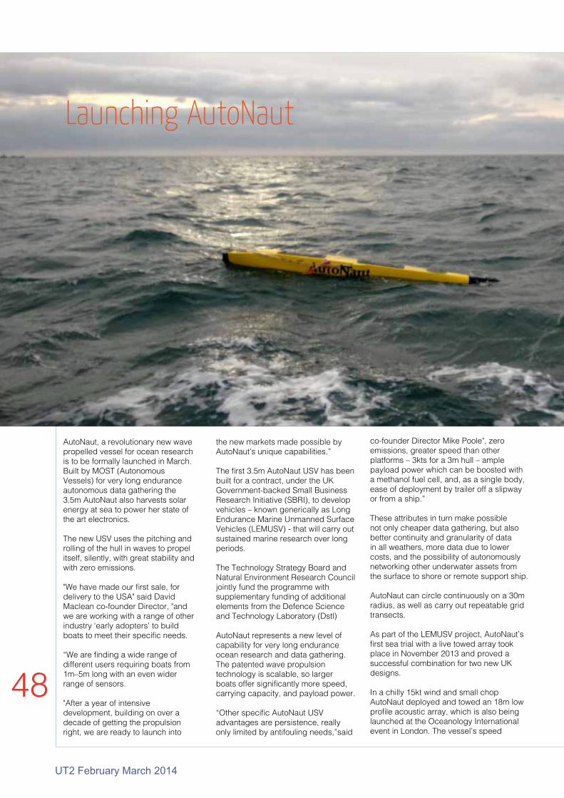
48
UT2 February March 2014
AutoNaut, a revolutionary new wave propelled vessel for ocean research is to be formally launched in March. Built by MOST (Autonomous Vessels) for very long endurance autonomous data gathering the 3.5m AutoNaut also harvests solar energy at sea to power her state of the art electronics.
The new USV uses the pitching and rolling of the hull in waves to propel itself, silently, with great stability and with zero emissions.
"We have made our first sale, for delivery to the USA" said David Maclean co-founder Director, "and we are working with a range of other industry ‘early adopters’ to build boats to meet their specific needs.
“We are finding a wide range of different users requiring boats from 1m–5m long with an even wider range of sensors.
"After a year of intensive development, building on over a decade of getting the propulsion right, we are ready to launch into
the new markets made possible by AutoNaut’s unique capabilities.”
The first 3.5m AutoNaut USV has been built for a contract, under the UK Government-backed Small Business Research Initiative (SBRI), to develop vehicles – known generically as Long Endurance Marine Unmanned Surface Vehicles (LEMUSV) - that will carry out sustained marine research over long periods.
The Technology Strategy Board and Natural Environment Research Council jointly fund the programme with supplementary funding of additional elements from the Defence Science and Technology Laboratory (Dstl)
AutoNaut represents a new level of capability for very long endurance ocean research and data gathering. The patented wave propulsion technology is scalable, so larger boats offer significantly more speed, carrying capacity, and payload power.
“Other specific AutoNaut USV advantages are persistence, really only limited by antifouling needs,”said
co-founder Director Mike Poole", zero emissions, greater speed than other platforms – 3kts for a 3m hull – ample payload power which can be boosted with a methanol fuel cell, and, as a single body, ease of deployment by trailer off a slipway or from a ship.”
These attributes in turn make possible not only cheaper data gathering, but also better continuity and granularity of data in all weathers, more data due to lower costs, and the possibility of autonomously networking other underwater assets from the surface to shore or remote support ship.
AutoNaut can circle continuously on a 30m radius, as well as carry out repeatable grid transects.
As part of the LEMUSV project, AutoNaut’s first sea trial with a live towed array took place in November 2013 and proved a successful combination for two new UK designs.
In a chilly 15kt wind and small chop AutoNaut deployed and towed an 18m low profile acoustic array, which is also being launched at the Oceanology International event in London. The vessel’s speed
Launching AutoNaut

UT2 February March 2014
49
of around two knots was not noticeably changed and her steering remained good, with a series of circles being completed without difficulty.
“We expected this success as a result of dummy towing trials with our earlier prototype, both at sea and in a wave tank,” said Poole. “It was great to see a real array in action with the new boat.”
The new miniaturised low profile array is provided by J+S Ltd, a UK engineering company with bases in Barnstaple and Aberdeen. Ease of handling and the robust nature of the array were clearly demonstrated.
The array was able to track a target of opportunity and, with the absence of tow vessel noise, 360deg acoustic coverage was achieved.
Andy Toms, Managing Director for J+S said “This successful trial is the result of months of intensive sonar engineering work by our Product Development Team. The collaboration with MOST (AV) demonstrates the potential of LPA technology as a lightweight, easily deployed, acoustic sensing system”
AutoNaut towing an 18m low profile array which can be seen as a pipe on the starboard side, disappearing over the stern.
ScanFish Katria
A new intelligent wide-sweep ROTV system has been designed by EIVA to optimise magnetometer surveys while giving reduced operation costs and high data quality.
Called the ScanFish Katria, this has been especially designed for the detection of sub-bottom magnetic anomalies. The intelligent platform allows for time-efficient magnetometer surveys, as it covers larger survey areas in one sweep through a horizontal setup of four magnetometers.
By means of the terrain-following operation mode, the magnetometers are positioned as close to the seabed as the topography allows. This ensures
EIVA launches ROTV solution dedicated to Magnetometer surveys
less expensive operations and high-quality data with better indication of signal strength and origin.
The magnetometer type employed within the ScanFish Katria is the Geometrics G-882 Marine Magnetometer, a high-end yet low-cost solution and the most used in the industry.
As the ScanFish Katria is towed at a distance, any type of vessel can be used without risking the survey data being affected by its magnetic signature.
The ScanFish Katria standard package combined with the optional extras such as a turn-key solution.
SeeByte has successfully integrated SeeTrack Neptune with the OceanServer Iver2 Autonomous Underwater Vehicle (AUV) for the use of Defence Research and Development Canada (DRDC).
The SeeTrack Neptune software provided DRDC with a platform to design its own autonomous routines for the Iver2 vehicle and to perform collaborative multi-vehicle operations with other Allied nations.
SeeTrack Neptune is an adaptive planning tool for optimising the execution of AUV operations. It supports high-level goal-based mission descriptions and allows the matching of mission requirements against vehicle(s) capabilities.
SeeTrack Neptune

50
UT2 February March 2014
Gemini NBI
Tritech is pleased to announce the sale of 4 Gemini NBI systems to Subsea Technology and Rentals (STR), Great Yarmouth.
This is a significant purchase for STR, who recently rebranded to reinforce their position as the provider for high-technology subsea equipment.
STR already offers a comprehensive suite of Tritech industry-standard sensors and sonars for rental including sonars, profilers and bathymetric systems.
This latest purchase will enhance their pool of subsea equipment, to support excavating and dredging companies’ requests for high-specification multibeam sonars.
The Gemini NBI offers a narrow vertical beam at 130° swath for applications where precision in target detection and monitoring of a position is required. The Gemini
NBI offers the same high refresh rate currently offered by the Gemini range of sonars.
The purchase was driven by customer demand and STR’s commitment to providing high-quality, new and innovative rental products to the buoyant subsea market.
Neil Jackson, Sales and Operations Manager at Subsea Technology and Rentals (STR) commented: “This purchase not only allows us to continue providing the latest technology to our customers, but it also complements our existing rental business, which is ever increasing.”
Suite of Gemini NBI Sonars Added to STR Rental Pool
Scott McLay, Sales Director, Tritech commented: “The purchase of these Gemini NBI units by STR highlights Tritech’s ability to provide products which provide operators, working in the most challenging environments, with a solution where reliability and performance are paramount.
"STR’s continued investment in Tritech products not only fulfils a market requirement, but also reinforces their commitment to supplying high-quality subsea equipment.”
The Marine Operations team at Lundin Tunisia, operator of the Oudna field 80km offshore Tunisia in approximately 300m of water, recently contacted buoyancy specialist Seaflex. The Oudna was serviced until recently by the FPSO Ikdam.
At end of the field’s viable lifecycle, the problem arose of how best to decommission the FPSO – and in particular how to take care of the delicate operation of disconnecting several hundred tons’ worth of moorings without incident.
It was determined that a combination of 41 different-sized parachute-style Air Lift Bags (ALBs) up to 50t in size needed to be installed on the moorings to reduce their tension to something manageable.
The deck-mounted linear winch was rated to 450t, but because the three mooring anchors were extremely well embedded in the sandy seabed, the effective tension on the chafe chain would have increased by an estimated 1.5 to 2 times the original 400t.
The use of the Seaflex ALBs allowed the deck-mounted
linear winch to pull on the chafe chain so as to slacken the connection to the Ikdam deck hook. The connecting shaft was then pulled out from the wren hook and by doing so this freed the chafe chain so allowing the mooring system to ever-so-gently be lowered on a wire, thereby de-tensioning the system.
Once released, the chafe chain was transferred to a nearby AHTV which held the de-tensioned mooring system whilst the Ikdam FPSO disconnected.
Seaflex Air lift Bags
Lift bags on the FPSO Ikdam
Equipment

UT2 February March 2014
51
OptoLinkFibre optic connectors
Expanded beam lensesUnlimited number
of matings
Available worldwide
Standard depth rating 6,000 metres
Denmark Norway United Kingdom USA FranceNetherlands Germany Bahrain Australia Singapore
Worldwide solutions

52
UT2 February March 2014
Doing More With Less
Across the globe, subsea vehicle operators and authorities are finding themselves in a similar position where they are required to do more with less. Despite shrinking research budgets, demands have often increased.
Concerns from climate change to ocean acidification campaigners have become louder. Civilian ocean agencies have to increasingly guard against tsunamis and hurricanes, often with declining resources.
In the wake of Macondo, the offshore industry is facing increased regulation, especially in sectors such as ultra-deepwater and Arctic regions. This needs to be monitored continuously. Elsewhere, the defence community still has to fulfil traditional roles while engaging in a range of new demands from anti-piracy to harbour security.
Most of these demands involve the use of vessels of some sort. One area that may offer a comparative increased return on investment is to employ unmanned maritime vehicles (UMVs) in the place of manned units.
"The major classes of UMV are remotely operated vehicles (ROVs), autonomous underwater vehicles (AUVs) and unmanned surface vessels (USVs)," said Justin ManleySenior Director, Business Develop-ment at Teledyne Benthos. "These vehicles are typically used to carry out survey, inspection, observation and connectivity operations.
Survey"While the growth in the large/deep UUV survey market seems to have slowed, new underlying technologies such as synthetic aperture sonar (SAS) continue to reduce costs and consequently, bring the technology within reach of operators with smaller budgets," said Manley.
"In the late 1990s, small USVs first began to demonstrate the ability to collect high quality survey data
without the demand for sizeable support vessels.
"Today, using affordable small platforms, often vessels of opportunity, survey operators can now conduct seafloor surveys at depths up to 1000m and count upon data quality equal to the larger more expensive systems.
"Modular architectures allow diverse payloads and rapid battery changes. Now one UUV can conduct multiple missions and maximise operating time, and consequently the return on investment."
InspectionSmall ROVs have matured rapidly to significantly change mission economics. Available in many sizes, shapes and price ranges, these ROVs enable rapid and effective inspections of the seafloor and structures.
Although depth ratings are not typically equal to work class ROVs, the demands often lie within reach of smaller systems which in turn, are benefiting from new technology and improved economics.
New sensors are now available to support applications such as leak detection and pipeline imaging. Improved auto-pilots and subsea positioning reduce the burden on operators.
"The significant increase in the number of micro-ROVs deployed by police departments, universities and other fiscally constrained operators is a testament to the economics of this class of UMV," said Manley. "While the user base is growing, the gap between the capabilities of work class ROVs and the micro-ROVs is closing. Select low-logistics ROVs now offer the high thrust-to-weight ratio required to support long tethers in high currents."
Flexible architectures increasingly allow these ROVs to be adapted to powerful sensors without the high drag
the “bolt-on” approach imposes on micro ROVs. Thus a low-logistics ROV can now support missions such as bridge piling inspections in extremely low visibility and high current environments.
"A task, previously slow and expensive or even impossible, is now routine and economical," continued Manley. "Likewise inspection of ship hulls

UT2 February March 2014
53for security, ship husbandry or law enforcement is enabled by the new generation of capable but low logistics ROVs."ObservationOcean observation has traditionally relied on vessel-based measurements and moorings, which require significant logistic investment. In comparison, extended endurance UMVs and autonomous profiling floats
observation is the US Navy Littoral Battlespace Sensing – Glider (LBS-G) programme. This envisages acquiring and deploying 150 gliders to support Navy operational observations. While the low capital and operational costs of these tools is a clear benefit to the economics of ocean observation, there is another, subtle, effect to note.
"Academic or government programmes often share data collected by these platforms freely and often online. With hundreds of gliders and thousands of floats deployed there is a wide user base to advance new concepts and technologies. Together, the sharing of data and wide user community make ocean observing UMVs highly leveraged investments."
ConnectivityWhile wireless networks and satellite navigation have revolutionised life ashore, acoustic systems bring similar benefits to undersea operations.
"Empowered by advances in digital signal processing, tones and pings have given way to broadband schemes," said Manley. "These systems offer reliable connections between many platforms and in some cases, also provide positioning
information.
"Adaptive networks have been demonstrated, but have not been widely deployed. Technologies are mostly closed, with operators dependent on single sources or forced to own potentially redundant equipment. Subsea connectivity is having an impact, but it still evolving and penetrating the market."
"It is clear that UMVs are reshaping the economics of marine operations," said Manley, but most operators are accruing only incremental benefits and not the full potential of the technologies available."
The potential of UMVs can be thought as being analogous to mobile phones.
"The current situation for UMVs is much like the personal electronics scene of the late 1990s," said Manley. "A well outfitted early adopter would have a standalone GPS receiver, mobile phone and personal digital assistant. A lucky few that managed to connect that phone to the PDA had access to a rudimentary world wide web, in grayscale and text."
A Networked System of Undersea Vehicles
offer broad area coverage, both spatial and temporal, at low cost.
Using buoyancy, thermal or wave energy power sources, these new UMVs can remain at sea for months and years rather than hours and days. They have demonstrated endurance to cover large distances or patrol in place for extended periods.
"Traditionally, physical oceanography has been the focus of these platforms, due to available sensors and limited payload energy budgets," said Manley "Today, new biogeochemical sensors are being demonstrated on long endurance platforms.
"Perhaps the most significant demonstration of the economic impact of UMVs on ocean

54
UT2 February March 2014
"Similarly, current UMV users must acquire specific kit for particular missions. Modular architectures and shrinking sensors are increasing utility for individual platforms. "We are still awaiting the equivalent of the smartphone era in ocean operations."
NETWORKED UMVSContinuing the mobile phone analogy, what might UMV operators look forward to in the future?
"Today average smart phone users can take their device anywhere in the world," said Manley," and access voice calls, email, web browsing, map based navigation and a host of specialised “apps” for advanced tasks.
"This capability is built upon enabling developments in hardware, especially compact processors and power sources, as well as accepted standards for connectivity. Such a reality is coming to the undersea realm.""In coming years, UMVs will draw upon acoustic, radio and optical connectivity to “network” into ever more productive roles. UMV payload modules will be swappable between a traditional survey UUV and a long endurance glider."
Gliders could incorporate propellers to overcome the occasional current or better navigate in operational areas such as under ice. Elsewhere, drifting and energy harvesting surface platforms will provide overhead coverage for acoustic telemetry and positioning to heterogeneous undersea systems.
So how might such a future change the picture for actual ocean applications? "Consider the scenarios," proposed Manley." Survey A typical UUV is deployed from a chartered fishing vessel to locate and follow a pipeline. Undersea “cell towers” guide the UUV and ensure
operators ashore receive prompt notification of the UUV’s findings.
This means that the condition of the pipeline can be analysed and anomalies flagged for subsequent follow-up, without using a dedicated vessel, thus significantly reducing the cost.
InspectionA small, smart ROV is deployed from a similarly small commercial support vessel. Sophisticated autopilots link the ROV and vessel, and the pair slowly follow the pipeline to inspect the previously-discovered anomalies.
A trained watch stander “points and clicks” the operation to completion, releasing highly skilled ROV pilots for intervention tasks (optimising capital and operating investments).
On large fixed installations, an Autonomous Inspection Vehicle (AIV), deployed from a dedicated launch recovery and docking basket, provides wireless inspections of wellhead equipment.
ObservationIn open water, a drifting profiling float with advanced instruments detects a potential oil leak and adapts its dive to surface and alert operators ashore.
A patrolling glider and nearby surface vessel (both of them powered by naturally-harvested energy and thus on station for months or years) can home-in and sample the oil plume, sharing the data with both commercial and Government observers.
The regulators determine the event is a natural seep and response vessels are not required (saving both organisations valuable funds and time).
ConnectivityIntegrated networks of various wireless technologies provide low bandwidth but reliable coverage much like first generation cellular networks.
A Gavia Offshore Survey AUV

UT2 February March 2014
55
Full data sets may reside on local UMV solid state drives but status information and key data identified through onboard analytics can be exchanged across the network, ensuring operators are informed and support assets are deployed for maximum efficiency.
"The pipeline survey UUV is now docked with a gateway node along the pipeline," said Manley. "To request recovery, the UUV sends the equivalent of a text message to request the intervention of a series of predetermined regional assets, such as fishing vessels.
"The nearest available vessel would confirm the request on the network, and move to recover the UUV. A recovery fee would more than compensate for the short deviation from fishing activity."
Such an integrated subsea network minimises downtime, even without the speed that is taken for granted in wired networks.
"UMV technology is continually evolving," said Manley. "As the land and air unmanned vehicle communities have discovered, however, the regulatory environment does not always empower technology."
Early policy analysis of AUVs, for example, looked at impacts on marine life, but notably did not consider the right of freedom of navigation. In 2005, the US Navy inspired an effort to develop technical standards for UMVs. A series of initial standards were focused on technical issues.
During this timeframe technologists evaluated the potential for “smart” UMVs to interact with other vessels at sea. Generally these efforts concluded that it would be feasible for UMVs to “share the road” and follow the “rules of the road” at sea.
Since these initial technical and policy steps there has been a gradual increase in interest in the policy regime.
"The complete lack of official regulation on UMV operations will not continue," predicted Manley. "Presuming that regulations, or even best practices, are forthcoming, it is in the interests of all sides to develop a rational policy framework. Maximum benefit from UMVs will most likely be obtained if future policies do not treat all UMVs alike.
"It should present requirements appropriate to UMV size and available energy, lest major economic benefits be lost.
"Any regulatory framework should recognise the limitations of subsea connectivity (low bandwidth but reliable) and place appropriate demands on the network as a key risk mitigator," concluded Manley.

56
UT2 February March 2014
Vehicles
Forum Energy Technologies has received an order from DOF Subsea to supply seven Perry XLX 200HP work-class remote operated vehicle (ROV) systems, including five Dynacon Launch and Recovery systems (LARs).
The ROV systems will be delivered during the first and second quarters of 2014.
DOF Order

UT2 February March 2014
57
MacArtney has delivered a powerful and versatile Sperre SUB-fighter 7500 ROV system for DBB ROV Services, a major Danish ROV contractor.
It will be used for offshore drill support, inspection, survey and support jobs in connection with installation of offshore wind turbines. The new ROV is the fourth Sperre SUB-fighter system in operation for DBB ROV Services.
Along with DBB Salvage and DBB
MacArtney ROVJack-Up, DBB ROV Services is part of the DBB Group.
This type of ROV has gained a reputation as an extremely robust and easy to maintain ROV, designed and built for the harsh North Sea environment.
The Sub-fighter ROV can also be delivered as a crawler with caterpillar tracks for tasks where most of the work takes place on the seabed – for instance with jetting systems and cable trackers.
SeeByte has successfully integrated SeeTrack Neptune with the OceanServer Iver2 Autonomous Underwater Vehicle (AUV) for the use of Defence Research and Development Canada (DRDC).
The SeeTrack Neptune software provided DRDC with a platform to design its own autonomous routines for the Iver2 vehicle and
to perform collaborative multi-vehicle operations with other Allied nations.
SeeTrack Neptune is an adaptive planning tool for optimising the execution of AUV operations. It supports high-level goal-based mission descriptions and allows the matching of mission requirements against vehicle(s) capabilities.
SeeTrack Neptune
Sub-fighter ROV

58
UT2 February March 2014
Forum Energy Technologies has received an order from Subsea 7 to supply eight work-class remotely operated vehicle (ROV) systems. The ROVs will be delivered through late 2014 and 2015.
The order comprises two Perry XLX Evo ROVs for Subsea 7’s new-build Heavy Construction Vessel and six Perry XLX-C ROVs for three new-build Pipe-lay Support Vessels for the Brazilian market.
The Perry XLX Evo heavy work-class and XLX-C medium work-class ROVs are the latest generation of the Perry XL series. The XLX-C features enhanced performance across the full range of intervention and survey activities without compromising the reliability of the XL series.
Forum is pleased with its association with Subsea 7, a premier subsea contractor,” said Bill Boyle, Forum Subsea Technologies’ Senior Vice President.
“The choice of Perry vehicles for the operationally demanding Brazilian market represents a vote of confidence in the reliability of the XLX-C system and supports Forum Subsea’s strategy of providing first class engineering, and after-market support and service to Subsea 7 and our other Brazilian customers from our facilities in Rio de Janeiro and Rio das Ostras.”
Vehicles
Forum Energy Technologies Awarded Contract for Eight Remotely Operated Vehicles from Subsea 7
Applied Acoustics’ new revolutionary sparker system will be shown at Oceanology 2014 stand this year.
The system combines high quality data capture and improved resolution with hard-wearing sparker tips that minimise operational downtime.
Designed for high and ultra-high resolution geophysical surveys, and for use with single and multi-channel acquisition systems, the system is capable of providing high quality data with vertical resolution up to 25cm, in water depths from 5 to 1000 metres.
Power for the Dura-Spark is
Applied Acoustics Dura-Spark Debutprovided by the new CSP-N seismic energy source with its reverse polarity high voltage charger and unique proprietary thyristor switching, features that result in maximum electrode durability and long-life.
Sparker system
Perry XLX-C Remotely Operated Vehicle
Perry XLX Evo

UT2 February March 2014
59
Applied Acoustics Dura-Spark Debut
Forum
Thresher Shark 76mm ø1080p6000msw3x Zoom
Horn Shark40mm ø1080p800msw
Bull Shark100mm ø1080p3000msw12x Zoom
Meet the ImencoHD Family
AVIATION | DIVING | ENGINEERING & DEVELOPMENT | LIF TING & HANDLING | SUBSEA | WORKSHOP
Come and see us at Oceanology International, Stand K501, 11-13 March 2014, London, Excel. For further information call us on +44 (0)1224 701749 or email [email protected] quoting OI14UT2.
Imenco is an EPC contractor to the maritime sector providing mechanical and electronic equipment along
with bespoke engineering solutions to major oil, subsea and drilling companies worldwide.
imenco.com
For a demonstration, call +44 (0)1224 701749
IME-14-0004-SOS-ad-210x297c.indd 1 31/01/14 11:41

60
UT2 February March 2014
With 11 thrusters, high payload and a number of advanced features, the new Leopard is claimed by its manufacturers, Saab Seaeye, to be the most powerful ROV of its size in the world.
The Leopard is aimed at the compact work-class market, where it can handle more tooling, cameras and survey equipment than any other ROV in its class. It can be used in a wide range of work tasks including drill support, pipeline survey, salvage and deep water IRM.
The Leopard weighs 27t for the full system, compared with over 70 tonnes for other workclass ROVs. These can be loaded onto smaller vessels
The minimal deck footprint of the Seaeye range is maintained with the combination of a 20 by 8ft single lift, A-Frame winch launch and recovery system (LARS) and a 20ft control cabin for easy transport and rapid mobilisation.
Its pack of eight horizontal thrusters and three vertical thrusters gives the Leopard exceptional thrust, powering the vehicle forward at over 4kts, and enabling it to hold steady in strong cross-currents.
For the pilot, the vehicle's iCON intelligent control system gives clear and enhanced information whilst independently managing each device on the vehicle, including auto redundancy that will keep the ROV working even with multiple equipment damage.
The pilot will also find that iCON delivers better handling characteristics – including pitch and roll stabilisation for the best quality survey data and to allow stable flight even with large tools and sensors deployed.
Taking a Leap Forward"The Leopard has been designed with the pilot in mind," said a spokesman, "while other inventive features make life easy for the operator in the field.
"For instance, the networked design of the iCON control system has refined the main electronics pod into an intelligent power distribution and data hub, and re-located the brains of the system into sensors and actuators around the vehicle. This provides greater information for the user and makes maintenance far simpler and quicker.
This innovation also avoids the need to partially dismantle the ROV to reach its electronic heart. It also offers building-block simplicity for equipment changes along with remote internet access for upgrades and support.
The chassis has been designed with rapid reconfiguration and easy maintenance in mind. A large open payload bay within the vehicle allows for ample tooling and survey sensors to be installed rapidly on sliding trays. Its one tonne through-frame-lift capability and four point docking system for tooling skids allows more demanding payloads to be added.
First to order the Leopard has been Australian-based Dive Works Subsea Solutions.
It is the fourth ROV they have bought from Saab Seaeye in the last ten years.
"We've found that even though we are a Commercial Diving and ROV services company, the industry is heading more and more towards using ROV's rather than divers," said Managing Director, Andrew Ford.
ROV frame
11 SM9 thrusters (3 vertical, and 8 horizontalthrusters
Umbilical
Electronics pods
Vehicles
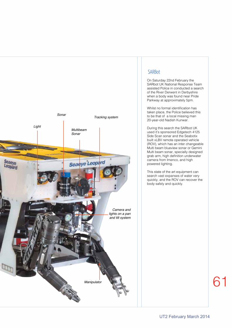
UT2 February March 2014
61
Camera and lights on a pan and tilt system
Light
SonarTracking system
Manipulator
MultibeamSonar
On Saturday 22nd February the SARbot UK National Response Team assisted Police in conducted a search of the River Derwent in Derbyshire when a body was found near Pride Parkway at approximately 5pm.
Whilst no formal identification has taken place, the Police believed this to be that of a local missing man 20-year-old Nadish Kunwar.
During this search the SARbot UK used it’s sponsored Edgetech 4125 Side Scan sonar and the Seabotix built vLBV remote operated vehicle (ROV), which has an inter changeable Multi beam blueview sonar or Gemini Multi beam sonar, specially designed grab arm, high definition underwater camera from Imenco, and high powered lighting.
This state of the art equipment can search vast expanses of water very quickly, and the ROV can recover the body safely and quickly.
SARBot

62
UT2 February March 2014
The development of renewable projects based on Wave and Tidal power generation is progressing in many countries around the world. Some of these are nearing the stage where the installation of the first arrays can be considered a possibility.
But is sufficient effort being concentrated on how to get the power generated ashore?
"In order to make the arrays commercial, it is important that the individual generators can be installed and retrieved for maintenance or repair with the minimum of effort," said Dave Pye, Renewable Energy Business Development Manager at SEA CON.
"This has two main implications on the design of the generator and its base structure or mooring. It needs a design that can utilise smaller vessels for installation and recovery. It also requires a reliable method of connecting and disconnecting the electrical and fibre optic cabling. This latter issue is particularly important."
In the formative days of the Marine Renewables industry, some people, often in key positions, adhere to the belief that there are many connectors available that are presently used in the Oil and Gas sector, that can be used for renewable designs.
"This claim is about as incorrect as it is possible to be," said Dave Pye. "There are two main reasons for this."
(a) The Oil and Gas sector industry is a fully developed and mature industry, able to afford the high costs of the most advanced connectors and cable termination devices. Marine Renewables, however, cannot stand these costs
(b) The environment in which the connectors have to survive is far more benign than that to be found in Marine Renewables. The only real problem is water depth, which can be overcome by the use of pressure compensation.
"The costs of the connectors are mainly driven by such factors as the high specification materials used, the need for protection when un-mated in the subsea environment, the level of testing and qualification required and the comparatively low quantities that are ordered at any one time. An order of more than 10 of the same item being comparatively rare."
The working environment for the connectors has probably the greatest effect on the design and cost of any product to be used in Marine Renewables. The relatively shallow water has numerous consequences: (a) Temperatures can be far higher than in deep water and this promotes both marine growth and corrosion. Corrosion can be resisted by the use of materials such as Titanium or Super Duplex stainless steel but this comes at a cost.
Marine growth is more difficult to combat without the use of environmentally unfriendly materials so is by far the most difficult to mitigate. Both corrosion and marine growth MUST be controlled in this environment by material selection or other methods.
(b) With both wave and tidal converters, there is a constant refreshing of the oxygen content in the water, something not present to such an extent in deep water. Again, this encourages corrosion and marine growth.
(c) In relatively shallow waters, there is continuous pressure cycling due to wave and tide variations. This will have some effect on the sealing of the connectors.
(d) The power generated by the devices is also not constant. Wave power produces a power level constantly varying. Tidal power, however, goes from zero to maximum twice per day. This may or may not have a serious effect on the connectors, but it must still be considered as a potential issue.
"Overall, this industry sector requires products that will work as well (and as long) in a far harsher environment as those used in the Oil and Gas sector but at a far lower cost, possibly something like 50% less," said Dave Pye.
"To achieve this, the connector industry requires both quantity
and most importantly, standardisation."
Electrical And Fibre Optic Connections
Renewables
Remains of bronze locked ring
Marine growth on Hydralight

UT2 February March 2014
63
At present, quantities are, by necessity, very low due to most of the requirements being for prototypes. In these applications. It is possible to use connectors with lower grade materials as the deployment times are much shorter.
"Serious marine growth and corrosion, however, can be evident even after periods of weeks," said Dave Pye. "Considering the first array installations, quantities will still only be quite small so it will be difficult to reduce costs significantly.
"The factor that will serve to bring the greatest reduction in cost will be standardisation. This does not mean putting constraints on how the connectors function or are designed, but by reducing the number of variations in things such as current, voltage, numbers of contacts, cable types, test requirements etc."
The Oil and Gas industry has introduced a number of specifications which have allowed connectors to be procured from a number of manufacturers with confidence that they will perform to specification.
These industry-standard specifications have been developed both by the major users of the products and the oil companies themselves but there have also been Joint Industry Projects (JIP) with the same objective.
"For the connector industry to be able to produce what is needed for Marine
Renewables, it is desirable that
something similar is set
up – a JIP involving connector
manufacturers, generator developers and
installation contractor would be very welcome."
Left: Hydralight wet mate optic connector
The Carbon Trust's Offshore Wind Accelerator programme (OWA) has awarded £6 million to DONG Energy co-fund the full scale demonstration of a new offshore wind turbine foundation called the Suction Bucket Jacket.
This jacket designed was based on ideas from the SPT Offshore foundation, a finalist in a global competition run by the Carbon Trust to find lower cost foundation solutions. If the demonstration is successful, it could be implemented in future commercial projects from 2017 – including the UK Round 3 projects.
The Suction Bucket Jacket combines conventional jacket technology, consisting of welded tubular space frames, with suction buckets for anchoring the foundation firmly to the seabed. The bucket foundation (suction caisson) is a well-known concept from the oil and gas industry, where it has been used for more than 30 years for oil platforms installed in the North Sea.
The prototype foundation will be installed with a state of the art measurement system that will provide essential data for the verification of the Suction Bucket Jacket concept.
Suction Bucket Jacket
Suction Bucket Jacket

64
UT2 February March 2014
Sonar

UT2 February March 2014
65
Teledyne BlueView has released a novel geo-mosaicking tool, ProMapperto be used for search and recovery, harbor inspection and waterway mapping from a surface vessel A remotely operated vehicle can be used to map deeper water for site clearance surveys, pipeline inspections and seabed inspections around structures.
When conducting a survey ProMapper uses BlueView’s 2D forward looking sonar image, allowing the seabed’s image directly in front of the vehicle plot the sonar image on a nautical chart in real time.ProMapper’s intuitive operation allows the user to see the imaged area from the map while ensuring that any ‘gaps’ in the image are known and can be filled.
"The tool is perfect for fire departments, sheriffs department ports and harbours, or imaging any canal or waterway," said Jon Robertson, Field Operations Manager at Teledyne BlueView.
"We have just launched the latest 2D control software, ProViewer4 This has a completely new graphical user interface (GUI). We have expanded the imagery and have incorporated more user-friendly controls. ProViewer4 gives us a lot more control over the sonar as well. Some advanced controls include control of the source signal amplitude, more gain and threshold control and enhanced zoom feature.
"If we set a maximum range of 100m with the 900kHz, for example, we want to be able to get the maximum power into the water to improve the imaging further away. If the rangeis reduced, however, we want less power and lower amplitude because we don't want to wash out the image. This gives better resolution."
"The frequency of 2D sonar used depends on the image resolution required. A common option is a 900 kHz sonar which provides a 130deg horizontal field of view," said Jon Robertson. "Alternatively, in some applications, the user may select a dual frequency (900 kHz and a 2.25MHz) sonar which can give both long range navigation and closer range high resolution in one unit. If the project requires longer range coverage a 450kHz can provide data up to 300m."
The system essentially consists of two parts. First a 2D forward looking imaging sonar is normally mounted on a pole off the side of a vessel, although it can equally be mounted on a remotely
operated vehicle with GPS and Heading. Second ProMapper is connected to the 2D sonar control software, ProViewer 4.
"The positioning accuracy on an ROV is not as good as positioning on a surface vessel, but underwater vehicles have other inherent advantages," said Jon Robertson.
The sonar data, along with global positioning system (GPS) and heading information is fed into Teledyne Blueview's ProViewer, 2D forward looking sonar control software.
ProViewer displays the sonar data to produce high-resolution video-like imagery.
This imagery data is transmitted from ProViewer control software into ProMapper. This starts building a map of the area based on the GPS locationand heading.
It can then be exported as a GeoTiff file (A 2D geo-referenced image) or other formats, where it is superimposed on top of a Google aerial image or if
available, a digital nautical chart.
"If you see the target you are looking for in ProMapper, GPS coordinates can be displayed by clicking on the target," said Jon Robertson.
The Big Picture

66
UT2 February March 2014
Imenco TrialsOne of the world’s largest manufacturers of ROVs recently ran a series of independent trials comparing subsea cameras from seven different manufacturers to establish what would be the best cameras to fit to their future fleet of ROVs.
Of the seven manufacturers whose products were tested against a variety of criteria, Imenco’s subsea Bull Shark HD-SDi camera, and Hammerhead Shark SD Colour Zoom camera came out top of the scorecard result tables.
Stuart McConnell, General Manager of Imenco said; “This is a great result for Imenco. We have consistently promoted the quality of our camera range to the market since opening the UK office in 2010.
An independent test by such a world leading organisation, proving our products to be overall ‘top of class’, can only help our future sales activities and get us into the forefront of specifiers and buyers minds”.
Mr McConnell went on to say “The Company have also created a specific adapter so that the Tiger Shark Digital Stills camera can be used on all their ROVs”.
Tests covered colour accuracy, perceived sharpness of the camera image, image distortion, and signal to noise ratio.
Imenco’s Shark Range includes HD-SDi, Low-Light, Wide Angle, Digital Stills and Zoom cameras rated from 500msw –6000msw dependent on the chosen housing and the job the camera is required to do for the customer.
The Bull Shark HD-SDi camera
The scientific team at the GEOMAR Helmholtz Centre for Ocean Research Kiel recently completed a scientific cruise to study the relationship between hydrothermalism and volcanism in the Mid-Atlantic Ridge (MAR).
Using a specially designed REMUS 6000 type AUV built by Hydroid, the team collected bathymetric data on thousands of kilometres of the seafloor, much of it previously unexplored.
The GEOMAR team’s REMUS AUV, named ABYSS, was instrumental to the mission’s success. A modular vehicle, ABYSS was equipped with a suite of sensors that allowed it to autonomously identify and survey areas of volcanic activity along its preprogrammed flight routes.
The vehicle’s data collection instruments included an Edgetech 2200-MP 120/410 kHz sidescan sonar, a Seabird SBE 49 FastCat CTD and a SeaBat Reson 7125 multibeam echo sounder.
Additionally, the AUV was equipped with an onboard turbidity sensor to help it locate areas of undersea geothermal activity, including the hydrothermal vents and black smokers that typically occur in volcanically active seafloor regions.
For its standard load out, ABYSS uses a Kearfott T-24 inertial navigation system (INS) and a Teledyne RDI 300 kHz acoustic Doppler current profiler/Doppler velocity log (ACDP/DVL) as its primary navigation systems.
It was also equipped with a Paroscientific 8B7000 pressure sensor and an Imagenex 852 forward-looking echo-sounder, which provided reliable depth readings and helped avoid unexpected obstacles, respectively.
Hydroid AUV surveys Mid-Atlantic RidgeLike all REMUS 6000 AUVs, ABYSS has a maximum operating depth of 6000m. The vehicle’s typical mission duration of 16hrs and maximum speed of 5kts allowed GEOMAR scientists to cover approximately 100km per dive.
Equipped with dual lithium-ion batteries, ABYSS can achieve a maximum mission time of 22hrs. In the event that the vehicle’s battery power reaches a critically low level, the AUV immediately surfaces and sends SMS messages with its location to the crew via satellite.
ABYSS significantly increased the value of the data collected by the GEOMAR scientific team. “One of the key benefits of AUV-mounted instruments is their ability to use higher frequency sound waves for sonar data collection,” said Prof Colin Devey, Scientific Head of the AUV Team at GEOMAR.
“Unlike surface ship bathymetry, the low flight altitude of our REMUS 6000 allowed us to use high-frequency sonar that, when used from the surface, is only viable for littoral imaging.
"This short wavelength sonar allows us to produce significantly higher resolution images.”
Equipment
Franklin Volcano Summit

UT2 February March 2014
67
DeepSea Power & Light has developed the HD Multi-SeaCam camera, its first high definition video camera.
Derived from the Multi-SeaCam camera, an industry workhorse, this general purpose camera has been widely used for over 16 years in offshore oil, oceanographic, academic, and military applications around the world.
This is the latest extension of the Multi-SeaCam legacy cameras with the availability of true full HD video capabilities.
The new HD Multi-SeaCam video camera builds on the same rugged
HD Multi-SeaCamdesign as the original, with a 6000m rated Titanium housing and scratch-resistant sapphire port, while providing SMPTE 292M compliant HD-SDI 1080p/30 video output in 106.4mm (4.19in) long, 48mm (1.9in) diameter housing.
New optics provide a low distortion 74° horizontal field of view with a 2-inch to infinity depth of field providing a full context view in vivid HD picture quality. Initially available with industry standard hybrid coax bulkhead options, the HD Multi SeaCam now offers fibre optic output
The enhancements to the widely
popular, compact, and nearly indestructible Multi-SeaCam camera not only brings high definition video to our customers, but allows for HD cameras to be brought to some of the harshest and most unforgiving
Since its first cruise in 2009 aboard the RV Meteor, GEOMAR has used ABYSS for almost a dozen expeditions around the world. Previous ABYSS expeditions
include searching for the remains of Air France flight 447 and locating valuable deposits of gold, zinc, copper and other minerals around seafloor hydrothermal vents.
In future expeditions, ABYSS will be used to survey areas of significant tectonic activity, with the hope of establishing some basic predictive measures for seafloor earthquakes.
On arrival we split into four groups for the Narec site tour. The tour encompassed four different facilities at the site: the 15MW Drive Train Test Facility, the 3MW Tidal Turbine Drive Train Test Facility, the Charles Parsons Test Centre, and the 100m Wind Turbine Blade Testing Facility.
Also briefly introduced were the wave flume, simulated seabed and still water tank. At each facility a short description of the equipment was given along with the capabilities of the resources available and type of testing they are capable of.
NAREC Site Visit Wednesday 18th September 2013
By Steve Addison, AtkinsAfter the tour Andrew Mill was introduced by Andrew Pople (Atkins and Vice Chair of the North of England Branch).
Andrew Mill welcomed the audience and introduced the first speaker, Ignacio Marti, to talk about the role Narec plays within the industry, its capabilities and future plans on behalf of Narec. He opened with information about the site, including the fact that it is the largest open access test facility in the world.
This allows them to cater to all types of customer, and testing schedules, often
developing systems as part of joint industry efforts with both academic and commercial partners. Having been introduced to the onshore capabilities,
Ignacio described the development of an offshore demonstration wind turbine field allowing technologies designed and tested onshore to be verified offshore in an accessible location. The discussion following Ignacio’s presentation centred on what specific services Narec could provide.
The evening’s second speaker
North of England
HD Multi-SeaCam

68
UT2 February March 2014
SUT
The first evening meeting of 2014 for the North East region focused on the collaboration between the fishing industry and subsea technology. As the interest to develop offshore technology increases, it is vital to work in harmony to sustain the available resources.
Mike Montgomerie, Gear Technologist from Seafish demonstrated a wealth of knowledge having been a trawler man himself. Mike gave an overview of the various fishing methods and explained which posed greater risks of interaction with subsea structures; pelagic trawl, beam trawls, seine nets, demeral trawl and scallop dredges were some of the fishing methods mentioned.
To help the collaboration between fishermen and other offshore industries the Kingfisher information service provide trawler men with an accurate map of the location of structures on the seabed by collating information from various offshore technology sectors.
In addition, the “Fish safe unit” alerts fishing vessels when approaching subsea structures, this system is kept up to date with six monthly updates.
Mutual respect was evident between fishing and the Oil and
Gas industries. Seaweed and fish congregate near structures causing fishermen to focus their haul around these areas rather than avoiding them. Videos of nets and structures during laboratory testing demonstrated how susceptible lines are to snagging on the smallest discontinuity.
The industry is moving towards “closed” subsea structures to minimise the risk of trawl doors and net snagging. If a net does snag, the boat will reverse to try and free it; compensation is available if nets have to be cut. Should a net become tangled (most commonly on pipelines) there is a 24/7 helpline for trawler men and boats are tracked so un-reported damage could be traced.
The second talk of the evening was presented by Ian Davidson, Principal Engineer at Well Completions, FMC. The presentation began by summarising the need for protection of structures. Subsea structures comprise of pipelines, manifolds, umbilicals and pipeline end connectors. They require protection from fishing nets, trawl boards and dropped objects to keep fishing boats and crew safe, maintain production and ensure the impact on the environment is kept to a minimum.
To help with the development of subsea structures that will interact with fishing activity, industry standards have been developed to provide
Subsea Resources: North Sea Collaboration
was John Watson. John spoke about prototype development and the role Narec plays in ‘de-risking’ new technology. The reduction of risk is very important from both a technological and financial perspective.
Narec is able to contribute to the reduction of risk by offering companies the facility to carry out full scale controlled test, whether to simulate specific conditions that have been seen in operation, or to simulate predicted worst case scenarios or any other situation the client may want to test.
John then delivered slides on the behalf of Siemens MCT. These slides emphasised the need from
guidance on expected snag loading, model testing, min radius and optimum leg angles.
Ian described the requirement for a generic Fishing Friendly Structure (FFS) that would be simple in design with low operating costs. It was to integrate with a generic Christmas tree and be deployed through a 5m diameter moon pool. Accurate scale models were used to develop and test the design with flume tank tests and verify intended performance.
Design improvements focused on the overall body shape, the diameter of the legs and location of the gussets to reduce ground gear snagging. FMC developed the design over many years to create an elegant structure that un-folded once through the moon pool.
Collaboration with the fishing industry was evident; throughout the design process valuable input from fishermen was sort and a “note of approval” from the Scottish Fisherman’s Federation of the final design was gained.
Following the talks and answering questions from the floor, the audience and speakers enjoyed discussing the night’s topics over a buffet. Many thanks to the speakers, chairman and FMC Corporation for sponsoring the event.
both engineers and financial teams for proof of concept, whether this be verification of theoretical data in applied applications or proof of profitability.
The final speaker of the evening was Peter Allan of UTEC Geomarine. Peter’s presentation was focused around quantitative assessment of risk to cables laid on the seabed and using this to dictate burial depth.
He began by introducing the current method for assessing risk to laid cables (i.e. the Burial Protection Index, which was developed for the telecoms industry) and described why this was not suitable for power cables, namely that there is no redundancy in power cables.
Peter then went on to outline how a quantitative method could be used, taking into account shipping activity, anchorage locations and type (based on ship type) and soil type.
Using UTEC Geomarine’s method a quantitative risk level can be calculated. Based on this number an appropriate risk level can be decided, dictating the burial depth for the cable.
After the interesting questions and answers session Andrew Pople thanked the speakers and hosts, following which the audience and speakers retired to the buffet. Thanks are extended to the speakers, and to Narec for hosting the evening.
Wednesday 22nd January September 2014
North of England
There’s no Plaice Like the Dogger Bank’

UT2 February March 2014
69
BIRNS celebrated a major milestone at the recent Underwater Intervention show in New Orleans. 2014 marks the company’s 60th year in business, and BIRNS held a well attended event in its booth at the show to commemorate the anniversary.
The event included a slideshow of historical company photos honoring the founding CEO Jack Birns, a former LIFE Magazine photographer, and the company’s achievements to present day in a presentation by current CEO Eric Birns. The festivities included cocktails and a large 60th birthday cake, as well as drawings for a new touchscreen laptop and a pair of Beats headphones.
“I am humbled and grateful that BIRNS has had the honor of serving the industry for the last six decades,”
60th Anniversary
says Eric Birns, President and CEO.
“My father started this company as a small business in Hollywood selling photographic equipment to the Navy and other customers, and we have now become an ISO 9001:2008 and
NAVSEA PRO-020 certified global leader in high performance connec-tors and lighting solutions. All of us at BIRNS would like to thank the indus-try for the honor of serving its needs for the last 60 years, and look forward to our next 60 years together.”
The next issue of UT2 will feature Offshore TechnologySeabed ProcessingSubsea EquipmentPollution ControlPipelinesSubsea EquipmentOcean Mining
as well as the usual features. It will be distributed at the OTC event in Houston
UT2 February March 2014
1
UT2January February 2013
T H E M A G A Z I N E O F T H E S O C I E T Y F O R U N D E R W A T E R T E C H N O L O G Y
PipelinesUnderwater Vehicles
Deadline: 1st April

70
UT2 February March 2014
SEACON has set up a Business Development Management team comprises of Craig Smith, Sergio Mendez, John Blair and Tom Schwinn.
Craig Smith completed his business studies at college whilst working for SEA CON. With his new role of Business Development Manager Craig will continue to promote and develop the company within the Military, Oil & Gas and Oceanographic sectors.
Sergio Mendez is a graduate of Texas A & M University in College Station, Texas with a Bachelors degree in Marketing and International Business.
While Sergio has a primary focus on the coordination of business development activities for SEA CON Advanced Products, he is also a member of the Subsea Fiber
Optic Monitoring steering committee (SEAFOM). Part of their responsibility is to create and document the standards for future subsea architecture.
John Blair is from College Station, Texas and joined the US Army straight from high school. John has a strong background in the Seismic market as well as the Oil & Gas subsea market.
Tom Schwinn is a graduate of the University of Massachusetts, Dart-mouth with a Bachelor of Science degree in Electrical Engineering. He is an accomplished Engineer and Project Manager. Most recently Tom worked at General Dynamics Electric Boat designing and building nuclear sub-marines for the US Navy. Tom’s area of expertise at GDEB was sonar systems. He has an extensive knowledge of outboard cables and connectors.
Sergio Mendez
Craig Smith
Tom Schwinn
John Blair
UTEC, one of the world’s largest independent survey companies, has made significant expansion of the US team serving Gulf Coast clients.
The Houma-based Industrial Meas-urement/Dimensional Control group has benefited from the addition of 3D control surveyors, led by IMDC supervisor Greg Carlos.
He said “The group has been work-ing together for a number of years and having the ability to keep the team together by joining UTEC is a huge plus. It gives us the ability to continue to provide services to exist-ing clients on the Gulf Coast, and ac-cess to IMDC staff from other UTEC offices will be important in growing the service line within the region.”
UTEC VP of Measurement Technol-ogy, Mark Klusza, added: “With the addition of a full metrology and 3D scanning division in Houma, we now have one of the largest full service metrology services companies sup-plying services to the oil and gas industry in key locations around the world.”
Scour Prevention Systems Ltd ap-pointed Tim Smith as business development manager.
Tim was previously sales manager at leading offshore wind industry ser-vice provider CWind. Prior to that he was business development manager at Fendercare, where he played a leading role in developing the com-pany’s activities in the renewables sector, leading to the establishment of the James Fisher Renewables division.
Last year the company successfully completed offshore demonstrations of their innovative scour solution on E.ON’s Scroby Sands wind farm off the Norfolk coast. Scour Prevention Mats are now endorsed by E.ON and commercially available to the global offshore market.
SEACON UTEC
Scour Prevention Systems

UT2 February March 2014
71Register to attend for free at:
www.oceanologyinternational.com
Organised by: Learned Society Patron:
OceanOlOgy InternatIOnal 2014 wIll feature:
n �8�newly�developed�conference�programmes�covering�the�latest�developments�for�key�service�and�industry�sectors
n The�world’s�largest�exhibition�featuring�over�520�exhibitors,�10%�larger�than�the�previous�event
n A�product�demonstrations�programme�including�more�visiting�vessels,�on-water�and�waterside�demonstrations�than�ever�before
n Networking�opportunities�with�your�international�peers�across�every�related�sector
n Hydrographic Surveyn Geophysical Surveyn Geotechnical Surveyn Subsea Engineering Servicesn Oceanographic Measurementn Ocean Forecastingn Metrologyn Navigation and Positioningn GISn Marine Environmental Surveyn Marine Environmental Consultancyn Coastal Engineering Consultancy
OceanOlOgy InternatIOnal 2014 shOwcases sOlutIOns fOr:

72
UT2 February March 2014
BRING CLARITY TO THE WORLD BELOW
LEADING TECHNOLOGYKongsberg Maritime continues to be at the forefront of subsea technology. Through an extensive portfolio of cutting-edge survey and inspection systems, from multibeams to AUVs, we provide clarity to the world beneath the waves. Our solutions for hydrography, fisheries and underwater navigation and inspection enhance precision and efficiency, giving you the edge in operational performance. You can rely on our technology to deliver a clear view of the world below, because with Kongsberg Maritime, you always have THE FULL PICTURE.
km.kongsberg.com
Imag
e© S
andr
o Fe
nech