ustrial silencers - nap · ustrial silencers talogue, classified as listed below: rae medium degree...
TRANSCRIPT
u s t r i a l S i l e n c e r s
talogue, classified as listed below:
RAE medium degree straight through absorption
RIE or RIS multi-chamber reactive type silencersfor industrial area applications. RRE or RRS multi-chamber reactive type silencers with
higher performance for residential area applications. RR/AE or RR/AS multi-chamber silencers combining
maximum reactive performance and absorption design for critical high performance requirements. SASE multi-chamber spark arrester silencersfor :applications where spark control is required.
e particular model and size is defined by the model and inlet or outlet pipe nominal diametel: The above range
cates standard models but many other designs for special lications are available. Please enquire on the MRR, SAST, ranges and our numerous special designs.
C o n s t r u c t i o n All silencers are constructedfrom heavy gauge hot rolled cold quenched sheet steel with all welded construction. Internal components are stiffened and braced to minimise resonances and vibration inducedfatigue. Flanges are supplied to Table D or ANSI requirements. Threaded pipe
ends are to BSP or metric threads. Drain plugs arefitted as standardfor removal of condensate. All external surfaces are
finished with high quality silicone based heat resistant aluminium paint which provides lasting protection at temperatures up to 600°C.
O p t i o n a l e x t r a s Matchingflange kit, comprising twoflanges, gaskets and
two sets of nuts and bolts. (EK Kit.) H Support brackets for vertical or horizontal installation. Des igned to pressure vessel standards, AS1 21 0, BS5500
or ASMEVIII. F l a n g e d stainless steel expansion bellows. H Tail pipes, transition pipes, ducting andflues. Construct ion in special steels.
S u r f a c e treatment of blast clean, aluminium metal spray and epoxy sealer to BS2569 Part 2.
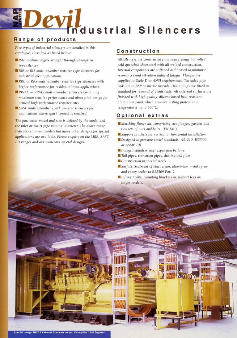
c Special design RRIAS Exhaust Silencers to suit Caterpillar 3516 Engines
S p e c i a l n o t e s To maximise performance in critical situations the pipe between the silencer and the machine may need to be
acoustically lagged to reduce breakout. Certain special designs such as for compressors require heavier construction,
internal bracing, dished ends and full welding although the nominated dimensions may be complied with. We always
recommend two stage silencing in super critical applications
(ie. >40dB IL) with isolation between each stage in order to
avoid flanking.
S i l e n c e r S e l e c t i o n Once the attenuation requirement has been established the selection of a suitable silencer can be made from the application chart on page 7.
The correct silencer should meet the following, often conflicting, requirements:
required attenuation phys i ca l size, including inlet and outlet flange size n minimum back-pressure n lowest cost
In selecting a silencer for a particular application it is
generally sufficient to match inlet sizes although on diesel engines the exhaust silencer inlet flange is usually 50mm
or more than the exhaust diameter. The back-pressure introduced by the installation of Devil Industrial silencers is negligible for absorption mufflers (RAE silencers) and only very rarely are problems encountered with reactive mufflers.
(Silencers RIE, RRE, RR/AE and SASE).
Certain problems may occur when two silencers are installed
in series. We do not recommend the use of two reactive silencers in series.
For clarification on the correct silencerfor difficult applications contact your local 'NAP Silentflo' representative.
Other requirements that may influence silencer selection and
design include:
n overall silencer length compared to the space available
available installation positions
h e a t radiation in closed spaces n mixed flow environments n cleaning and maintenance access n vibration
I n s t a l l a t i o n D e t a i l s In all cases the silencer, whether inlet or discharge, should be
mounted as close to the engine or machine as practical. Inlets and exhausts should be directed away from nearby noise sensitive areas to minimise directivity effects. Exhaust silencers on diesel engines should be followed by
a length of pipe equal to the silencer body length.
The distancefrom the exhaust manifold to the silencer
should be as short as practical. Devil Industrial silencers will not perform correctly i f installed back to front. Always install the silencer with the gas flow in the direction indicated by the arrow on the silencer case. Vibration generated noise is a significant problem with many industrial applications and care should be taken to avoid
rigid mounting of the silencer Solidly mounted silencers can
be fatigued by thermal expansion and continual vibration,
resulting in internal collapse and failure of external fittings. For optimum silencer life the silencer should be isolated from the source of vibration by aflexible coupling and hung or supported by vibration isolated spring mounts.
Note also that the internal construction and design of special
silencers particularly when used on compressors or blowers
may not follow standard designs exactly. In some cases such
items may even be designed as pressure vessels.
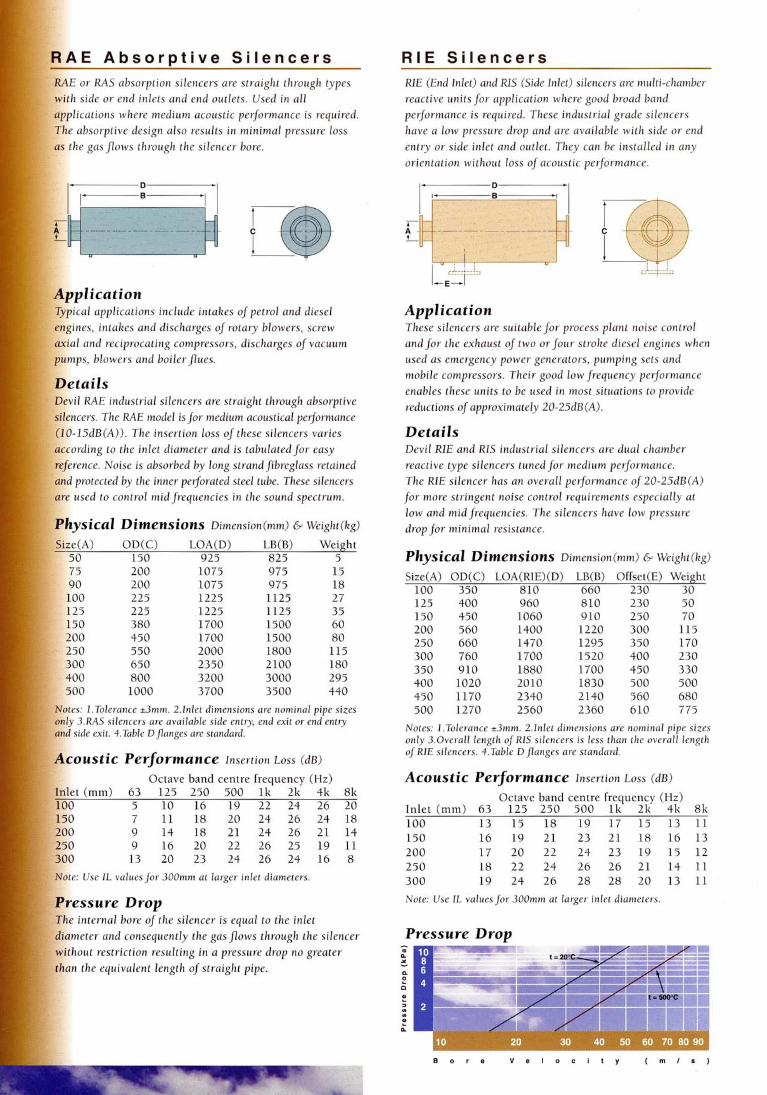
E or RAS absorption silencers are straight through types h side or end inlets and end outlets. Used in all lications where medium acoustic performance is required. absorptive design also results in minimal pressure loss
the gas flows through the silencer bore.
R I E S i l e n c e r s RIE (End Inlet) and RIS (Side Inlet) silencers are multi-chamber reactive unitsfor application where good broad band performance is required. These industrial grade silencers have a low pressure drop and are available with side or end entry or side inlet and outlet. They can be installed in any orientation without loss of acoustic performance.
~plication ical applications include intakes ofpetrol and diesel nes, intakes and discharges of rotary blowers, screw l and reciprocating compressors, discharges of vacuum
mps, blowers and boilerpues.
1 RAE industrial silencers are straight through absorptive cers. The RAE model is for medium acoustical performance ISdB(A)). The insertion loss of these silencers varies rding to the inlet diameter and is tabulatedfor easy
rence. Noise is absorbed by long strand fibreglass retained protected by the inner perforated steel tube. These silencers used to control mid frequencies in the sound spectrum.
lysical Dimensions Dimension(mm) G Weight(kg)
e(A) OD(C) LOA(D) LB(B) Weight 150 925 825 5 200 1075 975 15 200 1075 975 18 225 1225 1125 27 225 1225 1125 35 380 1700 1500 60 450 1700 1500 80 550 2000 1800 115 650 2350 2100 180 800 3200 3000 295 1000 3700 3500 440
.Tolerance *3mm. 2.Inlet dimensions are nominal pipe sizes J.~(AS silencers are available side entry, end exit or end entry
side exit. 4.Table Dflanges are standard.
7 11 18 20 24 26 24 18 9 14 18 21 24 26 21 14 9 16 20 22 26 25 19 11 13 20 23 24 26 24 16 8
internal bore of the silencer is equal to the inlet
hout restriction resulting in a pressure drop no greater n the equivalent length of straight pipe.
Application These silencers are suitable for process plant noise control andfor the exhaust of two orfour stroke diesel engines when used as emergency power generators, pumping sets and mobile compressors. Their good low frequency performance enables these units to be used in most situations to provide reductions of approximately 20-25dB (A).
Details Devil RIE and RIS industrial silencers are dual chamber reactive type silencers tuned for medium performance. The RIE silencer has an overall performance of 20-25dB(A) for more stringent noise control requirements especially at low and mid frequencies. The silencers have low pressure drop for minimal resistance.
Physical Dimensions Dimension(mm) & Weight(kg)
Size(A) OD(C) LOA(RIE)(D) LB(B) Offset(E) Weight 100 350 810 660 230 30
Notes: 1.Tolerance +3mm. 2.Inlet dimensions are nominal pipe sizes only 3.0verall length ojRIS silencers is less than the overall length of RIE silencers. 4.Table Dflanges are standard.
Acoustic Performance Insertion LOSS ( d ~ )
Octave band centre freauencv (Hz) Inlet (mm) 63 125 250 500 lk' 2k' ' 4k 8k 100 13 15 18 19 17 15 13 11
Note: Use IL values for 300mm at larger inlet diameters.
Dresswe Drop
R R E S i l encer
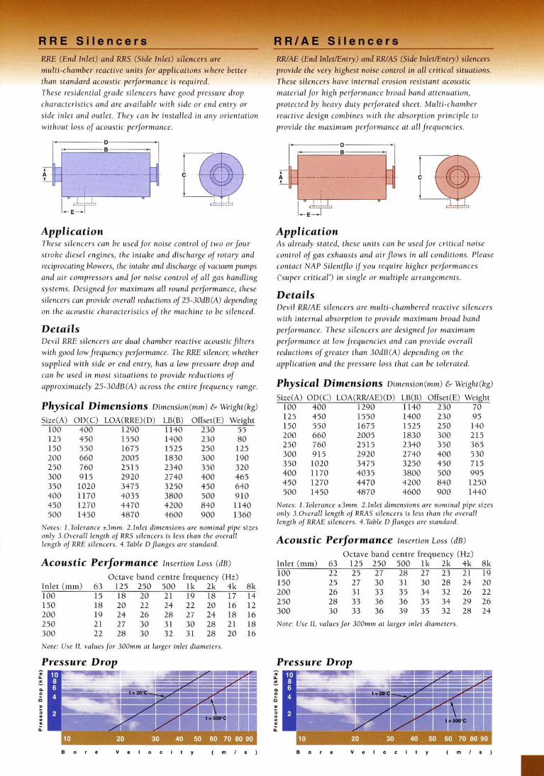
than standard acoustic performance is required. These residential grade silencers have
hese silencers have internal erosion resistant acoustic . . . . __ - . - 1
characteristics and are available with side or end entry or side inlet and outlet. They can be installed in any orientation without loss of acoustic performance.
protected by heavy duty perforated sheet. Multi-chamber . -
reactive design combines with the absorption principle to provide the maximum performance at all frequencies.
Application These silencers can be usedfor noise control of two or four stroke diesel engines, the inta.ke and discharge of rotary and reciprocating blowers, the intake and discharge of vacuum pumps and air compressors andfor noise control of all gas handling sys tems. Designed for maximum a1 1 round performance, these silencers can provide overall reductions of25-30dB(A) depending on the acoustic characteristics of the machine to be silenced.
Application As already stated, these units can be usedfor critical noise control of gas exhausts and airjlows in all conditions. Please contact NAP Silentflo if you require higher performances ('super critical') in single or multiple arrangements.
Details Devil RWAE silencers are multi-chambered reactive silencers with internal absorption to provide maximum broad band performance. These silencers are designed for maximum performance at low frequencies and can provide overall reductions of greater than 30dB (A) depending on the application and the pressure loss that can be tolerated.
Details Devil R E silencers are dual chamber reactive acoustic filters with good lowfrequency performance. The RRE silence5 whether supplied with side or end entry, has a low pressure drop and can be used in most situations to provide reductions of approximately 25-30dB(A) across the entirefrequency range. Physical Dimensions Dimension(mm) 15 Weight(kg)
Size(A) OD(C) LOA(RR/AE)(D) LB(B) Offset(E) Weight 100 400 1290 1140 230 70 125 450 1550 1400 230 95 150 550 1675 1525 250 140 200 660 2005 1830 300 215 250 760 2515 2340 350 365 300 915 2920 2740 400 530 350 1020 3475 3250 450 715 400 1170 4035 3800 500 995 450 1270 4470 4200 840 1250 500 1450 4870 4600 900 1440
Physical Dimensions Dimension(mm) C Weight(kg)
Offset(E) Weight 230 55
Notes: 1 .Tolerance i3mm. 2.Inlet dimensions are nominal pipe sizes only 3.0verall length ojRRAS silencers is less than the overall length oj RRAE silencers. 4.Table D flanges are standard.
Notes: 1.Tolerance J m m . 2.lnlet dimensions are nominal pipe sizes only 3.0verall length of RRS silencers is less than the overall length ojRRE silencers. 4.Table Dflanges are standard. Acoustic Performance Insertion LOSS ( d ~ )
Octave band centre frequency (Hz) Inlet (mm) 63 125 250 500 l k 2k 4k 8k 100 22 25 27 28 27 23 21 19 150 25 27 30 31 30 28 24 20 200 26 31 33 35 34 32 26 22 250 28 33 36 36 35 34 29 26 300 30 33 36 39 35 32 28 24
Note: Use IL values for 300mm at larger inlet diameters.
Acoustic Performance Insertion LOSS ( d ~ )
Octave band centre frequency (Hz) Inlet (mm) 63 125 250 500 lk' 2k 4k 8k 100 15 18 20 21 19 18 17 14
Note: Use IL values for 300mm at larger inlet diameters.
Pressure Drop Pressure Drop
B o r e V e l I t y ( m l s )
Alp, The the 1
tole] engi sets,
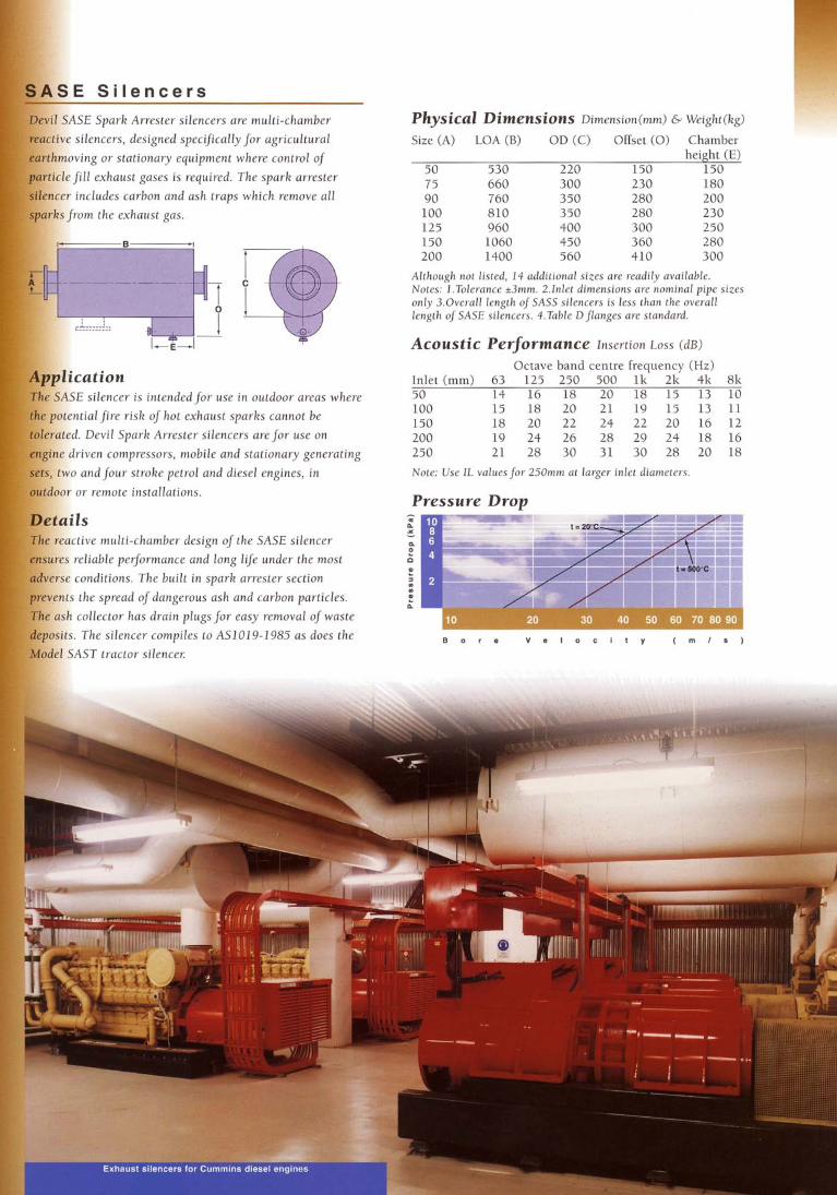
E S i l e n c e r s ASE Spark Arrester silencers are multi-chamber silencers, designed specifically for agricultural
wing or stationary equipment where control of ,fill exhaust gases is required. The spark arrester includes carbon and ash traps which remove all
from the exhaust gas.
tion silencer is intendedfor use in outdoor areas where
tial fire risk of hot exhaust sparks cannot be
, Devil Spark Arrester silencers are for use on riven compressors, mobile and stationary generating andfour stroke petrol and diesel engines, in
or remote installations.
Zs rctive multi-chamber design of the SASE silencer i reliable performance and long life under the most ? conditions. The built in spark arrester section
the spread of dangerous ash and carbon particles. collector has drain plugsfor easy removal of waste . The silencer compiles to AS1019-1985 as does the AST tractor silencer
Physical Dimensions Dimension(mm) C Weiglzt(kg>
Size (A) LOA (B) OD (C) Offset (0 ) Chamber height (El
150
Although not listed, 14 additional sizes are readily available. Notes: 1.Tolerance k3mrn. 2.Inlet dimensions are nominal pipe sizes only 3.0verall length of SASS silencers is less than the overall length of SASE silencers. 4.Table Dflanges are standard.
Acoustic Performance Insertion Loss (dB)
Octave band centre frequency (Hz) Inlet (mm) 63 125 250 500 l k 2k 4k 8k 50 14 16 18 20 18 15 13 10
Note: Use IL values for 250mm at larger inlet diameters.
Pressure Drop
levels from the noisy machine I f nolse measuring equipmet lirectivlty and dlstance attenuat~on ~n order to establish a is available, an octave band analys~s is preferred but in all suitable criterion. The use of a dB(A) criterion allows the cases a dB(A) measurement is required. I f a sound level meter is not available manufacturers can usually provide the unsilenced noise level of compressors, blowers, turbines, pumps or diesel engines.
A c o u s t i c C r i t e r i o n
silencer performance to be established by a single number but technically is less accurate.
Example Si lencer Performance
The difference between the unsilenced exhaust spectrum and the acceptable noise level criterion defines the minimum insertion loss that must be provided by the silencer As an example a diesel engine is required to meet a criterion of NR75 due to the proximity ofa nearby residential area. The attenuation required is given by following the procedure set out below.
Once the machine noise level has been found the acoustic criterion must be established. For normal industrial working environments an acceptable criterion is NR85 or 90dB(A) at 1 metre but for commercial and occupied areas more strict criteria are often applied. A simplified method of setting a criterion is switching the noisy machine on and off, the difference in noise levels representing the required reduction. For a list of acceptable noise levels in community areas the reader is referred to AS1055-1989 'Noise Assessment in Residential Areas' andfor internal areas AS2107-1987 'Ambient Sound Levels for areas of occupancy within buildings.
Freq, Hz 125 250 500 lk 2k 4k dB(A) LP* 105 98 92 90 88 82 96 Criterion NR75 87 82 77 75 73 70 81 IL 18 16 15 15 15 12 15 *Unsilenced engine noise level at 1 metre.
The correct silencer for the given attenuation has the minimum performance defined in all octave bands, or alternatively an overall performance of 15dB(A).
Silencer Selection Table MACHINE TYPE LOCATION RAE RIE RRE RR/AE SASE
Blowers Centrifugal Suction J J J J Discharge J J J
Positive Displacement Suction J J Dischar~e J
Sliding Vane Suction J Discharge J
Compressors Reciprocating Suction J J J Discharge J ---
Screw Suction J J Discharge J
Sliding Vane Suction J Discharge J
Engines Naturally Aspirated Intake J J Diesel & Petrol Exhaust J J J J
Turbo Charged Intake J J Exhaust J J J J
Turbines Gas Intake J Exhaust J
~
Steam Intake J Exhaust J
Vacuum Pumps Centrifugal Suction J Discharge J
Rotary Suction J
.... .. Discharge
.. . . . . . J J J
Sliding Vane Suction J Discharge J J J
Valves Unloading Ejectors J
Marine Engines Intake J Exhaust J J
Agricultural Engine Powered Intake J J Earthmoving Exhaust J J J
T v o i c a l S p e c i f i c a t i o n
The equipment shall be provided with a suitably configured
exhaust pipe and silencer: The silencer shall be selected,
designed andfabricated to ensure compliance with the noise
criteria specified.
The exhaust pipe may be manufactured from 1.6mm thick stainless steel Grade 304 or minimum 3mm mild steel
piping. Mild steel flanges may be used. All exposed piping
and silencers in noise sensitive areas shall be clad and
acoustically insulated with flexible grade mineral wool
insulation and metal cased (suitable for temperatures to
650°C if required). Insulation sections shall fit around the
exhaust pipe and silencers neatly and accurately without gaps and shall be secured in a commercial and workmanlike
manner: Loose insulation shall be sealed with Melinex only i f SMF Conditions apply andfor site work only.
Flanged sections of piping shall be insulated, but must be
readily exposed to enable inspection or unbolting ofjoints.
Gaskets must be used.
The exhaust silencer shall be of the reactive multi-chamber
type, constructed of welded steel with internal absorption if required, designed for horizontal or vertical installation and
treated with high temperature paint in accordance with the
specijication. The silencer shall be factory built and
delivered to site including matching Table D inlet and outlet
flanges. The silencer shall be supplied to enable connection
to the machine and the supporting structure viaflexible coil
spring vibration isolators and stainless steel bellows.
Silencer shall be a NAP Silentflo Model with side
entry and end exhaust to suit aflow of m3/s at a
temperature of500°C. The silencer back pressure shall not
exceed 2.5kPa. Total system pressure drop shall not exceed
kPa.
Silencer insertion loss shall be nominated in octave bands from 63 to 8000Hz and the manufacturer shall provide
supporting documentation. Silencer manufacturer is to
submit evidence demonstrating that the items can be
manufactured in accordance with the requirements of
AS3902. Manufacturer is to have a minimum of 5 years
experience in the design and manufacture of silencer exhaust
systems and to submit reference lists of customers, similar
projects and equipment silenced.
NAP SILENTFLO T H E E X P E R T S I N N O I S E C O N T R O L
A B N 13' 0 7 1 4 4 3 886