using the phoenix composting - advanced composting systems · pdf fileusing the phoenix...
TRANSCRIPT
© 2007, Advanced Composting Systems,LLC, all rights reserved.
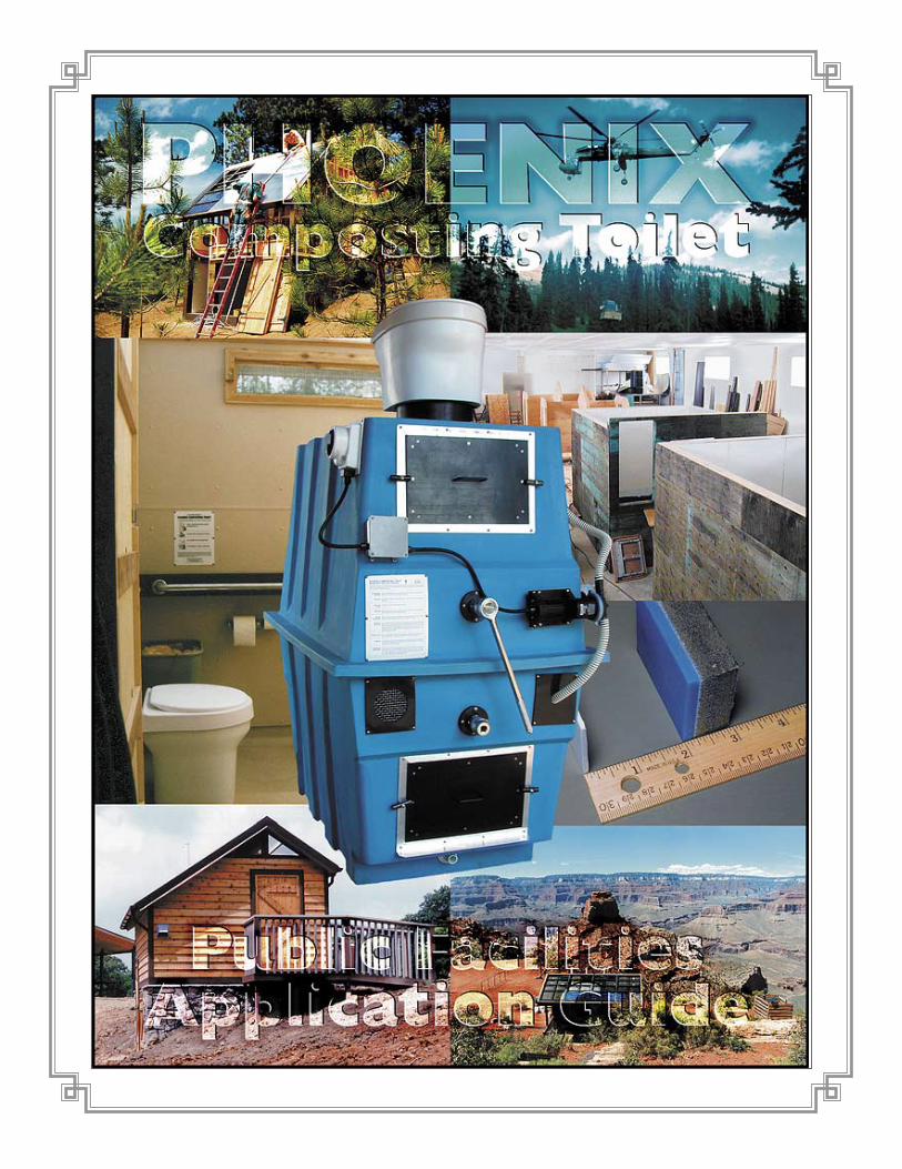
Using the Phoenix CompostingToilet System in Public Facilities
Advanced Composting Systems, LLC195 Meadows Road • Whitefish, Montana 59937
Phone: 406-862-3854 • Fax: 406-862-3855Email: [email protected]
Internet: http://www.compostingtoilet.com
Revised & ExpandedFebruary, 2007
An Information & Application Guide
Public Facility Application Guide, 2005 Edition Page a3
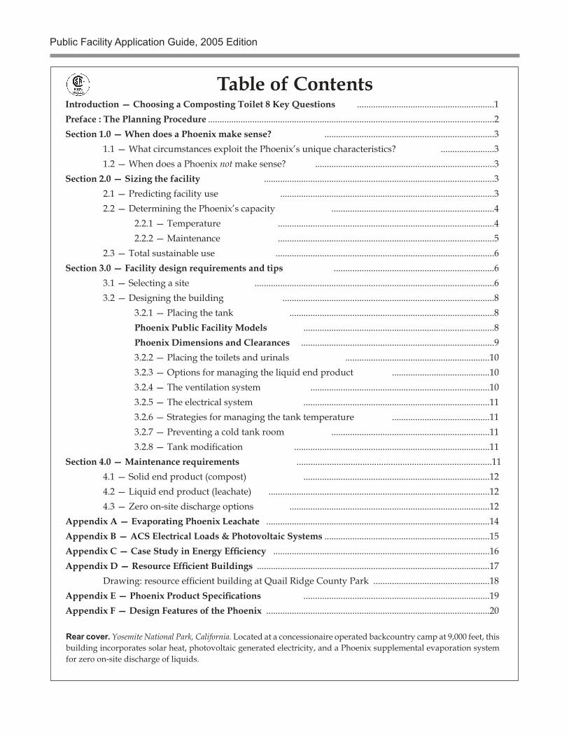
Table of ContentsIntroduction — Choosing a Composting Toilet 8 Key Questions ...........................................................1Preface : The Planning Procedure ...........................................................................................................................2Section 1.0 — When does a Phoenix make sense? .........................................................................3 1.1 — What circumstances exploit the Phoenix’s unique characteristics? .......................3 1.2 — When does a Phoenix not make sense? .............................................................................3Section 2.0 — Sizing the facility ...................................................................................................3 2.1 — Predicting facility use ............................................................................................3 2.2 — Determining the Phoenix’s capacity ......................................................................4 2.2.1 — Temperature .............................................................................................4 2.2.2 — Maintenance .............................................................................................5 2.3 — Total sustainable use ..............................................................................................6Section 3.0 — Facility design requirements and tips .....................................................................6 3.1 — Selecting a site .......................................................................................................6 3.2 — Designing the building ...........................................................................................8 3.2.1 — Placing the tank ........................................................................................8 Phoenix Public Facility Models ..................................................................................8 Phoenix Dimensions and Clearances ...................................................................................9 3.2.2 — Placing the toilets and urinals ..............................................................10 3.2.3 — Options for managing the liquid end product ..........................................10 3.2.4 — The ventilation system .............................................................................10 3.2.5 — The electrical system ................................................................................11 3.2.6 — Strategies for managing the tank temperature ..........................................11 3.2.7 — Preventing a cold tank room ....................................................................11 3.2.8 — Tank modification ....................................................................................11Section 4.0 — Maintenance requirements ...................................................................................11 4.1 — Solid end product (compost) ................................................................................12 4.2 — Liquid end product (leachate) ...............................................................................................12 4.3 — Zero on-site discharge options ......................................................................................12Appendix A — Evaporating Phoenix Leachate ................................................................................................14Appendix B — ACS Electrical Loads & Photovoltaic Systems .......................................................................15Appendix C — Case Study in Energy Efficiency .............................................................................................16Appendix D — Resource Efficient Buildings ....................................................................................................17 Drawing: resource efficient building at Quail Ridge County Park ..................................................18Appendix E — Phoenix Product Specifications ................................................................................19Appendix F — Design Features of the Phoenix ................................................................................................20
Rear cover. Yosemite National Park, California. Located at a concessionaire operated backcountry camp at 9,000 feet, this building incorporates solar heat, photovoltaic generated electricity, and a Phoenix supplemental evaporation system for zero on-site discharge of liquids.
Public Facility Application Guide, 2005 Edition Page 1
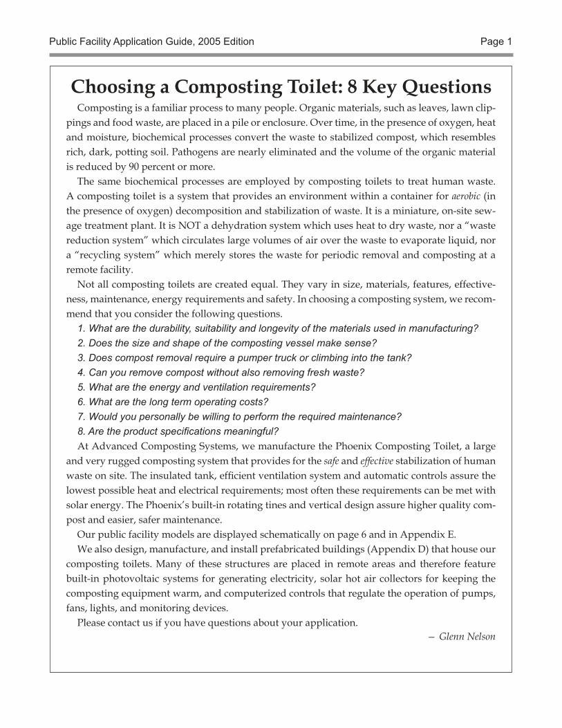
Choosing a Composting Toilet: 8 Key QuestionsComposting is a familiar process to many people. Organic materials, such as leaves, lawn clip-
pings and food waste, are placed in a pile or enclosure. Over time, in the presence of oxygen, heat and moisture, biochemical processes convert the waste to stabilized compost, which resembles rich, dark, potting soil. Pathogens are nearly eliminated and the volume of the organic material is reduced by 90 percent or more.
The same biochemical processes are employed by composting toilets to treat human waste. A composting toilet is a system that provides an environment within a container for aerobic (in the presence of oxygen) decomposition and stabilization of waste. It is a miniature, on-site sew-age treatment plant. It is NOT a dehydration system which uses heat to dry waste, nor a “waste reduction system” which circulates large volumes of air over the waste to evaporate liquid, nor a “recycling system” which merely stores the waste for periodic removal and composting at a remote facility.
Not all composting toilets are created equal. They vary in size, materials, features, effective-ness, maintenance, energy requirements and safety. In choosing a composting system, we recom-mend that you consider the following questions.
1. What are the durability, suitability and longevity of the materials used in manufacturing?2. Does the size and shape of the composting vessel make sense? 3. Does compost removal require a pumper truck or climbing into the tank?4. Can you remove compost without also removing fresh waste?5. What are the energy and ventilation requirements?6. What are the long term operating costs?7. Would you personally be willing to perform the required maintenance?8. Are the product specifications meaningful?At Advanced Composting Systems, we manufacture the Phoenix Composting Toilet, a large
and very rugged composting system that provides for the safe and effective stabilization of human waste on site. The insulated tank, efficient ventilation system and automatic controls assure the lowest possible heat and electrical requirements; most often these requirements can be met with solar energy. The Phoenix’s built-in rotating tines and vertical design assure higher quality com-post and easier, safer maintenance.
Our public facility models are displayed schematically on page 6 and in Appendix E.We also design, manufacture, and install prefabricated buildings (Appendix D) that house our
composting toilets. Many of these structures are placed in remote areas and therefore feature built-in photovoltaic systems for generating electricity, solar hot air collectors for keeping the composting equipment warm, and computerized controls that regulate the operation of pumps, fans, lights, and monitoring devices.
Please contact us if you have questions about your application.— Glenn Nelson
Public Facility Application Guide, 2005 Edition Page 2
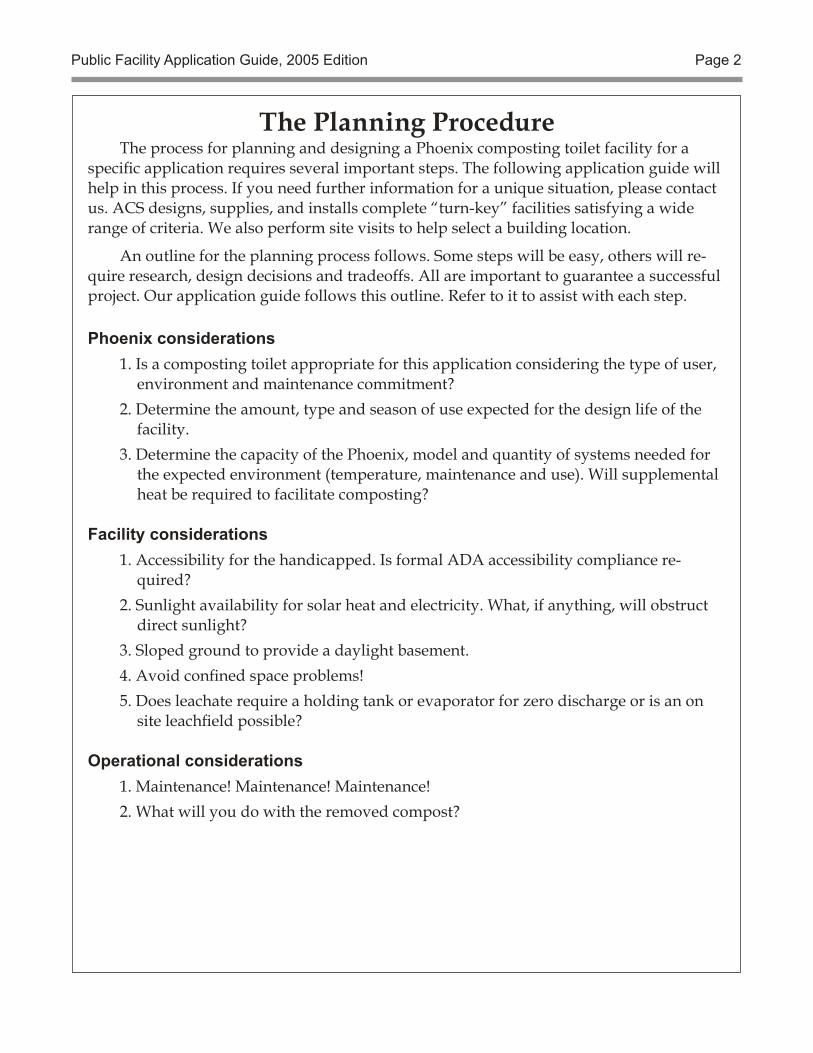
The Planning ProcedureThe process for planning and designing a Phoenix composting toilet facility for a
specific application requires several important steps. The following application guide will help in this process. If you need further information for a unique situation, please contact us. ACS designs, supplies, and installs complete “turn-key” facilities satisfying a wide range of criteria. We also perform site visits to help select a building location.
An outline for the planning process follows. Some steps will be easy, others will re-quire research, design decisions and tradeoffs. All are important to guarantee a successful project. Our application guide follows this outline. Refer to it to assist with each step.
Phoenix considerations1. Is a composting toilet appropriate for this application considering the type of user,
environment and maintenance commitment?2. Determine the amount, type and season of use expected for the design life of the
facility.3. Determine the capacity of the Phoenix, model and quantity of systems needed for
the expected environment (temperature, maintenance and use). Will supplemental heat be required to facilitate composting?
Facility considerations 1. Accessibility for the handicapped. Is formal ADA accessibility compliance re-
quired?2. Sunlight availability for solar heat and electricity. What, if anything, will obstruct
direct sunlight?3. Sloped ground to provide a daylight basement.4. Avoid confined space problems! 5. Does leachate require a holding tank or evaporator for zero discharge or is an on
site leachfield possible?
Operational considerations1. Maintenance! Maintenance! Maintenance! 2. What will you do with the removed compost?
Public Facility Application Guide, 2005 Edition Page 3
§ 1.0 — When does a Phoenix make sense?
Certain management and site conditions sug-gest a composting toilet while others are inimical to its success; employing a Phoenix does not al-ways make sense. A better alternative may be a conventional system, vault toilet or pit privy.
§ 1.1 — What circumstances exploit the Phoenix’s unique characteristics?
• At heavily used backcountry sites where access and transportation are limited, the Phoenix needs only simple manual maintenance.
• In environmentally sensitive areas such as lakeshores, the Phoenix offers zero dis-charge.
• Where no utility electricity is available, a pho-tovoltaic system can be used to supply the Phoenix’s minimal electrical needs.
• Where water scarcity precludes flush toilets, the waterless Phoenix will operate. To facilitate maintenance, provide a small amount of pressurized water from a rain water cistern.
• Winter freezing conditions which may dam-age pipes and fixtures in a conventional flush system will not damage the Phoenix. As long as the tank is in a heated space, the composting process continues. A drain-back water supply for sink faucets offers the same freeze protection.
• In high density campgrounds, a Phoenix facility’s odorless toilet room and aerobic decomposition are more aesthetic than a vault toilet’s penetratingly offensive odor.
§ 1.2 — When does a Phoenix not make sense?
• Consistently cold conditions that reduce the Phoenix’s capacity below use require-ments will result in incomplete stabiliza-tion of the end product and in unhealthy and unpleasant maintenance.
• If sewer and water connections are available, a flush system may be less expensive.
• Severe vandalism could destroy a com-posting system. A hardened concrete vault and toilet building offer more immunity.
• Inconsistent or improper maintenance will reduce tank capacity and composting ef-ficiency resulting in poorly decomposed end product.
§ 2.0 — Sizing the facilityHow many tanks and how many toilets will
a facility need? The answers depend on total annual use, and peak daily use. “Uses” should not be confused with the number of people in an area, for “uses per person” varies depending on the nature of visitor activities in an area.
The number of total annual uses determines how many tanks are needed. The peak daily use determines how many toilets must be installed (a tank can accommodate two toilets).
When calculating rates of use, one often needs to account for the accelerated rates of use that can occur following the opening of a new facility (“if you build it, they will come and go”).
The Phoenix’s capacity is rated in average uses per day and varies according to the tank’s temperature, the type of use, and the frequency and quality of maintenance.
§ 2.1 — Predicting facility useThe total annual use for a facility can be
inferred (with varying degrees of accuracy) from a variety of data. Here are a few common situations:
Highway rest areas. The Federal Highway Administration has quantified toilet use as a function of traffic counts. Thus historical traffic count data can be used to estimate current use and project future use.
Existing facilities. The amount of use at an existing toilet facility can be calculated from:
• Water consumption, provided that the water is metered. This is true even when water is used only for washing, as in the case of a facility equipped with pit toilets.
• The volume of waste pumped from a vault or portable toilet (20 uses/gal., 5 uses/liter).
Public Facility Application Guide, 2005 Edition Page 4
• The consumption of toilet paper. For example, 90 uses per roll seems to be the norm for restricted delivery holders.
• Door counters. We sell an automated door counter that can be retrofitted to any facil-ity with a toilet room door. This, obviously, is the best method for ascertaining the amount of use.
Campsite capacity and occupancy. In campgrounds, the daily per capita use of toilet facilities is a function of access, recreational op-portunities, and the amount of time spent in the area:
• At campgrounds accessible by vehicles, daily per capita use ranges from 3 to 5. The av-erage group numbers 3 persons, but may be larger in campgrounds that attract a high percentage of family use. Campgrounds offering close-at-hand recreational op-portunities, such as swimming or fishing, experience longer stays and higher per capita use than sites that are used mostly for overnight stops.
• At backcountry campgrounds, daily per capita use ranges from 2 to 3. Tallies from trailhead registers, and the number of campsites, can be used for estimating backcountry facility use.
• At facilities for day hikers, daily per capita use is between zero and one. Tallies from trailhead registers, and/or vehicle traffic counts, can be used to estimate the amount of day use.
Parking areas. The number of parking spaces, visitor turnover rates, and remoteness affect the rate of toilet use.
§ 2.2 — Determining the Phoenix’s ca-pacity
Capacity is the amount of use (expressed as “uses per day”) the Phoenix can sustain while producing stabilized, non-offensive, liquid and solid end products with low coliform counts, solids with a moist but not saturated texture and liquids with a high ratio of nitrate to ammonia nitrogen. Removing compost from a Phoenix
that has been properly maintained, and used within its capacity rating, will not be an un-pleasant operation.
Our ratings are conservative, and are derived from operational experience. We have equipped representative facilities with data loggers to re-cord temperature and use and we visit many Phoenix installations to retrieve use data and to assist with removing compost. Our extensive hands-on experience with the capacity-envi-ronment-maintenance relationship has allowed us to quantify capacity as a function of mainte-nance and ambient temperature. We continue to refine our numbers by monitoring existing facilities, and through an ongoing research and development program.
§ 2.2.1 — TemperatureThe rate of decomposition within a Phoenix
primarily depends on the internal temperature of the compost pile. The higher the pile’s tem-perature, the more rapid the decomposition, and thus the higher the capacity of the tank. Moreover, a relatively small increase in compost temperature results in a relatively large increase in the rate of decomposition.
Proper temperature management is critical to successful composting. Two temperatures affect the composting process:
Ambient temperature is the temperature of the tank’s surroundings and ventilation air sup-ply. This temperature can differ significantly from the out-of-doors air temperature, and/or from the temperature of the ground. A low ambient temperature increases the heat loss from the Phoenix and depresses the compost temperature.
Compost temperature is the temperature of the compost pile. When significant composting ac-tivity occurs, the compost temperature almost always will be higher than the ambient tempera-ture. Conversely, a low compost temperature indicates a “cold tank” and a lack of significant composting activity.
Compost self-heating. The biochemical reac-tions of the composting process produce carbon
Public Facility Application Guide, 2005 Edition Page 5
dioxide and water, and release energy, heating the compost pile. The rate of the biological and chemical processes involved in composting approximately doubles for every 18°F (10° C) of increase in compost temperature. Self-heat-ing occurs when the pile has sufficient fuel, moisture and oxygen, and when the ambient temperature is high enough that the reactions can be sustained. The Phoenix’s low ventilation rate and insulated tank hold the heat generated by the compost pile.
Composting activity is very slow at ambient temperatures below 55° F (10° C), but accelerates rapidly as the ambient temperature rises. Our specifications assume a minimum ambient tem-perature is 65° F (19° C).
Ventilative and evaporative cooling. The Phoenix is kept odorless by drawing air through the toilet and tank, and expelling it through a vent in the roof.
Air flowing through the Phoenix increases
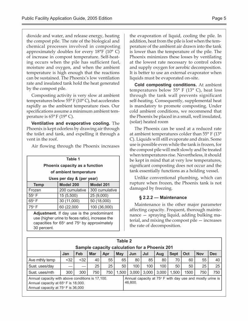
Table 1Phoenix capacity as a function
of ambient temperatureUses per day & (per year)
Temp Model 200 Model 201Frozen 200 cumulative 300 cumulative55o F 15 (5,500) 25 (9,000) 65o F 30 (11,000) 50 (18,000)75o F 60 (22,000 100 (36,000)
Adjustment. If day use is the predominant use (higher urine to feces ratio), increase the capacities for 65o and 75o by approximately 30 percent.
the evaporation of liquid, cooling the pile. In addition, heat from the pile is lost when the tem-perature of the ambient air drawn into the tank is lower than the temperature of the pile. The Phoenix minimizes these losses by ventilating at the lowest rate necessary to control odors and supply oxygen for aerobic decomposition. It is better to use an external evaporator when liquids must be evaporated on-site.
Cold composting conditions. At ambient temperatures below 55° F (13° C), heat loss through the tank wall prevents significant self-heating. Consequently, supplemental heat is mandatory to promote composting. Under cold ambient conditions, we recommend that the Phoenix be placed in a small, well insulated, (solar) heated room
The Phoenix can be used at a reduced rate at ambient temperatures colder than 55° F (13° C). Liquids will still evaporate and drain. Some use is possible even while the tank is frozen, for the compost pile will melt slowly and be treated when temperatures rise. Nevertheless, it should be kept in mind that at very low temperatures, significant composting does not occur and the tank essentially functions as a holding vessel.
Unlike conventional plumbing, which can rupture when frozen, the Phoenix tank is not damaged by freezing.
§ 2.2.2 — MaintenanceMaintenance is the other major parameter
affecting capacity. Frequent, thorough mainte-nance — spraying liquid, adding bulking ma-terial, and mixing the compost pile — increases the rate of decomposition.
Table 2Sample capacity calculation for a Phoenix 201
Jan Feb Mar Apr May Jun Jul Aug Sept Oct Nov DecAve mthly temp <32 <32 40 55 65 80 85 80 70 60 55 40Sust. uses/day — — 25 25 50 100 100 100 50 50 25 25Sust. uses/mth 300 300 750 750 1,500 3,000 3,000 3,000 1,500 1500 750 750Annual capacity with above conditions is 17,100.Annual capacity at 65o F is 18,000.Annual capacity at 75o F is 36,000
Annual capacity at 75o F with day use and mostly urine is 46,800.
Public Facility Application Guide, 2005 Edition Page 6
Moisture management. The proper moisture level and porosity of the compost pile (from the addition of bulking agents, such as wood shav-ings) must be established. The Phoenix includes a liquid spray system to help maintain moisture levels. The addition of bulking material is a simple task when performed frequently. The Phoenix includes built-in rotating tines to mix the bulking material with waste; additional rak-ing often is unnecessary.
Pile aeration management. Because raw fecal matter is too wet and non-porous to compost, it must be mixed with a bulking agent — we rec-ommend white wood shavings — to provide the structural support and the airspaces necessary for aerobic decomposition. The bulking agent must be thoroughly mixed into the pile. The more frequently the bulking agent is added to the pile, the less frequently mixing the pile will be required.
User behavior. At day use facilities, the urine-to-feces ratio is higher than at overnight facilities. This translates into an increase in capacity of 30 percent.
§ 2.3 — Total sustainable useThe amount of use that the Phoenix can sus-
tain in any month correlates reasonably well with the average ambient temperature for that month. Use at 150 percent of capacity can be sustained for long periods as long as monthly averages are within ratings. Even higher rates of use can be accommodated for short periods, such as a Fourth of July Weekend. The capacity of prop-erly maintained Phoenix systems for different ambient temperatures is shown in Table 1.
§ 3.0 — Facility design and site selec-tion requirements and tips
§ 3.1 — Selecting a siteChoosing a site for a Phoenix facility will have
dramatic effects on system capacity, building de-sign, user accessibility, energy use, maintenance effort, and construction cost. Therefore, thought-fully consider the needs of the composting toilet and maintenance personnel as well as visitors when selecting a site.
Solar energy considerations. Photovoltaic panels and solar heat collectors require unob-structed access to direct sunlight. Therefore, the roofs of buildings with roof mounted collectors and PV panels must face south.
Sloped terrain. The Phoenix can be installed on level ground, but taking advantage of sloped terrain will reduce the excavation requirements and allow easier access to the tanks for main-tenance. It is more convenient for maintenance persons to enter a daylight basement through a vertical door than to descend stairs into a full basement. A daylighted basement can also be smaller, since large doors in front of each Phoenix permit the required maintenance area to extend outside the building. We recommend a daylighted basement if the terrain slopes 20 degrees or more. Access to the toilet rooms is provided easily by extending a small deck and ramp to the hillside.
Flat terrain requires a full basement or an elevated building. Conventional stairs and perhaps active ventilation may be required to avoid a permitted confined space. Providing a 5-foot area in front of the Phoenixes, artificial lighting, and reflective white walls, facilitates maintenance. Avoid a flooded basement by building above maximum high ground water, elevating the building slightly, sloping soil away
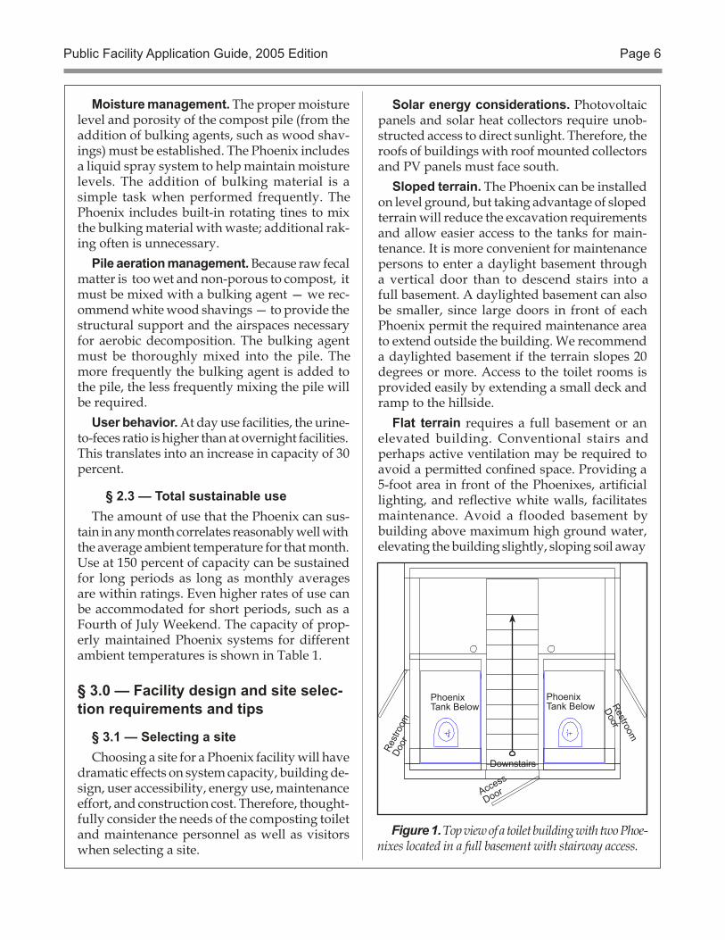
Figure 1. Top view of a toilet building with two Phoe-nixes located in a full basement with stairway access.
PhoenixTank Below
PhoenixTank Below
Access
Door
Rest
room
Door
Downstairs
Restroom
Door
Public Facility Application Guide, 2005 Edition Page 7
from the foundation, and adhering to good drainage practices.If high ground water or impenetrable rock precludes excavation,
an elevated building is necessary. A stairway, or an extended ramp
for accessibility may be re-quired.
Disposal of liquids. Suit-able conditions must exist for disposing of the liquid end product from the Phoenix. If local conditions, such as high ground water, preclude a leach field, then provide a holding tank, a raised bed evapotranspiration system, or a Phoenix liquid evapo-ration system. A holding tank requires strict attention to prevent overflows.
Preventing unauthorized dumping and vandalism. If the Phoenix is located near a parking area, the design must prevent the emptying of recreational vehicle hold-ing tanks into the toilet. Lo-cate the building far enough away from the parking area that drain hoses cannot reach it, or elevate the building slightly so that the toilet is above an RV’s holding tank. Provide a waste dump near the building that offers a con-venient alternative, and post signs advising users against dumping chemical toilets and holding tanks into the Phoenix.
Similarly, locate trash cans and cigarette disposal con-tainers immediately outside the building to reduce misuse of the Phoenix. If trash collec-tion needs to be minimized, a trash container inside the toi-let room will intercept those intent upon misuse, while not attracting others to dispose of their trash.
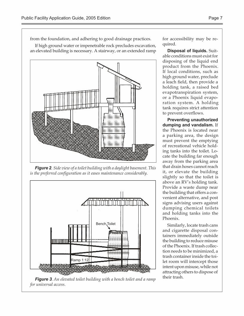
Figure 2. Side view of a toilet building with a daylight basement. This is the preferred configuration as it eases maintenance considerably.
Figure 3. An elevated toilet building with a bench toilet and a ramp for universal access.
Public Facility Application Guide, 2005 Edition Page 8
§ 3.2 — Designing the buildingNearly any building design satisfying the
following conditions is compatible with the Phoenix:
• The Phoenix must be located directly below the toilet(s).
• The tank must rest upon a smooth, level, flat surface.
• Convenient access, good lighting and venti-lation, and adequate space in front of the Phoenix, must be provided for mainte-nance operations.
• Adequate space for storing the bulking agent and supplies must be provided.
• The Phoenix’s 4-inch DWV ventilation pipe should be supported by the building framing, and extend above the roof ridge for proper air flow.
• A drain, holding tank, or evaporation system for the liquid end product must be provided.
• Electricity must be available for the Phoe-nix’s ventilation fan, pump(s), and other systems.
• The tank area must be maintained at or above the temperature upon which the Phoenix’s capacity rating is based.
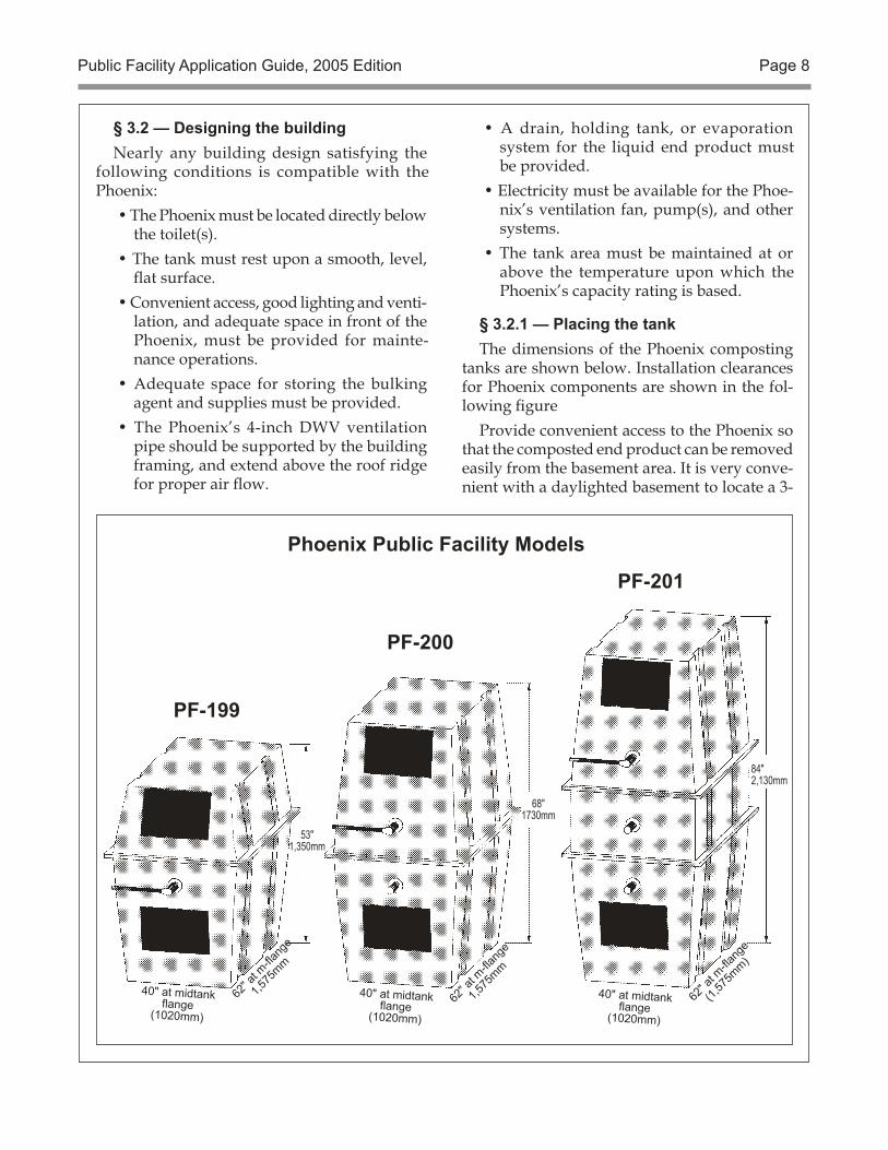
§ 3.2.1 — Placing the tankThe dimensions of the Phoenix composting
tanks are shown below. Installation clearances for Phoenix components are shown in the fol-lowing figure
Provide convenient access to the Phoenix so that the composted end product can be removed easily from the basement area. It is very conve-nient with a daylighted basement to locate a 3-
Phoenix Public Facility Models
62" a
t m-fla
nge
(1,57
5mm)
40" at midtank flange
(1020mm)
PF-201
53"1,350mm
62" a
t m-fla
nge
1,575
mm
40" at midtank flange
(1020mm)
PF-199
40" at midtank flange
(1020mm)
68"1730mm
PF-200
62" a
t m-fla
nge
1,575
mm
84"2,130mm
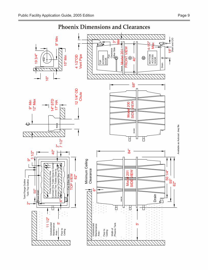
Public Facility Application Guide, 2005 Edition Page 9
Phoenix Dimensions and Clearances
Public Facility Application Guide, 2005 Edition Page 10
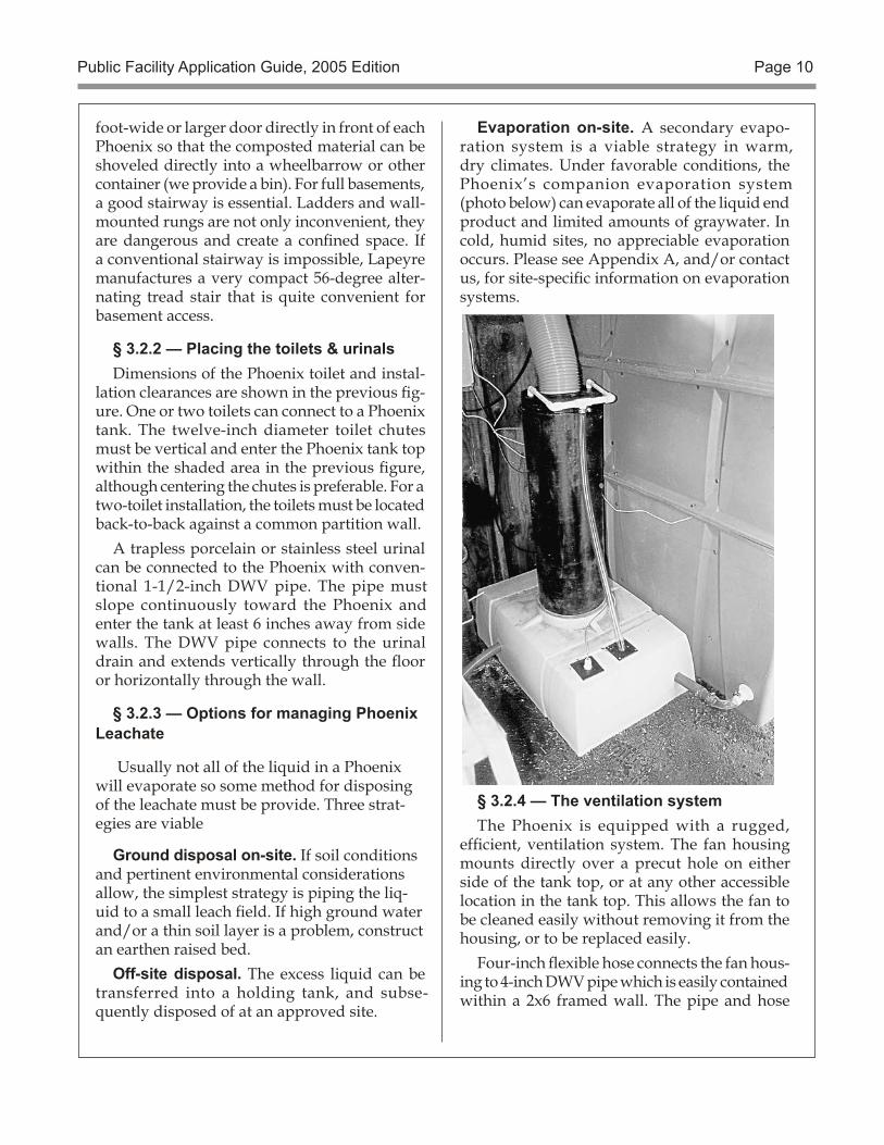
Evaporation on-site. A secondary evapo-ration system is a viable strategy in warm, dry climates. Under favorable conditions, the Phoenix’s companion evaporation system (photo below) can evaporate all of the liquid end product and limited amounts of graywater. In cold, humid sites, no appreciable evaporation occurs. Please see Appendix A, and/or contact us, for site-specific information on evaporation systems.
§ 3.2.4 — The ventilation systemThe Phoenix is equipped with a rugged,
efficient, ventilation system. The fan housing mounts directly over a precut hole on either side of the tank top, or at any other accessible location in the tank top. This allows the fan to be cleaned easily without removing it from the housing, or to be replaced easily.
Four-inch flexible hose connects the fan hous-ing to 4-inch DWV pipe which is easily contained within a 2x6 framed wall. The pipe and hose
foot-wide or larger door directly in front of each Phoenix so that the composted material can be shoveled directly into a wheelbarrow or other container (we provide a bin). For full basements, a good stairway is essential. Ladders and wall-mounted rungs are not only inconvenient, they are dangerous and create a confined space. If a conventional stairway is impossible, Lapeyre manufactures a very compact 56-degree alter-nating tread stair that is quite convenient for basement access.
§ 3.2.2 — Placing the toilets & urinalsDimensions of the Phoenix toilet and instal-
lation clearances are shown in the previous fig-ure. One or two toilets can connect to a Phoenix tank. The twelve-inch diameter toilet chutes must be vertical and enter the Phoenix tank top within the shaded area in the previous figure, although centering the chutes is preferable. For a two-toilet installation, the toilets must be located back-to-back against a common partition wall.
A trapless porcelain or stainless steel urinal can be connected to the Phoenix with conven-tional 1-1/2-inch DWV pipe. The pipe must slope continuously toward the Phoenix and enter the tank at least 6 inches away from side walls. The DWV pipe connects to the urinal drain and extends vertically through the floor or horizontally through the wall.
§ 3.2.3 — Options for managing Phoenix Leachate
Usually not all of the liquid in a Phoenix will evaporate so some method for disposing of the leachate must be provide. Three strat-egies are viable
Ground disposal on-site. If soil conditions and pertinent environmental considerations allow, the simplest strategy is piping the liq-uid to a small leach field. If high ground water and/or a thin soil layer is a problem, construct an earthen raised bed.
Off-site disposal. The excess liquid can be transferred into a holding tank, and subse-quently disposed of at an approved site.
Public Facility Application Guide, 2005 Edition Page 11
should slope continuously towards the fan hous-ing so that liquid from rain or condensation will run back to the fan drain.
The 4-inch DWV pipe should exit through the roof near the ridge to avoid potential snow loads and downdrafts. Several shroud arrange-ments can conceal one or several juxtaposed Phoenix and evaporator vent pipes as long as the exhaust air exits several feet above the roof in an upward direction. Do not enclose vents in a louvered cupola.
If the Phoenix is used in subfreezing tem-peratures, insulating the exterior vent pipe and the interior sections passing through cold areas helps prevent condensation and freezing. The room in which the Phoenix is located should be provided with a 25-square-inch (150 cm2) open-ing for ventilation makeup air.
§ 3.2.5 — The electrical systemAll electrical devices and accessories supplied
with the Phoenix operate on direct current: exhaust fans, pumps, light fixtures, and the system monitor and controller. Twelve-volt systems are the default, but 24-volt systems are available (we install both, and can help you determine which is best for your situation). If power from a utility’s electrical grid is not available, electrical requirements can be met from an independent generating system, such as our photovoltaic system. We provide an a.c. power supply for use where 120-volt a.c. is available.
Photovoltaics. If a photovoltaic system is required, provisions must be made for mount-ing the photovoltaic array in an unshaded area, facing south, routing the array output conductors into the building, and locating the batteries and controller in the maintenance area. If utility sup-plied 120-volt a.c. electricity is available, locate an electrical outlet close to the Phoenix for the power supply and controller.
§ 3.2.6 — Strategies for managing the tank temperature
As explained above, the Phoenix must be in a warm environment to compost effectively. The composting process itself generates energy that increases the temperature of the compost pile, but first the compost pile must be warm enough
for sufficient activity to take place. As the tem-perature of the Phoenix is increased, the rate of composting and heat generation increases.
In a below-ground basement, the predominant influence on the temperature of the tank room is the temperature of the ground, which can be much cooler than the outside air temperature during the season of use. Moreover, in some cli-mates the outside air temperature varies greatly throughout a 24-hour period. If the ambient temperature in the Phoenix room drops below 65ºF (19ºC) , the tank cools and the rate of decom-position declines sharply, reducing capacity. At ambient temperatures of 55ºF (13ºC) and lower, composting slows to a virtual standstill.
§ 3.2.7 — Preventing a cold tank roomBasically, there are two strategies:Insulation. The first step is insulating the en-
tire tank room, including the floor, ceiling, doors and foundation walls to reduce heat loss.
Supplemental heat for the tank room and/or tank. In a well insulated room, a relatively modest input of energy results in a significant rise in temperature. We have constructed many buildings incorporating an active solar collector in the roof framing. Hot air from this collector is ducted into the tank room, or to the Phoenix’s air inlet. Conventional electric or gas space heaters also can be used to heat the room.
§ 4.0 — Maintenance requirementsThe Phoenix operates much like a garden
compost pile, requiring adequate food, air, moisture, and heat to support the organisms that transform wastes into a stable end product. The key to successfully operating a composting toilet is maintenance — and the easier it is to perform, the more reliably it will be done. The Phoenix’s design invites proper maintenance with its convenient access doors, rotating tines, separation of liquid from solid waste, and liquid spray system.
• Rotating tines stir the compost pile from outside the tank and control the movement of compost downward to the access area.
Public Facility Application Guide, 2005 Edition Page 12
• Internal baffles separate the liquid and solid end products before the liquid receives secondary aerobic treatment beneath the lower baffles.
• Fresh water and/or treated liquid is au-tomatically sprayed periodically onto the compost pile to inoculate the pile with bac-teria, and to maintain the compost pile’s moisture so that the solid end product is merely moist, not dripping wet, and can be removed easily from the entire tank bottom below the lower tines.
Maintenance requirements and frequency depend upon the amount of use the system receives. Bulking agent must be mixed into the waste pile thoroughly, and trash removed, at least every few hundred uses. A heavily used system requires frequent attention and consid-erable bulking agent (approximately one gallon per 100 uses). Locate a storage bin for bulking agent and a container for liberated trash in a convenient location near the Phoenix.
Waste pile moisture must be checked and either more bulking agent or liquid added as needed. Systems in hot, dry climates, or systems that are used very lightly, require more attention to moisture control. Keeping the waste pile moist also prevents fires from vandalism or misuse. All Phoenixes include a programmable automatic spray system that uses liquid end product and/or fresh water to moisten the compost pile periodically.
Under many circumstances users can add bulking material through the toilet after each use, a “wood shavings flush.” This reduces mix-ing requirements so that periodically rotating the tines is sufficient to maintain a homogeneous mixture.
We strongly recommend keeping a log of con-ditions and actions (e.g. door counter readings, amount of bulking agent added, compost pile height) for a historical record and continuity among maintenance persons. We provide a suggested for-mat and a get-started set of log pages along with our operating manual. The complete Phoenix Opera-tion and Maintenance Instructions is available on our website (www.compostingtoilet.com) as a PDF.
§ 4.1 — Solid end product (compost)The amount of end product, and the frequency
of its removal from the Phoenix, depends upon the amount of use, the rate of decomposition, and the quality of maintenance the system re-ceives. The volume of finished end product is reduced by evaporation, draining (which also carries away dissolved and suspended solids), and decomposition. Coarse wood shavings, recommended for a bulking agent, do not de-compose completely. However, they do compact and smaller particles fill some of the air voids.
Finished material should be removed from the Phoenix at least every two years. Approximately 12 bins of material (90 U.S. gallons, 350 liters, or 12 cubic feet) should be removed from beneath the tines. The amount of solid end product which must be removed from the Phoenix so use is sustainable will be about 30 liters (8 gallons) for every 1,000 uses, less if the tank is used at a lower rate or receives mostly urine. If this is too much, some material can be reintroduced at the top of the tank to maintain the compost level or some loosened material can be left in the clean out area below the tines.
Under the EPA’s sludge rule, 40 CFR part 503, Phoenix compost is a class B material suitable for land disposal in an area with restricted public access, e.g., burying on site. Finished compost must be handled carefully since it can contain some parasites and pathogens. However, it also contains valuable nutrients which can be reused by plants. If the compost is pasteurized, (a solar pasteurizer is easy to construct and very effec-tive in sunny areas) it can satisfy EPA Class A requirements and may be applied on site with no restrictions.
§ 4.2 — Liquid end product (leachate)After filtering through the compost pile, liquid
receives secondary treatment in the well-aerated, stable, peat moss medium beneath the bottom baffle. The stability and tremendous surface area of peat provides an excellent filtering medium for treating liquid.
The amount of liquid discharged from the Phoenix depends upon the amount of use it
Public Facility Application Guide, 2005 Edition Page 13
receives, and the temperature and relative humidity of the ventilation air. Approximately 20 liters (five gallons ) of liquid is added to the Phoenix for every 100 uses.
Incoming ventilation air circulating above the secondary liquid treatment medium can evaporate some of this liquid. The remaining liquid draining from the tank should be directed to a leaching field, holding tank, or a secondary evaporator. The liquid end product contains con-siderable bacteria and dissolved salts, but gen-erally has a low coliform indicator concentration (<200 org/100 ml), low BOD, (<50mg/liter) and low TSS (<100 mg/liter) compared to septic tank effluent, so a short (10-foot; 3-meter) leach line is all that is necessary.
§ 4.3 — Zero discharge on-site. If the Phoe-nix is located in an area where zero discharge is desired or mandatory, the liquid can be stored in a holding tank for periodic removal, or it can be eliminated with a secondary evaporation system. Either a small evapotranspiration bed or a compact active evaporator system can be employed. We can assist with design of the former and can supply the latter. Our liquid evaporation system (detailed in Appendix A) includes a storage tank for peak loading, and a vent system and controls to optimize evapo-ration while using energy efficiently. Please contact us for additional information.
Public Facility Application Guide, 2005 Edition Page 14
Appendix A — Evaporating Phoenix Leachate
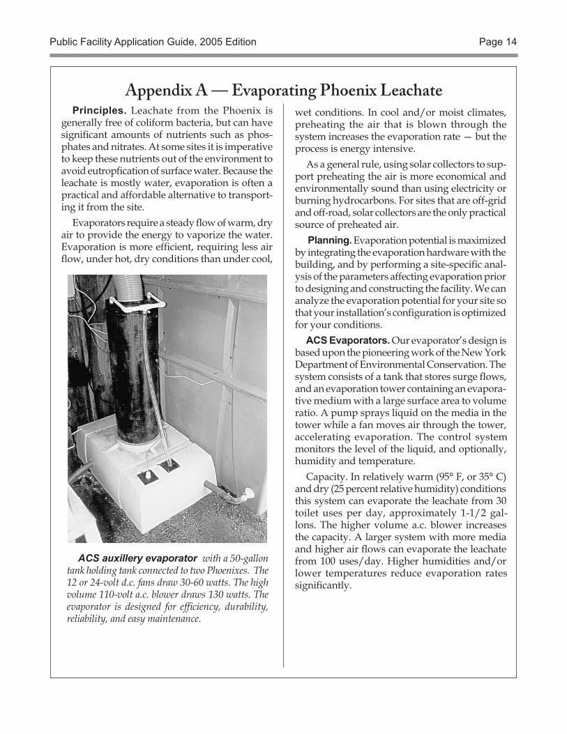
ACS auxillery evaporator with a 50-gallon tank holding tank connected to two Phoenixes. The 12 or 24-volt d.c. fans draw 30-60 watts. The high volume 110-volt a.c. blower draws 130 watts. The evaporator is designed for efficiency, durability, reliability, and easy maintenance.
Principles. Leachate from the Phoenix is generally free of coliform bacteria, but can have significant amounts of nutrients such as phos-phates and nitrates. At some sites it is imperative to keep these nutrients out of the environment to avoid eutropfication of surface water. Because the leachate is mostly water, evaporation is often a practical and affordable alternative to transport-ing it from the site.
Evaporators require a steady flow of warm, dry air to provide the energy to vaporize the water. Evaporation is more efficient, requiring less air flow, under hot, dry conditions than under cool,
wet conditions. In cool and/or moist climates, preheating the air that is blown through the system increases the evaporation rate — but the process is energy intensive.
As a general rule, using solar collectors to sup-port preheating the air is more economical and environmentally sound than using electricity or burning hydrocarbons. For sites that are off-grid and off-road, solar collectors are the only practical source of preheated air.
Planning. Evaporation potential is maximized by integrating the evaporation hardware with the building, and by performing a site-specific anal-ysis of the parameters affecting evaporation prior to designing and constructing the facility. We can analyze the evaporation potential for your site so that your installation’s configuration is optimized for your conditions.
ACS Evaporators. Our evaporator’s design is based upon the pioneering work of the New York Department of Environmental Conservation. The system consists of a tank that stores surge flows, and an evaporation tower containing an evapora-tive medium with a large surface area to volume ratio. A pump sprays liquid on the media in the tower while a fan moves air through the tower, accelerating evaporation. The control system monitors the level of the liquid, and optionally, humidity and temperature.
Capacity. In relatively warm (95° F, or 35° C) and dry (25 percent relative humidity) conditions this system can evaporate the leachate from 30 toilet uses per day, approximately 1-1/2 gal-lons. The higher volume a.c. blower increases the capacity. A larger system with more media and higher air flows can evaporate the leachate from 100 uses/day. Higher humidities and/or lower temperatures reduce evaporation rates significantly.
Public Facility Application Guide, 2005 Edition Page 15
Appendix B — Phoenix Electrical Loads & PhotovoltaicsOff grid qualified. The Phoenix has extremely low elec-
trical requirements, and thus is ideal for off-the-utility-grid installations. This is by design.
Typical loads. The Phoenix’s 12-volt d.c., five-watt ventilation fan nominally consumes 120 watt hours each
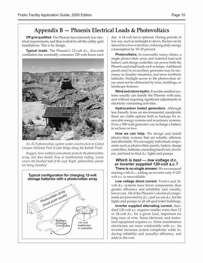
An ACS photovoltaic system under construction in Grand Canyon National Park (Cedar Ridge along the Kaibab Trail).
Rugged, twin-walled Lexan plastic protects the photovoltaic array, and does double duty as weatherproof roofing. Lexan covers the finished half of the roof. Right, photovoltaic panels are being installed
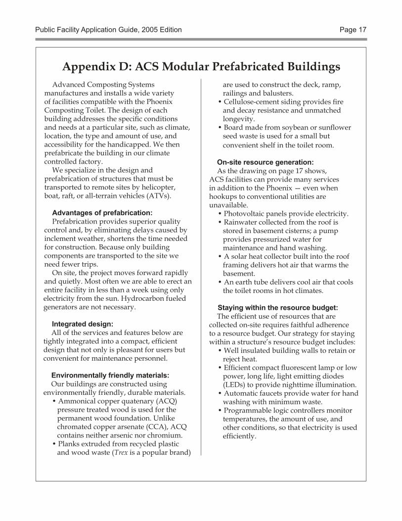
12-voltbatteriesin parallel
Battery Charge Controller
Photovoltaic array
(must point south)
Typical configuration for charging 12-voltstorage batteries with a photovoltaic array
Which is best — low voltage d.c.or inverter supplied 120-volt a.c.?There is no single answer. We recommend
starting with d.c., adding an inverter only if 120-volt a.c. is unavoidable.
Low voltage direct current. Twelve and 24-volt d.c. systems have fewer components, thus greater efficiency and reliability and, usually, lower cost. All of the Phoenix’s electrical compo-nents are powered by d.c., and we use d.c. for the lights and pumps in all off-grid toilet buildings.
Inverter supplied alternating current. Stan-dard 120-volt a.c. requires smaller wires than 12 or 24-volt d.c. for a given load, important for long runs of wire. Some electronic and motor-ized equipment requires a.c. Some maintenance electricians are more comfortable with a.c. An inverter increases system complexity while re-ducing reliability and (usually) efficiency, and adds to the cost.
day. A 24-volt fan is optional. During periods of low use, such as midnight to dawn, the fan can be slowed to a two-watt draw, reducing daily energy consumption by 10–20 percent.
Photovoltaics. In reasonably sunny climes, a single photovoltaic array and matched lead-acid battery and charge controller can power both the Phoenix and small loads such as lamps. Additional panels and/or an auxiliary generator may be nec-essary in cloudier situations, and more northerly latitudes. Sunlight access to the photovoltaic ar-ray must not be obstructed by trees, buildings, or landscape features.
Wind and micro-hydro. Even the smallest sys-tems usually can handle the Phoenix with ease, and without requiring significant adjustments in electricity consuming activities.
Hydrocarbon fueled generators. Although less friendly from an environmental standpoint, these are viable options both as backups for re-newable energy systems and as primary systems. Even a 500-watt generator can recharge a battery in an hour or two.
How we can help. We design and install photovoltaic systems that are reliable, efficient, and affordable. We can supply individual compo-nents such as photovoltaic panels, battery charge controllers, batteries, mounting hardware, invert-ers, and hard-to-find d.c. lights and pumps.
Public Facility Application Guide, 2005 Edition Page 16
To design the new system, four major issues were addressed. The park needed to:
1. Reduce electric loads as much as possible.
2. Minimize operational and maintenance costs.
3. Meet architectural con-cerns.4. Prevent potential van-dalism.
Creative Solutions.
Catalytic propane heaters (12V ignition) replace electric heaters, 3M window tinting re-duces heat buildup on hot days, high efficiency light fixtures went up, and 12-volt circuits minimize loss associated with voltage in-verters.
Batteries are easier to service because they are mounted on a simple cart and two [charge] controllers provide MSX-64 photovoltaic redundancy (essential to any well heeled PV system).
Placing the panels on a 45-foot pole 300 feet from the entrance station solved architectural and vandalism concerns. The bat-teries and controllers are clev-erly hidden in the old generator house, some 150 feet from the entrance station. To the untrained eye, it appears the fee station now has commercial power.
The project costs ($9,500.00) were shared by Crater Lake na-tional Park, the Columbia/Cascades SSO, and Sandia Labs.
Big savings.
The photovoltaic system has been in place for 1.5 years. It is very reliable and operational costs are minimal. In fact, sav-ings realized by the photovoltaic systems will pay for the im-provements in just 9.5 years. Factoring inflationary increases, the payback period decreases dramatically. The biggest savings are for the environment because Crater Lake will NOT use some 5.000 gallons of gasoline and 300
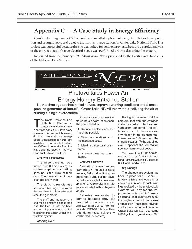
Photovoltaics Power AnEnergy Hungry Entrance Station
New technology soothes rattled nerves, improves working conditions and silences gasoline generator at beautiful Crater Lake NP. All this without polluting the air or burning a single hydrocarbon.
The North Entrance Fee Collection Station at Crater Lake National Park
is only open about 100 days every summer. This does not, however, diminish the station’s energy needs. Commercial power is [not] available to this remote location. An 8000-watt generator filled the bill, powering electric heaters, large light fixtures and fans.
Life with a generator.
The thirsty generator was fueled 2 or 3 times a day by station employees shuttling gasoline in the trunk of their cars. The generator’s oil was changed every week.
The station’s remoteness had one advantage: it allowed thieves time to dismantle and steal the generator.
The staff and management had mixed emotions about their loss. The theft, in truth, did have a silver lining: managers decided to operate the station with a pho-tovoltaic system.
Starting over
Careful planning pays. ACS designed and installed a photovoltaic system that reduced pollu-tion and brought peace and quiet to the north entrance station for Crater Lake National Park. This project was successful because the site was suited for solar energy, and because a careful analysis of the entrance station’s true electrical needs was performed prior to designing the system.
Reprinted from the January, 1996, Maintenance News, published by the Pacific-West field area of the National Park Service.
Appendix C — A Case Study in Energy Efficiency
Public Facility Application Guide, 2005 Edition Page 17
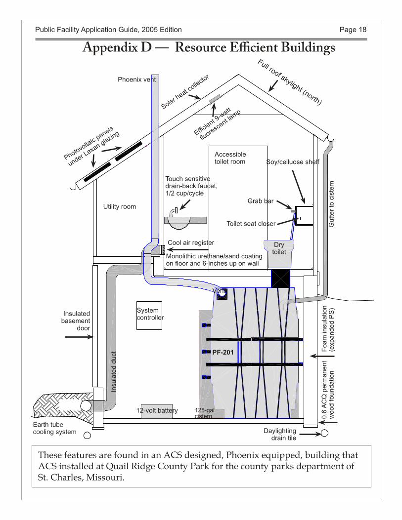
Advanced Composting Systems manufactures and installs a wide variety of facilities compatible with the Phoenix Composting Toilet. The design of each building addresses the specific conditions and needs at a particular site, such as climate, location, the type and amount of use, and accessibility for the handicapped. We then prefabricate the building in our climate controlled factory.
We specialize in the design and prefabrication of structures that must be transported to remote sites by helicopter, boat, raft, or all-terrain vehicles (ATVs).
Advantages of prefabrication:Prefabrication provides superior quality
control and, by eliminating delays caused by inclement weather, shortens the time needed for construction. Because only building components are transported to the site we need fewer trips.
On site, the project moves forward rapidly and quietly. Most often we are able to erect an entire facility in less than a week using only electricity from the sun. Hydrocarbon fueled generators are not necessary.
Integrated design:All of the services and features below are
tightly integrated into a compact, efficient design that not only is pleasant for users but convenient for maintenance personnel.
Environmentally friendly materials:Our buildings are constructed using
environmentally friendly, durable materials.• Ammonical copper quatenary (ACQ)
pressure treated wood is used for the permanent wood foundation. Unlike chromated copper arsenate (CCA), ACQ contains neither arsenic nor chromium.
• Planks extruded from recycled plastic and wood waste (Trex is a popular brand)
are used to construct the deck, ramp, railings and balusters.
• Cellulose-cement siding provides fire and decay resistance and unmatched longevity.
• Board made from soybean or sunflower seed waste is used for a small but convenient shelf in the toilet room.
On-site resource generation:As the drawing on page 17 shows,
ACS facilities can provide many services in addition to the Phoenix — even when hookups to conventional utilities are unavailable.
• Photovoltaic panels provide electricity.• Rainwater collected from the roof is
stored in basement cisterns; a pump provides pressurized water for maintenance and hand washing.
• A solar heat collector built into the roof framing delivers hot air that warms the basement.
• An earth tube delivers cool air that cools the toilet rooms in hot climates.
Staying within the resource budget:The efficient use of resources that are
collected on-site requires faithful adherence to a resource budget. Our strategy for staying within a structure’s resource budget includes:
• Well insulated building walls to retain or reject heat.
• Efficient compact fluorescent lamp or low power, long life, light emitting diodes (LEDs) to provide nighttime illumination.
• Automatic faucets provide water for hand washing with minimum waste.
• Programmable logic controllers monitor temperatures, the amount of use, and other conditions, so that electricity is used efficiently.
Appendix D: ACS Modular Prefabricated Buildings
Public Facility Application Guide, 2005 Edition Page 18
Photovoltaic panels
under Lexan glazing
Phoenix vent
Earth tubecooling system
Solar heat collecto
r
Utility room
Touch sensitive drain-back faucet, 1/2 cup/cycle
Drytoilet
Vent
Cool air register
Accessibletoilet room
Full roof skylight (north)
Insulatedbasement
door
Monolithic urethane/sand coating on floor and 6-inches up on wall
Soy/celluose shelf
Toilet seat closer Gut
ter t
o ci
ster
nFo
am in
sula
tion
(exp
ande
d P
S)
0.6
AC
Q p
erm
anen
tw
ood
foun
datio
n
Insu
late
d du
ct
Daylightingdrain tile
12-volt battery
Systemcontroller
125-galcistern
Grab bar
PF-201
Efficient 9-watt
fluoresce
nt lamp
These features are found in an ACS designed, Phoenix equipped, building that ACS installed at Quail Ridge County Park for the county parks department of St. Charles, Missouri.
Appendix D — Resource Efficient Buildings
Appendix E: Phoenix SpecificationsGeneral. The Phoenix Public Facility Package
shall be supplied as a complete system except for the exterior vent pipe and wood shavings starter bed. The package shall contain all of the components, hardware and instructions necessary for assembling, installing, and operating the system.
The Phoenix Composting Tank shall be man-ufactured with a 1/4" thick rotationally molded, polyethylene exterior shell and a chemically bonded, 5/8" thick foamed polyethylene internal insulation layer. An internally overlapping, gasketed flange shall assure a leak proof joint between tank sections. The system design, dimensions and geometry shall assure that: the entire top of the compost pile is ac-cessible for maintenance; compost travels through the tank in a First-In-First-Out path; all of the oldest material beneath the bottom tines can be removed with a conventional shovel without contamination with fresh waste.
Access Doors shall have a pultruded fiberglass frame, polyethylene interior and exterior faces sand-wiching 1" insulation and an anodized aluminum handle. The Access Doors shall fit into extruded alu-minum frames sealed to the Phoenix Tank and shall be totally removable to facilitate maintenance.
Baffles shall be located along the interior of both sides of the Phoenix Tank to provide aeration of the compost pile while and not interfering with compost movement.
A Porous Floor located above the bottom of the Phoenix Tank shall separate leachate from compost. A stable, aerated medium located beneath this floor shall provide secondary treatment for liquid before it drains from the tank.
Rotatable tines shall assist in mixing the top of the compost pile and control the movement of finished compost to the access area during compost removal. Tine shafts installed in the tank bottom and midsection shall be perforated to provide additional aeration to the interior of the compost pile. An op-tional air injection system shall control pressurized air delivery to the tine shafts based on toilet use. All components of the tine shaft and bearing assembly shall be innately corrosion proof, fiberglass, UHMW polyethylene, and 316 stainless steel.
The Vent system shall consist of a fan assembly; 5' of wire-reinforced, flexible, vinyl interior vent hose; neoprene flashing to fit roof pitches from flat to 12/12; stainless steel screened vent cap and all fasteners required for installation.
The Fan assembly shall contain a 5-watt, 12 or 24-volt dc, brushless fan, encapsulated for corrosion resistance so that it will run under water, and a tem-perature sensor and condensate drain. The fan shall be capable of being powered with a plug-in 120-volt ac power supply or an optional photovoltaic system. To conserve electricity and heat, an optional fan speed controller shall control the ventilation rate based on the time of day, occupancy and battery state of charge.
A Liquid spray system shall periodically spray water or leachate on the compost pile to inoculate fresh material with organisms that promote the de-composition process, and to keep the entire compost pile moist.
The Toilet shall be manufactured from white cross-linked polyethylene and ABS. It shall be 14" tall (barrier free, 18" tall) and include a black tapered polyethylene liner, 3' of 12" diameter polyethylene chute, tank connector and toilet seat which seals when shut.
All Fasteners shall be corrosion proof stainless steel, nylon, or fiberglass.
Maintenance tools shall include a rake capable of reaching to the back of the tank, a tray for collecting finished compost, a reacher for removing trash and a door opening counter to tally uses.
Installation shall be performed by an ACS trained installer and certified by an authorized representative of Advanced Composting Systems to assure proper installation and to validate the warranty.
Substitution of an “or equal” system shall require that an independent engineering firm verify, through scientifically documented engineering analyses, dem-onstrations and tests, to the satisfaction of the custom-er, that the substituted system is equal to the Phoe-nix in the following specific areas: Composting tank material longevity, strength, service temperature, corrosion resistance and tank wall thermal conduc-tivity; Tine shaft and bearing material strength, wear resistance and corrosion resistance; First-in, First-out compost movement, ease of compost removal and tank volume and utilization factor; compost aer-ation root-mean-square path length; mean liquid path length and retention time; ventilation rate, fan speed control and energy consumption; ventilation fan corrosion resistance and longevity; vent system corrosion resistance and leak resistance.
Public Facility Application Guide, 2005 Edition Page 20
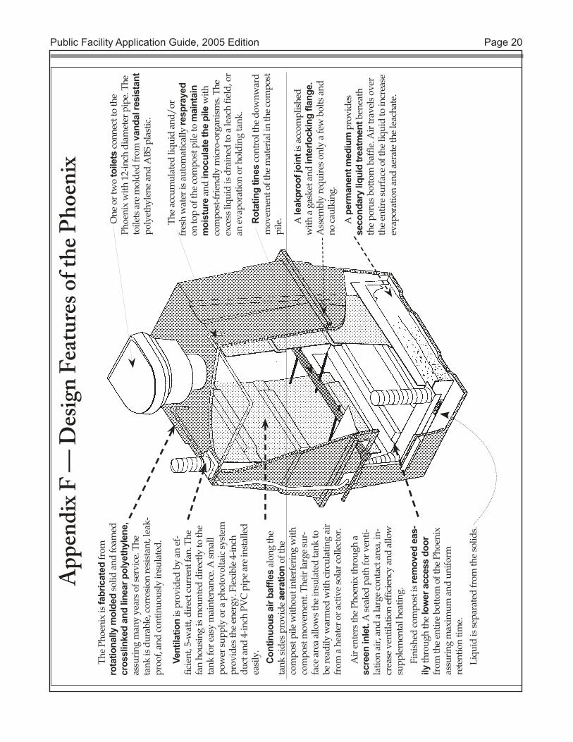
The
Phoe
nix
is fa
bric
ated
from
ro
tatio
nally
mol
ded
solid
and
foam
ed
cros
slin
ked
and
linea
r pol
yeth
ylen
e,
assu
ring
man
y ye
ars o
f ser
vice
. The
ta
nk is
dur
able
, cor
rosio
n re
sista
nt, l
eak-
proo
f, an
d co
ntin
uous
ly in
sula
ted.
Fini
shed
com
post
is re
mov
ed e
as-
ily th
roug
h th
e lo
wer
acc
ess
door
fr
om th
e en
tire
botto
m o
f the
Pho
enix
as
surin
g m
axim
um a
nd u
nifo
rm
rete
ntio
n tim
e.
Air
ente
rs th
e Ph
oeni
x th
roug
h a
scre
en in
let.
A se
aled
pat
h fo
r ven
ti-la
tion
air,
and
a la
rge
cont
act a
rea,
in-
crea
se v
entil
atio
n ef
ficie
ncy
and
allo
w
supp
lem
enta
l hea
ting.
Con
tinuo
us a
ir ba
ffles
alo
ng th
e ta
nk si
des p
rovi
de a
erat
ion
of th
e co
mpo
st p
ile w
ithou
t int
erfe
ring
with
co
mpo
st m
ovem
ent.
Thei
r lar
ge su
r-fa
ce a
rea
allo
ws t
he in
sula
ted
tank
to
be re
adily
war
med
with
circ
ulat
ing
air
from
a h
eate
r or a
ctiv
e so
lar c
olle
ctor
.
Vent
ilatio
n is
prov
ided
by
an e
f-fic
ient
, 5-w
att,
dire
ct cu
rren
t fan
. The
fa
n ho
usin
g is
mou
nted
dire
ctly
to th
e ta
nk fo
r eas
y m
aint
enan
ce. A
smal
l po
wer
supp
ly o
r a p
hoto
volta
ic sy
stem
pr
ovid
es th
e en
ergy
. Fle
xibl
e 4-
inch
du
ct a
nd 4
-inch
PV
C p
ipe
are
inst
alle
d ea
sily.
Liqu
id is
sepa
rate
d fr
om th
e so
lids.
One
or t
wo
toile
ts co
nnec
t to
the
Phoe
nix
with
12-
inch
dia
met
er p
ipe.
The
to
ilets
are
mol
ded
from
van
dal r
esis
tant
po
lyet
hyle
ne a
nd A
BS p
last
ic.
The
accu
mul
ated
liqu
id a
nd/o
r fr
esh
wat
er is
aut
omat
ical
ly re
spra
yed
on to
p of
the
com
post
pile
to m
aint
ain
moi
stur
e an
d in
ocul
ate
the
pile
with
co
mpo
st-fr
iend
ly m
icro
-org
anism
s. Th
e ex
cess
liqu
id is
dra
ined
to a
leac
h fie
ld, o
r an
eva
pora
tion
or h
oldi
ng ta
nk.
Rot
atin
g tin
es co
ntro
l the
dow
nwar
d m
ovem
ent o
f the
mat
eria
l in
the
com
post
pi
le. A le
akpr
oof j
oint
is a
ccom
plish
ed
with
a g
aske
t and
inte
rlock
ing
flang
e.
Ass
embl
y re
quire
s onl
y a
few
bol
ts a
nd
no ca
ulki
ng.
A p
erm
anen
t med
ium
pro
vide
s se
cond
ary
liqui
d tre
atm
ent b
enea
th
the
poru
s bot
tom
baf
fle. A
ir tra
vels
over
th
e en
tire
surf
ace
of th
e liq
uid
to in
crea
se
evap
orat
ion
and
aera
te th
e le
acha
te.
App
endi
x F —
Des
ign
Feat
ures
of t
he P
hoen
ix