using pneumatic fracturing for in-situ remediation of contaminated sites
TRANSCRIPT
t
Using Pneumatic Fracturing for In-Situ Remediation of Contaminated Sites
John R. Schuring Paul C. Chan Thomas M. Boland
Jobn R Scburlng is Assodate Aofessor of CiuU Engineering New Jersey Institute of Tecbnobgy. Pa& C Cban i s I+yfesso+ of Civil Engineerin& New Jersey Institute of Tecbnobgy. Tb0tna.s M. Boltand is a JeId engineer witb tbe center fo’Envimmenta1 Engineering and Science, New Jersey Institute of T ~ ~ g Y .
Pneumatic fracturing is an innovative lechnology enhancing the removal and treatment of contaminants in moderate-to-low permeability formations. 72xe main advantages are a reduction in treatment time and the extension of available in-situ technologies to more difacult geologic conditions. Pneumatic fracturing has been successfully demonstrated in the fleld at a number of contaminated sites and in a variety of geologic formations. The technology is now commercially available and is being incorporated into site cleanups. i%is article provides an overview of the pneumatic fracturing technology, beginning with a general description of the concept and apparatus. Next, key technological considerations will be d&cwed including fracture initiation, fracture orientation, fractureflow, and treatable soils and contaminants. 7%ree case studies are presented describing dafwent applications of pneumalic fracturing. The article concludes with a discussion of cost benefits of [he technology.
In selecting technologies to remediate contaminated soil and ground water, the in-situ approach-treating the contaminants in place without excavating and disturbing-is the preferred approach. In most cases, the in-situ approach is the most economical altcrnative, and a number of technologies have emerged over the last decade showing varying degrees of success. The major obstacle of in-situ remediation is the permeability of the geologic formation. If the site contains fine-grained soils, such as silts or clays, or dense bedrock, such as shale or siltstone, in-situ tcchnologies are nor effective. The hydraulic conductivity limit below which most in-situ technologies are not normally applicable is 1 x
To overcome the inherent difficulties of remediating fine-grained soils and dense bedrock, a process known as ’pneumatic fracturing” was developed at the Hazardous Substance Management Research Center (HSMRC) located at the New Jersey Institute of Technology (NJIT) in Newark. The process may be generally described as injecting air (or another gas) into a contaminated geologic formation at sufficient pressure and flow rate so that artificial fractures are created. Once established, the fractures increase the permeability of the formation, thereby making contaminant removal or treatment more efficient. Pneumatic fracturing is similar in concept to the hydraulic fracturing tech- niques’ used in the petroleum and watcr-well industry to cnhance product
cm/sec.
CCC 1051-5658/95/050277-14 0 1995 John Wiley & Sons, Inc.
77
JOHN R S~HUIUNG PAUL C. CHAN THOMAS M. BOLAND
The principal objectives of pneumatic fracturing are reducing keatment time and extending available technologies to more dificult georogic conditions.
recovery, except pneumatic fracturing uses air as an injection fluid instead of water. Pneumatic injection has the advantage of more rapid fracture propa- gation, and avoids i n d u c i n g additional liquid into the subsurface which can spread contaminants, especially in the vadose zone, Pneumatic fracturing also provides beneficial aeration or sp-g of the formation during pneumatic injection.
Initial development of the pneumatic fracturing process began with laboratory bench scale testing and analytical modeling at HSMRC/NJIT.2 The first industrial site demonstration of pneumatic fracturing was con- ducted in 1990 in Richmond, Virginia.3 Since that time, development of the process has continued, including field pilot testing at more than 15 different sites in a variety of geologic conditions, including a U.S. EPA Superfund Innovative Technology Evaluation (SITE) Demonstration Program at a contaminated industrial site in New Jersey? Pneumatic fracturing is now available commercially through Accutech Remedial Systems of Keyport, New Jersey, and is being applied to cleanups. Pneumatic fracturing is a patented process, and the assignee is the HSMKC/NJIT.
GENERAL TECHNOLOGY DESCRIPTION The principal objectives of pneumatic fracturing are reducing treat-
ment time and extending available technologies to more difficult geologic conditions. Pneumatic fracturing is an enhancement process designed to be integrated with primary in-situ treatment technologies such as vapor extraction, bioremediation, thermal treatment, and pump and treat. The technology has been applied to a range of hydrogeologic conditions including vadose zones, perched water zones, and Sdturdted zones.
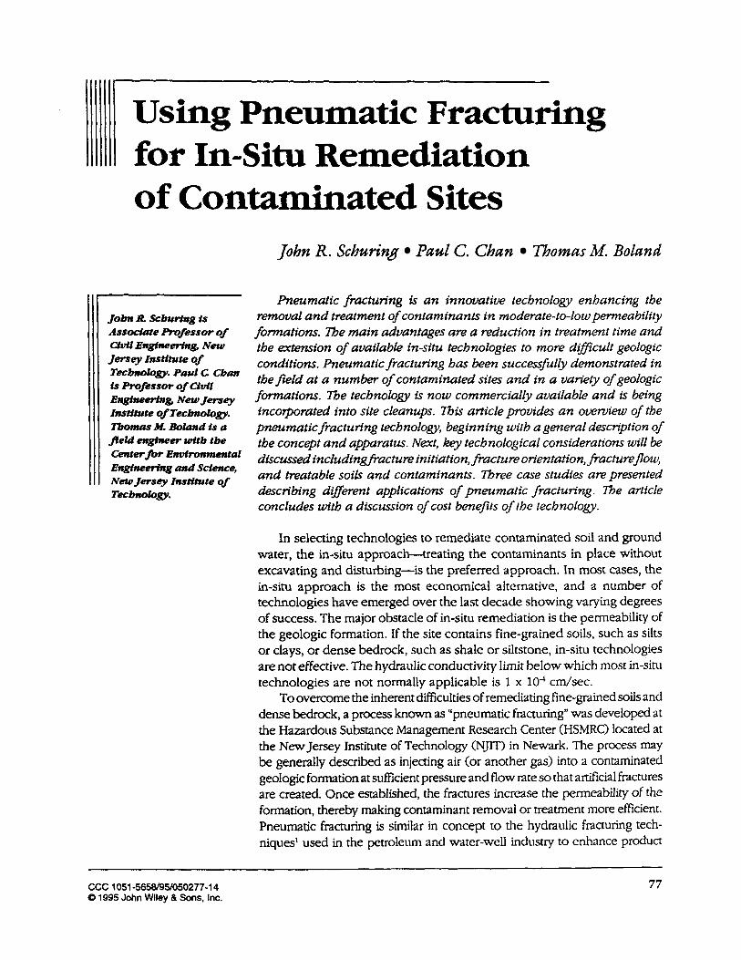
The effects of pneumatic fracturing on two different geologic formations are shown conceptually in Exhibit 1. For formations containing significant amounts of silt and clay, the process creates new convective pathways in the formation that increase permeability and shorten diffusive distances (Exhibit 1 (a)). In sedimentary rock formations such as sandstone and shale, the process can dilate and extend existing discontinuities, increasing permeability and improving interconnection (Exhibit 1 (b)). Pneuiiiatic fracturing can also be applied in more permeable formations, such as sand, for the purpose of rapid aeration and sparging. The system can also deliver granular or liquid supplements, such as nutrients, innoculum, and reactive media, directly into the subsurface to enhance in-sin1 technologies such as bioremediation and thermal treatment.
The actual process of pneumatic fracturing is relatively rapid, and good field productivity is achievable. An individual pneumatic injection is accomplished by: (1) positioning a proprietary device known as an “HQ Injector“ in the fracture well sealing off a discrete one-to-two-foot interval; (2) applying pressurized air for approximately 30 seconds; and (3) repositioning the HQ Injector to the next elevation and repeating the procedure. A typical cycle takes between 15 and 30 minutes, depending on the amount of time required to move the injector vertically within the same hole, and horizontally from hole to hole. A production rate of 20 fractures per day is considered attainable with one apparatus, although
78 REMBDIATION/SPRING 1995
USING PNEUMATIC FRACIXWNG FOR I N - S ~ REMEDIATION OF CO~AIKINATED S m
~- ~~~ ~~ ~~~ ~~~
Exhibit 1. Pneumatic Fracturing Concept.
BEFOAE FRACTURE WER FRACTURE (Dillusion Controlled) (Convedion & Diffusion Controlled)
A . _ . , . ' . . . . . . ) . . . . .
see Detail "A'
BEFORE FRACTURE AFTER FRACTURE
OETNL 'A' DETAIL "A" VAPOR MOVEMENT IN SOIL MICROSTRUCTURE EFFECT OF FRACTURING ON ROCK DISCONTINUITIES
(a) Fine-Grained Soils (b) Rock Formations
pilot studies typically proceed at a slower rate to allow time for more precise measurements.
Pneumatic fracturing can be applied as pretreatment to increase formation permeability during the initial stage of a cleanup, or it can be retrofitted to an ongoing remediation. Common applications include: (1) prefracturing of new extnctiodinjection wells during their construction; (2) stimulating flow in existing, low-producing wells; and (3) improving uniformity and altering direction of formation flow (ground water or air). In some cases, it may be desirable to refracture a formation more than once, depending on formation geology and project duration. Repeated injections may also be appropriate at bioremediation sites for periodic replenishment of biological supplements into the formation under treatment.
KEY TECHNOLOGY CONSIDERATIONS FOR SITE APPLICATION In order to apply pneumatic fracturing effectively, understanding some
key principles of the technology is helpful. This section discusses how pneumatic fractures are created, as well as the behavior of geologic formations after fracturing. It also provides guidelines on the types of geologic materials and contaminants treatable.
REMEDLATION/SPRING 1995 79
Jow R scRUapJ0 PAUL C. CHAN THOMAS M. BOW
When thepneumatic iqjection is terminated, closure of the Factures is partial since nioat formations exhibit a behavior known as "sezf-propping. "
Pneumatic Fracture Mtiation Fractures can be formed in geologic formations if air is injected at a
pressure exceeding the natural strength, as well as the in-situ stresses present. The air must also be injected at a flow rate exceeding the natural permeability of the formation so that sufficient "back" pressure can be developed. If these two conditions are met, the geologic medium will fail, and artificial fractures will radiate from the injection point. The amount of pressure required to initiate pneumatic fractures is a function of the cohesive strength of the formation, as well as the thickness of overburden. Typical pressure values for clay soil and shale bedrock at a depth of 20 feet are 75 psi and 200 psi, respectively.
Pneumatic Fracture Orientation The orientation of the pneumatic fractures can be predicted by
considering the direction of the major principal geostatic stresses present in the formation. In most formations, horizontal fractures will predominate, owing to natural overconsolidation from past geologic events such as overburden stress relief, dessication, and tectonic forces. The tendency towards horizontal orientation is further accentuated in stmtified forma- tions because of natural weaknesses along the bedding planes. Some upward inclination of pneumatic fractures has been observed in shallow, recent fills. In some cases, these inclined fractures have intersected or "daylighted" the ground surface.
Fractured Media Flow After a geologic formation has been pneumatically fractured, the ability
to treat and/or remove contaminants will depend on the flow and transport characteristics of the artificially fractured medium. When the pneumatic injection is terminated, closure of the fr-ctures is partial since most formations exhibit a behavior known as "self-propping." This is attributed to the irregularities present along the fracture plane, as well as the formation shifting taking place during injection. The open, self-propped fractures resulting from pneumatic injection are capable of transmitting significant amounts of fluid. The fluid mechanics principle applying to flow in open pneumatic fractures is known as the "cubic law."5 Brittle geologic materials will self-prop better than more ductile geologic materials. Some formations, such as softer, sensitive clays, will not exhibit self-propping behavior. Injecting a granular propping agent into these formations may be desirable. For some applications, injecting granular or liquid media for additional purposes such as biological supplemenration or chemical reduction is also advantageous.
T y p e s of Treatable SoLVRock The texture and structure of a geologic formation are important
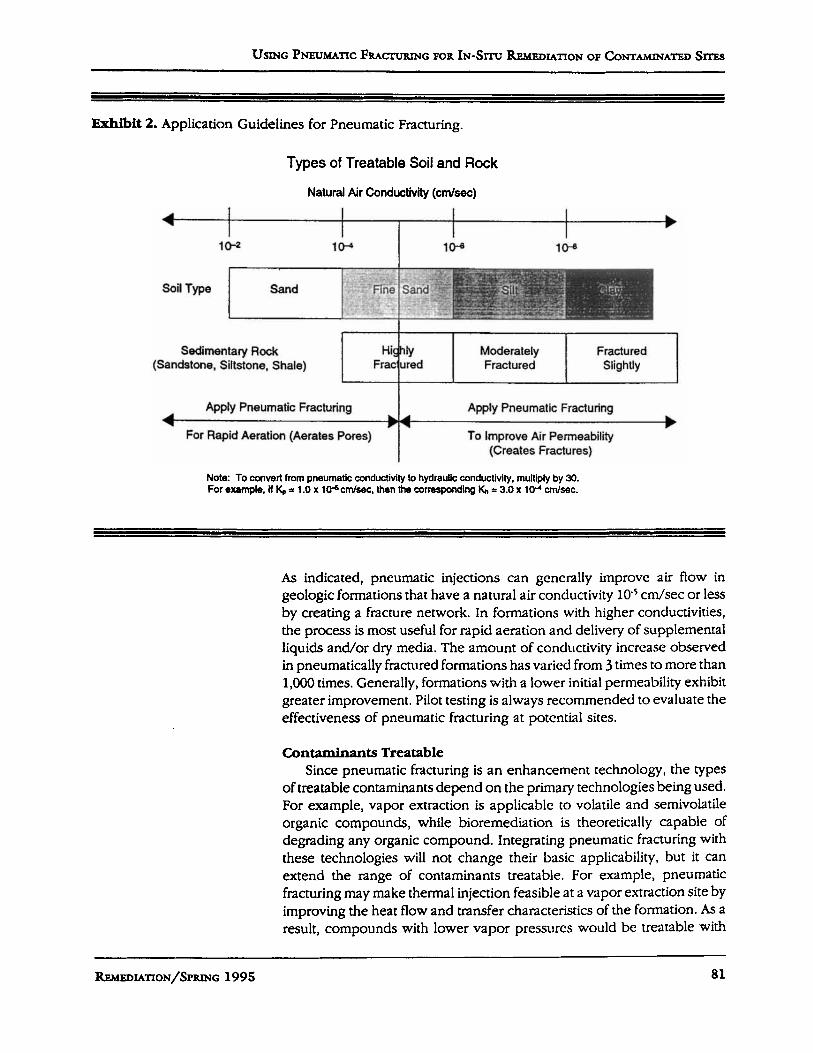
considerations when applying pneumatic fracturing. The technology has been successfully demonstrated in a number of moderate-to-low perme- ability formations to date. Based on the results of these tests, guidelines for potential application have been developed and are shown in Exhibit 2.
80 REMEDIATION/~PRING 1995
USING PNEUMATIC FRACL-URING FOR IN-SXTU REMEDIATION OF CONTAMINATED SITES
10-2 lo"
~
Exhibit 2. Application Guidelines for Pneumatic Fracturing.
1o-e 1W
Sedimentary Rock (Sandstone, Siltstone, Shale)
HiShly Moderately Fractured Frac ured Fractured Slightly
As indicated, pneumatic injections can generally improve air flow in geologic formations that have a natural air conductivity 10r c d s e c or less by creating a fracture network. In formations with higher conductivities, the process is most useful for rapid aeration and delivery of supplemental liquids and/or dry media. The amount of conductivity increase observed in pneumatically fractured formations has varied from 3 times to more than 1,000 times. Generally, formations with a lower initial pernieability exhibit greater improvement. Pilot testing is always recommended to evaluate the effectiveness of pneumatic fracturing at potential sites.
Apply Pneumatic Fracturing
For Rapid Aeration (Aerates Pores) 4
Contaminants Treatable Since pneumatic fracturing is an enhancement technoloby, the types
of treatable contaminants depend on the primary technologies being used. For example, vapor extraction is applicable to volatile and semivolatile organic compounds, while bioremediation is theoretically capable of degrading any organic compound. Integrating pneumatic fracturing with these technologies will not change their basic applicability, but it can extend the range of contaminants treatable. For example, pneumatic fracturing may make thermal injection feasible at a vapor extraction site by improving the heat flow and transfer characteristics of the formation. As a result, compounds with lower vapor pressures would be treatable with
Apply Pneumatic Fracturing
To Improve Air Permeability (Creates Fractures)
b t -b
REMEDIATION/SPIUNG 1995 81
JOHN R ~ ~ ~ U R I N G PAUL C. C h w THOMAS M. BOW
Geotechnical
performed to WdY8e8 8hOUId be
establish tokrabte movements for a particular pr~ject, and the fracture i+ctionn designed appropriately.
vapor extraction. Similarly, the ability to inject biological solutions contain- ing microbes and nutrients directly into a geologic formation will increase the number of organic compounds treatable with bioremediation.
Applicability near Structures and Utilities Pneumatic fracture injections cause deformation and heaving of the
geologic medium under treatment. Peak ground surface heave observed during the actual injection event (which lasts about 20 seconds) have ranged from 1/8 of an inch to 2 inches. These values are typically observed at the injection point, and heave magnitude tapers to zero with increasing radius. The "residual" heave recorded after termination of the injection typically ranges between 10 percent and 20 percent of the injection heave. The effects of pneumatic injections on nearby structures and utilities depend on the type of construction and the magnitude of ground deformation. Geotechnical analyses should be performed to establish tolerable movements for a particular project, and the fracture injections designed appropriately. It is noted that experience with fracturing in the vicinity of structures and utilities is still limited, so caution is recommended when fracturing in close proximity to critical Facilities.
CASE S"'UDm OF PNEUMATIC F€UCTURING
Case One: Enhancement of Vapor Extraction in Clay StteDescription. The site of the first case study is an abandoned tank
farm located in Richmond, Virginia. It was underlaid by a stratum of stiff, overconsolidated clay entirely in the vadose zone. At the time of the field test, the steel VOC (volatile organic compound) storage tanks had been removed, leaving only a six-inch-thick concrete slab over the site. Soil samples from the vadose zone beneath the slab showed the two principal VOCs in the clay: methylene chloride (MeCI,) and l,l,l-trichloroethane (TO. The entry route of the VOCs appears-to have been leakage from sumps, and the areal extent was localized. VOC concentrations, as determined by headspace analysis of spoon samples and gas chromato- graph analysis of soil samples, ranged up to 8,500 ppm and 485 ppm, respectively .
FieIdOperation. After site characterization, a vapor extraction system was installed and briefly operated to establish baseline behavior against which the pneumatic fracturing injections could later be evaluated. During vapor extraction system operation, soil gas effluents were measured using a Perkin-Elmer ICAMS continuous-reading mass spectrometer. The next step was to pneumatically fracture the clay around the wells to increase formation permeability, and then to evaluate the effects on the VOC extraction system. Six fracture injections were made in two boreholes at a depth range of 6.8 to 10.7 feet below the slab surface. In addition, ground- surface heave measurements were made to assess fracture radius, and air communication with surrounding monitoring wells was recorded.
ResuZts: Baseline testing established that the VOC removal rate from the formation was very low. A typical VOC effluent curve observed during
82 WMBDIATION/SPRING 199 5
USXNG PNEUMATIC FRAC~VRTNG FOR I N - S ~ REMEDIATION OF CONTAMINATED S m
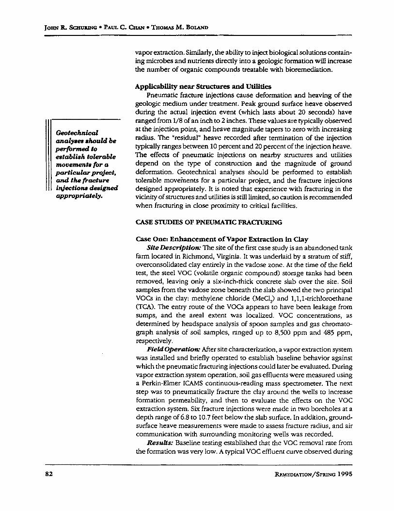
Exhibit 3. Case One: Effluent Behavior for Prefracture Restart Test.
20 1 VW-1 Vacuum: 27 in. Water
M&L, TCA I.. . . . I..
0
0 10 30 4 0 50 60 70
TIME (MIN)
system restart is shown in Exhibit 3. As indicated, MeCl, concentration peaked at 17 ppm after several minutes and reached a non2etectable level after 35 minutes. Typical TCA concentrdtions were significantly lower. These effluent restart curves display "diffusion controlled" behavior-soil gas extraction exceeded the rate VOCs could migrate to the well by advection. As a result, effluent levels were dmwn down every time the well was evacuated, even though the surrounding soil contained elevated VOC levels. This concentration behavior was consistent with the extremely low prefracture air flows measured from the extraction well of less than 0.00071 SCFM, the lower measurement limit. The low permeability of the formation was further confirmed by the inability to dctcct vacuum at the outlying monitoring wells.
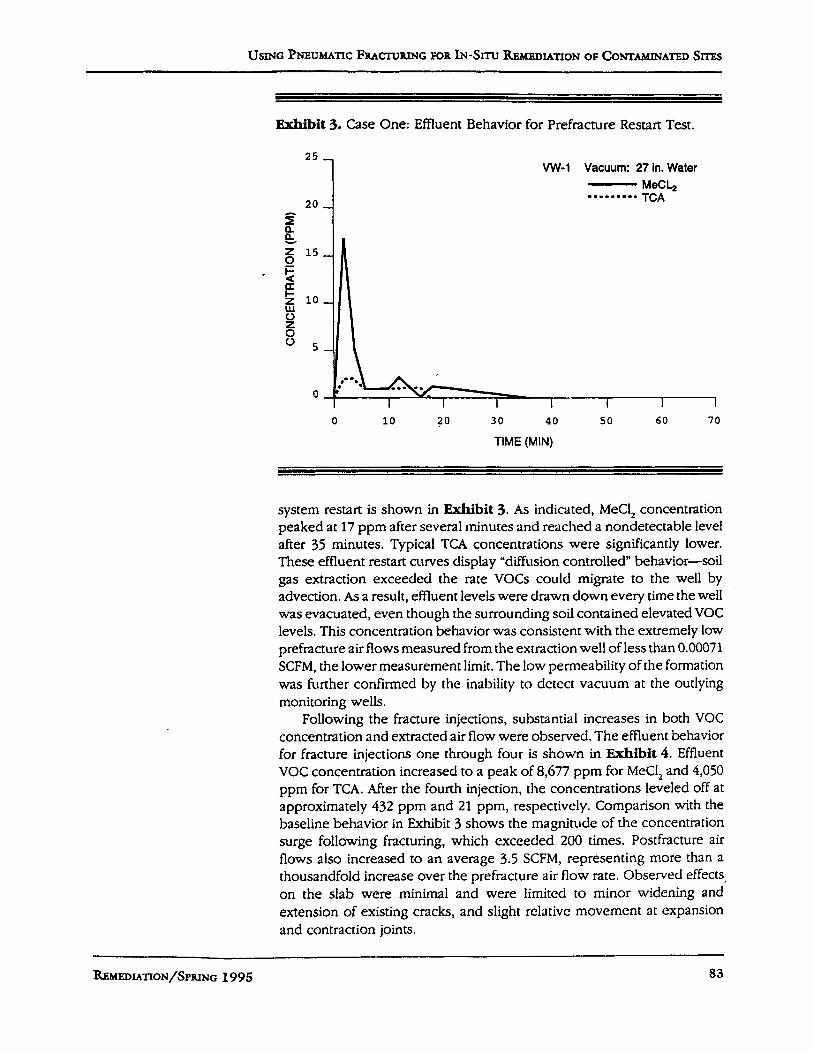
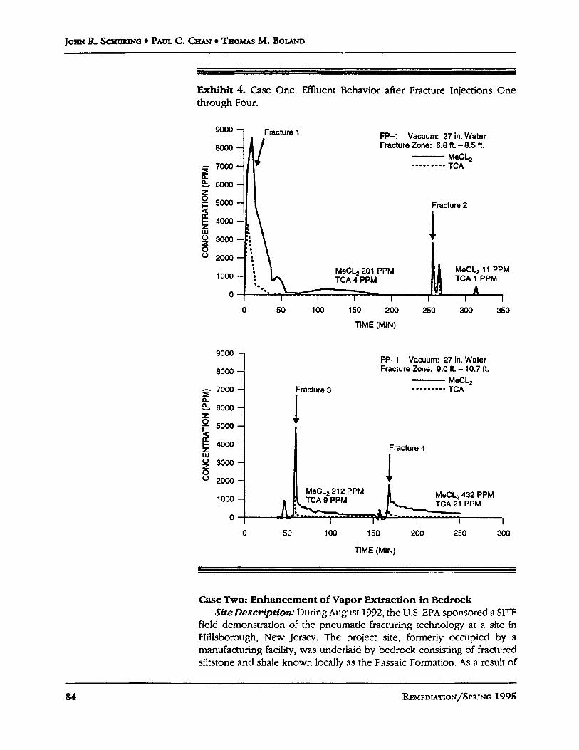
Following the fracture injections, substantial increases in both VOC concentration and extracted air flow were observed. The effluent behavior for fracture injections one through four is shown in Exhibit 4. Effluent VOC concentration increased to a peak of 8,677 ppm for MeCl, and 4,050 ppm for TCA. After the fourth injection, the concentrations leveled off at approximately 432 ppm and 21 ppm, respectively. Comparison with the baseline behavior in Exhibit 3 shows the magnitude of the concentration surge following fracturing, which exceeded 200 times. Postfracture air flows also increased to an average 3.5 SCFM, representing more than a thousandfold increase over the prefracture air flow rate. Observed effects, on the slab were minimal and were limited to minor widening and extension of existing cracks, and slight rclativc movement at expansion and contraction joints.
REMEDIATION/SPRING 1995 83
JOHN R SCSUBINC PAUL C. CHAN THOMAS M. BOLAND
go00 - 8000 -
g 7-- & 6000- z
5 5 50m: 4000
W y 3000-
8 2000-
lo00 - 0
Exhibit 4. Case One: Effluent Behavior after Fracture Injections One through Four.
FP-1 Vacuum: 27 in. Water Fracture Zone: 9.0 11. - 10.7 11. - MeCL,
TCA 1.. 1.---. Fracture 3
Fracture 4
I I
I
1000
0
FP-1 Vacuum: 27 in. Water Fracture Zone: 6.8 ft. - 8.5 ft.
MeCL, TCA . I.. I.. . .
Fracture 2
1 MeCb201 PPM MeCL, 11 PPM TCA 4 PPM TCA I PPM
A I I I 1
0 50 100 150 200 250 300 350
TIME (MIN)
Case Two: Enhancement of Vapor Extraction in Bedrock SifeDesCriptson* During August 1992, the U.S. EPA sponsored a SITE
field demonstration of the pneumatic fracturing technology at a site in Hillsborough, New Jersey. The project site, formerly occupied by a manufacturing facility, was underlaid by bedrock consisting of fractured siltstone and shale known locally as the Passaic Formation. As a result of
a4 REMBDIATION/SPRING 1995
Umc Pmumrxc FRACTURING FOR IN-SXTU REMEDIATION OF CONTAMINATED Sms
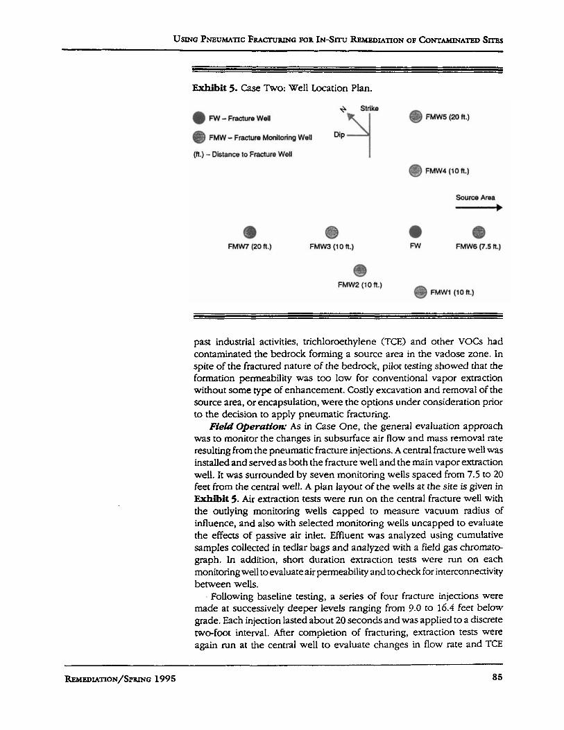
Exhibit 5. Case Two: Well Location Plan.
MI- Fracture Well
0 FMW - Fracture Monitoring Well
FMW5 (20 ft.)
(ft.) - Distance to Fracture Well i FMW4 (10 ft.)
FMW7 (20 ft.) FMW3 (loft.) 0
FMW6 (7.5ft.) 0 MI
FMW2 (loft.) FMWl (loft.)
past industrial activities, trichloroethylene (TCE) and other VOCs had contaminated the bedrock forming a source area in the vadose zone. In spite of the fractured nature of the bedrock, pilot testing showed that the formation permeability was too low for conventional vapor extraction without some type of enhancement. Costly excavation and removal of the source area, or encapsulation, were the options under consideration prior to the decision to apply pneumatic fracturing.
Field Operation= As in Case One, the general evaluation approach was to monitor the changes in subsurface air flow and mass removal rate resulting from the pneumatic fracture injections. A central fracture well was installed and served as both the fracture well and the main vapor extraction well. It was surrounded by seven monitoring wells spaced from 7.5 to 20 feet from the central well. A plan layout of the wells at the site is given in Exhibit 5. Air extraction tests were run on the central fracture well with the outlying monitoring wells capped to measure vacuum radius of influence, and also with selected monitoring wells uncapped to evaluate the effects of passive air inlet. Effluent was analyzed using cumulative samples collected in tedlar bags and analyzed with a field gas chromato- graph. In addition, short duration extraction tests were run on each monitoring well to evaluate air permeability and to check for interconnectivity between wells.
. Following baseline testing, a series of four fracture injections were made at successively deeper levels ranging from 9.0 to 16.4 feet below grade. Each injection lasted about 20 seconds and was applied to a discrete two-foot interval. After completion of fracturing, extraction tests were again run at the central well to evaluate changes in flow rate and TCE
REMEDIATION/SPRING 1995 as
JOHN R. SCHUR~NG PAUL C. CHAN THOMAS M. BOW
r F
Y ; 10- .- c '0
1. a
a 2
8.3 g t 3 f 8 -
8 4 g 4 -
6 3 - 6 -
f 3
d 2-
9 0 3
5 0
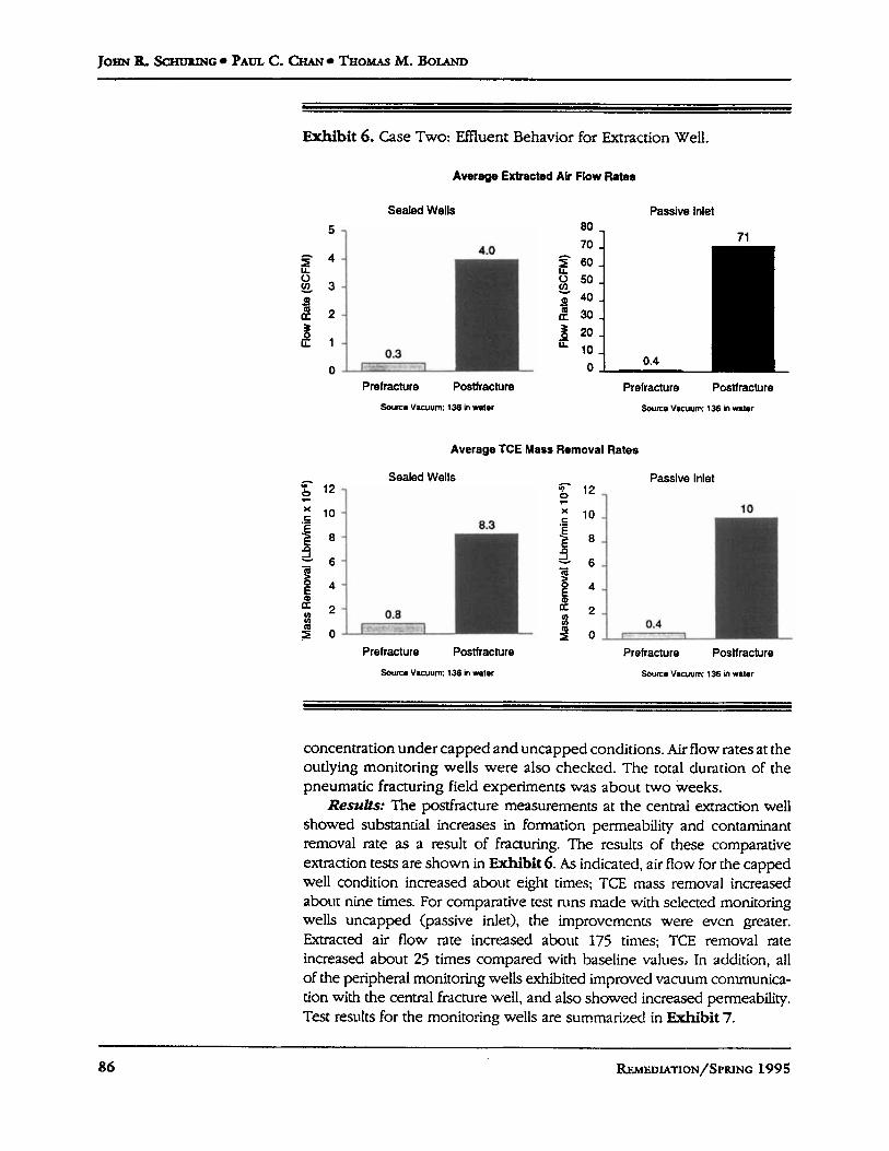
Exhibit 6. Case T w o Effluent Behavior for Extraction Well.
10
0.4 r- 1
Average Extracted Air Flow Rate.
Sealed Wells Passive Inlet
Prefracture Postfracture Prefracture Postfracture Source Vocuum: 138 in water Source Vacuum 136 in water
Average TCE Mass Removal Rates
Prefracture Postfracture Prefracture Postfracture
Sowe Vacuum: 136 in water Source Vacuum: 136 in water
concentration under capped and uncapped conditions. Airflow rates at the outlying monitoring wells were also checked. The total duration of the pneumatic fracturing field experiments was about two weeks.
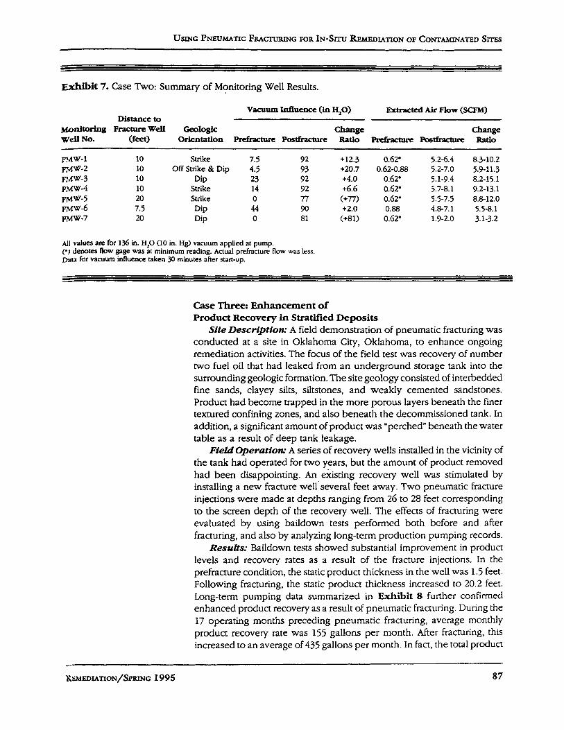
Results: The postfracture measurements at the central extraction well showed substantial increases in formation permeability and contaminant removal rate as a result of fracturing. The rcsults of these comparative extraction tests are shown in Exhibit 6. As indicated, air flow for the capped well condition increased about eight times; TCE mass removal increased about nine times. For comparative test nins made with selected monitoring wells uncapped (passive inlet), the improvcmcnts were even greater. Extracted air flow rate increased about 175 times; TCE removal rate increased about 25 times compared with baseline values.. In addition, all of the peripheral monitoring wells exhibited improved vacuum conmunica- tion with the central fracture well, and also showed increased permeability. Test results for the monitoring wells are summarized in Exhibit 7.
86 REMEDIATION/SPRINC 1995
USING PNEUMATIC FRACTURING FOR IN-SITU REMEDIATION OF CONTAMINATED SITES
a b i t 7. Case Two: Summary of Monitoring Well Results.
vacuum lnfluencc (in 40) Extracted Air Flow (SCFM) Distance to
Monitoring FractureWell Ceologic Change Change Well NO. (feet) orlentation P&kwAwe P~~tffacture Ratio &&actwe Posthmm Ratio
RAW-1 10 Strike 7.5 92 +12.3 0.62’ 5.2-6.4 8.3-10.2 m w - 2 10 Off Strike & Dip 4.5 93 +20.7 0.62-0.88 5.2-7.0 5.9-11.3 PMW-3 10 Dip 23 92 +4.0 0.62’ 5.1-9.4 8.2-15.1 WW-4 10 Strike 14 92 +6.6 0.62’ 5.7-8.1 9.2-13.1 PMW-5 20 Strike 0 n (+n> 0.62’ 5.5-7.5 8.8-12.0 FM “-6 7.5 Dip 44 90 +2.0 0.88 4.8-7.1 5.5-8.1 m w - 7 20 Dip 0 81 (+81) 0.62’ 1.9-2.0 3.1-3.2
AII values are for 136 in. H,O (10 in. H@ vacuum applied at pump. (*) denotes flow gage was at minimum reading. Actual prefrdcture flow was less. D A I ~ for vacuum influence raken 30 minutes after start-up.
Case Three: Enhancement of Product Recovery in StraWied Deposits
Site Descriptfotx A field demonstration of pneumatic fracturing was conducted at a site in Oklahoma City, Oklahoma, to enhance ongoing remediation activities. The focus of the field test was recovery of number two fuel oil that had leaked from an underground storage tank into the surrounding geologic formation. The site geology consisted of interbedded fine sands, clayey silts, siltstones, and weakly cemented sandstones. Product had become trapped in the more porous layers beneath the finer textured confining zones, and also beneath the decommissioned tank. In addition, a significant amount of product wils “perched” beneath the water table as a result of deep tank leakage.
FieU Operuttow A series of recovery wells installed in the vicinity of the tank had operated for two years, but the amount of product removed had been disappointing. An existing recovery well was stimulated by installing a new fracture well several feet away. Two pneumatic fracture injections were made at depths ranging from 26 to 28 feet corresponding to the screen depth of the recovery well. The effects of fracturing were evaluated by using baildown tests performcd both before and after fracturing, and also by analyzing long-term production pumping records.
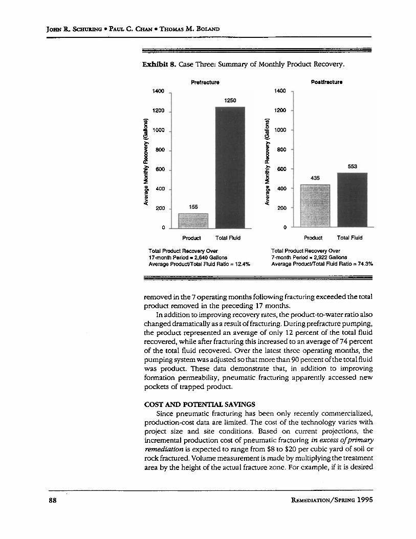
ResuZts: Baildown tests showed Substantial improvement in product levels and recovery rates as a result of the fracture injections. In the prefracture condition, the static product thickness in the well was 1.5 feet. Following fracturing, the static product thickness increased to 20.2 feet. Long-term pumping data summarized in Exhibit 8 further confirmed enhanced product recovery as a result of pneumatic fracturing. During the 17 operating months preceding pneumatic fracturing, average monthly product recovery rate was 155 gallons per month. After fracturing, this increased to an average of 435 gallons per month. In fact, the total product
- KWF.DIATION/SPRING 1995 87
JOHN fL SCHU~NG PAUL C. CHAN THOMAS M. BOLAND
Exhibit 8. Case Three: Summary of Monthly Product Recovery.
Pretracture
1400 1 1250
1200
g 1000
t 800
c2
a f 600 5
f 3
5 400
200
0
155
Product Total fluid
Total Product Recovery Over 17-month Period = 2,640 Gallons Average Product/Total Fluid Ratio = 12.4%
Poetfracture
1200 1400 1
Product Total Fluid
Total Product Recovery Over 7-mOnth Period = 2,922 Gallons Average ProductlTotal Fluid Ratio = 74.3%
removed in the 7 operating months following fracturing exceeded the total product removed in the preceding 17 months.
In addition to improving recovery rates, the product-to-water ratio also changed dramatically as a result of fracturing. During prefracture pumping, the product represented an average of only 12 percent of the total fluid recovered, while after fracturing this increased to an average of 74 percent of the total fluid recovered. Over the latest three operating months, the pumping system was adjusted so that more than 90 percent of the total fluid was product. These data demonstrate that, in addition to improving formation permeability, pneumatic fracturing apparently accessed new pockets of trapped product.
COST AND POTENTIAL SAVINGS Since pneumatic fracturing has been only recently commercialized,
production-cost data are limited. The cost of the technology varies with project size and site conditions. Based on current projections, the incremental production cost of pneumatic fracturing in excess ofprimary remediation is expected to range from $8 to $20 per cubic yard of soil or rock fractured. Volume measurement is made by multiplying the treatment area by the height of the actual fracture zone. For example, if it is desired
88 &,MEDIATION/sPRING 1995
USING PNEUMATIC FBACTURING FOR IN-SITU REMEDIATION OF CONTAMINATED S m
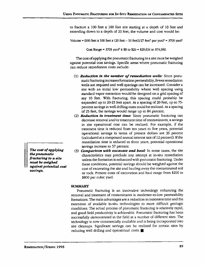
to fracture a 100 feet x 100 feet site starting at a depth of 10 feet and extending down to a depth of 20 feet, the volume and cost would be:
Volume = [lo0 feet x 100 feet x (20 feet - 10 feeOY27 f ed per yard3 - 3703 yard3
Cost Range = 3703 yard3 x $8 to $20 = $29,624 to $74,060.
The cost of applying the pneumatic fracturing to a site must be weighed against potential cost savings. Specific areas where pneumatic fracturing can reduce remediation costs include:
(1) Reduction in tbe number of remediation we&: Since pneu- matic fracturing increases formation permeability, fewer remediation wells are required and well spacings can be increased. Consider a site with an initial low permeability where well spacing using standard vapor extraction would be designed on a grid spacing of say 10 feet. With fracturing, this spacing could probably be expanded up to 20-25 feet apart. At a spacing of 20 feet, up to 75- percent savings in well drilling costs could be realized. At a spacing of 25 feet, the savings would range up to 84 percent.
(2) Reduction in treatment time: Since pneumatic fracturing can decrease removal and/or treatment time of contaminants, a savings in site operational cost can be realized. For example, if the treatment time is reduced From ten years to five years, potential operational savings in terms of present dollars are 36 percent (calcukated at a compound annual interest rate of 12 percent). If the remediation time is reduced to three years, potential operational savings increase to 57 percent.
(3) Comparison witb excavate and bauk In some cases, the site characteristics may,. preclude any attempt at in-situ remediation unless the formation is enhanced with pneumatic fracturing. Under these conditions, potential savings should be weighed against the cost of excavating the site and hauling away the contaminated soil or rock. Prescnt costs of excavation and haul range from $200 to $800 per cubic yard.
The cost of applying the pneumatic fracturing to a site must be weighed against potential cost savings.
SUMMARY Pneumatic fracturing is an innovative technology enhancing the
removal and treatment of contaminants in moderate-to-low permeability formations. The main advantages are a reduction in treatment time and the extension OF available in-situ technologies to more difficult geologic conditions. The actual process of pneumatic fracturing is relatively rapid, and good field productivity is achievable. Pneumatic fracturing has been successfully demonstrated in the field at a number of different sites. The technology is now commercially available and is being incorporated into site cleanups. Significant savings can bc realized For certain sites by reducing well drilling and Operational costs.
REMEDIATION/SPRING 1995 89
JOHN R ScwvaPJG PAUL C. CHAN THOMAS M. BOLAND
NOTES
1. Gidley, J.L., Holditch, S.A., Nierode, D.E. and Veatch, R.W., 1989. Recent Advunces fn Hydrauftc Frachrrtng, SPE, Richardson, Texas.
2. Schuring, J. and Chan, C. "Removal of Contaminants from the Vadose Zone by Pneumatic Fracturing," U.S. Geological Survey, Dept. of Interior, U.S.G.S. Award 14-08 0001-Gl739, January 1992.
3. Schuring, J., Valds, J. and Chan, P. "Pneumatic Fracturing of a Clay Formation to Enhance Removal of VOCs," Proceedings from the Fourteenth Annual Madison Waste Conference, Univ. of Wisconsin-Madison, Wisconsin, Sept. 1-31.
4. U.S. EPA Risk Reduction Engineering Laboratory, SITE Demonstration Project, "Accutech Pneumatic Fracturing Extraction and Hot Gas Injection, Phase 1," Applications Analysis Report, EPA/540/AR-93/509, July 1993. 5. Ziegler, T. W., 1976. "Determination ofRock Mass Permeability." Tech. Rept. S-76-2, U.S. Army Engineer WES, Vicksburg. Mississippi.
ACKNOWLEDGMENTS
This research was supported in part as a project o f the Hazardous Substance Management Research Center at New Jersey Institute of Technology; a National Science Foundation Industry/University Cooperative Research Center and an Advanced Technol- ogy Center of the New Jersey Commission on Science and Technology.
The authors wish to acknowledge the following companies and agencies for their support of this research and development effort: Accutech Remedial Sysrem, AT&T, Battelle Memorial Institute, BP America, McLaren Hart Environmental Engineering Corpo- ration, Malcolm-l'irnie, Inc., Science Applications International CoprJtion, U S . Air Force, U.S. Depaflment of Enerby, and U.S. Environmental Protection Agency.
In the cotirse of a project of this size and duration, inany individuals have contributed a great deal. The authors wish to acknowledge the past and present student research assistants on the pneumatic fracturing project: Firoz Ahmcd, Cmiy Uruening, Rocio Cadilb Durand, James Chang, Brian Corb, Yuan Ding, Conan Fitzgerald, k t t y Gonzalez, Frank Gnczyk, Heather Hall, Trevor King, Sean McGonigJl, DeepJk Nautiyal, Norman Ng, Atiqur Rahman, Osvaldo Rodriguez, Panayiotis Papanicolaou, Surcsh Puppala, Pramnni Ratnaween, Nikesh Shah, Ellen Sheridan, Brian Sielski, Madcep Talwar, and Anthony Vandeven.
90 REMEDIATION/SPRING 1995