using enterprise architect (ea) -...
TRANSCRIPT
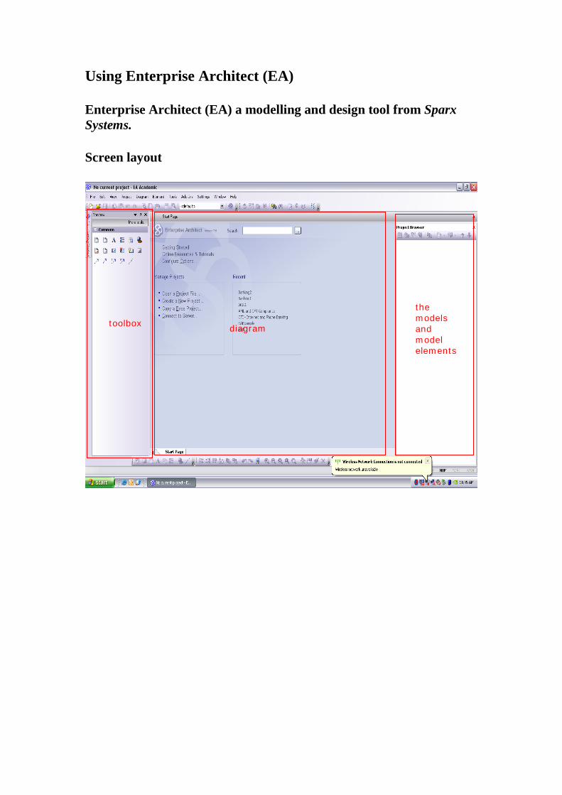
Using Enterprise Architect (EA) Enterprise Architect (EA) a modelling and design tool from Sparx Systems. Screen layout
toolbox diagram
the models and model elements
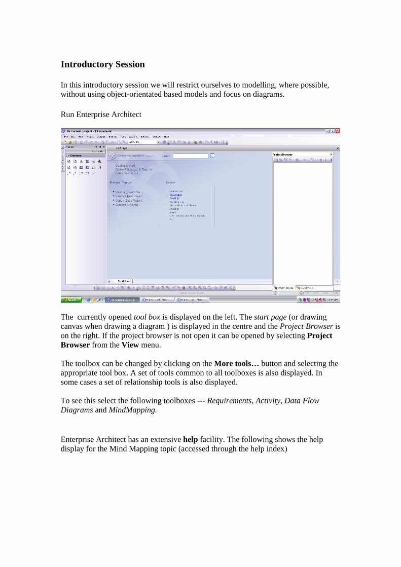
Introductory Session In this introductory session we will restrict ourselves to modelling, where possible, without using object-orientated based models and focus on diagrams. Run Enterprise Architect
The currently opened tool box is displayed on the left. The start page (or drawing canvas when drawing a diagram ) is displayed in the centre and the Project Browser is on the right. If the project browser is not open it can be opened by selecting Project Browser from the View menu. The toolbox can be changed by clicking on the More tools… button and selecting the appropriate tool box. A set of tools common to all toolboxes is also displayed. In some cases a set of relationship tools is also displayed. To see this select the following toolboxes --- Requirements, Activity, Data Flow Diagrams and MindMapping. Enterprise Architect has an extensive help facility. The following shows the help display for the Mind Mapping topic (accessed through the help index)
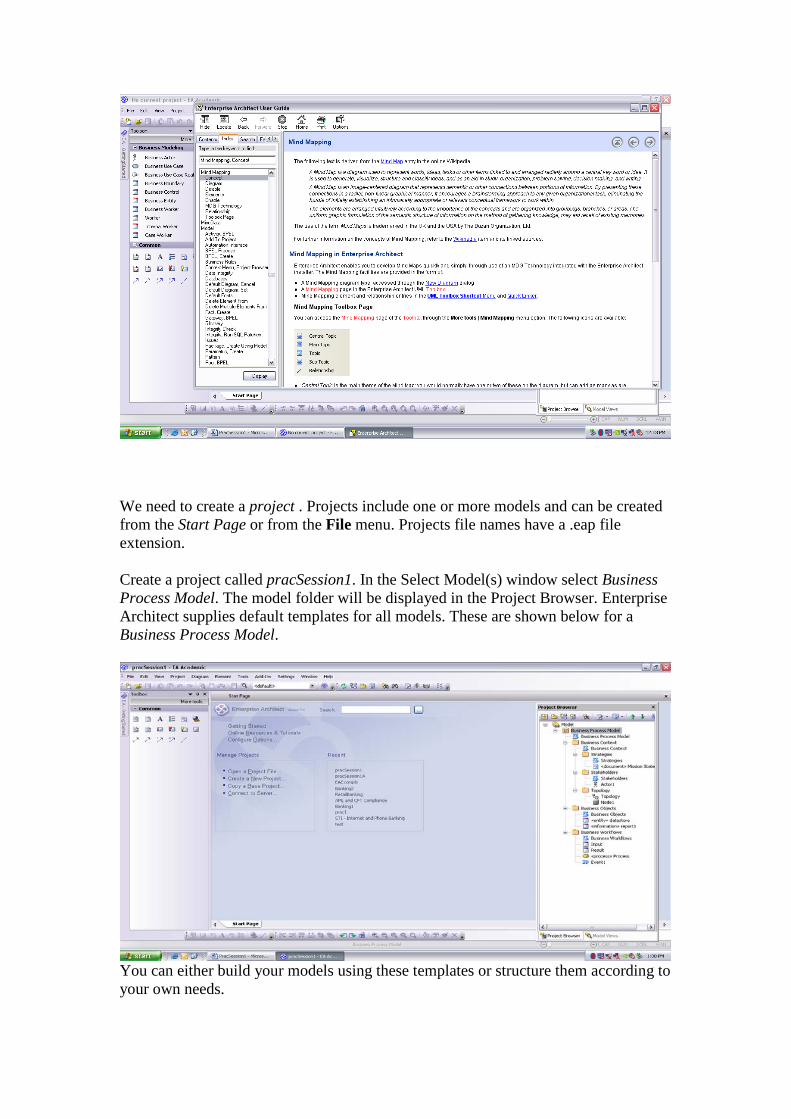
We need to create a project . Projects include one or more models and can be created from the Start Page or from the File menu. Projects file names have a .eap file extension. Create a project called pracSession1. In the Select Model(s) window select Business Process Model. The model folder will be displayed in the Project Browser. Enterprise Architect supplies default templates for all models. These are shown below for a Business Process Model.
You can either build your models using these templates or structure them according to your own needs.
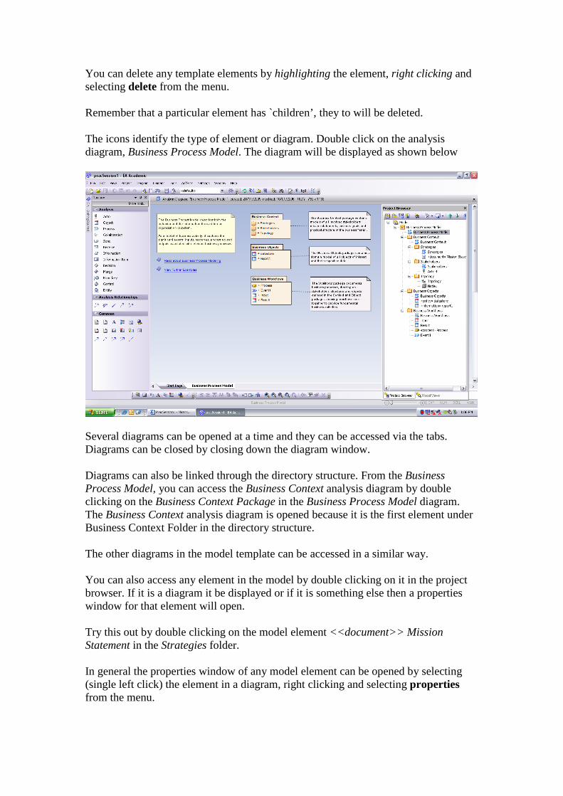
You can delete any template elements by highlighting the element, right clicking and selecting delete from the menu. Remember that a particular element has `children’, they to will be deleted. The icons identify the type of element or diagram. Double click on the analysis diagram, Business Process Model. The diagram will be displayed as shown below
Several diagrams can be opened at a time and they can be accessed via the tabs. Diagrams can be closed by closing down the diagram window. Diagrams can also be linked through the directory structure. From the Business Process Model, you can access the Business Context analysis diagram by double clicking on the Business Context Package in the Business Process Model diagram. The Business Context analysis diagram is opened because it is the first element under Business Context Folder in the directory structure. The other diagrams in the model template can be accessed in a similar way. You can also access any element in the model by double clicking on it in the project browser. If it is a diagram it be displayed or if it is something else then a properties window for that element will open. Try this out by double clicking on the model element <<document>> Mission Statement in the Strategies folder. In general the properties window of any model element can be opened by selecting (single left click) the element in a diagram, right clicking and selecting properties from the menu.
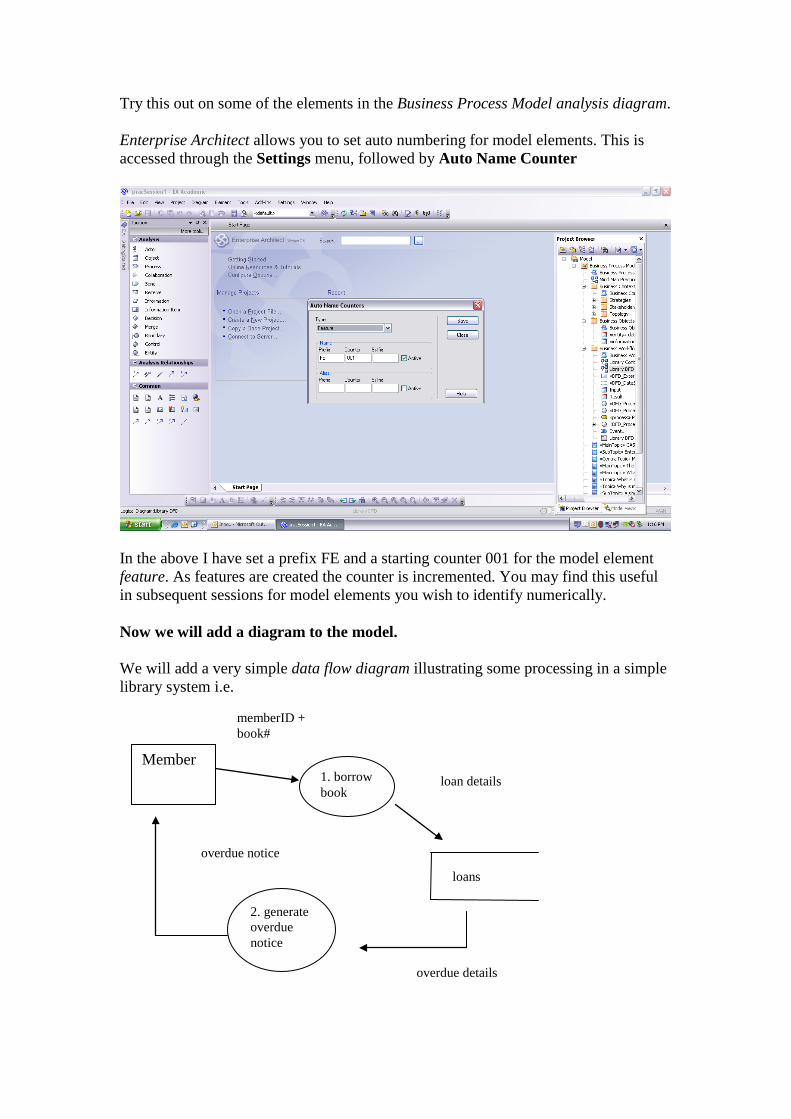
Try this out on some of the elements in the Business Process Model analysis diagram. Enterprise Architect allows you to set auto numbering for model elements. This is accessed through the Settings menu, followed by Auto Name Counter
In the above I have set a prefix FE and a starting counter 001 for the model element feature. As features are created the counter is incremented. You may find this useful in subsequent sessions for model elements you wish to identify numerically. Now we will add a diagram to the model. We will add a very simple data flow diagram illustrating some processing in a simple library system i.e.
Member 1. borrow book
2. generate overdue notice
loans
loan details
overdue details
overdue notice
memberID + book#
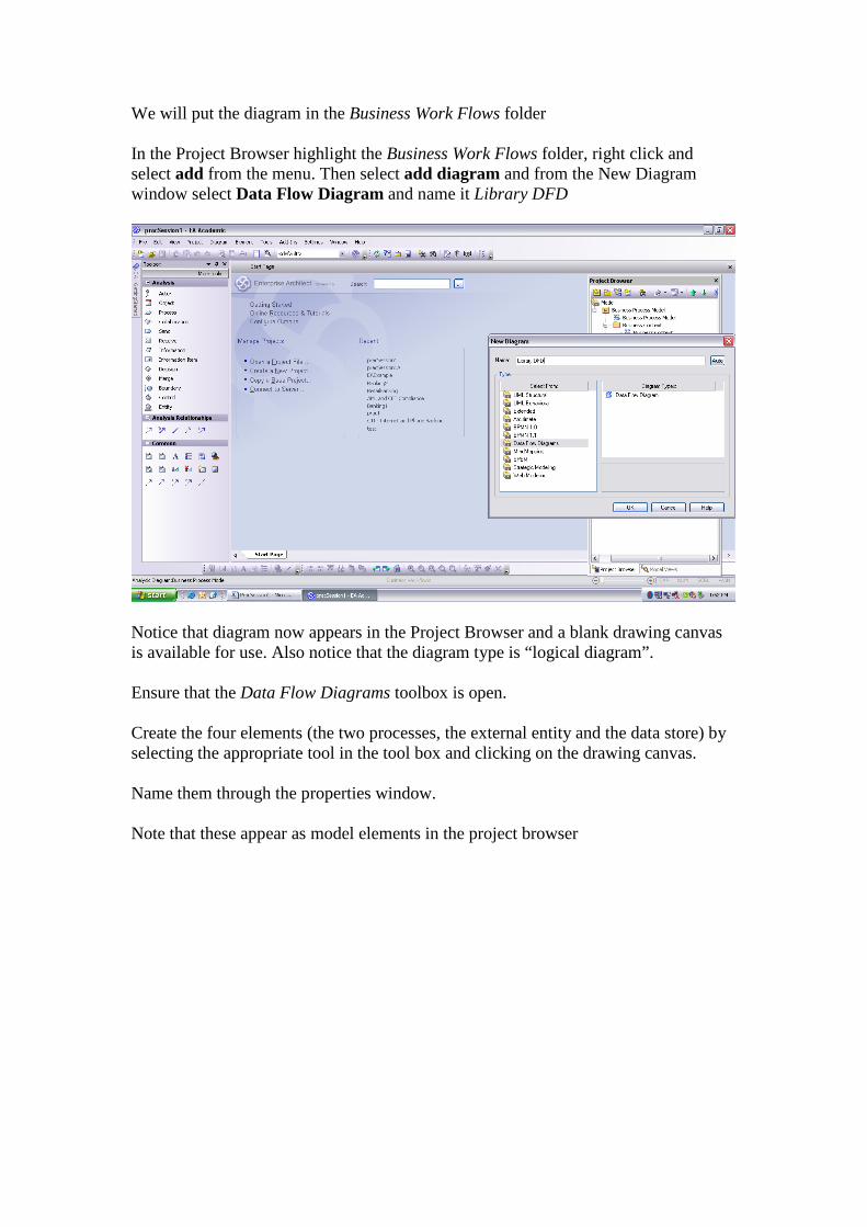
We will put the diagram in the Business Work Flows folder In the Project Browser highlight the Business Work Flows folder, right click and select add from the menu. Then select add diagram and from the New Diagram window select Data Flow Diagram and name it Library DFD
Notice that diagram now appears in the Project Browser and a blank drawing canvas is available for use. Also notice that the diagram type is “logical diagram”. Ensure that the Data Flow Diagrams toolbox is open. Create the four elements (the two processes, the external entity and the data store) by selecting the appropriate tool in the tool box and clicking on the drawing canvas. Name them through the properties window. Note that these appear as model elements in the project browser

Now create the data flows in the same way. Select the data flow tool in the toolbox, then select the appropriate element as the source and drag the mouse to the target element They are labelled through the dependencies properties window. To access this select the data flow, right click and select dependencies properties. Also notice that you select an appropriate line style for the data flow from the dependencies properties window or by selecting the data flow, right clicking and selecting line styles from the menu Also note that subtle changes can made to the connectors (in this case data flows) by accessing the Tidy Line Angles menu selection. Now add a note to the diagram, explaining what it is. A note is one of the common tools available with all toolkits
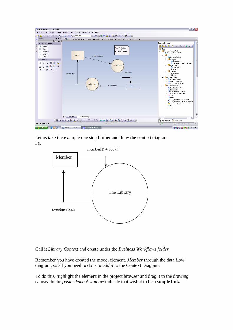
Let us take the example one step further and draw the context diagram i.e.
Call it Library Context and create under the Business Workflows folder Remember you have created the model element, Member through the data flow diagram, so all you need to do is to add it to the Context Diagram. To do this, highlight the element in the project browser and drag it to the drawing canvas. In the paste element window indicate that wish it to be a simple link.
The Library
Member
memberID + book#
overdue notice
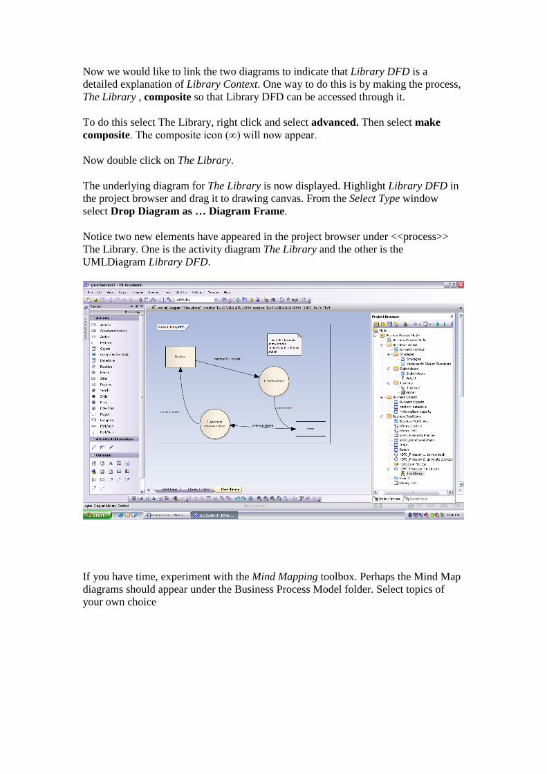
Now we would like to link the two diagrams to indicate that Library DFD is a detailed explanation of Library Context. One way to do this is by making the process, The Library , composite so that Library DFD can be accessed through it. To do this select The Library, right click and select advanced. Then select make composite. The composite icon (∞) will now appear. Now double click on The Library. The underlying diagram for The Library is now displayed. Highlight Library DFD in the project browser and drag it to drawing canvas. From the Select Type window select Drop Diagram as … Diagram Frame. Notice two new elements have appeared in the project browser under <<process>> The Library. One is the activity diagram The Library and the other is the UMLDiagram Library DFD.
If you have time, experiment with the Mind Mapping toolbox. Perhaps the Mind Map diagrams should appear under the Business Process Model folder. Select topics of your own choice