using curve tracing to detect counterfeit …...curve tracing equipment manual curve tracers limited...
TRANSCRIPT
Copyright © 2010 Robson Technologies, Inc.
Using Curve Tracing to Detect Counterfeit Components
Chris O’Connor
Robson Technologies Inc.
Morgan Hill, CA
SMTA Expo and Tech Forum
November 20, 2013
Contact RTI for a longer
more in depth version of
this presentation
All contents of this presentation copyright Robson Technologies Inc. 2013
Copyright © 2010 Robson Technologies, Inc.
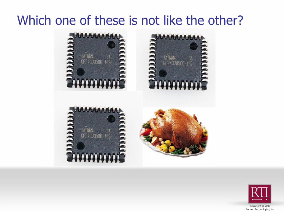
Which one of these is not like the other?
Copyright © 2010 Robson Technologies, Inc.
When to suspect devices
Red Flags for High Risk Parts
Untraceable old stock
Old date codes
Hard to find devices
High Value devices
Not Purchased from the OEM or an authorized
distributor
Speed Graded devices
High Reliability devices
Copyright © 2010 Robson Technologies, Inc.
Types of Counterfeits What types of counterfeit devices are there?
Complete fakes Random function remarked devices, only the package
resembles what was ordered
Rebranded, Imitation or Copy Components Similar function but from an unknown source
Rejected Components Real but otherwise previously failed devices
Recycled Components Real but otherwise previously used devices
80 to 90 % of all counterfeits*
Remarked Components Same function but inferior specs
Source: SMT Corp. as reported by IEEE Spectrum October 2013 issue
“ The Hidden Dangers of Chop-Shop Electronics”
Copyright © 2010 Robson Technologies, Inc.
Question: How can this be done; Verify that an IC you bought is genuine and quality, that it is not remarked, repackaged, reused or fake?
Answer: Test it and compare it to known good devices. There are many tests available. Some analyze the Physical aspects of the device, some analyze the electrical aspects
Detection Methods
Copyright © 2010 Robson Technologies, Inc.
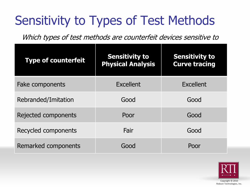
Sensitivity to Types of Test Methods Which types of test methods are counterfeit devices sensitive to
Type of counterfeit Sensitivity to
Physical Analysis Sensitivity to Curve tracing
Fake components Excellent Excellent
Rebranded/Imitation Good Good
Rejected components Poor Good
Recycled components Fair Good
Remarked components Good Poor
Copyright © 2010 Robson Technologies, Inc.
What is Curve Tracing? Curve Tracing was originally developed to
characterize electron tubes and later transistors and other power semiconductors.
Used to measure DC Electrical Parameters of discrete semiconductors
Can be used as a tool for screening devices Workhorse tool of the Failure Analysis lab Universal Non-Destructive Electrical Test Tool Characterizes damage to IC structures Measures damage to electronic structures Stimulate electrical damage for fault
localization methods
Copyright © 2010 Robson Technologies, Inc.
Where Curve Tracing is used?
In what way should I be using a curve tracer?
Incoming Receiving and Inspection
High Reliability Manufacturing
Part Recovery Operations
Failure Analysis
Copyright © 2010 Robson Technologies, Inc.
Who uses Curve Tracing
Who is using curve tracing for counterfeit interdiction?
High Reliability manufacturers
Distributors
Part Recovery providers
Law Enforcement
Laboratory and Analysis Service Providers
Copyright © 2010 Robson Technologies, Inc.
Curve Traces are made up of measurements of voltage and current In Ohms Law; V=I*Z where Z is the impedance of the device or pin In semiconductor devices, Z is usually nonlinear Z changes as the voltage across the load changes
A Curve Tracer’s task is to trace out that relationship and convert it into a graph of I vs. V
Each type of pin has a “characteristic” curve trace shape particular to that pin’s structure
Collectively the Characteristics of all the pins of a given device provide a sufficient signature or fingerprint for checking device authenticity.
I-V Curve Tracing
Copyright © 2010 Robson Technologies, Inc.
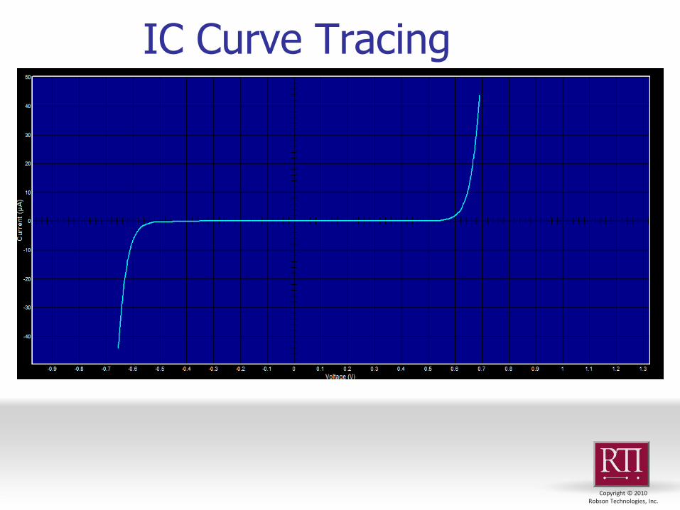
IC Curve Tracing

Copyright © 2010 Robson Technologies, Inc.
Copywrite © 2009 Robson Technologies, Inc.
Curve Tracing Methods
Hypothetical Model of a CMOS IC circuit

Copyright © 2010 Robson Technologies, Inc.
IC Curve Tracing The most basic Curve Tracing tasks is to acquire a
set of signatures for each device and save that information so that it can be compared to other devices
This comparison task is the central method for finding bad devices
If the curve trace results of a suspect device do not match those of a known good and genuine part, then that device is either degraded or different from the known device.
Copyright © 2010 Robson Technologies, Inc.
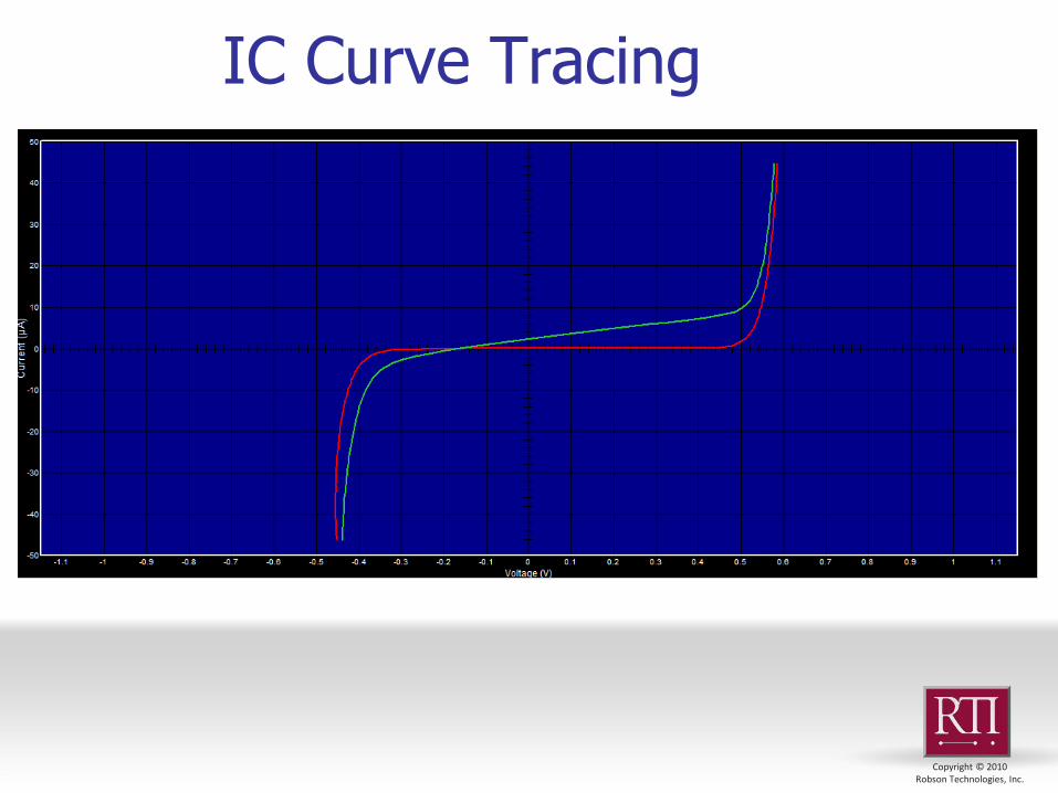
IC Curve Tracing
Copyright © 2010 Robson Technologies, Inc.
Collectively the Characteristics of all the pins of a given device provide a sufficient signature or fingerprint for checking device authenticity
If the curve trace results of a suspect device do not match those of a known good and genuine part, then that device is either degraded or different from the known device
IC Curve Tracing
Copyright © 2010 Robson Technologies, Inc.
Each set of test conditions produces a unique set of curve trace results. Using multiple test conditions is like getting finger prints from the whole hand. Matching that to a suspect device becomes much more reliable.
Test Conditions

Copyright © 2010 Robson Technologies, Inc.
IC Curve Tracing
Copyright © 2010 Robson Technologies, Inc.
Curve Tracing Equipment Manual Curve tracers
Limited test conditions, primarily “hand test” Low entry cost
Automated Curve Tracers Very flexible for IC characterization Designed specifically for characterizing IC devices Offers a balance between Precision and Flexibility Allows for screening devices to a tight tolerance,
accuracy and repeatability Flexibility for a wider range of devices Wide variety of test conditions

Copyright © 2010 Robson Technologies, Inc.
Curve Tracing Equipment Automated Curve Tracers
Configurable multi channel switch matrixes Multiple SMU (Source Measure Units) available Obtain I-V Signature and IDD Provide multiple bias voltage or current to devices Allows for testing in the powered up state Measurements are generally high precision Software is optimized for configuring various test
conditions and analyzing the piles of data that can be produced
Copyright © 2010 Robson Technologies, Inc.
Curve Trace Methods
Three generic test methods sufficiently characterize any device of any technology
Unpowered Curve Tracing
Powered Curve tracing
Supply Current Characterization
Copyright © 2010 Robson Technologies, Inc.
Unpowered Curve Tracing The Unpowered Curve Trace method
First line of defense
Simplest test method
Lowest cost hardware
Compare known good devices to all or selected samples from a batch of parts to screen out the worst of the bunch
Copyright © 2010 Robson Technologies, Inc.
Copywrite © 2009 Robson Technologies, Inc.
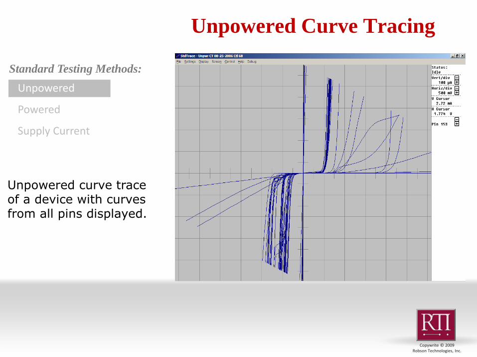
Unpowered Curve Tracing
Unpowered
Powered
Supply Current
Standard Testing Methods:
Unpowered curve trace of a device with curves from all pins displayed.
Copyright © 2010 Robson Technologies, Inc.
Unpowered Curve Tracing What to look for in an unpowered curve trace result
Non matching characteristics: Certainly with any test condition, if the curves from a suspect device don’t match the golden device you have a problem
If it’s a complete mismatch, it’s safe to say that either the device is severely damaged or it is not the same device entirely
Smaller variations can be clues to ESD damage, silicon differences or other quality issues.
Copyright © 2010 Robson Technologies, Inc.
Unpowered Curve Tracing
Things Unpowered curve tracing will find Failures: Devices with gross damage characterized by Open pins,
shorted pins or high leakage Incorrectly bonded devices Fake or wrong die inside Different rev die inside Device matches datasheet pin out
Things Unpowered Curve tracing will not find Remarked devices Reused devices that are good electrically Most forms of damaged package devices with no electrical damage Some Functional Failures; Analog or Digital
Copyright © 2010 Robson Technologies, Inc.
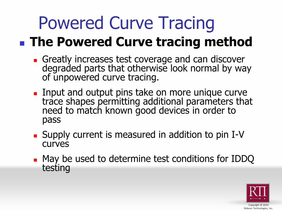
Powered Curve Tracing The Powered Curve tracing method
Greatly increases test coverage and can discover degraded parts that otherwise look normal by way of unpowered curve tracing.
Input and output pins take on more unique curve trace shapes permitting additional parameters that need to match known good devices in order to pass
Supply current is measured in addition to pin I-V curves
May be used to determine test conditions for IDDQ testing
Copyright © 2010 Robson Technologies, Inc.
Copywrite © 2009 Robson Technologies, Inc.
Powered Curve Tracing
Unpowered
Powered
Supply Current
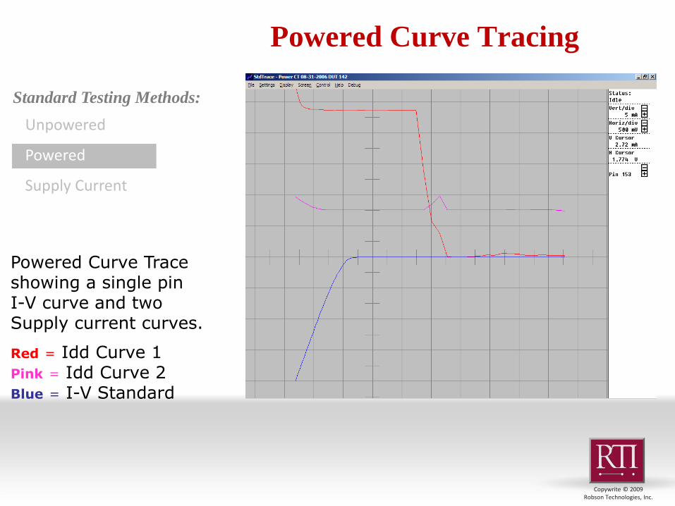
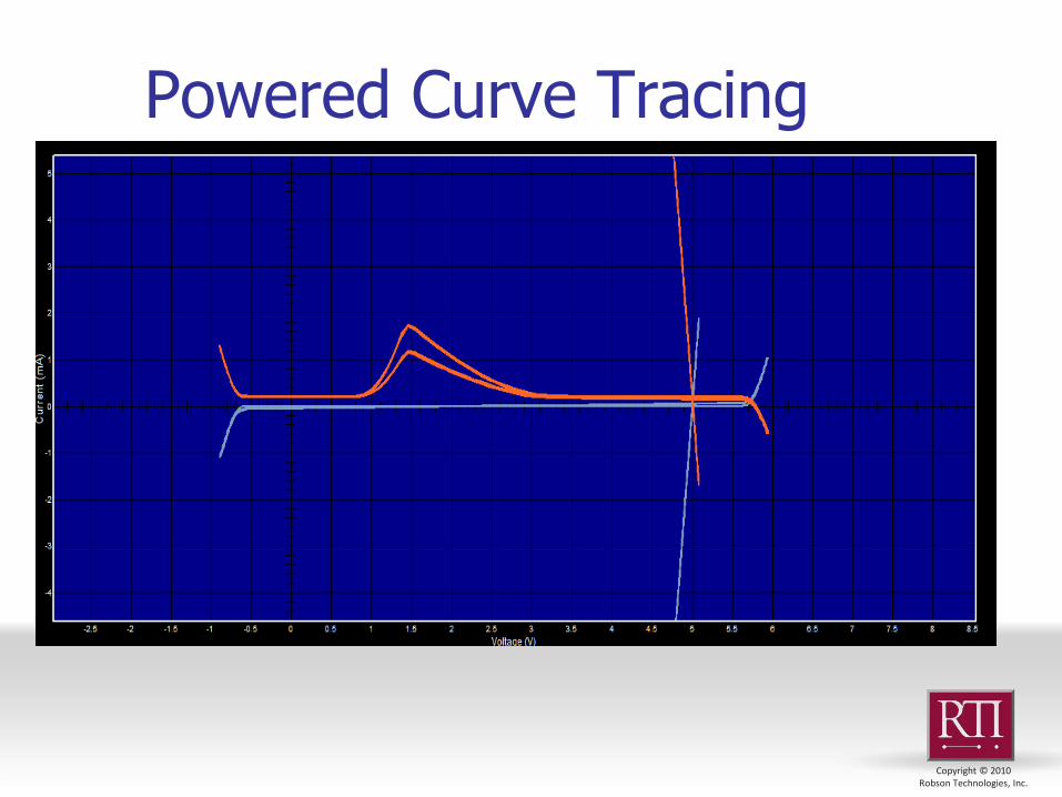
Powered Curve Trace showing a single pin I-V curve and two Supply current curves.
Red = Idd Curve 1 Pink = Idd Curve 2 Blue = I-V Standard
Standard Testing Methods:
Copyright © 2010 Robson Technologies, Inc.
Powered Curve Tracing

Copyright © 2010 Robson Technologies, Inc.
Powered Curve Tracing
Things Powered curve tracing will find Same failures as Unpowered curve tracing Degraded inputs or outputs High Supply Current Other supply current switching anomalies
Things Powered Curve tracing will not find Remarked devices Reused devices that are good electrically Functional only Failures; Analog or Digital
Copyright © 2010 Robson Technologies, Inc.
Supply Current Characterization
Broadest test coverage
Many problems show up in the supply current
Simplest Results
Just a few simple numbers to collect
IDDQ can be measured in any state of the device which you can configure repeatably
A testable state does not necessarily need to be to an actual functionally valid state.
Measure IDD from different power domains for greater test coverage
Copyright © 2010 Robson Technologies, Inc.
Supply Current Characterization
Supply current can be measured using other methods like bench supplies and a breadboard
Current limits should be set to protect test hardware from burning due to over current short circuit
Use the Powered Curve trace to get a broader view of the supply current range and which pins influence it most.
Choose test conditions based on powered curve trace analysis but screen devices quickly using IDDQ checks
Copyright © 2010 Robson Technologies, Inc.
Supply Current Characterization
Things IDD testing will find Very High IDD indicates a shorted device
High IDD in any state indicates damage to the core or pins
High IDD may accompany other forms of electrical damage
High IDD only in certain states indicates damaged subcircuits
Marginally High or low IDD may indicate a degraded device
Low IDD indicates a circuit that will not activate
Low IDD may indicate missing or fused open bond wires
Zero IDD indicates fused open power traces or bond wires
Copyright © 2010 Robson Technologies, Inc.
Supply Current Characterization
Things IDD testing will not find
Damage to inputs, outputs and I/O pins that do not result in a short to a supply
Low level leakage caused by ESD
Functional only failures
Analog Non Compliance
Dynamic or speed related non compliance
Package quality problems
Copyright © 2010 Robson Technologies, Inc.
Evaluating Results Comparing to a known good device
Most reliable method when known good devices are available
Test more than 1 known good device to learn acceptable variability
Comparing to the average device
Collect curve trace data from a lot of devices and look at each pin as a group
Copyright © 2010 Robson Technologies, Inc.
Evaluating Results DataTrace post processing software has features
designed exclusively for evaluating counterfeit devices and evaluating lots of devices
Batch Comparison presents results in bar charts and tables
A group of devices that all match well and also match old lots you have previously saved will have high confidence
A group of devices with poor match or high failure rate especially as compared to the past lots will have poor confidence
Copyright © 2010 Robson Technologies, Inc.
Evaluating Results

Copyright © 2010 Robson Technologies, Inc.
Complete fakes These are devices with packaging and markings that may resemble the authentic device but
the die inside may be anything but what you thought.. In these the electrical continuity
does not come close to matching the genuine device.
Unpowered curve tracing has a high sensitivity to this kind of counterfeit. Mismatched curves, opens and shorts should be evident on most pins.
Curves can be evaluated against the datasheet when no known
good device is available
Powered curve tracing and supply current measurements are usually not necessary due to the clear indication from unpowered
Physical test methods also do very well at spotting these fakes These devices are generally easy to spot through marking analysis, decap or x-ray inspection
Evaluating Results
Copyright © 2010 Robson Technologies, Inc.
Rebranded, Imitation or Copy devices These are devices where the counterfeiter actually made an effort to supply a functional device.
Basic functional testing may pass and they might even work in your product.
Even minor changes in an IC design can change the fingerprint of the curve traces, Curve Tracing turns out to be quite sensitive to this type of fake. While a row of pins may have the same name, if the device inside does not match exactly, the curves will be different, sometimes very different.
Unpowered curve tracing has a moderate to high sensitivity because if the pin input structure is different like say from a different process, the curve will be somewhat different.
Since the device was intended to be functionally equivalent, the powered curve tracing, might even be more compliant. However clues in the supply current, IDD switching characteristics and clamp diode forward resistance can show up
Physical test methods have a good chance at finding these since the die or other construction details may be different. Since the package as well as the die inside may be fake, most of the methods should have some sensitivity
Evaluating Results
Copyright © 2010 Robson Technologies, Inc.
Rejected devices These are devices that have failed at the factory and were somehow reclaimed by
counterfeiters. As good as these devices appear physically, just about every one of them is an electrical failure
Curve tracing will find most of these failures. Any failure mode related to a pin is detectable, only deep core functional failures will be undetectable by curve tracing
Unpowered curve tracing will have good to very good sensitivity and
adding powered curve tracing with its supply current measurements will increase the detection rate to high sensitivity
Physical test methods will miss these failed but otherwise authentic devices. For these devices the die inside is real and so is the package and may be undetectable by Marking Analysis, X-Ray, or even internal visual inspection after decap. Tracing the date or lot codes may lead to evidence of scrapping by the OEM
Evaluating Results
Copyright © 2010 Robson Technologies, Inc.
Reclaimed devices These are or were authentic devices at one time but they are used now. They were once
soldered to a PC board assembly and may have even seen a service life. At some point the assembly was scrapped and some devices were recovered.
Unpowered curve tracing has fair sensitivity to these because many may not have electrical failures.
Powered curve tracing has the same limitation
If the device is failed; both curve tracing methods have a very good chance of detecting it
Physical test methods may detect that the leads are reconditioned or mechanical damage to the package but there may be no other package anomalies and the markings may be authentic.
Evaluating Results
Copyright © 2010 Robson Technologies, Inc.
Remarked devices These are otherwise genuine devices remarked in such a way as to make them more
valuable for resale. The device inside may or may not be identical to the actual device.
This type of counterfeit is the one type that curve tracing is not very good at finding. The devices inside are otherwise good devices matching the known good specimen with respect to its DC characteristics and pin types. The differences lie in the functional properties or maximum AC operation speed. These are areas of electrical test that curve tracing does not do.
Physical analysis methods have a very high sensitivity to this type of counterfeit. Marking analysis can confirm the validity of things like date codes for the particular part number or consistency of part number suffixes. Such analysis will often reveal discrepancies that will lead to detection of fake part codes or specifics.
Evaluating Results
Copyright © 2010 Robson Technologies, Inc.
Curve tracing can be used to detect a wide range of counterfeit or misrepresented IC devices.
Unpowered curve tracing is used to confirm the pinout and check
for gross defects Powered Curve tracing goes beyond a reasonable match to
confirm many of the DC specifications including supply current. This increases counterfeit detection greatly
Curve tracing is especially good at finding ESD damaged or high
Supply Current (IDDq) caused by mishandling that may degrade or reduce the lifetime in the application circuit
When used with device markings analysis and physical analysis
methods, curve tracing can close the net the rest of the way on nearly all misrepresented devices
Conclusion

Copyright © 2010 Robson Technologies, Inc.
Users can create libraries of known good devices (KGD) for comparison to suspect parts
Users can save results from each purchased lot and chart the
failures in production. This method helps pinpoint signatures of good and bad devices.
Old lots can be used as known good devices for future lot testing. Curve tracing requires minimal information about the function of
the device. A list of pin names and pin type is usually all one needs for a thorough analysis.
Curve tracing is universal to any semiconductor technology and
any device package.
Conclusion