using cppsim to generate neural network modules in...
TRANSCRIPT
Using CppSim to Generate Neural Network Modules in Simulink using the simulink_neural_net_gen command
Michael H. Perrott
http://www.cppsim.com
June 24, 2008
Copyright © 2008 by Michael H. Perrott All rights reserved.
Table of Contents Introduction ............................................................................................................................................. 1 Importing the Example............................................................................................................................ 1 Highlights of Example ............................................................................................................................ 4
A. Schematic of Neural Node ............................................................................................................. 4 B. Overall Network Topology............................................................................................................. 5 C. Specification of Network Interconnection...................................................................................... 6 D. Running the Example in Matlab/Simulink..................................................................................... 9
Specification of the Neural Net Interconnection................................................................................... 12 Introduction CppSim offers a convenient way of realizing neural networks by using a graphical environment to create the neural node and files to specify the connectivity between the nodes and the overall input and output of the network. CppSim creates all of the interface code that is needed to turn the resulting neural net into a Simulink S-Function block. Given that the user has access to a suitable C++ compiler (such as Microsoft Visual C++), the S-Function code is compiled by the user and the block can then be used within Simulink. Importing the Example To explain the basic operation of using the ‘simulink_neural_net_gen:’ command in CppSim, we will work through an example. It is assumed that the user has installed CppSim on their computer (downloaded from http://www.cppsim.com), downloaded the file neural_net_example.tar.gz from http://www.cppsim.com, and has also installed a suitable C++ compiler for Matlab mex and S-function compilation (such as Microsoft Visual C++). For issues related to installation and general use of CppSim, please refer to the CppSim Primer available at http://www.cppsim.com. Also, one should note that Microsoft provides a free “Express” version of their C++ compiler that can be used to compile mex files in Matlab. Please see the link http://www.mathworks.com/matlabcentral/fileexchange/22689 for details.
1
• Place the file neural_net_example.tar.gz in the directory c:/CppSim/Import_Export. Note that we have assumed that the root installation directory for CppSim is c:/CppSim in this case – please modify the above directory location if appropriate.
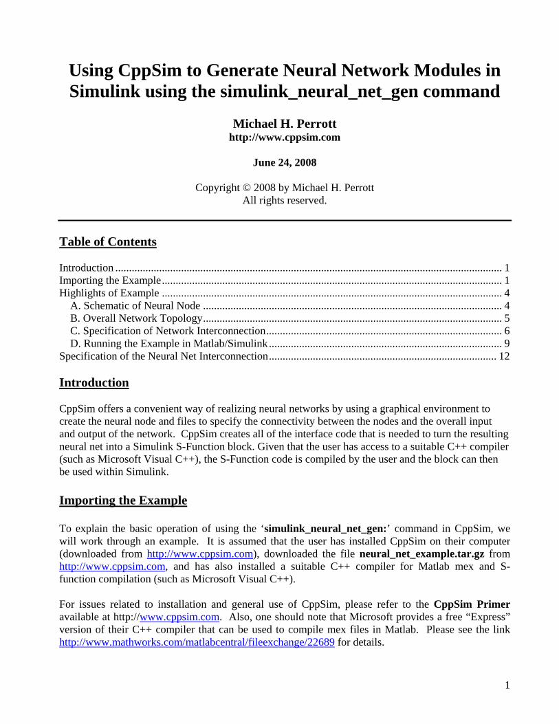
• Open up Sue2 by clicking on its icon on the Windows Desktop. • Within Sue2, select Library Manager under the Tools menu item as shown in the figure
below:
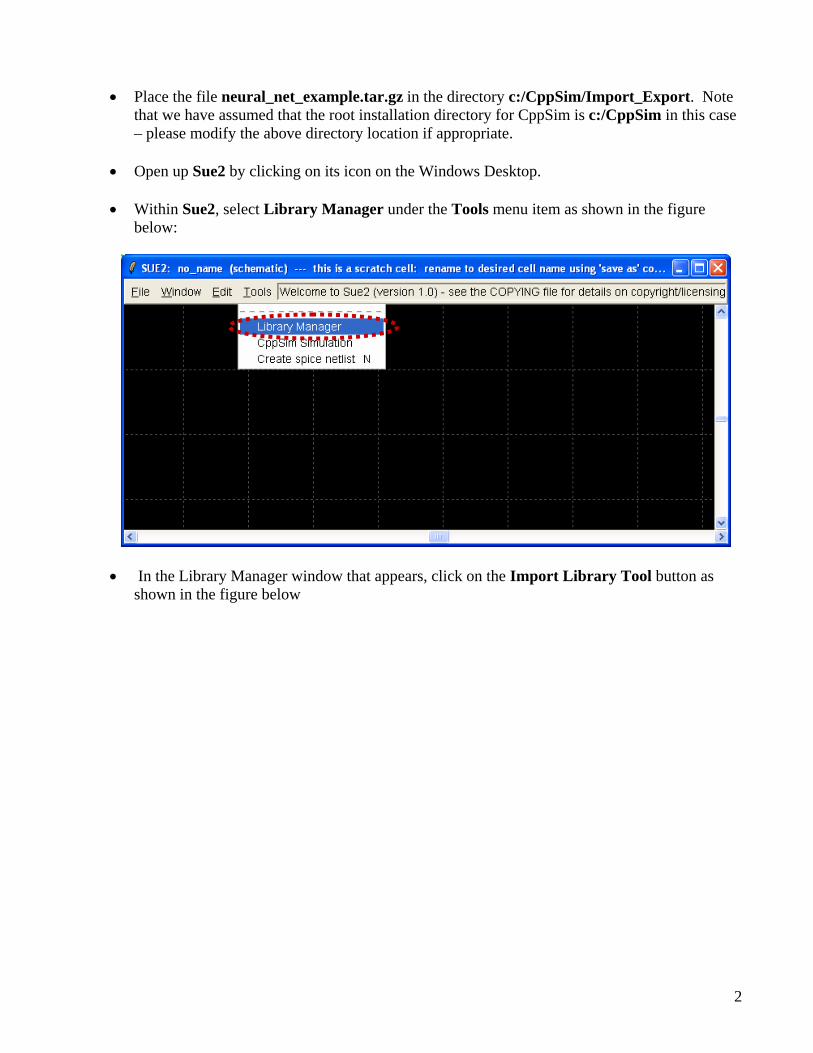
• In the Library Manager window that appears, click on the Import Library Tool button as shown in the figure below
2
• In the Import CppSim Library window that now appears, you should see neural_net_example.tar.gz appear as a Source File/Library as shown in the figure below. If you do not see this file, it means that you need to place it in the c:/CppSim/Import_Export directory.
3
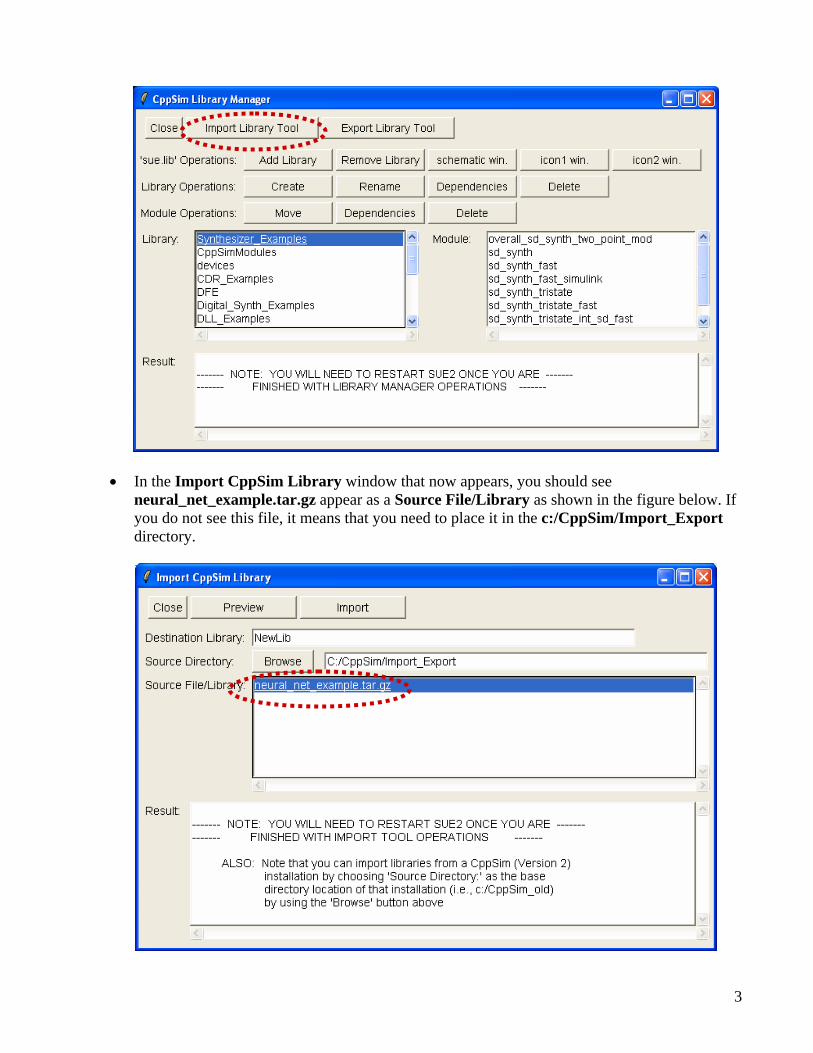
• Change the Destination Library to Neural_Net_Example as shown in the figure below. Once you have done so, you need to re-click on the neural_net_example.tar.gz file to select it, and then push the Import button. After the modules have been imported, exit from Sue2 and then restart it.
Highlights of Example We will now work through the example that was contained in the neural_net_example.tar.gz file. To complete this example, you will need to have access to Matlab, Simulink, and an appropriate C++ compiler for compiling Matlab mex files and S-functions (such as Microsoft Visual C++ Version 6 or later).
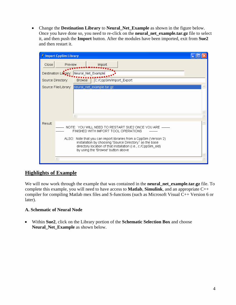
A. Schematic of Neural Node • Within Sue2, click on the Library portion of the Schematic Selection Box and choose
Neural_Net_Example as shown below.
4
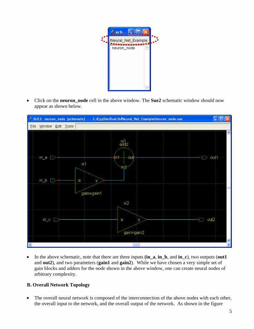
• Click on the neuron_node cell in the above window. The Sue2 schematic window should now appear as shown below.
• In the above schematic, note that there are three inputs (in_a, in_b, and in_c), two outputs (out1 and out2), and two parameters (gain1 and gain2). While we have chosen a very simple set of gain blocks and adders for the node shown in the above window, one can create neural nodes of arbitrary complexity.
B. Overall Network Topology • The overall neural network is composed of the interconnection of the above nodes with each other,
the overall input to the network, and the overall output of the network. As shown in the figure 5
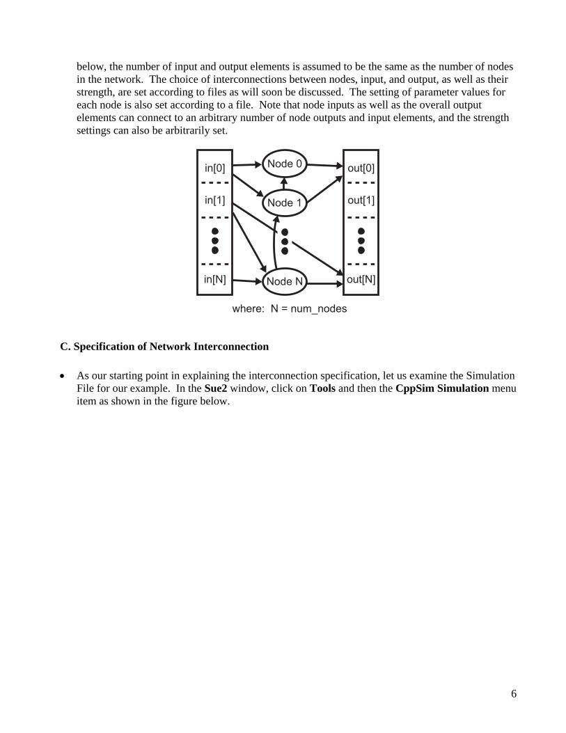
below, the number of input and output elements is assumed to be the same as the number of nodes in the network. The choice of interconnections between nodes, input, and output, as well as their strength, are set according to files as will soon be discussed. The setting of parameter values for each node is also set according to a file. Note that node inputs as well as the overall output elements can connect to an arbitrary number of node outputs and input elements, and the strength settings can also be arbitrarily set.
Node 0in[0]
in[1]
in[N]
out[0]
out[1]
out[N]Node N
Node 1
where: N = num_nodes
C. Specification of Network Interconnection • As our starting point in explaining the interconnection specification, let us examine the Simulation
File for our example. In the Sue2 window, click on Tools and then the CppSim Simulation menu item as shown in the figure below.
6
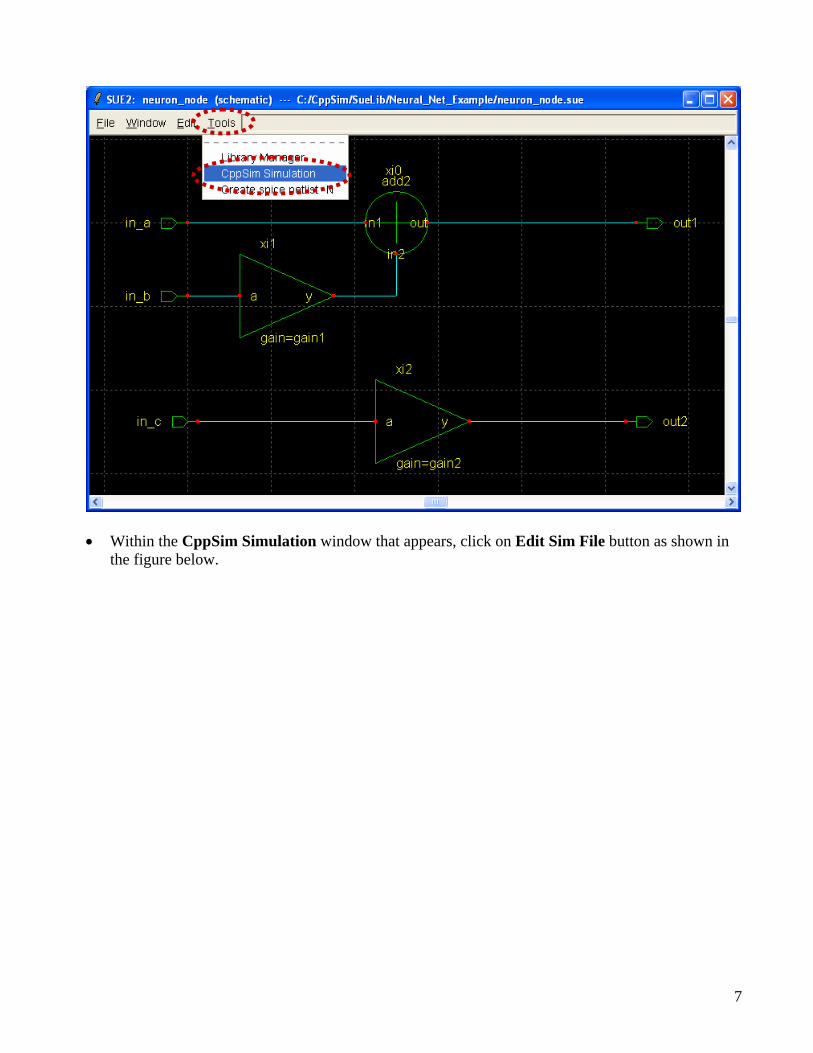
• Within the CppSim Simulation window that appears, click on Edit Sim File button as shown in
the figure below.
7
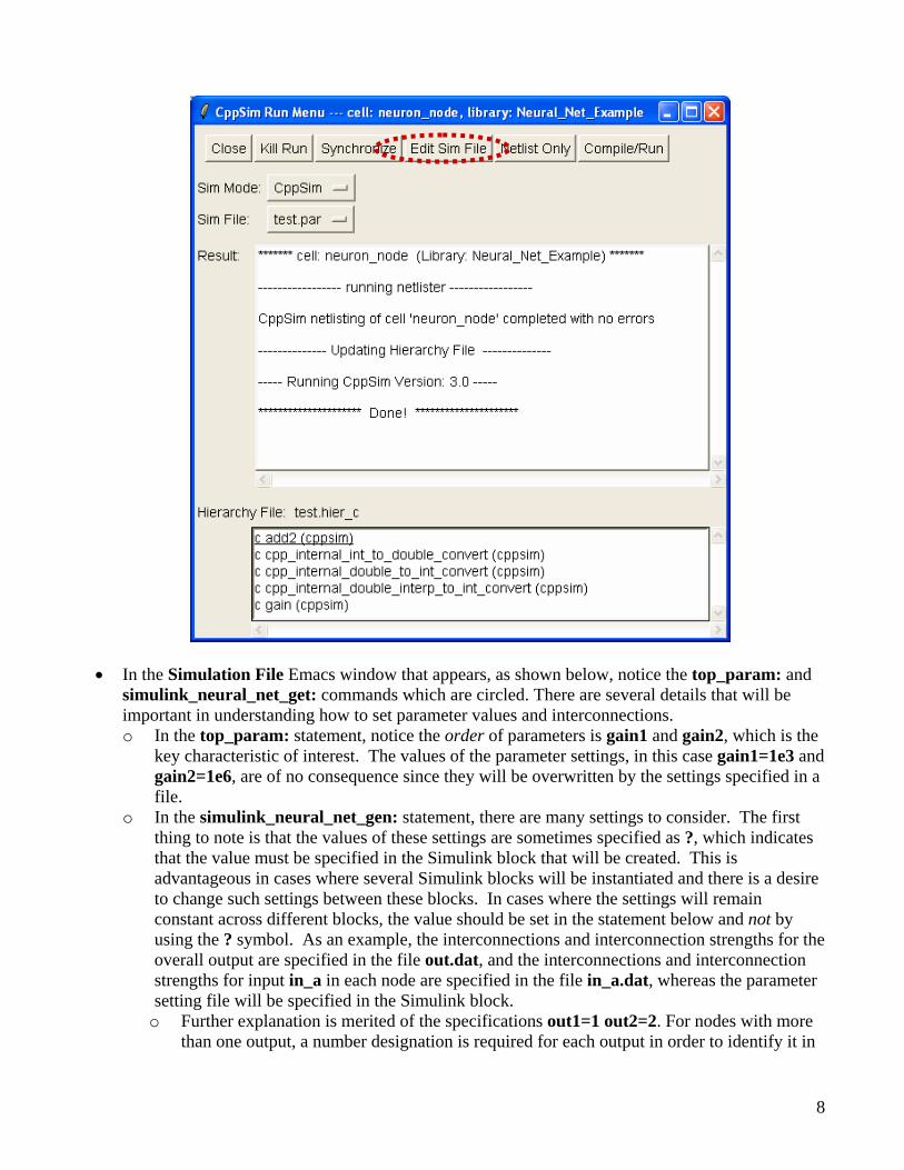
• In the Simulation File Emacs window that appears, as shown below, notice the top_param: and simulink_neural_net_get: commands which are circled. There are several details that will be important in understanding how to set parameter values and interconnections. o In the top_param: statement, notice the order of parameters is gain1 and gain2, which is the
key characteristic of interest. The values of the parameter settings, in this case gain1=1e3 and gain2=1e6, are of no consequence since they will be overwritten by the settings specified in a file.
o In the simulink_neural_net_gen: statement, there are many settings to consider. The first thing to note is that the values of these settings are sometimes specified as ?, which indicates that the value must be specified in the Simulink block that will be created. This is advantageous in cases where several Simulink blocks will be instantiated and there is a desire to change such settings between these blocks. In cases where the settings will remain constant across different blocks, the value should be set in the statement below and not by using the ? symbol. As an example, the interconnections and interconnection strengths for the overall output are specified in the file out.dat, and the interconnections and interconnection strengths for input in_a in each node are specified in the file in_a.dat, whereas the parameter setting file will be specified in the Simulink block.
o Further explanation is merited of the specifications out1=1 out2=2. For nodes with more than one output, a number designation is required for each output in order to identify it in
8
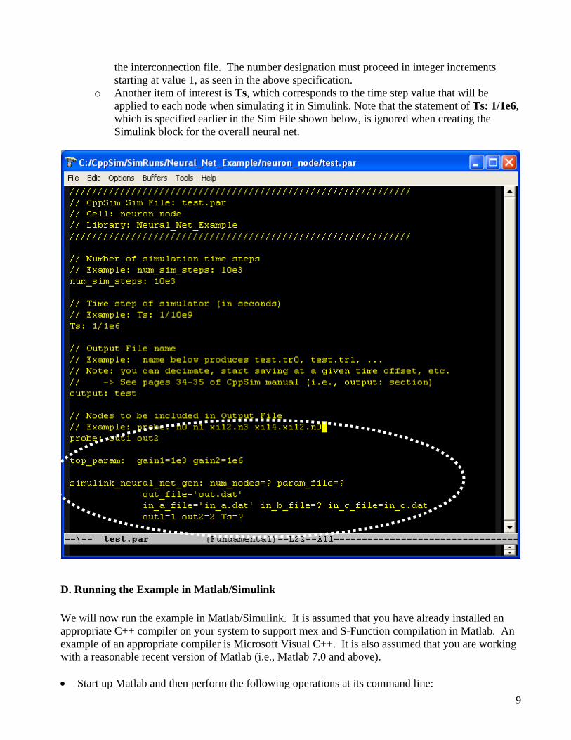
the interconnection file. The number designation must proceed in integer increments starting at value 1, as seen in the above specification.
o Another item of interest is Ts, which corresponds to the time step value that will be applied to each node when simulating it in Simulink. Note that the statement of Ts: 1/1e6, which is specified earlier in the Sim File shown below, is ignored when creating the Simulink block for the overall neural net.
D. Running the Example in Matlab/Simulink We will now run the example in Matlab/Simulink. It is assumed that you have already installed an appropriate C++ compiler on your system to support mex and S-Function compilation in Matlab. An example of an appropriate compiler is Microsoft Visual C++. It is also assumed that you are working with a reasonable recent version of Matlab (i.e., Matlab 7.0 and above). • Start up Matlab and then perform the following operations at its command line: 9
o addpath(‘c:\CppSim\CppSimShared\HspiceToolbox’) o cd c:\CppSim\SimRuns\Neural_Net_Example\neuron_node The first of the above commands adds Matlab commands for running and compiling CppSim blocks within Matlab. The second of the above commands sets the current Matlab directory to the appropriate place to run and compile the cell neuron_node into a neural network that will then be embedded within a corresponding Simulink block. As you work with different base nodes and their corresponding networks, you will need to change this directory. In general, the working directory will be: c:\CppSim\SimRuns\LIBRARY_NAME\CELL_NAME. In this case, LIBRARY_NAME is Neural_Net_Example, and the CELL_NAME is neuron_node.
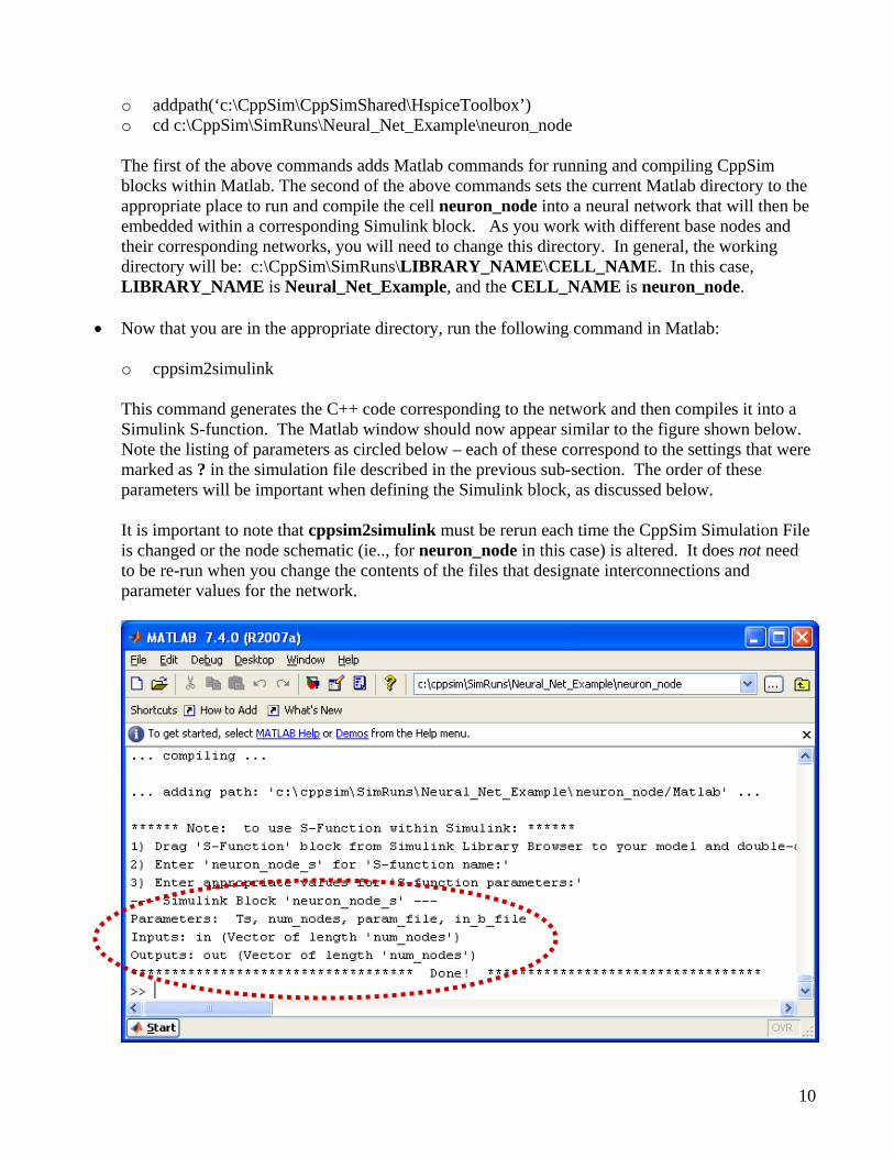
• Now that you are in the appropriate directory, run the following command in Matlab: o cppsim2simulink This command generates the C++ code corresponding to the network and then compiles it into a Simulink S-function. The Matlab window should now appear similar to the figure shown below. Note the listing of parameters as circled below – each of these correspond to the settings that were marked as ? in the simulation file described in the previous sub-section. The order of these parameters will be important when defining the Simulink block, as discussed below. It is important to note that cppsim2simulink must be rerun each time the CppSim Simulation File is changed or the node schematic (ie.., for neuron_node in this case) is altered. It does not need to be re-run when you change the contents of the files that designate interconnections and parameter values for the network.
10
• Now run the following command in Matlab:
o create_tables This command generates files that are used to specify the interconnection of the network. We will discuss this function in further detail in the next section.
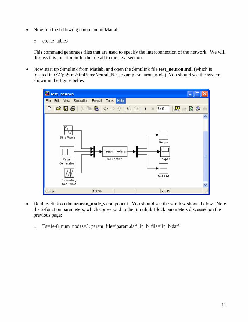
• Now start up Simulink from Matlab, and open the Simulink file test_neuron.mdl (which is located in c:\CppSim\SimRuns\Neural_Net_Example\neuron_node). You should see the system shown in the figure below.
• Double-click on the neuron_node_s component. You should see the window shown below. Note the S-function parameters, which correspond to the Simulink Block parameters discussed on the previous page:
o Ts=1e-8, num_nodes=3, param_file=’param.dat’, in_b_file=’in_b.dat’
11
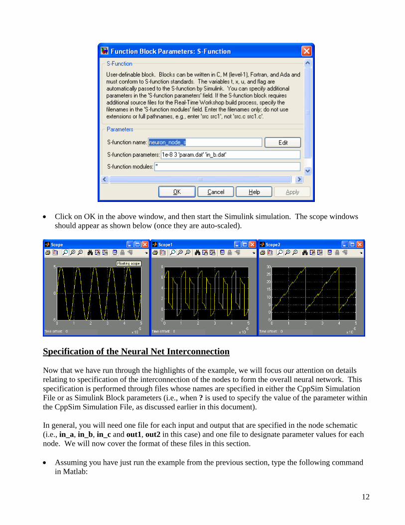
• Click on OK in the above window, and then start the Simulink simulation. The scope windows should appear as shown below (once they are auto-scaled).
Specification of the Neural Net Interconnection Now that we have run through the highlights of the example, we will focus our attention on details relating to specification of the interconnection of the nodes to form the overall neural network. This specification is performed through files whose names are specified in either the CppSim Simulation File or as Simulink Block parameters (i.e., when ? is used to specify the value of the parameter within the CppSim Simulation File, as discussed earlier in this document). In general, you will need one file for each input and output that are specified in the node schematic (i.e., in_a, in_b, in_c and out1, out2 in this case) and one file to designate parameter values for each node. We will now cover the format of these files in this section. • Assuming you have just run the example from the previous section, type the following command
in Matlab:
12

o edit create_tables You should see an edit window similar to what is shown below, which displays the create_tables.m Matlab script.
• In the above Matlab script, you will notice that there are two custom functions that are used throughout the script: save_param_to_file() and save_to_file(). This functions are defined at the end of the script, and simply store the contents of the input matrix to a corresponding ASCII file. For large matrices, one may need to write faster versions of these functions since they are relatively slow in their execution speed. For small matrices as discussed now, these scripts should be sufficient.
• The first matrix that is saved corresponds to the parameters of the node. These parameters are
specified in the top_param: statement of the CppSim Simulation File, as shown on page 8. For this example, recall that this statement was:
o top_param: gain1=1e3 gain2=1e6 As mentioned earlier, the actual values (i.e., 1e3 and 1e6) are ignored, and only the order is of consequence (i.e., gain1, gain2). In examining the Matlab script above, notice that each node is fed two parameter values (i.e., [3 10]). Specifically, given the above top_param: statement, this translates to setting gain1=3, gain2=10 for each node. While each node is fed the same parameter values in this particular example, they can be arbitrarily set for each node in practice.
13
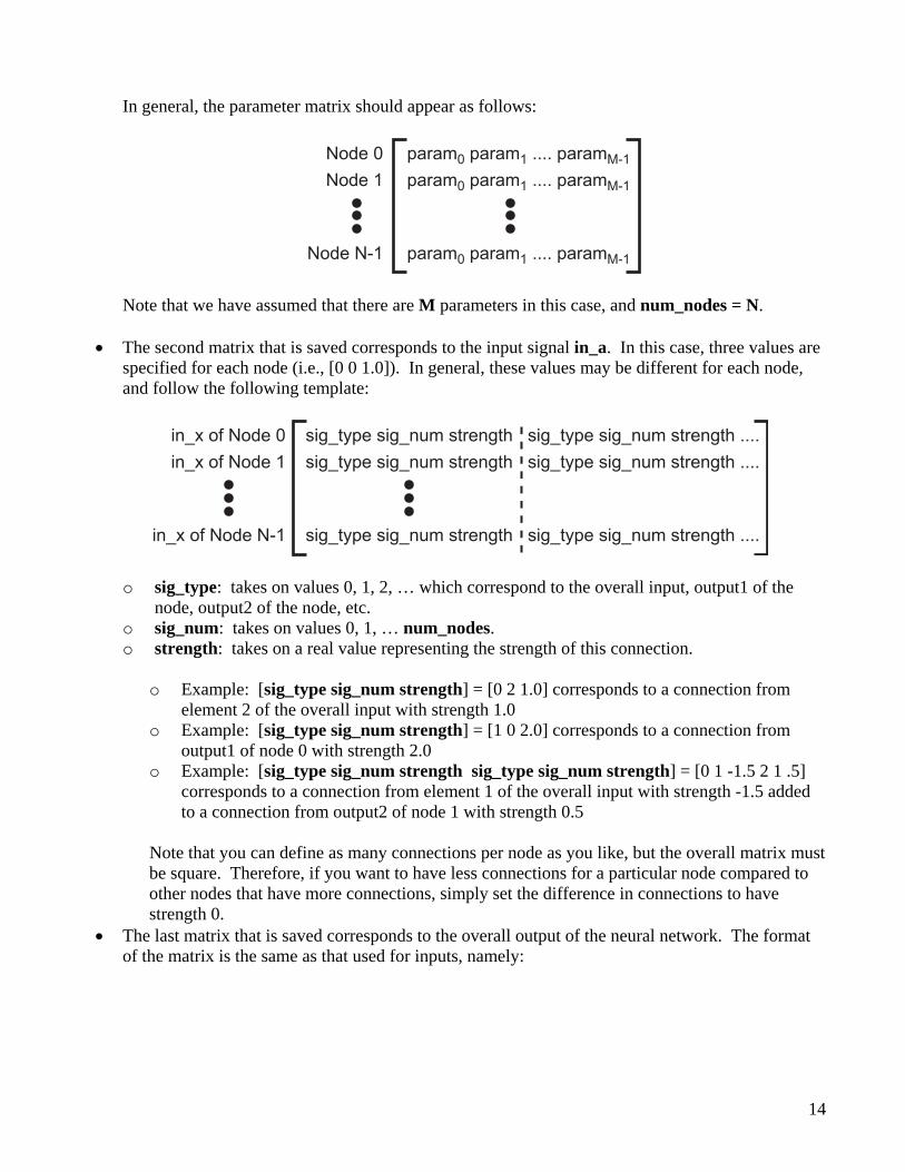
In general, the parameter matrix should appear as follows:
param0 param1 .... paramM-1
param0 param1 .... paramM-1
param0 param1 .... paramM-1
Node 0
Node 1
Node N-1
Note that we have assumed that there are M parameters in this case, and num_nodes = N.
• The second matrix that is saved corresponds to the input signal in_a. In this case, three values are
specified for each node (i.e., [0 0 1.0]). In general, these values may be different for each node, and follow the following template:
sig_type sig_num strength sig_type sig_num strength .... in_x of Node 0
in_x of Node 1
in_x of Node N-1
sig_type sig_num strength sig_type sig_num strength ....
sig_type sig_num strength sig_type sig_num strength ....
o sig_type: takes on values 0, 1, 2, … which correspond to the overall input, output1 of the
node, output2 of the node, etc. o sig_num: takes on values 0, 1, … num_nodes. o strength: takes on a real value representing the strength of this connection.
o Example: [sig_type sig_num strength] = [0 2 1.0] corresponds to a connection from element 2 of the overall input with strength 1.0
o Example: [sig_type sig_num strength] = [1 0 2.0] corresponds to a connection from output1 of node 0 with strength 2.0
o Example: [sig_type sig_num strength sig_type sig_num strength] = [0 1 -1.5 2 1 .5] corresponds to a connection from element 1 of the overall input with strength -1.5 added to a connection from output2 of node 1 with strength 0.5
Note that you can define as many connections per node as you like, but the overall matrix must be square. Therefore, if you want to have less connections for a particular node compared to other nodes that have more connections, simply set the difference in connections to have strength 0.
• The last matrix that is saved corresponds to the overall output of the neural network. The format of the matrix is the same as that used for inputs, namely:
14
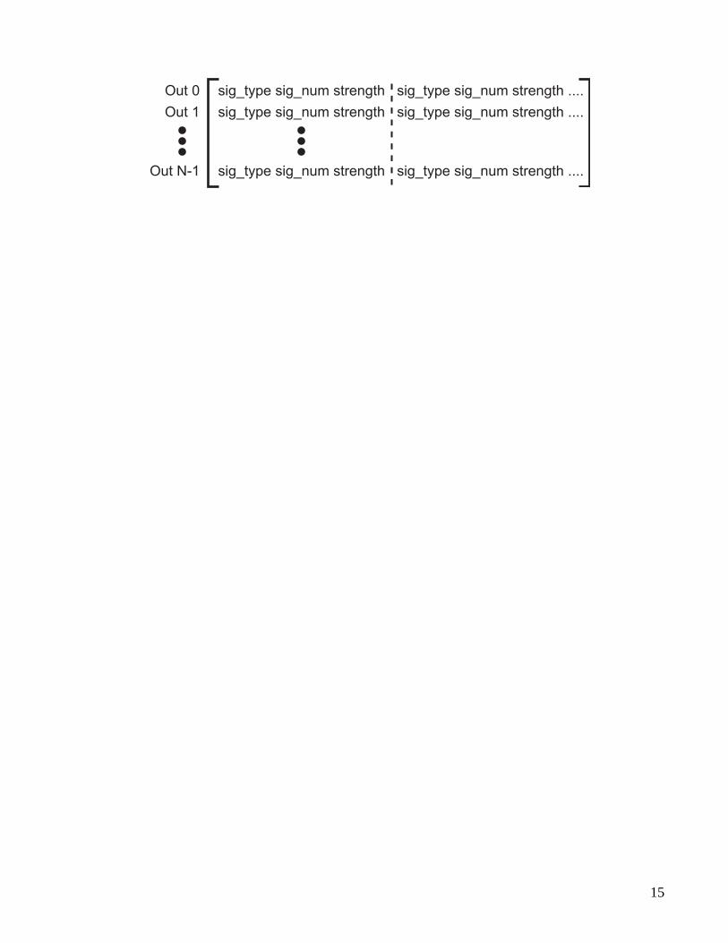
sig_type sig_num strength sig_type sig_num strength .... Out 0
Out 1
Out N-1
sig_type sig_num strength sig_type sig_num strength ....
sig_type sig_num strength sig_type sig_num strength ....
15