using a depth camera for indoor robot localization … · using a depth camera for indoor robot...
TRANSCRIPT

Using a Depth Camera for Indoor Robot Localization and Navigation
Joao Cunha and Eurico Pedrosa and Cristovao Cruz and Antonio J.R. Neves and Nuno Lau
Abstract— Depth cameras are a rich source of information forrobot indoor localization and safe navigation. The recent avail-ability of the low-cost Kinect sensor provides a valid alternativeto other available sensors, namely laser-range finders. Thispaper presents the first results of the application of a Kinectsensor on a wheeled indoor service robot for elderly assistance.The robot makes use of a metric map of the environment’swalls and uses the depth information of the Kinect camera todetect the walls and localize itself in the environment. In ourapproach an error minimization method is used providing real-time efficient robot pose estimation. Furthermore, the depthcamera provides information about the obstacles surroundingthe robot, allowing the application of path-finding algorithmssuch as D* Lite achieving safe and robust navigation. Usingthe proposed solution, we were able to adapt a robotic soccerrobot developed at the University of Aveiro to successfullynavigate in a domestic environment, across different roomswithout colliding with obstacles in the environment.
I. INTRODUCTION
Depth cameras are revolutionizing robot perception as a re-placement for sensors such as laser-range finders and stereo-vision systems. While depth cameras have been availablefor some years, the market price is an hindering factor fortheir application in Robotics. However the easily availableMicrosoft Kinect depth camera provides decent quality depthinformation of the surrounding environment at a highlycompetitive price. This factor makes the Kinect significantlyappealing as is easily demonstrated by its adoption byresearch centers across the globe [1][2].
In this paper we present the application of a Kinectsensor in order to adapt a robotic soccer platform to nav-igate in an indoor unstructured environment. The robotused in this work is a CAMBADA robot. CooperativeAutonomous Mobile roBots with Advanced DistributedArchitecture (CAMBADA) is the robotic soccer team of theUniversity of Aveiro (UA) competing in RoboCup MiddleSize League (MSL). The CAMBADA project started in2003 by researchers of the Transverse Activity on IntelligentRobotics (ATRI) research group within Institute of Elec-tronics and Telematics Engineering of Aveiro (IEETA) andstudents of the Department of Electronics, Telecommunica-tions and Informatics (DETI) from the UA. Since its origin,the CAMBADA team has competed in several national andinternational competitions having won the last five nationalchampionships as well as the 2008 edition of RoboCupWorld Championship. More recently, the CAMBADA teamhas placed in third in both RoboCup 2009 in Graz, Austriaand RoboCup 2010 in Singapore.
Building on the success and experience of the roboticsoccer team, CAMBADA started to pursue challenges indifferent fields of application, namely the development of a
service robot to compete in the RoboCup@Home league1.There is no better proof of the successful application ofsoccer robots in domestic environments than this league.The RoboCup@Home league was created in 2006 from theneed to place more emphasis on real world problems, notaddressed in robotic soccer [3]. This league is currentlythe largest league of the RoboCup initiative and includesa vast number of teams that started as soccer teams and thenevolved to this robotic paradigm.
The remainder of this paper is structured as follows.Section II discusses related work on indoor robot localiza-tion and navigation. The methods applied to extract usefulinformation from the retrieved depth image are presented inSection IV. The used localization algorithm is discussed inSection V. The applied methods for obstacle avoidance andpath-finding are detailed in Section VI. The experimentalresults demonstrating the robustness of the approach arepresented in Section VII. Section VIII draws the conclusionsof the work described in this paper.
II. RELATED WORK
A. Perception
Current work related to environment perception that in-cludes depth sensing is centred around laser range finders andstereo vision systems. These approaches are either accuratebut slow, as in the case of 3D sensing based on laserrange finders [4] or computationally intensive, as in thecase of stereo vision systems [5]. The Kinect depth sensorbrings a fast and relatively high resolution solution for depthsensing, while being considerably cheaper than the referredalternatives [6].
Similar work to the one presented here for wall detectionwas already presented in [7], with the ”Wall without Contra-diction method”. The version used here is a very simplifiedalternative, but the core ideia remains the same, which is thata wall is only a wall if the robot can’t see behind it.
B. Indoor Localization
Mobile robot indoor localization has been referred as “themost fundamental problem to providing a mobile robot withautonomous capabilities” [8].
Robot localization has been subject of active research inthe last decades. All the de facto algorithms share the com-mon characteristic of representing the internal pose belief asa probabilistic distribution [9].
Developed approaches can be roughly divided in two dif-ferent methodologies: Markov and Gaussian Localization or
1www.robocupathome.org

Monte-Carlo Localization. A classical and highly successfulexample of the application of Markov localization is theMinerva museum tour guide robot [10], which successfullynavigated in crowded environments. A famous exampleof Gaussian Localization is based on Kalman filters [11].Kalman filters are an efficient method for robot tracking.However they assume Gaussian noise and linear motionmodels. Extensions to the classic Kalman algorithm suchas the Extended Kalman filter are widely used as they relaxsuch assumptions. Since Kalman filters can only representunimodal probabilistic distribution, a common method is touse Multi-Hypothesis Tracking filter, which represent theinternal belief by a set of Gaussians.
Another well established approach is the application ofparticle filters combined with motion models, also known asMonte Carlo Localization [12][13]. The inner belief is rep-resented as a set of particles (hypothesis) that are randomlysampled over the environment. Although more recent thanother approaches, Monte Carlo Localization has become oneof the most popular localization algorithms in robotics. Thisis usually attributed to the fact that Monte-Carlo Localizationcan approximate any probabilistic distribution, such as com-plex multimodal distributions. This is an obvious advantagein the presence of ambiguous indistinct topologies.
C. Robotic Navigation
In robotics, certain tasks requires the robot to navigatein indoor environment. Traditionally the environment isassumed to be static and all objects rigid [14]. A deliberativeapproach in this type of environments is, for example, celldecomposition [15] with A* for shortest path computation.However, an indoor environment has an intrinsic uncertaintyand complexity that can not be overcome with this approach.As alternative, a reactive approach responds to the sensorsstimuli to generate an adequate behavior. An example isthe use of potential field methods (PFM) for local planninglike obstacle avoidance [16]. Nevertheless, local minima isa best-known problem in reactive navigation such as PFM[17]. The local minima problem can be solved by detectingthe trap-situation and recalculate the navigation plan withthe new information [17].
Another common practice it to combine global pathplanning with local path planning, such as [18], for fastincremental path planning. Initially, it calculates the shortestpath between two points and, as it navigates the unknown,adjusts the path plan accordingly the perceived environment.As consequence, obstacle avoidance results naturally fromthe incremental path planning.
III. SYSTEM ARCHITECTURE
The robotic platform used is based on the CAMBADArobotic soccer platform. The robot has a conical base withradius of 24 cm and height of 80 cm. The physical structureis built on a modular approach with three main modules orlayers.
The top layer has the robot vision system. Currently therobot uses a single Microsoft Kinect camera placed on top
of the robot pointing forwards. This is the main sensor ofthe robot. The retrieved information is used for localizationand path-planning to predefined goals.
The middle layer houses the processing unit, currentlya 13” laptop, which collects data from the sensors andcomputes the commands to the actuators. The laptop executesthe vision software along with all high level and decisionsoftware and can be seen as the brain of the robot. Beneaththe middle layer, a network of micro-controllers is placed tocontrol the low-level sensing/actuation system, or the nervoussystem of the robot. The sensing and actuation system ishighly distributed, using the CAN protocol, meaning thenodes in the network control different functions of the robot,such as motion, odometry and system monitoring.
Finally, the lowest layer is composed of the robot motionsystem. The robot moves with the aid of a set of threeomni-wheels, disposed at the periphery of the robot atangles that differ 120 degrees from each other, powered bythree 24V/150W Maxon motors (Figure 1). With this wheelconfiguration, the robot is capable of holonomic motion,being able to move in a given direction independently ofits orientation.
a) b)Fig. 1. CAMBADA hardware system: a) The robot platform. b) Detailedview of the motion system.
Following the CAMBADA hardware approach, the soft-ware is also distributed. Therefore, five different processesare executed concurrently. All the processes run at the robot’sprocessing unit in Linux.
Inter-process communication is handled by means of aRealTime DataBase (RTDB) [19] which is physically im-plemented in shared memory. The RTDB is divided in tworegions, the local and shared regions. The local section allowscommunication between processes running in the robot.The shared section implements a Blackboard communica-tion paradigm and allows communication between processesrunning in different robots. All shared sections in the RTDBare kept updated by an adaptive broadcasting mechanism thatminimizes delay and packet collisions.
The processes composing the CAMBADA software are(Figure 2):
• Vision which is responsible for acquiring the visual datafrom the Kinect sensor.
• Agent is the process that integrates the sensor infor-mation and constructs the robot’s worldstate. The agent

then decides the commands to be applied, based on theperception of the worldstate.
• Comm handles the inter-robot communication, receiv-ing the information shared by other robots and trans-mitting the data from the shared section of the RTDB.
• HWcomm or hardware communication process is re-sponsible for transmitting the data to and from the low-level sensing and actuation system.
• Monitor that checks the state of the remaining pro-cesses, relaunching them in case of abnormal termina-tion.
Given the real-time constraints of the system, all processscheduling is handled by a library specifically developed forthe task, the Process Manager [20].
Low-level control layerOdometry
System Monitor
Coordination Layer
Monitor
Proc
ess
Man
ager
Sensorial interpretation
Intelligence and Coordination
Vision
Low-level communication
handler
RTDB
Wireless Communication
Motion
Fig. 2. CAMBADA software architecture.
A. Monitoring station
The monitoring station, also known as basestation, hasa determinant role both during the development of anautonomous assistant robot capability as well during itsapplication. The basestation is an adapted version of theCAMBADA team basestation [21] taking in considerationa set of requirements that emerge from the development ofa service and assistive robot (Figure 3).
Fig. 3. CAMBADA basestation GUI. The GUI is divided in three panes.The lower pane shows the internal state of the robots. The center pane drawsthe indoor blueprint and the robots location. The right pane hold the robotscontrol panel box (e.g. start, stop) and several operational visual flags.
The basestation application provides a set of tools toperform the control and monitoring of the robot. Regardingthe control activity, this application allows high level controlof the robot by sending basic commands such as run, stopand docking. It also provides a high level monitoring of therobot internal state, namely its batteries status, current roleand behavior, indoor self-localization, current destinationpoint, breadcrumb trail, etc.
Furthermore, this application provides a mechanism thatcan be used to enforce a specific behavior of the robot, fordebugging purposes.
IV. VISUAL PERCEPTION
Humans rely heavily on vision or vision based abstractionsto acknowledge the world, to think about the world and tomanipulate the world. It is only logical to empower artificialagents with a vision systems with capabilities similar to thehuman vision system.
The vision subsystem of this robot is constituted by asingle depth sensor, the Kinect, fixed at the top of therobot. It is accessed through the freenect [22] library, andprovides a depth and color view of the world. With thedepth information, we create a 3D metric model of theenvironment. Using this model, we then extract relevantenvironment features for the purpose of localization andnavigation, namely the walls and the obstacles, The proposedmethods consider that the height and pitch of the camerarelatively to the ground plane remain constant, parametersthat are set when the system is calibrated.
x
y
z
Fig. 4. Camera coordinate system
A. Pre-Processing
Both wall and obstacle detection is done using only thedepth image, which has 640 × 480 pixels. The image issubsampled by a factor of 5 in both dimensions, leaving uswith a 128×96 image, which has proven to contain sufficientinformation for wall and obstacle detection. This decisionis not based on current time constraints, but was made toaccount for future project developments.
B. Walls
A wall is a structure that delimits rooms. It is opaque andconnects the floor to the ceiling.
With this simple definition in mind, the approach wefollow to identify the walls in the environment is to selectall the points with height, relative to the floor, lower than

the ceiling height and perform a column-wise search onthe remaining points of the image for the point which isfarthest from the robot, or, according the the coordinatesystem shown in Figure 4, the one that has the greatest xcomponent. This leaves us with 128 possible wall points.
The retrieved points are then used in later stages ofprocessing to allow for robot localization.
C. Obstacles
An obstacle is an occupied volume with which the robotcan collide.
The obstacle detection method is similar to the one usedfor wall detection. To detect the obstacles, we reject thepoints that have an height, relative to the floor, greater thanthe robot height and that do not lie on the floor. An heightthreshold is used to detect if the point lies on the floor,method that proved to be good enough to cope with the noise.We than perform a column-wise search on the remainingpoints of the image for the point closest to the robot, with asmaller x.
At the end of this process we have 128 obstacle pointsthat can be used for occupancy belief update.
V. INDOOR LOCALIZATION
For indoor localization, we successfully adapted the local-ization algorithm used by the CAMBADA team to estimatea robot position in a robotic soccer field. The algorithm wasinitially proposed by the MSL team Brainstormers Tribots[23].
The Tribots algorithm [23] constructs a FieldLUT fromthe soccer field. A FieldLUT is a grid-like data structurewhere the value of each cell is the distance to the closestfield line. The gradient of the FieldLUT values representsthe direction to the closest field line. The robot detects therelative position of the field line points through vision andtries to match the seen points with the soccer field map,represented by the FieldLUT. Given a trial position, basedon the previous estimate and odometry, the robot calculatesthe matching error and its gradient and improves the trialposition by performing an error minimization method basedon gradient descent and the RPROP algorithm [24]. Afterthis optimization process the robot pose is integrated withthe odometry data in a Kalman Filter for a refined estimationof the robot pose.
To apply the aforementioned algorithm in a indoor en-vironment the concept of white line was replaced with thewalls. In an initial phase, given a map of the environment,usually the building blueprints, a FieldLUT list is created thatcontains all possible configurations of seen walls for differentpositions (Algorithm 1). By testing a grid of points over themap, a new FieldLUT is created, and added to the FieldLUTlist, when a new configuration of seen walls is detected. Asthe robot moves through the environment, it dynamicallyloads the FieldLUT corresponding to its position, whichshould consist of the walls seen in that part of the map.
The need to use a set of FieldLUTs instead of a singleFieldLUT for the entire map arises from the local minimum
problem inherent to gradient descent algorithms. Since thewalls in a domestic environment have an associated heightwhich is naturally higher than the robot, from a given pointin the environment there is usually a set of walls that are outof the line-of-sight of the robot. This scenario doesn’t occurin a robotic soccer field where the lines are co-planar withthe field. Therefore using a single FieldLUT could matchthe wall points extracted from the captured images to unseenwalls, resulting in erroneous self-localization.
The described method does not solve the initial localiza-tion problem. This is solved by applying the visual optimiza-tion process on different trial positions evenly spaced overthe known map. To reduce the search space of the initiallocalization, the initial heading of the robot is given by adigital compass.
Algorithm 1 Build FieldLUTsInput: map
wallList← ∅fieldLUT list← ∅mapping ← ∅pointList← map.generateGrid()for all point in pointList dovisibleWalls← map.findV isibleWalls(point)if not wallList.find(visibleWalls) then
wallList.add(visibleWalls)fieldLUT ← buildF ieldLUT (visibleWalls)fieldLUT list.add(fieldLUT )
end ifmapping.add(< point, fieldLUT.id >)
end forreturn < fieldLUT list,mapping >
VI. GOAL DIRECTED NAVIGATION
The robotic agent receives a sequence of goal points togo to in a patrolling manner. As it arrives the goal point itdecomposes its path to the next goal point in intermediategoal points. The robot navigates between intermediate goalpoints in a straight line.
The considered metric map is a discrete two-dimensionaloccupancy grid. Each cell-grid (x, y) has an associated valuethat yields the believed occupancy. The navigation plan iscalculated by a path-finding algorithm supported by theprobabilistic occupancy map of the environment. Becauseof the dynamic nature of the environment the robotic agentuses D* Lite [25], an incremental path-finding algorithm thatavoids full re-planning in face of changes in the environment.This methodology enables obstacle avoidance seldom basedon incremental path planning (Figure 5).
The environment is represented in an occupancy map im-plemented by the OctoMap library [26]. Although OctoMapis capable of creating 3D occupancy maps, the environmentis projected onto the ground plane, thus constructing a 2Doccupancy map of the environment. Each change in theenvironment, tracked by the occupancy map, is reflected in
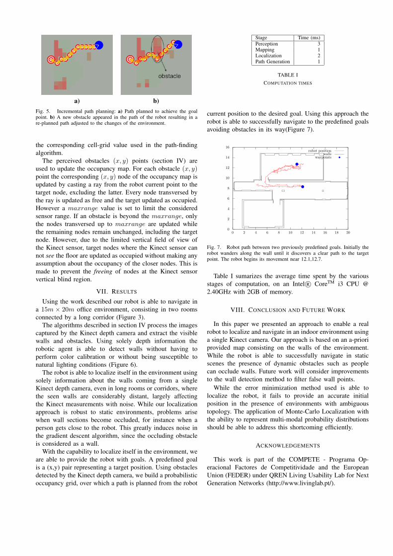
a) b)Fig. 5. Incremental path planning: a) Path planned to achieve the goalpoint. b) A new obstacle appeared in the path of the robot resulting in are-planned path adjusted to the changes of the environment.
the corresponding cell-grid value used in the path-findingalgorithm.
The perceived obstacles (x, y) points (section IV) areused to update the occupancy map. For each obstacle (x, y)point the corresponding (x, y) node of the occupancy map isupdated by casting a ray from the robot current point to thetarget node, excluding the latter. Every node transversed bythe ray is updated as free and the target updated as occupied.However a maxrange value is set to limit the consideredsensor range. If an obstacle is beyond the maxrange, onlythe nodes transversed up to maxrange are updated whilethe remaining nodes remain unchanged, including the targetnode. However, due to the limited vertical field of view ofthe Kinect sensor, target nodes where the Kinect sensor cannot see the floor are updated as occupied without making anyassumption about the occupancy of the closer nodes. This ismade to prevent the freeing of nodes at the Kinect sensorvertical blind region.
VII. RESULTS
Using the work described our robot is able to navigate ina 15m × 20m office environment, consisting in two roomsconnected by a long corridor (Figure 3).
The algorithms described in section IV process the imagescaptured by the Kinect depth camera and extract the visiblewalls and obstacles. Using solely depth information therobotic agent is able to detect walls without having toperform color calibration or without being susceptible tonatural lighting conditions (Figure 6).
The robot is able to localize itself in the environment usingsolely information about the walls coming from a singleKinect depth camera, even in long rooms or corridors, wherethe seen walls are considerably distant, largely affectingthe Kinect measurements with noise. While our localizationapproach is robust to static environments, problems arisewhen wall sections become occluded, for instance when aperson gets close to the robot. This greatly induces noise inthe gradient descent algorithm, since the occluding obstacleis considered as a wall.
With the capability to localize itself in the environment, weare able to provide the robot with goals. A predefined goalis a (x,y) pair representing a target position. Using obstaclesdetected by the Kinect depth camera, we build a probabilisticoccupancy grid, over which a path is planned from the robot
Stage Time (ms)Perception 3Mapping 1Localization 2Path Generation 1
TABLE ICOMPUTATION TIMES
current position to the desired goal. Using this approach therobot is able to successfully navigate to the predefined goalsavoiding obstacles in its way(Figure 7).
0
2
4
6
8
10
12
14
16
0 2 4 6 8 10 12 14 16 18 20
robot positionwalls
waypoints
Fig. 7. Robot path between two previously predefined goals. Initially therobot wanders along the wall until it discovers a clear path to the targetpoint. The robot begins its movement near 12.1,12.7.
Table I sumarizes the average time spent by the variousstages of computation, on an Intel R© CoreTM i3 CPU @2.40GHz with 2GB of memory.
VIII. CONCLUSION AND FUTURE WORK
In this paper we presented an approach to enable a realrobot to localize and navigate in an indoor environment usinga single Kinect camera. Our approach is based on an a-prioriprovided map consisting on the walls of the environment.While the robot is able to successfully navigate in staticscenes the presence of dynamic obstacles such as peoplecan occlude walls. Future work will consider improvementsto the wall detection method to filter false wall points.
While the error minimization method used is able tolocalize the robot, it fails to provide an accurate initialposition in the presence of environments with ambiguoustopology. The application of Monte-Carlo Localization withthe ability to represent multi-modal probability distributionsshould be able to address this shortcoming efficiently.
ACKNOWLEDGEMENTS
This work is part of the COMPETE - Programa Op-eracional Factores de Competitividade and the EuropeanUnion (FEDER) under QREN Living Usability Lab for NextGeneration Networks (http://www.livinglab.pt/).
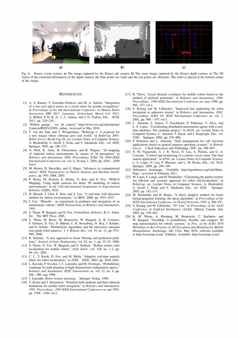
a) b) c)Fig. 6. Kinect vision system: a) The image captured by the Kinect rgb camera. b) The same image captured by the Kinect depth camera. c) The 2Dvision of the extracted information of the depth camera, the blue points are walls and the red points are obstacles. The robot is placed in the bottom centerof the image.
REFERENCES
[1] A. A. Ramey, V. Gonzalez-Pacheco, and M. A. Salichs, “Integrationof a low-cost rgb-d sensor in a social robot for gesture recognition,”in Proceedings of the 6th International Conference on Human RobotInteraction, HRI 2011, Lausanne, Switzerland, March 6-9, 2011,A. Billard, P. H. K. Jr., J. A. Adams, and J. G. Trafton, Eds. ACM,2011, pp. 229–230.
[2] “Willow garage - ros 3d contest,” http://www.ros.org/wiki/openni/Contests/ROS%203D/, online, Accessed in May 2010.
[3] T. van der Zant and T. Wisspeintner, “Robocup x: A proposal fora new league where robocup goes real world,” in RoboCup 2005:Robot Soccer World Cup IX, ser. Lecture Notes in Computer Science,A. Bredenfeld, A. Jacoff, I. Noda, and Y. Takahashi, Eds., vol. 4020.Springer, 2005, pp. 166–172.
[4] O. Wulf, K. Arras, H. Christensen, and B. Wagner, “2d mappingof cluttered indoor environments by means of 3d perception,” inRobotics and Automation, 2004. Proceedings. ICRA ’04. 2004 IEEEInternational Conference on, vol. 4, 26-may 1, 2004, pp. 4204 – 4209Vol.4.
[5] M. Brown, D. Burschka, and G. Hager, “Advances in computationalstereo,” IEEE Transactions on Pattern Analysis and Machine Intelli-gence, pp. 993–1008, 2003.
[6] P. Henry, M. Krainin, E. Herbst, X. Ren, and D. Fox, “RGB-DMapping: Using depth cameras for dense 3D modeling of indoorenvironments,” in the 12th International Symposium on ExperimentalRobotics (ISER), 2010.
[7] H. Moradi, J. Choi, E. Kim, and S. Lee, “A real-time wall detectionmethod for indoor environments,” in IROS, 2006, pp. 4551–4557.
[8] I. Cox, “Blanche - an experiment in guidance and navigation of anautonomous vehicle,” IEEE Transactions on Robotics and Automation,1991.
[9] S. Thrun, W. Burgard, and D. Fox, Probabilistic Robotics, R. C. Arkin,Ed. The MIT Press, 2005.
[10] S. Thrun, M. Beetz, M. Bennewitz, W. Burgard, A. B. Cremers,F. Dellaert, D. Fox, D. Hahnel, C. R. Rosenberg, N. Roy, J. Schulte,and D. Schulz, “Probabilistic algorithms and the interactive museumtour-guide robot minerva,” I. J. Robotic Res., vol. 19, no. 11, pp. 972–999, 2000.
[11] R. Kalman, “A new approach to linear filtering and prediction prob-lems,” Journal of basic Engineering, vol. 82, no. 1, pp. 35–45, 1960.
[12] S. Thrun, D. Fox, W. Burgard, and F. Dellaert, “Robust monte carlolocalization for mobile robots,” Artif. Intell., vol. 128, no. 1-2, pp.99–141, 2001.
[13] C. C. T. Kwok, D. Fox, and M. Meila, “Adaptive real-time particlefilters for robot localization,” in ICRA. IEEE, 2003, pp. 2836–2841.
[14] L. Kavraki, P. Svestka, J.-C. Latombe, and M. Overmars, “Probabilisticroadmaps for path planning in high-dimensional configuration spaces,”Robotics and Automation, IEEE Transactions on, vol. 12, no. 4, pp.566 –580, aug 1996.
[15] J. Latombe, Robot motion planning. Springer Verlag, 1990.[16] Y. Koren and J. Borenstein, “Potential field methods and their inherent
limitations for mobile robot navigation,” in Robotics and Automation,1991. Proceedings., 1991 IEEE International Conference on, apr 1991,pp. 1398 –1404 vol.2.
[17] R. Tilove, “Local obstacle avoidance for mobile robots based on themethod of artificial potentials,” in Robotics and Automation, 1990.Proceedings., 1990 IEEE International Conference on, may 1990, pp.566 –571 vol.1.
[18] S. Koenig and M. Likhachev, “Improved fast replanning for robotnavigation in unknown terrain,” in Robotics and Automation, 2002.Proceedings. ICRA ’02. IEEE International Conference on, vol. 1,2002, pp. 968 – 975 vol.1.
[19] L. Almeida, F. Santos, T. Facchinetti, P. Pedreiras, V. Silva, andL. S. Lopes, “Coordinating distributed autonomous agents with a real-time database: The cambada project,” in ISCIS, ser. Lecture Notes inComputer Science, C. Aykanat, T. Dayar, and I. Korpeoglu, Eds., vol.3280. Springer, 2004, pp. 876–886.
[20] P. Pedreiras and L. Almeida, “Task management for soft real-timeapplications based on general purpose operating systems,” in RoboticSoccer. I-Tech Education and Publishing, 2007, pp. 598–607.
[21] N. M. Figueiredo, A. J. R. Neves, N. Lau, A. Pereira, and G. A.Corrente, “Control and monitoring of a robotic soccer team: The basestation application,” in EPIA, ser. Lecture Notes in Computer Science,L. S. Lopes, N. Lau, P. Mariano, and L. M. Rocha, Eds., vol. 5816.Springer, 2009, pp. 299–309.
[22] libfreenect homepage, “Available http://openkinect.org/wiki/MainPage,” accessed in February 2011.
[23] M. Lauer, S. Lange, and M. Riedmiller, “Calculating the perfect match:An efficient and accurate approach for robot self-localization,” inRoboCup, ser. Lecture Notes in Computer Science, A. Bredenfeld,A. Jacoff, I. Noda, and Y. Takahashi, Eds., vol. 4020. Springer,2005, pp. 142–153.
[24] M. Riedmiller and H. Braun, “A direct adaptive method for fasterbackpropagation learning: the rprop algorithm,” in Proceedings of theIEEE International Conference on Neural Networks, 1993, p. 586–591.
[25] S. Koenig and M. Likhachev, “D* Lite,” in Proceedings of the AAAIConference of Artificial Intelligence (AAAI), Alberta, Canada, July2002, pp. 476–483.
[26] K. M. Wurm, A. Hornung, M. Bennewitz, C. Stachniss, andW. Burgard, “OctoMap: A probabilistic, flexible, and compact 3Dmap representation for robotic systems,” in Proc. of the ICRA 2010Workshop on Best Practice in 3D Perception and Modeling for MobileManipulation, Anchorage, AK, USA, May 2010, software availableat http://octomap.sf.net/. [Online]. Available: http://octomap.sf.net/