user’s manual flir exx series · 12 configuring wi-fi ... #t559845; r. aj/37554/37554; en-us vi....
TRANSCRIPT
User’s manualFLIR Exx series


User’s manualFLIR Exx series
#T559845; r. AJ/37554/37554; en-US iii

Table of contents
1 Disclaimers ........................................................................................11.1 Legal disclaimer .........................................................................11.2 Usage statistics ..........................................................................11.3 Changes to registry .....................................................................11.4 U.S. Government Regulations........................................................11.5 Copyright ..................................................................................11.6 Quality assurance .......................................................................11.7 Patents .....................................................................................11.8 EULATerms ..............................................................................11.9 EULATerms ..............................................................................2
2 Safety information ...............................................................................33 Notice to user .....................................................................................7
3.1 User-to-user forums ....................................................................73.2 Calibration.................................................................................73.3 Accuracy ..................................................................................73.4 Disposal of electronic waste ..........................................................73.5 Training ....................................................................................73.6 Documentation updates ...............................................................73.7 Important note about this manual....................................................73.8 Note about authoritative versions....................................................8
4 Customer help ....................................................................................94.1 General ....................................................................................94.2 Submitting a question ..................................................................94.3 Downloads .............................................................................. 10
5 Quick Start Guide .............................................................................. 115.1 Procedure ............................................................................... 11
6 List of accessories and services ......................................................... 127 Camera parts .................................................................................... 14
7.1 View from the right .................................................................... 147.1.1 Figure.......................................................................... 147.1.2 Explanation................................................................... 14
7.2 View from the left ...................................................................... 157.2.1 Figure.......................................................................... 157.2.2 Explanation................................................................... 15
7.3 LCD and keypad....................................................................... 167.3.1 Figure.......................................................................... 167.3.2 Explanation................................................................... 16
7.4 View from the bottom................................................................. 177.4.1 Figure.......................................................................... 177.4.2 Explanation................................................................... 17
7.5 Battery condition LED indicator .................................................... 187.5.1 Figure.......................................................................... 187.5.2 Explanation................................................................... 18
7.6 Laser pointer ........................................................................... 197.6.1 Figure.......................................................................... 197.6.2 Laser warning label......................................................... 197.6.3 Laser rules and regulations .............................................. 19
8 Screen elements ............................................................................... 208.1 Figure .................................................................................... 20
#T559845; r. AJ/37554/37554; en-US v
Table of contents
8.2 Explanation ............................................................................. 209 Navigating the menu system............................................................... 21
9.1 Figure .................................................................................... 219.2 Explanation ............................................................................. 21
10 Connecting external devices and storage media ................................... 2210.1 Figure .................................................................................... 2210.2 Explanation ............................................................................. 2210.3 Figure .................................................................................... 2310.4 Explanation ............................................................................. 23
11 Pairing Bluetooth devices................................................................... 2411.1 General .................................................................................. 2411.2 Procedure ............................................................................... 24
12 Configuring Wi-Fi .............................................................................. 2512.1 General .................................................................................. 2512.2 Setting up a peer-to-peer connection (most common use) ................. 2512.3 Connecting the camera to a wireless local area network (less
common use)........................................................................... 2513 Handling the camera.......................................................................... 26
13.1 Charging the battery .................................................................. 2613.1.1 Using the power supply to charge the battery ....................... 2613.1.2 Using the stand-alone battery charger to charge the
battery ......................................................................... 2613.2 Turning on and turning off the camera............................................ 2613.3 Adjusting the infrared camera focus .............................................. 27
13.3.1 Figure.......................................................................... 2713.3.2 Procedure .................................................................... 27
13.4 Operating the laser pointer.......................................................... 2813.4.1 Figure.......................................................................... 2813.4.2 Procedure .................................................................... 28
13.5 Removing the battery................................................................. 2813.6 Mounting an accessory lens ........................................................ 2913.7 Calibrating the touchscreen......................................................... 30
13.7.1 Figure.......................................................................... 3013.7.2 Procedure .................................................................... 30
13.8 Using the camera lamp .............................................................. 3113.8.1 General........................................................................ 3113.8.2 Procedure .................................................................... 31
14 Working with images.......................................................................... 3214.1 Saving an image....................................................................... 32
14.1.1 General........................................................................ 3214.1.2 Image capacity .............................................................. 3214.1.3 Naming convention......................................................... 3214.1.4 Procedure .................................................................... 32
14.2 Previewing an image ................................................................. 3214.2.1 General........................................................................ 3214.2.2 Procedure .................................................................... 32
14.3 Opening a saved image.............................................................. 3314.3.1 General........................................................................ 3314.3.2 Procedure .................................................................... 33
14.4 Editing a saved image................................................................ 33
#T559845; r. AJ/37554/37554; en-US vi
Table of contents
14.4.1 General........................................................................ 3314.4.2 Procedure .................................................................... 33
14.5 Adjusting an infrared image......................................................... 3414.5.1 General........................................................................ 3414.5.2 Example 1 .................................................................... 3414.5.3 Example 2 .................................................................... 3414.5.4 Manual adjustment in Level / spanmode ............................. 3514.5.5 Manual adjustment in Level / max / min mode....................... 35
14.6 Performing a non-uniformity correction (NUC) ................................. 3614.6.1 What is a non-uniformity correction?................................... 3614.6.2 When to perform a non-uniformity correction? ...................... 3614.6.3 Procedure .................................................................... 36
14.7 Changing the temperature range .................................................. 3614.7.1 General........................................................................ 3614.7.2 Procedure .................................................................... 36
14.8 Changing the color palette .......................................................... 3614.8.1 General........................................................................ 3614.8.2 Procedure .................................................................... 36
14.9 Zooming in on an image ............................................................. 3714.9.1 General........................................................................ 3714.9.2 Procedure .................................................................... 37
14.10 Deleting an image ..................................................................... 3714.10.1 Procedure .................................................................... 37
14.11 Deleting all images.................................................................... 3714.11.1 Procedure .................................................................... 37
15 Working with image modes................................................................. 3815.1 General .................................................................................. 3815.2 Types of image modes ............................................................... 3815.3 Procedure ............................................................................... 39
16 Working with measurement tools ........................................................ 4016.1 Laying out measurement tools in live mode..................................... 40
16.1.1 General........................................................................ 4016.1.2 Procedure .................................................................... 40
16.2 Laying out measurement tools in edit mode .................................... 4016.2.1 General........................................................................ 4016.2.2 Procedure .................................................................... 40
16.3 Moving and resizing measurement tools ........................................ 4116.3.1 General........................................................................ 4116.3.2 Procedure .................................................................... 41
16.4 Displaying maximum, minimum, and average values ........................ 4116.4.1 General........................................................................ 4116.4.2 Procedure .................................................................... 41
16.5 Setting local measurement parameters for a measurementtool ........................................................................................ 4216.5.1 General........................................................................ 4216.5.2 Procedure .................................................................... 42
17 Working with alarms .......................................................................... 4317.1 Working with color alarms ........................................................... 43
17.1.1 General........................................................................ 4317.1.2 Procedure .................................................................... 43
#T559845; r. AJ/37554/37554; en-US vii
Table of contents
17.2 Working with insulation alarms..................................................... 4317.2.1 General........................................................................ 4317.2.2 Procedure .................................................................... 43
17.3 Working with condensation alarms................................................ 4417.3.1 General........................................................................ 4417.3.2 Procedure .................................................................... 44
18 Fetching data from external FLIR meters .............................................. 4518.1 General .................................................................................. 4518.2 Supported meters ..................................................................... 4518.3 Technical support for external meters ............................................ 4518.4 Procedure ............................................................................... 4518.5 Typical moisture measurement and documentation procedure ............ 45
18.5.1 General........................................................................ 4518.5.2 Procedure .................................................................... 45
19 Annotating images ............................................................................ 4719.1 General .................................................................................. 4719.2 Adding a note .......................................................................... 47
19.2.1 General........................................................................ 4719.2.2 Procedure .................................................................... 47
19.3 Adding a table.......................................................................... 4719.3.1 General........................................................................ 4719.3.2 Procedure .................................................................... 48
19.4 Adding a voice annotation........................................................... 4819.4.1 General........................................................................ 4819.4.2 Procedure .................................................................... 48
20 Recording video clips ........................................................................ 4920.1 General .................................................................................. 4920.2 Procedure: Recording a video clip ................................................ 4920.3 Procedure: Playing a video clip .................................................... 49
21 Screening alarm ................................................................................ 5021.1 General .................................................................................. 5021.2 Procedure ............................................................................... 50
22 Changing settings ............................................................................. 5222.1 General .................................................................................. 5222.2 Procedure ............................................................................... 5222.3 Description of the various settings ................................................ 52
22.3.1 Measurement parameters ................................................ 5222.3.2 Save options ................................................................. 5322.3.3 Add-on lens .................................................................. 5322.3.4 Device settings .............................................................. 53
23 Technical data................................................................................... 5623.1 Online field-of-view calculator ...................................................... 5623.2 Note about technical data ........................................................... 5623.3 Note about authoritative versions.................................................. 5623.4 FLIR E33 ................................................................................ 5723.5 FLIR E40 ................................................................................ 6223.6 FLIR E40 (incl. Wi-Fi)................................................................. 6723.7 FLIR E40 with SC kit (incl. Wi-Fi and 45° lens)................................. 7323.8 FLIR E40 with SC kit (incl. Wi-Fi) .................................................. 7823.9 FLIR E40bx (incl. Wi-Fi) ............................................................. 83
#T559845; r. AJ/37554/37554; en-US viii
Table of contents
23.10 FLIR E50 ................................................................................ 8923.11 FLIR E50 (incl. Wi-Fi)................................................................. 9423.12 FLIR E50bx (incl. Wi-Fi) ........................................................... 10023.13 FLIR E60 .............................................................................. 10623.14 FLIR E60 (incl. Wi-Fi)............................................................... 11123.15 FLIR E60 with Educational kit (DE) ............................................. 11723.16 FLIR E60 with Educational kit (EN) ............................................. 11823.17 FLIR E60 with Educational kit (ES).............................................. 11923.18 FLIR E60 with Educational kit (FR).............................................. 12023.19 FLIR E60 with Educational kit (IT) ............................................... 12123.20 FLIR E60 with Educational kit (JA) .............................................. 12223.21 FLIR E60 with Educational kit (KO) ............................................. 12323.22 FLIR E60bx (incl. Wi-Fi) ........................................................... 12423.23 FLIR E63 (incl. Wi-Fi)............................................................... 130
24 Mechanical drawings ....................................................................... 13625 CE Declaration of conformity ............................................................ 14126 Cleaning the camera ........................................................................ 143
26.1 Camera housing, cables, and other items..................................... 14326.1.1 Liquids....................................................................... 14326.1.2 Equipment .................................................................. 14326.1.3 Procedure .................................................................. 143
26.2 Infrared lens .......................................................................... 14326.2.1 Liquids....................................................................... 14326.2.2 Equipment .................................................................. 14326.2.3 Procedure .................................................................. 143
27 Application examples....................................................................... 14427.1 Moisture & water damage ......................................................... 144
27.1.1 General...................................................................... 14427.1.2 Figure........................................................................ 144
27.2 Faulty contact in socket ............................................................ 14427.2.1 General...................................................................... 14427.2.2 Figure........................................................................ 145
27.3 Oxidized socket...................................................................... 14527.3.1 General...................................................................... 14527.3.2 Figure........................................................................ 145
27.4 Insulation deficiencies.............................................................. 14627.4.1 General...................................................................... 14627.4.2 Figure........................................................................ 146
27.5 Draft .................................................................................... 14727.5.1 General...................................................................... 14727.5.2 Figure........................................................................ 147
28 About FLIR Systems ........................................................................ 14928.1 More than just an infrared camera .............................................. 15028.2 Sharing our knowledge ............................................................ 15028.3 Supporting our customers......................................................... 151
29 Glossary ........................................................................................ 15230 Thermographic measurement techniques .......................................... 155
30.1 Introduction .......................................................................... 15530.2 Emissivity.............................................................................. 155
#T559845; r. AJ/37554/37554; en-US ix
Table of contents
30.2.1 Finding the emissivity of a sample.................................... 15530.3 Reflected apparent temperature................................................. 15930.4 Distance ............................................................................... 15930.5 Relative humidity .................................................................... 15930.6 Other parameters.................................................................... 159
31 History of infrared technology........................................................... 16032 Theory of thermography................................................................... 163
32.1 Introduction ........................................................................... 16332.2 The electromagnetic spectrum................................................... 16332.3 Blackbody radiation................................................................. 163
32.3.1 Planck’s law ................................................................ 16432.3.2 Wien’s displacement law................................................ 16532.3.3 Stefan-Boltzmann's law ................................................. 16632.3.4 Non-blackbody emitters................................................. 167
32.4 Infrared semi-transparent materials............................................. 16933 The measurement formula................................................................ 17034 Emissivity tables ............................................................................. 174
34.1 References............................................................................ 17434.2 Tables .................................................................................. 174
#T559845; r. AJ/37554/37554; en-US x
Disclaimers1
1.1 Legal disclaimerAll products manufactured by FLIR Systems are warranted against defectivematerials and workmanship for a period of one (1) year from the delivery dateof the original purchase, provided such products have been under normal stor-age, use and service, and in accordance with FLIR Systems instruction.
Uncooled handheld infrared cameras manufactured by FLIR Systems are war-ranted against defective materials and workmanship for a period of two (2)years from the delivery date of the original purchase, provided such productshave been under normal storage, use and service, and in accordance withFLIR Systems instruction, and provided that the camera has been registeredwithin 60 days of original purchase.
Detectors for uncooled handheld infrared cameras manufactured by FLIR Sys-tems are warranted against defective materials and workmanship for a periodof ten (10) years from the delivery date of the original purchase, provided suchproducts have been under normal storage, use and service, and in accordancewith FLIR Systems instruction, and provided that the camera has been regis-tered within 60 days of original purchase.
Products which are not manufactured by FLIR Systems but included in sys-tems delivered by FLIR Systems to the original purchaser, carry the warranty, ifany, of the particular supplier only. FLIR Systems has no responsibility whatso-ever for such products.
The warranty extends only to the original purchaser and is not transferable. Itis not applicable to any product which has been subjected to misuse, neglect,accident or abnormal conditions of operation. Expendable parts are excludedfrom the warranty.
In the case of a defect in a product covered by this warranty the product mustnot be further used in order to prevent additional damage. The purchaser shallpromptly report any defect to FLIR Systems or this warranty will not apply.
FLIR Systems will, at its option, repair or replace any such defective productfree of charge if, upon inspection, it proves to be defective in material or work-manship and provided that it is returned to FLIR Systems within the said one-year period.
FLIR Systems has no other obligation or liability for defects than those set forthabove.
No other warranty is expressed or implied. FLIR Systems specifically disclaimsthe implied warranties of merchantability and fitness for a particular purpose.
FLIR Systems shall not be liable for any direct, indirect, special, incidental orconsequential loss or damage, whether based on contract, tort or any other le-gal theory.
This warranty shall be governed by Swedish law.
Any dispute, controversy or claim arising out of or in connection with this war-ranty, shall be finally settled by arbitration in accordance with the Rules of theArbitration Institute of the Stockholm Chamber of Commerce. The place of ar-bitration shall be Stockholm. The language to be used in the arbitral proceed-ings shall be English.
1.2 Usage statisticsFLIR Systems reserves the right to gather anonymous usage statistics to helpmaintain and improve the quality of our software and services.
1.3 Changes to registryThe registry entry HKEY_LOCAL_MACHINE\SYSTEM\CurrentControlSet\Control\Lsa\LmCompatibilityLevel will be automatically changed to level 2 ifthe FLIR Camera Monitor service detects a FLIR camera connected to thecomputer with a USB cable. The modification will only be executed if the cam-era device implements a remote network service that supports network logons.
1.4 U.S. Government RegulationsThis product may be subject to U.S. Export Regulations. Please send any in-quiries to [email protected].
1.5 Copyright© 2016, FLIR Systems, Inc. All rights reserved worldwide. No parts of the soft-ware including source code may be reproduced, transmitted, transcribed ortranslated into any language or computer language in any form or by anymeans, electronic, magnetic, optical, manual or otherwise, without the priorwritten permission of FLIR Systems.
The documentation must not, in whole or part, be copied, photocopied, repro-duced, translated or transmitted to any electronic medium or machine read-able form without prior consent, in writing, from FLIR Systems.
Names and marks appearing on the products herein are either registeredtrademarks or trademarks of FLIR Systems and/or its subsidiaries. All othertrademarks, trade names or company names referenced herein are used foridentification only and are the property of their respective owners.
1.6 Quality assuranceThe Quality Management System under which these products are developedand manufactured has been certified in accordance with the ISO 9001standard.
FLIR Systems is committed to a policy of continuous development; thereforewe reserve the right to make changes and improvements on any of the prod-ucts without prior notice.
1.7 PatentsOne or several of the following patents and/or design patents may apply to theproducts and/or features. Additional pending patents and/or pending designpatents may also apply.
000279476-0001; 000439161; 000499579-0001; 000653423; 000726344;000859020; 001106306-0001; 001707738; 001707746; 001707787;001776519; 001954074; 002021543; 002058180; 002249953; 002531178;0600574-8; 1144833; 1182246; 1182620; 1285345; 1299699; 1325808;1336775; 1391114; 1402918; 1404291; 1411581; 1415075; 1421497;1458284; 1678485; 1732314; 2106017; 2107799; 2381417; 3006596;3006597; 466540; 483782; 484155; 4889913; 5177595; 60122153.2;602004011681.5-08; 6707044; 68657; 7034300; 7110035; 7154093;7157705; 7237946; 7312822; 7332716; 7336823; 7544944; 7667198;7809258 B2; 7826736; 8,153,971; 8,823,803; 8,853,631; 8018649 B2;8212210 B2; 8289372; 8354639 B2; 8384783; 8520970; 8565547; 8595689;8599262; 8654239; 8680468; 8803093; D540838; D549758; D579475;D584755; D599,392; D615,113; D664,580; D664,581; D665,004; D665,440;D677298; D710,424 S; D718801; DI6702302-9; DI6903617-9; DI7002221-6;DI7002891-5; DI7002892-3; DI7005799-0; DM/057692; DM/061609; EP2115696 B1; EP2315433; SE 0700240-5; US 8340414 B2; ZL201330267619.5; ZL01823221.3; ZL01823226.4; ZL02331553.9;ZL02331554.7; ZL200480034894.0; ZL200530120994.2; ZL200610088759.5;ZL200630130114.4; ZL200730151141.4; ZL200730339504.7;ZL200820105768.8; ZL200830128581.2; ZL200880105236.4;ZL200880105769.2; ZL200930190061.9; ZL201030176127.1;ZL201030176130.3; ZL201030176157.2; ZL201030595931.3;ZL201130442354.9; ZL201230471744.3; ZL201230620731.8.
1.8 EULATerms• You have acquired a device (“INFRARED CAMERA”) that includes soft-
ware licensed by FLIR Systems AB from Microsoft Licensing, GP or its af-filiates (“MS”). Those installed software products of MS origin, as well asassociated media, printed materials, and “online” or electronic documen-tation (“SOFTWARE”) are protected by international intellectual propertylaws and treaties. The SOFTWARE is licensed, not sold. All rightsreserved.
• IF YOU DO NOTAGREE TO THIS END USER LICENSE AGREEMENT(“EULA”), DO NOT USE THE DEVICE OR COPY THE SOFTWARE. IN-STEAD, PROMPTLY CONTACT FLIR Systems AB FOR INSTRUCTIONSON RETURN OF THE UNUSED DEVICE(S) FOR A REFUND. ANY USEOF THE SOFTWARE, INCLUDING BUT NOT LIMITED TO USE ONTHE DEVICE, WILL CONSTITUTE YOUR AGREEMENT TO THIS EU-LA (OR RATIFICATION OFANY PREVIOUS CONSENT).
• GRANT OF SOFTWARE LICENSE. This EULA grants you the followinglicense:
◦ You may use the SOFTWARE only on the DEVICE.◦ NOT FAULT TOLERANT. THE SOFTWARE IS NOT FAULT TOLER-
ANT. FLIR Systems AB HAS INDEPENDENTLY DETERMINEDHOW TO USE THE SOFTWARE IN THE DEVICE, AND MS HASRELIED UPON FLIR Systems AB TO CONDUCT SUFFICIENTTESTING TO DETERMINE THAT THE SOFTWARE IS SUITABLEFOR SUCH USE.
◦ NOWARRANTIES FOR THE SOFTWARE. THE SOFTWARE isprovided “AS IS” and with all faults. THE ENTIRE RISK AS TO SAT-ISFACTORYQUALITY, PERFORMANCE, ACCURACY, AND EF-FORT (INCLUDING LACKOF NEGLIGENCE) IS WITH YOU.ALSO, THERE IS NOWARRANTYAGAINST INTERFERENCEWITH YOUR ENJOYMENT OF THE SOFTWARE OR AGAINST IN-FRINGEMENT. IF YOU HAVE RECEIVED ANY WARRANTIES RE-GARDING THE DEVICE OR THE SOFTWARE, THOSEWARRANTIES DO NOTORIGINATE FROM, AND ARE NOTBINDING ON, MS.
◦ No Liability for Certain Damages. EXCEPTAS PROHIBITED BYLAW, MS SHALL HAVE NO LIABILITY FOR ANY INDIRECT, SPE-CIAL, CONSEQUENTIAL OR INCIDENTAL DAMAGES ARISINGFROM OR IN CONNECTIONWITH THE USE OR PERFORM-ANCE OF THE SOFTWARE. THIS LIMITATION SHALL APPLYEVEN IFANY REMEDY FAILS OF ITS ESSENTIAL PURPOSE. INNO EVENT SHALL MS BE LIABLE FOR ANYAMOUNT IN EX-CESS OF U.S. TWO HUNDRED FIFTY DOLLARS (U.S.$250.00).
◦ Limitations on Reverse Engineering, Decompilation, and Dis-assembly. You may not reverse engineer, decompile, or disassem-ble the SOFTWARE, except and only to the extent that such activityis expressly permitted by applicable law notwithstanding thislimitation.
◦ SOFTWARE TRANSFER ALLOWED BUT WITH RESTRICTIONS.You may permanently transfer rights under this EULA only as part ofa permanent sale or transfer of the Device, and only if the recipientagrees to this EULA. If the SOFTWARE is an upgrade, any transfermust also include all prior versions of the SOFTWARE.
◦ EXPORT RESTRICTIONS. You acknowledge that SOFTWARE issubject to U.S. export jurisdiction. You agree to comply with all appli-cable international and national laws that apply to the SOFTWARE,including the U.S. Export Administration Regulations, as well asend-user, end-use and destination restrictions issued by U.S. andother governments. For additional information see http://www.micro-soft.com/exporting/.
#T559845; r. AJ/37554/37554; en-US 1

Disclaimers1
1.9 EULATermsQt4 Core and Qt4 GUI, Copyright ©2013 Nokia Corporation and FLIR Sys-tems AB. This Qt library is a free software; you can redistribute it and/or modifyit under the terms of the GNU Lesser General Public License as published bythe Free Software Foundation; either version 2.1 of the License, or (at your op-tion) any later version. This library is distributed in the hope that it will be
useful, but WITHOUTANYWARRANTY; without even the implied warranty ofMERCHANTABILITYor FITNESS FOR A PARTICULAR PURPOSE. See theGNU Lesser General Public License, http://www.gnu.org/licenses/lgpl-2.1.html.The source code for the libraries Qt4 Core and Qt4 GUI may be requestedfrom FLIR Systems AB.
#T559845; r. AJ/37554/37554; en-US 2
Safety information2
WARNING
Applicability: Class B digital devices.
This equipment has been tested and found to comply with the limits for a Class B digital device, pursuantto Part 15 of the FCC Rules. These limits are designed to provide reasonable protection against harmfulinterference in a residential installation. This equipment generates, uses and can radiate radio frequencyenergy and, if not installed and used in accordance with the instructions, may cause harmful interferenceto radio communications. However, there is no guarantee that interference will not occur in a particular in-stallation. If this equipment does cause harmful interference to radio or television reception, which can bedetermined by turning the equipment off and on, the user is encouraged to try to correct the interferenceby one or more of the following measures:
• Reorient or relocate the receiving antenna.• Increase the separation between the equipment and receiver.• Connect the equipment into an outlet on a circuit different from that to which the receiver is connected.• Consult the dealer or an experienced radio/TV technician for help.
WARNING
Applicability: Digital devices subject to 15.19/RSS-210.
NOTICE: This device complies with Part 15 of the FCC Rules and with RSS-210 of Industry Canada. Op-eration is subject to the following two conditions:
1. this device may not cause harmful interference, and2. this device must accept any interference received, including interference that may cause undesired
operation.
WARNING
Applicability: Digital devices subject to 15.21.
NOTICE: Changes or modifications made to this equipment not expressly approved by FLIR Systemsmay void the FCC authorization to operate this equipment.
WARNING
Applicability: Digital devices subject to 2.1091/2.1093/OET Bulletin 65.
Radiofrequency radiation exposure Information: The radiated output power of the device is belowthe FCC/IC radio frequency exposure limits. Nevertheless, the device shall be used in such a manner thatthe potential for human contact during normal operation is minimized.
WARNING
Applicability: Cameras with one or more laser pointers.
Do not look directly into the laser beam. The laser beam can cause eye irritation.
WARNING
Applicability: Cameras with one or more batteries.
Do not disassemble or do a modification to the battery. The battery contains safety and protection deviceswhich, if damage occurs, can cause the battery to become hot, or cause an explosion or an ignition.
WARNING
Applicability: Cameras with one or more batteries.
If there is a leak from the battery and you get the fluid in your eyes, do not rub your eyes. Flush well withwater and immediately get medical care. The battery fluid can cause injury to your eyes if you do not dothis.
#T559845; r. AJ/37554/37554; en-US 3
Safety information2
WARNING
Applicability: Cameras with one or more batteries.
Do not continue to charge the battery if it does not become charged in the specified charging time. If youcontinue to charge the battery, it can become hot and cause an explosion or ignition. Injury to personscan occur.
WARNING
Applicability: Cameras with one or more batteries.
Only use the correct equipment to remove the electrical power from the battery. If you do not use the cor-rect equipment, you can decrease the performance or the life cycle of the battery. If you do not use thecorrect equipment, an incorrect flow of current to the battery can occur. This can cause the battery to be-come hot, or cause an explosion. Injury to persons can occur.
WARNING
Make sure that you read all applicable MSDS (Material Safety Data Sheets) and warning labels on con-tainers before you use a liquid. The liquids can be dangerous. Injury to persons can occur.
CAUTION
Do not point the infrared camera (with or without the lens cover) at strong energy sources, for example,devices that cause laser radiation, or the sun. This can have an unwanted effect on the accuracy of thecamera. It can also cause damage to the detector in the camera.
CAUTION
Do not use the camera in temperatures more than +50°C (+122°F), unless other information is specifiedin the user documentation or technical data. High temperatures can cause damage to the camera.
CAUTION
Applicability: Cameras with one or more laser pointers.
To prevent damage, put the protective cap on the laser pointer when you do not operate the laser pointer.Damage to the laser pointer can occur if you do not do this.
CAUTION
Applicability: Cameras with one or more batteries.
Do not attach the batteries directly to a car’s cigarette lighter socket, unless FLIR Systems supplies a spe-cific adapter to connect the batteries to a cigarette lighter socket. Damage to the batteries can occur.
CAUTION
Applicability: Cameras with one or more batteries.
Do not connect the positive terminal and the negative terminal of the battery to each other with a metalobject (such as wire). Damage to the batteries can occur.
CAUTION
Applicability: Cameras with one or more batteries.
Do not get water or salt water on the battery, or permit the battery to become wet. Damage to the batteriescan occur.
#T559845; r. AJ/37554/37554; en-US 4
Safety information2
CAUTION
Applicability: Cameras with one or more batteries.
Do not make holes in the battery with objects. Damage to the battery can occur.
CAUTION
Applicability: Cameras with one or more batteries.
Do not hit the battery with a hammer. Damage to the battery can occur.
CAUTION
Applicability: Cameras with one or more batteries.
Do not put your foot on the battery, hit it or cause shocks to it. Damage to the battery can occur.
CAUTION
Applicability: Cameras with one or more batteries.
Do not put the batteries in or near a fire, or into direct sunlight. When the battery becomes hot, the built-insafety equipment becomes energized and can stop the battery charging procedure. If the battery be-comes hot, damage can occur to the safety equipment and this can cause more heat, damage or ignitionof the battery.
CAUTION
Applicability: Cameras with one or more batteries.
Do not put the battery on a fire or increase the temperature of the battery with heat. Damage to the batteryand injury to persons can occur.
CAUTION
Applicability: Cameras with one or more batteries.
Do not put the battery on or near fires, stoves, or other high-temperature locations. Damage to the batteryand injury to persons can occur.
CAUTION
Applicability: Cameras with one or more batteries.
Do not solder directly onto the battery. Damage to the battery can occur.
CAUTION
Applicability: Cameras with one or more batteries.
Do not use the battery if, when you use, charge, or put the battery in storage, there is an unusual smellfrom the battery, the battery feels hot, changes color, changes shape, or is in an unusual condition. Speakwith your sales office if one or more of these problems occurs. Damage to the battery and injury to per-sons can occur.
CAUTION
Applicability: Cameras with one or more batteries.
Only use a specified battery charger when you charge the battery. Damage to the battery can occur if youdo not do this.
#T559845; r. AJ/37554/37554; en-US 5
Safety information2
CAUTION
Applicability: Cameras with one or more batteries.
Only use a specified battery for the camera. Damage to the camera and the battery can occur if you donot do this.
CAUTION
Applicability: Cameras with one or more batteries.
The temperature range through which you can charge the battery is ±0°C to +45°C (+32°F to +113°F),unless other information is specified in the user documentation or technical data. If you charge the batteryat temperatures out of this range, it can cause the battery to become hot or to break. It can also decreasethe performance or the life cycle of the battery.
CAUTION
Applicability: Cameras with one or more batteries.
The temperature range through which you can remove the electrical power from the battery is -15°C to+50°C (+5°F to +122°F), unless other information is specified in the user documentation or technical data.If you operate the battery out of this temperature range, it can decrease the performance or the life cycleof the battery.
CAUTION
Applicability: Cameras with one or more batteries.
When the battery is worn, apply insulation to the terminals with adhesive tape or equivalent materials be-fore you discard it. Damage to the battery and injury to persons can occur if you do not do this.
CAUTION
Applicability: Cameras with one or more batteries.
Remove any water or moisture on the battery before you install it. Damage to the battery can occur if youdo not do this.
CAUTION
Do not apply solvents or equivalent liquids to the camera, the cables, or other items. Damage to the bat-tery and injury to persons can occur.
CAUTION
Be careful when you clean the infrared lens. The lens has an anti-reflective coating which is easily dam-aged. Damage to the infrared lens can occur.
CAUTION
Do not use too much force to clean the infrared lens. This can cause damage to the anti-reflectivecoating.
Note The encapsulation rating is only applicable when all the openings on the cameraare sealed with their correct covers, hatches, or caps. This includes the compartments fordata storage, batteries, and connectors.
#T559845; r. AJ/37554/37554; en-US 6
Notice to user3
3.1 User-to-user forums
Exchange ideas, problems, and infrared solutions with fellow thermographers around theworld in our user-to-user forums. To go to the forums, visit:
http://www.infraredtraining.com/community/boards/
3.2 Calibration
We recommend that you send in the camera for calibration once a year. Contact your localsales office for instructions on where to send the camera.
3.3 Accuracy
For very accurate results, we recommend that you wait 5 minutes after you have startedthe camera before measuring a temperature.
3.4 Disposal of electronic waste
As with most electronic products, this equipment must be disposed of in an environmen-tally friendly way, and in accordance with existing regulations for electronic waste.
Please contact your FLIR Systems representative for more details.
3.5 Training
To read about infrared training, visit:
• http://www.infraredtraining.com• http://www.irtraining.com• http://www.irtraining.eu
3.6 Documentation updates
Our manuals are updated several times per year, and we also issue product-critical notifi-cations of changes on a regular basis.
To access the latest manuals, translations of manuals, and notifications, go to the Down-load tab at:
http://support.flir.com
It only takes a few minutes to register online. In the download area you will also find the lat-est releases of manuals for our other products, as well as manuals for our historical andobsolete products.
3.7 Important note about this manual
FLIR Systems issues generic manuals that cover several cameras within a model line.
This means that this manual may contain descriptions and explanations that do not applyto your particular camera model.
#T559845; r. AJ/37554/37554; en-US 7

Notice to user3
3.8 Note about authoritative versions
The authoritative version of this publication is English. In the event of divergences due totranslation errors, the English text has precedence.
Any late changes are first implemented in English.
#T559845; r. AJ/37554/37554; en-US 8
Customer help4
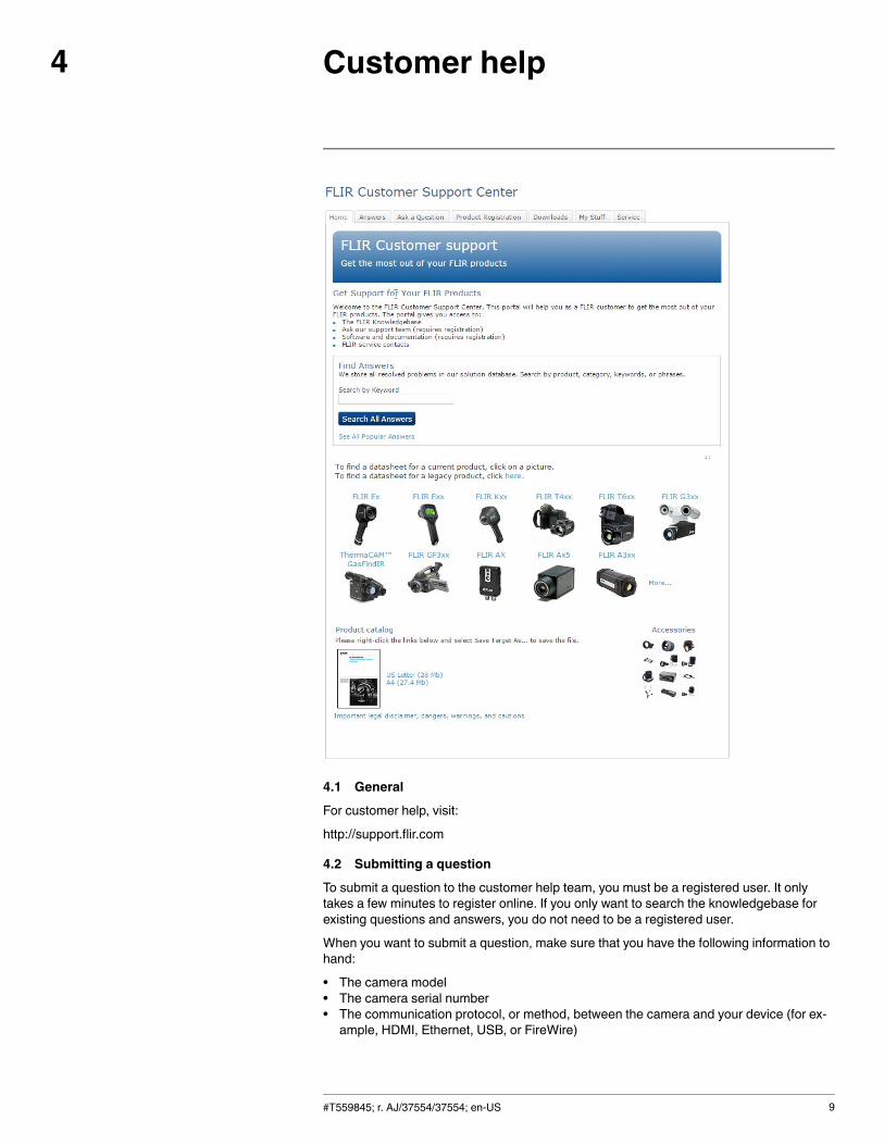
4.1 General
For customer help, visit:
http://support.flir.com
4.2 Submitting a question
To submit a question to the customer help team, you must be a registered user. It onlytakes a few minutes to register online. If you only want to search the knowledgebase forexisting questions and answers, you do not need to be a registered user.
When you want to submit a question, make sure that you have the following information tohand:
• The camera model• The camera serial number• The communication protocol, or method, between the camera and your device (for ex-ample, HDMI, Ethernet, USB, or FireWire)
#T559845; r. AJ/37554/37554; en-US 9
Customer help4
• Device type (PC/Mac/iPhone/iPad/Android device, etc.)• Version of any programs from FLIR Systems• Full name, publication number, and revision number of the manual
4.3 Downloads
On the customer help site you can also download the following, when applicable for theproduct:
• Firmware updates for your infrared camera.• Program updates for your PC/Mac software.• Freeware and evaluation versions of PC/Mac software.• User documentation for current, obsolete, and historical products.• Mechanical drawings (in *.dxf and *.pdf format).• Cad data models (in *.stp format).• Application stories.• Technical datasheets.• Product catalogs.
#T559845; r. AJ/37554/37554; en-US 10
Quick Start Guide5
5.1 Procedure
Follow this procedure:
1. Put a battery into the battery compartment.2. Charge the battery for 4 hours before starting the camera for the first time, or until the
green battery condition LED glows continuously.3. Insert a memory card into the card slot.
4. Push to turn on the camera.
5. Aim the camera toward the object of interest.6. Adjust the focus by rotating the focus ring.
Note It is very important to adjust the focus correctly. Incorrect focus adjustment af-fects how the image modes Thermal MSX, Thermal, and Picture-in-picture work. It alsoaffects the temperature measurement.
7. Push the Save button (the trigger) to save an image.8. Install FLIR Tools on your computer.9. Start FLIR Tools.10. Connect the camera to the computer using the USB cable.11. Import the images into FLIR Tools and create a PDF report.
#T559845; r. AJ/37554/37554; en-US 11

List of accessories and services6
Product name Part number
Battery charger, incl. power supply with multi plugs(Exx, Kxx)
T198125
Bluetooth Headset T197771ACC
Calibration including General maintenance Exx T199839
Cardboard box with printing 280 x 200 x 120 mm T127477
Cigarette lighter adapter kit, 12 VDC, 1.2 m/3.9 ft. T198509
FLIR Reporter Professional (license only) T198586
FLIR ResearchIR Max + HSDR 4 (hardware sec.dev.)
T198697
FLIR ResearchIR Max + HSDR 4 (printed licensekey)
T199014
FLIR ResearchIR Max + HSDR 4 Upgrade (printedlicense key)
T199044
FLIR ResearchIR Max 4 (hardware sec. dev.) T198696
FLIR ResearchIR Max 4 (printed license key) T199013
FLIR ResearchIR Max 4 Upgrade (printed licensekey)
T199043
FLIR ResearchIR Standard 4 (hardware sec. dev.) T198731
FLIR ResearchIR Standard 4 (printed license key) T199012
FLIR ResearchIR Standard 4 Upgrade (printed li-cense key)
T199042
FLIR Tools T198584
FLIR Tools+ (download card incl. license key) T198583
High-temperature lens T199235
IR lens, 76 mm (6°) with case and mounting sup-port for Exx
T198113
IR lens, f = 10 mm, 45° incl. case 1196960
IR lens, f = 30 mm, 15° incl. case 1196961
IRWindow 2 in 19250-100
IR Window 3 in. 19251-100
IR Window 4 in. 19252-100
Li-Ion Battery pack 3.7V 17Wh T198487
Memory card SDHC 4 GB T911230ACC
One year extended warranty for Exx series T199837
Pouch for FLIR Exx series T198484
Power supply, incl. multi plugs T910814
SS IR Window 2 in. 19250-200
SS IR Window 3 in. 19251-200
SS IR Window 4 in. 19252-200
Sun shield T198485
Tool belt T911093
Transport case Exx T198341ACC
#T559845; r. AJ/37554/37554; en-US 12
List of accessories and services6
Product name Part number
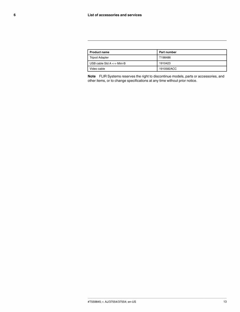
Tripod Adapter T198486
USB cable Std A <-> Mini-B 1910423
Video cable 1910582ACC
Note FLIR Systems reserves the right to discontinue models, parts or accessories, andother items, or to change specifications at any time without prior notice.
#T559845; r. AJ/37554/37554; en-US 13
Camera parts7
7.1 View from the right
7.1.1 Figure
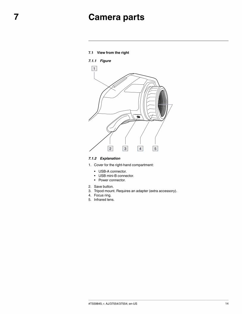
7.1.2 Explanation
1. Cover for the right-hand compartment:
• USB-A connector.• USB mini-B connector.• Power connector.
2. Save button.3. Tripod mount. Requires an adapter (extra accessory).4. Focus ring.5. Infrared lens.
#T559845; r. AJ/37554/37554; en-US 14
Camera parts7
7.2 View from the left
7.2.1 Figure
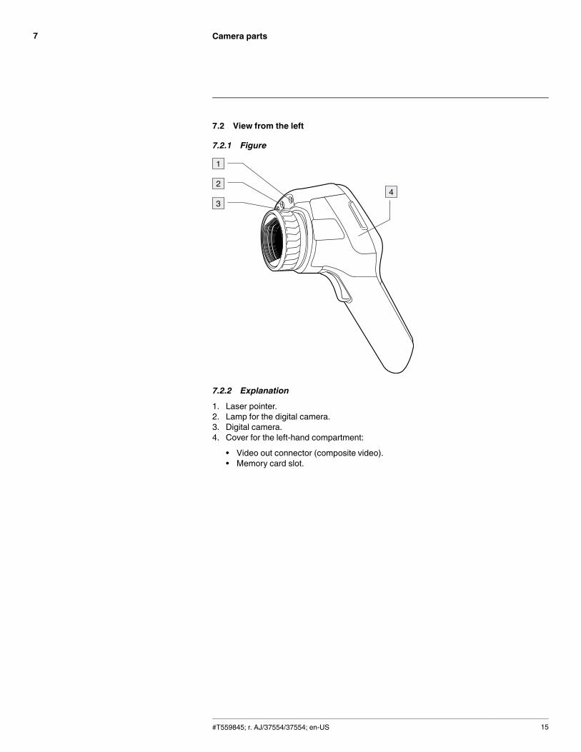
7.2.2 Explanation
1. Laser pointer.2. Lamp for the digital camera.3. Digital camera.4. Cover for the left-hand compartment:
• Video out connector (composite video).• Memory card slot.
#T559845; r. AJ/37554/37554; en-US 15
Camera parts7
7.3 LCD and keypad
7.3.1 Figure
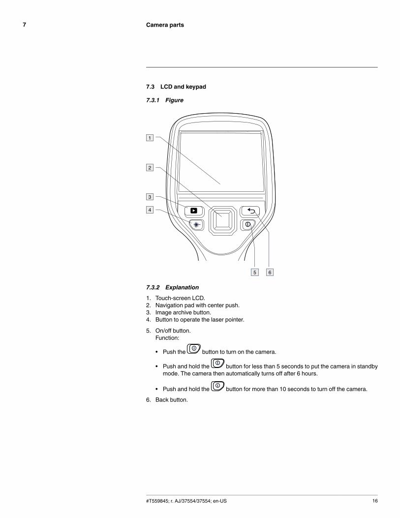
7.3.2 Explanation
1. Touch-screen LCD.2. Navigation pad with center push.3. Image archive button.4. Button to operate the laser pointer.
5. On/off button.Function:
• Push the button to turn on the camera.
• Push and hold the button for less than 5 seconds to put the camera in standbymode. The camera then automatically turns off after 6 hours.
• Push and hold the button for more than 10 seconds to turn off the camera.
6. Back button.
#T559845; r. AJ/37554/37554; en-US 16
Camera parts7
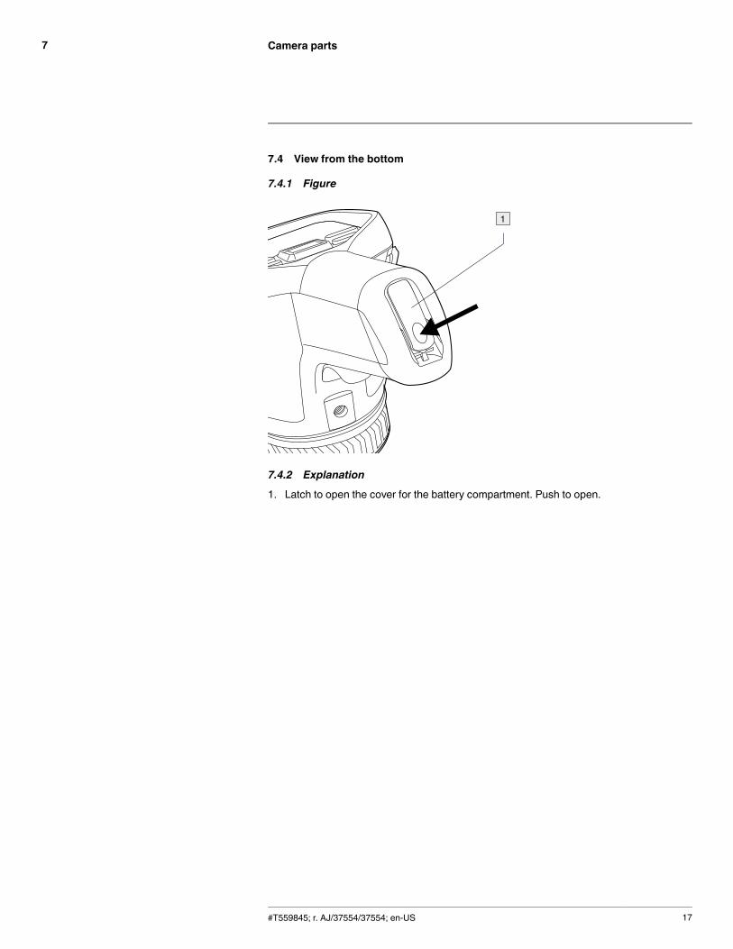
7.4 View from the bottom
7.4.1 Figure
7.4.2 Explanation
1. Latch to open the cover for the battery compartment. Push to open.
#T559845; r. AJ/37554/37554; en-US 17
Camera parts7
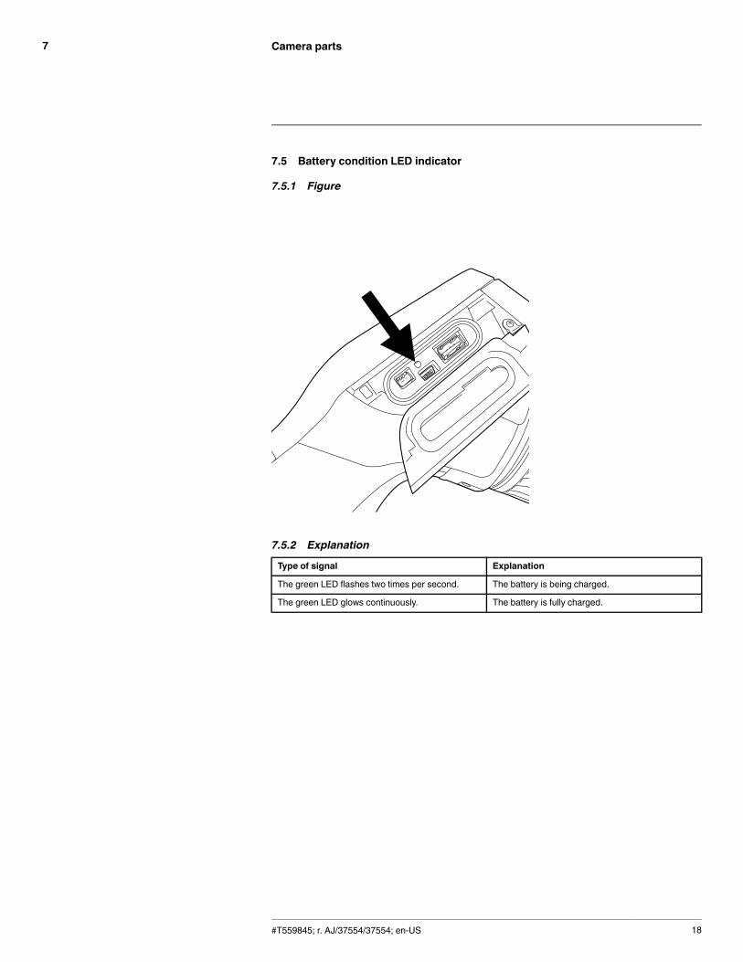
7.5 Battery condition LED indicator
7.5.1 Figure
7.5.2 Explanation
Type of signal Explanation
The green LED flashes two times per second. The battery is being charged.
The green LED glows continuously. The battery is fully charged.
#T559845; r. AJ/37554/37554; en-US 18
Camera parts7
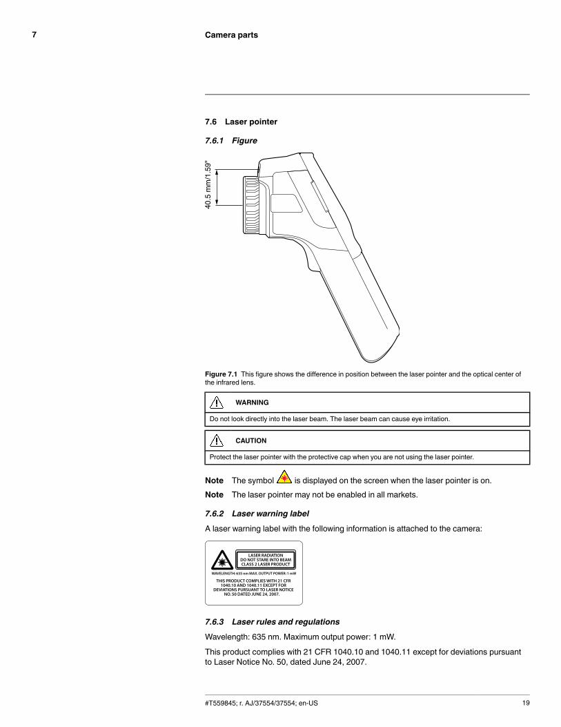
7.6 Laser pointer
7.6.1 Figure
Figure 7.1 This figure shows the difference in position between the laser pointer and the optical center ofthe infrared lens.
WARNING
Do not look directly into the laser beam. The laser beam can cause eye irritation.
CAUTION
Protect the laser pointer with the protective cap when you are not using the laser pointer.
Note The symbol is displayed on the screen when the laser pointer is on.Note The laser pointer may not be enabled in all markets.
7.6.2 Laser warning label
A laser warning label with the following information is attached to the camera:
7.6.3 Laser rules and regulations
Wavelength: 635 nm. Maximum output power: 1 mW.
This product complies with 21 CFR 1040.10 and 1040.11 except for deviations pursuantto Laser Notice No. 50, dated June 24, 2007.
#T559845; r. AJ/37554/37554; en-US 19
Screen elements8
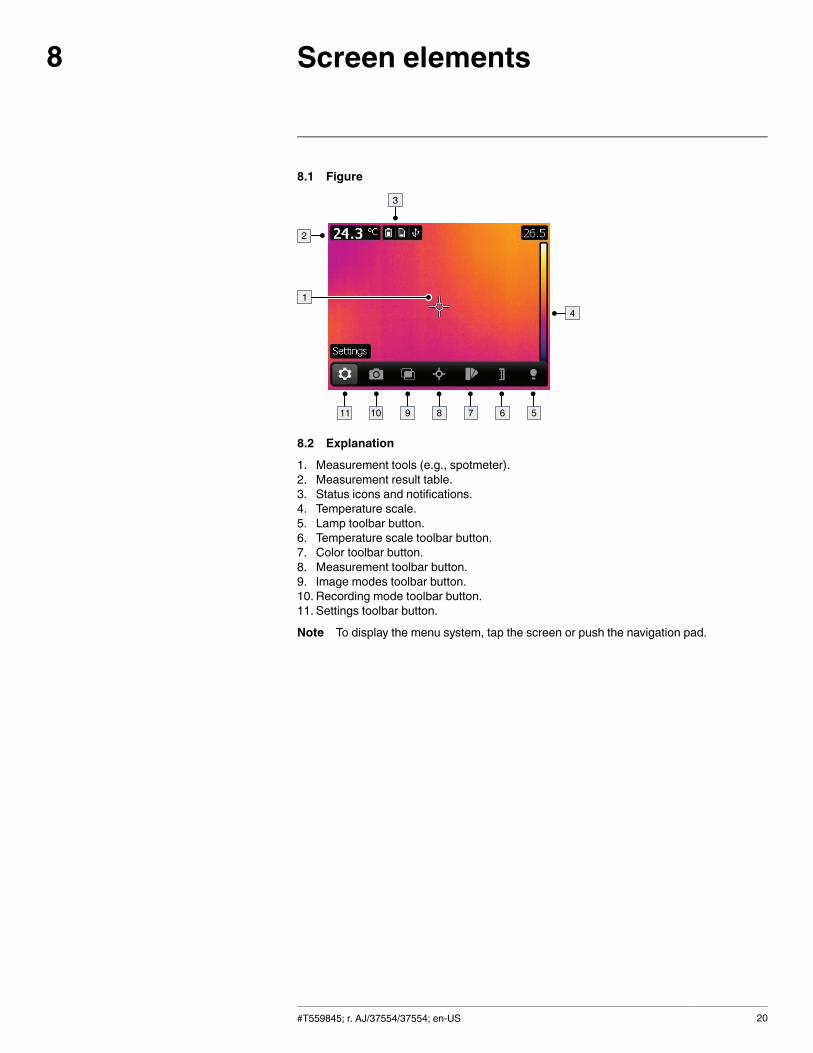
8.1 Figure
8.2 Explanation
1. Measurement tools (e.g., spotmeter).2. Measurement result table.3. Status icons and notifications.4. Temperature scale.5. Lamp toolbar button.6. Temperature scale toolbar button.7. Color toolbar button.8. Measurement toolbar button.9. Image modes toolbar button.10. Recording mode toolbar button.11. Settings toolbar button.
Note To display the menu system, tap the screen or push the navigation pad.
#T559845; r. AJ/37554/37554; en-US 20
Navigating the menu system9
9.1 Figure
9.2 Explanation
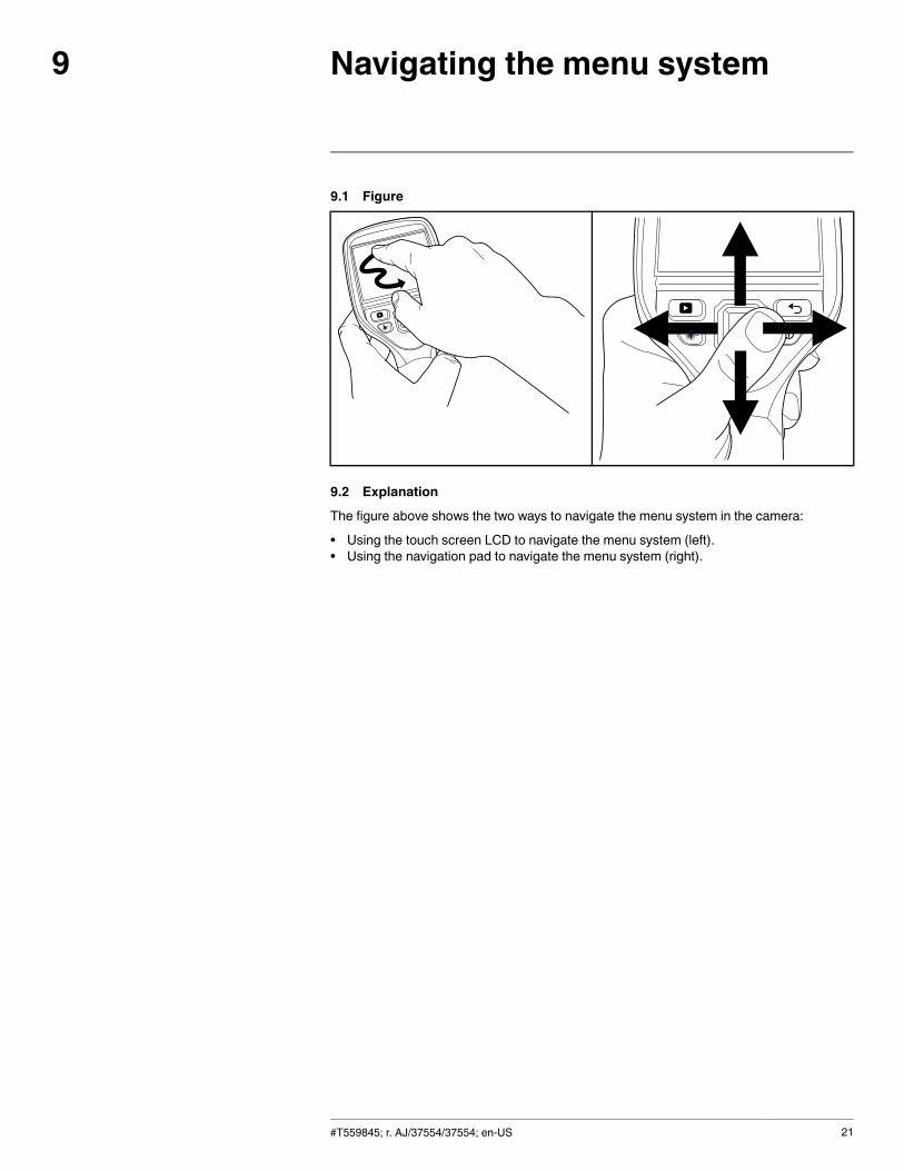
The figure above shows the two ways to navigate the menu system in the camera:
• Using the touch screen LCD to navigate the menu system (left).• Using the navigation pad to navigate the menu system (right).
#T559845; r. AJ/37554/37554; en-US 21
Connecting external devices andstorage media
10
10.1 Figure
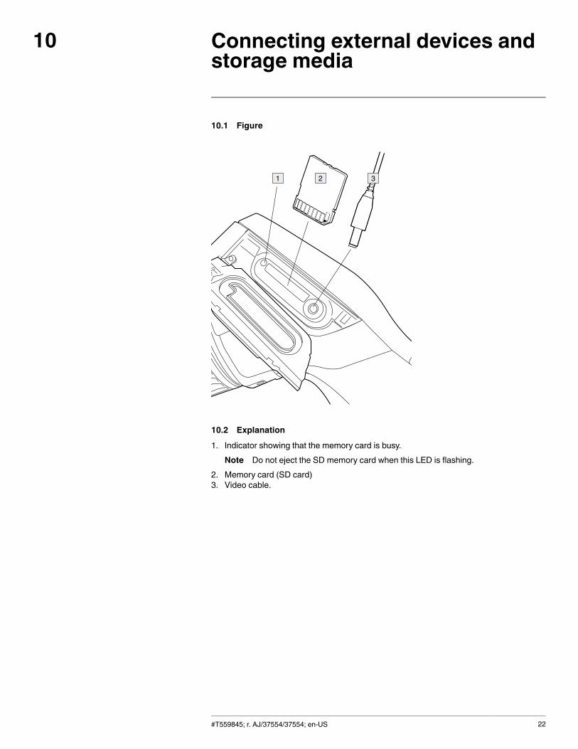
10.2 Explanation
1. Indicator showing that the memory card is busy.Note Do not eject the SD memory card when this LED is flashing.
2. Memory card (SD card)3. Video cable.
#T559845; r. AJ/37554/37554; en-US 22
Connecting external devices and storage media10
10.3 Figure
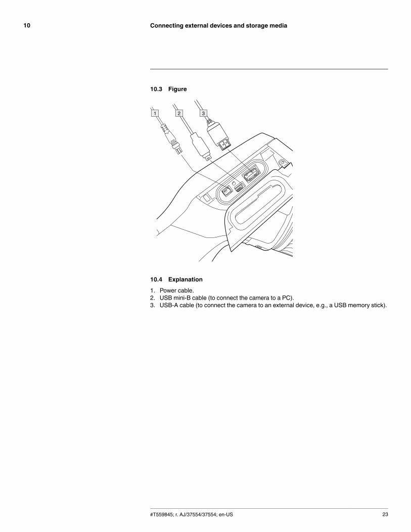
10.4 Explanation
1. Power cable.2. USB mini-B cable (to connect the camera to a PC).3. USB-A cable (to connect the camera to an external device, e.g., a USB memory stick).
#T559845; r. AJ/37554/37554; en-US 23
Pairing Bluetooth devices11
11.1 General
You can use Bluetooth-enabled headsets and FLIR meters together with the camera. Be-fore you can use the device with the camera, you need to pair the camera and the device.
11.2 Procedure
Follow this procedure:
1. Enable Bluetooth on the device. See the user documentation for that device for infor-mation on how to do this.
2. On the camera, push the navigation pad to display the menu system.3. Use the navigation pad to go to Settings.4. Push the navigation pad.5. Select Device settings and push the navigation pad.6. Select Bluetooth including METERLiNK and push the navigation pad.7. Enable Bluetooth by pushing the navigation pad.8. Select Scan for Bluetooth devices and push the navigation pad right.9. When the device is displayed in the list of devices, select it and push the navigation
pad to pair the camera and the device.
Note
• Only METERLiNK devices and Bluetooth-enabled headsets will appear in the list ofavailable devices.
• You can add several devices.• You can remove a device by selecting the device and then selecting Unpair device.• After adding a METERLiNK device, such as the FLIR MR77 or FLIR CM78, the resultfrom the meter will be visible in the measurement result table.
• After adding a Bluetooth-enabled headset, it is ready to be used for adding voiceannotations.
#T559845; r. AJ/37554/37554; en-US 24
Configuring Wi-Fi12
12.1 General
You can connect the camera in two different ways:
• Most common use: Setting up a peer-to-peer connection (also called an ad hoc or P2Pconnection). This method is primarily used with other devices, e.g., an iPhone or iPad.
• Less common use: Connecting the camera to a wireless local area network (WLAN).
12.2 Setting up a peer-to-peer connection (most common use)
Follow this procedure:
1. On the camera, push the navigation pad to display the menu system.2. Use the navigation pad to go to Settings.3. Push the navigation pad.4. Select Device settings and push the navigation pad.5. SelectWi-Fi and push the navigation pad.6. Select Share and push the navigation pad.7. (Optional step.) To display and change the parameters, select Settings and push the
navigation pad.
• If the transfer rate is low, this can be due to a crowded frequency band. Try chang-ing the channel to increase the transfer rate. To change the channel (the channelthat the camera is broadcasting on), select Channel and push the navigation pad.
• To activate WEP (encryption algorithm), selectWEP and push the navigation pad.This will check theWEP check box.
• To change the WEP password, select Password and push the navigation pad.
Note These parameters are set for your camera’s network. They will be used by theexternal device to connect that device to the network.
12.3 Connecting the camera to a wireless local area network (less common use)
Follow this procedure:
1. On the camera, push the navigation pad to display the menu system.2. Use the navigation pad to go to Settings .3. Push the navigation pad.4. Select Device settings and push the navigation pad.5. SelectWi-Fi and push the navigation pad.6. Select Connect to network and push the navigation pad.7. Select Networks and push the navigation pad right.8. Select a network by pushing the navigation pad. You typically need to enter a pass-
word to access the network.
Note Some networks do not broadcast their existence. To connect to such a network,select Settings from the Networks list and push the navigation pad. Then select Add net-work... and set all parameters manually for that network.
#T559845; r. AJ/37554/37554; en-US 25
Handling the camera13
13.1 Charging the battery
Note You must charge the battery for 4 hours before you start using the camera for thefirst time.
13.1.1 Using the power supply to charge the battery
13.1.1.1 Procedure
Follow this procedure:
1. Connect the power supply cable plug to the power connector on the camera.2. Connect the power supply mains-electricity plug to a mains socket.3. Disconnect the power supply cable plug when the battery condition LED indicator is a
continuous green.
13.1.2 Using the stand-alone battery charger to charge the battery
13.1.2.1 Explanation
Type of signal Explanation
The blue LED flashes. The battery is being charged.
The blue LED glows continuously. The battery is fully charged.
13.1.2.2 Procedure
Follow this procedure:
1. Put the battery in the battery charger.2. Connect the power supply cable plug to the connector on the battery charger.3. Connect the power supply mains-electricity plug to a mains socket.4. Disconnect the power supply cable plug when the blue LED on the battery charger is
continuous.
13.2 Turning on and turning off the camera
• Push the button to turn on the camera.
• Push and hold the button for less than 5 seconds to put the camera in standbymode. The camera then automatically turns off after 6 hours.
• Push and hold the button for more than 10 seconds to turn off the camera.
#T559845; r. AJ/37554/37554; en-US 26
Handling the camera13
13.3 Adjusting the infrared camera focus
13.3.1 Figure
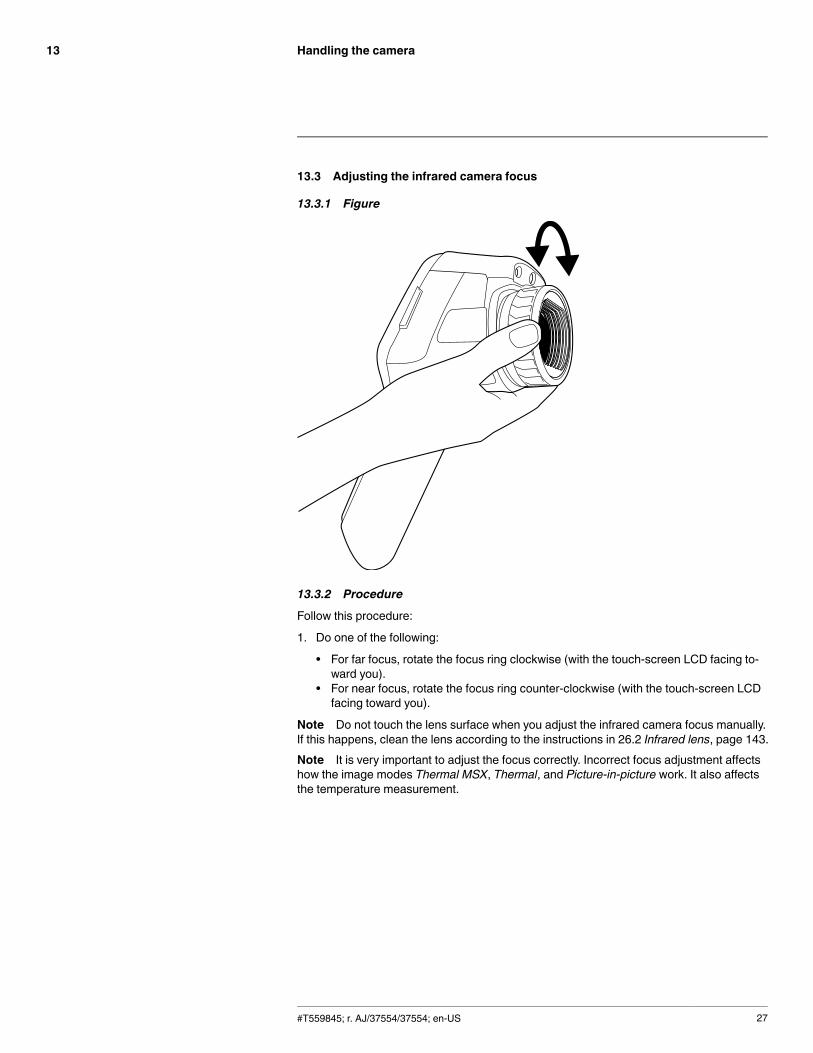
13.3.2 Procedure
Follow this procedure:
1. Do one of the following:
• For far focus, rotate the focus ring clockwise (with the touch-screen LCD facing to-ward you).
• For near focus, rotate the focus ring counter-clockwise (with the touch-screen LCDfacing toward you).
Note Do not touch the lens surface when you adjust the infrared camera focus manually.If this happens, clean the lens according to the instructions in 26.2 Infrared lens, page 143.Note It is very important to adjust the focus correctly. Incorrect focus adjustment affectshow the image modes Thermal MSX, Thermal, and Picture-in-picture work. It also affectsthe temperature measurement.
#T559845; r. AJ/37554/37554; en-US 27
Handling the camera13
13.4 Operating the laser pointer
13.4.1 Figure
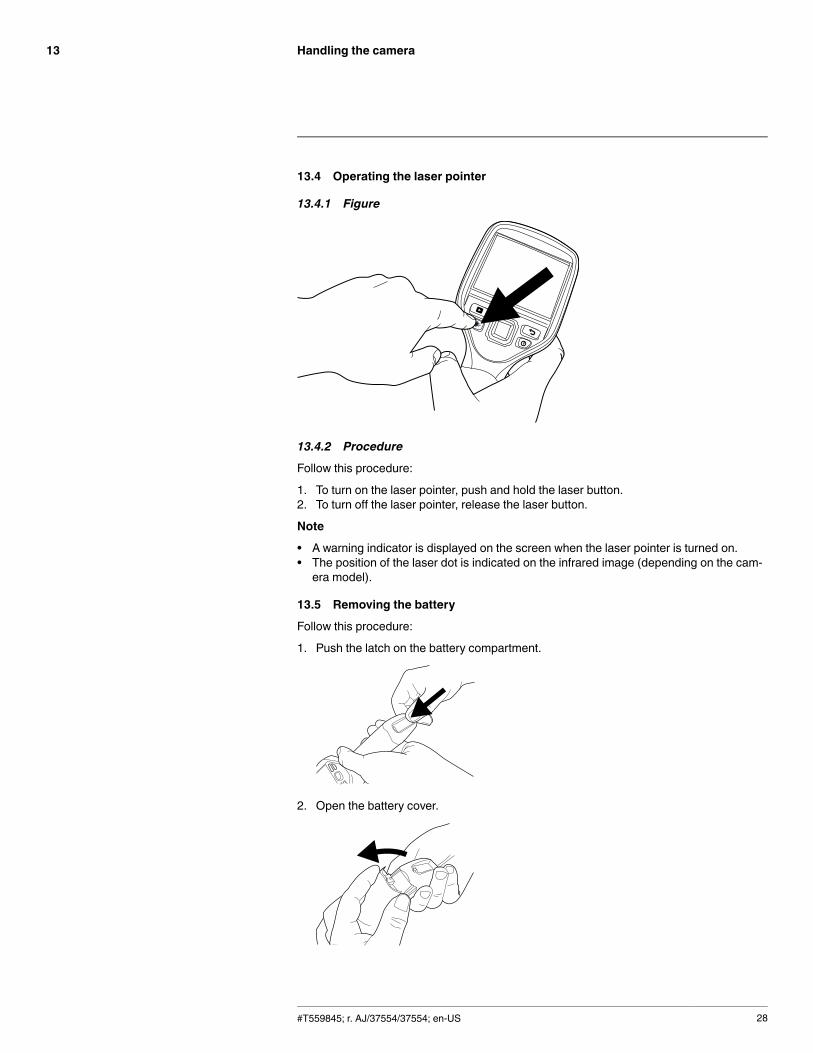
13.4.2 Procedure
Follow this procedure:
1. To turn on the laser pointer, push and hold the laser button.2. To turn off the laser pointer, release the laser button.
Note
• A warning indicator is displayed on the screen when the laser pointer is turned on.• The position of the laser dot is indicated on the infrared image (depending on the cam-era model).
13.5 Removing the battery
Follow this procedure:
1. Push the latch on the battery compartment.
2. Open the battery cover.
#T559845; r. AJ/37554/37554; en-US 28
Handling the camera13
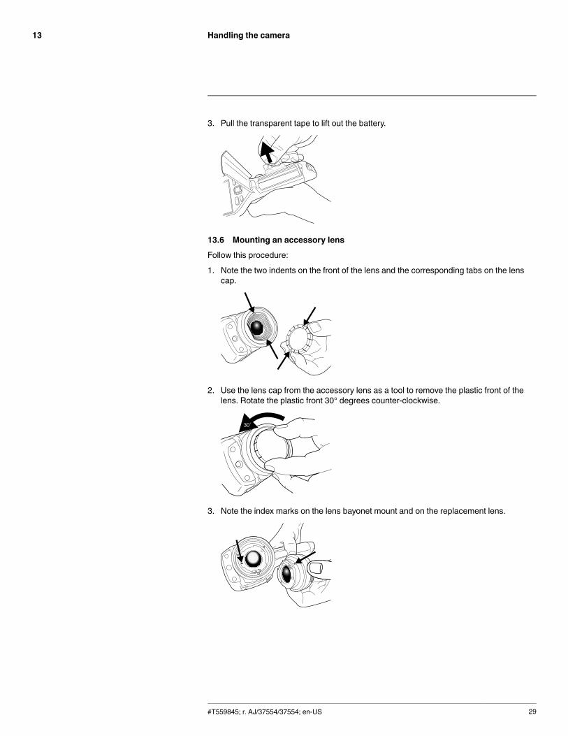
3. Pull the transparent tape to lift out the battery.
13.6 Mounting an accessory lens
Follow this procedure:
1. Note the two indents on the front of the lens and the corresponding tabs on the lenscap.
2. Use the lens cap from the accessory lens as a tool to remove the plastic front of thelens. Rotate the plastic front 30° degrees counter-clockwise.
3. Note the index marks on the lens bayonet mount and on the replacement lens.
#T559845; r. AJ/37554/37554; en-US 29
Handling the camera13
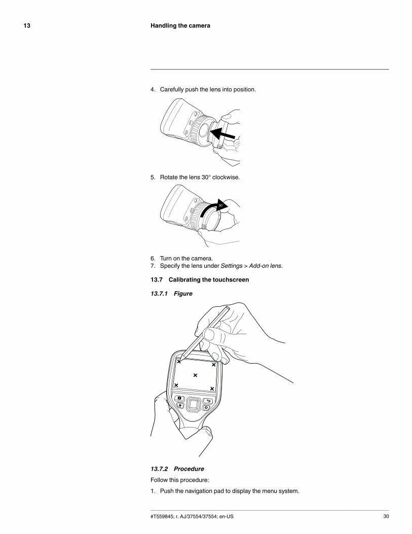
4. Carefully push the lens into position.
5. Rotate the lens 30° clockwise.
6. Turn on the camera.7. Specify the lens under Settings > Add-on lens.
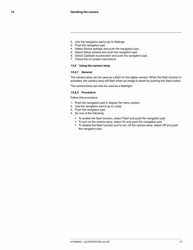
13.7 Calibrating the touchscreen
13.7.1 Figure
13.7.2 Procedure
Follow this procedure:
1. Push the navigation pad to display the menu system.
#T559845; r. AJ/37554/37554; en-US 30
Handling the camera13
2. Use the navigation pad to go to Settings.3. Push the navigation pad.4. Select Device settings and push the navigation pad.5. Select Setup camera and push the navigation pad.6. Select Calibrate touchscreen and push the navigation pad.7. Follow the on-screen instructions.
13.8 Using the camera lamp
13.8.1 General
The camera lamp can be used as a flash for the digital camera. When the flash function isactivated, the camera lamp will flash when an image is saved by pushing the Save button.
The camera lamp can also be used as a flashlight.
13.8.2 Procedure
Follow this procedure:
1. Push the navigation pad to display the menu system.2. Use the navigation pad to go to Lamp.3. Push the navigation pad.4. Do one of the following:
• To enable the flash function, select Flash and push the navigation pad.• To turn on the camera lamp, select On and push the navigation pad.• To disable the flash function and to turn off the camera lamp, select Off and pushthe navigation pad.
#T559845; r. AJ/37554/37554; en-US 31
Working with images14
14.1 Saving an image
14.1.1 General
You can save images to a memory card.
The camera saves an image file including all thermal and visual information. This meansthat you can open an image file at a later time and, for example, select another imagemode, apply color alarms, and add measurement tools.
14.1.2 Image capacity
This table gives information on the approximate number of infrared (IR) and digital camera(DC) images that can be saved on memory cards:
Card size IR only IR + DCIR + DC + 30 secondsvoice annotation
1 GB 5500 850 600
2 GB 11 000 1700 1200
14.1.3 Naming convention
The naming convention for images is FLIRxxxx.jpg, where xxxx is a unique counter.
14.1.4 Procedure
Follow this procedure:
1. To save an image, push the Save button.
Note
• Depending on the settings in the Settings > Save options dialog box, the following mayhappen:
◦ A preview image is displayed before the image is saved.◦ An annotation tool or the annotation menu is displayed when the image has beensaved.
14.2 Previewing an image
14.2.1 General
You can preview an image before you save it. This enables you to see if the image containsthe information you want before you save it. You can also adjust and edit the image.
Note The camera must be configured to display a preview image before saving. SelectSettings> Save options > Preview image before saving = On.
14.2.2 Procedure
Follow this procedure:
1. To preview an image, push the Save button. This displays the preview.
2. Manual image adjust mode is now active, and the status icon is displayed. For im-age adjustment instructions, see 14.5 Adjusting an infrared image, page 34.
3. To edit the image, push the navigation pad. This displays a toolbar. For editing instruc-tions, see 14.4 Editing a saved image, page 33.
#T559845; r. AJ/37554/37554; en-US 32
Working with images14
4. Do one of the following:
• To save the image, push the Save button.
• To exit preview mode without saving, push the Back button . A dialog box ap-pears, asking you to cancel or save any changes.
14.3 Opening a saved image
14.3.1 General
When you save an image, the image is stored on a memory card. To display the imageagain, open it from the memory card.
14.3.2 Procedure
Follow this procedure:
1. Push to open the image archive.
2. Push the navigation pad up/down or left/right to select the image you want to view.3. Push the navigation pad to open the image.
4. Do one or more of the following:
• To switch between an infrared image and a visual image, push the navigation padup/down.
• To view the previous/next image, push the navigation pad left/right.• To edit the image, add annotations, display information, or delete the image, pushthe navigation pad. This displays a toolbar.
• To return to the image archive overview, push the Back button .
5. Push the Back button to leave the image archive.
14.4 Editing a saved image
14.4.1 General
You can edit a saved image. You can also edit an image in preview mode.
14.4.2 Procedure
Follow this procedure:
1. Open the image in the image archive.2. Push the navigation pad and select Edit from the toolbar.
3. Manual image adjust mode is now active, and the status icon is displayed. For im-age adjustment instructions, see 14.5 Adjusting an infrared image, page 34.
4. Push the navigation pad. This displays a toolbar.
• Select Cancel to exit edit mode.• SelectMeasurement parameters to change the global parameters.• Select Image mode to change the image mode.• SelectMeasurement to add a measurement tool.• Select Color to change the color palette or set a color alarm.• Select Temperature scale to adjust the image.• Select Save to save and exit edit mode.
#T559845; r. AJ/37554/37554; en-US 33
Working with images14
14.5 Adjusting an infrared image
14.5.1 General
An infrared image can be adjusted automatically or manually. When manual image adjust
mode is active, the status icon is displayed.
• In live mode, select Temperature scale from the menu system to switch between auto-matic and manual image adjust modes.
• In live mode, you can also select manual image adjust mode by touching the minimumor maximum temperature scale level on the screen.
• In preview/edit mode, manual image adjust mode is active.
There are two different manual image adjust modes. Select the type of mode under Set-tings > Device settings > Set up camera > Level span mode.
• Level / span: This mode allows you to manually adjust the level and span of the temper-ature scale.
• Level / max / min: In this mode, you can manually adjust the temperature scale mini-mum and maximum limits, simultaneously or individually.
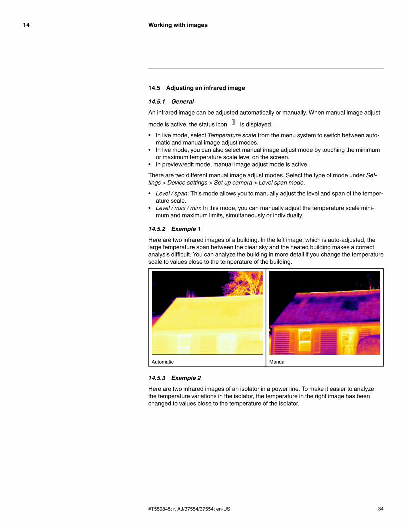
14.5.2 Example 1
Here are two infrared images of a building. In the left image, which is auto-adjusted, thelarge temperature span between the clear sky and the heated building makes a correctanalysis difficult. You can analyze the building in more detail if you change the temperaturescale to values close to the temperature of the building.
Automatic Manual
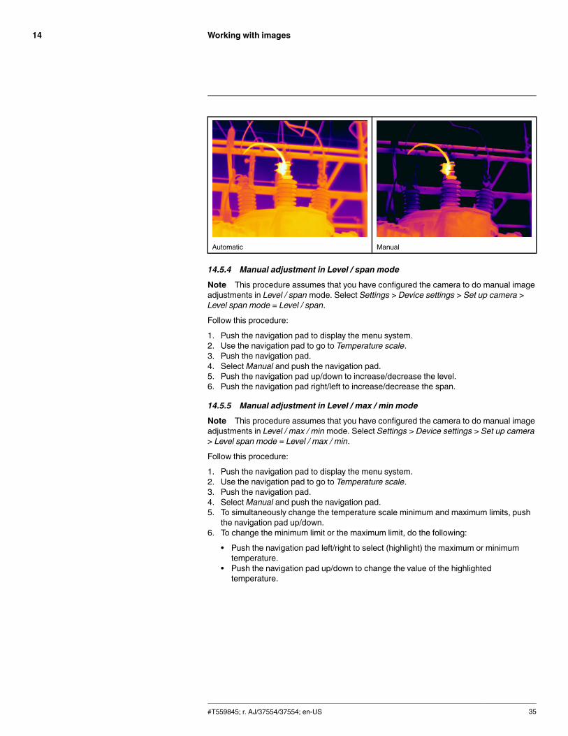
14.5.3 Example 2
Here are two infrared images of an isolator in a power line. To make it easier to analyzethe temperature variations in the isolator, the temperature in the right image has beenchanged to values close to the temperature of the isolator.
#T559845; r. AJ/37554/37554; en-US 34
Working with images14
Automatic Manual
14.5.4 Manual adjustment in Level / span mode
Note This procedure assumes that you have configured the camera to do manual imageadjustments in Level / span mode. Select Settings > Device settings > Set up camera >Level span mode = Level / span.
Follow this procedure:
1. Push the navigation pad to display the menu system.2. Use the navigation pad to go to Temperature scale.3. Push the navigation pad.4. SelectManual and push the navigation pad.5. Push the navigation pad up/down to increase/decrease the level.6. Push the navigation pad right/left to increase/decrease the span.
14.5.5 Manual adjustment in Level / max / min mode
Note This procedure assumes that you have configured the camera to do manual imageadjustments in Level / max / minmode. Select Settings > Device settings > Set up camera> Level span mode = Level / max / min.
Follow this procedure:
1. Push the navigation pad to display the menu system.2. Use the navigation pad to go to Temperature scale.3. Push the navigation pad.4. SelectManual and push the navigation pad.5. To simultaneously change the temperature scale minimum and maximum limits, push
the navigation pad up/down.6. To change the minimum limit or the maximum limit, do the following:
• Push the navigation pad left/right to select (highlight) the maximum or minimumtemperature.
• Push the navigation pad up/down to change the value of the highlightedtemperature.
#T559845; r. AJ/37554/37554; en-US 35
Working with images14
14.6 Performing a non-uniformity correction (NUC)
14.6.1 What is a non-uniformity correction?
A non-uniformity correction is an image correction carried out by the camera software tocompensate for different sensitivities of detector elements and other optical and geometri-cal disturbances1.
14.6.2 When to perform a non-uniformity correction?
The non-uniformity correction process should be carried out whenever the output imagebecomes spatially noisy. The output can become spatially noisy when the ambient temper-ature changes (such as from day to night operation, and vice versa).
14.6.3 Procedure
To perform a non-uniformity correction, push and hold the Image archive button formore than 2 seconds.
14.7 Changing the temperature range
14.7.1 General
You must change the temperature range according to the expected temperature of the ob-ject you are inspecting.
14.7.2 Procedure
Follow this procedure:
1. Push the navigation pad to display the menu system.2. Use the navigation pad to go to Settings.3. Push the navigation pad.4. Select Device settings and push the navigation pad.5. Select Set up camera and push the navigation pad.6. Select Camera temperature range and push the navigation pad.7. Select the appropriate temperature range and push the navigation pad.
14.8 Changing the color palette
14.8.1 General
You can change the color palette that the camera uses to display different temperatures. Adifferent palette can make it easier to analyze an image.
14.8.2 Procedure
Follow this procedure:
1. Push the navigation pad to display the menu system.2. Use the navigation pad to go to Color.3. Push the navigation pad.4. Use the navigation pad to select a different color palette.5. Push the navigation pad to confirm the choice.
Note Some color options hold specific meanings, such as acting as isotherms or alarms.For more information, see section 17Working with alarms, page 43.
#T559845; r. AJ/37554/37554; en-US 36
1. Definition from the impending international adoption of DIN 54190-3 (Non-destructive testing – Thermographictesting – Part 3: Terms and definitions).
Working with images14
14.9 Zooming in on an image
14.9.1 General
You can zoom in on an image using the camera’s digital zoom function. You can do this onboth live images and saved images.
14.9.2 Procedure
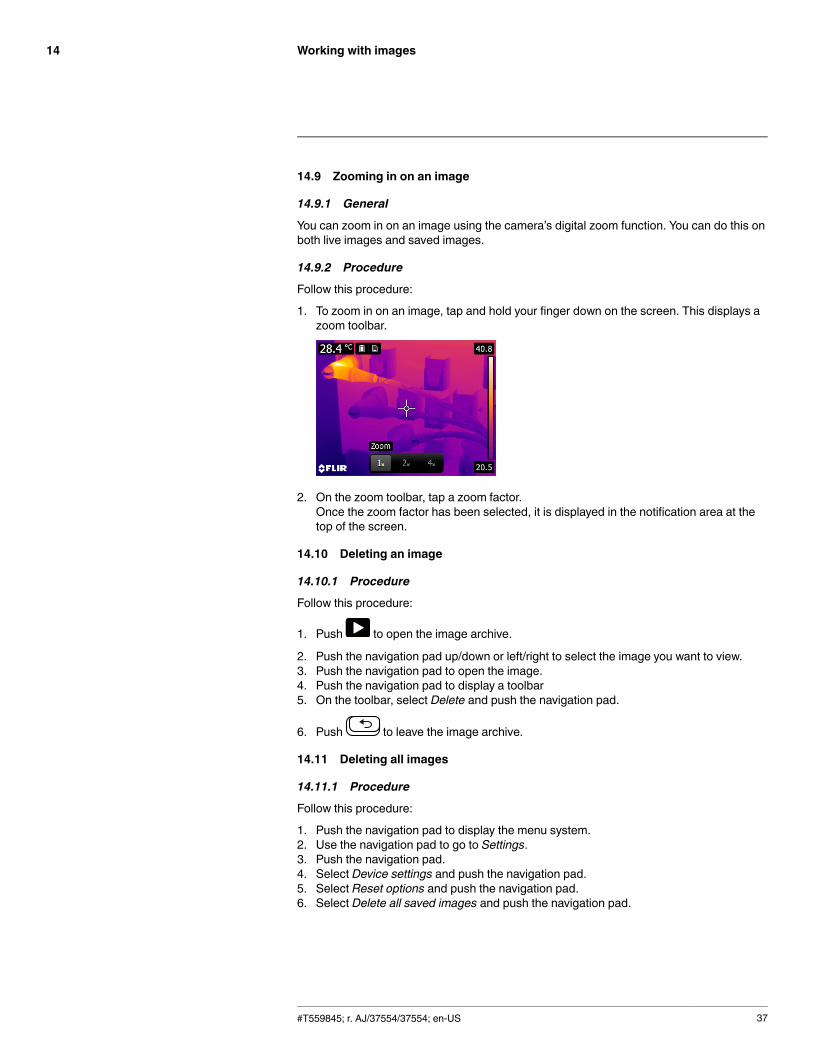
Follow this procedure:
1. To zoom in on an image, tap and hold your finger down on the screen. This displays azoom toolbar.
2. On the zoom toolbar, tap a zoom factor.Once the zoom factor has been selected, it is displayed in the notification area at thetop of the screen.
14.10 Deleting an image
14.10.1 Procedure
Follow this procedure:
1. Push to open the image archive.
2. Push the navigation pad up/down or left/right to select the image you want to view.3. Push the navigation pad to open the image.4. Push the navigation pad to display a toolbar5. On the toolbar, select Delete and push the navigation pad.
6. Push to leave the image archive.
14.11 Deleting all images
14.11.1 Procedure
Follow this procedure:
1. Push the navigation pad to display the menu system.2. Use the navigation pad to go to Settings.3. Push the navigation pad.4. Select Device settings and push the navigation pad.5. Select Reset options and push the navigation pad.6. Select Delete all saved images and push the navigation pad.
#T559845; r. AJ/37554/37554; en-US 37
Working with image modes15
15.1 General
You can choose between different image modes when capturing an image.
15.2 Types of image modes
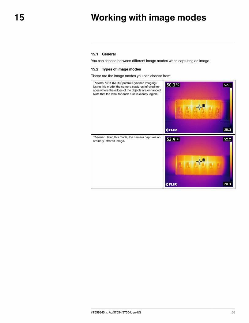
These are the image modes you can choose from:
Thermal MSX (Multi Spectral Dynamic Imaging):Using this mode, the camera captures infrared im-ages where the edges of the objects are enhanced.Note that the label for each fuse is clearly legible.
Thermal: Using this mode, the camera captures anordinary infrared image.
#T559845; r. AJ/37554/37554; en-US 38
Working with image modes15
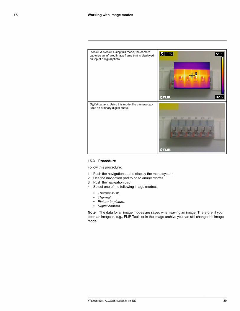
Picture-in-picture: Using this mode, the cameracaptures an infrared image frame that is displayedon top of a digital photo.
Digital camera: Using this mode, the camera cap-tures an ordinary digital photo.
15.3 Procedure
Follow this procedure:
1. Push the navigation pad to display the menu system.2. Use the navigation pad to go to Image modes.3. Push the navigation pad.4. Select one of the following image modes:
• Thermal MSX.• Thermal.• Picture-in-picture.• Digital camera.
Note The data for all image modes are saved when saving an image. Therefore, if youopen an image in, e.g., FLIR Tools or in the image archive you can still change the imagemode.
#T559845; r. AJ/37554/37554; en-US 39
Working with measurement tools16
16.1 Laying out measurement tools in live mode
16.1.1 General
To measure a temperature, you use one or more measurement tools, e.g., a spotmeter ora box. The camera is equipped with a number of preset measurement tools.
16.1.2 Procedure
Follow this procedure:
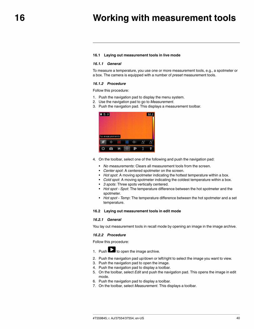
1. Push the navigation pad to display the menu system.2. Use the navigation pad to go toMeasurement.3. Push the navigation pad. This displays a measurement toolbar.
4. On the toolbar, select one of the following and push the navigation pad:
• No measurements: Clears all measurement tools from the screen.• Center spot: A centered spotmeter on the screen.• Hot spot: A moving spotmeter indicating the hottest temperature within a box.• Cold spot: A moving spotmeter indicating the coldest temperature within a box.• 3 spots: Three spots vertically centered.• Hot spot - Spot: The temperature difference between the hot spotmeter and thespotmeter.
• Hot spot - Temp: The temperature difference between the hot spotmeter and a settemperature.
16.2 Laying out measurement tools in edit mode
16.2.1 General
You lay out measurement tools in recall mode by opening an image in the image archive.
16.2.2 Procedure
Follow this procedure:
1. Push to open the image archive.
2. Push the navigation pad up/down or left/right to select the image you want to view.3. Push the navigation pad to open the image.4. Push the navigation pad to display a toolbar.5. On the toolbar, select Edit and push the navigation pad. This opens the image in edit
mode.6. Push the navigation pad to display a toolbar.7. On the toolbar, selectMeasurement. This displays a toolbar.
#T559845; r. AJ/37554/37554; en-US 40
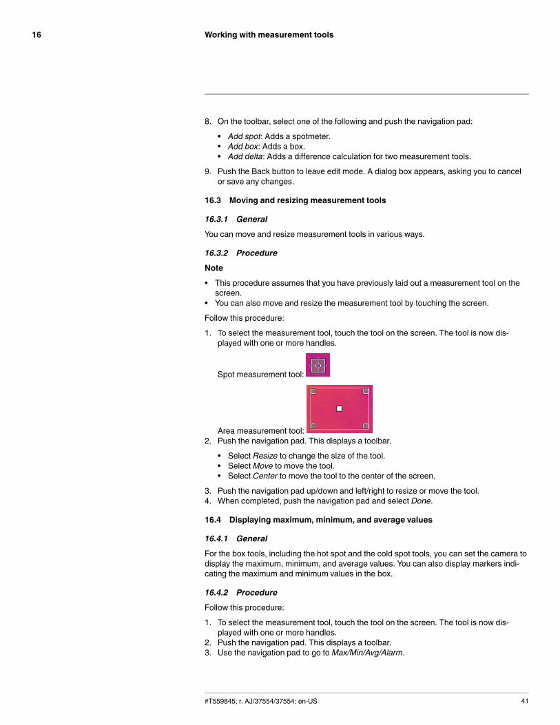
Working with measurement tools16
8. On the toolbar, select one of the following and push the navigation pad:
• Add spot: Adds a spotmeter.• Add box: Adds a box.• Add delta: Adds a difference calculation for two measurement tools.
9. Push the Back button to leave edit mode. A dialog box appears, asking you to cancelor save any changes.
16.3 Moving and resizing measurement tools
16.3.1 General
You can move and resize measurement tools in various ways.
16.3.2 Procedure
Note
• This procedure assumes that you have previously laid out a measurement tool on thescreen.
• You can also move and resize the measurement tool by touching the screen.
Follow this procedure:
1. To select the measurement tool, touch the tool on the screen. The tool is now dis-played with one or more handles.
Spot measurement tool:
Area measurement tool:2. Push the navigation pad. This displays a toolbar.
• Select Resize to change the size of the tool.• SelectMove to move the tool.• Select Center to move the tool to the center of the screen.
3. Push the navigation pad up/down and left/right to resize or move the tool.4. When completed, push the navigation pad and select Done.
16.4 Displaying maximum, minimum, and average values
16.4.1 General
For the box tools, including the hot spot and the cold spot tools, you can set the camera todisplay the maximum, minimum, and average values. You can also display markers indi-cating the maximum and minimum values in the box.
16.4.2 Procedure
Follow this procedure:
1. To select the measurement tool, touch the tool on the screen. The tool is now dis-played with one or more handles.
2. Push the navigation pad. This displays a toolbar.3. Use the navigation pad to go toMax/Min/Avg/Alarm.
#T559845; r. AJ/37554/37554; en-US 41
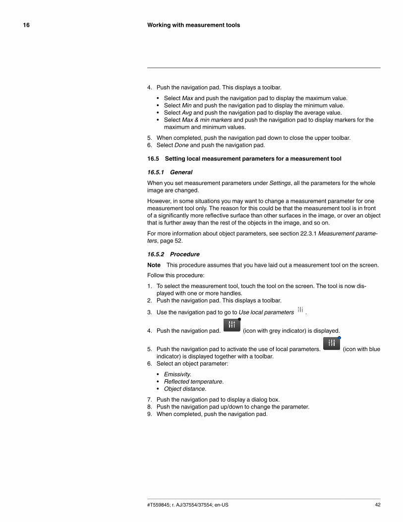
Working with measurement tools16
4. Push the navigation pad. This displays a toolbar.
• SelectMax and push the navigation pad to display the maximum value.• SelectMin and push the navigation pad to display the minimum value.• Select Avg and push the navigation pad to display the average value.• SelectMax & min markers and push the navigation pad to display markers for themaximum and minimum values.
5. When completed, push the navigation pad down to close the upper toolbar.6. Select Done and push the navigation pad.
16.5 Setting local measurement parameters for a measurement tool
16.5.1 General
When you set measurement parameters under Settings, all the parameters for the wholeimage are changed.
However, in some situations you may want to change a measurement parameter for onemeasurement tool only. The reason for this could be that the measurement tool is in frontof a significantly more reflective surface than other surfaces in the image, or over an objectthat is further away than the rest of the objects in the image, and so on.
For more information about object parameters, see section 22.3.1 Measurement parame-ters, page 52.
16.5.2 Procedure
Note This procedure assumes that you have laid out a measurement tool on the screen.Follow this procedure:
1. To select the measurement tool, touch the tool on the screen. The tool is now dis-played with one or more handles.
2. Push the navigation pad. This displays a toolbar.
3. Use the navigation pad to go to Use local parameters .
4. Push the navigation pad. (icon with grey indicator) is displayed.
5. Push the navigation pad to activate the use of local parameters. (icon with blueindicator) is displayed together with a toolbar.
6. Select an object parameter:
• Emissivity.• Reflected temperature.• Object distance.
7. Push the navigation pad to display a dialog box.8. Push the navigation pad up/down to change the parameter.9. When completed, push the navigation pad.
#T559845; r. AJ/37554/37554; en-US 42
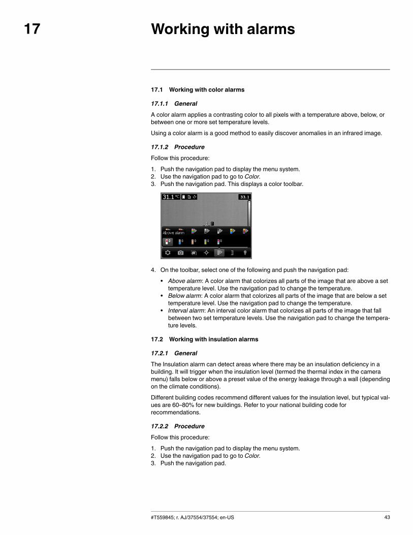
Working with alarms17
17.1 Working with color alarms
17.1.1 General
A color alarm applies a contrasting color to all pixels with a temperature above, below, orbetween one or more set temperature levels.
Using a color alarm is a good method to easily discover anomalies in an infrared image.
17.1.2 Procedure
Follow this procedure:
1. Push the navigation pad to display the menu system.2. Use the navigation pad to go to Color.3. Push the navigation pad. This displays a color toolbar.
4. On the toolbar, select one of the following and push the navigation pad:
• Above alarm: A color alarm that colorizes all parts of the image that are above a settemperature level. Use the navigation pad to change the temperature.
• Below alarm: A color alarm that colorizes all parts of the image that are below a settemperature level. Use the navigation pad to change the temperature.
• Interval alarm: An interval color alarm that colorizes all parts of the image that fallbetween two set temperature levels. Use the navigation pad to change the tempera-ture levels.
17.2 Working with insulation alarms
17.2.1 General
The Insulation alarm can detect areas where there may be an insulation deficiency in abuilding. It will trigger when the insulation level (termed the thermal index in the cameramenu) falls below or above a preset value of the energy leakage through a wall (dependingon the climate conditions).
Different building codes recommend different values for the insulation level, but typical val-ues are 60–80% for new buildings. Refer to your national building code forrecommendations.
17.2.2 Procedure
Follow this procedure:
1. Push the navigation pad to display the menu system.2. Use the navigation pad to go to Color.3. Push the navigation pad.
#T559845; r. AJ/37554/37554; en-US 43
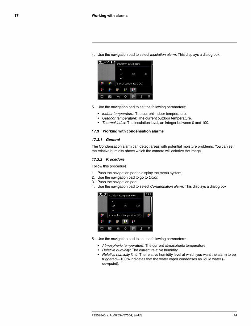
Working with alarms17
4. Use the navigation pad to select Insulation alarm. This displays a dialog box.
5. Use the navigation pad to set the following parameters:
• Indoor temperature: The current indoor temperature.• Outdoor temperature: The current outdoor temperature.• Thermal index: The insulation level, an integer between 0 and 100.
17.3 Working with condensation alarms
17.3.1 General
The Condensation alarm can detect areas with potential moisture problems. You can setthe relative humidity above which the camera will colorize the image.
17.3.2 Procedure
Follow this procedure:
1. Push the navigation pad to display the menu system.2. Use the navigation pad to go to Color.3. Push the navigation pad.4. Use the navigation pad to select Condensation alarm. This displays a dialog box.
5. Use the navigation pad to set the following parameters:
• Atmospheric temperature: The current atmospheric temperature.• Relative humidity: The current relative humidity.• Relative humidity limit: The relative humidity level at which you want the alarm to betriggered—100% indicates that the water vapor condenses as liquid water (=dewpoint).
#T559845; r. AJ/37554/37554; en-US 44
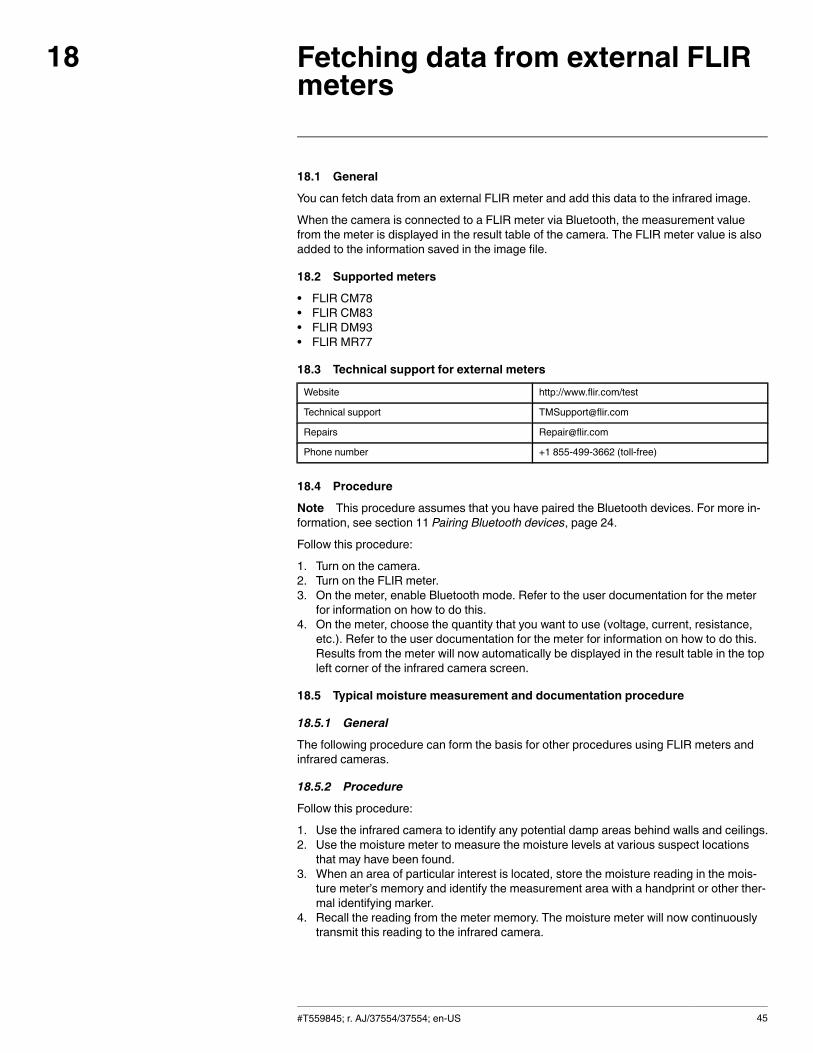
Fetching data from external FLIRmeters
18
18.1 General
You can fetch data from an external FLIR meter and add this data to the infrared image.
When the camera is connected to a FLIR meter via Bluetooth, the measurement valuefrom the meter is displayed in the result table of the camera. The FLIR meter value is alsoadded to the information saved in the image file.
18.2 Supported meters
• FLIR CM78• FLIR CM83• FLIR DM93• FLIR MR77
18.3 Technical support for external meters
Website http://www.flir.com/test
Technical support [email protected]
Repairs [email protected]
Phone number +1 855-499-3662 (toll-free)
18.4 Procedure
Note This procedure assumes that you have paired the Bluetooth devices. For more in-formation, see section 11 Pairing Bluetooth devices, page 24.
Follow this procedure:
1. Turn on the camera.2. Turn on the FLIR meter.3. On the meter, enable Bluetooth mode. Refer to the user documentation for the meter
for information on how to do this.4. On the meter, choose the quantity that you want to use (voltage, current, resistance,
etc.). Refer to the user documentation for the meter for information on how to do this.Results from the meter will now automatically be displayed in the result table in the topleft corner of the infrared camera screen.
18.5 Typical moisture measurement and documentation procedure
18.5.1 General
The following procedure can form the basis for other procedures using FLIR meters andinfrared cameras.
18.5.2 Procedure
Follow this procedure:
1. Use the infrared camera to identify any potential damp areas behind walls and ceilings.2. Use the moisture meter to measure the moisture levels at various suspect locations
that may have been found.3. When an area of particular interest is located, store the moisture reading in the mois-
ture meter’s memory and identify the measurement area with a handprint or other ther-mal identifying marker.
4. Recall the reading from the meter memory. The moisture meter will now continuouslytransmit this reading to the infrared camera.
#T559845; r. AJ/37554/37554; en-US 45

Fetching data from external FLIR meters18
5. Use the camera to take a thermal image of the area with the identifying marker. Thestored data from the moisture meter will also be saved on the image.
#T559845; r. AJ/37554/37554; en-US 46
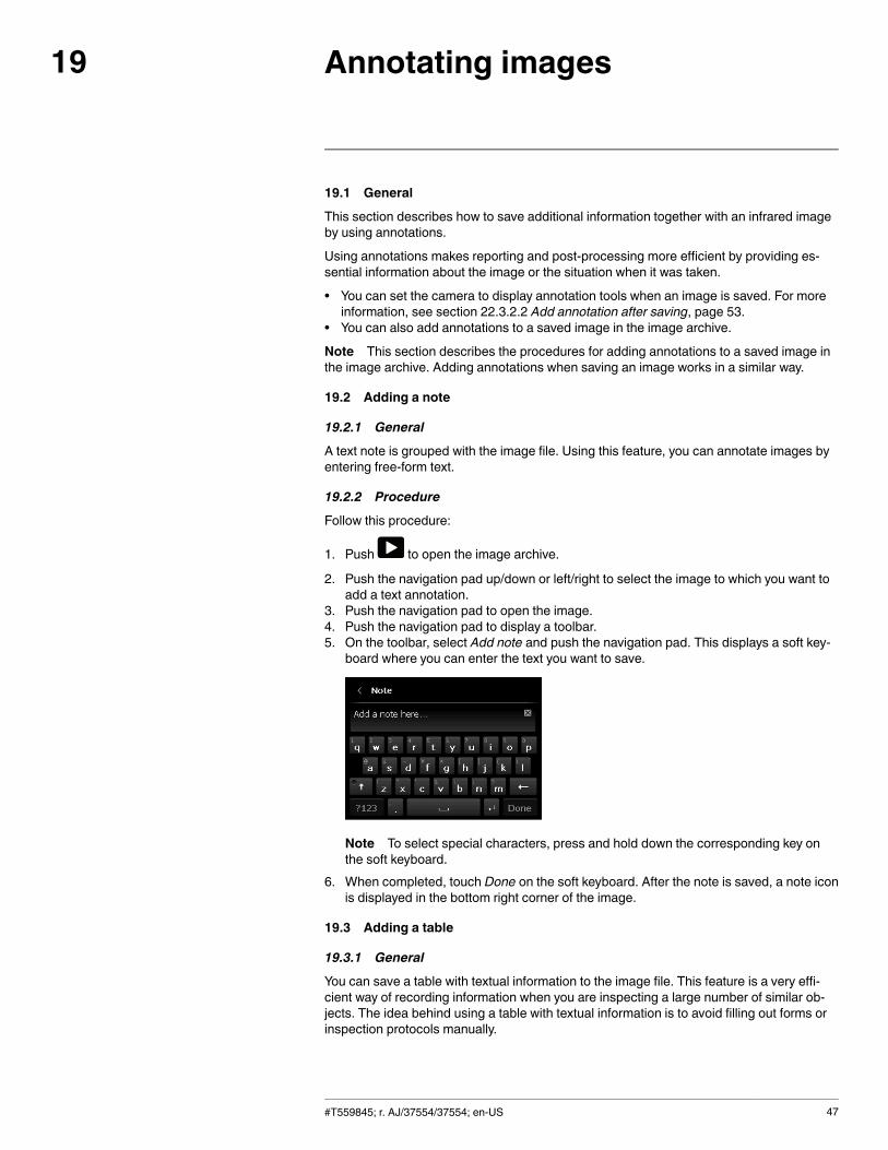
Annotating images19
19.1 General
This section describes how to save additional information together with an infrared imageby using annotations.
Using annotations makes reporting and post-processing more efficient by providing es-sential information about the image or the situation when it was taken.
• You can set the camera to display annotation tools when an image is saved. For moreinformation, see section 22.3.2.2 Add annotation after saving, page 53.
• You can also add annotations to a saved image in the image archive.
Note This section describes the procedures for adding annotations to a saved image inthe image archive. Adding annotations when saving an image works in a similar way.
19.2 Adding a note
19.2.1 General
A text note is grouped with the image file. Using this feature, you can annotate images byentering free-form text.
19.2.2 Procedure
Follow this procedure:
1. Push to open the image archive.
2. Push the navigation pad up/down or left/right to select the image to which you want toadd a text annotation.
3. Push the navigation pad to open the image.4. Push the navigation pad to display a toolbar.5. On the toolbar, select Add note and push the navigation pad. This displays a soft key-
board where you can enter the text you want to save.
Note To select special characters, press and hold down the corresponding key onthe soft keyboard.
6. When completed, touch Done on the soft keyboard. After the note is saved, a note iconis displayed in the bottom right corner of the image.
19.3 Adding a table
19.3.1 General
You can save a table with textual information to the image file. This feature is a very effi-cient way of recording information when you are inspecting a large number of similar ob-jects. The idea behind using a table with textual information is to avoid filling out forms orinspection protocols manually.
#T559845; r. AJ/37554/37554; en-US 47
Annotating images19
The camera has a number of default table templates. You can also import your own tabletemplates from FLIR Tools. The templates are stored on the memory card.
19.3.2 Procedure
Follow this procedure:
1. Push to open the image archive.2. Push the navigation pad up/down or left/right to select the image to which you want to
add a table annotation.3. Push the navigation pad to open the image.4. Push the navigation pad to display a toolbar.5. On the toolbar, select Add table and push the navigation pad.6. Select Add table contents and push the navigation pad. This displays the default
template.Note You can select another template by first selecting Select default template.
7. For each row in the table, do the following:
• Push the navigation pad. This displays the predefined values.• Push the navigation pad up/down to select a predefined value. Push the navigationpad to confirm.
• Instead of selecting a predefined value, you can select the keyboard and enterother text.
8. When completed, select Save & Exit at the bottom of the table. Push the navigationpad to confirm.
19.4 Adding a voice annotation
19.4.1 General
A voice annotation is an audio recording that is stored in an infrared image file.
The voice annotation is recorded using a Bluetooth headset. The recording can be playedback in the camera, and in image analysis and reporting software from FLIR Systems.
19.4.2 Procedure
Note This procedure assumes that you have paired the camera with a Bluetooth head-set. For information on how to do this, see section 11 Pairing Bluetooth devices, page 24.
Follow this procedure:
1. Push to open the image archive.
2. Push the navigation pad up/down or left/right to select the image to which you want toadd a voice annotation.
3. Push the navigation pad to open the image.4. Push the navigation pad to display a toolbar.5. On the toolbar, select Add voice annotation and push the navigation pad. This displays
a recording toolbar.6. Select Record and push the navigation pad to start a recording.7. Select Stop and push the navigation pad to stop the recording.8. Select Play and push the navigation pad to listen to the recording.9. Select Delete and push the navigation pad to delete the recording.10.When completed, select Done and push the navigation pad.
#T559845; r. AJ/37554/37554; en-US 48
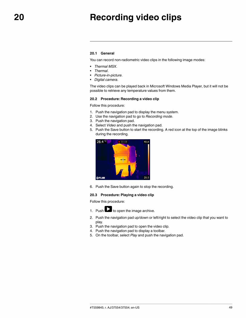
Recording video clips20
20.1 General
You can record non-radiometric video clips in the following image modes:
• Thermal MSX.• Thermal.• Picture-in-picture.• Digital camera.
The video clips can be played back in Microsoft Windows Media Player, but it will not bepossible to retrieve any temperature values from them.
20.2 Procedure: Recording a video clip
Follow this procedure:
1. Push the navigation pad to display the menu system.2. Use the navigation pad to go to Recording mode.3. Push the navigation pad.4. Select Video and push the navigation pad.5. Push the Save button to start the recording. A red icon at the top of the image blinks
during the recording.
6. Push the Save button again to stop the recording.
20.3 Procedure: Playing a video clip
Follow this procedure:
1. Push to open the image archive.
2. Push the navigation pad up/down or left/right to select the video clip that you want toplay.
3. Push the navigation pad to open the video clip.4. Push the navigation pad to display a toolbar.5. On the toolbar, select Play and push the navigation pad.
#T559845; r. AJ/37554/37554; en-US 49
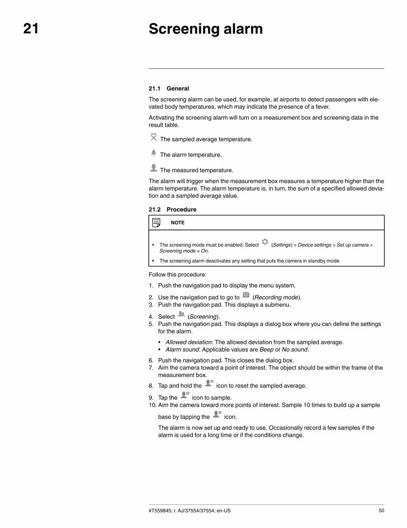
Screening alarm21
21.1 General
The screening alarm can be used, for example, at airports to detect passengers with ele-vated body temperatures, which may indicate the presence of a fever.
Activating the screening alarm will turn on a measurement box and screening data in theresult table.
The sampled average temperature.
The alarm temperature.
The measured temperature.
The alarm will trigger when the measurement box measures a temperature higher than thealarm temperature. The alarm temperature is, in turn, the sum of a specified allowed devia-tion and a sampled average value.
21.2 Procedure
NOTE
• The screening mode must be enabled. Select (Settings) > Device settings > Set up camera >Screening mode = On.
• The screening alarm deactivates any setting that puts the camera in standby mode.
Follow this procedure:
1. Push the navigation pad to display the menu system.
2. Use the navigation pad to go to (Recording mode).3. Push the navigation pad. This displays a submenu.
4. Select (Screening).5. Push the navigation pad. This displays a dialog box where you can define the settings
for the alarm.
• Allowed deviation: The allowed deviation from the sampled average.• Alarm sound: Applicable values are Beep or No sound.
6. Push the navigation pad. This closes the dialog box.7. Aim the camera toward a point of interest. The object should be within the frame of the
measurement box.8. Tap and hold the icon to reset the sampled average.
9. Tap the icon to sample.10. Aim the camera toward more points of interest. Sample 10 times to build up a sample
base by tapping the icon.
The alarm is now set up and ready to use. Occasionally record a few samples if thealarm is used for a long time or if the conditions change.
#T559845; r. AJ/37554/37554; en-US 50
Screening alarm21
NOTE
• The algorithm has a memory of the last 10 samples. It discriminates between the highest and lowestvalues, and calculates an average of the remaining values.
• Do not modify the measurement setup or activate another alarm because this will deactivate thescreening alarm.
#T559845; r. AJ/37554/37554; en-US 51
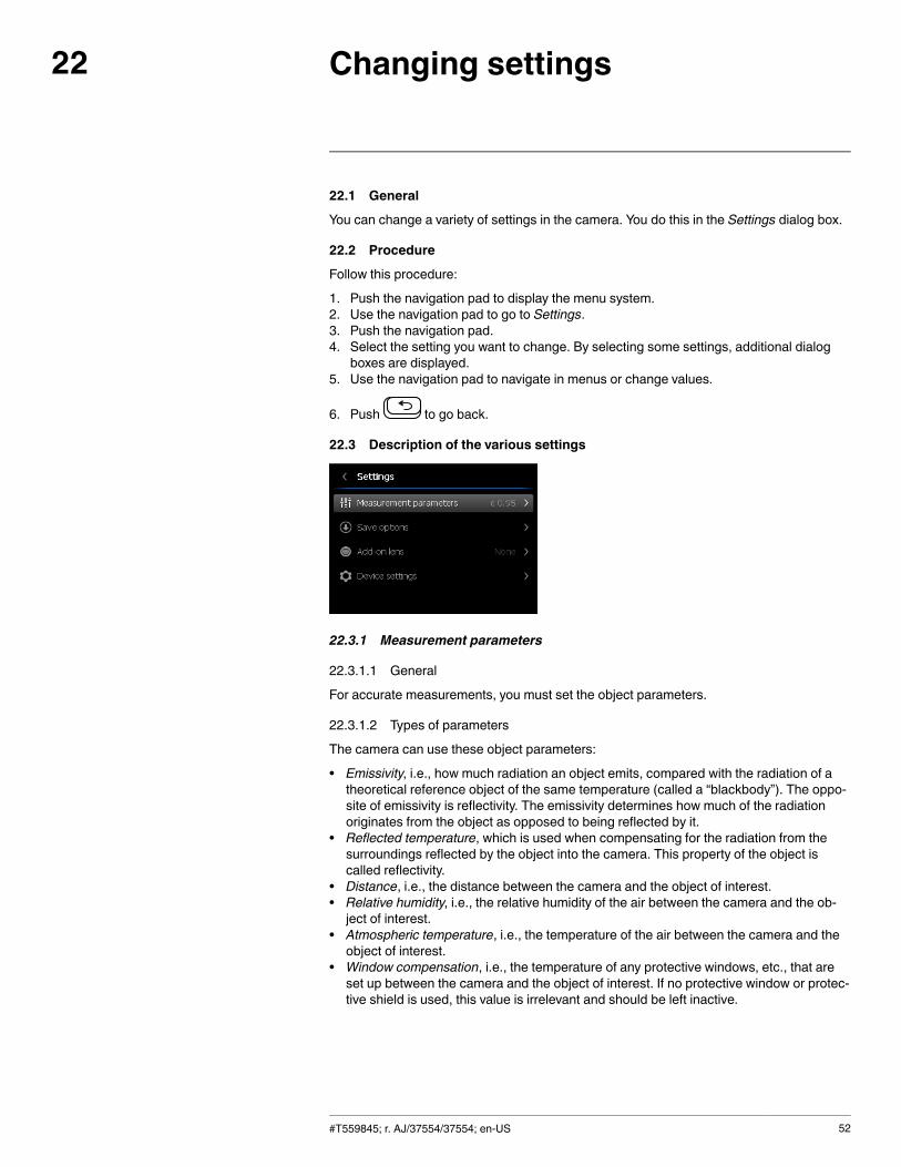
Changing settings22
22.1 General
You can change a variety of settings in the camera. You do this in the Settings dialog box.
22.2 Procedure
Follow this procedure:
1. Push the navigation pad to display the menu system.2. Use the navigation pad to go to Settings.3. Push the navigation pad.4. Select the setting you want to change. By selecting some settings, additional dialog
boxes are displayed.5. Use the navigation pad to navigate in menus or change values.
6. Push to go back.
22.3 Description of the various settings
22.3.1 Measurement parameters
22.3.1.1 General
For accurate measurements, you must set the object parameters.
22.3.1.2 Types of parameters
The camera can use these object parameters:
• Emissivity, i.e., how much radiation an object emits, compared with the radiation of atheoretical reference object of the same temperature (called a “blackbody”). The oppo-site of emissivity is reflectivity. The emissivity determines how much of the radiationoriginates from the object as opposed to being reflected by it.
• Reflected temperature, which is used when compensating for the radiation from thesurroundings reflected by the object into the camera. This property of the object iscalled reflectivity.
• Distance, i.e., the distance between the camera and the object of interest.• Relative humidity, i.e., the relative humidity of the air between the camera and the ob-ject of interest.
• Atmospheric temperature, i.e., the temperature of the air between the camera and theobject of interest.
• Window compensation, i.e., the temperature of any protective windows, etc., that areset up between the camera and the object of interest. If no protective window or protec-tive shield is used, this value is irrelevant and should be left inactive.
#T559845; r. AJ/37554/37554; en-US 52
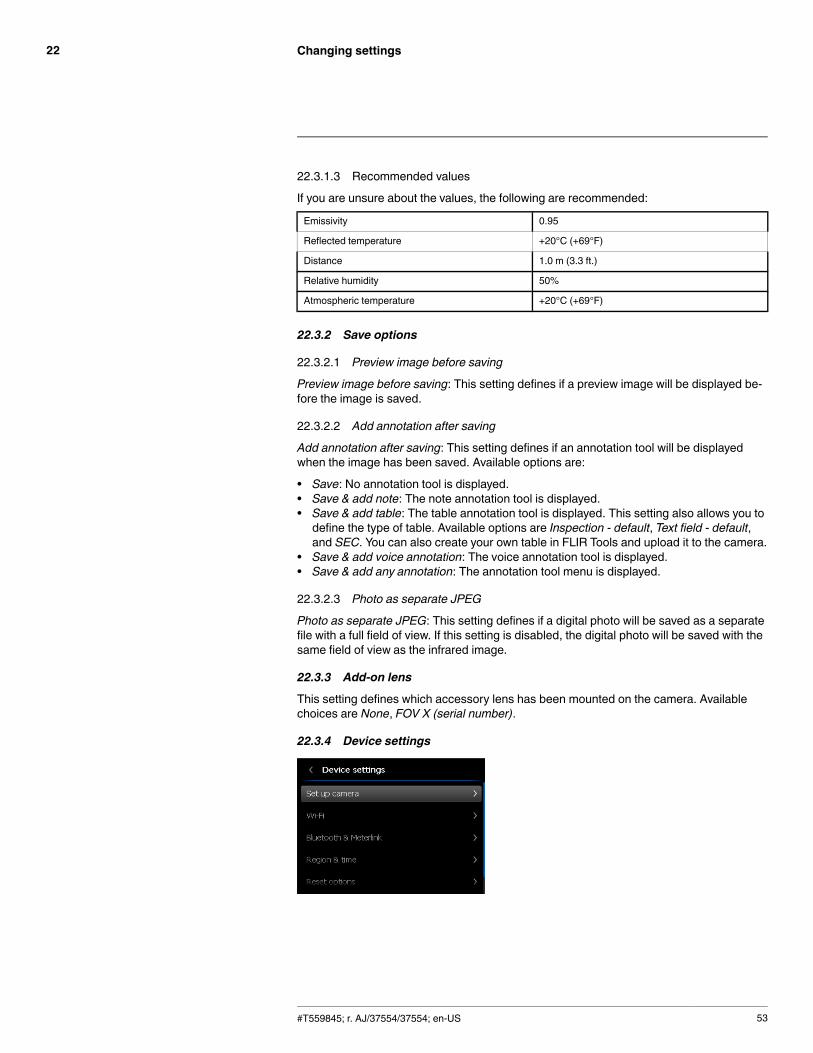
Changing settings22
22.3.1.3 Recommended values
If you are unsure about the values, the following are recommended:
Emissivity 0.95
Reflected temperature +20°C (+69°F)
Distance 1.0 m (3.3 ft.)
Relative humidity 50%
Atmospheric temperature +20°C (+69°F)
22.3.2 Save options
22.3.2.1 Preview image before saving
Preview image before saving: This setting defines if a preview image will be displayed be-fore the image is saved.
22.3.2.2 Add annotation after saving
Add annotation after saving: This setting defines if an annotation tool will be displayedwhen the image has been saved. Available options are:
• Save: No annotation tool is displayed.• Save & add note: The note annotation tool is displayed.• Save & add table: The table annotation tool is displayed. This setting also allows you todefine the type of table. Available options are Inspection - default, Text field - default,and SEC. You can also create your own table in FLIR Tools and upload it to the camera.
• Save & add voice annotation: The voice annotation tool is displayed.• Save & add any annotation: The annotation tool menu is displayed.
22.3.2.3 Photo as separate JPEG
Photo as separate JPEG: This setting defines if a digital photo will be saved as a separatefile with a full field of view. If this setting is disabled, the digital photo will be saved with thesame field of view as the infrared image.
22.3.3 Add-on lens
This setting defines which accessory lens has been mounted on the camera. Availablechoices are None, FOV X (serial number).
22.3.4 Device settings
#T559845; r. AJ/37554/37554; en-US 53
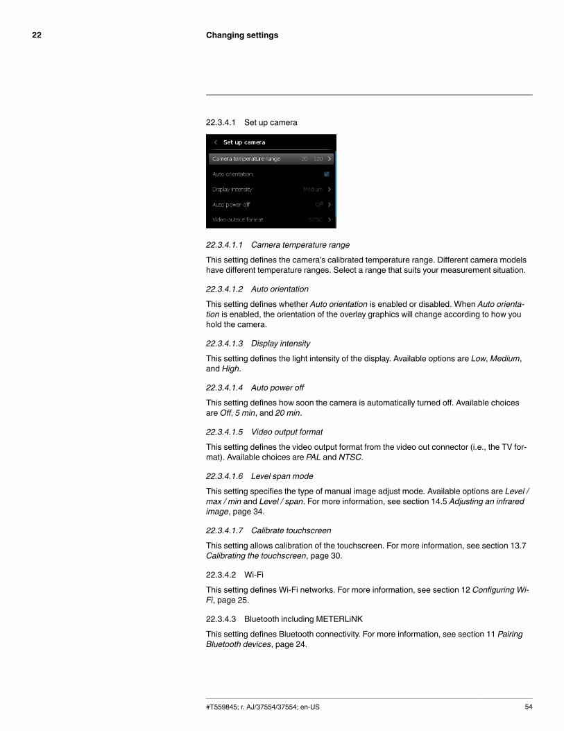
Changing settings22
22.3.4.1 Set up camera
22.3.4.1.1 Camera temperature range
This setting defines the camera’s calibrated temperature range. Different camera modelshave different temperature ranges. Select a range that suits your measurement situation.
22.3.4.1.2 Auto orientation
This setting defines whether Auto orientation is enabled or disabled. When Auto orienta-tion is enabled, the orientation of the overlay graphics will change according to how youhold the camera.
22.3.4.1.3 Display intensity
This setting defines the light intensity of the display. Available options are Low,Medium,and High.
22.3.4.1.4 Auto power off
This setting defines how soon the camera is automatically turned off. Available choicesare Off, 5 min, and 20 min.
22.3.4.1.5 Video output format
This setting defines the video output format from the video out connector (i.e., the TV for-mat). Available choices are PAL and NTSC.
22.3.4.1.6 Level span mode
This setting specifies the type of manual image adjust mode. Available options are Level /max / min and Level / span. For more information, see section 14.5 Adjusting an infraredimage, page 34.
22.3.4.1.7 Calibrate touchscreen
This setting allows calibration of the touchscreen. For more information, see section 13.7Calibrating the touchscreen, page 30.
22.3.4.2 Wi-Fi
This setting defines Wi-Fi networks. For more information, see section 12 Configuring Wi-Fi, page 25.
22.3.4.3 Bluetooth including METERLiNK
This setting defines Bluetooth connectivity. For more information, see section 11 PairingBluetooth devices, page 24.
#T559845; r. AJ/37554/37554; en-US 54
Changing settings22
22.3.4.4 Language, time, and units
This setting defines a number of regional parameters:
• Language.• Temperature unit.• Distance unit.• Date and time.• Date and time format.
22.3.4.5 Reset options
This setting defines a number or reset options:
• Reset default camera mode: This will affect color palettes and measurement tools.Saved images will not be affected.
• Reset device settings to factory default: This will affect all camera settings, including re-gional settings. Saved images will not be affected. The camera will be restarted.
• Delete all saved images: This setting will delete all saved images in the image archive.
22.3.4.6 Camera information
This dialog displays camera information such as the model, serial number, part number,and software version. No changes can be made.
#T559845; r. AJ/37554/37554; en-US 55

Technical data23
23.1 Online field-of-view calculator
Please visit http://support.flir.com and click the photo of the camera series for field-of-viewtables for all lens–camera combinations.
23.2 Note about technical data
FLIR Systems reserves the right to change specifications at any time without prior notice.Please check http://support.flir.com for latest changes.
23.3 Note about authoritative versions
The authoritative version of this publication is English. In the event of divergences due totranslation errors, the English text has precedence.
Any late changes are first implemented in English.
#T559845; r. AJ/37554/37554; en-US 56
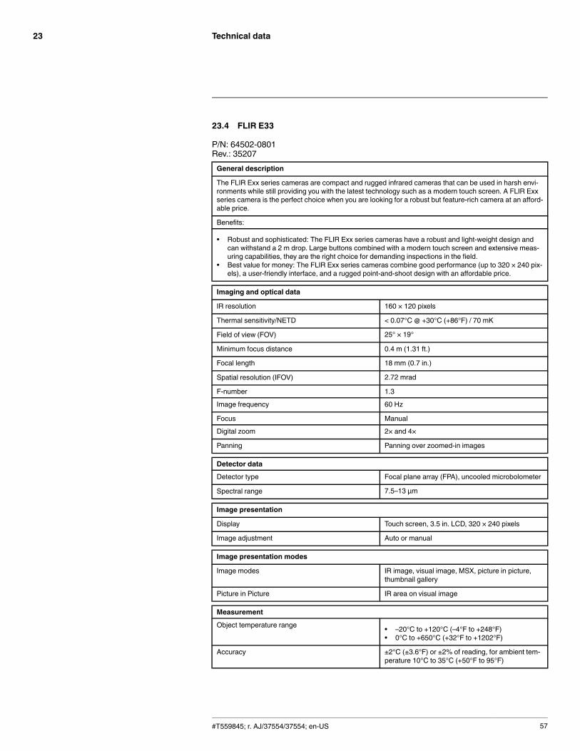
Technical data23
23.4 FLIR E33
P/N: 64502-0801Rev.: 35207General description
The FLIR Exx series cameras are compact and rugged infrared cameras that can be used in harsh envi-ronments while still providing you with the latest technology such as a modern touch screen. A FLIR Exxseries camera is the perfect choice when you are looking for a robust but feature-rich camera at an afford-able price.
Benefits:
• Robust and sophisticated: The FLIR Exx series cameras have a robust and light-weight design andcan withstand a 2 m drop. Large buttons combined with a modern touch screen and extensive meas-uring capabilities, they are the right choice for demanding inspections in the field.
• Best value for money: The FLIR Exx series cameras combine good performance (up to 320 × 240 pix-els), a user-friendly interface, and a rugged point-and-shoot design with an affordable price.
Imaging and optical data
IR resolution 160 × 120 pixels
Thermal sensitivity/NETD < 0.07°C @ +30°C (+86°F) / 70 mK
Field of view (FOV) 25° × 19°
Minimum focus distance 0.4 m (1.31 ft.)
Focal length 18 mm (0.7 in.)
Spatial resolution (IFOV) 2.72 mrad
F-number 1.3
Image frequency 60 Hz
Focus Manual
Digital zoom 2× and 4×
Panning Panning over zoomed-in images
Detector data
Detector type Focal plane array (FPA), uncooled microbolometer
Spectral range 7.5–13 µm
Image presentation
Display Touch screen, 3.5 in. LCD, 320 × 240 pixels
Image adjustment Auto or manual
Image presentation modes
Image modes IR image, visual image, MSX, picture in picture,thumbnail gallery
Picture in Picture IR area on visual image
Measurement
Object temperature range • –20°C to +120°C (–4°F to +248°F)• 0°C to +650°C (+32°F to +1202°F)
Accuracy ±2°C (±3.6°F) or ±2% of reading, for ambient tem-perature 10°C to 35°C (+50°F to 95°F)
#T559845; r. AJ/37554/37554; en-US 57

Technical data23
Measurement analysis
Spotmeter 3
Area Box with max./min./average
Automatic hot/cold detection Auto hot or cold spotmeter markers within area
Difference temperature Delta temperature between measurement func-tions or reference temperature
Reference temperature Manually set or captured from any measurementfunction
Emissivity correction Variable from 0.01 to 1.0 or selected from materialslist
External optics/windows correction Automatic, based on inputs of optics/window trans-mission and temperature
Measurement corrections Reflected temperature, optics transmission and at-mospheric transmission
Set-up
Color palettes Arctic, Gray, Iron, Lava, Rainbow and Rainbow HC
Set-up commands Local adaptation of units, language, date and timeformats
Storage of images
Image storage Standard JPEG, including measurement data, onmemory card
Image storage mode Simultaneous storage of images in IR, visual andMSX
Image annotations
Text Text from predefined list or soft keyboard on touchscreen
Report generation • FLIR Tools software specifically designed toprovide an easy way to create inspection re-ports. It is available on the major platforms –Android, Windows, MacOS, and iOS.
Video recording in camera
Non-radiometric IR video recording MPEG-4 to memory card
Video streaming
Radiometric IR video streaming Full dynamic to PC using USB
Non-radiometric IR video streaming Uncompressed colorized video using USB
Digital camera
Built-in digital camera 3.1 Mpixels (2048 × 1536 pixels), and one LEDlight
Digital camera, focus Fixed focus
Built-in digital lens data FOV 53° × 41°
Digital camera, aspect ratio 4:3
Laser pointer
Laser Activated by dedicated button
Laser alignment Position is automatic displayed on the IR image
#T559845; r. AJ/37554/37554; en-US 58

Technical data23
Laser pointer
Laser classification Class 2
Laser type Semiconductor AlGaInP diode laser
Laser power 1 mW
Laser wavelength 635 nm (red)
Data communication interfaces
SD Card One card slot for removable SD memory cards
USB
USB • USB-A: Connect external USB device• USB Mini-B: Data transfer to and from PC / un-
compressed colorized video
USB, standard USB Mini-B: 2.0
USB, connector type • USB-A connector• USB Mini-B connector
Composite video
Video out Composite
Video, standard CVBS (ITU-R-BT.470 PAL/SMPTE 170M NTSC)
Video, connector type 4-pole 3.5 mm jack
Power system
Battery type Rechargeable Li ion battery
Battery voltage 3.7 V
Battery capacity 4.4 Ah, at +20°C to +25°C (+68°F to +77°F)
Battery operating time Approx. 4 hours at +25°C (+77°F) ambient temper-ature and typical use
Charging system In camera (AC adapter or 12 V from a vehicle) or 2-bay charger
Charging time 4 h to 90% capacity, charging status indicated byLED's
Charging temperature 0°C to +45°C (+32°F to +113°F)
Power management Automatic shutdown and sleep mode (userselectable)
AC operation AC adapter, 90–260 VAC input, 12 V output tocamera
Start-up time from sleep mode Instant on
Environmental data
Operating temperature range –15°C to +50°C (+5°F to +122°F)
Storage temperature range –40°C to +70°C (–40°F to +158°F)
Humidity (operating and storage) IEC 60068-2-30/24 h 95% relative humidity +25°Cto +40°C (+77°F to +104°F) / 2 cycles
EMC • EN 61000-6-2 (Immunity)• EN 61000-6-3 (Emission)• FCC 47 CFR Part 15 B (Emission)
#T559845; r. AJ/37554/37554; en-US 59

Technical data23
Environmental data
Magnetic fields EN 61 000-4-8, Test level 5 for continuous field (se-vere industrial environment)
Encapsulation IP 54 (IEC 60529)
Shock 25 g (IEC 60068-2-27)
Vibration 2 g (IEC 60068-2-6)
Drop 2 m (6.6 ft.)
Safety EN/UL/CSA/PSE 60950-1
Physical data
Camera weight, incl. battery 0.869 kg (1.91 lb.)
Camera size (L × W × H) 246 × 97 × 184 mm (9.7 × 3.8 × 7.2 in.)
Tripod mounting UNC ¼"-20 (adapter needed)
Material • Polycarbonate + acrylonitrile butadiene styrene(PC-ABS)
• Thixomold magnesium• Thermoplastic elastomer (TPE)
Color Graphite gray and black
Shipping information
Packaging, type Cardboard box
List of contents • Hard transport case• Infrared camera with lens• Battery• Handstrap• Memory card• Power supply, incl. multi-plugs• Printed documentation• USB cable• Video cable
Packaging, weight 5.2 kg (11.5 lb.)
Packaging, size 500 × 190 × 370 mm (19.7 × 7.5 × 14.6 in.)
EAN-13 4743254001206
UPC-12 845188005238
Country of origin Estonia
Supplies & accessories:
• 1196961; IR lens, f = 30 mm, 15° incl. case• 1196960; IR lens, f = 10 mm, 45° incl. case• T910814; Power supply, incl. multi plugs• T911230ACC; Memory card SDHC 4 GB• 1910423; USB cable Std A <-> Mini-B• T198509; Cigarette lighter adapter kit, 12 VDC, 1.2 m/3.9 ft.• 1910582ACC; Video cable• T911093; Tool belt• T198125; Battery charger, incl. power supply with multi plugs (Exx, Kxx)• T199235; High-temperature lens• T198113; IR lens, 76 mm (6°) with case and mounting support for Exx• T198487; Li-Ion Battery pack 3.7V 17Wh• T198484; Pouch for FLIR Exx series
#T559845; r. AJ/37554/37554; en-US 60

Technical data23
• T198485; Sun shield• T198341ACC; Transport case Exx• T198486; Tripod Adapter• T199363ACC; Battery Li-ion 3.6 V, 5.2 Ah, 19 Wh• 19250-100; IR Window 2 in• 19251-100; IR Window 3 in.• 19252-100; IR Window 4 in.• 19250-200; SS IR Window 2 in.• 19251-200; SS IR Window 3 in.• 19252-200; SS IR Window 4 in.• T198586; FLIR Reporter Professional (license only)• T198584; FLIR Tools• T198583; FLIR Tools+ (download card incl. license key)• DSW-10000; FLIR IR Camera Player• T198697; FLIR ResearchIR Max + HSDR 4 (hardware sec. dev.)• T199014; FLIR ResearchIR Max + HSDR 4 (printed license key)• T199044; FLIR ResearchIR Max + HSDR 4 Upgrade (printed license key)• T198696; FLIR ResearchIR Max 4 (hardware sec. dev.)• T199013; FLIR ResearchIR Max 4 (printed license key)• T199043; FLIR ResearchIR Max 4 Upgrade (printed license key)• T198731; FLIR ResearchIR Standard 4 (hardware sec. dev.)• T199012; FLIR ResearchIR Standard 4 (printed license key)• T199042; FLIR ResearchIR Standard 4 Upgrade (printed license key)• T199233; FLIR Atlas SDK for .NET• T199234; FLIR Atlas SDK for MATLAB
#T559845; r. AJ/37554/37554; en-US 61

Technical data23
23.5 FLIR E40
P/N: 64502-1001Rev.: 35207General description
The FLIR Exx series cameras are compact and rugged infrared cameras that can be used in harsh envi-ronments while still providing you with the latest technology such as a modern touch screen. A FLIR Exxseries camera is the perfect choice when you are looking for a robust but feature-rich camera at an afford-able price.
Benefits:
• Robust and sophisticated: The FLIR Exx series cameras have a robust and light-weight design andcan withstand a 2 m drop. Large buttons combined with a modern touch screen and extensive meas-uring capabilities, they are the right choice for demanding inspections in the field.
• Best value for money: The FLIR Exx series cameras combine good performance (up to 320 × 240 pix-els), a user-friendly interface, and a rugged point-and-shoot design with an affordable price.
Imaging and optical data
IR resolution 160 × 120 pixels
Thermal sensitivity/NETD < 0.07°C @ +30°C (+86°F) / 70 mK
Field of view (FOV) 25° × 19°
Minimum focus distance 0.4 m (1.31 ft.)
Focal length 18 mm (0.7 in.)
Spatial resolution (IFOV) 2.72 mrad
F-number 1.3
Image frequency 60 Hz
Focus Manual
Digital zoom 2×
Panning Panning over zoomed-in images
Detector data
Detector type Focal plane array (FPA), uncooled microbolometer
Spectral range 7.5–13 µm
Image presentation
Display Touch screen, 3.5 in. LCD, 320 × 240 pixels
Image adjustment Auto or manual
Image presentation modes
Image modes IR image, visual image, MSX, picture in picture,thumbnail gallery
Picture in Picture IR area on visual image
Measurement
Object temperature range • –20°C to +120°C (–4°F to +248°F)• 0°C to +650°C (+32°F to +1202°F)
Accuracy ±2°C (±3.6°F) or ±2% of reading, for ambient tem-perature 10°C to 35°C (+50°F to 95°F)
#T559845; r. AJ/37554/37554; en-US 62
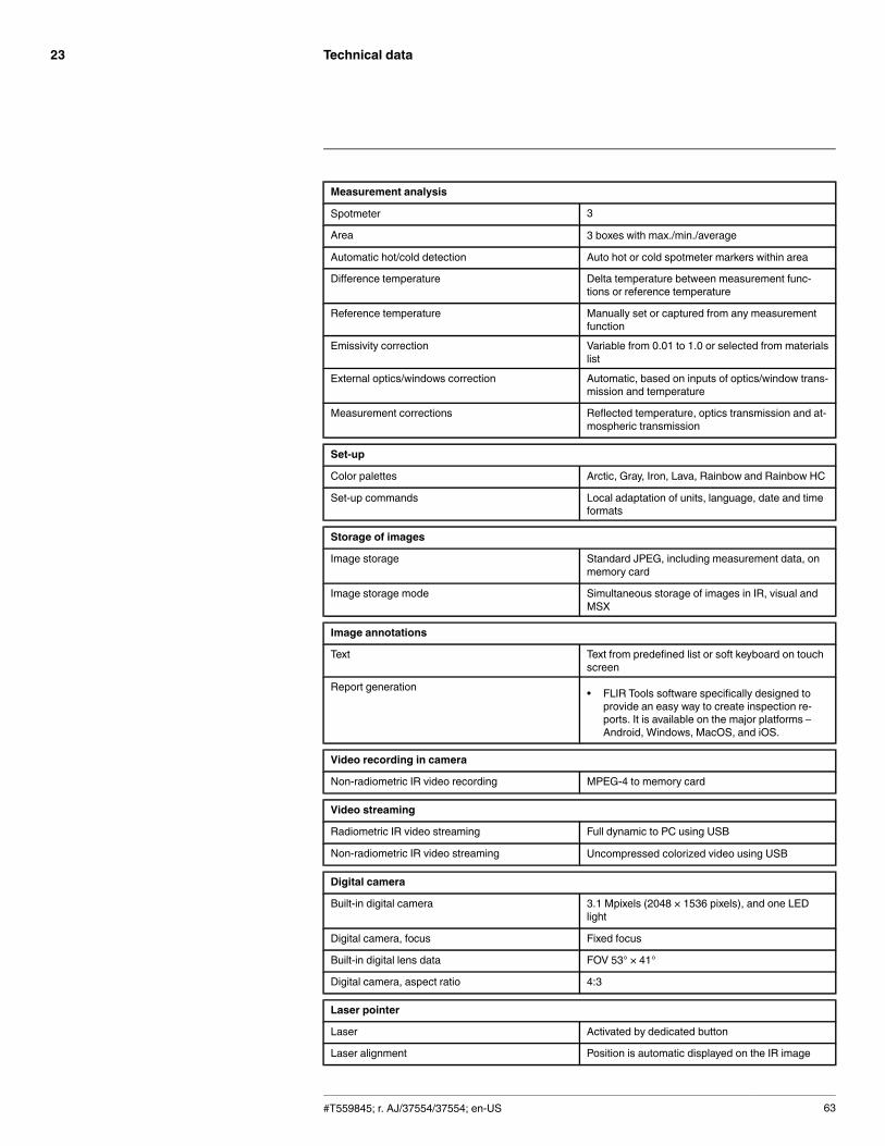
Technical data23
Measurement analysis
Spotmeter 3
Area 3 boxes with max./min./average
Automatic hot/cold detection Auto hot or cold spotmeter markers within area
Difference temperature Delta temperature between measurement func-tions or reference temperature
Reference temperature Manually set or captured from any measurementfunction
Emissivity correction Variable from 0.01 to 1.0 or selected from materialslist
External optics/windows correction Automatic, based on inputs of optics/window trans-mission and temperature
Measurement corrections Reflected temperature, optics transmission and at-mospheric transmission
Set-up
Color palettes Arctic, Gray, Iron, Lava, Rainbow and Rainbow HC
Set-up commands Local adaptation of units, language, date and timeformats
Storage of images
Image storage Standard JPEG, including measurement data, onmemory card
Image storage mode Simultaneous storage of images in IR, visual andMSX
Image annotations
Text Text from predefined list or soft keyboard on touchscreen
Report generation • FLIR Tools software specifically designed toprovide an easy way to create inspection re-ports. It is available on the major platforms –Android, Windows, MacOS, and iOS.
Video recording in camera
Non-radiometric IR video recording MPEG-4 to memory card
Video streaming
Radiometric IR video streaming Full dynamic to PC using USB
Non-radiometric IR video streaming Uncompressed colorized video using USB
Digital camera
Built-in digital camera 3.1 Mpixels (2048 × 1536 pixels), and one LEDlight
Digital camera, focus Fixed focus
Built-in digital lens data FOV 53° × 41°
Digital camera, aspect ratio 4:3
Laser pointer
Laser Activated by dedicated button
Laser alignment Position is automatic displayed on the IR image
#T559845; r. AJ/37554/37554; en-US 63
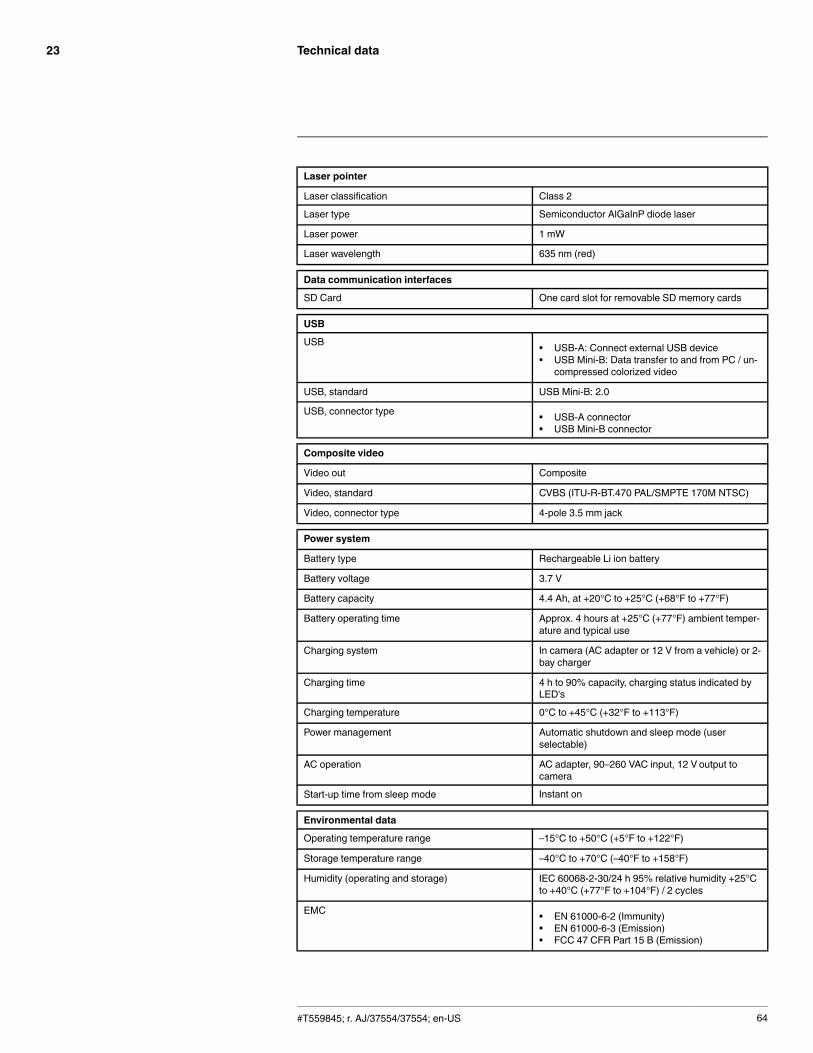
Technical data23
Laser pointer
Laser classification Class 2
Laser type Semiconductor AlGaInP diode laser
Laser power 1 mW
Laser wavelength 635 nm (red)
Data communication interfaces
SD Card One card slot for removable SD memory cards
USB
USB • USB-A: Connect external USB device• USB Mini-B: Data transfer to and from PC / un-
compressed colorized video
USB, standard USB Mini-B: 2.0
USB, connector type • USB-A connector• USB Mini-B connector
Composite video
Video out Composite
Video, standard CVBS (ITU-R-BT.470 PAL/SMPTE 170M NTSC)
Video, connector type 4-pole 3.5 mm jack
Power system
Battery type Rechargeable Li ion battery
Battery voltage 3.7 V
Battery capacity 4.4 Ah, at +20°C to +25°C (+68°F to +77°F)
Battery operating time Approx. 4 hours at +25°C (+77°F) ambient temper-ature and typical use
Charging system In camera (AC adapter or 12 V from a vehicle) or 2-bay charger
Charging time 4 h to 90% capacity, charging status indicated byLED's
Charging temperature 0°C to +45°C (+32°F to +113°F)
Power management Automatic shutdown and sleep mode (userselectable)
AC operation AC adapter, 90–260 VAC input, 12 V output tocamera
Start-up time from sleep mode Instant on
Environmental data
Operating temperature range –15°C to +50°C (+5°F to +122°F)
Storage temperature range –40°C to +70°C (–40°F to +158°F)
Humidity (operating and storage) IEC 60068-2-30/24 h 95% relative humidity +25°Cto +40°C (+77°F to +104°F) / 2 cycles
EMC • EN 61000-6-2 (Immunity)• EN 61000-6-3 (Emission)• FCC 47 CFR Part 15 B (Emission)
#T559845; r. AJ/37554/37554; en-US 64
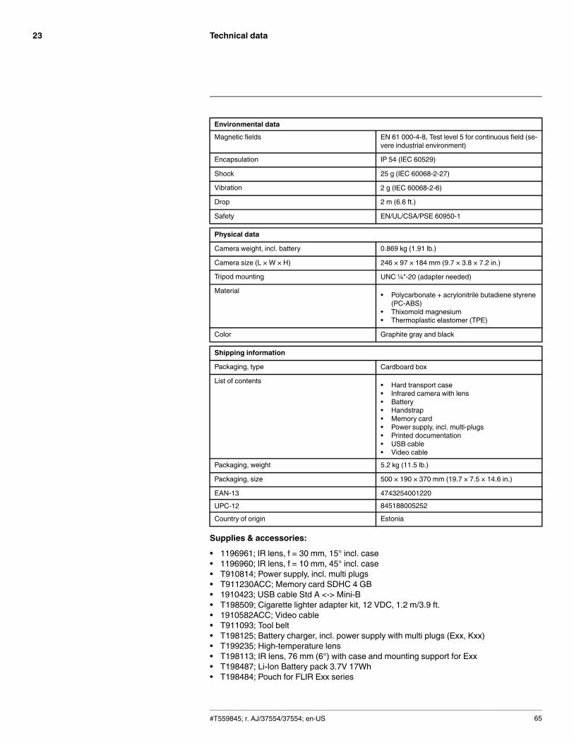
Technical data23
Environmental data
Magnetic fields EN 61 000-4-8, Test level 5 for continuous field (se-vere industrial environment)
Encapsulation IP 54 (IEC 60529)
Shock 25 g (IEC 60068-2-27)
Vibration 2 g (IEC 60068-2-6)
Drop 2 m (6.6 ft.)
Safety EN/UL/CSA/PSE 60950-1
Physical data
Camera weight, incl. battery 0.869 kg (1.91 lb.)
Camera size (L × W × H) 246 × 97 × 184 mm (9.7 × 3.8 × 7.2 in.)
Tripod mounting UNC ¼"-20 (adapter needed)
Material • Polycarbonate + acrylonitrile butadiene styrene(PC-ABS)
• Thixomold magnesium• Thermoplastic elastomer (TPE)
Color Graphite gray and black
Shipping information
Packaging, type Cardboard box
List of contents • Hard transport case• Infrared camera with lens• Battery• Handstrap• Memory card• Power supply, incl. multi-plugs• Printed documentation• USB cable• Video cable
Packaging, weight 5.2 kg (11.5 lb.)
Packaging, size 500 × 190 × 370 mm (19.7 × 7.5 × 14.6 in.)
EAN-13 4743254001220
UPC-12 845188005252
Country of origin Estonia
Supplies & accessories:
• 1196961; IR lens, f = 30 mm, 15° incl. case• 1196960; IR lens, f = 10 mm, 45° incl. case• T910814; Power supply, incl. multi plugs• T911230ACC; Memory card SDHC 4 GB• 1910423; USB cable Std A <-> Mini-B• T198509; Cigarette lighter adapter kit, 12 VDC, 1.2 m/3.9 ft.• 1910582ACC; Video cable• T911093; Tool belt• T198125; Battery charger, incl. power supply with multi plugs (Exx, Kxx)• T199235; High-temperature lens• T198113; IR lens, 76 mm (6°) with case and mounting support for Exx• T198487; Li-Ion Battery pack 3.7V 17Wh• T198484; Pouch for FLIR Exx series
#T559845; r. AJ/37554/37554; en-US 65
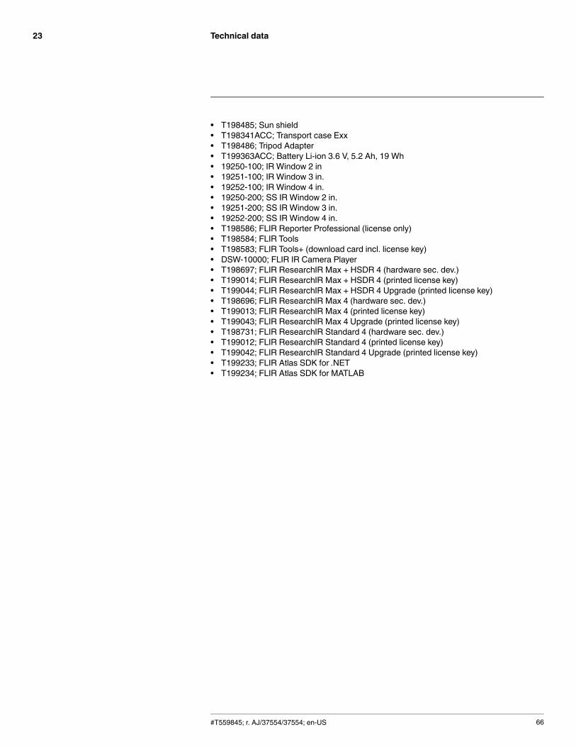
Technical data23
• T198485; Sun shield• T198341ACC; Transport case Exx• T198486; Tripod Adapter• T199363ACC; Battery Li-ion 3.6 V, 5.2 Ah, 19 Wh• 19250-100; IR Window 2 in• 19251-100; IR Window 3 in.• 19252-100; IR Window 4 in.• 19250-200; SS IR Window 2 in.• 19251-200; SS IR Window 3 in.• 19252-200; SS IR Window 4 in.• T198586; FLIR Reporter Professional (license only)• T198584; FLIR Tools• T198583; FLIR Tools+ (download card incl. license key)• DSW-10000; FLIR IR Camera Player• T198697; FLIR ResearchIR Max + HSDR 4 (hardware sec. dev.)• T199014; FLIR ResearchIR Max + HSDR 4 (printed license key)• T199044; FLIR ResearchIR Max + HSDR 4 Upgrade (printed license key)• T198696; FLIR ResearchIR Max 4 (hardware sec. dev.)• T199013; FLIR ResearchIR Max 4 (printed license key)• T199043; FLIR ResearchIR Max 4 Upgrade (printed license key)• T198731; FLIR ResearchIR Standard 4 (hardware sec. dev.)• T199012; FLIR ResearchIR Standard 4 (printed license key)• T199042; FLIR ResearchIR Standard 4 Upgrade (printed license key)• T199233; FLIR Atlas SDK for .NET• T199234; FLIR Atlas SDK for MATLAB
#T559845; r. AJ/37554/37554; en-US 66

Technical data23
23.6 FLIR E40 (incl. Wi-Fi)
P/N: 64501-0101Rev.: 35207General description
The FLIR Exx series cameras are compact and rugged infrared cameras that can be used in harsh envi-ronments while still providing you with the latest technology such as a modern touch screen and wirelessconnectivity. A FLIR Exx series camera is the perfect choice when you are looking for a robust but fea-ture-rich camera at an affordable price.
Benefits:
• Robust and sophisticated: The FLIR Exx series cameras have a robust and light-weight design andcan withstand a 2 m drop. Large buttons combined with a modern touch screen and extensive meas-uring capabilities, they are the right choice for demanding inspections in the field.
• Easy communication: The Wi-Fi connectivity of the FLIR Exx series cameras allows you to connect tosmart phones and tablets, for the wireless transfer of images or the remote control of the camera. TheBluetooth-based METERLiNK function transfers readings from external measurement instruments tothe infrared image.
• Best value for money: The FLIR Exx series cameras combine good performance (up to 320 × 240 pix-els), a user-friendly interface, and a rugged point-and-shoot design with an affordable price.
Imaging and optical data
IR resolution 160 × 120 pixels
Thermal sensitivity/NETD <0.07°C @ +30°C (+86°F) / 70 mK
Field of view (FOV) 25° × 19°
Minimum focus distance 0.4 m (1.31 ft.)
Focal length 18 mm (0.7 in.)
Spatial resolution (IFOV) 2.72 mrad
F-number 1.3
Image frequency 60 Hz
Focus Manual
Digital zoom 2×
Panning Panning over zoomed-in images
Detector data
Detector type Focal plane array (FPA), uncooled microbolometer
Spectral range 7.5–13 µm
Image presentation
Display Touch screen, 3.5 in. LCD, 320 × 240 pixels
Image adjustment Auto or manual
Image presentation modes
Image modes IR image, visual image, MSX, picture in picture,thumbnail gallery
Picture in Picture IR area on visual image
#T559845; r. AJ/37554/37554; en-US 67
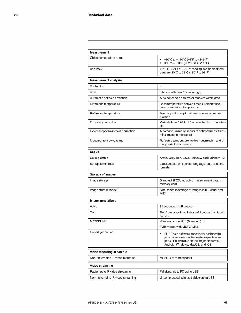
Technical data23
Measurement
Object temperature range • –20°C to +120°C (–4°F to +248°F)• 0°C to +650°C (+32°F to +1202°F)
Accuracy ±2°C (±3.6°F) or ±2% of reading, for ambient tem-perature 10°C to 35°C (+50°F to 95°F)
Measurement analysis
Spotmeter 3
Area 3 boxes with max./min./average
Automatic hot/cold detection Auto hot or cold spotmeter markers within area
Difference temperature Delta temperature between measurement func-tions or reference temperature
Reference temperature Manually set or captured from any measurementfunction
Emissivity correction Variable from 0.01 to 1.0 or selected from materialslist
External optics/windows correction Automatic, based on inputs of optics/window trans-mission and temperature
Measurement corrections Reflected temperature, optics transmission and at-mospheric transmission
Set-up
Color palettes Arctic, Gray, Iron, Lava, Rainbow and Rainbow HC
Set-up commands Local adaptation of units, language, date and timeformats
Storage of images
Image storage Standard JPEG, including measurement data, onmemory card
Image storage mode Simultaneous storage of images in IR, visual andMSX
Image annotations
Voice 60 seconds (via Bluetooth)
Text Text from predefined list or soft keyboard on touchscreen
METERLiNK Wireless connection (Bluetooth) to:
FLIR meters with METERLiNK
Report generation • FLIR Tools software specifically designed toprovide an easy way to create inspection re-ports. It is available on the major platforms –Android, Windows, MacOS, and iOS.
Video recording in camera
Non-radiometric IR video recording MPEG-4 to memory card
Video streaming
Radiometric IR video streaming Full dynamic to PC using USB
Non-radiometric IR video streaming Uncompressed colorized video using USB
#T559845; r. AJ/37554/37554; en-US 68
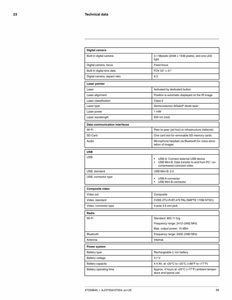
Technical data23
Digital camera
Built-in digital camera 3.1 Mpixels (2048 × 1536 pixels), and one LEDlight
Digital camera, focus Fixed focus
Built-in digital lens data FOV 53° × 41°
Digital camera, aspect ratio 4:3
Laser pointer
Laser Activated by dedicated button
Laser alignment Position is automatic displayed on the IR image
Laser classification Class 2
Laser type Semiconductor AlGaInP diode laser
Laser power 1 mW
Laser wavelength 635 nm (red)
Data communication interfaces
Wi-Fi Peer-to-peer (ad hoc) or infrastructure (network)
SD Card One card slot for removable SD memory cards
Audio Microphone headset via Bluetooth for voice anno-tation of images
USB
USB • USB-A: Connect external USB device• USB Mini-B: Data transfer to and from PC / un-
compressed colorized video
USB, standard USB Mini-B: 2.0
USB, connector type • USB-A connector• USB Mini-B connector
Composite video
Video out Composite
Video, standard CVBS (ITU-R-BT.470 PAL/SMPTE 170M NTSC)
Video, connector type 4-pole 3.5 mm jack
Radio
Wi-Fi Standard: 802.11 b/g
Frequency range: 2412–2462 MHz
Max. output power: 15 dBm
Bluetooth Frequency range: 2402–2480 MHz
Antenna Internal
Power system
Battery type Rechargeable Li ion battery
Battery voltage 3.7 V
Battery capacity 4.4 Ah, at +20°C to +25°C (+68°F to +77°F)
Battery operating time Approx. 4 hours at +25°C (+77°F) ambient temper-ature and typical use
#T559845; r. AJ/37554/37554; en-US 69

Technical data23
Power system
Charging system In camera (AC adapter or 12 V from a vehicle) or 2-bay charger
Charging time 4 h to 90% capacity, charging status indicated byLED's
Charging temperature 0°C to +45°C (+32°F to +113°F)
Power management Automatic shutdown and sleep mode (userselectable)
AC operation AC adapter, 90–260 VAC input, 12 V output tocamera
Start-up time from sleep mode Instant on
Environmental data
Operating temperature range –15°C to +50°C (+5°F to +122°F)
Storage temperature range –40°C to +70°C (–40°F to +158°F)
Humidity (operating and storage) IEC 60068-2-30/24 h 95% relative humidity +25°Cto +40°C (+77°F to +104°F) / 2 cycles
EMC • ETSI EN 301 489-1 (radio)• ETSI EN 301 489-17• EN 61000-6-2 (Immunity)• EN 61000-6-3 (Emission)• FCC 47 CFR Part 15 B (Emission)• ICES-003
Radio spectrum • ETSI EN 300 328• FCC Part 15.247• RSS-210
Magnetic fields EN 61 000-4-8, Test level 5 for continuous field (se-vere industrial environment)
Encapsulation IP 54 (IEC 60529)
Shock 25 g (IEC 60068-2-27)
Vibration 2 g (IEC 60068-2-6)
Drop 2 m (6.6 ft.)
Safety EN/UL/CSA/PSE 60950-1
Physical data
Camera weight, incl. battery 0.869 kg (1.91 lb.)
Camera size (L × W × H) 246 × 97 × 184 mm (9.7 × 3.8 × 7.2 in.)
Tripod mounting UNC ¼"-20 (adapter needed)
Material • Polycarbonate + acrylonitrile butadiene styrene(PC-ABS)
• Thixomold magnesium• Thermoplastic elastomer (TPE)
Color Graphite gray and black
#T559845; r. AJ/37554/37554; en-US 70

Technical data23
Shipping information
Packaging, type Cardboard box
List of contents • Hard transport case• Infrared camera with lens• Battery• Handstrap• Memory card• Power supply, incl. multi-plugs• Printed documentation• USB cable• Video cable
Packaging, weight 5.2 kg (11.5 lb.)
Packaging, size 500 × 190 × 370 mm (19.7 × 7.5 × 14.6 in.)
EAN-13 4743254001138
UPC-12 845188005160
Country of origin Estonia
Supplies & accessories:
• 1196961; IR lens, f = 30 mm, 15° incl. case• 1196960; IR lens, f = 10 mm, 45° incl. case• T910814; Power supply, incl. multi plugs• T911230ACC; Memory card SDHC 4 GB• 1910423; USB cable Std A <-> Mini-B• T198509; Cigarette lighter adapter kit, 12 VDC, 1.2 m/3.9 ft.• 1910582ACC; Video cable• T197771ACC; Bluetooth Headset• T911093; Tool belt• T198125; Battery charger, incl. power supply with multi plugs (Exx, Kxx)• T199235; High-temperature lens• T198113; IR lens, 76 mm (6°) with case and mounting support for Exx• T198487; Li-Ion Battery pack 3.7V 17Wh• T198484; Pouch for FLIR Exx series• T198485; Sun shield• T198341ACC; Transport case Exx• T198486; Tripod Adapter• T199363ACC; Battery Li-ion 3.6 V, 5.2 Ah, 19 Wh• 19250-100; IR Window 2 in• 19251-100; IR Window 3 in.• 19252-100; IR Window 4 in.• 19250-200; SS IR Window 2 in.• 19251-200; SS IR Window 3 in.• 19252-200; SS IR Window 4 in.• T198586; FLIR Reporter Professional (license only)• T198584; FLIR Tools• T198583; FLIR Tools+ (download card incl. license key)• DSW-10000; FLIR IR Camera Player• APP-10002; FLIR Tools Mobile (Android Application)• APP-10004; FLIR Tools (MacOS Application)• T198697; FLIR ResearchIR Max + HSDR 4 (hardware sec. dev.)• T199014; FLIR ResearchIR Max + HSDR 4 (printed license key)• T199044; FLIR ResearchIR Max + HSDR 4 Upgrade (printed license key)• T198696; FLIR ResearchIR Max 4 (hardware sec. dev.)• T199013; FLIR ResearchIR Max 4 (printed license key)
#T559845; r. AJ/37554/37554; en-US 71

Technical data23
• T199043; FLIR ResearchIR Max 4 Upgrade (printed license key)• T198731; FLIR ResearchIR Standard 4 (hardware sec. dev.)• T199012; FLIR ResearchIR Standard 4 (printed license key)• T199042; FLIR ResearchIR Standard 4 Upgrade (printed license key)• T199233; FLIR Atlas SDK for .NET• T199234; FLIR Atlas SDK for MATLAB
#T559845; r. AJ/37554/37554; en-US 72

Technical data23
23.7 FLIR E40 with SC kit (incl. Wi-Fi and 45° lens)
P/N: 64501-0103Rev.: 35207General description
The FLIR Exx series cameras are compact and rugged infrared cameras that can be used in harsh envi-ronments while still providing you with the latest technology such as a modern touch screen and wirelessconnectivity. A FLIR Exx series camera is the perfect choice when you are looking for a robust but fea-ture-rich camera at an affordable price.
Benefits:
• Robust and sophisticated: The FLIR Exx series cameras have a robust and light-weight design andcan withstand a 2 m drop. Large buttons combined with a modern touch screen and extensive meas-uring capabilities, they are the right choice for demanding inspections in the field.
• Easy communication: The Wi-Fi connectivity of the FLIR Exx series cameras allows you to connect tosmart phones and tablets, for the wireless transfer of images or the remote control of the camera. TheBluetooth-based METERLiNK function transfers readings from external measurement instruments tothe infrared image.
• Best value for money: The FLIR Exx series cameras combine good performance (up to 320 × 240 pix-els), a user-friendly interface, and a rugged point-and-shoot design with an affordable price.
Imaging and optical data
IR resolution 160 × 120 pixels
Thermal sensitivity/NETD < 0.07°C @ +30°C (+86°F) / 70 mK
Field of view (FOV) 25° × 19°
Minimum focus distance 0.4 m (1.31 ft.)
Focal length 18 mm (0.7 in.)
Spatial resolution (IFOV) 2.72 mrad
F-number 1.3
Image frequency 60 Hz
Focus Manual
Digital zoom 2×
Panning Panning over zoomed-in images
Detector data
Detector type Focal plane array (FPA), uncooled microbolometer
Spectral range 7.5–13 µm
Image presentation
Display Touch screen, 3.5 in. LCD, 320 × 240 pixels
Image adjustment Auto or manual
Image presentation modes
Image modes IR image, visual image, MSX, picture in picture,thumbnail gallery
Picture in Picture IR area on visual image
#T559845; r. AJ/37554/37554; en-US 73
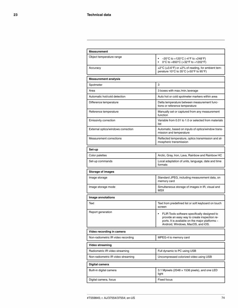
Technical data23
Measurement
Object temperature range • –20°C to +120°C (–4°F to +248°F)• 0°C to +650°C (+32°F to +1202°F)
Accuracy ±2°C (±3.6°F) or ±2% of reading, for ambient tem-perature 10°C to 35°C (+50°F to 95°F)
Measurement analysis
Spotmeter 3
Area 3 boxes with max./min./average
Automatic hot/cold detection Auto hot or cold spotmeter markers within area
Difference temperature Delta temperature between measurement func-tions or reference temperature
Reference temperature Manually set or captured from any measurementfunction
Emissivity correction Variable from 0.01 to 1.0 or selected from materialslist
External optics/windows correction Automatic, based on inputs of optics/window trans-mission and temperature
Measurement corrections Reflected temperature, optics transmission and at-mospheric transmission
Set-up
Color palettes Arctic, Gray, Iron, Lava, Rainbow and Rainbow HC
Set-up commands Local adaptation of units, language, date and timeformats
Storage of images
Image storage Standard JPEG, including measurement data, onmemory card
Image storage mode Simultaneous storage of images in IR, visual andMSX
Image annotations
Text Text from predefined list or soft keyboard on touchscreen
Report generation • FLIR Tools software specifically designed toprovide an easy way to create inspection re-ports. It is available on the major platforms –Android, Windows, MacOS, and iOS.
Video recording in camera
Non-radiometric IR video recording MPEG-4 to memory card
Video streaming
Radiometric IR video streaming Full dynamic to PC using USB
Non-radiometric IR video streaming Uncompressed colorized video using USB
Digital camera
Built-in digital camera 3.1 Mpixels (2048 × 1536 pixels), and one LEDlight
Digital camera, focus Fixed focus
#T559845; r. AJ/37554/37554; en-US 74

Technical data23
Digital camera
Built-in digital lens data FOV 53° × 41°
Digital camera, aspect ratio 4:3
Laser pointer
Laser Activated by dedicated button
Laser alignment Position is automatic displayed on the IR image
Laser classification Class 2
Laser type Semiconductor AlGaInP diode laser
Laser power 1 mW
Laser wavelength 635 nm (red)
Data communication interfaces
Wi-Fi Peer-to-peer (ad hoc) or infrastructure (network)
SD Card One card slot for removable SD memory cards
USB
USB • USB-A: Connect external USB device• USB Mini-B: Data transfer to and from PC / un-
compressed colorized video
USB, standard USB Mini-B: 2.0
USB, connector type • USB-A connector• USB Mini-B connector
Composite video
Video out Composite
Video, standard CVBS (ITU-R-BT.470 PAL/SMPTE 170M NTSC)
Video, connector type 4-pole 3.5 mm jack
Power system
Battery type Rechargeable Li ion battery
Battery voltage 3.7 V
Battery capacity 4.4 Ah, at +20°C to +25°C (+68°F to +77°F)
Battery operating time Approx. 4 hours at +25°C (+77°F) ambient temper-ature and typical use
Charging system In camera (AC adapter or 12 V from a vehicle) or 2-bay charger
Charging time 4 h to 90% capacity, charging status indicated byLED's
Charging temperature 0°C to +45°C (+32°F to +113°F)
Power management Automatic shutdown and sleep mode (userselectable)
AC operation AC adapter, 90–260 VAC input, 12 V output tocamera
Start-up time from sleep mode Instant on
#T559845; r. AJ/37554/37554; en-US 75
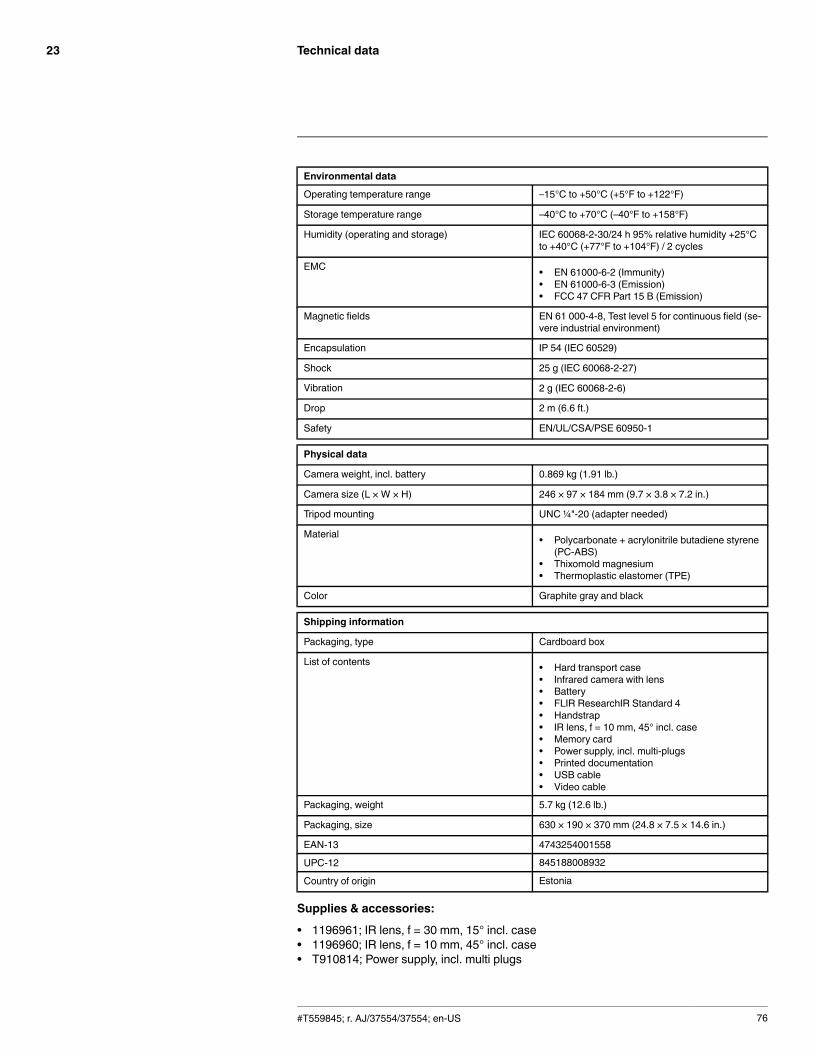
Technical data23
Environmental data
Operating temperature range –15°C to +50°C (+5°F to +122°F)
Storage temperature range –40°C to +70°C (–40°F to +158°F)
Humidity (operating and storage) IEC 60068-2-30/24 h 95% relative humidity +25°Cto +40°C (+77°F to +104°F) / 2 cycles
EMC • EN 61000-6-2 (Immunity)• EN 61000-6-3 (Emission)• FCC 47 CFR Part 15 B (Emission)
Magnetic fields EN 61 000-4-8, Test level 5 for continuous field (se-vere industrial environment)
Encapsulation IP 54 (IEC 60529)
Shock 25 g (IEC 60068-2-27)
Vibration 2 g (IEC 60068-2-6)
Drop 2 m (6.6 ft.)
Safety EN/UL/CSA/PSE 60950-1
Physical data
Camera weight, incl. battery 0.869 kg (1.91 lb.)
Camera size (L × W × H) 246 × 97 × 184 mm (9.7 × 3.8 × 7.2 in.)
Tripod mounting UNC ¼"-20 (adapter needed)
Material • Polycarbonate + acrylonitrile butadiene styrene(PC-ABS)
• Thixomold magnesium• Thermoplastic elastomer (TPE)
Color Graphite gray and black
Shipping information
Packaging, type Cardboard box
List of contents • Hard transport case• Infrared camera with lens• Battery• FLIR ResearchIR Standard 4• Handstrap• IR lens, f = 10 mm, 45° incl. case• Memory card• Power supply, incl. multi-plugs• Printed documentation• USB cable• Video cable
Packaging, weight 5.7 kg (12.6 lb.)
Packaging, size 630 × 190 × 370 mm (24.8 × 7.5 × 14.6 in.)
EAN-13 4743254001558
UPC-12 845188008932
Country of origin Estonia
Supplies & accessories:
• 1196961; IR lens, f = 30 mm, 15° incl. case• 1196960; IR lens, f = 10 mm, 45° incl. case• T910814; Power supply, incl. multi plugs
#T559845; r. AJ/37554/37554; en-US 76
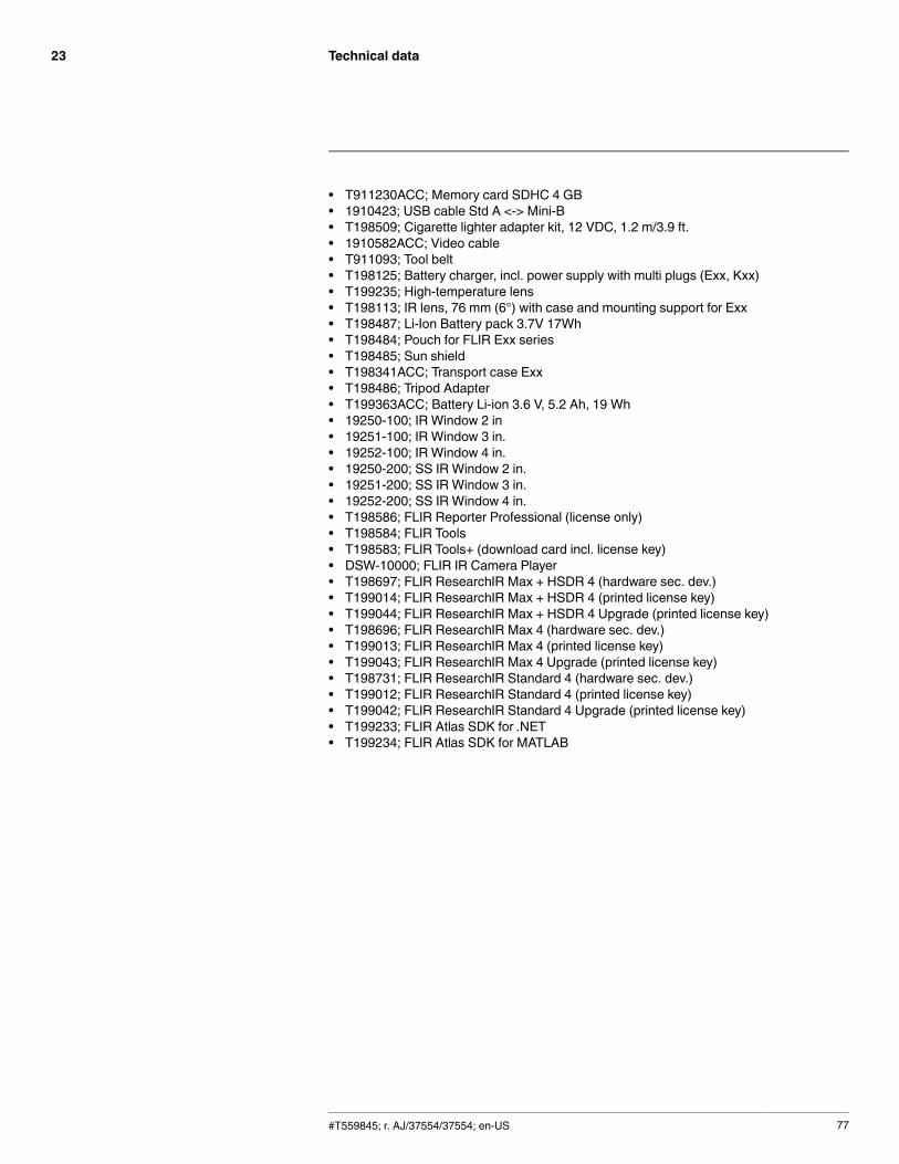
Technical data23
• T911230ACC; Memory card SDHC 4 GB• 1910423; USB cable Std A <-> Mini-B• T198509; Cigarette lighter adapter kit, 12 VDC, 1.2 m/3.9 ft.• 1910582ACC; Video cable• T911093; Tool belt• T198125; Battery charger, incl. power supply with multi plugs (Exx, Kxx)• T199235; High-temperature lens• T198113; IR lens, 76 mm (6°) with case and mounting support for Exx• T198487; Li-Ion Battery pack 3.7V 17Wh• T198484; Pouch for FLIR Exx series• T198485; Sun shield• T198341ACC; Transport case Exx• T198486; Tripod Adapter• T199363ACC; Battery Li-ion 3.6 V, 5.2 Ah, 19 Wh• 19250-100; IR Window 2 in• 19251-100; IR Window 3 in.• 19252-100; IR Window 4 in.• 19250-200; SS IR Window 2 in.• 19251-200; SS IR Window 3 in.• 19252-200; SS IR Window 4 in.• T198586; FLIR Reporter Professional (license only)• T198584; FLIR Tools• T198583; FLIR Tools+ (download card incl. license key)• DSW-10000; FLIR IR Camera Player• T198697; FLIR ResearchIR Max + HSDR 4 (hardware sec. dev.)• T199014; FLIR ResearchIR Max + HSDR 4 (printed license key)• T199044; FLIR ResearchIR Max + HSDR 4 Upgrade (printed license key)• T198696; FLIR ResearchIR Max 4 (hardware sec. dev.)• T199013; FLIR ResearchIR Max 4 (printed license key)• T199043; FLIR ResearchIR Max 4 Upgrade (printed license key)• T198731; FLIR ResearchIR Standard 4 (hardware sec. dev.)• T199012; FLIR ResearchIR Standard 4 (printed license key)• T199042; FLIR ResearchIR Standard 4 Upgrade (printed license key)• T199233; FLIR Atlas SDK for .NET• T199234; FLIR Atlas SDK for MATLAB
#T559845; r. AJ/37554/37554; en-US 77
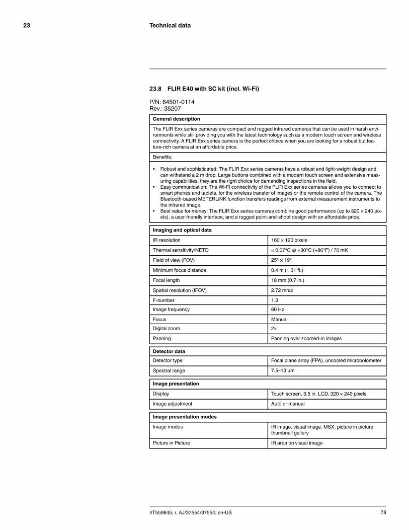
Technical data23
23.8 FLIR E40 with SC kit (incl. Wi-Fi)
P/N: 64501-0114Rev.: 35207General description
The FLIR Exx series cameras are compact and rugged infrared cameras that can be used in harsh envi-ronments while still providing you with the latest technology such as a modern touch screen and wirelessconnectivity. A FLIR Exx series camera is the perfect choice when you are looking for a robust but fea-ture-rich camera at an affordable price.
Benefits:
• Robust and sophisticated: The FLIR Exx series cameras have a robust and light-weight design andcan withstand a 2 m drop. Large buttons combined with a modern touch screen and extensive meas-uring capabilities, they are the right choice for demanding inspections in the field.
• Easy communication: The Wi-Fi connectivity of the FLIR Exx series cameras allows you to connect tosmart phones and tablets, for the wireless transfer of images or the remote control of the camera. TheBluetooth-based METERLiNK function transfers readings from external measurement instruments tothe infrared image.
• Best value for money: The FLIR Exx series cameras combine good performance (up to 320 × 240 pix-els), a user-friendly interface, and a rugged point-and-shoot design with an affordable price.
Imaging and optical data
IR resolution 160 × 120 pixels
Thermal sensitivity/NETD < 0.07°C @ +30°C (+86°F) / 70 mK
Field of view (FOV) 25° × 19°
Minimum focus distance 0.4 m (1.31 ft.)
Focal length 18 mm (0.7 in.)
Spatial resolution (IFOV) 2.72 mrad
F-number 1.3
Image frequency 60 Hz
Focus Manual
Digital zoom 2×
Panning Panning over zoomed-in images
Detector data
Detector type Focal plane array (FPA), uncooled microbolometer
Spectral range 7.5–13 µm
Image presentation
Display Touch screen, 3.5 in. LCD, 320 × 240 pixels
Image adjustment Auto or manual
Image presentation modes
Image modes IR image, visual image, MSX, picture in picture,thumbnail gallery
Picture in Picture IR area on visual image
#T559845; r. AJ/37554/37554; en-US 78

Technical data23
Measurement
Object temperature range • –20°C to +120°C (–4°F to +248°F)• 0°C to +650°C (+32°F to +1202°F)
Accuracy ±2°C (±3.6°F) or ±2% of reading, for ambient tem-perature 10°C to 35°C (+50°F to 95°F)
Measurement analysis
Spotmeter 3
Area 3 boxes with max./min./average
Automatic hot/cold detection Auto hot or cold spotmeter markers within area
Difference temperature Delta temperature between measurement func-tions or reference temperature
Reference temperature Manually set or captured from any measurementfunction
Emissivity correction Variable from 0.01 to 1.0 or selected from materialslist
External optics/windows correction Automatic, based on inputs of optics/window trans-mission and temperature
Measurement corrections Reflected temperature, optics transmission and at-mospheric transmission
Set-up
Color palettes Arctic, Gray, Iron, Lava, Rainbow and Rainbow HC
Set-up commands Local adaptation of units, language, date and timeformats
Storage of images
Image storage Standard JPEG, including measurement data, onmemory card
Image storage mode Simultaneous storage of images in IR, visual andMSX
Image annotations
Text Text from predefined list or soft keyboard on touchscreen
Report generation • FLIR Tools software specifically designed toprovide an easy way to create inspection re-ports. It is available on the major platforms –Android, Windows, MacOS, and iOS.
Video recording in camera
Non-radiometric IR video recording MPEG-4 to memory card
Video streaming
Radiometric IR video streaming Full dynamic to PC using USB
Non-radiometric IR video streaming Uncompressed colorized video using USB
Digital camera
Built-in digital camera 3.1 Mpixels (2048 × 1536 pixels), and one LEDlight
Digital camera, focus Fixed focus
#T559845; r. AJ/37554/37554; en-US 79
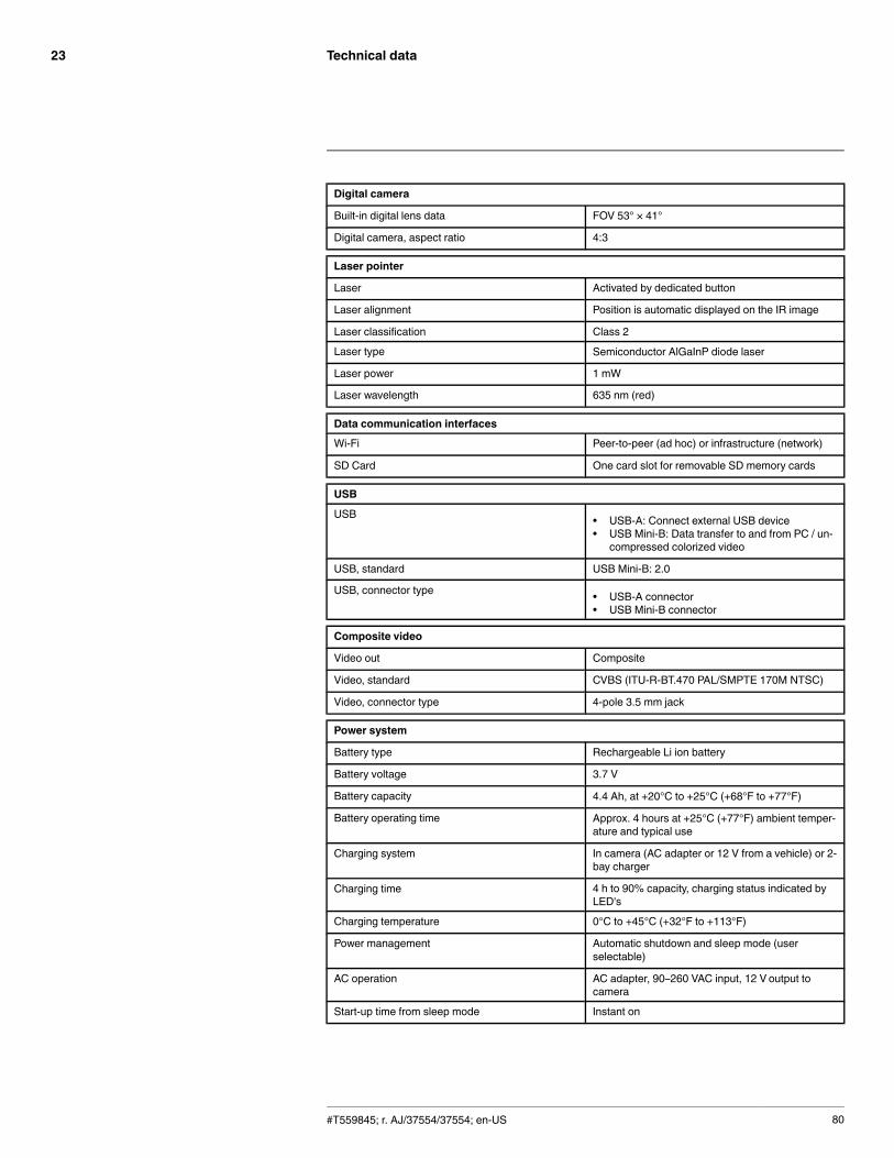
Technical data23
Digital camera
Built-in digital lens data FOV 53° × 41°
Digital camera, aspect ratio 4:3
Laser pointer
Laser Activated by dedicated button
Laser alignment Position is automatic displayed on the IR image
Laser classification Class 2
Laser type Semiconductor AlGaInP diode laser
Laser power 1 mW
Laser wavelength 635 nm (red)
Data communication interfaces
Wi-Fi Peer-to-peer (ad hoc) or infrastructure (network)
SD Card One card slot for removable SD memory cards
USB
USB • USB-A: Connect external USB device• USB Mini-B: Data transfer to and from PC / un-
compressed colorized video
USB, standard USB Mini-B: 2.0
USB, connector type • USB-A connector• USB Mini-B connector
Composite video
Video out Composite
Video, standard CVBS (ITU-R-BT.470 PAL/SMPTE 170M NTSC)
Video, connector type 4-pole 3.5 mm jack
Power system
Battery type Rechargeable Li ion battery
Battery voltage 3.7 V
Battery capacity 4.4 Ah, at +20°C to +25°C (+68°F to +77°F)
Battery operating time Approx. 4 hours at +25°C (+77°F) ambient temper-ature and typical use
Charging system In camera (AC adapter or 12 V from a vehicle) or 2-bay charger
Charging time 4 h to 90% capacity, charging status indicated byLED's
Charging temperature 0°C to +45°C (+32°F to +113°F)
Power management Automatic shutdown and sleep mode (userselectable)
AC operation AC adapter, 90–260 VAC input, 12 V output tocamera
Start-up time from sleep mode Instant on
#T559845; r. AJ/37554/37554; en-US 80
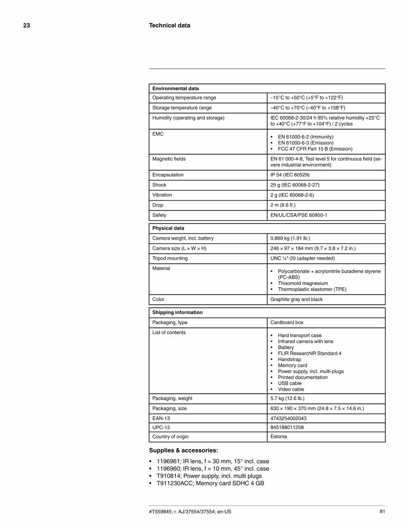
Technical data23
Environmental data
Operating temperature range –15°C to +50°C (+5°F to +122°F)
Storage temperature range –40°C to +70°C (–40°F to +158°F)
Humidity (operating and storage) IEC 60068-2-30/24 h 95% relative humidity +25°Cto +40°C (+77°F to +104°F) / 2 cycles
EMC • EN 61000-6-2 (Immunity)• EN 61000-6-3 (Emission)• FCC 47 CFR Part 15 B (Emission)
Magnetic fields EN 61 000-4-8, Test level 5 for continuous field (se-vere industrial environment)
Encapsulation IP 54 (IEC 60529)
Shock 25 g (IEC 60068-2-27)
Vibration 2 g (IEC 60068-2-6)
Drop 2 m (6.6 ft.)
Safety EN/UL/CSA/PSE 60950-1
Physical data
Camera weight, incl. battery 0.869 kg (1.91 lb.)
Camera size (L × W × H) 246 × 97 × 184 mm (9.7 × 3.8 × 7.2 in.)
Tripod mounting UNC ¼"-20 (adapter needed)
Material • Polycarbonate + acrylonitrile butadiene styrene(PC-ABS)
• Thixomold magnesium• Thermoplastic elastomer (TPE)
Color Graphite gray and black
Shipping information
Packaging, type Cardboard box
List of contents • Hard transport case• Infrared camera with lens• Battery• FLIR ResearchIR Standard 4• Handstrap• Memory card• Power supply, incl. multi-plugs• Printed documentation• USB cable• Video cable
Packaging, weight 5.7 kg (12.6 lb.)
Packaging, size 630 × 190 × 370 mm (24.8 × 7.5 × 14.6 in.)
EAN-13 4743254002043
UPC-12 845188011208
Country of origin Estonia
Supplies & accessories:
• 1196961; IR lens, f = 30 mm, 15° incl. case• 1196960; IR lens, f = 10 mm, 45° incl. case• T910814; Power supply, incl. multi plugs• T911230ACC; Memory card SDHC 4 GB
#T559845; r. AJ/37554/37554; en-US 81
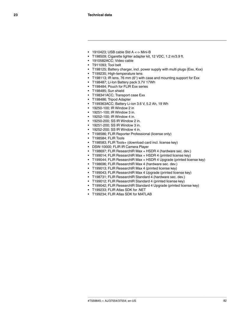
Technical data23
• 1910423; USB cable Std A <-> Mini-B• T198509; Cigarette lighter adapter kit, 12 VDC, 1.2 m/3.9 ft.• 1910582ACC; Video cable• T911093; Tool belt• T198125; Battery charger, incl. power supply with multi plugs (Exx, Kxx)• T199235; High-temperature lens• T198113; IR lens, 76 mm (6°) with case and mounting support for Exx• T198487; Li-Ion Battery pack 3.7V 17Wh• T198484; Pouch for FLIR Exx series• T198485; Sun shield• T198341ACC; Transport case Exx• T198486; Tripod Adapter• T199363ACC; Battery Li-ion 3.6 V, 5.2 Ah, 19 Wh• 19250-100; IR Window 2 in• 19251-100; IR Window 3 in.• 19252-100; IR Window 4 in.• 19250-200; SS IR Window 2 in.• 19251-200; SS IR Window 3 in.• 19252-200; SS IR Window 4 in.• T198586; FLIR Reporter Professional (license only)• T198584; FLIR Tools• T198583; FLIR Tools+ (download card incl. license key)• DSW-10000; FLIR IR Camera Player• T198697; FLIR ResearchIR Max + HSDR 4 (hardware sec. dev.)• T199014; FLIR ResearchIR Max + HSDR 4 (printed license key)• T199044; FLIR ResearchIR Max + HSDR 4 Upgrade (printed license key)• T198696; FLIR ResearchIR Max 4 (hardware sec. dev.)• T199013; FLIR ResearchIR Max 4 (printed license key)• T199043; FLIR ResearchIR Max 4 Upgrade (printed license key)• T198731; FLIR ResearchIR Standard 4 (hardware sec. dev.)• T199012; FLIR ResearchIR Standard 4 (printed license key)• T199042; FLIR ResearchIR Standard 4 Upgrade (printed license key)• T199233; FLIR Atlas SDK for .NET• T199234; FLIR Atlas SDK for MATLAB
#T559845; r. AJ/37554/37554; en-US 82
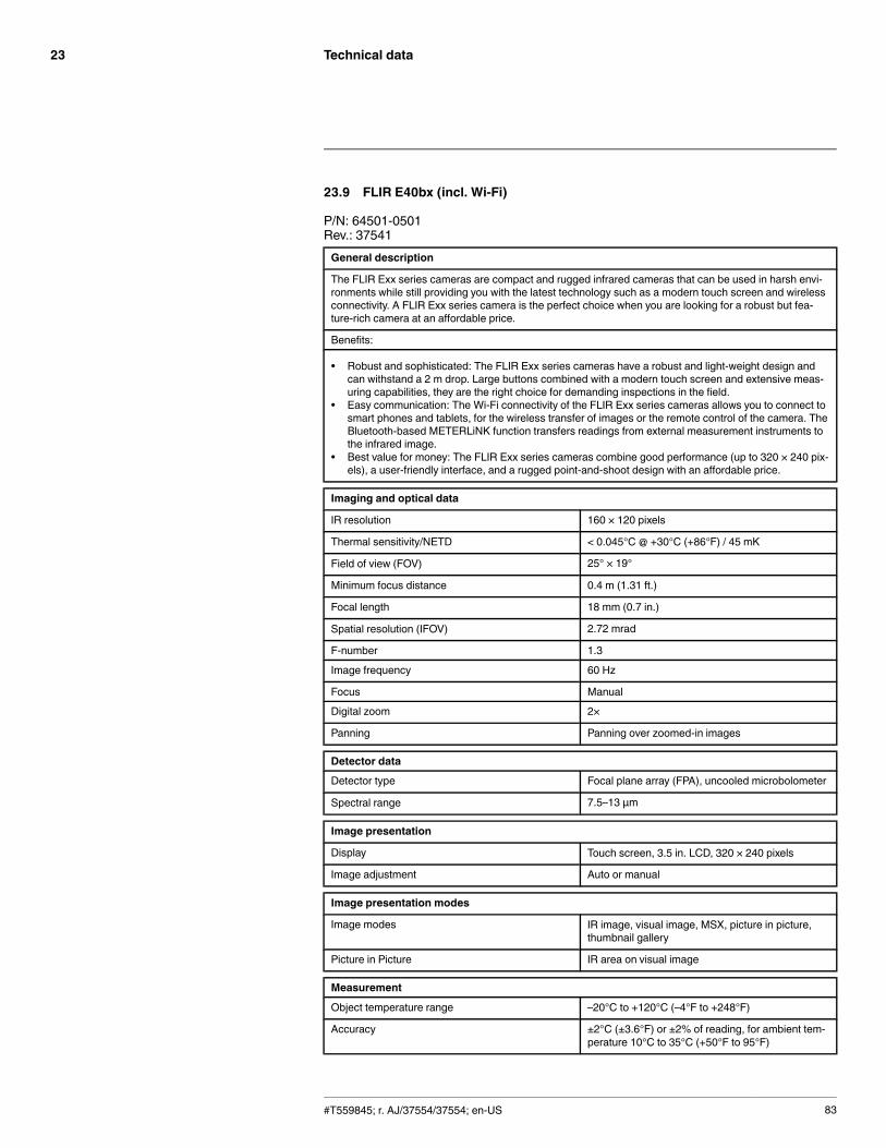
Technical data23
23.9 FLIR E40bx (incl. Wi-Fi)
P/N: 64501-0501Rev.: 37541General description
The FLIR Exx series cameras are compact and rugged infrared cameras that can be used in harsh envi-ronments while still providing you with the latest technology such as a modern touch screen and wirelessconnectivity. A FLIR Exx series camera is the perfect choice when you are looking for a robust but fea-ture-rich camera at an affordable price.
Benefits:
• Robust and sophisticated: The FLIR Exx series cameras have a robust and light-weight design andcan withstand a 2 m drop. Large buttons combined with a modern touch screen and extensive meas-uring capabilities, they are the right choice for demanding inspections in the field.
• Easy communication: The Wi-Fi connectivity of the FLIR Exx series cameras allows you to connect tosmart phones and tablets, for the wireless transfer of images or the remote control of the camera. TheBluetooth-based METERLiNK function transfers readings from external measurement instruments tothe infrared image.
• Best value for money: The FLIR Exx series cameras combine good performance (up to 320 × 240 pix-els), a user-friendly interface, and a rugged point-and-shoot design with an affordable price.
Imaging and optical data
IR resolution 160 × 120 pixels
Thermal sensitivity/NETD < 0.045°C @ +30°C (+86°F) / 45 mK
Field of view (FOV) 25° × 19°
Minimum focus distance 0.4 m (1.31 ft.)
Focal length 18 mm (0.7 in.)
Spatial resolution (IFOV) 2.72 mrad
F-number 1.3
Image frequency 60 Hz
Focus Manual
Digital zoom 2×
Panning Panning over zoomed-in images
Detector data
Detector type Focal plane array (FPA), uncooled microbolometer
Spectral range 7.5–13 µm
Image presentation
Display Touch screen, 3.5 in. LCD, 320 × 240 pixels
Image adjustment Auto or manual
Image presentation modes
Image modes IR image, visual image, MSX, picture in picture,thumbnail gallery
Picture in Picture IR area on visual image
Measurement
Object temperature range –20°C to +120°C (–4°F to +248°F)
Accuracy ±2°C (±3.6°F) or ±2% of reading, for ambient tem-perature 10°C to 35°C (+50°F to 95°F)
#T559845; r. AJ/37554/37554; en-US 83
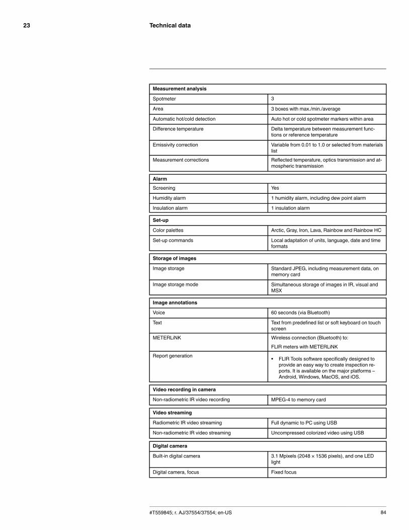
Technical data23
Measurement analysis
Spotmeter 3
Area 3 boxes with max./min./average
Automatic hot/cold detection Auto hot or cold spotmeter markers within area
Difference temperature Delta temperature between measurement func-tions or reference temperature
Emissivity correction Variable from 0.01 to 1.0 or selected from materialslist
Measurement corrections Reflected temperature, optics transmission and at-mospheric transmission
Alarm
Screening Yes
Humidity alarm 1 humidity alarm, including dew point alarm
Insulation alarm 1 insulation alarm
Set-up
Color palettes Arctic, Gray, Iron, Lava, Rainbow and Rainbow HC
Set-up commands Local adaptation of units, language, date and timeformats
Storage of images
Image storage Standard JPEG, including measurement data, onmemory card
Image storage mode Simultaneous storage of images in IR, visual andMSX
Image annotations
Voice 60 seconds (via Bluetooth)
Text Text from predefined list or soft keyboard on touchscreen
METERLiNK Wireless connection (Bluetooth) to:
FLIR meters with METERLiNK
Report generation • FLIR Tools software specifically designed toprovide an easy way to create inspection re-ports. It is available on the major platforms –Android, Windows, MacOS, and iOS.
Video recording in camera
Non-radiometric IR video recording MPEG-4 to memory card
Video streaming
Radiometric IR video streaming Full dynamic to PC using USB
Non-radiometric IR video streaming Uncompressed colorized video using USB
Digital camera
Built-in digital camera 3.1 Mpixels (2048 × 1536 pixels), and one LEDlight
Digital camera, focus Fixed focus
#T559845; r. AJ/37554/37554; en-US 84

Technical data23
Digital camera
Built-in digital lens data FOV 53° × 41°
Digital camera, aspect ratio 4:3
Laser pointer
Laser Activated by dedicated button
Laser alignment Position is automatic displayed on the IR image
Laser classification Class 2
Laser type Semiconductor AlGaInP diode laser
Laser power 1 mW
Laser wavelength 635 nm (red)
Data communication interfaces
Wi-Fi Peer to peer (ad hoc) or infrastructure (network)
SD Card One card slot for removable SD memory cards
Audio Microphone headset via Bluetooth for voice anno-tation of images
USB
USB • USB-A: Connect external USB device• USB Mini-B: Data transfer to and from PC / un-
compressed colorized video
USB, standard USB Mini-B: 2.0
USB, connector type • USB-A connector• USB Mini-B connector
Composite video
Video out Composite
Video, standard CVBS (ITU-R-BT.470 PAL/SMPTE 170M NTSC)
Video, connector type 4-pole 3.5 mm jack
Radio
Wi-Fi • Standard: 802.11 b/g• Frequency range: 2412–2462 MHz• Max. output power: 15 dBm
Bluetooth Frequency range: 2402–2480 MHz
Antenna Internal
Power system
Battery type Rechargeable Li ion battery
Battery voltage 3.7 V
Battery capacity 4.4 Ah, at +20°C to +25°C (+68°F to +77°F)
Battery operating time Approx. 4 hours at +25°C (+77°F) ambient temper-ature and typical use
Charging system In camera (AC adapter or 12 V from a vehicle) or 2-bay charger
Charging time 4 h to 90% capacity, charging status indicated byLED's
#T559845; r. AJ/37554/37554; en-US 85
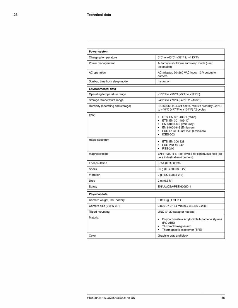
Technical data23
Power system
Charging temperature 0°C to +45°C (+32°F to +113°F)
Power management Automatic shutdown and sleep mode (userselectable)
AC operation AC adapter, 90–260 VAC input, 12 V output tocamera
Start-up time from sleep mode Instant on
Environmental data
Operating temperature range –15°C to +50°C (+5°F to +122°F)
Storage temperature range –40°C to +70°C (–40°F to +158°F)
Humidity (operating and storage) IEC 60068-2-30/24 h 95% relative humidity +25°Cto +40°C (+77°F to +104°F) / 2 cycles
EMC • ETSI EN 301 489-1 (radio)• ETSI EN 301 489-17• EN 61000-6-2 (Immunity)• EN 61000-6-3 (Emission)• FCC 47 CFR Part 15 B (Emission)• ICES-003
Radio spectrum • ETSI EN 300 328• FCC Part 15.247• RSS-210
Magnetic fields EN 61 000-4-8, Test level 5 for continuous field (se-vere industrial environment)
Encapsulation IP 54 (IEC 60529)
Shock 25 g (IEC 60068-2-27)
Vibration 2 g (IEC 60068-2-6)
Drop 2 m (6.6 ft.)
Safety EN/UL/CSA/PSE 60950-1
Physical data
Camera weight, incl. battery 0.869 kg (1.91 lb.)
Camera size (L × W × H) 246 × 97 × 184 mm (9.7 × 3.8 × 7.2 in.)
Tripod mounting UNC ¼"-20 (adapter needed)
Material • Polycarbonate + acrylonitrile butadiene styrene(PC-ABS)
• Thixomold magnesium• Thermoplastic elastomer (TPE)
Color Graphite gray and black
#T559845; r. AJ/37554/37554; en-US 86
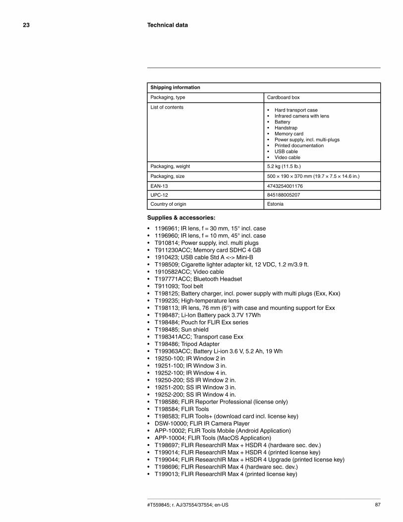
Technical data23
Shipping information
Packaging, type Cardboard box
List of contents • Hard transport case• Infrared camera with lens• Battery• Handstrap• Memory card• Power supply, incl. multi-plugs• Printed documentation• USB cable• Video cable
Packaging, weight 5.2 kg (11.5 lb.)
Packaging, size 500 × 190 × 370 mm (19.7 × 7.5 × 14.6 in.)
EAN-13 4743254001176
UPC-12 845188005207
Country of origin Estonia
Supplies & accessories:
• 1196961; IR lens, f = 30 mm, 15° incl. case• 1196960; IR lens, f = 10 mm, 45° incl. case• T910814; Power supply, incl. multi plugs• T911230ACC; Memory card SDHC 4 GB• 1910423; USB cable Std A <-> Mini-B• T198509; Cigarette lighter adapter kit, 12 VDC, 1.2 m/3.9 ft.• 1910582ACC; Video cable• T197771ACC; Bluetooth Headset• T911093; Tool belt• T198125; Battery charger, incl. power supply with multi plugs (Exx, Kxx)• T199235; High-temperature lens• T198113; IR lens, 76 mm (6°) with case and mounting support for Exx• T198487; Li-Ion Battery pack 3.7V 17Wh• T198484; Pouch for FLIR Exx series• T198485; Sun shield• T198341ACC; Transport case Exx• T198486; Tripod Adapter• T199363ACC; Battery Li-ion 3.6 V, 5.2 Ah, 19 Wh• 19250-100; IR Window 2 in• 19251-100; IR Window 3 in.• 19252-100; IR Window 4 in.• 19250-200; SS IR Window 2 in.• 19251-200; SS IR Window 3 in.• 19252-200; SS IR Window 4 in.• T198586; FLIR Reporter Professional (license only)• T198584; FLIR Tools• T198583; FLIR Tools+ (download card incl. license key)• DSW-10000; FLIR IR Camera Player• APP-10002; FLIR Tools Mobile (Android Application)• APP-10004; FLIR Tools (MacOS Application)• T198697; FLIR ResearchIR Max + HSDR 4 (hardware sec. dev.)• T199014; FLIR ResearchIR Max + HSDR 4 (printed license key)• T199044; FLIR ResearchIR Max + HSDR 4 Upgrade (printed license key)• T198696; FLIR ResearchIR Max 4 (hardware sec. dev.)• T199013; FLIR ResearchIR Max 4 (printed license key)
#T559845; r. AJ/37554/37554; en-US 87

Technical data23
• T199043; FLIR ResearchIR Max 4 Upgrade (printed license key)• T198731; FLIR ResearchIR Standard 4 (hardware sec. dev.)• T199012; FLIR ResearchIR Standard 4 (printed license key)• T199042; FLIR ResearchIR Standard 4 Upgrade (printed license key)• T199233; FLIR Atlas SDK for .NET• T199234; FLIR Atlas SDK for MATLAB
#T559845; r. AJ/37554/37554; en-US 88

Technical data23
23.10 FLIR E50
P/N: 64502-1101Rev.: 35207General description
The FLIR Exx series cameras are compact and rugged infrared cameras that can be used in harsh envi-ronments while still providing you with the latest technology such as a modern touch screen. A FLIR Exxseries camera is the perfect choice when you are looking for a robust but feature-rich camera at an afford-able price.
Benefits:
• Robust and sophisticated: The FLIR Exx series cameras have a robust and light-weight design andcan withstand a 2 m drop. Large buttons combined with a modern touch screen and extensive meas-uring capabilities, they are the right choice for demanding inspections in the field.
• Best value for money: The FLIR Exx series cameras combine good performance (up to 320 × 240 pix-els), a user-friendly interface, and a rugged point-and-shoot design with an affordable price.
Imaging and optical data
IR resolution 240 × 180 pixels
Thermal sensitivity/NETD < 0.05°C @ +30°C (+86°F) / 50 mK
Field of view (FOV) 25° × 19°
Minimum focus distance 0.4 m (1.31 ft.)
Focal length 18 mm (0.7 in.)
Spatial resolution (IFOV) 1.82 mrad
F-number 1.3
Image frequency 60 Hz
Focus Manual
Digital zoom 2× and 4×
Panning Panning over zoomed-in images
Detector data
Detector type Focal plane array (FPA), uncooled microbolometer
Spectral range 7.5–13 µm
Image presentation
Display Touch screen, 3.5 in. LCD, 320 × 240 pixels
Image adjustment Auto or manual
Image presentation modes
Image modes IR image, visual image, MSX, picture in picture,thumbnail gallery
Picture in Picture Scalable IR area on visual image
Measurement
Object temperature range • –20°C to +120°C (–4°F to +248°F)• 0°C to +650°C (+32°F to +1202°F)
Accuracy ±2°C (±3.6°F) or ±2% of reading, for ambient tem-perature 10°C to 35°C (+50°F to 95°F)
#T559845; r. AJ/37554/37554; en-US 89

Technical data23
Measurement analysis
Spotmeter 3
Area 3 boxes with max./min./average
Automatic hot/cold detection Auto hot or cold spotmeter markers within area
Difference temperature Delta temperature between measurement func-tions or reference temperature
Reference temperature Manually set or captured from any measurementfunction
Emissivity correction Variable from 0.01 to 1.0 or selected from materialslist
External optics/windows correction Automatic, based on inputs of optics/window trans-mission and temperature
Measurement corrections Reflected temperature, optics transmission and at-mospheric transmission
Set-up
Color palettes Arctic, Gray, Iron, Lava, Rainbow and Rainbow HC
Set-up commands Local adaptation of units, language, date and timeformats
Storage of images
Image storage Standard JPEG, including measurement data, onmemory card
Image storage mode Simultaneous storage of images in IR, visual andMSX
Image annotations
Text Text from predefined list or soft keyboard on touchscreen
Report generation • FLIR Tools software specifically designed toprovide an easy way to create inspection re-ports. It is available on the major platforms –Android, Windows, MacOS, and iOS.
Video recording in camera
Non-radiometric IR video recording MPEG-4 to memory card
Video streaming
Radiometric IR video streaming Full dynamic to PC using USB
Non-radiometric IR video streaming Uncompressed colorized video using USB
Digital camera
Built-in digital camera 3.1 Mpixels (2048 × 1536 pixels), and one LEDlight
Digital camera, focus Fixed focus
Built-in digital lens data FOV 53° × 41°
Digital camera, aspect ratio 4:3
Laser pointer
Laser Activated by dedicated button
Laser alignment Position is automatic displayed on the IR image
#T559845; r. AJ/37554/37554; en-US 90

Technical data23
Laser pointer
Laser classification Class 2
Laser type Semiconductor AlGaInP diode laser
Laser power 1 mW
Laser wavelength 635 nm (red)
Data communication interfaces
SD Card One card slot for removable SD memory cards
USB
USB • USB-A: Connect external USB device• USB Mini-B: Data transfer to and from PC / un-
compressed colorized video
USB, standard USB Mini-B: 2.0
USB, connector type • USB-A connector• USB Mini-B connector
Composite video
Video out Composite
Video, standard CVBS (ITU-R-BT.470 PAL/SMPTE 170M NTSC)
Video, connector type 4-pole 3.5 mm jack
Power system
Battery type Rechargeable Li ion battery
Battery voltage 3.7 V
Battery capacity 4.4 Ah, at +20°C to +25°C (+68°F to +77°F)
Battery operating time Approx. 4 hours at +25°C (+77°F) ambient temper-ature and typical use
Charging system In camera (AC adapter or 12 V from a vehicle) or 2-bay charger
Charging time 4 h to 90% capacity, charging status indicated byLED's
Charging temperature 0°C to +45°C (+32°F to +113°F)
Power management Automatic shutdown and sleep mode (userselectable)
AC operation AC adapter, 90–260 VAC input, 12 V output tocamera
Start-up time from sleep mode Instant on
Environmental data
Operating temperature range –15°C to +50°C (+5°F to +122°F)
Storage temperature range –40°C to +70°C (–40°F to +158°F)
Humidity (operating and storage) IEC 60068-2-30/24 h 95% relative humidity +25°Cto +40°C (+77°F to +104°F) / 2 cycles
EMC • EN 61000-6-2 (Immunity)• EN 61000-6-3 (Emission)• FCC 47 CFR Part 15 B (Emission)
#T559845; r. AJ/37554/37554; en-US 91

Technical data23
Environmental data
Magnetic fields EN 61 000-4-8, Test level 5 for continuous field (se-vere industrial environment)
Encapsulation IP 54 (IEC 60529)
Shock 25 g (IEC 60068-2-27)
Vibration 2 g (IEC 60068-2-6)
Drop 2 m (6.6 ft.)
Safety EN/UL/CSA/PSE 60950-1
Physical data
Camera weight, incl. battery 0.869 kg (1.91 lb.)
Camera size (L × W × H) 246 × 97 × 184 mm (9.7 × 3.8 × 7.2 in.)
Tripod mounting UNC ¼"-20 (adapter needed)
Material • Polycarbonate + acrylonitrile butadiene styrene(PC-ABS)
• Thixomold magnesium• Thermoplastic elastomer (TPE)
Color Graphite gray and black
Shipping information
Packaging, type Cardboard box
List of contents • Hard transport case• Infrared camera with lens• Battery• Handstrap• Memory card• Power supply, incl. multi-plugs• Printed documentation• USB cable• Video cable
Packaging, weight 5.2 kg (11.5 lb.)
Packaging, size 500 × 190 × 370 mm (19.7 × 7.5 × 14.6 in.)
EAN-13 4743254001237
UPC-12 845188005269
Country of origin Estonia
Supplies & accessories:
• 1196961; IR lens, f = 30 mm, 15° incl. case• 1196960; IR lens, f = 10 mm, 45° incl. case• T910814; Power supply, incl. multi plugs• T911230ACC; Memory card SDHC 4 GB• 1910423; USB cable Std A <-> Mini-B• T198509; Cigarette lighter adapter kit, 12 VDC, 1.2 m/3.9 ft.• 1910582ACC; Video cable• T911093; Tool belt• T198125; Battery charger, incl. power supply with multi plugs (Exx, Kxx)• T199235; High-temperature lens• T198113; IR lens, 76 mm (6°) with case and mounting support for Exx• T198487; Li-Ion Battery pack 3.7V 17Wh• T198484; Pouch for FLIR Exx series
#T559845; r. AJ/37554/37554; en-US 92

Technical data23
• T198485; Sun shield• T198341ACC; Transport case Exx• T198486; Tripod Adapter• T199363ACC; Battery Li-ion 3.6 V, 5.2 Ah, 19 Wh• 19250-100; IR Window 2 in• 19251-100; IR Window 3 in.• 19252-100; IR Window 4 in.• 19250-200; SS IR Window 2 in.• 19251-200; SS IR Window 3 in.• 19252-200; SS IR Window 4 in.• T198586; FLIR Reporter Professional (license only)• T198584; FLIR Tools• T198583; FLIR Tools+ (download card incl. license key)• DSW-10000; FLIR IR Camera Player• T198697; FLIR ResearchIR Max + HSDR 4 (hardware sec. dev.)• T199014; FLIR ResearchIR Max + HSDR 4 (printed license key)• T199044; FLIR ResearchIR Max + HSDR 4 Upgrade (printed license key)• T198696; FLIR ResearchIR Max 4 (hardware sec. dev.)• T199013; FLIR ResearchIR Max 4 (printed license key)• T199043; FLIR ResearchIR Max 4 Upgrade (printed license key)• T198731; FLIR ResearchIR Standard 4 (hardware sec. dev.)• T199012; FLIR ResearchIR Standard 4 (printed license key)• T199042; FLIR ResearchIR Standard 4 Upgrade (printed license key)• T199233; FLIR Atlas SDK for .NET• T199234; FLIR Atlas SDK for MATLAB
#T559845; r. AJ/37554/37554; en-US 93
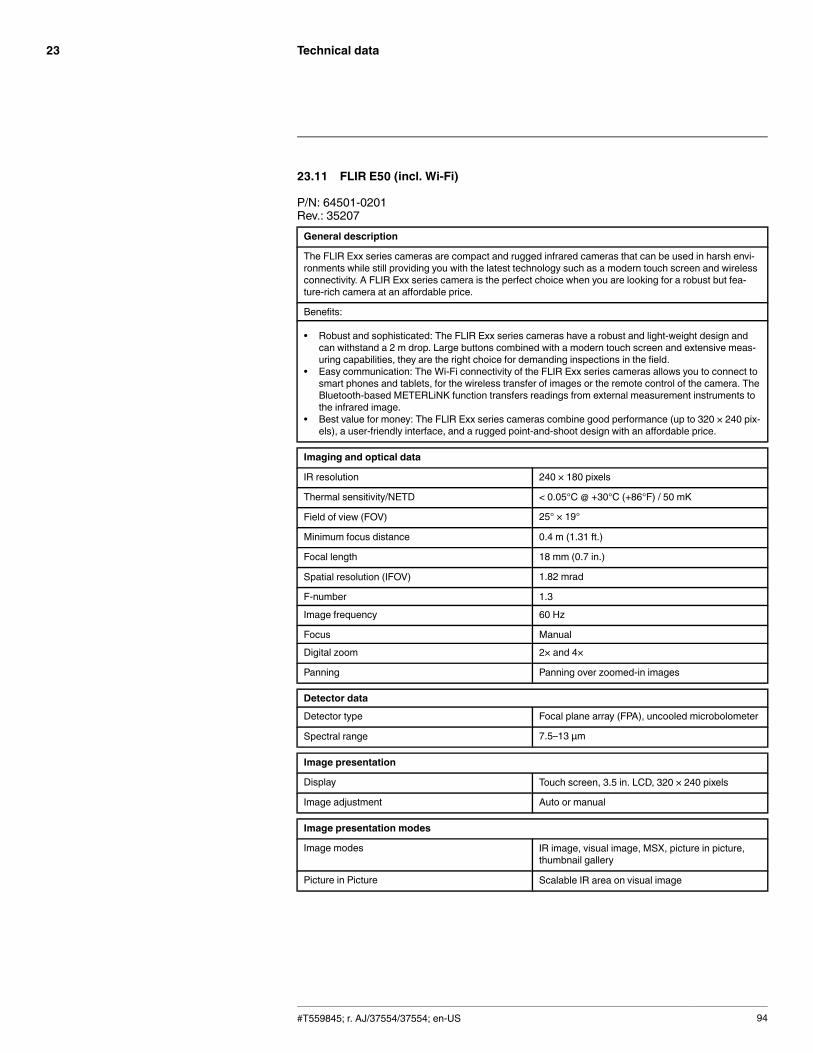
Technical data23
23.11 FLIR E50 (incl. Wi-Fi)
P/N: 64501-0201Rev.: 35207General description
The FLIR Exx series cameras are compact and rugged infrared cameras that can be used in harsh envi-ronments while still providing you with the latest technology such as a modern touch screen and wirelessconnectivity. A FLIR Exx series camera is the perfect choice when you are looking for a robust but fea-ture-rich camera at an affordable price.
Benefits:
• Robust and sophisticated: The FLIR Exx series cameras have a robust and light-weight design andcan withstand a 2 m drop. Large buttons combined with a modern touch screen and extensive meas-uring capabilities, they are the right choice for demanding inspections in the field.
• Easy communication: The Wi-Fi connectivity of the FLIR Exx series cameras allows you to connect tosmart phones and tablets, for the wireless transfer of images or the remote control of the camera. TheBluetooth-based METERLiNK function transfers readings from external measurement instruments tothe infrared image.
• Best value for money: The FLIR Exx series cameras combine good performance (up to 320 × 240 pix-els), a user-friendly interface, and a rugged point-and-shoot design with an affordable price.
Imaging and optical data
IR resolution 240 × 180 pixels
Thermal sensitivity/NETD < 0.05°C @ +30°C (+86°F) / 50 mK
Field of view (FOV) 25° × 19°
Minimum focus distance 0.4 m (1.31 ft.)
Focal length 18 mm (0.7 in.)
Spatial resolution (IFOV) 1.82 mrad
F-number 1.3
Image frequency 60 Hz
Focus Manual
Digital zoom 2× and 4×
Panning Panning over zoomed-in images
Detector data
Detector type Focal plane array (FPA), uncooled microbolometer
Spectral range 7.5–13 µm
Image presentation
Display Touch screen, 3.5 in. LCD, 320 × 240 pixels
Image adjustment Auto or manual
Image presentation modes
Image modes IR image, visual image, MSX, picture in picture,thumbnail gallery
Picture in Picture Scalable IR area on visual image
#T559845; r. AJ/37554/37554; en-US 94

Technical data23
Measurement
Object temperature range • –20°C to +120°C (–4°F to +248°F)• 0°C to +650°C (+32°F to +1202°F)
Accuracy ±2°C (±3.6°F) or ±2% of reading, for ambient tem-perature 10°C to 35°C (+50°F to 95°F)
Measurement analysis
Spotmeter 3
Area 3 boxes with max./min./average
Automatic hot/cold detection Auto hot or cold spotmeter markers within area
Difference temperature Delta temperature between measurement func-tions or reference temperature
Reference temperature Manually set or captured from any measurementfunction
Emissivity correction Variable from 0.01 to 1.0 or selected from materialslist
External optics/windows correction Automatic, based on inputs of optics/window trans-mission and temperature
Measurement corrections Reflected temperature, optics transmission and at-mospheric transmission
Set-up
Color palettes Arctic, Gray, Iron, Lava, Rainbow and Rainbow HC
Set-up commands Local adaptation of units, language, date and timeformats
Storage of images
Image storage Standard JPEG, including measurement data, onmemory card
Image storage mode Simultaneous storage of images in IR, visual andMSX
Image annotations
Voice 60 seconds (via Bluetooth)
Text Text from predefined list or soft keyboard on touchscreen
METERLiNK Wireless connection (Bluetooth) to:
FLIR meters with METERLiNK
Report generation • FLIR Tools software specifically designed toprovide an easy way to create inspection re-ports. It is available on the major platforms –Android, Windows, MacOS, and iOS.
Video recording in camera
Non-radiometric IR video recording MPEG-4 to memory card
Video streaming
Radiometric IR video streaming Full dynamic to PC using USB
Non-radiometric IR video streaming Uncompressed colorized video using USB
#T559845; r. AJ/37554/37554; en-US 95
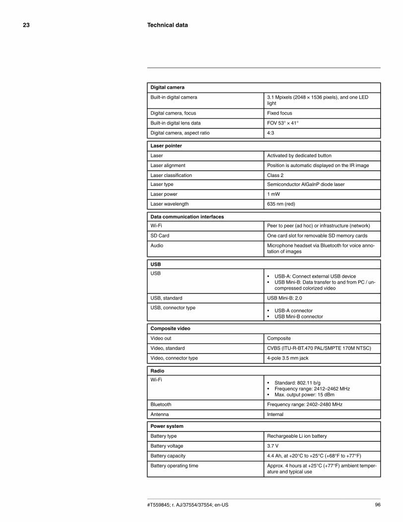
Technical data23
Digital camera
Built-in digital camera 3.1 Mpixels (2048 × 1536 pixels), and one LEDlight
Digital camera, focus Fixed focus
Built-in digital lens data FOV 53° × 41°
Digital camera, aspect ratio 4:3
Laser pointer
Laser Activated by dedicated button
Laser alignment Position is automatic displayed on the IR image
Laser classification Class 2
Laser type Semiconductor AlGaInP diode laser
Laser power 1 mW
Laser wavelength 635 nm (red)
Data communication interfaces
Wi-Fi Peer to peer (ad hoc) or infrastructure (network)
SD Card One card slot for removable SD memory cards
Audio Microphone headset via Bluetooth for voice anno-tation of images
USB
USB • USB-A: Connect external USB device• USB Mini-B: Data transfer to and from PC / un-
compressed colorized video
USB, standard USB Mini-B: 2.0
USB, connector type • USB-A connector• USB Mini-B connector
Composite video
Video out Composite
Video, standard CVBS (ITU-R-BT.470 PAL/SMPTE 170M NTSC)
Video, connector type 4-pole 3.5 mm jack
Radio
Wi-Fi • Standard: 802.11 b/g• Frequency range: 2412–2462 MHz• Max. output power: 15 dBm
Bluetooth Frequency range: 2402–2480 MHz
Antenna Internal
Power system
Battery type Rechargeable Li ion battery
Battery voltage 3.7 V
Battery capacity 4.4 Ah, at +20°C to +25°C (+68°F to +77°F)
Battery operating time Approx. 4 hours at +25°C (+77°F) ambient temper-ature and typical use
#T559845; r. AJ/37554/37554; en-US 96

Technical data23
Power system
Charging system In camera (AC adapter or 12 V from a vehicle) or 2-bay charger
Charging time 4 h to 90% capacity, charging status indicated byLED's
Charging temperature 0°C to +45°C (+32°F to +113°F)
Power management Automatic shutdown and sleep mode (userselectable)
AC operation AC adapter, 90–260 VAC input, 12 V output tocamera
Start-up time from sleep mode Instant on
Environmental data
Operating temperature range –15°C to +50°C (+5°F to +122°F)
Storage temperature range –40°C to +70°C (–40°F to +158°F)
Humidity (operating and storage) IEC 60068-2-30/24 h 95% relative humidity +25°Cto +40°C (+77°F to +104°F) / 2 cycles
EMC • ETSI EN 301 489-1 (radio)• ETSI EN 301 489-17• EN 61000-6-2 (Immunity)• EN 61000-6-3 (Emission)• FCC 47 CFR Part 15 B (Emission)• ICES-003
Radio spectrum • ETSI EN 300 328• FCC Part 15.247• RSS-210
Magnetic fields EN 61 000-4-8, Test level 5 for continuous field (se-vere industrial environment)
Encapsulation IP 54 (IEC 60529)
Shock 25 g (IEC 60068-2-27)
Vibration 2 g (IEC 60068-2-6)
Drop 2 m (6.6 ft.)
Safety EN/UL/CSA/PSE 60950-1
Physical data
Camera weight, incl. battery 0.869 kg (1.91 lb.)
Camera size (L × W × H) 246 × 97 × 184 mm (9.7 × 3.8 × 7.2 in.)
Tripod mounting UNC ¼"-20 (adapter needed)
Material • Polycarbonate + acrylonitrile butadiene styrene(PC-ABS)
• Thixomold magnesium• Thermoplastic elastomer (TPE)
Color Graphite gray and black
#T559845; r. AJ/37554/37554; en-US 97

Technical data23
Shipping information
Packaging, type Cardboard box
List of contents • Hard transport case• Infrared camera with lens• Battery• Handstrap• Memory card• Power supply, incl. multi-plugs• Printed documentation• USB cable• Video cable
Packaging, weight 5.2 kg (11.5 lb.)
Packaging, size 500 × 190 × 370 mm (19.7 × 7.5 × 14.6 in.)
EAN-13 4743254001145
UPC-12 845188005177
Country of origin Estonia
Supplies & accessories:
• 1196961; IR lens, f = 30 mm, 15° incl. case• 1196960; IR lens, f = 10 mm, 45° incl. case• T910814; Power supply, incl. multi plugs• T911230ACC; Memory card SDHC 4 GB• 1910423; USB cable Std A <-> Mini-B• T198509; Cigarette lighter adapter kit, 12 VDC, 1.2 m/3.9 ft.• 1910582ACC; Video cable• T197771ACC; Bluetooth Headset• T911093; Tool belt• T198125; Battery charger, incl. power supply with multi plugs (Exx, Kxx)• T199235; High-temperature lens• T198113; IR lens, 76 mm (6°) with case and mounting support for Exx• T198487; Li-Ion Battery pack 3.7V 17Wh• T198484; Pouch for FLIR Exx series• T198485; Sun shield• T198341ACC; Transport case Exx• T198486; Tripod Adapter• T199363ACC; Battery Li-ion 3.6 V, 5.2 Ah, 19 Wh• 19250-100; IR Window 2 in• 19251-100; IR Window 3 in.• 19252-100; IR Window 4 in.• 19250-200; SS IR Window 2 in.• 19251-200; SS IR Window 3 in.• 19252-200; SS IR Window 4 in.• T198586; FLIR Reporter Professional (license only)• T198584; FLIR Tools• T198583; FLIR Tools+ (download card incl. license key)• DSW-10000; FLIR IR Camera Player• APP-10002; FLIR Tools Mobile (Android Application)• APP-10004; FLIR Tools (MacOS Application)• T198697; FLIR ResearchIR Max + HSDR 4 (hardware sec. dev.)• T199014; FLIR ResearchIR Max + HSDR 4 (printed license key)• T199044; FLIR ResearchIR Max + HSDR 4 Upgrade (printed license key)• T198696; FLIR ResearchIR Max 4 (hardware sec. dev.)• T199013; FLIR ResearchIR Max 4 (printed license key)
#T559845; r. AJ/37554/37554; en-US 98
Technical data23
• T199043; FLIR ResearchIR Max 4 Upgrade (printed license key)• T198731; FLIR ResearchIR Standard 4 (hardware sec. dev.)• T199012; FLIR ResearchIR Standard 4 (printed license key)• T199042; FLIR ResearchIR Standard 4 Upgrade (printed license key)• T199233; FLIR Atlas SDK for .NET• T199234; FLIR Atlas SDK for MATLAB
#T559845; r. AJ/37554/37554; en-US 99
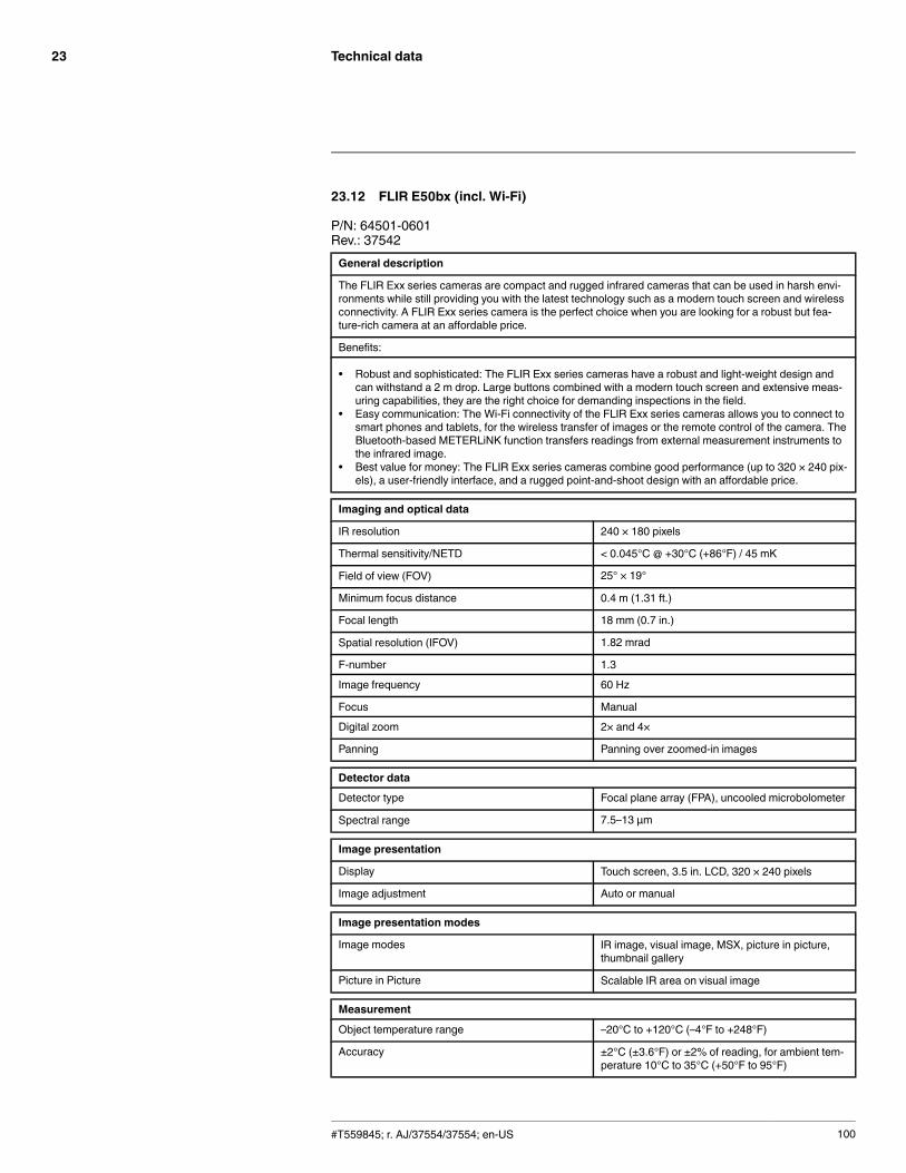
Technical data23
23.12 FLIR E50bx (incl. Wi-Fi)
P/N: 64501-0601Rev.: 37542General description
The FLIR Exx series cameras are compact and rugged infrared cameras that can be used in harsh envi-ronments while still providing you with the latest technology such as a modern touch screen and wirelessconnectivity. A FLIR Exx series camera is the perfect choice when you are looking for a robust but fea-ture-rich camera at an affordable price.
Benefits:
• Robust and sophisticated: The FLIR Exx series cameras have a robust and light-weight design andcan withstand a 2 m drop. Large buttons combined with a modern touch screen and extensive meas-uring capabilities, they are the right choice for demanding inspections in the field.
• Easy communication: The Wi-Fi connectivity of the FLIR Exx series cameras allows you to connect tosmart phones and tablets, for the wireless transfer of images or the remote control of the camera. TheBluetooth-based METERLiNK function transfers readings from external measurement instruments tothe infrared image.
• Best value for money: The FLIR Exx series cameras combine good performance (up to 320 × 240 pix-els), a user-friendly interface, and a rugged point-and-shoot design with an affordable price.
Imaging and optical data
IR resolution 240 × 180 pixels
Thermal sensitivity/NETD < 0.045°C @ +30°C (+86°F) / 45 mK
Field of view (FOV) 25° × 19°
Minimum focus distance 0.4 m (1.31 ft.)
Focal length 18 mm (0.7 in.)
Spatial resolution (IFOV) 1.82 mrad
F-number 1.3
Image frequency 60 Hz
Focus Manual
Digital zoom 2× and 4×
Panning Panning over zoomed-in images
Detector data
Detector type Focal plane array (FPA), uncooled microbolometer
Spectral range 7.5–13 µm
Image presentation
Display Touch screen, 3.5 in. LCD, 320 × 240 pixels
Image adjustment Auto or manual
Image presentation modes
Image modes IR image, visual image, MSX, picture in picture,thumbnail gallery
Picture in Picture Scalable IR area on visual image
Measurement
Object temperature range –20°C to +120°C (–4°F to +248°F)
Accuracy ±2°C (±3.6°F) or ±2% of reading, for ambient tem-perature 10°C to 35°C (+50°F to 95°F)
#T559845; r. AJ/37554/37554; en-US 100
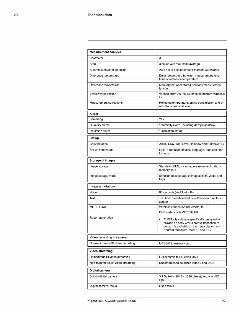
Technical data23
Measurement analysis
Spotmeter 3
Area 3 boxes with max./min./average
Automatic hot/cold detection Auto hot or cold spotmeter markers within area
Difference temperature Delta temperature between measurement func-tions or reference temperature
Reference temperature Manually set or captured from any measurementfunction
Emissivity correction Variable from 0.01 to 1.0 or selected from materialslist
Measurement corrections Reflected temperature, optics transmission and at-mospheric transmission
Alarm
Screening Yes
Humidity alarm 1 humidity alarm, including dew point alarm
Insulation alarm 1 insulation alarm
Set-up
Color palettes Arctic, Gray, Iron, Lava, Rainbow and Rainbow HC
Set-up commands Local adaptation of units, language, date and timeformats
Storage of images
Image storage Standard JPEG, including measurement data, onmemory card
Image storage mode Simultaneous storage of images in IR, visual andMSX
Image annotations
Voice 60 seconds (via Bluetooth)
Text Text from predefined list or soft keyboard on touchscreen
METERLiNK Wireless connection (Bluetooth) to:
FLIR meters with METERLiNK
Report generation • FLIR Tools software specifically designed toprovide an easy way to create inspection re-ports. It is available on the major platforms –Android, Windows, MacOS, and iOS.
Video recording in camera
Non-radiometric IR video recording MPEG-4 to memory card
Video streaming
Radiometric IR video streaming Full dynamic to PC using USB
Non-radiometric IR video streaming Uncompressed colorized video using USB
Digital camera
Built-in digital camera 3.1 Mpixels (2048 × 1536 pixels), and one LEDlight
Digital camera, focus Fixed focus
#T559845; r. AJ/37554/37554; en-US 101
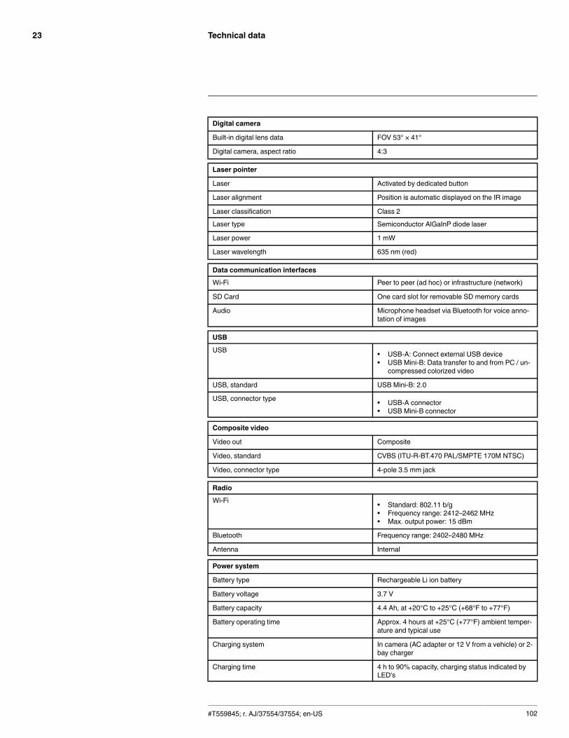
Technical data23
Digital camera
Built-in digital lens data FOV 53° × 41°
Digital camera, aspect ratio 4:3
Laser pointer
Laser Activated by dedicated button
Laser alignment Position is automatic displayed on the IR image
Laser classification Class 2
Laser type Semiconductor AlGaInP diode laser
Laser power 1 mW
Laser wavelength 635 nm (red)
Data communication interfaces
Wi-Fi Peer to peer (ad hoc) or infrastructure (network)
SD Card One card slot for removable SD memory cards
Audio Microphone headset via Bluetooth for voice anno-tation of images
USB
USB • USB-A: Connect external USB device• USB Mini-B: Data transfer to and from PC / un-
compressed colorized video
USB, standard USB Mini-B: 2.0
USB, connector type • USB-A connector• USB Mini-B connector
Composite video
Video out Composite
Video, standard CVBS (ITU-R-BT.470 PAL/SMPTE 170M NTSC)
Video, connector type 4-pole 3.5 mm jack
Radio
Wi-Fi • Standard: 802.11 b/g• Frequency range: 2412–2462 MHz• Max. output power: 15 dBm
Bluetooth Frequency range: 2402–2480 MHz
Antenna Internal
Power system
Battery type Rechargeable Li ion battery
Battery voltage 3.7 V
Battery capacity 4.4 Ah, at +20°C to +25°C (+68°F to +77°F)
Battery operating time Approx. 4 hours at +25°C (+77°F) ambient temper-ature and typical use
Charging system In camera (AC adapter or 12 V from a vehicle) or 2-bay charger
Charging time 4 h to 90% capacity, charging status indicated byLED's
#T559845; r. AJ/37554/37554; en-US 102

Technical data23
Power system
Charging temperature 0°C to +45°C (+32°F to +113°F)
Power management Automatic shutdown and sleep mode (userselectable)
AC operation AC adapter, 90–260 VAC input, 12 V output tocamera
Start-up time from sleep mode Instant on
Environmental data
Operating temperature range –15°C to +50°C (+5°F to +122°F)
Storage temperature range –40°C to +70°C (–40°F to +158°F)
Humidity (operating and storage) IEC 60068-2-30/24 h 95% relative humidity +25°Cto +40°C (+77°F to +104°F) / 2 cycles
EMC • ETSI EN 301 489-1 (radio)• ETSI EN 301 489-17• EN 61000-6-2 (Immunity)• EN 61000-6-3 (Emission)• FCC 47 CFR Part 15 B (Emission)• ICES-003
Radio spectrum • ETSI EN 300 328• FCC Part 15.247• RSS-210
Magnetic fields EN 61 000-4-8, Test level 5 for continuous field (se-vere industrial environment)
Encapsulation IP 54 (IEC 60529)
Shock 25 g (IEC 60068-2-27)
Vibration 2 g (IEC 60068-2-6)
Drop 2 m (6.6 ft.)
Safety EN/UL/CSA/PSE 60950-1
Physical data
Camera weight, incl. battery 0.869 kg (1.91 lb.)
Camera size (L × W × H) 246 × 97 × 184 mm (9.7 × 3.8 × 7.2 in.)
Tripod mounting UNC ¼"-20 (adapter needed)
Material • Polycarbonate + acrylonitrile butadiene styrene(PC-ABS)
• Thixomold magnesium• Thermoplastic elastomer (TPE)
Color Graphite gray and black
#T559845; r. AJ/37554/37554; en-US 103

Technical data23
Shipping information
Packaging, type Cardboard box
List of contents • Hard transport case• Infrared camera with lens• Battery• Handstrap• Memory card• Power supply, incl. multi-plugs• Printed documentation• USB cable• Video cable
Packaging, weight 5.2 kg (11.5 lb.)
Packaging, size 500 × 190 × 370 mm (19.7 × 7.5 × 14.6 in.)
EAN-13 4743254001183
UPC-12 845188005214
Country of origin Estonia
Supplies & accessories:
• 1196961; IR lens, f = 30 mm, 15° incl. case• 1196960; IR lens, f = 10 mm, 45° incl. case• T910814; Power supply, incl. multi plugs• T911230ACC; Memory card SDHC 4 GB• 1910423; USB cable Std A <-> Mini-B• T198509; Cigarette lighter adapter kit, 12 VDC, 1.2 m/3.9 ft.• 1910582ACC; Video cable• T197771ACC; Bluetooth Headset• T911093; Tool belt• T198125; Battery charger, incl. power supply with multi plugs (Exx, Kxx)• T199235; High-temperature lens• T198113; IR lens, 76 mm (6°) with case and mounting support for Exx• T198487; Li-Ion Battery pack 3.7V 17Wh• T198484; Pouch for FLIR Exx series• T198485; Sun shield• T198341ACC; Transport case Exx• T198486; Tripod Adapter• T199363ACC; Battery Li-ion 3.6 V, 5.2 Ah, 19 Wh• 19250-100; IR Window 2 in• 19251-100; IR Window 3 in.• 19252-100; IR Window 4 in.• 19250-200; SS IR Window 2 in.• 19251-200; SS IR Window 3 in.• 19252-200; SS IR Window 4 in.• T198586; FLIR Reporter Professional (license only)• T198584; FLIR Tools• T198583; FLIR Tools+ (download card incl. license key)• DSW-10000; FLIR IR Camera Player• APP-10002; FLIR Tools Mobile (Android Application)• APP-10004; FLIR Tools (MacOS Application)• T198697; FLIR ResearchIR Max + HSDR 4 (hardware sec. dev.)• T199014; FLIR ResearchIR Max + HSDR 4 (printed license key)• T199044; FLIR ResearchIR Max + HSDR 4 Upgrade (printed license key)• T198696; FLIR ResearchIR Max 4 (hardware sec. dev.)• T199013; FLIR ResearchIR Max 4 (printed license key)
#T559845; r. AJ/37554/37554; en-US 104

Technical data23
• T199043; FLIR ResearchIR Max 4 Upgrade (printed license key)• T198731; FLIR ResearchIR Standard 4 (hardware sec. dev.)• T199012; FLIR ResearchIR Standard 4 (printed license key)• T199042; FLIR ResearchIR Standard 4 Upgrade (printed license key)• T199233; FLIR Atlas SDK for .NET• T199234; FLIR Atlas SDK for MATLAB
#T559845; r. AJ/37554/37554; en-US 105

Technical data23
23.13 FLIR E60
P/N: 64502-1202Rev.: 35207General description
The FLIR Exx series cameras are compact and rugged infrared cameras that can be used in harsh envi-ronments while still providing you with the latest technology such as a modern touch screen. A FLIR Exxseries camera is the perfect choice when you are looking for a robust but feature-rich camera at an afford-able price.
Benefits:
• Robust and sophisticated: The FLIR Exx series cameras have a robust and light-weight design andcan withstand a 2 m drop. Large buttons combined with a modern touch screen and extensive meas-uring capabilities, they are the right choice for demanding inspections in the field.
• Best value for money: The FLIR Exx series cameras combine good performance (up to 320 × 240 pix-els), a user-friendly interface, and a rugged point-and-shoot design with an affordable price.
Imaging and optical data
IR resolution 320 × 240 pixels
Thermal sensitivity/NETD < 0.05°C @ +30°C (+86°F) / 50 mK
Field of view (FOV) 25° × 19°
Minimum focus distance 0.4 m (1.31 ft.)
Focal length 18 mm (0.7 in.)
Spatial resolution (IFOV) 1.36 mrad
F-number 1.3
Image frequency 60 Hz
Focus Manual
Digital zoom 2× and 4×
Panning Panning over zoomed-in images
Detector data
Detector type Focal plane array (FPA), uncooled microbolometer
Spectral range 7.5–13 µm
Image presentation
Display Touch screen, 3.5 in. LCD, 320 × 240 pixels
Image adjustment Auto or manual
Image presentation modes
Image modes IR image, visual image, MSX, picture in picture,thumbnail gallery
Picture in Picture Scalable IR area on visual image
Measurement
Object temperature range • –20°C to +120°C (–4°F to +248°F)• 0°C to +650°C (+32°F to +1202°F)
Accuracy ±2°C (±3.6°F) or ±2% of reading, for ambient tem-perature 10°C to 35°C (+50°F to 95°F)
#T559845; r. AJ/37554/37554; en-US 106

Technical data23
Measurement analysis
Spotmeter 3
Area 3 boxes with max./min./average
Automatic hot/cold detection Auto hot or cold spotmeter markers within area
Difference temperature Delta temperature between measurement func-tions or reference temperature
Reference temperature Manually set or captured from any measurementfunction
Emissivity correction Variable from 0.01 to 1.0 or selected from materialslist
External optics/windows correction Automatic, based on inputs of optics/window trans-mission and temperature
Measurement corrections Reflected temperature, optics transmission and at-mospheric transmission
Set-up
Color palettes Arctic, Gray, Iron, Lava, Rainbow and Rainbow HC
Set-up commands Local adaptation of units, language, date and timeformats
Storage of images
Image storage Standard JPEG, including measurement data, onmemory card
Image storage mode Simultaneous storage of images in IR, visual andMSX
Image annotations
Text Text from predefined list or soft keyboard on touchscreen
Report generation • FLIR Tools software specifically designed toprovide an easy way to create inspection re-ports. It is available on the major platforms –Android, Windows, MacOS, and iOS.
Video recording in camera
Non-radiometric IR video recording MPEG-4 to memory card
Video streaming
Radiometric IR video streaming Full dynamic to PC using USB
Non-radiometric IR video streaming Uncompressed colorized video using USB
Digital camera
Built-in digital camera 3.1 Mpixels (2048 × 1536 pixels), and one LEDlight
Digital camera, focus Fixed focus
Built-in digital lens data FOV 53° × 41°
Digital camera, aspect ratio 4:3
Laser pointer
Laser Activated by dedicated button
Laser alignment Position is automatic displayed on the IR image
#T559845; r. AJ/37554/37554; en-US 107

Technical data23
Laser pointer
Laser classification Class 2
Laser type Semiconductor AlGaInP diode laser
Laser power 1 mW
Laser wavelength 635 nm (red)
Data communication interfaces
SD Card One card slot for removable SD memory cards
USB
USB • USB-A: Connect external USB device• USB Mini-B: Data transfer to and from PC / un-
compressed colorized video
USB, standard USB Mini-B: 2.0
USB, connector type • USB-A connector• USB Mini-B connector
Composite video
Video out Composite
Video, standard CVBS (ITU-R-BT.470 PAL/SMPTE 170M NTSC)
Video, connector type 4-pole 3.5 mm jack
Power system
Battery type Rechargeable Li ion battery
Battery voltage 3.7 V
Battery capacity 4.4 Ah, at +20°C to +25°C (+68°F to +77°F)
Battery operating time Approx. 4 hours at +25°C (+77°F) ambient temper-ature and typical use
Charging system In camera (AC adapter or 12 V from a vehicle) or 2-bay charger
Charging time 4 h to 90% capacity, charging status indicated byLED's
Charging temperature 0°C to +45°C (+32°F to +113°F)
Power management Automatic shutdown and sleep mode (userselectable)
AC operation AC adapter, 90–260 VAC input, 12 V output tocamera
Start-up time from sleep mode Instant on
Environmental data
Operating temperature range –15°C to +50°C (+5°F to +122°F)
Storage temperature range –40°C to +70°C (–40°F to +158°F)
Humidity (operating and storage) IEC 60068-2-30/24 h 95% relative humidity +25°Cto +40°C (+77°F to +104°F) / 2 cycles
EMC • EN 61000-6-2 (Immunity)• EN 61000-6-3 (Emission)• FCC 47 CFR Part 15 B (Emission)
#T559845; r. AJ/37554/37554; en-US 108
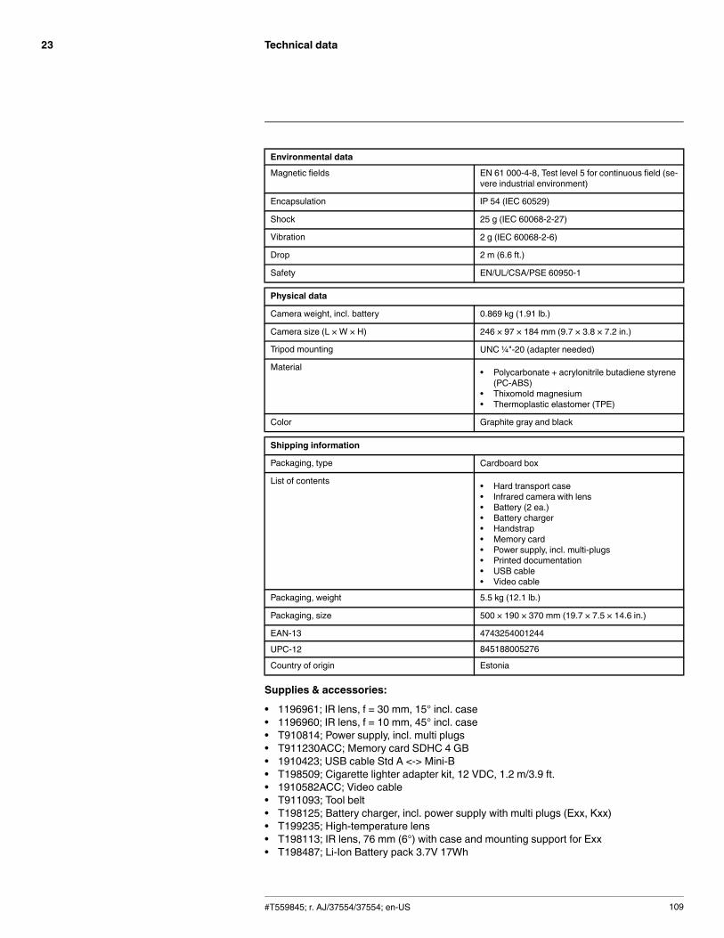
Technical data23
Environmental data
Magnetic fields EN 61 000-4-8, Test level 5 for continuous field (se-vere industrial environment)
Encapsulation IP 54 (IEC 60529)
Shock 25 g (IEC 60068-2-27)
Vibration 2 g (IEC 60068-2-6)
Drop 2 m (6.6 ft.)
Safety EN/UL/CSA/PSE 60950-1
Physical data
Camera weight, incl. battery 0.869 kg (1.91 lb.)
Camera size (L × W × H) 246 × 97 × 184 mm (9.7 × 3.8 × 7.2 in.)
Tripod mounting UNC ¼"-20 (adapter needed)
Material • Polycarbonate + acrylonitrile butadiene styrene(PC-ABS)
• Thixomold magnesium• Thermoplastic elastomer (TPE)
Color Graphite gray and black
Shipping information
Packaging, type Cardboard box
List of contents • Hard transport case• Infrared camera with lens• Battery (2 ea.)• Battery charger• Handstrap• Memory card• Power supply, incl. multi-plugs• Printed documentation• USB cable• Video cable
Packaging, weight 5.5 kg (12.1 lb.)
Packaging, size 500 × 190 × 370 mm (19.7 × 7.5 × 14.6 in.)
EAN-13 4743254001244
UPC-12 845188005276
Country of origin Estonia
Supplies & accessories:
• 1196961; IR lens, f = 30 mm, 15° incl. case• 1196960; IR lens, f = 10 mm, 45° incl. case• T910814; Power supply, incl. multi plugs• T911230ACC; Memory card SDHC 4 GB• 1910423; USB cable Std A <-> Mini-B• T198509; Cigarette lighter adapter kit, 12 VDC, 1.2 m/3.9 ft.• 1910582ACC; Video cable• T911093; Tool belt• T198125; Battery charger, incl. power supply with multi plugs (Exx, Kxx)• T199235; High-temperature lens• T198113; IR lens, 76 mm (6°) with case and mounting support for Exx• T198487; Li-Ion Battery pack 3.7V 17Wh
#T559845; r. AJ/37554/37554; en-US 109
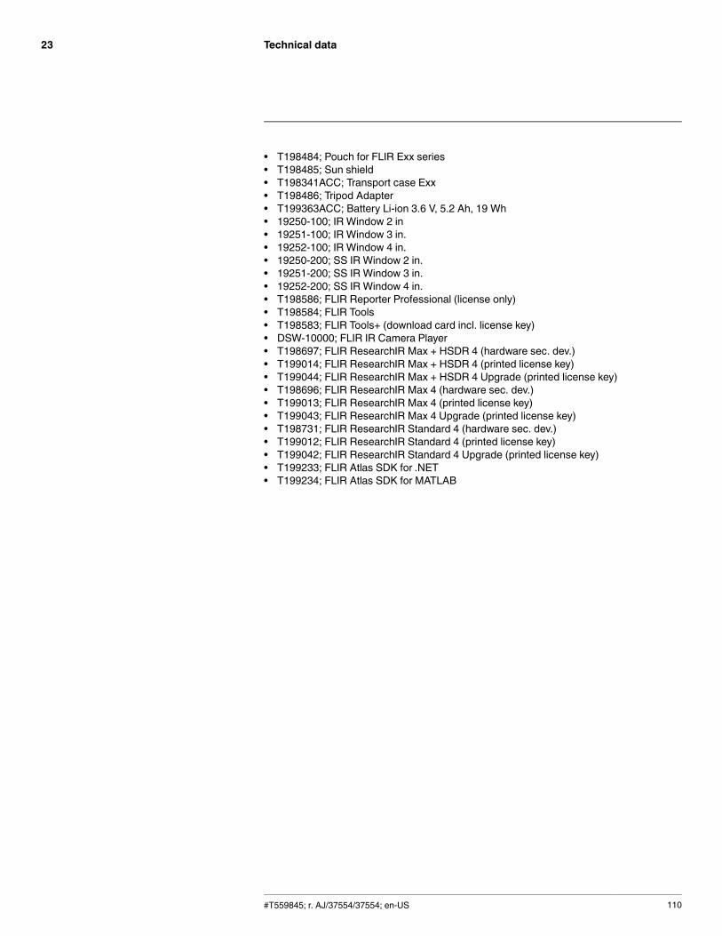
Technical data23
• T198484; Pouch for FLIR Exx series• T198485; Sun shield• T198341ACC; Transport case Exx• T198486; Tripod Adapter• T199363ACC; Battery Li-ion 3.6 V, 5.2 Ah, 19 Wh• 19250-100; IR Window 2 in• 19251-100; IR Window 3 in.• 19252-100; IR Window 4 in.• 19250-200; SS IR Window 2 in.• 19251-200; SS IR Window 3 in.• 19252-200; SS IR Window 4 in.• T198586; FLIR Reporter Professional (license only)• T198584; FLIR Tools• T198583; FLIR Tools+ (download card incl. license key)• DSW-10000; FLIR IR Camera Player• T198697; FLIR ResearchIR Max + HSDR 4 (hardware sec. dev.)• T199014; FLIR ResearchIR Max + HSDR 4 (printed license key)• T199044; FLIR ResearchIR Max + HSDR 4 Upgrade (printed license key)• T198696; FLIR ResearchIR Max 4 (hardware sec. dev.)• T199013; FLIR ResearchIR Max 4 (printed license key)• T199043; FLIR ResearchIR Max 4 Upgrade (printed license key)• T198731; FLIR ResearchIR Standard 4 (hardware sec. dev.)• T199012; FLIR ResearchIR Standard 4 (printed license key)• T199042; FLIR ResearchIR Standard 4 Upgrade (printed license key)• T199233; FLIR Atlas SDK for .NET• T199234; FLIR Atlas SDK for MATLAB
#T559845; r. AJ/37554/37554; en-US 110

Technical data23
23.14 FLIR E60 (incl. Wi-Fi)
P/N: 64501-0302Rev.: 35207General description
The FLIR Exx series cameras are compact and rugged infrared cameras that can be used in harsh envi-ronments while still providing you with the latest technology such as a modern touch screen and wirelessconnectivity. A FLIR Exx series camera is the perfect choice when you are looking for a robust but fea-ture-rich camera at an affordable price.
Benefits:
• Robust and sophisticated: The FLIR Exx series cameras have a robust and light-weight design andcan withstand a 2 m drop. Large buttons combined with a modern touch screen and extensive meas-uring capabilities, they are the right choice for demanding inspections in the field.
• Easy communication: The Wi-Fi connectivity of the FLIR Exx series cameras allows you to connect tosmart phones and tablets, for the wireless transfer of images or the remote control of the camera. TheBluetooth-based METERLiNK function transfers readings from external measurement instruments tothe infrared image.
• Best value for money: The FLIR Exx series cameras combine good performance (up to 320 × 240 pix-els), a user-friendly interface, and a rugged point-and-shoot design with an affordable price.
Imaging and optical data
IR resolution 320 × 240 pixels
Thermal sensitivity/NETD < 0.05°C @ +30°C (+86°F) / 50 mK
Field of view (FOV) 25° × 19°
Minimum focus distance 0.4 m (1.31 ft.)
Focal length 18 mm (0.7 in.)
Spatial resolution (IFOV) 1.36 mrad
F-number 1.3
Image frequency 60 Hz
Focus Manual
Digital zoom 2× and 4×
Panning Panning over zoomed-in images
Detector data
Detector type Focal plane array (FPA), uncooled microbolometer
Spectral range 7.5–13 µm
Image presentation
Display Touch screen, 3.5 in. LCD, 320 × 240 pixels
Image adjustment Auto or manual
Image presentation modes
Image modes IR image, visual image, MSX, picture in picture,thumbnail gallery
Picture in Picture Scalable IR area on visual image
#T559845; r. AJ/37554/37554; en-US 111

Technical data23
Measurement
Object temperature range • –20°C to +120°C (–4°F to +248°F)• 0°C to +650°C (+32°F to +1202°F)
Accuracy ±2°C (±3.6°F) or ±2% of reading, for ambient tem-perature 10°C to 35°C (+50°F to 95°F)
Measurement analysis
Spotmeter 3
Area 3 boxes with max./min./average
Automatic hot/cold detection Auto hot or cold spotmeter markers within area
Difference temperature Delta temperature between measurement func-tions or reference temperature
Reference temperature Manually set or captured from any measurementfunction
Emissivity correction Variable from 0.01 to 1.0 or selected from materialslist
External optics/windows correction Automatic, based on inputs of optics/window trans-mission and temperature
Measurement corrections Reflected temperature, optics transmission and at-mospheric transmission
Set-up
Color palettes Arctic, Gray, Iron, Lava, Rainbow and Rainbow HC
Set-up commands Local adaptation of units, language, date and timeformats
Storage of images
Image storage Standard JPEG, including measurement data, onmemory card
Image storage mode Simultaneous storage of images in IR, visual andMSX
Image annotations
Voice 60 seconds (via Bluetooth)
Text Text from predefined list or soft keyboard on touchscreen
METERLiNK Wireless connection (Bluetooth) to:
FLIR meters with METERLiNK
Report generation • FLIR Tools software specifically designed toprovide an easy way to create inspection re-ports. It is available on the major platforms –Android, Windows, MacOS, and iOS.
Video recording in camera
Non-radiometric IR video recording MPEG-4 to memory card
Video streaming
Radiometric IR video streaming Full dynamic to PC using USB
Non-radiometric IR video streaming Uncompressed colorized video using USB
#T559845; r. AJ/37554/37554; en-US 112

Technical data23
Digital camera
Built-in digital camera 3.1 Mpixels (2048 × 1536 pixels), and one LEDlight
Digital camera, focus Fixed focus
Built-in digital lens data FOV 53° × 41°
Digital camera, aspect ratio 4:3
Laser pointer
Laser Activated by dedicated button
Laser alignment Position is automatic displayed on the IR image
Laser classification Class 2
Laser type Semiconductor AlGaInP diode laser
Laser power 1 mW
Laser wavelength 635 nm (red)
Data communication interfaces
Wi-Fi Peer to peer (ad hoc) or infrastructure (network)
SD Card One card slot for removable SD memory cards
Audio Microphone headset via Bluetooth for voice anno-tation of images
USB
USB • USB-A: Connect external USB device• USB Mini-B: Data transfer to and from PC / un-
compressed colorized video
USB, standard USB Mini-B: 2.0
USB, connector type • USB-A connector• USB Mini-B connector
Composite video
Video out Composite
Video, standard CVBS (ITU-R-BT.470 PAL/SMPTE 170M NTSC)
Video, connector type 4-pole 3.5 mm jack
Radio
Wi-Fi • Standard: 802.11 b/g• Frequency range: 2412–2462 MHz• Max. output power: 15 dBm
Bluetooth Frequency range: 2402–2480 MHz
Antenna Internal
Power system
Battery type Rechargeable Li ion battery
Battery voltage 3.7 V
Battery capacity 4.4 Ah, at +20°C to +25°C (+68°F to +77°F)
Battery operating time Approx. 4 hours at +25°C (+77°F) ambient temper-ature and typical use
#T559845; r. AJ/37554/37554; en-US 113

Technical data23
Power system
Charging system In camera (AC adapter or 12 V from a vehicle) or 2-bay charger
Charging time 4 h to 90% capacity, charging status indicated byLED's
Charging temperature 0°C to +45°C (+32°F to +113°F)
Power management Automatic shutdown and sleep mode (userselectable)
AC operation AC adapter, 90–260 VAC input, 12 V output tocamera
Start-up time from sleep mode Instant on
Environmental data
Operating temperature range –15°C to +50°C (+5°F to +122°F)
Storage temperature range –40°C to +70°C (–40°F to +158°F)
Humidity (operating and storage) IEC 60068-2-30/24 h 95% relative humidity +25°Cto +40°C (+77°F to +104°F) / 2 cycles
EMC • ETSI EN 301 489-1 (radio)• ETSI EN 301 489-17• EN 61000-6-2 (Immunity)• EN 61000-6-3 (Emission)• FCC 47 CFR Part 15 B (Emission)• ICES-003
Radio spectrum • ETSI EN 300 328• FCC Part 15.247• RSS-210
Magnetic fields EN 61 000-4-8, Test level 5 for continuous field (se-vere industrial environment)
Encapsulation IP 54 (IEC 60529)
Shock 25 g (IEC 60068-2-27)
Vibration 2 g (IEC 60068-2-6)
Drop 2 m (6.6 ft.)
Safety EN/UL/CSA/PSE 60950-1
Physical data
Camera weight, incl. battery 0.869 kg (1.91 lb.)
Camera size (L × W × H) 246 × 97 × 184 mm (9.7 × 3.8 × 7.2 in.)
Tripod mounting UNC ¼"-20 (adapter needed)
Material • Polycarbonate + acrylonitrile butadiene styrene(PC-ABS)
• Thixomold magnesium• Thermoplastic elastomer (TPE)
Color Graphite gray and black
#T559845; r. AJ/37554/37554; en-US 114

Technical data23
Shipping information
Packaging, type Cardboard box
List of contents • Hard transport case• Infrared camera with lens• Battery (2 ea.)• Battery charger• Handstrap• Memory card• Power supply, incl. multi-plugs• Printed documentation• USB cable• Video cable
Packaging, weight 5.5 kg (12.1 lb.)
Packaging, size 500 × 190 × 370 mm (19.7 × 7.5 × 14.6 in.)
EAN-13 4743254001152
UPC-12 845188005184
Country of origin Estonia
Supplies & accessories:
• 1196961; IR lens, f = 30 mm, 15° incl. case• 1196960; IR lens, f = 10 mm, 45° incl. case• T910814; Power supply, incl. multi plugs• T911230ACC; Memory card SDHC 4 GB• 1910423; USB cable Std A <-> Mini-B• T198509; Cigarette lighter adapter kit, 12 VDC, 1.2 m/3.9 ft.• 1910582ACC; Video cable• T197771ACC; Bluetooth Headset• T911093; Tool belt• T198125; Battery charger, incl. power supply with multi plugs (Exx, Kxx)• T199235; High-temperature lens• T198113; IR lens, 76 mm (6°) with case and mounting support for Exx• T198487; Li-Ion Battery pack 3.7V 17Wh• T198484; Pouch for FLIR Exx series• T198485; Sun shield• T198341ACC; Transport case Exx• T198486; Tripod Adapter• T199363ACC; Battery Li-ion 3.6 V, 5.2 Ah, 19 Wh• 19250-100; IR Window 2 in• 19251-100; IR Window 3 in.• 19252-100; IR Window 4 in.• 19250-200; SS IR Window 2 in.• 19251-200; SS IR Window 3 in.• 19252-200; SS IR Window 4 in.• T198586; FLIR Reporter Professional (license only)• T198584; FLIR Tools• T198583; FLIR Tools+ (download card incl. license key)• DSW-10000; FLIR IR Camera Player• APP-10002; FLIR Tools Mobile (Android Application)• APP-10004; FLIR Tools (MacOS Application)• T198697; FLIR ResearchIR Max + HSDR 4 (hardware sec. dev.)• T199014; FLIR ResearchIR Max + HSDR 4 (printed license key)• T199044; FLIR ResearchIR Max + HSDR 4 Upgrade (printed license key)• T198696; FLIR ResearchIR Max 4 (hardware sec. dev.)• T199013; FLIR ResearchIR Max 4 (printed license key)
#T559845; r. AJ/37554/37554; en-US 115

Technical data23
• T199043; FLIR ResearchIR Max 4 Upgrade (printed license key)• T198731; FLIR ResearchIR Standard 4 (hardware sec. dev.)• T199012; FLIR ResearchIR Standard 4 (printed license key)• T199042; FLIR ResearchIR Standard 4 Upgrade (printed license key)• T199233; FLIR Atlas SDK for .NET• T199234; FLIR Atlas SDK for MATLAB
#T559845; r. AJ/37554/37554; en-US 116

Technical data23
23.15 FLIR E60 with Educational kit (DE)
P/N: 64501-0307Rev.: 30791General description
The kit consists of a FLIR E60, a DVD with educational movies, and guidebooks about applications forthermal imaging in building, industrial and R&D environments.
See FLIR E60 for specifications.
Shipping information
List of contents • FLIR E60• Educational DVD• Building guidebook• Industrial guidebook• R&D guidebook
EAN-13 4743254001602
UPC-12 845188008987
Country of origin Estonia
Supplies & accessories:
• N/A
#T559845; r. AJ/37554/37554; en-US 117

Technical data23
23.16 FLIR E60 with Educational kit (EN)
P/N: 64501-0304Rev.: 30792General description
The kit consists of a FLIR E60, a DVD with educational movies, and guidebooks about applications forthermal imaging in building, industrial and R&D environments.
See FLIR E60 for specifications.
Shipping information
List of contents • FLIR E60• Educational DVD• Building guidebook• Industrial guidebook• R&D guidebook
EAN-13 4743254001572
UPC-12 845188008956
Country of origin Estonia
Supplies & accessories:
• N/A
#T559845; r. AJ/37554/37554; en-US 118

Technical data23
23.17 FLIR E60 with Educational kit (ES)
P/N: 64501-0308Rev.: 30793General description
The kit consists of a FLIR E60, a DVD with educational movies, and guidebooks about applications forthermal imaging in building, industrial and R&D environments.
See FLIR E60 for specifications.
Shipping information
List of contents • FLIR E60• Educational DVD• Building guidebook• Industrial guidebook• R&D guidebook
EAN-13 4743254001619
UPC-12 845188008994
Country of origin Estonia
Supplies & accessories:
• N/A
#T559845; r. AJ/37554/37554; en-US 119

Technical data23
23.18 FLIR E60 with Educational kit (FR)
P/N: 64501-0306Rev.: 30794General description
The kit consists of a FLIR E60, a DVD with educational movies, and guidebooks about applications forthermal imaging in building, industrial and R&D environments.
See FLIR E60 for specifications.
Shipping information
List of contents • FLIR E60• Educational DVD• Building guidebook• Industrial guidebook• R&D guidebook
EAN-13 4743254001596
UPC-12 845188008970
Country of origin Estonia
Supplies & accessories:
• N/A
#T559845; r. AJ/37554/37554; en-US 120

Technical data23
23.19 FLIR E60 with Educational kit (IT)
P/N: 64501-0305Rev.: 30795General description
The kit consists of a FLIR E60, a DVD with educational movies, and guidebooks about applications forthermal imaging in building, industrial and R&D environments.
See FLIR E60 for specifications.
Shipping information
List of contents • FLIR E60• Educational DVD• Building guidebook• Industrial guidebook• R&D guidebook
EAN-13 4743254001589
UPC-12 845188008963
Country of origin Estonia
Supplies & accessories:
• N/A
#T559845; r. AJ/37554/37554; en-US 121
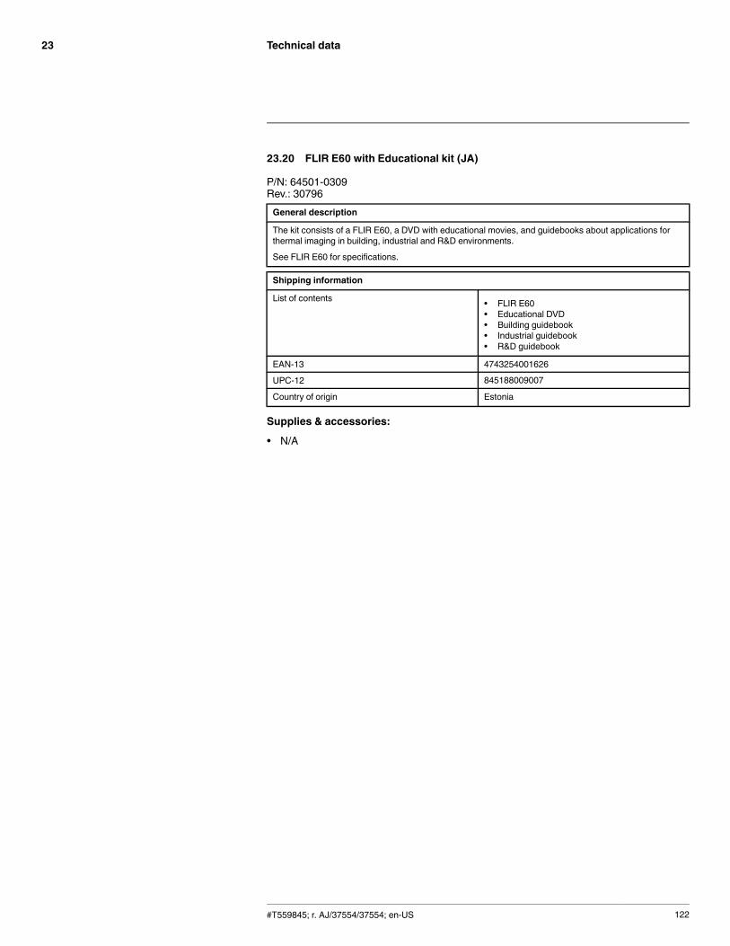
Technical data23
23.20 FLIR E60 with Educational kit (JA)
P/N: 64501-0309Rev.: 30796General description
The kit consists of a FLIR E60, a DVD with educational movies, and guidebooks about applications forthermal imaging in building, industrial and R&D environments.
See FLIR E60 for specifications.
Shipping information
List of contents • FLIR E60• Educational DVD• Building guidebook• Industrial guidebook• R&D guidebook
EAN-13 4743254001626
UPC-12 845188009007
Country of origin Estonia
Supplies & accessories:
• N/A
#T559845; r. AJ/37554/37554; en-US 122

Technical data23
23.21 FLIR E60 with Educational kit (KO)
P/N: 64501-0310Rev.: 30797General description
The kit consists of a FLIR E60, a DVD with educational movies, and guidebooks about applications forthermal imaging in building, industrial and R&D environments.
See FLIR E60 for specifications.
Shipping information
List of contents • FLIR E60• Educational DVD• Building guidebook• Industrial guidebook• R&D guidebook
EAN-13 4743254001633
UPC-12 845188009014
Country of origin Estonia
Supplies & accessories:
• N/A
#T559845; r. AJ/37554/37554; en-US 123

Technical data23
23.22 FLIR E60bx (incl. Wi-Fi)
P/N: 64501-0702Rev.: 37543General description
The FLIR Exx series cameras are compact and rugged infrared cameras that can be used in harsh envi-ronments while still providing you with the latest technology such as a modern touch screen and wirelessconnectivity. A FLIR Exx series camera is the perfect choice when you are looking for a robust but fea-ture-rich camera at an affordable price.
Benefits:
• Robust and sophisticated: The FLIR Exx series cameras have a robust and light-weight design andcan withstand a 2 m drop. Large buttons combined with a modern touch screen and extensive meas-uring capabilities, they are the right choice for demanding inspections in the field.
• Easy communication: The Wi-Fi connectivity of the FLIR Exx series cameras allows you to connect tosmart phones and tablets, for the wireless transfer of images or the remote control of the camera. TheBluetooth-based METERLiNK function transfers readings from external measurement instruments tothe infrared image.
• Best value for money: The FLIR Exx series cameras combine good performance (up to 320 × 240 pix-els), a user-friendly interface, and a rugged point-and-shoot design with an affordable price.
Imaging and optical data
IR resolution 320 × 240 pixels
Thermal sensitivity/NETD <0.045°C @ +30°C (+86°F) / 45 mK
Field of view (FOV) 25° × 19°
Minimum focus distance 0.4 m (1.31 ft.)
Focal length 18 mm (0.7 in.)
Spatial resolution (IFOV) 1.36 mrad
F-number 1.3
Image frequency 60 Hz
Focus Manual
Digital zoom 2× and 4×
Panning Panning over zoomed-in images
Detector data
Detector type Focal plane array (FPA), uncooled microbolometer
Spectral range 7.5–13 µm
Image presentation
Display Touch screen, 3.5 in. LCD, 320 × 240 pixels
Image adjustment Auto or manual
Image presentation modes
Image modes IR image, visual image, MSX, picture in picture,thumbnail gallery
Picture in Picture Scalable IR area on visual image
Measurement
Object temperature range –20°C to +120°C (–4°F to +248°F)
Accuracy ±2°C (±3.6°F) or ±2% of reading, for ambient tem-perature 10°C to 35°C (+50°F to 95°F)
#T559845; r. AJ/37554/37554; en-US 124

Technical data23
Measurement analysis
Spotmeter 3
Area 3 boxes with max./min./average
Automatic hot/cold detection Auto hot or cold spotmeter markers within area
Difference temperature Delta temperature between measurement func-tions or reference temperature
Reference temperature Manually set or captured from any measurementfunction
Emissivity correction Variable from 0.01 to 1.0 or selected from materialslist
Measurement corrections Reflected temperature, optics transmission and at-mospheric transmission
Alarm
Screening Yes
Humidity alarm 1 humidity alarm, including dew point alarm
Insulation alarm 1 insulation alarm
Set-up
Color palettes Arctic, Gray, Iron, Lava, Rainbow and Rainbow HC
Set-up commands Local adaptation of units, language, date and timeformats
Storage of images
Image storage Standard JPEG, including measurement data, onmemory card
Image storage mode Simultaneous storage of images in IR, visual andMSX
Image annotations
Voice 60 seconds (via Bluetooth)
Text Text from predefined list or soft keyboard on touchscreen
METERLiNK Wireless connection (Bluetooth) to:
FLIR meters with METERLiNK
Report generation • FLIR Tools software specifically designed toprovide an easy way to create inspection re-ports. It is available on the major platforms –Android, Windows, MacOS, and iOS.
Video recording in camera
Non-radiometric IR video recording MPEG-4 to memory card
Video streaming
Radiometric IR video streaming Full dynamic to PC using USB
Non-radiometric IR video streaming Uncompressed colorized video using USB
Digital camera
Built-in digital camera 3.1 Mpixels (2048 × 1536 pixels), and one LEDlight
Digital camera, focus Fixed focus
#T559845; r. AJ/37554/37554; en-US 125
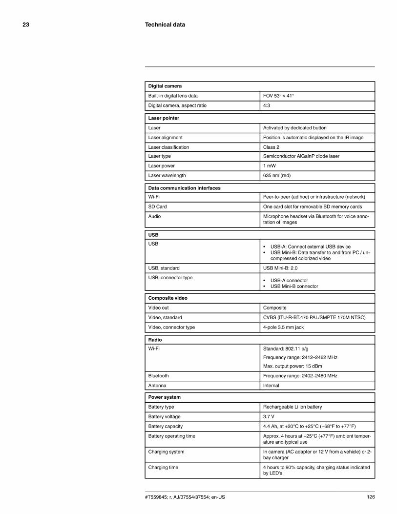
Technical data23
Digital camera
Built-in digital lens data FOV 53° × 41°
Digital camera, aspect ratio 4:3
Laser pointer
Laser Activated by dedicated button
Laser alignment Position is automatic displayed on the IR image
Laser classification Class 2
Laser type Semiconductor AlGaInP diode laser
Laser power 1 mW
Laser wavelength 635 nm (red)
Data communication interfaces
Wi-Fi Peer-to-peer (ad hoc) or infrastructure (network)
SD Card One card slot for removable SD memory cards
Audio Microphone headset via Bluetooth for voice anno-tation of images
USB
USB • USB-A: Connect external USB device• USB Mini-B: Data transfer to and from PC / un-
compressed colorized video
USB, standard USB Mini-B: 2.0
USB, connector type • USB-A connector• USB Mini-B connector
Composite video
Video out Composite
Video, standard CVBS (ITU-R-BT.470 PAL/SMPTE 170M NTSC)
Video, connector type 4-pole 3.5 mm jack
Radio
Wi-Fi Standard: 802.11 b/g
Frequency range: 2412–2462 MHz
Max. output power: 15 dBm
Bluetooth Frequency range: 2402–2480 MHz
Antenna Internal
Power system
Battery type Rechargeable Li ion battery
Battery voltage 3.7 V
Battery capacity 4.4 Ah, at +20°C to +25°C (+68°F to +77°F)
Battery operating time Approx. 4 hours at +25°C (+77°F) ambient temper-ature and typical use
Charging system In camera (AC adapter or 12 V from a vehicle) or 2-bay charger
Charging time 4 hours to 90% capacity, charging status indicatedby LED's
#T559845; r. AJ/37554/37554; en-US 126

Technical data23
Power system
Charging temperature 0°C to +45°C (+32°F to +113°F)
Power management Automatic shutdown and sleep mode (userselectable)
AC operation AC adapter, 90–260 VAC input, 12 V output tocamera
Start-up time from sleep mode Instant on
Environmental data
Operating temperature range –15°C to +50°C (+5°F to +122°F)
Storage temperature range –40°C to +70°C (–40°F to +158°F)
Humidity (operating and storage) IEC 60068-2-30/24 h 95% relative humidity +25°Cto +40°C (+77°F to +104°F) / 2 cycles
EMC • ETSI EN 301 489-1 (radio)• ETSI EN 301 489-17• EN 61000-6-2 (Immunity)• EN 61000-6-3 (Emission)• FCC 47 CFR Part 15 B (Emission)• ICES-003
Radio spectrum • ETSI EN 300 328• FCC Part 15.247• RSS-210
Magnetic fields EN 61 000-4-8, Test level 5 for continuous field (se-vere industrial environment)
Encapsulation IP 54 (IEC 60529)
Shock 25 g (IEC 60068-2-27)
Vibration 2 g (IEC 60068-2-6)
Drop 2 m (6.6 ft.)
Safety EN/UL/CSA/PSE 60950-1
Physical data
Camera weight, incl. battery 0.869 kg (1.91 lb.)
Camera size (L × W × H) 246 × 97 × 184 mm (9.7 × 3.8 × 7.2 in.)
Tripod mounting UNC ¼"-20 (adapter needed)
Material • Polycarbonate + acrylonitrile butadiene styrene(PC-ABS)
• Thixomold magnesium• Thermoplastic elastomer (TPE)
Color Graphite gray and black
#T559845; r. AJ/37554/37554; en-US 127

Technical data23
Shipping information
Packaging, type Cardboard box
List of contents • Hard transport case• Infrared camera with lens• Battery (2 ea.)• Battery charger• Handstrap• Memory card• Power supply, incl. multi-plugs• Printed documentation• USB cable• Video cable
Packaging, weight 5.5 kg (12.1 lb.)
Packaging, size 500 × 190 × 370 mm (19.7 × 7.5 × 14.6 in.)
EAN-13 4743254001190
UPC-12 845188005221
Country of origin Estonia
Supplies & accessories:
• 1196961; IR lens, f = 30 mm, 15° incl. case• 1196960; IR lens, f = 10 mm, 45° incl. case• T910814; Power supply, incl. multi plugs• T911230ACC; Memory card SDHC 4 GB• 1910423; USB cable Std A <-> Mini-B• T198509; Cigarette lighter adapter kit, 12 VDC, 1.2 m/3.9 ft.• 1910582ACC; Video cable• T197771ACC; Bluetooth Headset• T911093; Tool belt• T198125; Battery charger, incl. power supply with multi plugs (Exx, Kxx)• T199235; High-temperature lens• T198113; IR lens, 76 mm (6°) with case and mounting support for Exx• T198487; Li-Ion Battery pack 3.7V 17Wh• T198484; Pouch for FLIR Exx series• T198485; Sun shield• T198341ACC; Transport case Exx• T198486; Tripod Adapter• T199363ACC; Battery Li-ion 3.6 V, 5.2 Ah, 19 Wh• 19250-100; IR Window 2 in• 19251-100; IR Window 3 in.• 19252-100; IR Window 4 in.• 19250-200; SS IR Window 2 in.• 19251-200; SS IR Window 3 in.• 19252-200; SS IR Window 4 in.• T198586; FLIR Reporter Professional (license only)• T198584; FLIR Tools• T198583; FLIR Tools+ (download card incl. license key)• DSW-10000; FLIR IR Camera Player• APP-10002; FLIR Tools Mobile (Android Application)• APP-10004; FLIR Tools (MacOS Application)• T198697; FLIR ResearchIR Max + HSDR 4 (hardware sec. dev.)• T199014; FLIR ResearchIR Max + HSDR 4 (printed license key)• T199044; FLIR ResearchIR Max + HSDR 4 Upgrade (printed license key)• T198696; FLIR ResearchIR Max 4 (hardware sec. dev.)• T199013; FLIR ResearchIR Max 4 (printed license key)
#T559845; r. AJ/37554/37554; en-US 128

Technical data23
• T199043; FLIR ResearchIR Max 4 Upgrade (printed license key)• T198731; FLIR ResearchIR Standard 4 (hardware sec. dev.)• T199012; FLIR ResearchIR Standard 4 (printed license key)• T199042; FLIR ResearchIR Standard 4 Upgrade (printed license key)• T199233; FLIR Atlas SDK for .NET• T199234; FLIR Atlas SDK for MATLAB
#T559845; r. AJ/37554/37554; en-US 129

Technical data23
23.23 FLIR E63 (incl. Wi-Fi)
P/N: 64501-0402Rev.: 35207General description
The FLIR Exx series cameras are compact and rugged infrared cameras that can be used in harsh envi-ronments while still providing you with the latest technology such as a modern touch screen and wirelessconnectivity. A FLIR Exx series camera is the perfect choice when you are looking for a robust but fea-ture-rich camera at an affordable price.
Benefits:
• Robust and sophisticated: The FLIR Exx series cameras have a robust and light-weight design andcan withstand a 2 m drop. Large buttons combined with a modern touch screen and extensive meas-uring capabilities, they are the right choice for demanding inspections in the field.
• Easy communication: The Wi-Fi connectivity of the FLIR Exx series cameras allows you to connect tosmart phones and tablets, for the wireless transfer of images or the remote control of the camera. TheBluetooth-based METERLiNK function transfers readings from external measurement instruments tothe infrared image.
• Best value for money: The FLIR Exx series cameras combine good performance (up to 320 × 240 pix-els), a user-friendly interface, and a rugged point-and-shoot design with an affordable price.
Imaging and optical data
IR resolution 320 × 240 pixels
Thermal sensitivity/NETD < 0.05°C @ +30°C (+86°F) / 50 mK
Field of view (FOV) 25° × 19°
Minimum focus distance 0.4 m (1.31 ft.)
Focal length 18 mm (0.7 in.)
Spatial resolution (IFOV) 1.36 mrad
F-number 1.3
Image frequency 60 Hz
Focus Manual
Digital zoom 2× and 4×
Panning Panning over zoomed-in images
Detector data
Detector type Focal plane array (FPA), uncooled microbolometer
Spectral range 7.5–13 µm
Image presentation
Display Touch screen, 3.5 in. LCD, 320 × 240 pixels
Image adjustment Auto or manual
Image presentation modes
Image modes IR image, visual image, MSX, picture in picture,thumbnail gallery
Picture in Picture Scalable IR area on visual image
#T559845; r. AJ/37554/37554; en-US 130
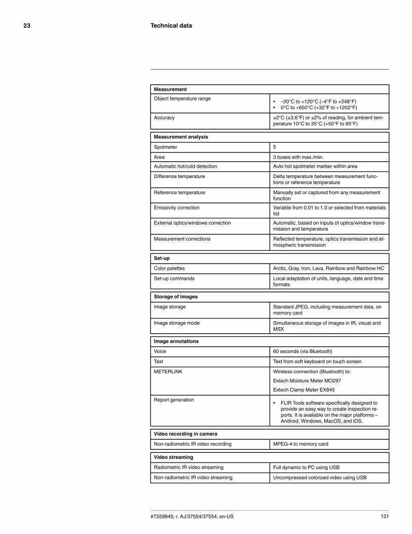
Technical data23
Measurement
Object temperature range • –20°C to +120°C (–4°F to +248°F)• 0°C to +650°C (+32°F to +1202°F)
Accuracy ±2°C (±3.6°F) or ±2% of reading, for ambient tem-perature 10°C to 35°C (+50°F to 95°F)
Measurement analysis
Spotmeter 5
Area 3 boxes with max./min.
Automatic hot/cold detection Auto hot spotmeter marker within area
Difference temperature Delta temperature between measurement func-tions or reference temperature
Reference temperature Manually set or captured from any measurementfunction
Emissivity correction Variable from 0.01 to 1.0 or selected from materialslist
External optics/windows correction Automatic, based on inputs of optics/window trans-mission and temperature
Measurement corrections Reflected temperature, optics transmission and at-mospheric transmission
Set-up
Color palettes Arctic, Gray, Iron, Lava, Rainbow and Rainbow HC
Set-up commands Local adaptation of units, language, date and timeformats
Storage of images
Image storage Standard JPEG, including measurement data, onmemory card
Image storage mode Simultaneous storage of images in IR, visual andMSX
Image annotations
Voice 60 seconds (via Bluetooth)
Text Text from soft keyboard on touch screen
METERLiNK Wireless connection (Bluetooth) to:
Extech Moisture Meter MO297
Extech Clamp Meter EX845
Report generation • FLIR Tools software specifically designed toprovide an easy way to create inspection re-ports. It is available on the major platforms –Android, Windows, MacOS, and iOS.
Video recording in camera
Non-radiometric IR video recording MPEG-4 to memory card
Video streaming
Radiometric IR video streaming Full dynamic to PC using USB
Non-radiometric IR video streaming Uncompressed colorized video using USB
#T559845; r. AJ/37554/37554; en-US 131

Technical data23
Digital camera
Built-in digital camera 3.1 Mpixels (2048 × 1536 pixels), and one LEDlight
Digital camera, focus Fixed focus
Built-in digital lens data FOV 53° × 41°
Digital camera, aspect ratio 4:3
Laser pointer
Laser Activated by dedicated button
Laser alignment Position is automatic displayed on the IR image
Laser classification Class 2
Laser type Semiconductor AlGaInP diode laser
Laser power 1 mW
Laser wavelength 635 nm (red)
Data communication interfaces
Wi-Fi Peer to peer (ad hoc) or infrastructure (network)
SD Card One card slot for removable SD memory cards
Audio Microphone headset via Bluetooth for voice anno-tation of images
USB
USB • USB-A: Connect external USB device• USB Mini-B: Data transfer to and from PC / un-
compressed colorized video
USB, standard USB Mini-B: 2.0
USB, connector type • USB-A connector• USB Mini-B connector
Composite video
Video out Composite
Video, standard CVBS (ITU-R-BT.470 PAL/SMPTE 170M NTSC)
Video, connector type 4-pole 3.5 mm jack
Radio
Wi-Fi • Standard: 802.11 b/g• Frequency range: 2412–2462 MHz• Max. output power: 15 dBm
Bluetooth Frequency range: 2402–2480 MHz
Antenna Internal
Power system
Battery type Rechargeable Li ion battery
Battery voltage 3.7 V
Battery capacity 4.4 Ah, at +20°C to +25°C (+68°F to +77°F)
Battery operating time Approx. 4 hours at +25°C (+77°F) ambient temper-ature and typical use
#T559845; r. AJ/37554/37554; en-US 132
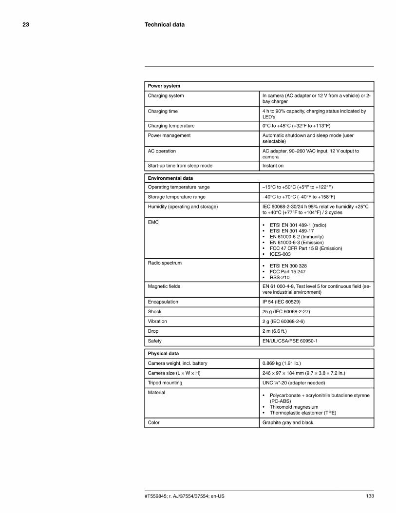
Technical data23
Power system
Charging system In camera (AC adapter or 12 V from a vehicle) or 2-bay charger
Charging time 4 h to 90% capacity, charging status indicated byLED's
Charging temperature 0°C to +45°C (+32°F to +113°F)
Power management Automatic shutdown and sleep mode (userselectable)
AC operation AC adapter, 90–260 VAC input, 12 V output tocamera
Start-up time from sleep mode Instant on
Environmental data
Operating temperature range –15°C to +50°C (+5°F to +122°F)
Storage temperature range –40°C to +70°C (–40°F to +158°F)
Humidity (operating and storage) IEC 60068-2-30/24 h 95% relative humidity +25°Cto +40°C (+77°F to +104°F) / 2 cycles
EMC • ETSI EN 301 489-1 (radio)• ETSI EN 301 489-17• EN 61000-6-2 (Immunity)• EN 61000-6-3 (Emission)• FCC 47 CFR Part 15 B (Emission)• ICES-003
Radio spectrum • ETSI EN 300 328• FCC Part 15.247• RSS-210
Magnetic fields EN 61 000-4-8, Test level 5 for continuous field (se-vere industrial environment)
Encapsulation IP 54 (IEC 60529)
Shock 25 g (IEC 60068-2-27)
Vibration 2 g (IEC 60068-2-6)
Drop 2 m (6.6 ft.)
Safety EN/UL/CSA/PSE 60950-1
Physical data
Camera weight, incl. battery 0.869 kg (1.91 lb.)
Camera size (L × W × H) 246 × 97 × 184 mm (9.7 × 3.8 × 7.2 in.)
Tripod mounting UNC ¼"-20 (adapter needed)
Material • Polycarbonate + acrylonitrile butadiene styrene(PC-ABS)
• Thixomold magnesium• Thermoplastic elastomer (TPE)
Color Graphite gray and black
#T559845; r. AJ/37554/37554; en-US 133

Technical data23
Shipping information
Packaging, type Cardboard box
List of contents • Hard transport case• Infrared camera with lens• Battery (2 ea.)• Battery charger• Handstrap• Memory card• Power supply, incl. multi-plugs• Printed documentation• USB cable• Video cable
Packaging, weight 5.5 kg (12.1 lb.)
Packaging, size 500 × 190 × 370 mm (19.7 × 7.5 × 14.6 in.)
EAN-13 4743254001169
UPC-12 845188005191
Country of origin Estonia
Supplies & accessories:
• 1196961; IR lens, f = 30 mm, 15° incl. case• 1196960; IR lens, f = 10 mm, 45° incl. case• T910814; Power supply, incl. multi plugs• T911230ACC; Memory card SDHC 4 GB• 1910423; USB cable Std A <-> Mini-B• T198509; Cigarette lighter adapter kit, 12 VDC, 1.2 m/3.9 ft.• 1910582ACC; Video cable• T197771ACC; Bluetooth Headset• T911093; Tool belt• T198125; Battery charger, incl. power supply with multi plugs (Exx, Kxx)• T199235; High-temperature lens• T198113; IR lens, 76 mm (6°) with case and mounting support for Exx• T198487; Li-Ion Battery pack 3.7V 17Wh• T198484; Pouch for FLIR Exx series• T198485; Sun shield• T198341ACC; Transport case Exx• T198486; Tripod Adapter• T199363ACC; Battery Li-ion 3.6 V, 5.2 Ah, 19 Wh• 19250-100; IR Window 2 in• 19251-100; IR Window 3 in.• 19252-100; IR Window 4 in.• 19250-200; SS IR Window 2 in.• 19251-200; SS IR Window 3 in.• 19252-200; SS IR Window 4 in.• T198586; FLIR Reporter Professional (license only)• T198584; FLIR Tools• T198583; FLIR Tools+ (download card incl. license key)• DSW-10000; FLIR IR Camera Player• APP-10002; FLIR Tools Mobile (Android Application)• APP-10004; FLIR Tools (MacOS Application)• T198697; FLIR ResearchIR Max + HSDR 4 (hardware sec. dev.)• T199014; FLIR ResearchIR Max + HSDR 4 (printed license key)• T199044; FLIR ResearchIR Max + HSDR 4 Upgrade (printed license key)• T198696; FLIR ResearchIR Max 4 (hardware sec. dev.)• T199013; FLIR ResearchIR Max 4 (printed license key)
#T559845; r. AJ/37554/37554; en-US 134

Technical data23
• T199043; FLIR ResearchIR Max 4 Upgrade (printed license key)• T198731; FLIR ResearchIR Standard 4 (hardware sec. dev.)• T199012; FLIR ResearchIR Standard 4 (printed license key)• T199042; FLIR ResearchIR Standard 4 Upgrade (printed license key)• T199233; FLIR Atlas SDK for .NET• T199234; FLIR Atlas SDK for MATLAB
#T559845; r. AJ/37554/37554; en-US 135

Mechanical drawings24
#T559845; r. AJ/37554/37554; en-US 136
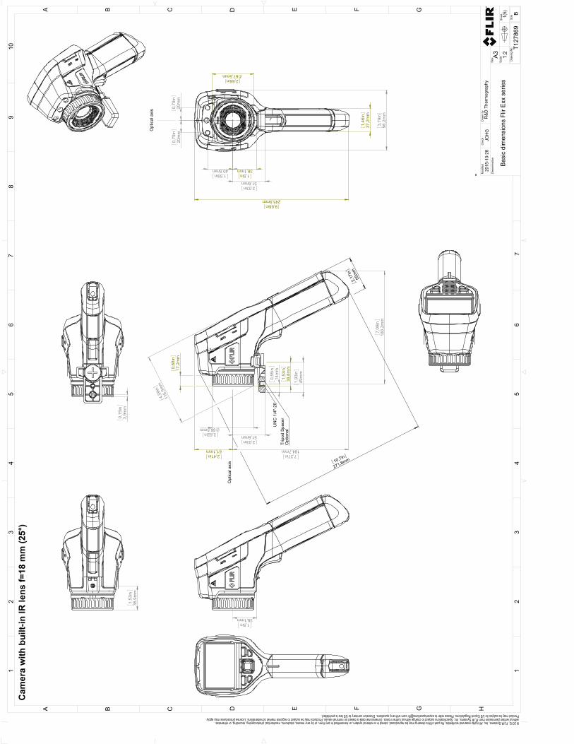
38,8
mm
1,53
in
49m
m1,
93in
17,2
mm
0,68
in
2,62in66,5mm
61,1mm2,41in
184,7mm7,27in
116,
5mm
4,59
in
51,6mm2,03in
271,8mm10,7in
55m
m2,
17in
0,
55in
14m
m
7,
09in
180,
2mm
Trip
od S
pace
rO
ptio
nal
UN
C 1
/4"-
20
Opt
ical
axi
s
40,5mm1,59in
20m
m0,
79in
20m
m0,
79in
67,5mm2,66in
38,1mm1,5in
51,6mm2,03in
37,2
mm
1,46
in
245,9mm9,68in
96,2
mm
3,79
in
Opt
ical
axi
s
0,
15in
3,9m
m
1,5in
38,1mm
1,
53in
38,9
mm
Cam
era
with
bui
lt-in
IR le
ns f=
18 m
m (2
5°)
12
34
56
78
910
16
32
54
A B C D E F G H
FC E GDA B
-
Scal
e 1:2
BSi
ze
Mod
ified
R&D
The
rmog
raph
y20
15-1
0-28
JOH
G
Basi
c di
men
sion
s Fl
ir Ex
x se
ries
T127
869
1(5)
A3D
enom
inat
ion
Dra
wn
byC
heck
Size Dra
win
g N
o.
Shee
t
7
© 2012, FLIR Systems, Inc. All rights reserved worldwide. No part of this drawing may be reproduced, stored in a retrieval system, or transmitted in any form, or by any means, electronic, mechanical, photocopying, recording, or otherwise, without written permission from FLIR Systems, Inc. Specifications subject to change without further notice. Dimensional data is based on nominal values. Products may be subject to regional market considerations. License procedures may apply. Product may be subject to US Export Regulations. Please refer to [email protected] with any questions. Diversion contrary to US law is prohibited.
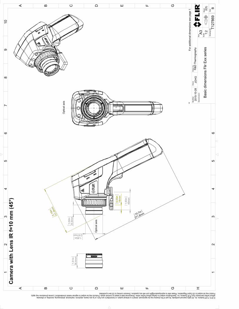
49m
m1,
93in
1,85in47mm
271,8mm10,7in
0,
55in
14m
m
5,19
in
131,
9mm
1,
02in
25,9
mm
Opt
ical
axi
s
Opt
ical
axi
s
1,
51in
38,4
mm
For a
dditi
onal
dim
ensi
ons
see
page
1
Cam
era
with
Len
s IR
f=10
mm
(45°
)
Shee
t
Dra
win
g N
o.
Size
Che
ckD
raw
n by
Den
omin
atio
nA3
2(5)
T127
869
Basi
c di
men
sion
s Fl
ir Ex
x se
ries
JOH
G20
15-1
0-28
R&D
The
rmog
raph
yM
odifi
ed
12
34
56
78
910
A B C D E F G H
13
25
4
C FB D GEA
6Si
ze
B
1:2
Scal
e
© 2012, FLIR Systems, Inc. All rights reserved worldwide. No part of this drawing may be reproduced, stored in a retrieval system, or transmitted in any form, or by any means, electronic, mechanical, photocopying, recording, or otherwise, without written permission from FLIR Systems, Inc. Specifications subject to change without further notice. Dimensional data is based on nominal values. Products may be subject to regional market considerations. License procedures may apply. Product may be subject to US Export Regulations. Please refer to [email protected] with any questions. Diversion contrary to US law is prohibited.
-
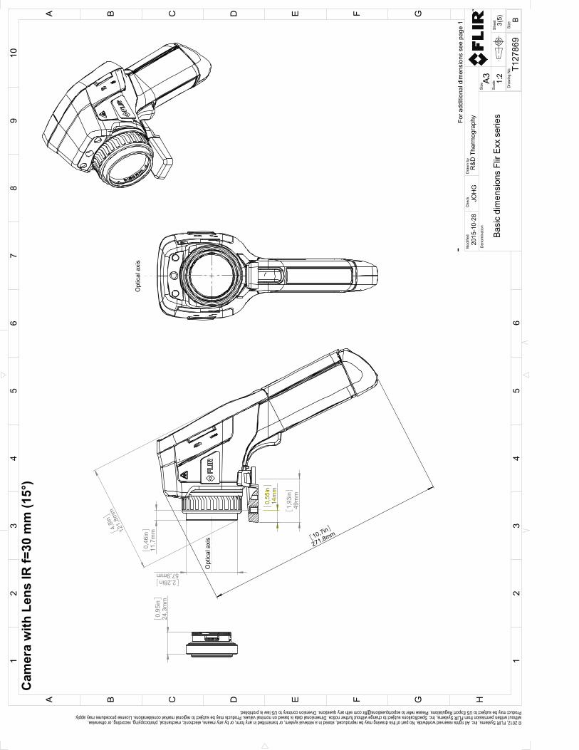
49m
m1,
93in
271,8mm10,7in
0,
55in
14m
m
0,
46in
11,7
mm
4,8i
n
121,
8mm
2,28in
57,9mm
Opt
ical
axi
s
Opt
ical
axi
s
0,
95in
24,3
mm
For a
dditi
onal
dim
ensi
ons
see
page
1
Cam
era
with
Len
s IR
f=30
mm
(15°
)
Shee
t
Dra
win
g N
o.
Size
Che
ckD
raw
n by
Den
omin
atio
nA3
3(5)
T127
869
Basi
c di
men
sion
s Fl
ir Ex
x se
ries
JOH
G20
15-1
0-28
R&D
The
rmog
raph
yM
odifi
ed
12
34
56
78
910
A B C D E F G H
13
25
4
C FB D GEA
6Si
ze
B
1:2
Scal
e
© 2012, FLIR Systems, Inc. All rights reserved worldwide. No part of this drawing may be reproduced, stored in a retrieval system, or transmitted in any form, or by any means, electronic, mechanical, photocopying, recording, or otherwise, without written permission from FLIR Systems, Inc. Specifications subject to change without further notice. Dimensional data is based on nominal values. Products may be subject to regional market considerations. License procedures may apply. Product may be subject to US Export Regulations. Please refer to [email protected] with any questions. Diversion contrary to US law is prohibited.
-
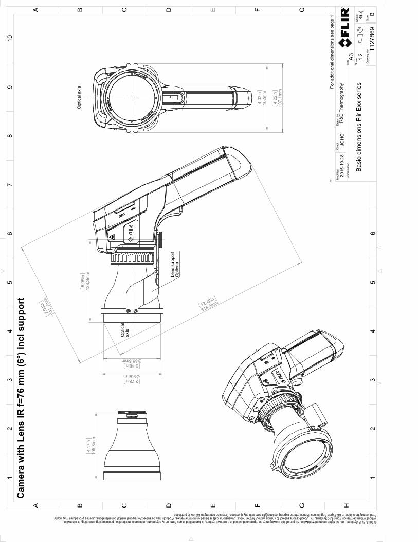
3,48in88,5mm
3,78in96mm
7,94
in
201,
7mm
5,
05in
128,
3mm
12,42in
315,5mm
Lens
sup
port
Opt
iona
l
Opt
ical
ax
is
4,
22in
107,
1mm
4,
02in
102m
m
Opt
ical
axi
s
4,
17in
105,
8mm
For a
dditi
onal
dim
ensi
ons
see
page
1
Cam
era
with
Len
s IR
f=76
mm
(6°)
incl
sup
port
Shee
t
Dra
win
g N
o.
Size
Che
ckD
raw
n by
Den
omin
atio
nA3
4(5)
T127
869
Basi
c di
men
sion
s Fl
ir Ex
x se
ries
JOH
G20
15-1
0-28
R&D
The
rmog
raph
yM
odifi
ed
12
34
56
78
910
A B C D E F G H
13
25
4
C FB D GEA
6Si
ze
B
1:2
Scal
e
© 2012, FLIR Systems, Inc. All rights reserved worldwide. No part of this drawing may be reproduced, stored in a retrieval system, or transmitted in any form, or by any means, electronic, mechanical, photocopying, recording, or otherwise, without written permission from FLIR Systems, Inc. Specifications subject to change without further notice. Dimensional data is based on nominal values. Products may be subject to regional market considerations. License procedures may apply. Product may be subject to US Export Regulations. Please refer to [email protected] with any questions. Diversion contrary to US law is prohibited.
-

CE Declaration of conformity25
#T559845; r. AJ/37554/37554; en-US 141
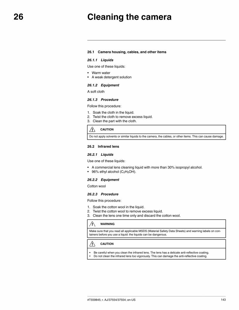
Cleaning the camera26
26.1 Camera housing, cables, and other items
26.1.1 Liquids
Use one of these liquids:
• Warm water• A weak detergent solution
26.1.2 Equipment
A soft cloth
26.1.3 Procedure
Follow this procedure:
1. Soak the cloth in the liquid.2. Twist the cloth to remove excess liquid.3. Clean the part with the cloth.
CAUTION
Do not apply solvents or similar liquids to the camera, the cables, or other items. This can cause damage.
26.2 Infrared lens
26.2.1 Liquids
Use one of these liquids:
• A commercial lens cleaning liquid with more than 30% isopropyl alcohol.• 96% ethyl alcohol (C2H5OH).
26.2.2 Equipment
Cotton wool
26.2.3 Procedure
Follow this procedure:
1. Soak the cotton wool in the liquid.2. Twist the cotton wool to remove excess liquid.3. Clean the lens one time only and discard the cotton wool.
WARNING
Make sure that you read all applicable MSDS (Material Safety Data Sheets) and warning labels on con-tainers before you use a liquid: the liquids can be dangerous.
CAUTION
• Be careful when you clean the infrared lens. The lens has a delicate anti-reflective coating.• Do not clean the infrared lens too vigorously. This can damage the anti-reflective coating.
#T559845; r. AJ/37554/37554; en-US 143
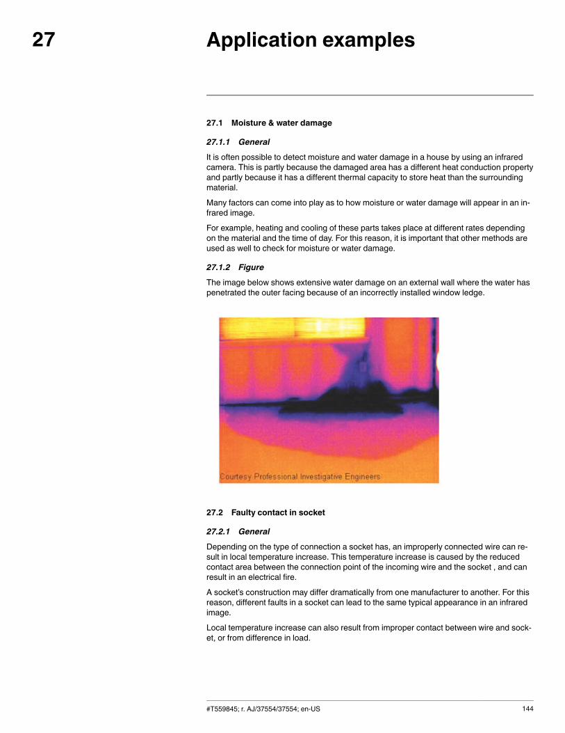
Application examples27
27.1 Moisture & water damage
27.1.1 General
It is often possible to detect moisture and water damage in a house by using an infraredcamera. This is partly because the damaged area has a different heat conduction propertyand partly because it has a different thermal capacity to store heat than the surroundingmaterial.
Many factors can come into play as to how moisture or water damage will appear in an in-frared image.
For example, heating and cooling of these parts takes place at different rates dependingon the material and the time of day. For this reason, it is important that other methods areused as well to check for moisture or water damage.
27.1.2 Figure
The image below shows extensive water damage on an external wall where the water haspenetrated the outer facing because of an incorrectly installed window ledge.
27.2 Faulty contact in socket
27.2.1 General
Depending on the type of connection a socket has, an improperly connected wire can re-sult in local temperature increase. This temperature increase is caused by the reducedcontact area between the connection point of the incoming wire and the socket , and canresult in an electrical fire.
A socket’s construction may differ dramatically from one manufacturer to another. For thisreason, different faults in a socket can lead to the same typical appearance in an infraredimage.
Local temperature increase can also result from improper contact between wire and sock-et, or from difference in load.
#T559845; r. AJ/37554/37554; en-US 144
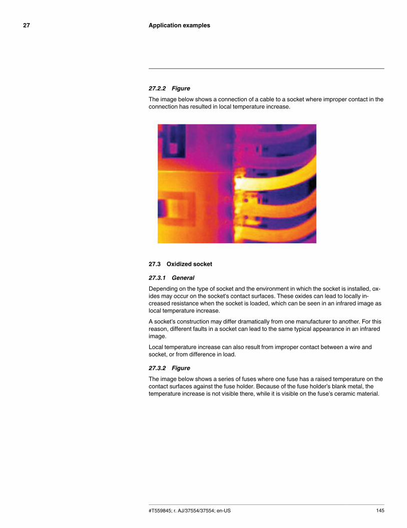
Application examples27
27.2.2 Figure
The image below shows a connection of a cable to a socket where improper contact in theconnection has resulted in local temperature increase.
27.3 Oxidized socket
27.3.1 General
Depending on the type of socket and the environment in which the socket is installed, ox-ides may occur on the socket's contact surfaces. These oxides can lead to locally in-creased resistance when the socket is loaded, which can be seen in an infrared image aslocal temperature increase.
A socket’s construction may differ dramatically from one manufacturer to another. For thisreason, different faults in a socket can lead to the same typical appearance in an infraredimage.
Local temperature increase can also result from improper contact between a wire andsocket, or from difference in load.
27.3.2 Figure
The image below shows a series of fuses where one fuse has a raised temperature on thecontact surfaces against the fuse holder. Because of the fuse holder’s blank metal, thetemperature increase is not visible there, while it is visible on the fuse’s ceramic material.
#T559845; r. AJ/37554/37554; en-US 145
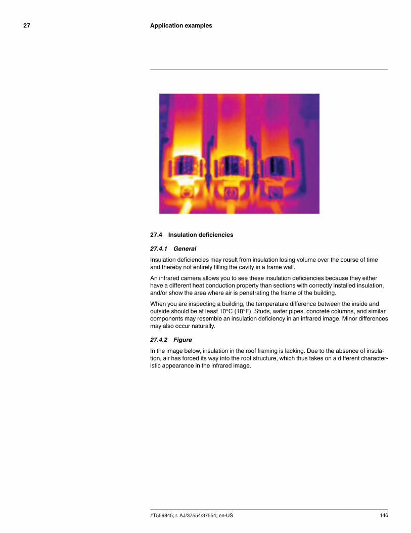
Application examples27
27.4 Insulation deficiencies
27.4.1 General
Insulation deficiencies may result from insulation losing volume over the course of timeand thereby not entirely filling the cavity in a frame wall.
An infrared camera allows you to see these insulation deficiencies because they eitherhave a different heat conduction property than sections with correctly installed insulation,and/or show the area where air is penetrating the frame of the building.
When you are inspecting a building, the temperature difference between the inside andoutside should be at least 10°C (18°F). Studs, water pipes, concrete columns, and similarcomponents may resemble an insulation deficiency in an infrared image. Minor differencesmay also occur naturally.
27.4.2 Figure
In the image below, insulation in the roof framing is lacking. Due to the absence of insula-tion, air has forced its way into the roof structure, which thus takes on a different character-istic appearance in the infrared image.
#T559845; r. AJ/37554/37554; en-US 146
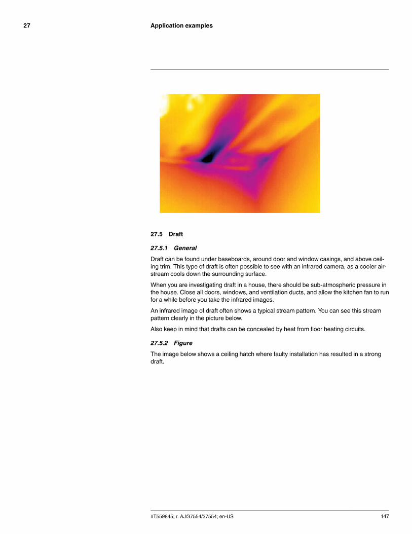
Application examples27
27.5 Draft
27.5.1 General
Draft can be found under baseboards, around door and window casings, and above ceil-ing trim. This type of draft is often possible to see with an infrared camera, as a cooler air-stream cools down the surrounding surface.
When you are investigating draft in a house, there should be sub-atmospheric pressure inthe house. Close all doors, windows, and ventilation ducts, and allow the kitchen fan to runfor a while before you take the infrared images.
An infrared image of draft often shows a typical stream pattern. You can see this streampattern clearly in the picture below.
Also keep in mind that drafts can be concealed by heat from floor heating circuits.
27.5.2 Figure
The image below shows a ceiling hatch where faulty installation has resulted in a strongdraft.
#T559845; r. AJ/37554/37554; en-US 147
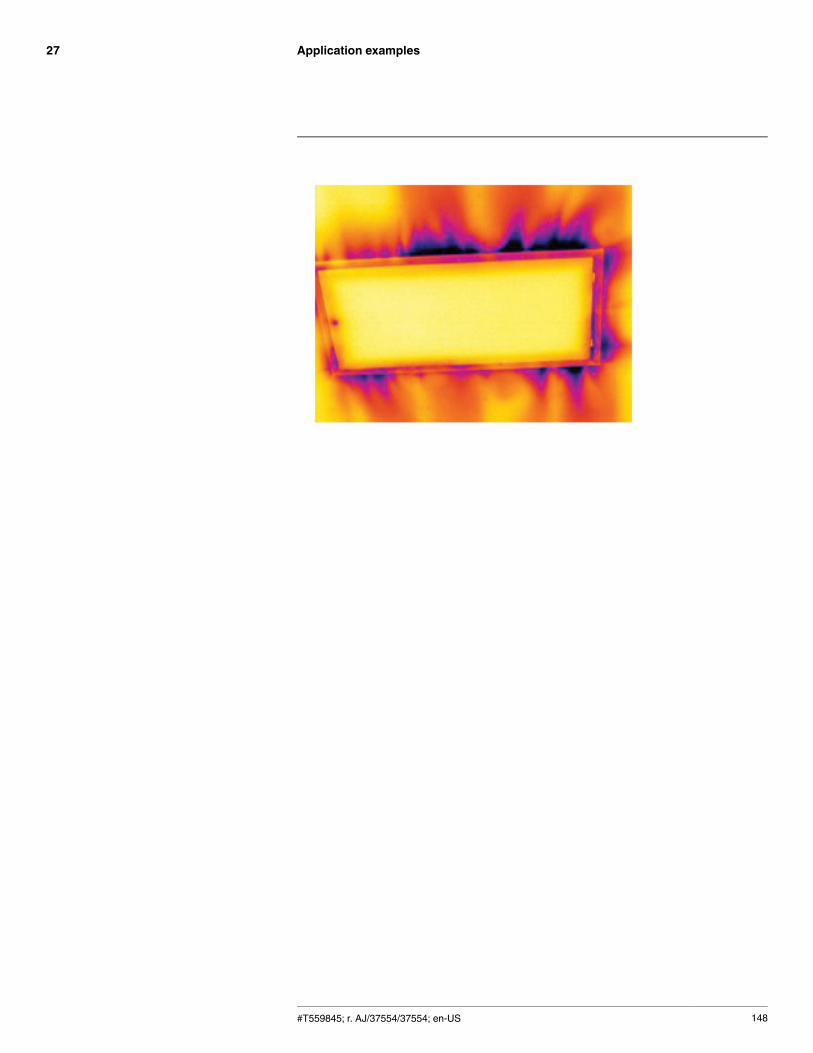
Application examples27
#T559845; r. AJ/37554/37554; en-US 148
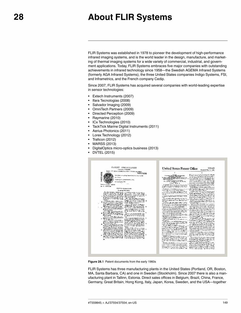
About FLIR Systems28
FLIR Systems was established in 1978 to pioneer the development of high-performanceinfrared imaging systems, and is the world leader in the design, manufacture, and market-ing of thermal imaging systems for a wide variety of commercial, industrial, and govern-ment applications. Today, FLIR Systems embraces five major companies with outstandingachievements in infrared technology since 1958—the Swedish AGEMA Infrared Systems(formerly AGA Infrared Systems), the three United States companies Indigo Systems, FSI,and Inframetrics, and the French company Cedip.
Since 2007, FLIR Systems has acquired several companies with world-leading expertisein sensor technologies:
• Extech Instruments (2007)• Ifara Tecnologías (2008)• Salvador Imaging (2009)• OmniTech Partners (2009)• Directed Perception (2009)• Raymarine (2010)• ICx Technologies (2010)• TackTick Marine Digital Instruments (2011)• Aerius Photonics (2011)• Lorex Technology (2012)• Traficon (2012)• MARSS (2013)• DigitalOptics micro-optics business (2013)• DVTEL (2015)
Figure 28.1 Patent documents from the early 1960s
FLIR Systems has three manufacturing plants in the United States (Portland, OR, Boston,MA, Santa Barbara, CA) and one in Sweden (Stockholm). Since 2007 there is also a man-ufacturing plant in Tallinn, Estonia. Direct sales offices in Belgium, Brazil, China, France,Germany, Great Britain, Hong Kong, Italy, Japan, Korea, Sweden, and the USA—together
#T559845; r. AJ/37554/37554; en-US 149
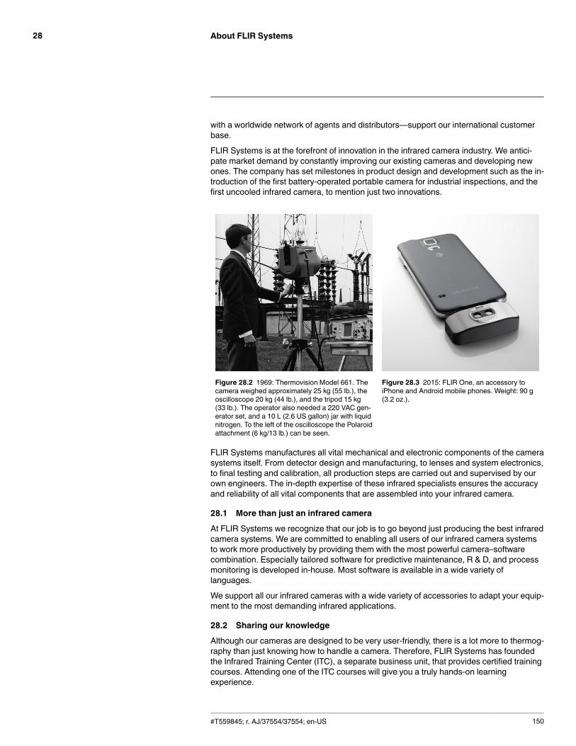
About FLIR Systems28
with a worldwide network of agents and distributors—support our international customerbase.
FLIR Systems is at the forefront of innovation in the infrared camera industry. We antici-pate market demand by constantly improving our existing cameras and developing newones. The company has set milestones in product design and development such as the in-troduction of the first battery-operated portable camera for industrial inspections, and thefirst uncooled infrared camera, to mention just two innovations.
Figure 28.2 1969: Thermovision Model 661. Thecamera weighed approximately 25 kg (55 lb.), theoscilloscope 20 kg (44 lb.), and the tripod 15 kg(33 lb.). The operator also needed a 220 VAC gen-erator set, and a 10 L (2.6 US gallon) jar with liquidnitrogen. To the left of the oscilloscope the Polaroidattachment (6 kg/13 lb.) can be seen.
Figure 28.3 2015: FLIR One, an accessory toiPhone and Android mobile phones. Weight: 90 g(3.2 oz.).
FLIR Systems manufactures all vital mechanical and electronic components of the camerasystems itself. From detector design and manufacturing, to lenses and system electronics,to final testing and calibration, all production steps are carried out and supervised by ourown engineers. The in-depth expertise of these infrared specialists ensures the accuracyand reliability of all vital components that are assembled into your infrared camera.
28.1 More than just an infrared camera
At FLIR Systems we recognize that our job is to go beyond just producing the best infraredcamera systems. We are committed to enabling all users of our infrared camera systemsto work more productively by providing them with the most powerful camera–softwarecombination. Especially tailored software for predictive maintenance, R & D, and processmonitoring is developed in-house. Most software is available in a wide variety oflanguages.
We support all our infrared cameras with a wide variety of accessories to adapt your equip-ment to the most demanding infrared applications.
28.2 Sharing our knowledge
Although our cameras are designed to be very user-friendly, there is a lot more to thermog-raphy than just knowing how to handle a camera. Therefore, FLIR Systems has foundedthe Infrared Training Center (ITC), a separate business unit, that provides certified trainingcourses. Attending one of the ITC courses will give you a truly hands-on learningexperience.
#T559845; r. AJ/37554/37554; en-US 150
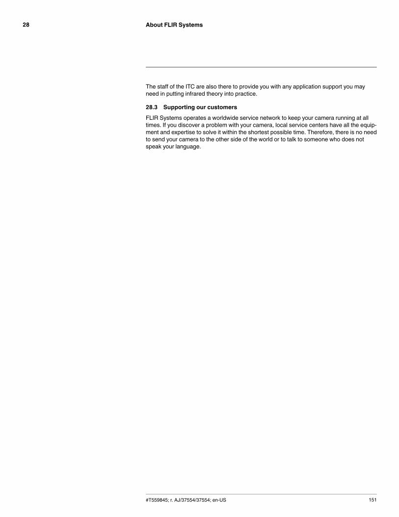
About FLIR Systems28
The staff of the ITC are also there to provide you with any application support you mayneed in putting infrared theory into practice.
28.3 Supporting our customers
FLIR Systems operates a worldwide service network to keep your camera running at alltimes. If you discover a problem with your camera, local service centers have all the equip-ment and expertise to solve it within the shortest possible time. Therefore, there is no needto send your camera to the other side of the world or to talk to someone who does notspeak your language.
#T559845; r. AJ/37554/37554; en-US 151
Glossary29
absorption (ab-sorption factor)
The amount of radiation absorbed by an object relative to the re-ceived radiation. A number between 0 and 1.
atmosphere The gases between the object being measured and the camera, nor-mally air.
autoadjust A function making a camera perform an internal image correction.
autopalette The IR image is shown with an uneven spread of colors, displayingcold objects as well as hot ones at the same time.
blackbody Totally non-reflective object. All its radiation is due to its owntemperature.
blackbodyradiator
An IR radiating equipment with blackbody properties used to calibrateIR cameras.
calculated at-mospherictransmission
A transmission value computed from the temperature, the relative hu-midity of air and the distance to the object.
cavity radiator A bottle shaped radiator with an absorbing inside, viewed through thebottleneck.
colortemperature
The temperature for which the color of a blackbody matches a specif-ic color.
conduction The process that makes heat diffuse into a material.
continuousadjust
A function that adjusts the image. The function works all the time,continuously adjusting brightness and contrast according to the im-age content.
convection Convection is a heat transfer mode where a fluid is brought into mo-tion, either by gravity or another force, thereby transferring heat fromone place to another.
dual isotherm An isotherm with two color bands, instead of one.emissivity(emissivityfactor)
The amount of radiation coming from an object, compared to that of ablackbody. A number between 0 and 1.
emittance Amount of energy emitted from an object per unit of time and area(W/m2)
environment Objects and gases that emit radiation towards the object beingmeasured.
estimated at-mospherictransmission
A transmission value, supplied by a user, replacing a calculated one
external optics Extra lenses, filters, heat shields etc. that can be put between thecamera and the object being measured.
filter A material transparent only to some of the infrared wavelengths.
FOV Field of view: The horizontal angle that can be viewed through an IRlens.
FPA Focal plane array: A type of IR detector.
graybody An object that emits a fixed fraction of the amount of energy of ablackbody for each wavelength.
#T559845; r. AJ/37554/37554; en-US 152
Glossary29
IFOV Instantaneous field of view: A measure of the geometrical resolutionof an IR camera.
image correc-tion (internal orexternal)
A way of compensating for sensitivity differences in various parts oflive images and also of stabilizing the camera.
infrared Non-visible radiation, having a wavelength from about 2–13 μm.
IR infraredisotherm A function highlighting those parts of an image that fall above, below
or between one or more temperature intervals.
isothermalcavity
A bottle-shaped radiator with a uniform temperature viewed throughthe bottleneck.
Laser LocatIR An electrically powered light source on the camera that emits laser ra-diation in a thin, concentrated beam to point at certain parts of the ob-ject in front of the camera.
laser pointer An electrically powered light source on the camera that emits laser ra-diation in a thin, concentrated beam to point at certain parts of the ob-ject in front of the camera.
level The center value of the temperature scale, usually expressed as asignal value.
manual adjust A way to adjust the image by manually changing certain parameters.
NETD Noise equivalent temperature difference. A measure of the imagenoise level of an IR camera.
noise Undesired small disturbance in the infrared image
objectparameters
A set of values describing the circumstances under which the meas-urement of an object was made, and the object itself (such as emis-sivity, reflected apparent temperature, distance etc.)
object signal A non-calibrated value related to the amount of radiation received bythe camera from the object.
palette The set of colors used to display an IR image.
pixel Stands for picture element. One single spot in an image.
radiance Amount of energy emitted from an object per unit of time, area andangle (W/m2/sr)
radiant power Amount of energy emitted from an object per unit of time (W)
radiation The process by which electromagnetic energy, is emitted by an objector a gas.
radiator A piece of IR radiating equipment.range The current overall temperature measurement limitation of an IR cam-
era. Cameras can have several ranges. Expressed as two blackbodytemperatures that limit the current calibration.
referencetemperature
A temperature which the ordinary measured values can be comparedwith.
reflection The amount of radiation reflected by an object relative to the receivedradiation. A number between 0 and 1.
#T559845; r. AJ/37554/37554; en-US 153
Glossary29
relativehumidity
Relative humidity represents the ratio between the current water va-pour mass in the air and the maximum it may contain in saturationconditions.
saturationcolor
The areas that contain temperatures outside the present level/spansettings are colored with the saturation colors. The saturation colorscontain an ‘overflow’ color and an ‘underflow’ color. There is also athird red saturation color that marks everything saturated by the de-tector indicating that the range should probably be changed.
span The interval of the temperature scale, usually expressed as a signalvalue.
spectral (radi-ant) emittance
Amount of energy emitted from an object per unit of time, area andwavelength (W/m2/μm)
temperaturedifference, ordifference oftemperature.
A value which is the result of a subtraction between two temperaturevalues.
temperaturerange
The current overall temperature measurement limitation of an IR cam-era. Cameras can have several ranges. Expressed as two blackbodytemperatures that limit the current calibration.
temperaturescale
The way in which an IR image currently is displayed. Expressed astwo temperature values limiting the colors.
thermogram infrared image
transmission(or transmit-tance) factor
Gases and materials can be more or less transparent. Transmissionis the amount of IR radiation passing through them. A number be-tween 0 and 1.
transparentisotherm
An isotherm showing a linear spread of colors, instead of covering thehighlighted parts of the image.
visual Refers to the video mode of a IR camera, as opposed to the normal,thermographic mode. When a camera is in video mode it captures or-dinary video images, while thermographic images are captured whenthe camera is in IR mode.
#T559845; r. AJ/37554/37554; en-US 154
Thermographic measurementtechniques
30
30.1 Introduction
An infrared camera measures and images the emitted infrared radiation from an object.The fact that radiation is a function of object surface temperature makes it possible for thecamera to calculate and display this temperature.
However, the radiation measured by the camera does not only depend on the temperatureof the object but is also a function of the emissivity. Radiation also originates from the sur-roundings and is reflected in the object. The radiation from the object and the reflected ra-diation will also be influenced by the absorption of the atmosphere.
To measure temperature accurately, it is therefore necessary to compensate for the effectsof a number of different radiation sources. This is done on-line automatically by the cam-era. The following object parameters must, however, be supplied for the camera:
• The emissivity of the object• The reflected apparent temperature• The distance between the object and the camera• The relative humidity• Temperature of the atmosphere
30.2 Emissivity
The most important object parameter to set correctly is the emissivity which, in short, is ameasure of how much radiation is emitted from the object, compared to that from a perfectblackbody of the same temperature.
Normally, object materials and surface treatments exhibit emissivity ranging from approxi-mately 0.1 to 0.95. A highly polished (mirror) surface falls below 0.1, while an oxidized orpainted surface has a higher emissivity. Oil-based paint, regardless of color in the visiblespectrum, has an emissivity over 0.9 in the infrared. Human skin exhibits an emissivity0.97 to 0.98.
Non-oxidized metals represent an extreme case of perfect opacity and high reflexivity,which does not vary greatly with wavelength. Consequently, the emissivity of metals is low– only increasing with temperature. For non-metals, emissivity tends to be high, and de-creases with temperature.
30.2.1 Finding the emissivity of a sample
30.2.1.1 Step 1: Determining reflected apparent temperature
Use one of the following two methods to determine reflected apparent temperature:
#T559845; r. AJ/37554/37554; en-US 155
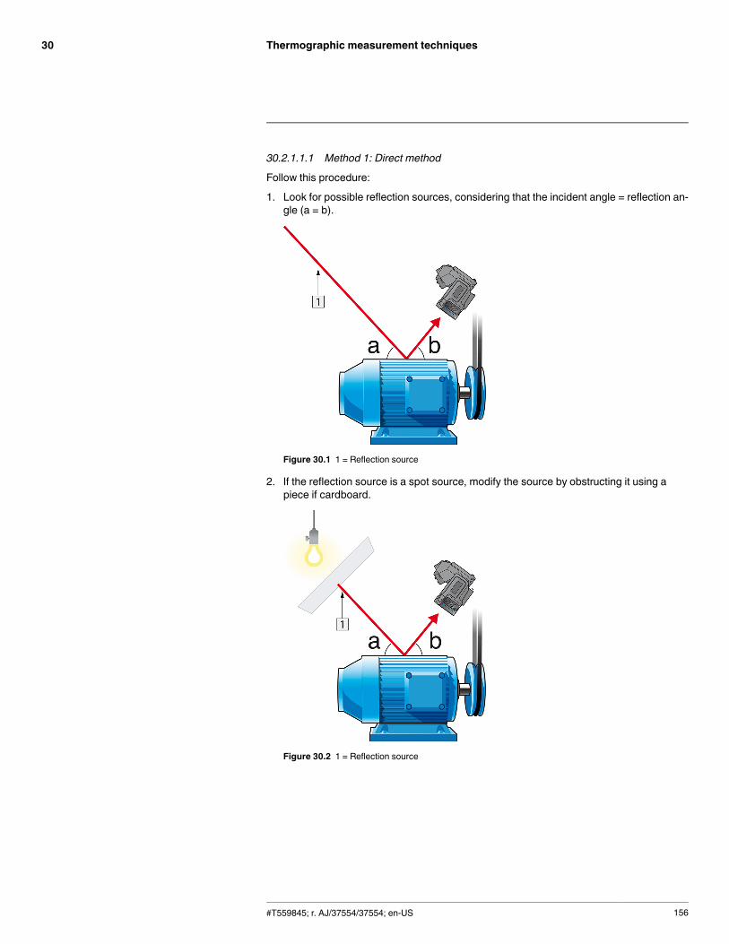
Thermographic measurement techniques30
30.2.1.1.1 Method 1: Direct method
Follow this procedure:
1. Look for possible reflection sources, considering that the incident angle = reflection an-gle (a = b).
Figure 30.1 1 = Reflection source
2. If the reflection source is a spot source, modify the source by obstructing it using apiece if cardboard.
Figure 30.2 1 = Reflection source
#T559845; r. AJ/37554/37554; en-US 156
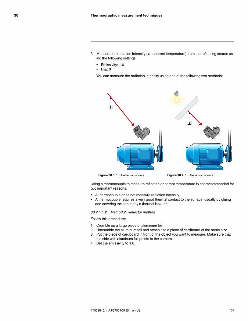
Thermographic measurement techniques30
3. Measure the radiation intensity (= apparent temperature) from the reflecting source us-ing the following settings:
• Emissivity: 1.0• Dobj: 0
You can measure the radiation intensity using one of the following two methods:
Figure 30.3 1 = Reflection source Figure 30.4 1 = Reflection source
Using a thermocouple to measure reflected apparent temperature is not recommended fortwo important reasons:
• A thermocouple does not measure radiation intensity• A thermocouple requires a very good thermal contact to the surface, usually by gluingand covering the sensor by a thermal isolator.
30.2.1.1.2 Method 2: Reflector method
Follow this procedure:
1. Crumble up a large piece of aluminum foil.2. Uncrumble the aluminum foil and attach it to a piece of cardboard of the same size.3. Put the piece of cardboard in front of the object you want to measure. Make sure that
the side with aluminum foil points to the camera.4. Set the emissivity to 1.0.
#T559845; r. AJ/37554/37554; en-US 157
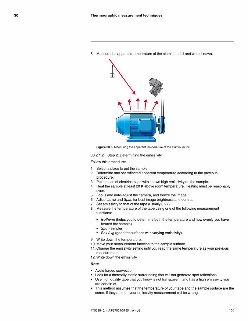
Thermographic measurement techniques30
5. Measure the apparent temperature of the aluminum foil and write it down.
Figure 30.5 Measuring the apparent temperature of the aluminum foil.
30.2.1.2 Step 2: Determining the emissivity
Follow this procedure:
1. Select a place to put the sample.2. Determine and set reflected apparent temperature according to the previous
procedure.3. Put a piece of electrical tape with known high emissivity on the sample.4. Heat the sample at least 20 K above room temperature. Heating must be reasonably
even.5. Focus and auto-adjust the camera, and freeze the image.6. Adjust Level and Span for best image brightness and contrast.7. Set emissivity to that of the tape (usually 0.97).8. Measure the temperature of the tape using one of the following measurement
functions:
• Isotherm (helps you to determine both the temperature and how evenly you haveheated the sample)
• Spot (simpler)• Box Avg (good for surfaces with varying emissivity).
9. Write down the temperature.10. Move your measurement function to the sample surface.11. Change the emissivity setting until you read the same temperature as your previous
measurement.12.Write down the emissivity.
Note
• Avoid forced convection• Look for a thermally stable surrounding that will not generate spot reflections• Use high quality tape that you know is not transparent, and has a high emissivity youare certain of
• This method assumes that the temperature of your tape and the sample surface are thesame. If they are not, your emissivity measurement will be wrong.
#T559845; r. AJ/37554/37554; en-US 158
Thermographic measurement techniques30
30.3 Reflected apparent temperature
This parameter is used to compensate for the radiation reflected in the object. If the emis-sivity is low and the object temperature relatively far from that of the reflected it will be im-portant to set and compensate for the reflected apparent temperature correctly.
30.4 Distance
The distance is the distance between the object and the front lens of the camera. This pa-rameter is used to compensate for the following two facts:
• That radiation from the target is absorbed by the atmosphere between the object andthe camera.
• That radiation from the atmosphere itself is detected by the camera.
30.5 Relative humidity
The camera can also compensate for the fact that the transmittance is also dependent onthe relative humidity of the atmosphere. To do this set the relative humidity to the correctvalue. For short distances and normal humidity the relative humidity can normally be left ata default value of 50%.
30.6 Other parameters
In addition, some cameras and analysis programs from FLIR Systems allow you to com-pensate for the following parameters:
• Atmospheric temperature – i.e. the temperature of the atmosphere between the cameraand the target
• External optics temperature – i.e. the temperature of any external lenses or windowsused in front of the camera
• External optics transmittance – i.e. the transmission of any external lenses or windowsused in front of the camera
#T559845; r. AJ/37554/37554; en-US 159
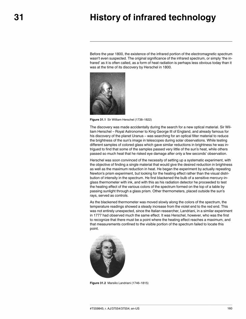
History of infrared technology31
Before the year 1800, the existence of the infrared portion of the electromagnetic spectrumwasn't even suspected. The original significance of the infrared spectrum, or simply ‘the in-frared’ as it is often called, as a form of heat radiation is perhaps less obvious today than itwas at the time of its discovery by Herschel in 1800.
Figure 31.1 Sir William Herschel (1738–1822)
The discovery was made accidentally during the search for a new optical material. Sir Wil-liam Herschel – Royal Astronomer to King George III of England, and already famous forhis discovery of the planet Uranus – was searching for an optical filter material to reducethe brightness of the sun’s image in telescopes during solar observations. While testingdifferent samples of colored glass which gave similar reductions in brightness he was in-trigued to find that some of the samples passed very little of the sun’s heat, while otherspassed so much heat that he risked eye damage after only a few seconds’ observation.
Herschel was soon convinced of the necessity of setting up a systematic experiment, withthe objective of finding a single material that would give the desired reduction in brightnessas well as the maximum reduction in heat. He began the experiment by actually repeatingNewton’s prism experiment, but looking for the heating effect rather than the visual distri-bution of intensity in the spectrum. He first blackened the bulb of a sensitive mercury-in-glass thermometer with ink, and with this as his radiation detector he proceeded to testthe heating effect of the various colors of the spectrum formed on the top of a table bypassing sunlight through a glass prism. Other thermometers, placed outside the sun’srays, served as controls.
As the blackened thermometer was moved slowly along the colors of the spectrum, thetemperature readings showed a steady increase from the violet end to the red end. Thiswas not entirely unexpected, since the Italian researcher, Landriani, in a similar experimentin 1777 had observed much the same effect. It was Herschel, however, who was the firstto recognize that there must be a point where the heating effect reaches a maximum, andthat measurements confined to the visible portion of the spectrum failed to locate thispoint.
Figure 31.2 Marsilio Landriani (1746–1815)
#T559845; r. AJ/37554/37554; en-US 160
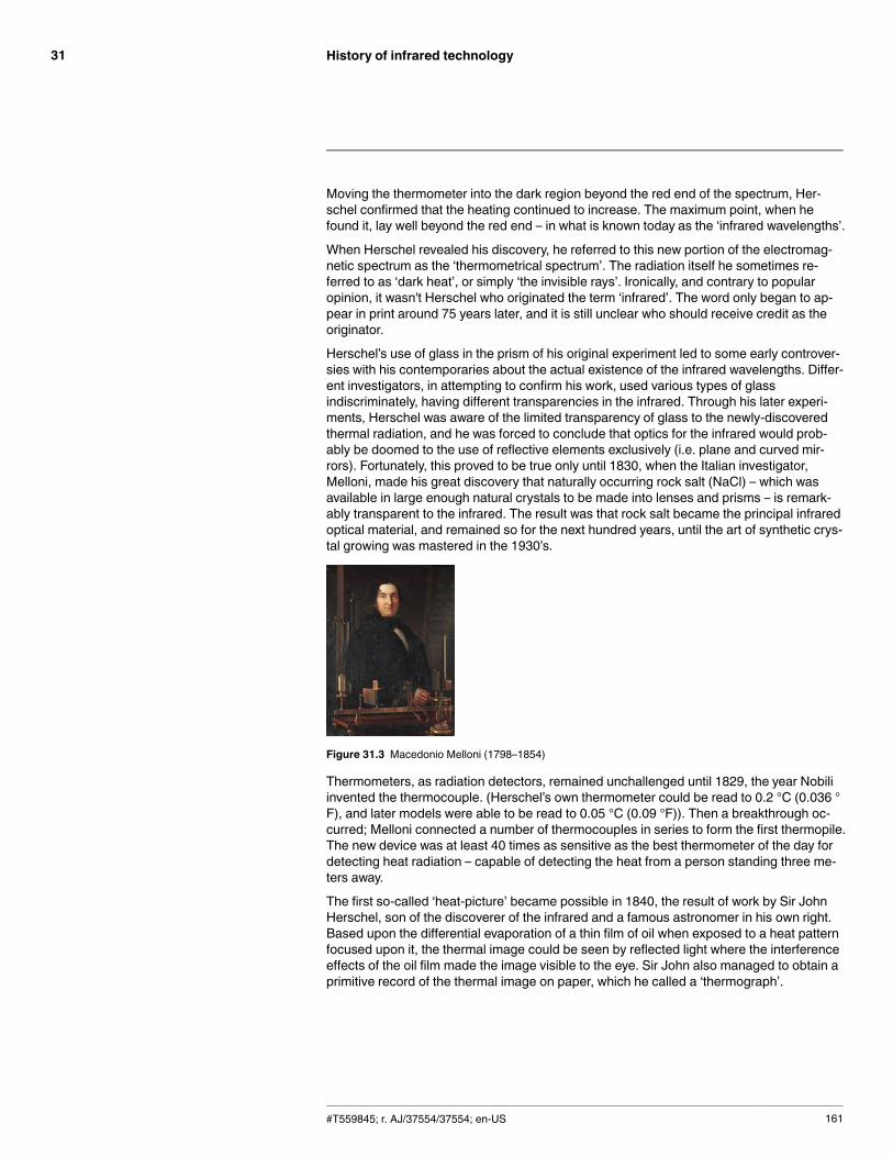
History of infrared technology31
Moving the thermometer into the dark region beyond the red end of the spectrum, Her-schel confirmed that the heating continued to increase. The maximum point, when hefound it, lay well beyond the red end – in what is known today as the ‘infrared wavelengths’.
When Herschel revealed his discovery, he referred to this new portion of the electromag-netic spectrum as the ‘thermometrical spectrum’. The radiation itself he sometimes re-ferred to as ‘dark heat’, or simply ‘the invisible rays’. Ironically, and contrary to popularopinion, it wasn't Herschel who originated the term ‘infrared’. The word only began to ap-pear in print around 75 years later, and it is still unclear who should receive credit as theoriginator.
Herschel’s use of glass in the prism of his original experiment led to some early controver-sies with his contemporaries about the actual existence of the infrared wavelengths. Differ-ent investigators, in attempting to confirm his work, used various types of glassindiscriminately, having different transparencies in the infrared. Through his later experi-ments, Herschel was aware of the limited transparency of glass to the newly-discoveredthermal radiation, and he was forced to conclude that optics for the infrared would prob-ably be doomed to the use of reflective elements exclusively (i.e. plane and curved mir-rors). Fortunately, this proved to be true only until 1830, when the Italian investigator,Melloni, made his great discovery that naturally occurring rock salt (NaCl) – which wasavailable in large enough natural crystals to be made into lenses and prisms – is remark-ably transparent to the infrared. The result was that rock salt became the principal infraredoptical material, and remained so for the next hundred years, until the art of synthetic crys-tal growing was mastered in the 1930’s.
Figure 31.3 Macedonio Melloni (1798–1854)
Thermometers, as radiation detectors, remained unchallenged until 1829, the year Nobiliinvented the thermocouple. (Herschel’s own thermometer could be read to 0.2 °C (0.036 °F), and later models were able to be read to 0.05 °C (0.09 °F)). Then a breakthrough oc-curred; Melloni connected a number of thermocouples in series to form the first thermopile.The new device was at least 40 times as sensitive as the best thermometer of the day fordetecting heat radiation – capable of detecting the heat from a person standing three me-ters away.
The first so-called ‘heat-picture’ became possible in 1840, the result of work by Sir JohnHerschel, son of the discoverer of the infrared and a famous astronomer in his own right.Based upon the differential evaporation of a thin film of oil when exposed to a heat patternfocused upon it, the thermal image could be seen by reflected light where the interferenceeffects of the oil film made the image visible to the eye. Sir John also managed to obtain aprimitive record of the thermal image on paper, which he called a ‘thermograph’.
#T559845; r. AJ/37554/37554; en-US 161
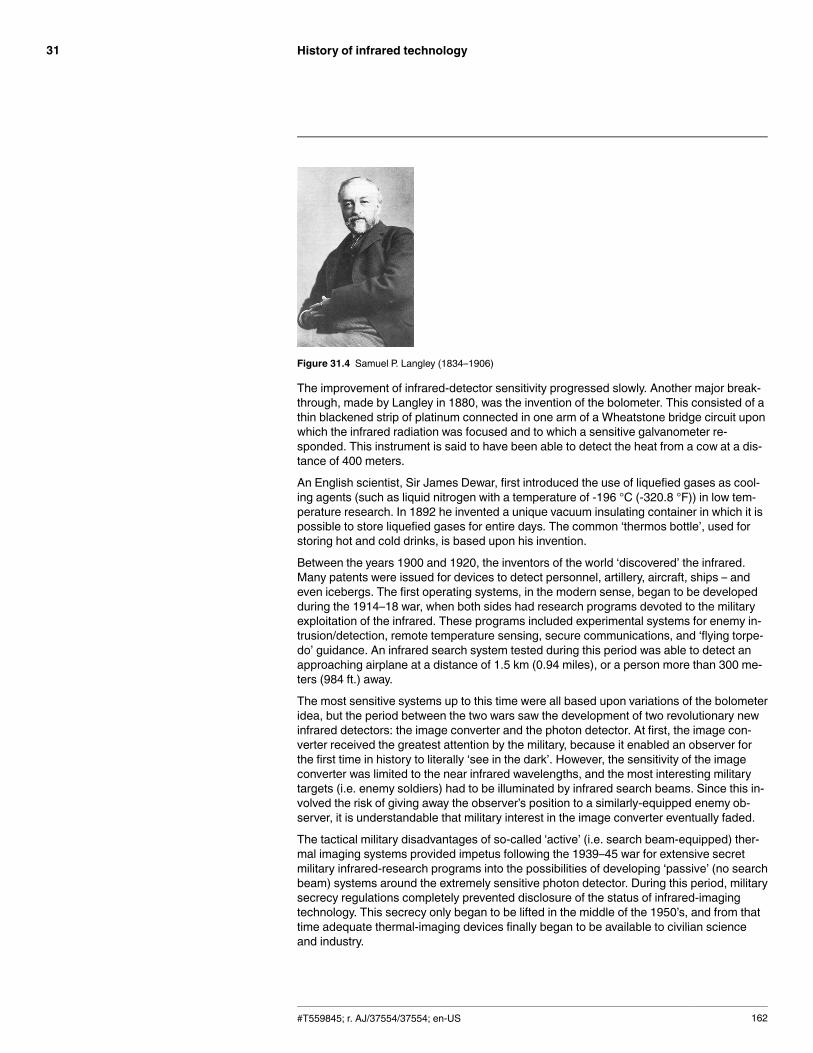
History of infrared technology31
Figure 31.4 Samuel P. Langley (1834–1906)
The improvement of infrared-detector sensitivity progressed slowly. Another major break-through, made by Langley in 1880, was the invention of the bolometer. This consisted of athin blackened strip of platinum connected in one arm of a Wheatstone bridge circuit uponwhich the infrared radiation was focused and to which a sensitive galvanometer re-sponded. This instrument is said to have been able to detect the heat from a cow at a dis-tance of 400 meters.
An English scientist, Sir James Dewar, first introduced the use of liquefied gases as cool-ing agents (such as liquid nitrogen with a temperature of -196 °C (-320.8 °F)) in low tem-perature research. In 1892 he invented a unique vacuum insulating container in which it ispossible to store liquefied gases for entire days. The common ‘thermos bottle’, used forstoring hot and cold drinks, is based upon his invention.
Between the years 1900 and 1920, the inventors of the world ‘discovered’ the infrared.Many patents were issued for devices to detect personnel, artillery, aircraft, ships – andeven icebergs. The first operating systems, in the modern sense, began to be developedduring the 1914–18 war, when both sides had research programs devoted to the militaryexploitation of the infrared. These programs included experimental systems for enemy in-trusion/detection, remote temperature sensing, secure communications, and ‘flying torpe-do’ guidance. An infrared search system tested during this period was able to detect anapproaching airplane at a distance of 1.5 km (0.94 miles), or a person more than 300 me-ters (984 ft.) away.
The most sensitive systems up to this time were all based upon variations of the bolometeridea, but the period between the two wars saw the development of two revolutionary newinfrared detectors: the image converter and the photon detector. At first, the image con-verter received the greatest attention by the military, because it enabled an observer forthe first time in history to literally ‘see in the dark’. However, the sensitivity of the imageconverter was limited to the near infrared wavelengths, and the most interesting militarytargets (i.e. enemy soldiers) had to be illuminated by infrared search beams. Since this in-volved the risk of giving away the observer’s position to a similarly-equipped enemy ob-server, it is understandable that military interest in the image converter eventually faded.
The tactical military disadvantages of so-called 'active’ (i.e. search beam-equipped) ther-mal imaging systems provided impetus following the 1939–45 war for extensive secretmilitary infrared-research programs into the possibilities of developing ‘passive’ (no searchbeam) systems around the extremely sensitive photon detector. During this period, militarysecrecy regulations completely prevented disclosure of the status of infrared-imagingtechnology. This secrecy only began to be lifted in the middle of the 1950’s, and from thattime adequate thermal-imaging devices finally began to be available to civilian scienceand industry.
#T559845; r. AJ/37554/37554; en-US 162
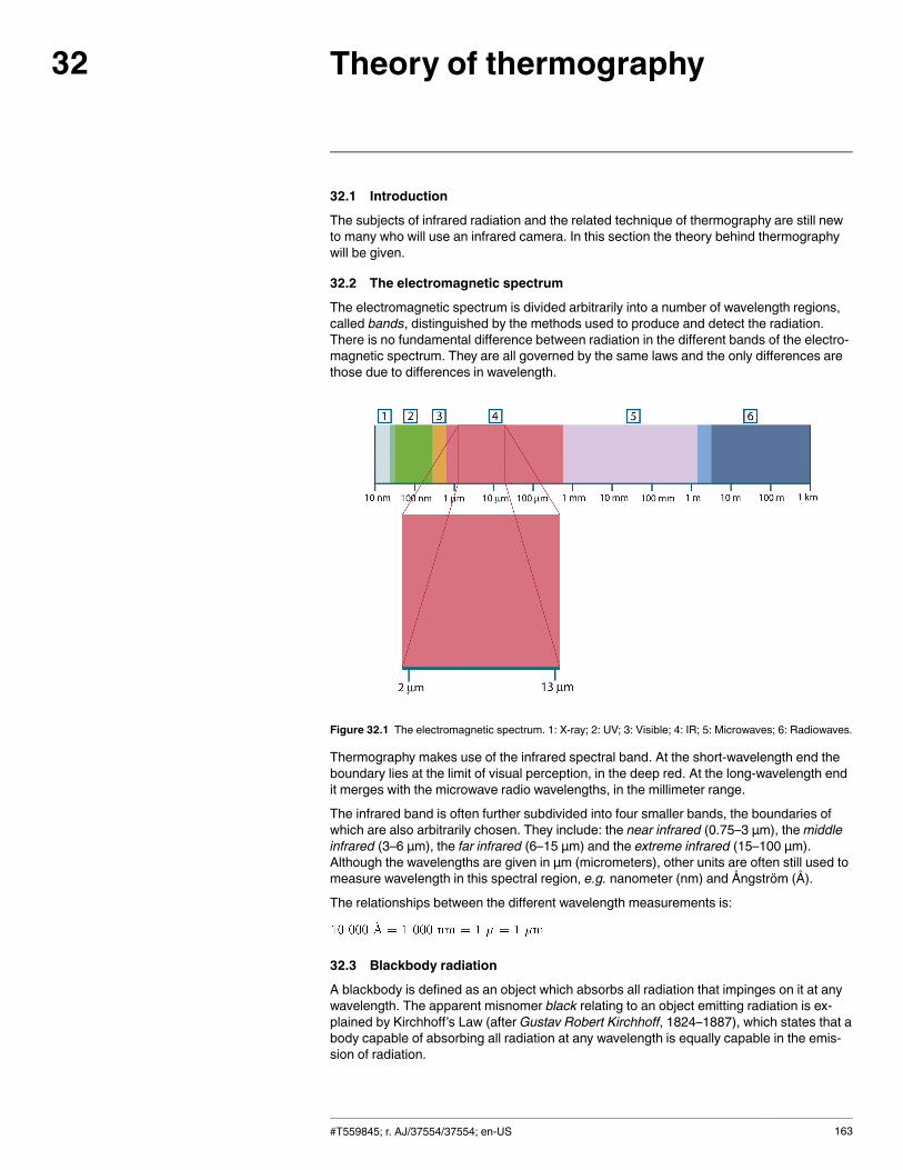
Theory of thermography32
32.1 Introduction
The subjects of infrared radiation and the related technique of thermography are still newto many who will use an infrared camera. In this section the theory behind thermographywill be given.
32.2 The electromagnetic spectrum
The electromagnetic spectrum is divided arbitrarily into a number of wavelength regions,called bands, distinguished by the methods used to produce and detect the radiation.There is no fundamental difference between radiation in the different bands of the electro-magnetic spectrum. They are all governed by the same laws and the only differences arethose due to differences in wavelength.
Figure 32.1 The electromagnetic spectrum. 1: X-ray; 2: UV; 3: Visible; 4: IR; 5: Microwaves; 6: Radiowaves.
Thermography makes use of the infrared spectral band. At the short-wavelength end theboundary lies at the limit of visual perception, in the deep red. At the long-wavelength endit merges with the microwave radio wavelengths, in the millimeter range.
The infrared band is often further subdivided into four smaller bands, the boundaries ofwhich are also arbitrarily chosen. They include: the near infrared (0.75–3 μm), themiddleinfrared (3–6 μm), the far infrared (6–15 μm) and the extreme infrared (15–100 μm).Although the wavelengths are given in μm (micrometers), other units are often still used tomeasure wavelength in this spectral region, e.g. nanometer (nm) and Ångström (Å).
The relationships between the different wavelength measurements is:
32.3 Blackbody radiation
A blackbody is defined as an object which absorbs all radiation that impinges on it at anywavelength. The apparent misnomer black relating to an object emitting radiation is ex-plained by Kirchhoff’s Law (after Gustav Robert Kirchhoff, 1824–1887), which states that abody capable of absorbing all radiation at any wavelength is equally capable in the emis-sion of radiation.
#T559845; r. AJ/37554/37554; en-US 163
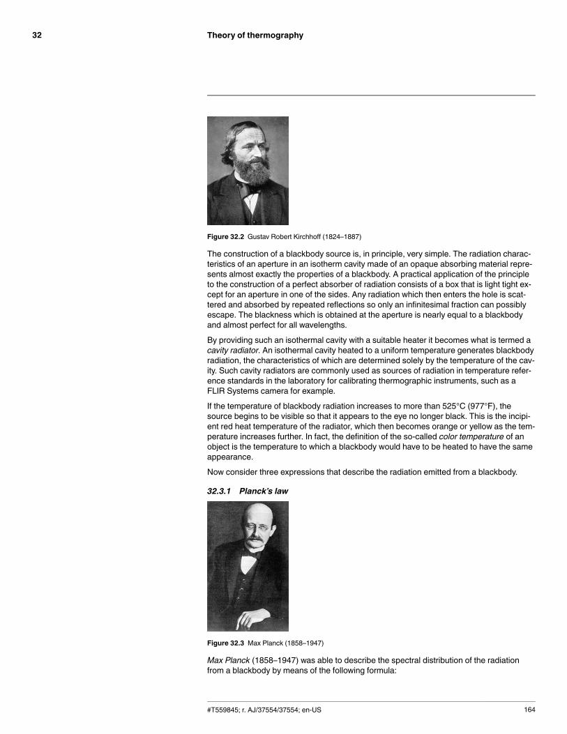
Theory of thermography32
Figure 32.2 Gustav Robert Kirchhoff (1824–1887)
The construction of a blackbody source is, in principle, very simple. The radiation charac-teristics of an aperture in an isotherm cavity made of an opaque absorbing material repre-sents almost exactly the properties of a blackbody. A practical application of the principleto the construction of a perfect absorber of radiation consists of a box that is light tight ex-cept for an aperture in one of the sides. Any radiation which then enters the hole is scat-tered and absorbed by repeated reflections so only an infinitesimal fraction can possiblyescape. The blackness which is obtained at the aperture is nearly equal to a blackbodyand almost perfect for all wavelengths.
By providing such an isothermal cavity with a suitable heater it becomes what is termed acavity radiator. An isothermal cavity heated to a uniform temperature generates blackbodyradiation, the characteristics of which are determined solely by the temperature of the cav-ity. Such cavity radiators are commonly used as sources of radiation in temperature refer-ence standards in the laboratory for calibrating thermographic instruments, such as aFLIR Systems camera for example.
If the temperature of blackbody radiation increases to more than 525°C (977°F), thesource begins to be visible so that it appears to the eye no longer black. This is the incipi-ent red heat temperature of the radiator, which then becomes orange or yellow as the tem-perature increases further. In fact, the definition of the so-called color temperature of anobject is the temperature to which a blackbody would have to be heated to have the sameappearance.
Now consider three expressions that describe the radiation emitted from a blackbody.
32.3.1 Planck’s law
Figure 32.3 Max Planck (1858–1947)
Max Planck (1858–1947) was able to describe the spectral distribution of the radiationfrom a blackbody by means of the following formula:
#T559845; r. AJ/37554/37554; en-US 164
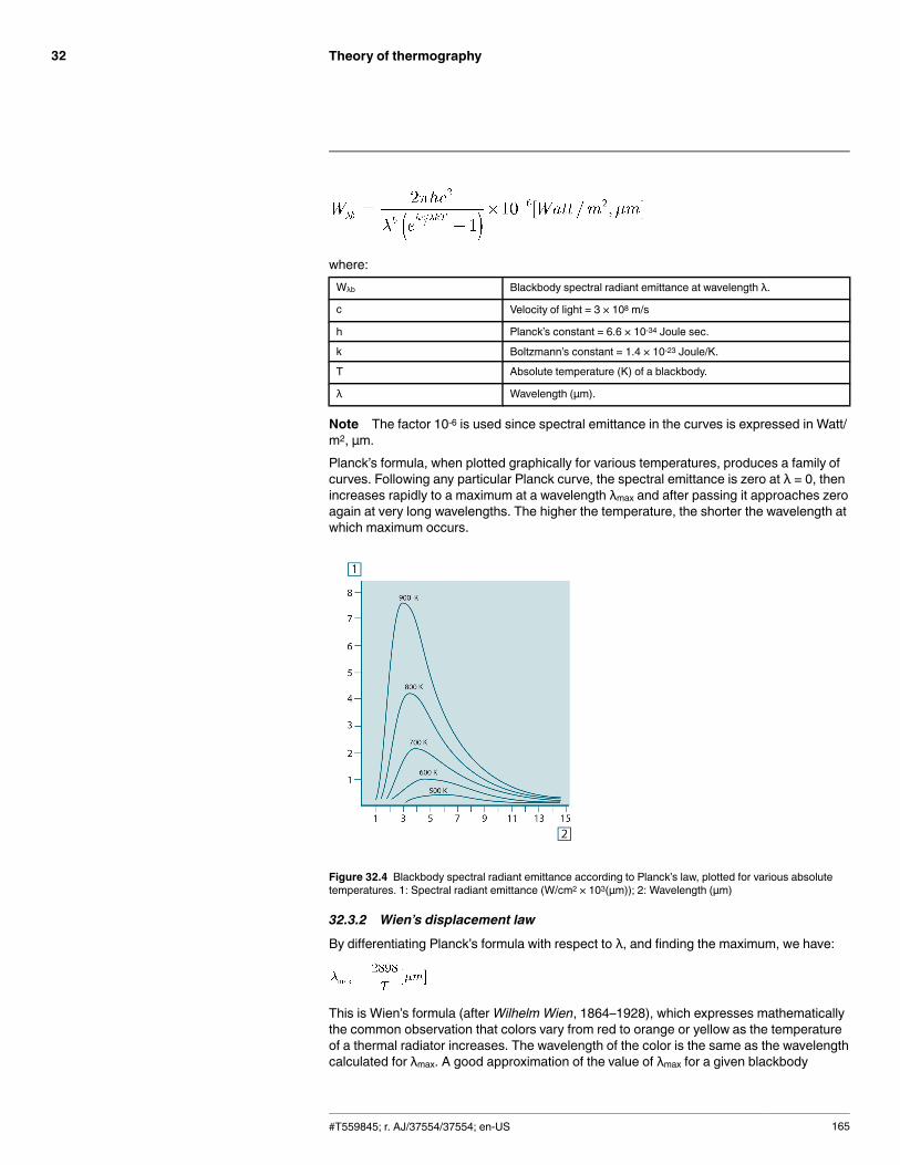
Theory of thermography32
where:Wλb Blackbody spectral radiant emittance at wavelength λ.
c Velocity of light = 3 × 10⁸ m/s
h Planck’s constant = 6.6 × 10⁻³⁴ Joule sec.
k Boltzmann’s constant = 1.4 × 10⁻²³ Joule/K.
T Absolute temperature (K) of a blackbody.
λ Wavelength (μm).
Note The factor 10-6 is used since spectral emittance in the curves is expressed in Watt/m2, μm.Planck’s formula, when plotted graphically for various temperatures, produces a family ofcurves. Following any particular Planck curve, the spectral emittance is zero at λ = 0, thenincreases rapidly to a maximum at a wavelength λmax and after passing it approaches zeroagain at very long wavelengths. The higher the temperature, the shorter the wavelength atwhich maximum occurs.
Figure 32.4 Blackbody spectral radiant emittance according to Planck’s law, plotted for various absolutetemperatures. 1: Spectral radiant emittance (W/cm2 × 103(μm)); 2: Wavelength (μm)
32.3.2 Wien’s displacement law
By differentiating Planck’s formula with respect to λ, and finding the maximum, we have:
This is Wien’s formula (afterWilhelm Wien, 1864–1928), which expresses mathematicallythe common observation that colors vary from red to orange or yellow as the temperatureof a thermal radiator increases. The wavelength of the color is the same as the wavelengthcalculated for λmax. A good approximation of the value of λmax for a given blackbody
#T559845; r. AJ/37554/37554; en-US 165
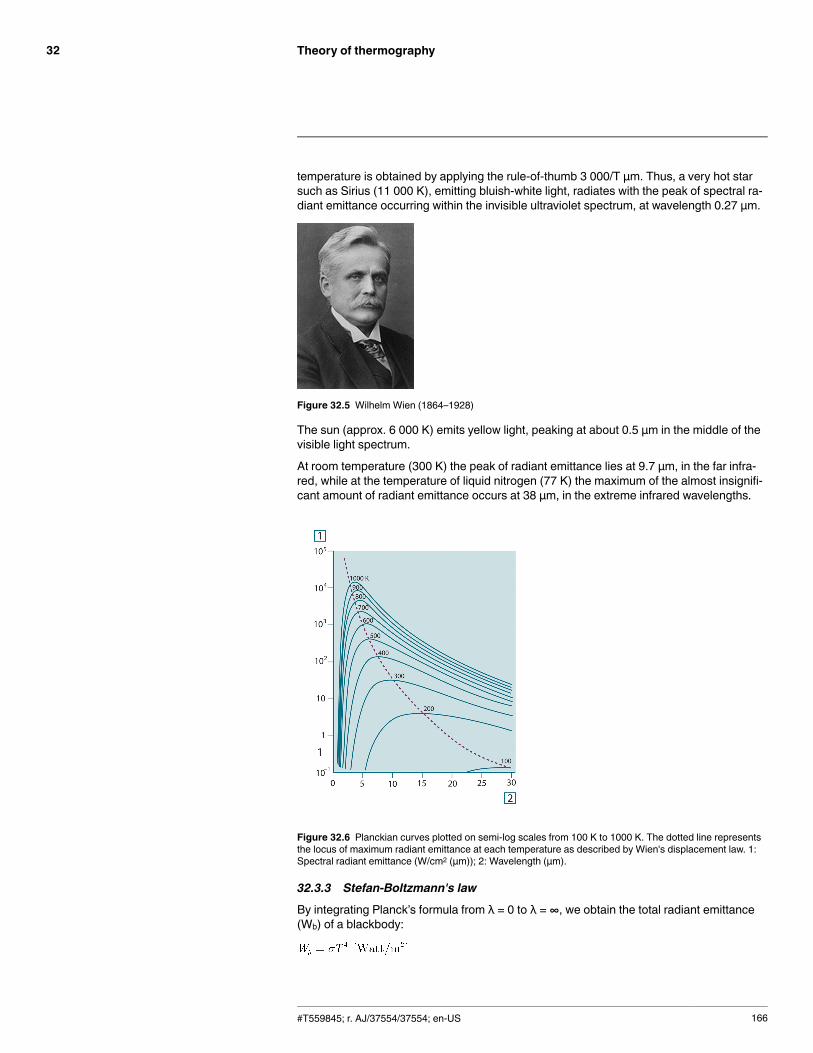
Theory of thermography32
temperature is obtained by applying the rule-of-thumb 3 000/T μm. Thus, a very hot starsuch as Sirius (11 000 K), emitting bluish-white light, radiates with the peak of spectral ra-diant emittance occurring within the invisible ultraviolet spectrum, at wavelength 0.27 μm.
Figure 32.5 Wilhelm Wien (1864–1928)
The sun (approx. 6 000 K) emits yellow light, peaking at about 0.5 μm in the middle of thevisible light spectrum.
At room temperature (300 K) the peak of radiant emittance lies at 9.7 μm, in the far infra-red, while at the temperature of liquid nitrogen (77 K) the maximum of the almost insignifi-cant amount of radiant emittance occurs at 38 μm, in the extreme infrared wavelengths.
Figure 32.6 Planckian curves plotted on semi-log scales from 100 K to 1000 K. The dotted line representsthe locus of maximum radiant emittance at each temperature as described by Wien's displacement law. 1:Spectral radiant emittance (W/cm2 (μm)); 2: Wavelength (μm).
32.3.3 Stefan-Boltzmann's law
By integrating Planck’s formula from λ = 0 to λ = ∞, we obtain the total radiant emittance(Wb) of a blackbody:
#T559845; r. AJ/37554/37554; en-US 166

Theory of thermography32
This is the Stefan-Boltzmann formula (after Josef Stefan, 1835–1893, and Ludwig Boltz-mann, 1844–1906), which states that the total emissive power of a blackbody is propor-tional to the fourth power of its absolute temperature. Graphically, Wb represents the areabelow the Planck curve for a particular temperature. It can be shown that the radiant emit-tance in the interval λ = 0 to λmax is only 25% of the total, which represents about theamount of the sun’s radiation which lies inside the visible light spectrum.
Figure 32.7 Josef Stefan (1835–1893), and Ludwig Boltzmann (1844–1906)
Using the Stefan-Boltzmann formula to calculate the power radiated by the human body,at a temperature of 300 K and an external surface area of approx. 2 m2, we obtain 1 kW.This power loss could not be sustained if it were not for the compensating absorption of ra-diation from surrounding surfaces, at room temperatures which do not vary too drasticallyfrom the temperature of the body – or, of course, the addition of clothing.
32.3.4 Non-blackbody emitters
So far, only blackbody radiators and blackbody radiation have been discussed. However,real objects almost never comply with these laws over an extended wavelength region –although they may approach the blackbody behavior in certain spectral intervals. For ex-ample, a certain type of white paint may appear perfectly white in the visible light spec-trum, but becomes distinctly gray at about 2 μm, and beyond 3 μm it is almost black.
There are three processes which can occur that prevent a real object from acting like ablackbody: a fraction of the incident radiation α may be absorbed, a fraction ρ may be re-flected, and a fraction τ may be transmitted. Since all of these factors are more or lesswavelength dependent, the subscript λ is used to imply the spectral dependence of theirdefinitions. Thus:
• The spectral absorptance αλ= the ratio of the spectral radiant power absorbed by an ob-ject to that incident upon it.
• The spectral reflectance ρλ = the ratio of the spectral radiant power reflected by an ob-ject to that incident upon it.
• The spectral transmittance τλ = the ratio of the spectral radiant power transmittedthrough an object to that incident upon it.
The sum of these three factors must always add up to the whole at any wavelength, so wehave the relation:
For opaque materials τλ = 0 and the relation simplifies to:
Another factor, called the emissivity, is required to describe the fraction ε of the radiantemittance of a blackbody produced by an object at a specific temperature. Thus, we havethe definition:
#T559845; r. AJ/37554/37554; en-US 167
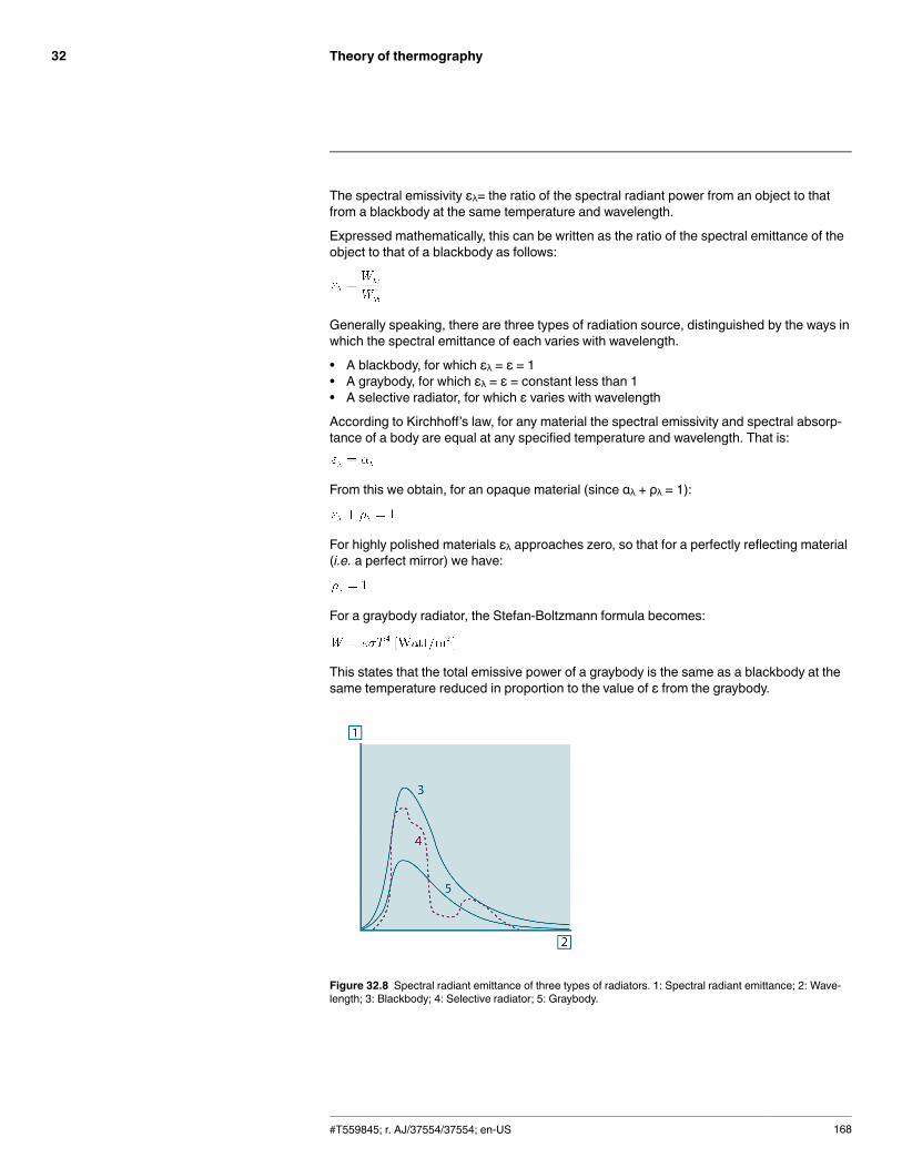
Theory of thermography32
The spectral emissivity ελ= the ratio of the spectral radiant power from an object to thatfrom a blackbody at the same temperature and wavelength.
Expressed mathematically, this can be written as the ratio of the spectral emittance of theobject to that of a blackbody as follows:
Generally speaking, there are three types of radiation source, distinguished by the ways inwhich the spectral emittance of each varies with wavelength.
• A blackbody, for which ελ = ε = 1• A graybody, for which ελ = ε = constant less than 1• A selective radiator, for which ε varies with wavelength
According to Kirchhoff’s law, for any material the spectral emissivity and spectral absorp-tance of a body are equal at any specified temperature and wavelength. That is:
From this we obtain, for an opaque material (since αλ + ρλ = 1):
For highly polished materials ελ approaches zero, so that for a perfectly reflecting material(i.e. a perfect mirror) we have:
For a graybody radiator, the Stefan-Boltzmann formula becomes:
This states that the total emissive power of a graybody is the same as a blackbody at thesame temperature reduced in proportion to the value of ε from the graybody.
Figure 32.8 Spectral radiant emittance of three types of radiators. 1: Spectral radiant emittance; 2: Wave-length; 3: Blackbody; 4: Selective radiator; 5: Graybody.
#T559845; r. AJ/37554/37554; en-US 168
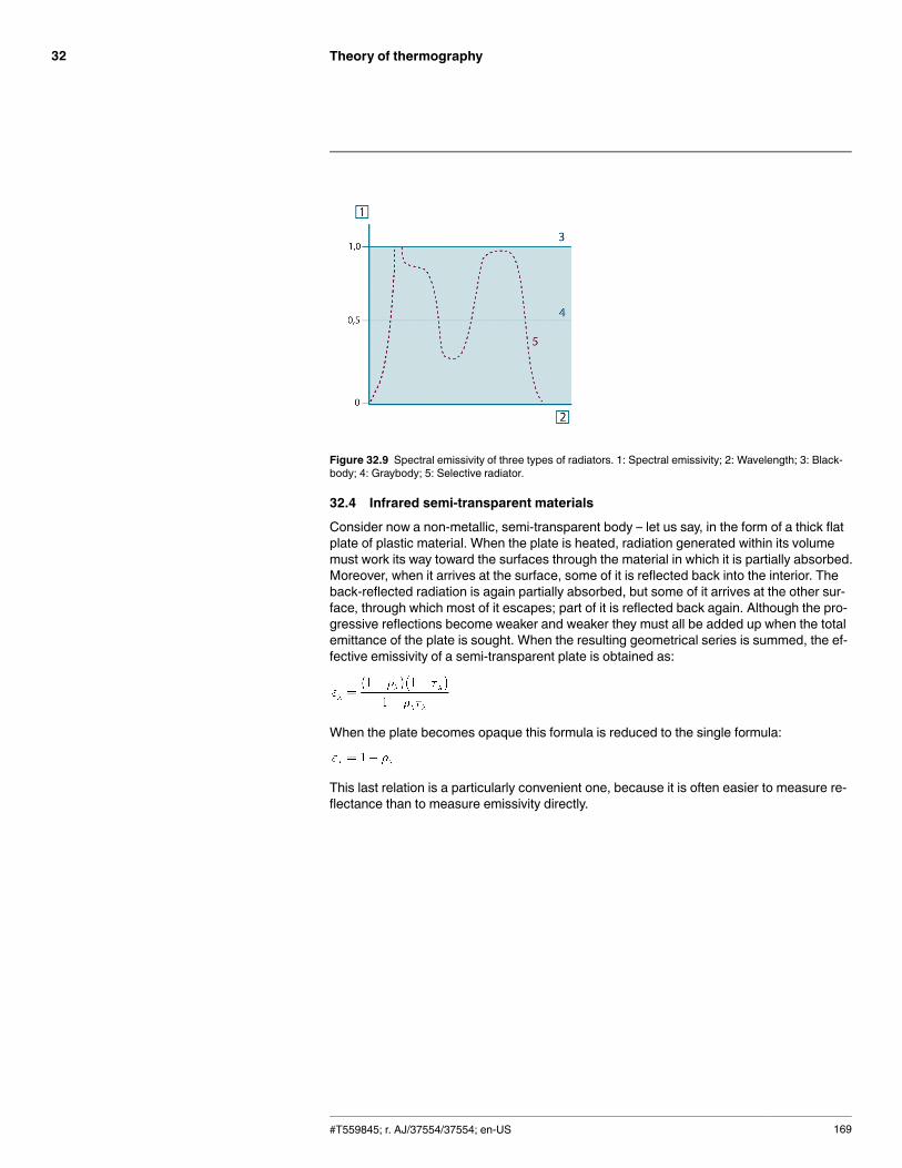
Theory of thermography32
Figure 32.9 Spectral emissivity of three types of radiators. 1: Spectral emissivity; 2: Wavelength; 3: Black-body; 4: Graybody; 5: Selective radiator.
32.4 Infrared semi-transparent materials
Consider now a non-metallic, semi-transparent body – let us say, in the form of a thick flatplate of plastic material. When the plate is heated, radiation generated within its volumemust work its way toward the surfaces through the material in which it is partially absorbed.Moreover, when it arrives at the surface, some of it is reflected back into the interior. Theback-reflected radiation is again partially absorbed, but some of it arrives at the other sur-face, through which most of it escapes; part of it is reflected back again. Although the pro-gressive reflections become weaker and weaker they must all be added up when the totalemittance of the plate is sought. When the resulting geometrical series is summed, the ef-fective emissivity of a semi-transparent plate is obtained as:
When the plate becomes opaque this formula is reduced to the single formula:
This last relation is a particularly convenient one, because it is often easier to measure re-flectance than to measure emissivity directly.
#T559845; r. AJ/37554/37554; en-US 169
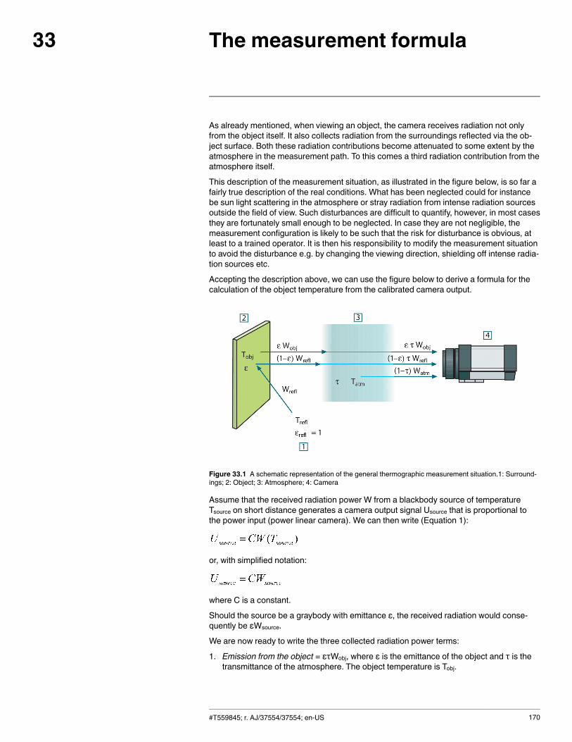
The measurement formula33
As already mentioned, when viewing an object, the camera receives radiation not onlyfrom the object itself. It also collects radiation from the surroundings reflected via the ob-ject surface. Both these radiation contributions become attenuated to some extent by theatmosphere in the measurement path. To this comes a third radiation contribution from theatmosphere itself.
This description of the measurement situation, as illustrated in the figure below, is so far afairly true description of the real conditions. What has been neglected could for instancebe sun light scattering in the atmosphere or stray radiation from intense radiation sourcesoutside the field of view. Such disturbances are difficult to quantify, however, in most casesthey are fortunately small enough to be neglected. In case they are not negligible, themeasurement configuration is likely to be such that the risk for disturbance is obvious, atleast to a trained operator. It is then his responsibility to modify the measurement situationto avoid the disturbance e.g. by changing the viewing direction, shielding off intense radia-tion sources etc.
Accepting the description above, we can use the figure below to derive a formula for thecalculation of the object temperature from the calibrated camera output.
Figure 33.1 A schematic representation of the general thermographic measurement situation.1: Surround-ings; 2: Object; 3: Atmosphere; 4: Camera
Assume that the received radiation power W from a blackbody source of temperatureTsource on short distance generates a camera output signal Usource that is proportional tothe power input (power linear camera). We can then write (Equation 1):
or, with simplified notation:
where C is a constant.
Should the source be a graybody with emittance ε, the received radiation would conse-quently be εWsource.
We are now ready to write the three collected radiation power terms:
1. Emission from the object = ετWobj, where ε is the emittance of the object and τ is thetransmittance of the atmosphere. The object temperature is Tobj.
#T559845; r. AJ/37554/37554; en-US 170
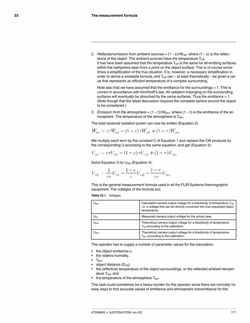
The measurement formula33
2. Reflected emission from ambient sources = (1 – ε)τWrefl, where (1 – ε) is the reflec-tance of the object. The ambient sources have the temperature Trefl.It has here been assumed that the temperature Trefl is the same for all emitting surfaceswithin the halfsphere seen from a point on the object surface. This is of course some-times a simplification of the true situation. It is, however, a necessary simplification inorder to derive a workable formula, and Trefl can – at least theoretically – be given a val-ue that represents an efficient temperature of a complex surrounding.
Note also that we have assumed that the emittance for the surroundings = 1. This iscorrect in accordance with Kirchhoff’s law: All radiation impinging on the surroundingsurfaces will eventually be absorbed by the same surfaces. Thus the emittance = 1.(Note though that the latest discussion requires the complete sphere around the objectto be considered.)
3. Emission from the atmosphere = (1 – τ)τWatm, where (1 – τ) is the emittance of the at-mosphere. The temperature of the atmosphere is Tatm.
The total received radiation power can now be written (Equation 2):
We multiply each term by the constant C of Equation 1 and replace the CW products bythe corresponding U according to the same equation, and get (Equation 3):
Solve Equation 3 for Uobj (Equation 4):
This is the general measurement formula used in all the FLIR Systems thermographicequipment. The voltages of the formula are:Table 33.1 Voltages
Uobj Calculated camera output voltage for a blackbody of temperature Tobji.e. a voltage that can be directly converted into true requested objecttemperature.
Utot Measured camera output voltage for the actual case.
Urefl Theoretical camera output voltage for a blackbody of temperatureTrefl according to the calibration.
Uatm Theoretical camera output voltage for a blackbody of temperatureTatm according to the calibration.
The operator has to supply a number of parameter values for the calculation:
• the object emittance ε,• the relative humidity,• Tatm• object distance (Dobj)• the (effective) temperature of the object surroundings, or the reflected ambient temper-ature Trefl, and
• the temperature of the atmosphere TatmThis task could sometimes be a heavy burden for the operator since there are normally noeasy ways to find accurate values of emittance and atmospheric transmittance for the
#T559845; r. AJ/37554/37554; en-US 171
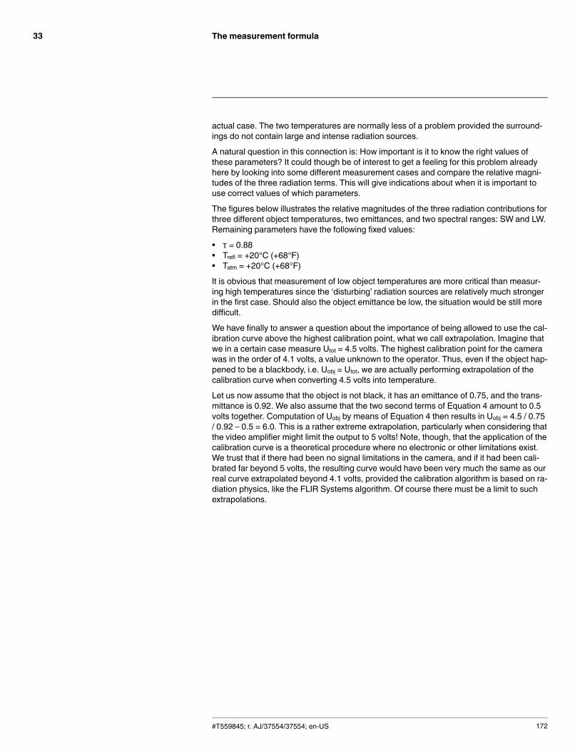
The measurement formula33
actual case. The two temperatures are normally less of a problem provided the surround-ings do not contain large and intense radiation sources.
A natural question in this connection is: How important is it to know the right values ofthese parameters? It could though be of interest to get a feeling for this problem alreadyhere by looking into some different measurement cases and compare the relative magni-tudes of the three radiation terms. This will give indications about when it is important touse correct values of which parameters.
The figures below illustrates the relative magnitudes of the three radiation contributions forthree different object temperatures, two emittances, and two spectral ranges: SW and LW.Remaining parameters have the following fixed values:
• τ = 0.88• Trefl = +20°C (+68°F)• Tatm = +20°C (+68°F)
It is obvious that measurement of low object temperatures are more critical than measur-ing high temperatures since the ‘disturbing’ radiation sources are relatively much strongerin the first case. Should also the object emittance be low, the situation would be still moredifficult.
We have finally to answer a question about the importance of being allowed to use the cal-ibration curve above the highest calibration point, what we call extrapolation. Imagine thatwe in a certain case measure Utot = 4.5 volts. The highest calibration point for the camerawas in the order of 4.1 volts, a value unknown to the operator. Thus, even if the object hap-pened to be a blackbody, i.e. Uobj = Utot, we are actually performing extrapolation of thecalibration curve when converting 4.5 volts into temperature.
Let us now assume that the object is not black, it has an emittance of 0.75, and the trans-mittance is 0.92. We also assume that the two second terms of Equation 4 amount to 0.5volts together. Computation of Uobj by means of Equation 4 then results in Uobj = 4.5 / 0.75/ 0.92 – 0.5 = 6.0. This is a rather extreme extrapolation, particularly when considering thatthe video amplifier might limit the output to 5 volts! Note, though, that the application of thecalibration curve is a theoretical procedure where no electronic or other limitations exist.We trust that if there had been no signal limitations in the camera, and if it had been cali-brated far beyond 5 volts, the resulting curve would have been very much the same as ourreal curve extrapolated beyond 4.1 volts, provided the calibration algorithm is based on ra-diation physics, like the FLIR Systems algorithm. Of course there must be a limit to suchextrapolations.
#T559845; r. AJ/37554/37554; en-US 172
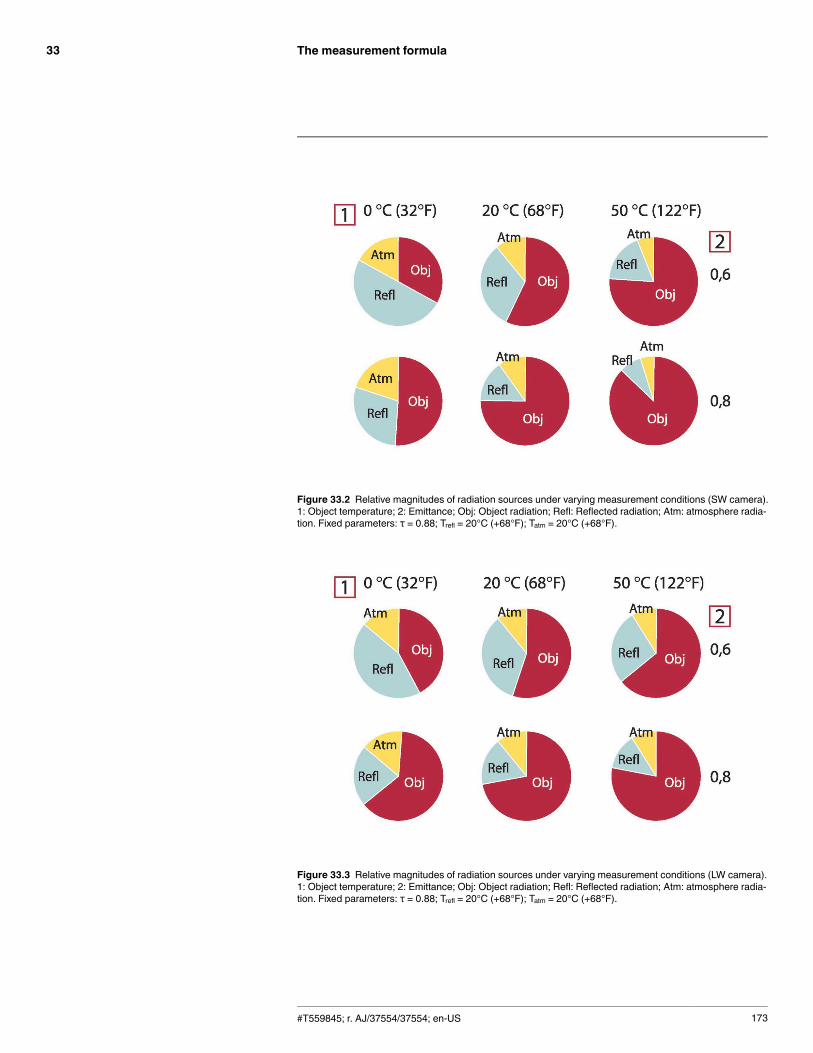
The measurement formula33
Figure 33.2 Relative magnitudes of radiation sources under varying measurement conditions (SW camera).1: Object temperature; 2: Emittance; Obj: Object radiation; Refl: Reflected radiation; Atm: atmosphere radia-tion. Fixed parameters: τ = 0.88; Trefl = 20°C (+68°F); Tatm = 20°C (+68°F).
Figure 33.3 Relative magnitudes of radiation sources under varying measurement conditions (LW camera).1: Object temperature; 2: Emittance; Obj: Object radiation; Refl: Reflected radiation; Atm: atmosphere radia-tion. Fixed parameters: τ = 0.88; Trefl = 20°C (+68°F); Tatm = 20°C (+68°F).
#T559845; r. AJ/37554/37554; en-US 173
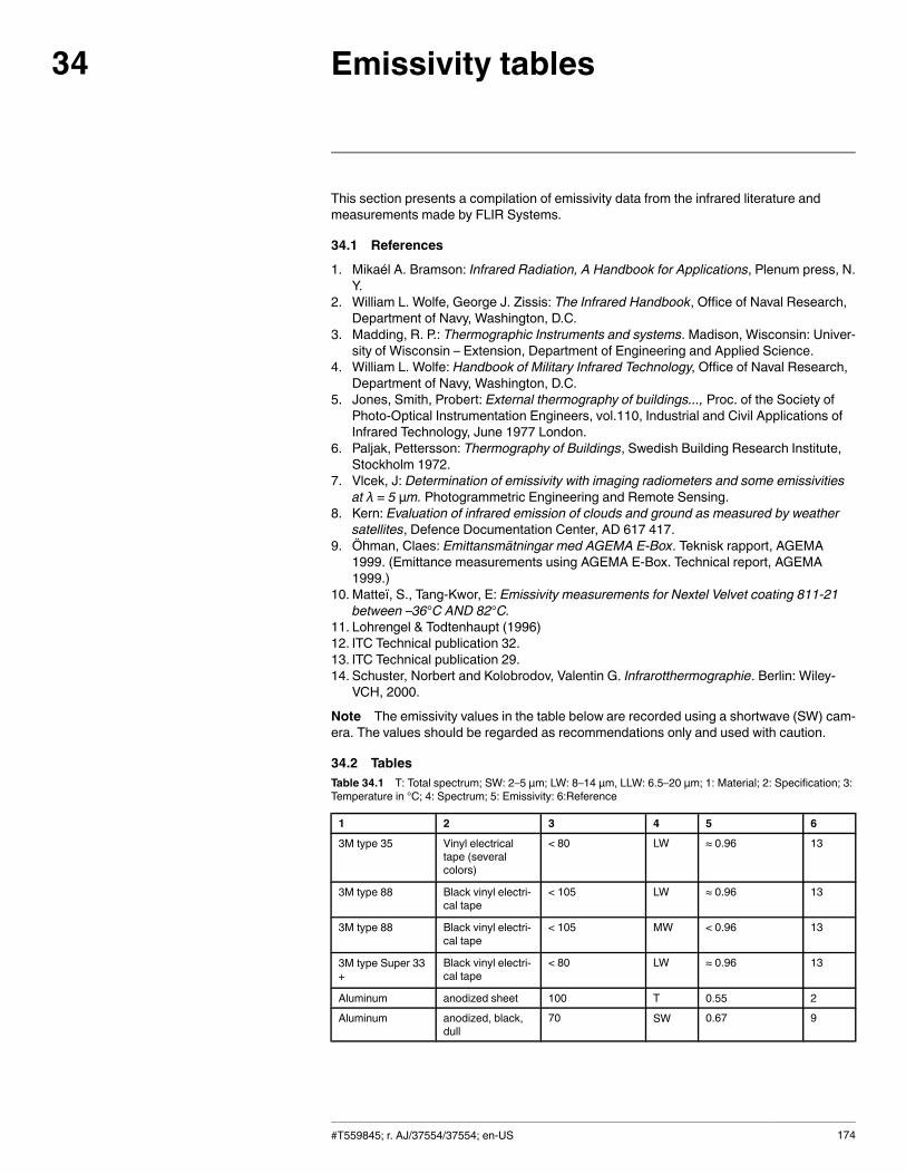
Emissivity tables34
This section presents a compilation of emissivity data from the infrared literature andmeasurements made by FLIR Systems.
34.1 References
1. Mikaél A. Bramson: Infrared Radiation, A Handbook for Applications, Plenum press, N.Y.
2. William L. Wolfe, George J. Zissis: The Infrared Handbook, Office of Naval Research,Department of Navy, Washington, D.C.
3. Madding, R. P.: Thermographic Instruments and systems. Madison, Wisconsin: Univer-sity of Wisconsin – Extension, Department of Engineering and Applied Science.
4. William L. Wolfe: Handbook of Military Infrared Technology, Office of Naval Research,Department of Navy, Washington, D.C.
5. Jones, Smith, Probert: External thermography of buildings..., Proc. of the Society ofPhoto-Optical Instrumentation Engineers, vol.110, Industrial and Civil Applications ofInfrared Technology, June 1977 London.
6. Paljak, Pettersson: Thermography of Buildings, Swedish Building Research Institute,Stockholm 1972.
7. Vlcek, J: Determination of emissivity with imaging radiometers and some emissivitiesat λ = 5 µm. Photogrammetric Engineering and Remote Sensing.
8. Kern: Evaluation of infrared emission of clouds and ground as measured by weathersatellites, Defence Documentation Center, AD 617 417.
9. Öhman, Claes: Emittansmätningar med AGEMA E-Box. Teknisk rapport, AGEMA1999. (Emittance measurements using AGEMA E-Box. Technical report, AGEMA1999.)
10. Matteï, S., Tang-Kwor, E: Emissivity measurements for Nextel Velvet coating 811-21between –36°C AND 82°C.
11. Lohrengel & Todtenhaupt (1996)12. ITC Technical publication 32.13. ITC Technical publication 29.14. Schuster, Norbert and Kolobrodov, Valentin G. Infrarotthermographie. Berlin: Wiley-
VCH, 2000.
Note The emissivity values in the table below are recorded using a shortwave (SW) cam-era. The values should be regarded as recommendations only and used with caution.
34.2 TablesTable 34.1 T: Total spectrum; SW: 2–5 µm; LW: 8–14 µm, LLW: 6.5–20 µm; 1: Material; 2: Specification; 3:Temperature in °C; 4: Spectrum; 5: Emissivity: 6:Reference
1 2 3 4 5 6
3M type 35 Vinyl electricaltape (severalcolors)
< 80 LW ≈ 0.96 13
3M type 88 Black vinyl electri-cal tape
< 105 LW ≈ 0.96 13
3M type 88 Black vinyl electri-cal tape
< 105 MW < 0.96 13
3M type Super 33+
Black vinyl electri-cal tape
< 80 LW ≈ 0.96 13
Aluminum anodized sheet 100 T 0.55 2
Aluminum anodized, black,dull
70 SW 0.67 9
#T559845; r. AJ/37554/37554; en-US 174
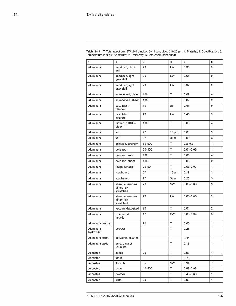
Emissivity tables34
Table 34.1 T: Total spectrum; SW: 2–5 µm; LW: 8–14 µm, LLW: 6.5–20 µm; 1: Material; 2: Specification; 3:Temperature in °C; 4: Spectrum; 5: Emissivity: 6:Reference (continued)
1 2 3 4 5 6
Aluminum anodized, black,dull
70 LW 0.95 9
Aluminum anodized, lightgray, dull
70 SW 0.61 9
Aluminum anodized, lightgray, dull
70 LW 0.97 9
Aluminum as received, plate 100 T 0.09 4
Aluminum as received, sheet 100 T 0.09 2
Aluminum cast, blastcleaned
70 SW 0.47 9
Aluminum cast, blastcleaned
70 LW 0.46 9
Aluminum dipped in HNO3,plate
100 T 0.05 4
Aluminum foil 27 10 µm 0.04 3
Aluminum foil 27 3 µm 0.09 3
Aluminum oxidized, strongly 50–500 T 0.2–0.3 1
Aluminum polished 50–100 T 0.04–0.06 1
Aluminum polished plate 100 T 0.05 4
Aluminum polished, sheet 100 T 0.05 2
Aluminum rough surface 20–50 T 0.06–0.07 1
Aluminum roughened 27 10 µm 0.18 3
Aluminum roughened 27 3 µm 0.28 3
Aluminum sheet, 4 samplesdifferentlyscratched
70 SW 0.05–0.08 9
Aluminum sheet, 4 samplesdifferentlyscratched
70 LW 0.03–0.06 9
Aluminum vacuum deposited 20 T 0.04 2
Aluminum weathered,heavily
17 SW 0.83–0.94 5
Aluminum bronze 20 T 0.60 1
Aluminumhydroxide
powder T 0.28 1
Aluminum oxide activated, powder T 0.46 1
Aluminum oxide pure, powder(alumina)
T 0.16 1
Asbestos board 20 T 0.96 1
Asbestos fabric T 0.78 1
Asbestos floor tile 35 SW 0.94 7
Asbestos paper 40–400 T 0.93–0.95 1
Asbestos powder T 0.40–0.60 1
Asbestos slate 20 T 0.96 1
#T559845; r. AJ/37554/37554; en-US 175
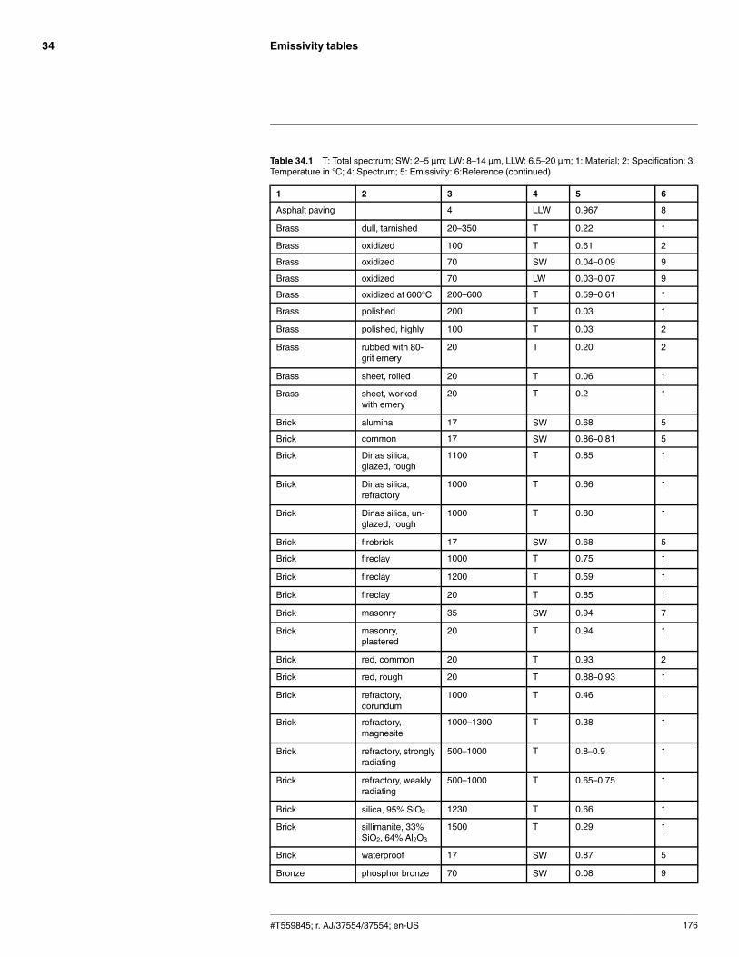
Emissivity tables34
Table 34.1 T: Total spectrum; SW: 2–5 µm; LW: 8–14 µm, LLW: 6.5–20 µm; 1: Material; 2: Specification; 3:Temperature in °C; 4: Spectrum; 5: Emissivity: 6:Reference (continued)
1 2 3 4 5 6
Asphalt paving 4 LLW 0.967 8
Brass dull, tarnished 20–350 T 0.22 1
Brass oxidized 100 T 0.61 2
Brass oxidized 70 SW 0.04–0.09 9
Brass oxidized 70 LW 0.03–0.07 9
Brass oxidized at 600°C 200–600 T 0.59–0.61 1
Brass polished 200 T 0.03 1
Brass polished, highly 100 T 0.03 2
Brass rubbed with 80-grit emery
20 T 0.20 2
Brass sheet, rolled 20 T 0.06 1
Brass sheet, workedwith emery
20 T 0.2 1
Brick alumina 17 SW 0.68 5
Brick common 17 SW 0.86–0.81 5
Brick Dinas silica,glazed, rough
1100 T 0.85 1
Brick Dinas silica,refractory
1000 T 0.66 1
Brick Dinas silica, un-glazed, rough
1000 T 0.80 1
Brick firebrick 17 SW 0.68 5
Brick fireclay 1000 T 0.75 1
Brick fireclay 1200 T 0.59 1
Brick fireclay 20 T 0.85 1
Brick masonry 35 SW 0.94 7
Brick masonry,plastered
20 T 0.94 1
Brick red, common 20 T 0.93 2
Brick red, rough 20 T 0.88–0.93 1
Brick refractory,corundum
1000 T 0.46 1
Brick refractory,magnesite
1000–1300 T 0.38 1
Brick refractory, stronglyradiating
500–1000 T 0.8–0.9 1
Brick refractory, weaklyradiating
500–1000 T 0.65–0.75 1
Brick silica, 95% SiO2 1230 T 0.66 1
Brick sillimanite, 33%SiO2, 64% Al2O3
1500 T 0.29 1
Brick waterproof 17 SW 0.87 5
Bronze phosphor bronze 70 SW 0.08 9
#T559845; r. AJ/37554/37554; en-US 176
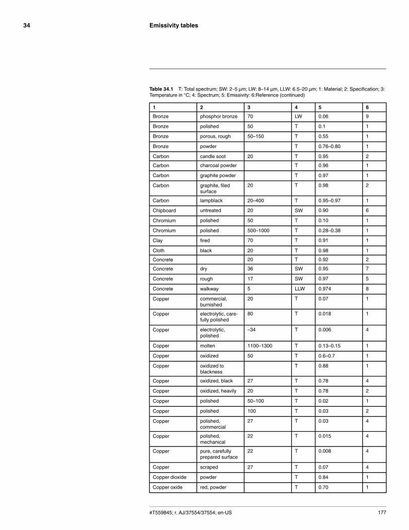
Emissivity tables34
Table 34.1 T: Total spectrum; SW: 2–5 µm; LW: 8–14 µm, LLW: 6.5–20 µm; 1: Material; 2: Specification; 3:Temperature in °C; 4: Spectrum; 5: Emissivity: 6:Reference (continued)
1 2 3 4 5 6
Bronze phosphor bronze 70 LW 0.06 9
Bronze polished 50 T 0.1 1
Bronze porous, rough 50–150 T 0.55 1
Bronze powder T 0.76–0.80 1
Carbon candle soot 20 T 0.95 2
Carbon charcoal powder T 0.96 1
Carbon graphite powder T 0.97 1
Carbon graphite, filedsurface
20 T 0.98 2
Carbon lampblack 20–400 T 0.95–0.97 1
Chipboard untreated 20 SW 0.90 6
Chromium polished 50 T 0.10 1
Chromium polished 500–1000 T 0.28–0.38 1
Clay fired 70 T 0.91 1
Cloth black 20 T 0.98 1
Concrete 20 T 0.92 2
Concrete dry 36 SW 0.95 7
Concrete rough 17 SW 0.97 5
Concrete walkway 5 LLW 0.974 8
Copper commercial,burnished
20 T 0.07 1
Copper electrolytic, care-fully polished
80 T 0.018 1
Copper electrolytic,polished
–34 T 0.006 4
Copper molten 1100–1300 T 0.13–0.15 1
Copper oxidized 50 T 0.6–0.7 1
Copper oxidized toblackness
T 0.88 1
Copper oxidized, black 27 T 0.78 4
Copper oxidized, heavily 20 T 0.78 2
Copper polished 50–100 T 0.02 1
Copper polished 100 T 0.03 2
Copper polished,commercial
27 T 0.03 4
Copper polished,mechanical
22 T 0.015 4
Copper pure, carefullyprepared surface
22 T 0.008 4
Copper scraped 27 T 0.07 4
Copper dioxide powder T 0.84 1
Copper oxide red, powder T 0.70 1
#T559845; r. AJ/37554/37554; en-US 177
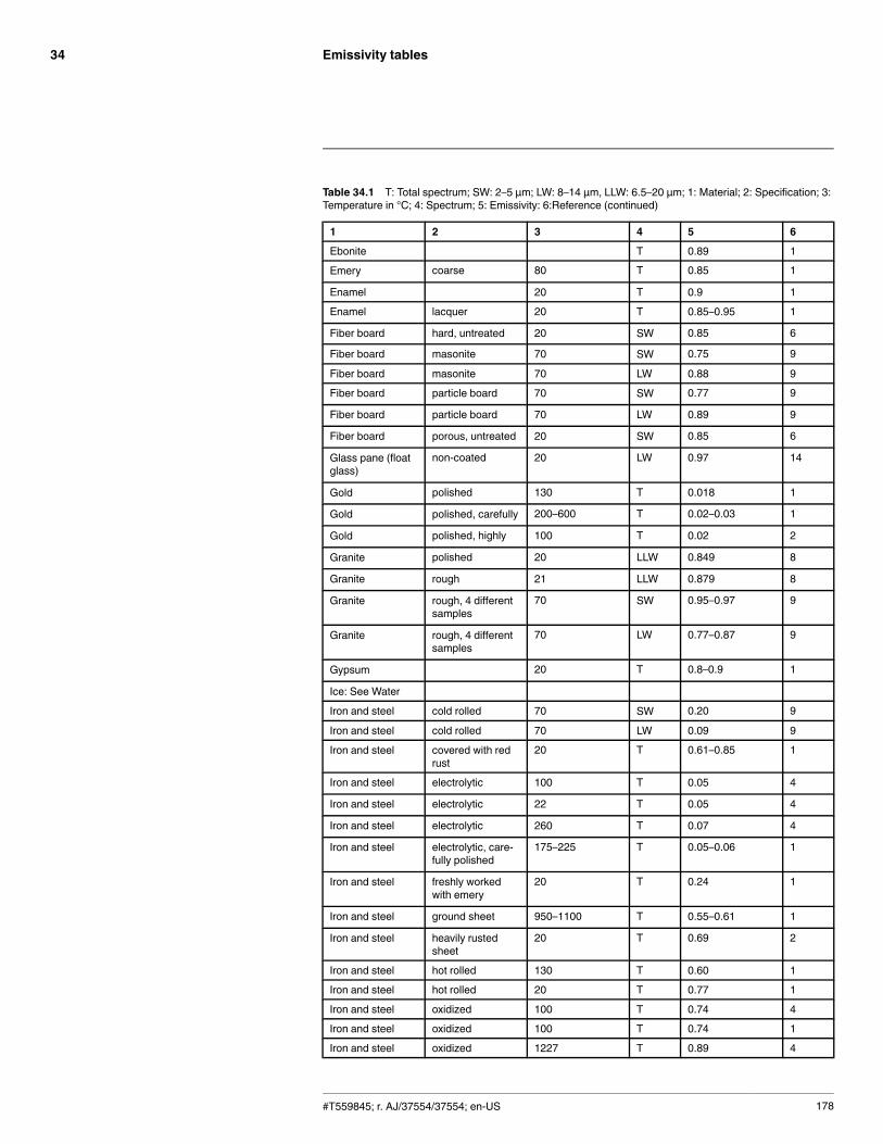
Emissivity tables34
Table 34.1 T: Total spectrum; SW: 2–5 µm; LW: 8–14 µm, LLW: 6.5–20 µm; 1: Material; 2: Specification; 3:Temperature in °C; 4: Spectrum; 5: Emissivity: 6:Reference (continued)
1 2 3 4 5 6
Ebonite T 0.89 1
Emery coarse 80 T 0.85 1
Enamel 20 T 0.9 1
Enamel lacquer 20 T 0.85–0.95 1
Fiber board hard, untreated 20 SW 0.85 6
Fiber board masonite 70 SW 0.75 9
Fiber board masonite 70 LW 0.88 9
Fiber board particle board 70 SW 0.77 9
Fiber board particle board 70 LW 0.89 9
Fiber board porous, untreated 20 SW 0.85 6
Glass pane (floatglass)
non-coated 20 LW 0.97 14
Gold polished 130 T 0.018 1
Gold polished, carefully 200–600 T 0.02–0.03 1
Gold polished, highly 100 T 0.02 2
Granite polished 20 LLW 0.849 8
Granite rough 21 LLW 0.879 8
Granite rough, 4 differentsamples
70 SW 0.95–0.97 9
Granite rough, 4 differentsamples
70 LW 0.77–0.87 9
Gypsum 20 T 0.8–0.9 1
Ice: See Water
Iron and steel cold rolled 70 SW 0.20 9
Iron and steel cold rolled 70 LW 0.09 9
Iron and steel covered with redrust
20 T 0.61–0.85 1
Iron and steel electrolytic 100 T 0.05 4
Iron and steel electrolytic 22 T 0.05 4
Iron and steel electrolytic 260 T 0.07 4
Iron and steel electrolytic, care-fully polished
175–225 T 0.05–0.06 1
Iron and steel freshly workedwith emery
20 T 0.24 1
Iron and steel ground sheet 950–1100 T 0.55–0.61 1
Iron and steel heavily rustedsheet
20 T 0.69 2
Iron and steel hot rolled 130 T 0.60 1
Iron and steel hot rolled 20 T 0.77 1
Iron and steel oxidized 100 T 0.74 4
Iron and steel oxidized 100 T 0.74 1
Iron and steel oxidized 1227 T 0.89 4
#T559845; r. AJ/37554/37554; en-US 178
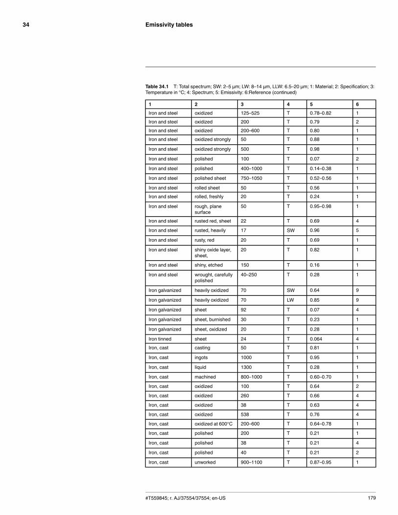
Emissivity tables34
Table 34.1 T: Total spectrum; SW: 2–5 µm; LW: 8–14 µm, LLW: 6.5–20 µm; 1: Material; 2: Specification; 3:Temperature in °C; 4: Spectrum; 5: Emissivity: 6:Reference (continued)
1 2 3 4 5 6
Iron and steel oxidized 125–525 T 0.78–0.82 1
Iron and steel oxidized 200 T 0.79 2
Iron and steel oxidized 200–600 T 0.80 1
Iron and steel oxidized strongly 50 T 0.88 1
Iron and steel oxidized strongly 500 T 0.98 1
Iron and steel polished 100 T 0.07 2
Iron and steel polished 400–1000 T 0.14–0.38 1
Iron and steel polished sheet 750–1050 T 0.52–0.56 1
Iron and steel rolled sheet 50 T 0.56 1
Iron and steel rolled, freshly 20 T 0.24 1
Iron and steel rough, planesurface
50 T 0.95–0.98 1
Iron and steel rusted red, sheet 22 T 0.69 4
Iron and steel rusted, heavily 17 SW 0.96 5
Iron and steel rusty, red 20 T 0.69 1
Iron and steel shiny oxide layer,sheet,
20 T 0.82 1
Iron and steel shiny, etched 150 T 0.16 1
Iron and steel wrought, carefullypolished
40–250 T 0.28 1
Iron galvanized heavily oxidized 70 SW 0.64 9
Iron galvanized heavily oxidized 70 LW 0.85 9
Iron galvanized sheet 92 T 0.07 4
Iron galvanized sheet, burnished 30 T 0.23 1
Iron galvanized sheet, oxidized 20 T 0.28 1
Iron tinned sheet 24 T 0.064 4
Iron, cast casting 50 T 0.81 1
Iron, cast ingots 1000 T 0.95 1
Iron, cast liquid 1300 T 0.28 1
Iron, cast machined 800–1000 T 0.60–0.70 1
Iron, cast oxidized 100 T 0.64 2
Iron, cast oxidized 260 T 0.66 4
Iron, cast oxidized 38 T 0.63 4
Iron, cast oxidized 538 T 0.76 4
Iron, cast oxidized at 600°C 200–600 T 0.64–0.78 1
Iron, cast polished 200 T 0.21 1
Iron, cast polished 38 T 0.21 4
Iron, cast polished 40 T 0.21 2
Iron, cast unworked 900–1100 T 0.87–0.95 1
#T559845; r. AJ/37554/37554; en-US 179
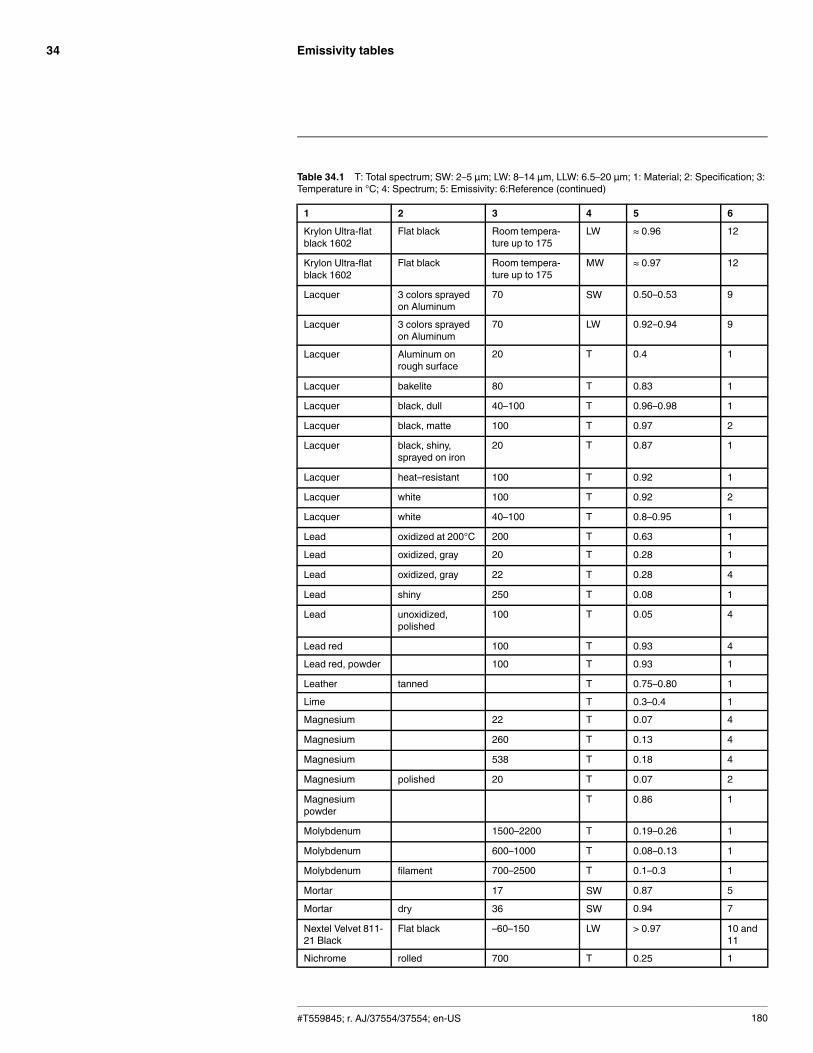
Emissivity tables34
Table 34.1 T: Total spectrum; SW: 2–5 µm; LW: 8–14 µm, LLW: 6.5–20 µm; 1: Material; 2: Specification; 3:Temperature in °C; 4: Spectrum; 5: Emissivity: 6:Reference (continued)
1 2 3 4 5 6
Krylon Ultra-flatblack 1602
Flat black Room tempera-ture up to 175
LW ≈ 0.96 12
Krylon Ultra-flatblack 1602
Flat black Room tempera-ture up to 175
MW ≈ 0.97 12
Lacquer 3 colors sprayedon Aluminum
70 SW 0.50–0.53 9
Lacquer 3 colors sprayedon Aluminum
70 LW 0.92–0.94 9
Lacquer Aluminum onrough surface
20 T 0.4 1
Lacquer bakelite 80 T 0.83 1
Lacquer black, dull 40–100 T 0.96–0.98 1
Lacquer black, matte 100 T 0.97 2
Lacquer black, shiny,sprayed on iron
20 T 0.87 1
Lacquer heat–resistant 100 T 0.92 1
Lacquer white 100 T 0.92 2
Lacquer white 40–100 T 0.8–0.95 1
Lead oxidized at 200°C 200 T 0.63 1
Lead oxidized, gray 20 T 0.28 1
Lead oxidized, gray 22 T 0.28 4
Lead shiny 250 T 0.08 1
Lead unoxidized,polished
100 T 0.05 4
Lead red 100 T 0.93 4
Lead red, powder 100 T 0.93 1
Leather tanned T 0.75–0.80 1
Lime T 0.3–0.4 1
Magnesium 22 T 0.07 4
Magnesium 260 T 0.13 4
Magnesium 538 T 0.18 4
Magnesium polished 20 T 0.07 2
Magnesiumpowder
T 0.86 1
Molybdenum 1500–2200 T 0.19–0.26 1
Molybdenum 600–1000 T 0.08–0.13 1
Molybdenum filament 700–2500 T 0.1–0.3 1
Mortar 17 SW 0.87 5
Mortar dry 36 SW 0.94 7
Nextel Velvet 811-21 Black
Flat black –60–150 LW > 0.97 10 and11
Nichrome rolled 700 T 0.25 1
#T559845; r. AJ/37554/37554; en-US 180
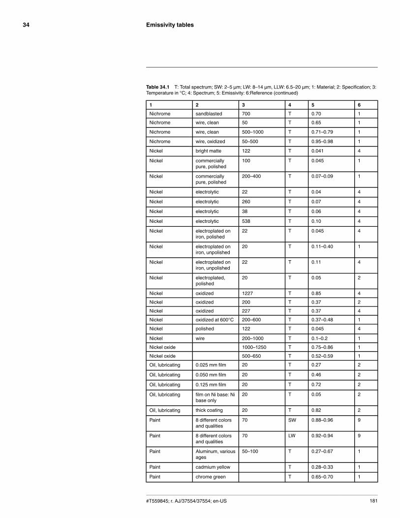
Emissivity tables34
Table 34.1 T: Total spectrum; SW: 2–5 µm; LW: 8–14 µm, LLW: 6.5–20 µm; 1: Material; 2: Specification; 3:Temperature in °C; 4: Spectrum; 5: Emissivity: 6:Reference (continued)
1 2 3 4 5 6
Nichrome sandblasted 700 T 0.70 1
Nichrome wire, clean 50 T 0.65 1
Nichrome wire, clean 500–1000 T 0.71–0.79 1
Nichrome wire, oxidized 50–500 T 0.95–0.98 1
Nickel bright matte 122 T 0.041 4
Nickel commerciallypure, polished
100 T 0.045 1
Nickel commerciallypure, polished
200–400 T 0.07–0.09 1
Nickel electrolytic 22 T 0.04 4
Nickel electrolytic 260 T 0.07 4
Nickel electrolytic 38 T 0.06 4
Nickel electrolytic 538 T 0.10 4
Nickel electroplated oniron, polished
22 T 0.045 4
Nickel electroplated oniron, unpolished
20 T 0.11–0.40 1
Nickel electroplated oniron, unpolished
22 T 0.11 4
Nickel electroplated,polished
20 T 0.05 2
Nickel oxidized 1227 T 0.85 4
Nickel oxidized 200 T 0.37 2
Nickel oxidized 227 T 0.37 4
Nickel oxidized at 600°C 200–600 T 0.37–0.48 1
Nickel polished 122 T 0.045 4
Nickel wire 200–1000 T 0.1–0.2 1
Nickel oxide 1000–1250 T 0.75–0.86 1
Nickel oxide 500–650 T 0.52–0.59 1
Oil, lubricating 0.025 mm film 20 T 0.27 2
Oil, lubricating 0.050 mm film 20 T 0.46 2
Oil, lubricating 0.125 mm film 20 T 0.72 2
Oil, lubricating film on Ni base: Nibase only
20 T 0.05 2
Oil, lubricating thick coating 20 T 0.82 2
Paint 8 different colorsand qualities
70 SW 0.88–0.96 9
Paint 8 different colorsand qualities
70 LW 0.92–0.94 9
Paint Aluminum, variousages
50–100 T 0.27–0.67 1
Paint cadmium yellow T 0.28–0.33 1
Paint chrome green T 0.65–0.70 1
#T559845; r. AJ/37554/37554; en-US 181
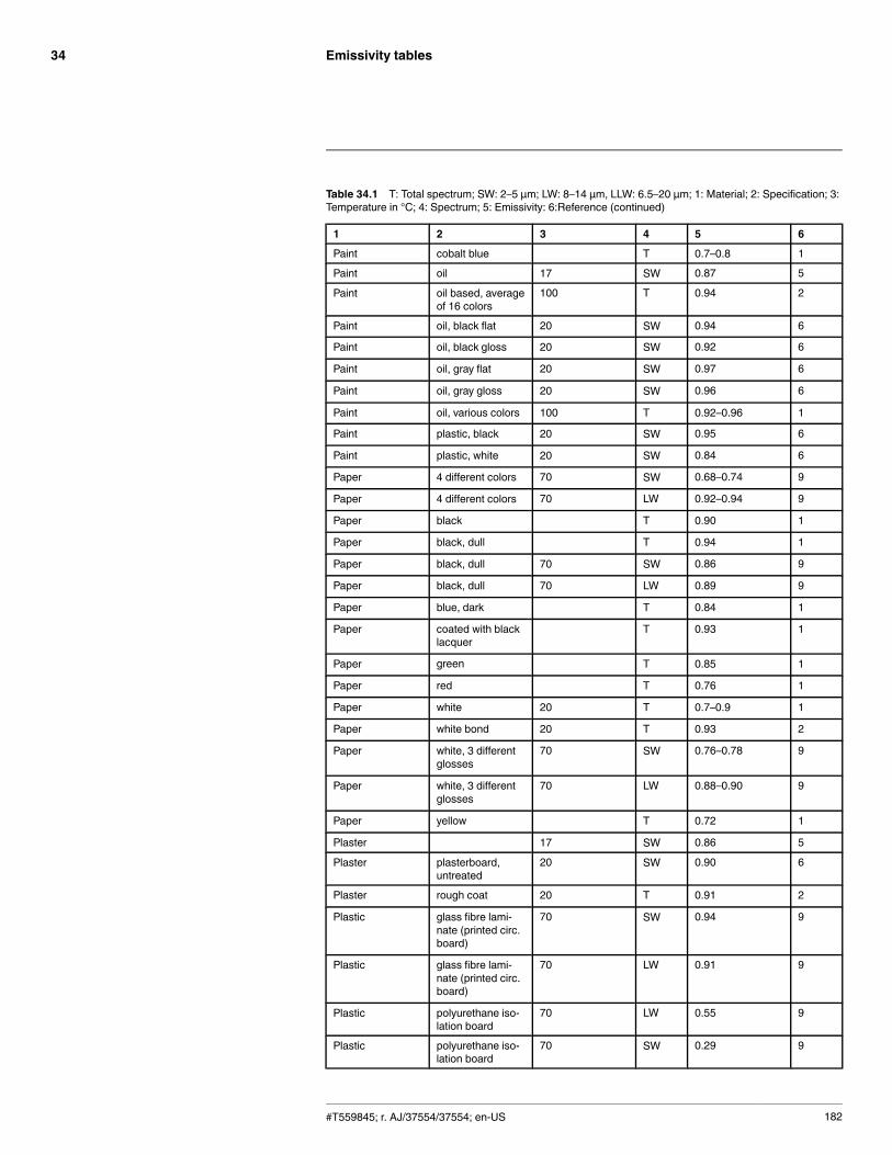
Emissivity tables34
Table 34.1 T: Total spectrum; SW: 2–5 µm; LW: 8–14 µm, LLW: 6.5–20 µm; 1: Material; 2: Specification; 3:Temperature in °C; 4: Spectrum; 5: Emissivity: 6:Reference (continued)
1 2 3 4 5 6
Paint cobalt blue T 0.7–0.8 1
Paint oil 17 SW 0.87 5
Paint oil based, averageof 16 colors
100 T 0.94 2
Paint oil, black flat 20 SW 0.94 6
Paint oil, black gloss 20 SW 0.92 6
Paint oil, gray flat 20 SW 0.97 6
Paint oil, gray gloss 20 SW 0.96 6
Paint oil, various colors 100 T 0.92–0.96 1
Paint plastic, black 20 SW 0.95 6
Paint plastic, white 20 SW 0.84 6
Paper 4 different colors 70 SW 0.68–0.74 9
Paper 4 different colors 70 LW 0.92–0.94 9
Paper black T 0.90 1
Paper black, dull T 0.94 1
Paper black, dull 70 SW 0.86 9
Paper black, dull 70 LW 0.89 9
Paper blue, dark T 0.84 1
Paper coated with blacklacquer
T 0.93 1
Paper green T 0.85 1
Paper red T 0.76 1
Paper white 20 T 0.7–0.9 1
Paper white bond 20 T 0.93 2
Paper white, 3 differentglosses
70 SW 0.76–0.78 9
Paper white, 3 differentglosses
70 LW 0.88–0.90 9
Paper yellow T 0.72 1
Plaster 17 SW 0.86 5
Plaster plasterboard,untreated
20 SW 0.90 6
Plaster rough coat 20 T 0.91 2
Plastic glass fibre lami-nate (printed circ.board)
70 SW 0.94 9
Plastic glass fibre lami-nate (printed circ.board)
70 LW 0.91 9
Plastic polyurethane iso-lation board
70 LW 0.55 9
Plastic polyurethane iso-lation board
70 SW 0.29 9
#T559845; r. AJ/37554/37554; en-US 182
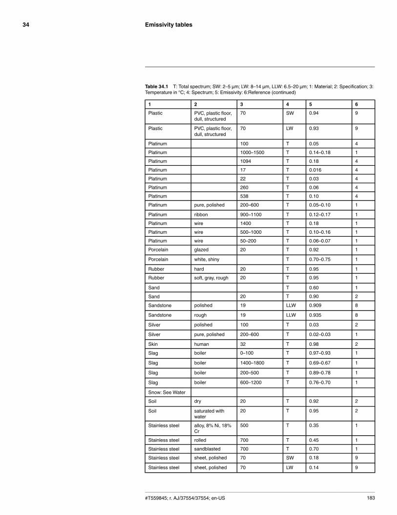
Emissivity tables34
Table 34.1 T: Total spectrum; SW: 2–5 µm; LW: 8–14 µm, LLW: 6.5–20 µm; 1: Material; 2: Specification; 3:Temperature in °C; 4: Spectrum; 5: Emissivity: 6:Reference (continued)
1 2 3 4 5 6
Plastic PVC, plastic floor,dull, structured
70 SW 0.94 9
Plastic PVC, plastic floor,dull, structured
70 LW 0.93 9
Platinum 100 T 0.05 4
Platinum 1000–1500 T 0.14–0.18 1
Platinum 1094 T 0.18 4
Platinum 17 T 0.016 4
Platinum 22 T 0.03 4
Platinum 260 T 0.06 4
Platinum 538 T 0.10 4
Platinum pure, polished 200–600 T 0.05–0.10 1
Platinum ribbon 900–1100 T 0.12–0.17 1
Platinum wire 1400 T 0.18 1
Platinum wire 500–1000 T 0.10–0.16 1
Platinum wire 50–200 T 0.06–0.07 1
Porcelain glazed 20 T 0.92 1
Porcelain white, shiny T 0.70–0.75 1
Rubber hard 20 T 0.95 1
Rubber soft, gray, rough 20 T 0.95 1
Sand T 0.60 1
Sand 20 T 0.90 2
Sandstone polished 19 LLW 0.909 8
Sandstone rough 19 LLW 0.935 8
Silver polished 100 T 0.03 2
Silver pure, polished 200–600 T 0.02–0.03 1
Skin human 32 T 0.98 2
Slag boiler 0–100 T 0.97–0.93 1
Slag boiler 1400–1800 T 0.69–0.67 1
Slag boiler 200–500 T 0.89–0.78 1
Slag boiler 600–1200 T 0.76–0.70 1
Snow: See Water
Soil dry 20 T 0.92 2
Soil saturated withwater
20 T 0.95 2
Stainless steel alloy, 8% Ni, 18%Cr
500 T 0.35 1
Stainless steel rolled 700 T 0.45 1
Stainless steel sandblasted 700 T 0.70 1
Stainless steel sheet, polished 70 SW 0.18 9
Stainless steel sheet, polished 70 LW 0.14 9
#T559845; r. AJ/37554/37554; en-US 183
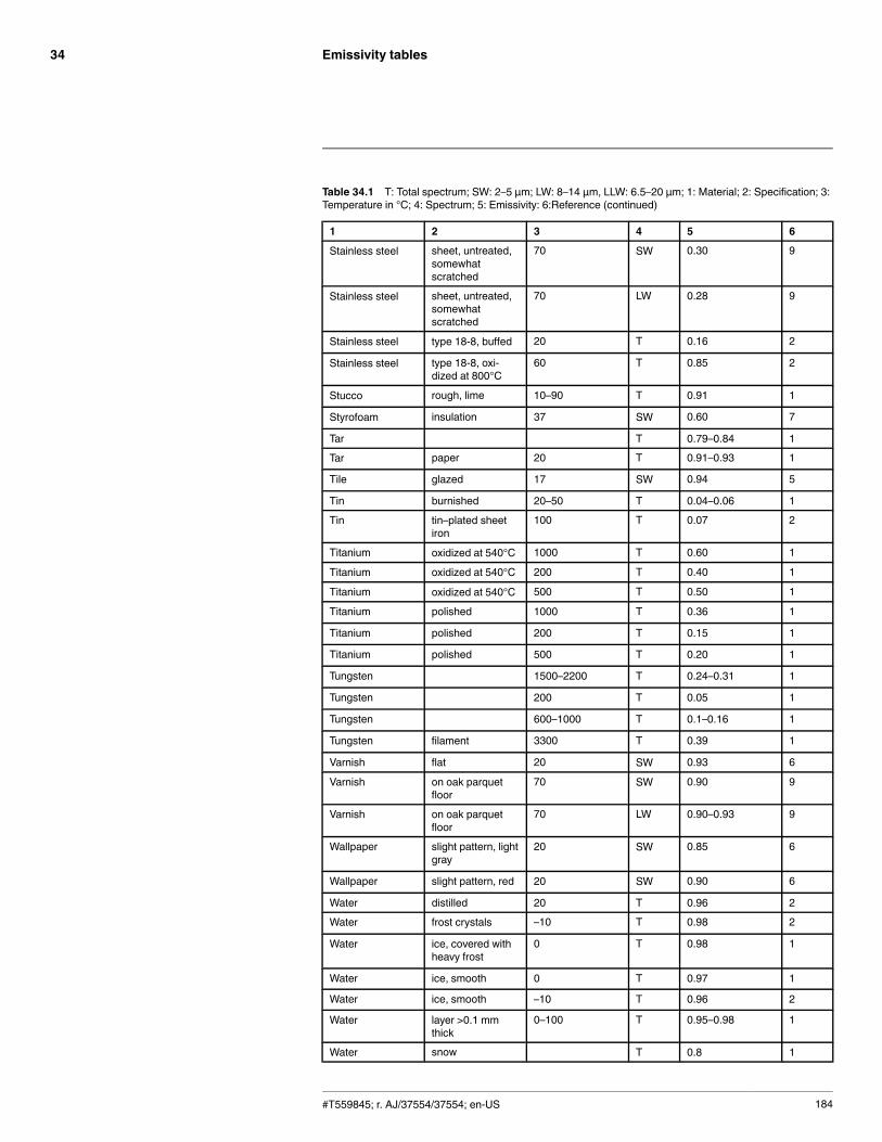
Emissivity tables34
Table 34.1 T: Total spectrum; SW: 2–5 µm; LW: 8–14 µm, LLW: 6.5–20 µm; 1: Material; 2: Specification; 3:Temperature in °C; 4: Spectrum; 5: Emissivity: 6:Reference (continued)
1 2 3 4 5 6
Stainless steel sheet, untreated,somewhatscratched
70 SW 0.30 9
Stainless steel sheet, untreated,somewhatscratched
70 LW 0.28 9
Stainless steel type 18-8, buffed 20 T 0.16 2
Stainless steel type 18-8, oxi-dized at 800°C
60 T 0.85 2
Stucco rough, lime 10–90 T 0.91 1
Styrofoam insulation 37 SW 0.60 7
Tar T 0.79–0.84 1
Tar paper 20 T 0.91–0.93 1
Tile glazed 17 SW 0.94 5
Tin burnished 20–50 T 0.04–0.06 1
Tin tin–plated sheetiron
100 T 0.07 2
Titanium oxidized at 540°C 1000 T 0.60 1
Titanium oxidized at 540°C 200 T 0.40 1
Titanium oxidized at 540°C 500 T 0.50 1
Titanium polished 1000 T 0.36 1
Titanium polished 200 T 0.15 1
Titanium polished 500 T 0.20 1
Tungsten 1500–2200 T 0.24–0.31 1
Tungsten 200 T 0.05 1
Tungsten 600–1000 T 0.1–0.16 1
Tungsten filament 3300 T 0.39 1
Varnish flat 20 SW 0.93 6
Varnish on oak parquetfloor
70 SW 0.90 9
Varnish on oak parquetfloor
70 LW 0.90–0.93 9
Wallpaper slight pattern, lightgray
20 SW 0.85 6
Wallpaper slight pattern, red 20 SW 0.90 6
Water distilled 20 T 0.96 2
Water frost crystals –10 T 0.98 2
Water ice, covered withheavy frost
0 T 0.98 1
Water ice, smooth 0 T 0.97 1
Water ice, smooth –10 T 0.96 2
Water layer >0.1 mmthick
0–100 T 0.95–0.98 1
Water snow T 0.8 1
#T559845; r. AJ/37554/37554; en-US 184
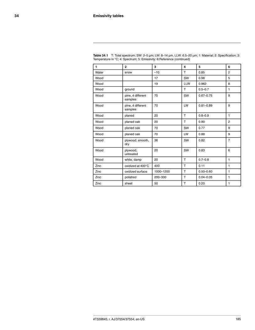
Emissivity tables34
Table 34.1 T: Total spectrum; SW: 2–5 µm; LW: 8–14 µm, LLW: 6.5–20 µm; 1: Material; 2: Specification; 3:Temperature in °C; 4: Spectrum; 5: Emissivity: 6:Reference (continued)
1 2 3 4 5 6
Water snow –10 T 0.85 2
Wood 17 SW 0.98 5
Wood 19 LLW 0.962 8
Wood ground T 0.5–0.7 1
Wood pine, 4 differentsamples
70 SW 0.67–0.75 9
Wood pine, 4 differentsamples
70 LW 0.81–0.89 9
Wood planed 20 T 0.8–0.9 1
Wood planed oak 20 T 0.90 2
Wood planed oak 70 SW 0.77 9
Wood planed oak 70 LW 0.88 9
Wood plywood, smooth,dry
36 SW 0.82 7
Wood plywood,untreated
20 SW 0.83 6
Wood white, damp 20 T 0.7–0.8 1
Zinc oxidized at 400°C 400 T 0.11 1
Zinc oxidized surface 1000–1200 T 0.50–0.60 1
Zinc polished 200–300 T 0.04–0.05 1
Zinc sheet 50 T 0.20 1
#T559845; r. AJ/37554/37554; en-US 185
A note on the technical production of this publicationThis publication was produced using XML — the eXtensible Markup Language. For more information aboutXML, please visit http://www.w3.org/XML/A note on the typeface used in this publicationThis publication was typeset using Linotype Helvetica™World. Helvetica™ was designed by Max Miedinger(1910–1980)LOEF (List Of Effective Files)T501038.xml; en-US; AJ; 37554; 2016-09-30T505552.xml; en-US; 9599; 2013-11-05T505699.xml; en-US; 32147; 2016-01-12T505469.xml; en-US; 23215; 2015-02-19T505013.xml; en-US; 35155; 2016-04-21T505700.xml; en-US; 25106; 2015-04-28T505701.xml; en-US; 32095; 2016-01-12T505702.xml; en-US; 32095; 2016-01-12T505703.xml; en-US; 32120; 2016-01-12T505704.xml; en-US; 32120; 2016-01-12T505705.xml; en-US; 32120; 2016-01-12T505706.xml; en-US; 32120; 2016-01-12T505707.xml; en-US; 32120; 2016-01-12T505708.xml; en-US; 32527; 2016-01-19T505709.xml; en-US; 32120; 2016-01-12T505710.xml; en-US; 32120; 2016-01-12T505711.xml; en-US; 32120; 2016-01-12T505713.xml; en-US; 32120; 2016-01-12T505715.xml; en-US; 32120; 2016-01-12T505716.xml; en-US; 32120; 2016-01-12T505787.xml; en-US; 37547; 2016-09-30T505470.xml; en-US; 12154; 2014-03-06T505012.xml; en-US; 32556; 2016-01-20T505007.xml; en-US; 35155; 2016-04-21T505004.xml; en-US; 35155; 2016-04-21T505000.xml; en-US; 35155; 2016-04-21T505005.xml; en-US; 35155; 2016-04-21T505001.xml; en-US; 32554; 2016-01-20T505006.xml; en-US; 32555; 2016-01-20T505002.xml; en-US; 33518; 2016-02-18
#T559845; r. AJ/37554/37554; en-US 186


last page
Publ. No.: T559845Release: AJCommit: 37554Head: 37554Language: en-USModified: 2016-09-30Formatted: 2016-09-30
Websitehttp://www.flir.comCustomer supporthttp://support.flir.comCopyright© 2016, FLIR Systems, Inc. All rights reserved worldwide.DisclaimerSpecifications subject to change without further notice. Models and accessories subject to regional market considerations. License procedures may apply. Productsdescribed herein may be subject to US Export Regulations. Please refer to [email protected] with any questions.