user’s manual ethernet/ip communication interface · connect the ethernet cable to the ethernet...
TRANSCRIPT
User’sManual
Yokogawa Electric Corporation
DX1000/DX1000N/DX2000EtherNet/IPCommunication Interface
IM 04L41B01-18E2nd Edition
�IM 04L4�B0�-�8E
Thank you for purchasing Daqstation DX�000, DX�000N, or DX2000 (Hereafter, called "DX").This manual explains the EtherNet/IP communication function of the DX. Read this manual together with other User's Manuals (IM04L4�B0�-0�E, IM04L42B0�-0�E, and IM04L4�B0�-�7E).
Notes● Thecontentofthismanualmaychangewithoutpriornoticeinviewof improvingthe
performance and function.● Weensure the content of thismanual. If, however, thereareanymistakesor
questionable points, contact our branch office, branch store, or business office.● Reprintingor reproductionof all or parts of the content of thismanual is prohibited
without permission.● Wedevelopedand created theTCP/IP softwareandTCP/IP softwaredocuments
of this product based on BSD Networking Software Release � licensed from the UniversityofCalifornia.
Trademarks● vigilantplant,DAQSTATION,Daqstation, andDXAdvancedareour registered
trademarks. ● Microsoft andWindowsare the registered trademarksor trademarksofMicrosoft
CorporationintheUnitedStatesandothercountries.● AdobeandAcrobatare the registered trademarksor trademarksofAdobeSystems
Incorporated.● KerberosisatrademarkoftheMassachusettsInstituteofTechnology(MIT).● Other product and company names described in thismanual are registered
trademarksortrademarksoftheirrespectivecompanies.● Thismanual doesnot displaymarks ®and™ for the registered trademarksor
trademarks of each company.
HistoryNovember2008: 1stEditionMarch2010: 2ndEdition
2ndEdition:March2010(YK)AllRightReserved,Copyright©2008,YokogawaElectricCorporation
2 IM 04L4�B0�-�8E
Symbols Used in This Manual
● Units• k:Denotes1000.Examples:5kg,100kHz• K:Denotes1024.Example:640Kbytes
● CautionarynotesInthisUser'sManual,cautionarynotesaredistinguishedbythefollowingsymbols:
Refer to corresponding location on the instrument. This symbol appears on dangerous locations on the instrument which require special instructions for proper handling or use. The same symbol appears in the corresponding place in the manual to identify those instructions.
WARNING Calls attention to actions or conditions that could cause serious
injury or death to the user, and precautions that can be taken to prevent such occurrences.
CAUTION Calls attentions to actions or conditions that could cause light
injury to the user or damage to the instrument or user’s data, and precautions that can be taken to prevent such occurrences.
Note Callsattentiontoinformationthatisimportantforproperoperationofthe instrument.
● Boldcharacters Denotes key or character string that appear on the DX screen. The symbol indicates the key operation and menu selection procedure on the DX.
�IM 04L4�B0�-�8E
Assumption of ExplanationTheexplanation in thismanualassumes that theDX isconnectedviacommunicationswithRockwellAutomation'sProgrammable LogicController (PLC)of theAllen-Bradleybrand.The basic items for this configuration are explained. For the operation procedures ofRockwellAutomationproducts,seetheuser'smanualsoftheseproducts.
ThismanualisintendedforthosewhohaveusedanAllen-BradleyPLCandEtherNet/IP.
In this manual, the screens of the DX�000 are used. The content displayed on the DX2000 screens are not different from those displayed on the DX�000 screen.
4 IM 04L4�B0�-�8E
Contents
Symbols Used in This Manual ...................................................................................................................2AssumptionofExplanation ........................................................................................................................�
Introduction of Features ......................................................................................................................5EtherNet/IP ................................................................................................................................................5WhattheDXCanDo .................................................................................................................................6Settings of the DX ......................................................................................................................................6AccesstotheDX .......................................................................................................................................6
ConnectiontoaNetwork .....................................................................................................................7CableConnection ......................................................................................................................................7Settings of the DX ......................................................................................................................................7Other ..........................................................................................................................................................7
PreparationforPLC ............................................................................................................................8EDS File .....................................................................................................................................................8SystemConfiguration ................................................................................................................................8
Explicit Message .................................................................................................................................9SystemConfigurationonPLC ...................................................................................................................9Data on the DX ........................................................................................................................................�2
I/OMessages ....................................................................................................................................��SystemConfigurationonPLC .................................................................................................................��Data on the DX ........................................................................................................................................��
CommunicationConsiderations ........................................................................................................�4AboutCommunicationInterval .................................................................................................................�4AccesstoNon-existentData ...................................................................................................................�4WhentheDXDataTypeDiffersfromtheDataTypeSpecifiedinaCommand .......................................�4OnModelswiththePROFIBUS-DPInterface(/CP1option) ...................................................................�5
Specifications ....................................................................................................................................�6ExampleofanExplicitMessageUsingRSLogix5000 .....................................................................�7ExampleofI/OMessageUsingRSLogix5000 .................................................................................�9Index .................................................................................................................................................20
5IM 04L4�B0�-�8E
Introduction of Features
EtherNet/IPEtherNet/IP is a protocol that extends Common IndustrialProtocol (CIP) toEthernet.TheuseofEthernetenableshigh-speedandperiodicexchangeofmassivecontrolandmonitoringdatabetweencontroldevicesplacedatdispersedlocations.Devices that supportEtherNet/IPareavailable frommany vendors.Among them,RockwellAutomation'sProgrammable LogicController (PLC)andRemote I/Oof theAllen-Bradley brandarewidely used.Yokogawa'sDX, equippedwith theEtherNet/IPserverfunction,supportscommunicationswiththesePLCs.
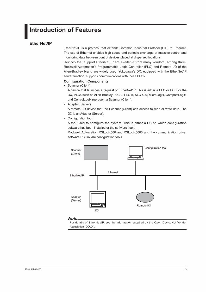
Configuration Components• Scanner (Client) AdevicethatlaunchesarequestonEtherNet/IP.ThisiseitheraPLCorPC.Forthe
DX,PLCssuchasAllen-BradleyPLC-2,PLC-5,SLC500,MicroLogix,CompactLogix,andControlLogixrepresentaScanner(Client).
• Adapter(Server) Aremote I/Odevice that theScanner(Client)canaccesstoreadorwritedata.The
DXisanAdapter(Server).• Configurationtool A tool used to configure the system.This is either aPConwhich configuration
software has been installed or the software itself. RockwellAutomationRSLogix500andRSLogix5000and the communication driver
software RSLinx are configuration tools.
EtherNet/IP
DX
Scanner(Client)
Adapter(Server)
Ethernet
Configuration tool
Remote I/O
NoteFor details ofEtherNet/IP, see the information suppliedby theOpenDeviceNetVenderAssociation(ODVA).
6 IM 04L4�B0�-�8E
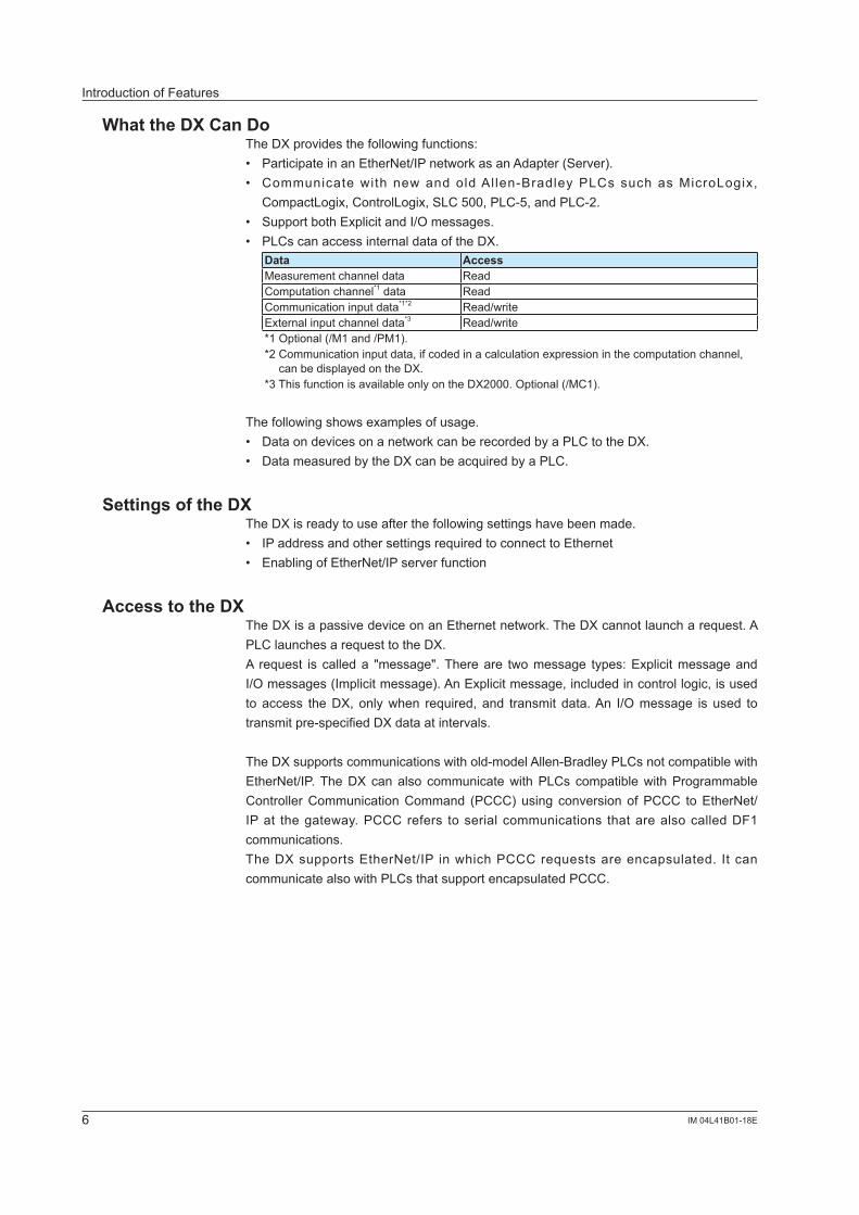
What the DX Can DoTheDXprovidesthefollowingfunctions:• ParticipateinanEtherNet/IPnetworkasanAdapter(Server).• Communicate with new and oldAl len-Bradley PLCs such asMicroLogix,
CompactLogix,ControlLogix,SLC500,PLC-5,andPLC-2.• SupportbothExplicitandI/Omessages.• PLCscanaccessinternaldataoftheDX.
Data AccessMeasurement channel data ReadComputationchannel*� data ReadCommunicationinputdata*�*2 Read/writeExternal input channel data*� Read/write*1Optional(/M1and/PM1).*2Communicationinputdata,ifcodedinacalculationexpressioninthecomputationchannel,
can be displayed on the DX.*3ThisfunctionisavailableonlyontheDX2000.Optional(/MC1).
The following shows examples of usage.• DataondevicesonanetworkcanberecordedbyaPLCtotheDX.• DatameasuredbytheDXcanbeacquiredbyaPLC.
Settings of the DXTheDXisreadytouseafterthefollowingsettingshavebeenmade.• IP address and other settings required to connect to Ethernet• EnablingofEtherNet/IPserverfunction
Access to the DXTheDXisapassivedeviceonanEthernetnetwork.TheDXcannotlauncharequest.APLClaunchesarequesttotheDX.A request is calleda "message".Thereare twomessage types:ExplicitmessageandI/Omessages(Implicitmessage).AnExplicitmessage,includedincontrollogic,isusedto access theDX, onlywhen required, and transmit data.An I/Omessage is used totransmitpre-specifiedDXdataatintervals.
TheDXsupportscommunicationswithold-modelAllen-BradleyPLCsnotcompatiblewithEtherNet/IP.TheDXcanalso communicatewithPLCs compatiblewithProgrammableControllerCommunicationCommand (PCCC)using conversionofPCCC toEtherNet/IPat thegateway.PCCC refers to serial communications that arealso calledDF� communications.TheDXsupportsEtherNet/IP inwhichPCCC requestsareencapsulated. It cancommunicatealsowithPLCsthatsupportencapsulatedPCCC.
Introduction of Features
7IM 04L4�B0�-�8E
Connection to a Network
Cable ConnectionConnecttheEthernetcabletotheEthernetportprovidedonthebackoftheDX.
Ethernet cable
CAUTIONBe sure to connect an Ethernet cable with an FCC-compliant plug. Otherwise, the MV may malfunction.
Settings of the DXIP Address, Host Information, and DNS Setting, etc.See Section �.� of the Communication Interface User's Manual (IM04L41B01-17E).
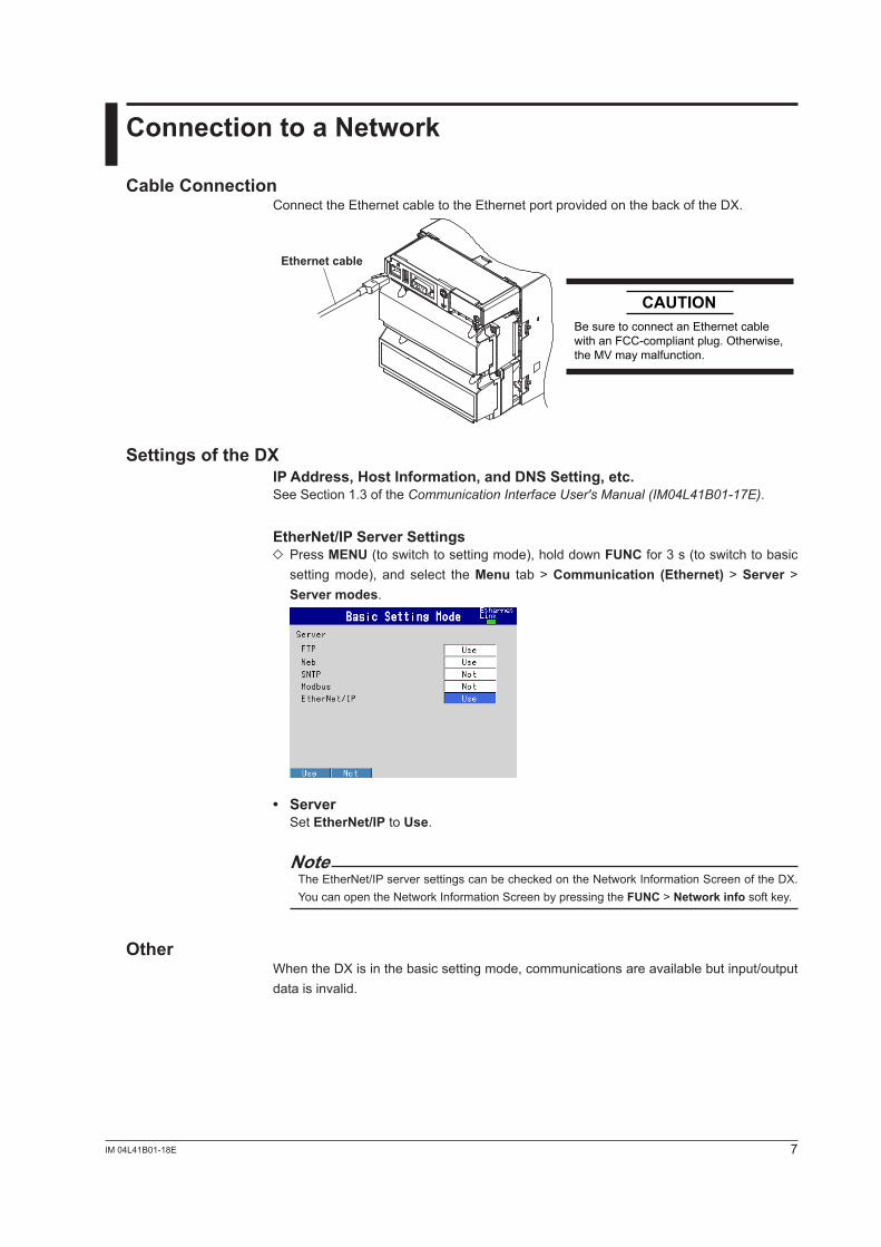
EtherNet/IP Server Settings Press MENU (to switch to setting mode), hold down FUNC for � s (to switch to basic setting mode), and select the Menu tab > Communication (Ethernet) > Server > Server modes.
• Server Set EtherNet/IP to Use.
NoteTheEtherNet/IPserversettingscanbecheckedontheNetworkInformationScreenoftheDX.YoucanopentheNetworkInformationScreenbypressingtheFUNC > Network info soft key.
OtherWhentheDXisinthebasicsettingmode,communicationsareavailablebutinput/outputdataisinvalid.
8 IM 04L4�B0�-�8E
Preparation for PLC
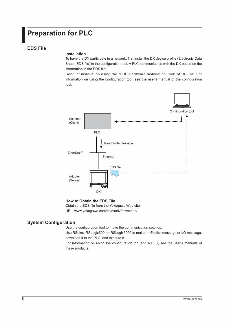
EDS FileInstallationTohavetheDXparticipateinanetwork,firstinstalltheDXdeviceprofile(ElectronicDataSheet;EDSfile)intheconfigurationtool.APLCcommunicateswiththeDXbasedontheinformation in the EDS file.Conduct installation using the "EDSHardware InstallationTool" ofRSLinx. Forinformation on using the configuration tool, see the user's manual of the configuration tool.
EtherNet/IP
DX
Scanner(Client)
Adapter(Server)
PLC
Configuration tool
Read/Write message
Ethernet
EDS file
How to Obtain the EDS FileObtaintheEDSfilefromtheYokogawaWebsite:URL:www.yokogawa.com/ns/dxadv/download/
System ConfigurationUse the configuration tool to make the communication settings.UseRSLinx,RSLogix500,orRSLogix5000tomakeanExplicitmessageorI/Omessage,downloadittothePLC,andexecuteit.For informationonusing the configuration tool andaPLC, see theuser'smanuals ofthese products.
9IM 04L4�B0�-�8E
Explicit Message
AnExplicit message is a point-to-point, request/response-type communication.
System Configuration on PLCUse the configuration tool to code an Explicit message as an MSG instruction in the control logic. In the MSG instruction, set all the information includinga target device,targetregister,andread/write.DownloadthecreatedcontrollogictoaPLCandexecuteit.OntheDX,thedatacounttobeaccessedperMSGinstructionshouldbe100orless.
In Case of PLC-2, PLC-5, and SLC• Commands WhencreatinganMSGinstruction,specifyacommand.TheDXsupportsthefollowing
commands:Target PLC Command namePLC-2 PLC2UnprotectedRead/WritePLC-5 PLC5WordRangeRead/Write
PLC5TypedRead/WriteSLC SLCTypedRead/Write
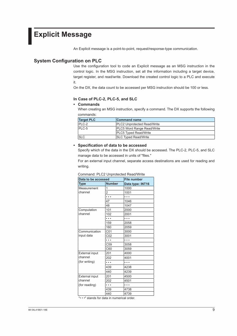
• Specification of data to be accessed SpecifywhichofthedataintheDXshouldbeaccessed.ThePLC-2,PLC-5,andSLC
manage data to be accessed in units of "files." For an external input channel, separate access destinations are used for reading and
writing.
Command:PLC2UnprotectedRead/WriteData to be accessed File number
Data type: INT16Type NumberMeasurement channel
� �0002 �00�• • • • • •47 104648 �047
Computationchannel
�0� 2000�02 200�• • • • • •159 2058160 2059
Communicationinput data
C01 �000C02 �00�• • • • • •C59 3058C60 3059
External input channel(for writing)
20� 4000202 400�• • • • • •4�9 42�8440 42�9
External input channel(for reading)
20� 4500202 4501• • • • • •4�9 47�8440 47�9
"• • •" stands for data in numerical order.
�0 IM 04L4�B0�-�8E
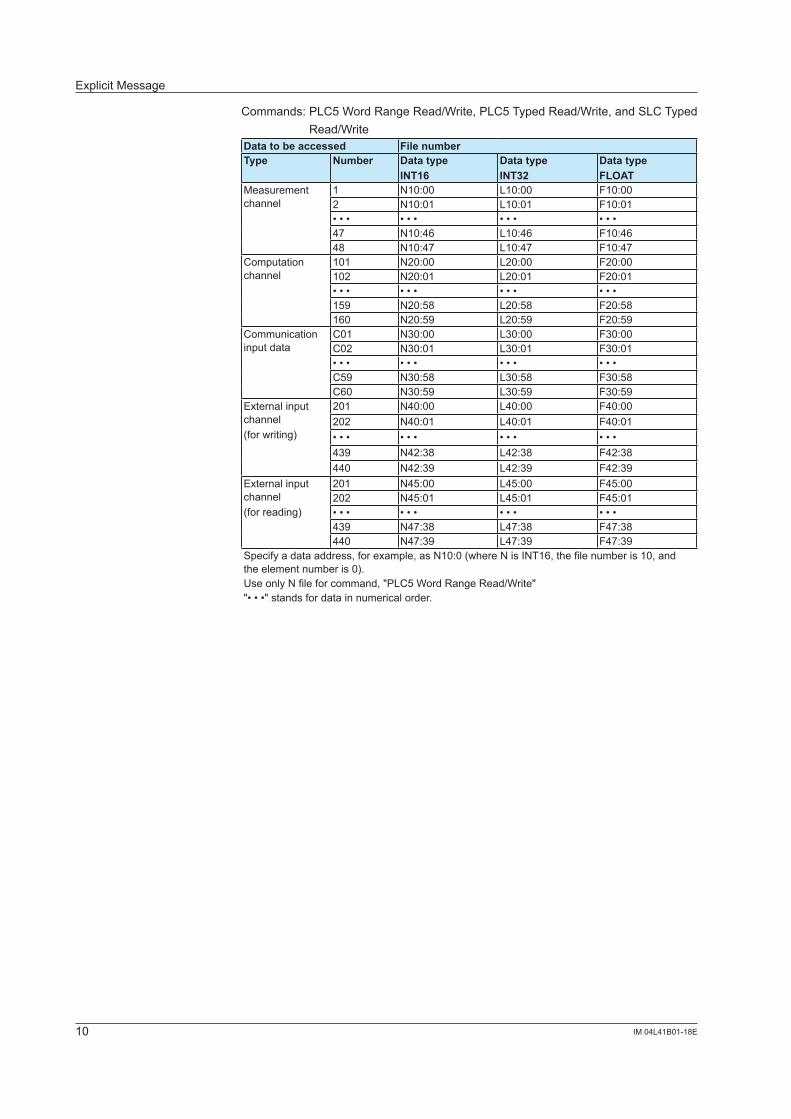
Commands:PLC5WordRangeRead/Write,PLC5TypedRead/Write,andSLCTypedRead/Write
Data to be accessed File numberType Number Data type
INT16Data typeINT32
Data typeFLOAT
Measurement channel
� N10:00 L10:00 F10:002 N10:01 L10:01 F10:01• • • • • • • • • • • •47 N10:46 L10:46 F10:4648 N10:47 L10:47 F10:47
Computationchannel
�0� N20:00 L20:00 F20:00�02 N20:01 L20:01 F20:01• • • • • • • • • • • •159 N20:58 L20:58 F20:58160 N20:59 L20:59 F20:59
Communicationinput data
C01 N30:00 L30:00 F30:00C02 N30:01 L30:01 F30:01• • • • • • • • • • • •C59 N30:58 L30:58 F30:58C60 N30:59 L30:59 F30:59
External input channel (for writing)
20� N40:00 L40:00 F40:00202 N40:01 L40:01 F40:01• • • • • • • • • • • •4�9 N42:38 L42:38 F42:38440 N42:39 L42:39 F42:39
External input channel(for reading)
20� N45:00 L45:00 F45:00202 N45:01 L45:01 F45:01• • • • • • • • • • • •4�9 N47:38 L47:38 F47:38440 N47:39 L47:39 F47:39
Specifyadataaddress,forexample,asN10:0(whereNisINT16,thefilenumberis10,andthe element number is 0).UseonlyNfileforcommand,"PLC5WordRangeRead/Write""• • •" stands for data in numerical order.
Explicit Message
��IM 04L4�B0�-�8E
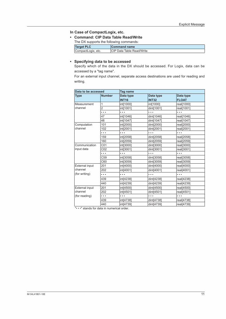
In Case of CompactLogix, etc.• Command: CIP Data Table Read/Write TheDXsupportsthefollowingcommands:
Target PLC Command nameCompactLogix,etc. CIPDataTableRead/Write
• Specifying data to be accessed Specify which of the data in the DX should be accessed. For Logix, data can be
accessed by a "tag name". For an external input channel, separate access destinations are used for reading and
writing.
Data to be accessed Tag nameType Number Data type
INT16Data typeINT32
Data typeFLOAT
Measurement channel
� int[�000] int[�000] real[�000]2 int[�00�] dint[�00�] real[�00�]• • • • • • • • • • • •47 int[1046] dint[1046] real[1046]48 int[�047] dint[�047] real[�047]
Computationchannel
�0� int[2000] dint[2000] real[2000]�02 int[200�] dint[200�] real[200�]• • • • • • • • • • • •159 int[2058] dint[2058] real[2058]160 int[2059] dint[2059] real[2059]
Communicationinput data
C01 int[�000] dint[�000] real[�000]C02 int[�00�] dint[�00�] real[�00�]• • • • • • • • • • • •C59 int[3058] dint[3058] real[3058]C60 int[3059] dint[3059] real[3059]
External input channel(for writing)
20� int[4000] dint[4000] real[4000]202 int[400�] dint[400�] real[400�]• • • • • • • • • • • •4�9 int[42�8] dint[42�8] real[42�8]440 int[42�9] dint[42�9] real[42�9]
External input channel(for reading)
20� int[4500] dint[4500] real[4500]202 int[4501] dint[4501] real[4501]• • • • • • • • • • • •4�9 int[47�8] dint[47�8] real[47�8]440 int[47�9] dint[47�9] real[47�9]
"• • •" stands for data in numerical order.
Explicit Message
�2 IM 04L4�B0�-�8E
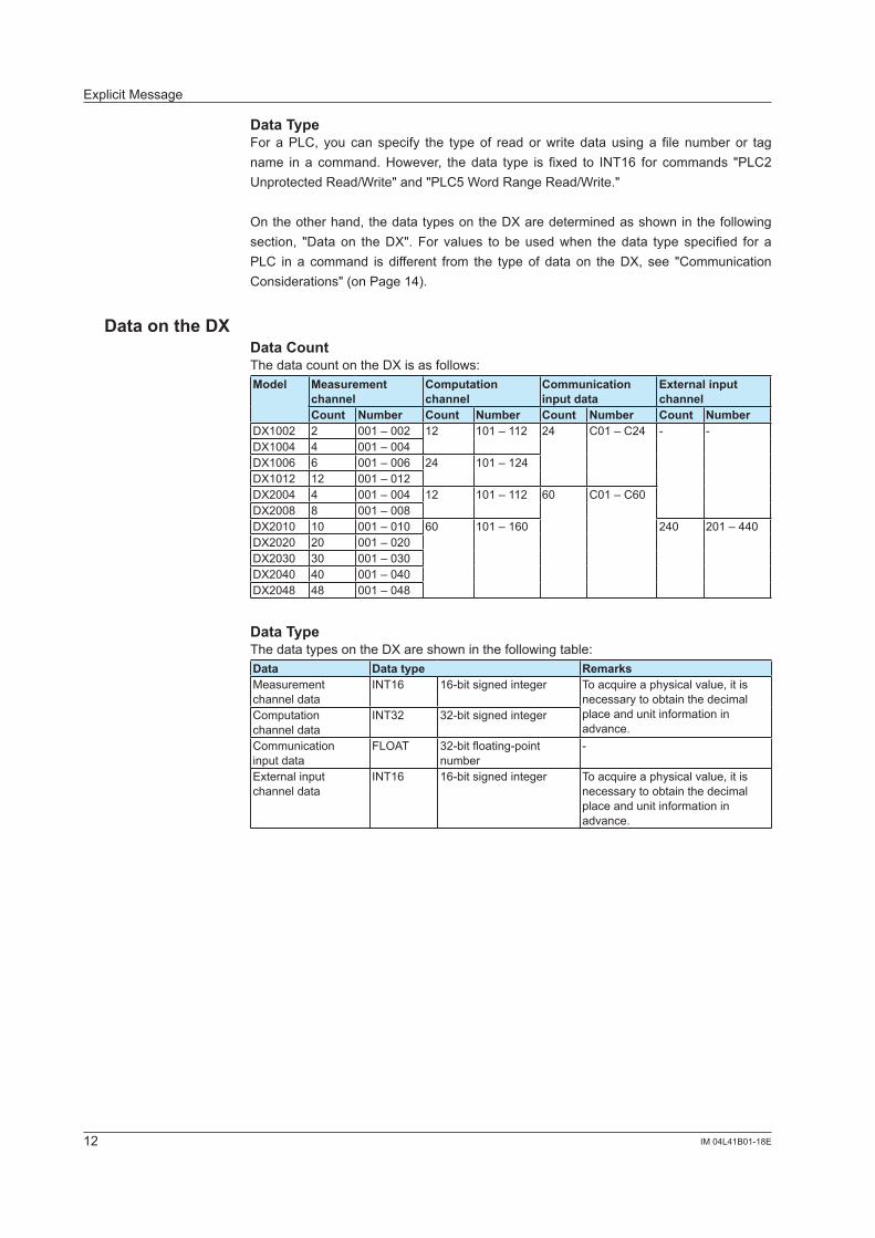
Data TypeFor aPLC, you can specify the typeof readorwrite data usinga file number or tagname in a command.However, thedata type is fixed to INT16 for commands "PLC2UnprotectedRead/Write"and"PLC5WordRangeRead/Write."
Ontheotherhand,thedatatypesontheDXaredeterminedasshowninthefollowingsection, "Dataon theDX".For values to beusedwhen thedata type specified for aPLC in a command is different from the typeof dataon theDX, see "CommunicationConsiderations"(onPage14).
Data on the DXData CountThedatacountontheDXisasfollows:Model Measurement
channelComputation channel
Communication input data
External input channel
Count Number Count Number Count Number Count NumberDX�002 2 00� – 002 �2 �0� – ��2 24 C01–C24 - -DX�004 4 00� – 004DX1006 6 001–006 24 �0� – �24DX�0�2 �2 00� – 0�2DX2004 4 00� – 004 �2 �0� – ��2 60 C01–C60DX2008 8 00� – 008DX20�0 �0 00� – 0�0 60 101–160 240 20� – 440DX2020 20 00� – 020DX20�0 �0 00� – 0�0DX2040 40 00� – 040DX2048 48 00� – 048
Data TypeThedatatypesontheDXareshowninthefollowingtable:Data Data type RemarksMeasurement channel data
INT16 16-bitsignedinteger Toacquireaphysicalvalue,itisnecessary to obtain the decimal place and unit information in advance.
Computationchannel data
INT�2 �2-bit signed integer
Communicationinput data
FLOAT �2-bit floating-point number
-
External input channel data
INT16 16-bitsignedinteger Toacquireaphysicalvalue,itisnecessary to obtain the decimal place and unit information in advance.
Explicit Message
��IM 04L4�B0�-�8E
I/O Messages
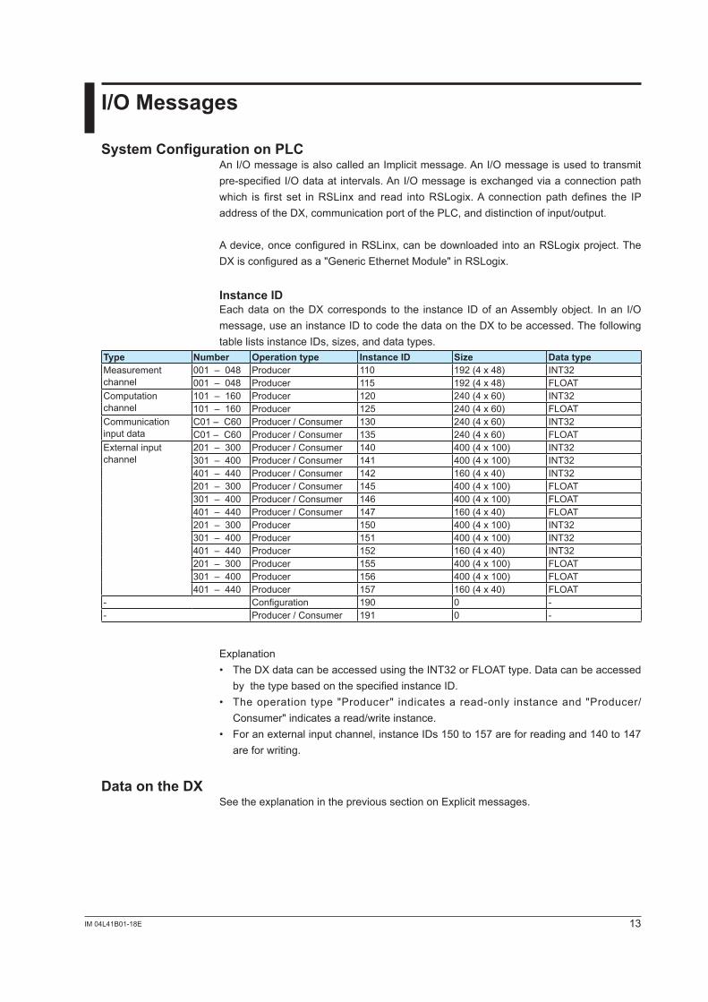
System Configuration on PLCAnI/OmessageisalsocalledanImplicitmessage.AnI/Omessageisusedtotransmitpre-specifiedI/Odataat intervals.AnI/Omessageisexchangedviaaconnectionpathwhich is first set inRSLinxand read intoRSLogix.A connectionpathdefines the IPaddressoftheDX,communicationportofthePLC,anddistinctionofinput/output.
Adevice,onceconfigured inRSLinx,canbedownloaded intoanRSLogixproject.TheDX is configured as a "Generic Ethernet Module" in RSLogix.
Instance IDEach data on the DX corresponds to the instance ID of an Assemblyobject. Inan I/Omessage, use an instance ID to code the data on the DX to be accessed. The following tablelistsinstanceIDs,sizes,anddatatypes.
Type Number Operation type Instance ID Size Data typeMeasurement channel
00� – 048 Producer ��0 �92 (4 x 48) INT�200� – 048 Producer 115 �92 (4 x 48) FLOAT
Computationchannel
101–160 Producer �20 240(4x60) INT�2101–160 Producer 125 240(4x60) FLOAT
Communicationinput data
C01–C60 Producer / Consumer ��0 240(4x60) INT�2C01–C60 Producer/Consumer 135 240(4x60) FLOAT
External input channel
20� – �00 Producer/Consumer �40 400 (4 x �00) INT�2�0� – 400 Producer/Consumer �4� 400 (4 x �00) INT�240� – 440 Producer/Consumer �42 160(4x40) INT�220� – �00 Producer/Consumer 145 400 (4 x �00) FLOAT�0� – 400 Producer/Consumer 146 400 (4 x �00) FLOAT40� – 440 Producer/Consumer �47 160(4x40) FLOAT20� – �00 Producer 150 400 (4 x �00) INT�2�0� – 400 Producer 151 400 (4 x �00) INT�240� – 440 Producer 152 160(4x40) INT�220� – �00 Producer 155 400 (4 x �00) FLOAT�0� – 400 Producer 156 400 (4 x �00) FLOAT40� – 440 Producer 157 160(4x40) FLOAT
- Configuration �90 0 -- Producer/Consumer �9� 0 -
Explanation• TheDXdatacanbeaccessedusingtheINT32orFLOATtype.Datacanbeaccessed
by the type based on the specified instance ID.• The operation type "Producer" indicates a read-only instance and "Producer/
Consumer"indicatesaread/writeinstance.• Foranexternalinputchannel,instanceIDs150to157areforreadingand140to147
are for writing.
Data on the DXSeetheexplanationintheprevioussectiononExplicitmessages.
14 IM 04L41B01-18E
Communication Considerations
About Communication IntervalData UpdateThe DX data is updated in a scan interval. Even if a PLC accesses the data at shorter intervals than the DX scan intervals, the data is updated only at scan intervals.
Communication IntervalA PLC should access the DX at intervals of 125 ms or longer.
* This is required to maintain compatibility with other protocols supported by the DX than EtherNet/IP.
Access to Non-existent DataIf non-existent data is accessed, either of the following operations occur.• 0 is read if non-existent data is read.• Nothing is done if non-existent data is written.
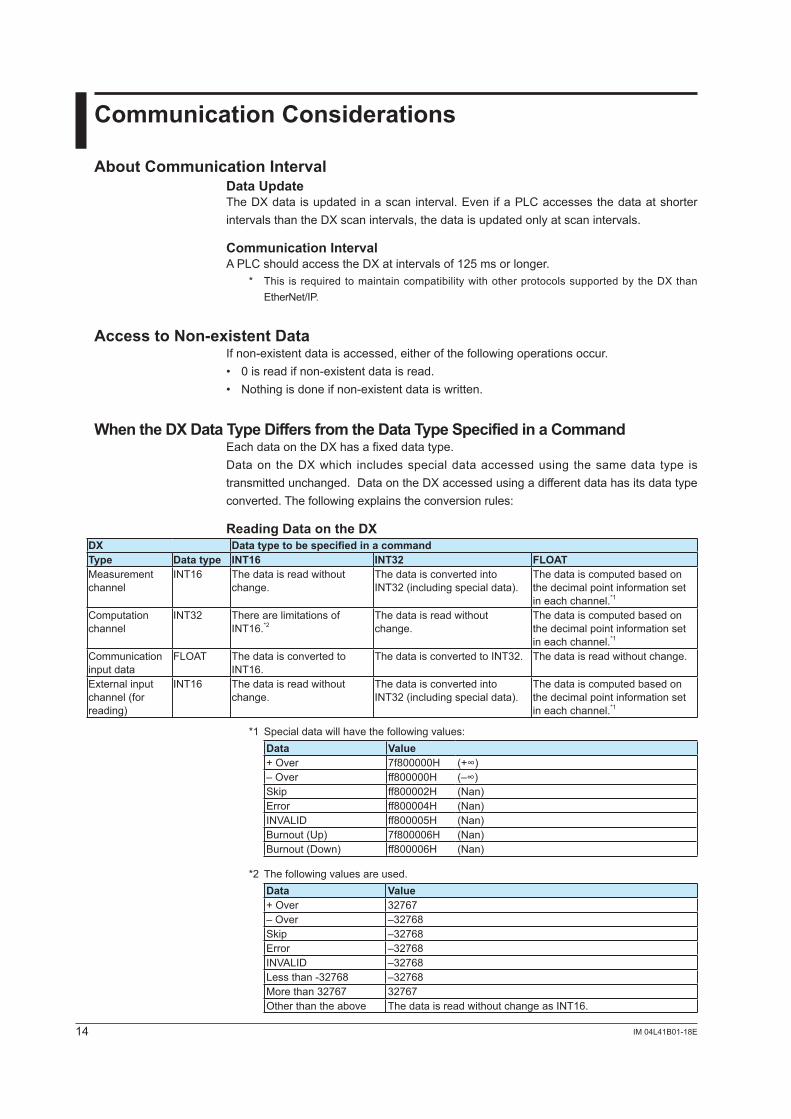
When the DX Data Type Differs from the Data Type Specified in a CommandEach data on the DX has a fixed data type.Data on the DX which includes special data accessed using the same data type is transmitted unchanged. Data on the DX accessed using a different data has its data type converted. The following explains the conversion rules:
Reading Data on the DXDX Data type to be specified in a commandType Data type INT16 INT32 FLOATMeasurement channel
INT16 The data is read without change.
The data is converted into INT32 (including special data).
The data is computed based on the decimal point information set in each channel.*1
Computation channel
INT32 There are limitations of INT16.*2
The data is read without change.
The data is computed based on the decimal point information set in each channel.*1
Communication input data
FLOAT The data is converted to INT16.
The data is converted to INT32. The data is read without change.
External input channel (for reading)
INT16 The data is read without change.
The data is converted into INT32 (including special data).
The data is computed based on the decimal point information set in each channel.*1
*1 Special data will have the following values:Data Value+ Over 7f800000H (+∞)– Over ff800000H (–∞)Skip ff800002H (Nan)Error ff800004H (Nan)INVALID ff800005H (Nan)Burnout (Up) 7f800006H (Nan)Burnout (Down) ff800006H (Nan)
*2 The following values are used.Data Value+ Over 32767– Over –32768Skip –32768Error –32768INVALID –32768Less than -32768 –32768More than 32767 32767Other than the above The data is read without change as INT16.
15IM 04L4�B0�-�8E
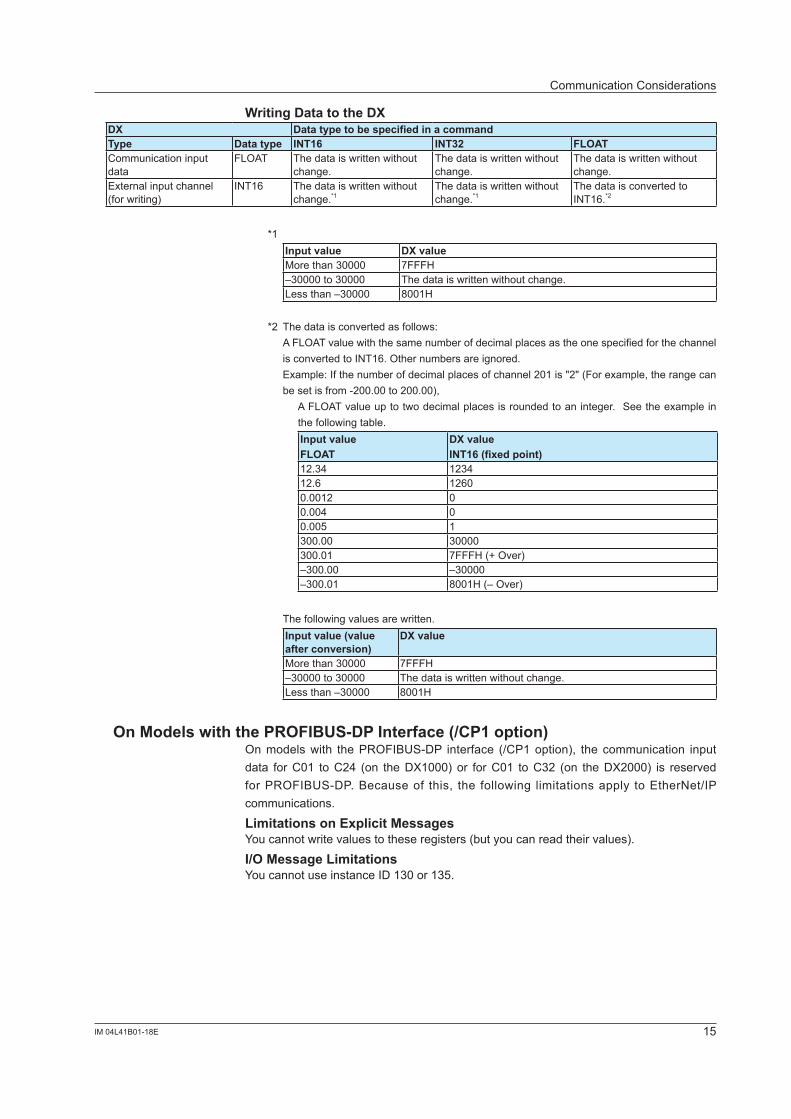
Writing Data to the DXDX Data type to be specified in a commandType Data type INT16 INT32 FLOATCommunicationinputdata
FLOAT The data is written without change.
The data is written without change.
The data is written without change.
External input channel (for writing)
INT16 The data is written without change.*�
The data is written without change.*�
ThedataisconvertedtoINT16.*2
*� Input value DX valueMore than �0000 7FFFH–�0000 to �0000 The data is written without change.Less than –�0000 800�H
*2 Thedataisconvertedasfollows: AFLOATvaluewiththesamenumberofdecimalplacesastheonespecifiedforthechannel
isconvertedtoINT16.Othernumbersareignored. Example:Ifthenumberofdecimalplacesofchannel201is"2"(Forexample,therangecan
be set is from -200.00 to 200.00), AFLOATvalueuptotwodecimalplacesisroundedtoaninteger.Seetheexamplein
the following table. Input valueFLOAT
DX valueINT16 (fixed point)
�2.�4 �2�412.6 12600.00�2 00.004 00.005 ��00.00 �0000�00.0� 7FFFH(+Over)–�00.00 –�0000–�00.0� 8001H(–Over)
Thefollowingvaluesarewritten.Input value (value after conversion)
DX value
More than �0000 7FFFH–�0000 to �0000 The data is written without change.Less than –�0000 800�H
On Models with the PROFIBUS-DP Interface (/CP1 option)Onmodelswith thePROFIBUS-DP interface (/CP1option), the communication inputdata forC01 toC24 (on theDX1000)or forC01 toC32 (on theDX2000) is reservedforPROFIBUS-DP.Becauseof this, the following limitationsapply toEtherNet/IPcommunications.
Limitations on Explicit MessagesYoucannotwritevaluestotheseregisters(butyoucanreadtheirvalues).
I/O Message LimitationsYoucannotuseinstanceID130or135.
CommunicationConsiderations
16 IM 04L4�B0�-�8E
Specifications
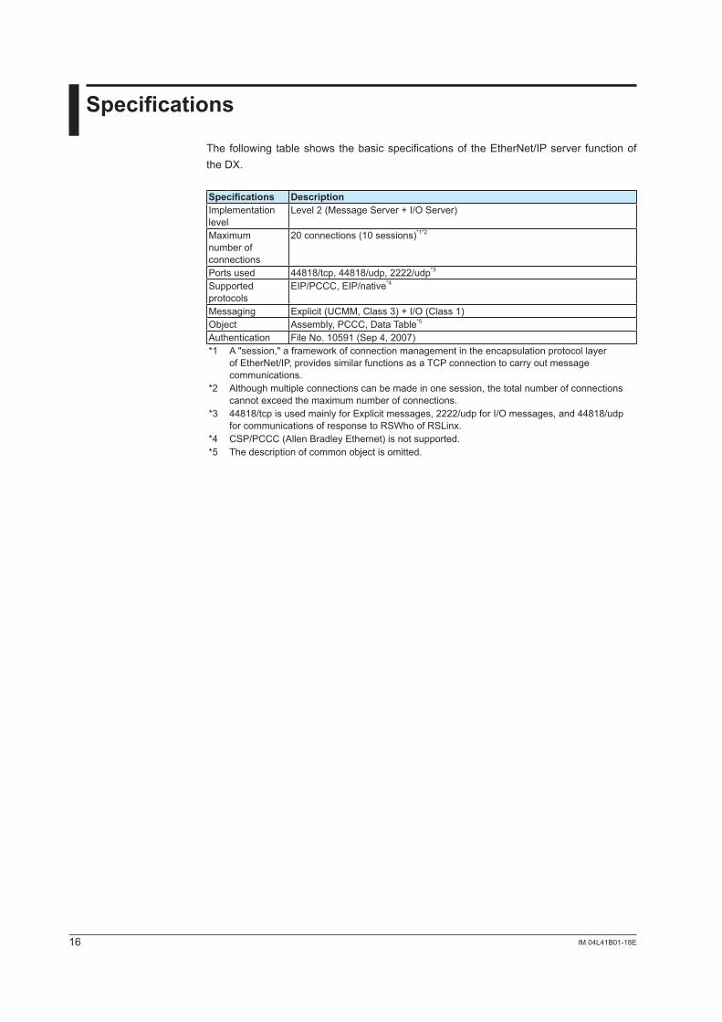
The following table shows the basic specificationsof theEtherNet/IPserver functionofthe DX.
Specifications DescriptionImplementation level
Level2(MessageServer+I/OServer)
Maximum number of connections
20 connections (�0 sessions)*�*2
Ports used 448�8/tcp, 448�8/udp, 2222/udp*�
Supported protocols
EIP/PCCC,EIP/native*4
Messaging Explicit(UCMM,Class3)+I/O(Class1)Object Assembly,PCCC,DataTable*5
Authentication FileNo.10591(Sep4,2007)*� A"session,"aframeworkofconnectionmanagementintheencapsulationprotocollayer
ofEtherNet/IP,providessimilarfunctionsasaTCPconnectiontocarryoutmessagecommunications.
*2 Althoughmultipleconnectionscanbemadeinonesession,thetotalnumberofconnectionscannot exceed the maximum number of connections.
*� 44818/tcpisusedmainlyforExplicitmessages,2222/udpforI/Omessages,and44818/udpforcommunicationsofresponsetoRSWhoofRSLinx.
*4 CSP/PCCC(AllenBradleyEthernet)isnotsupported.*5 Thedescriptionofcommonobjectisomitted.
�7IM 04L4�B0�-�8E
Example of an Explicit Message Using RSLogix 5000
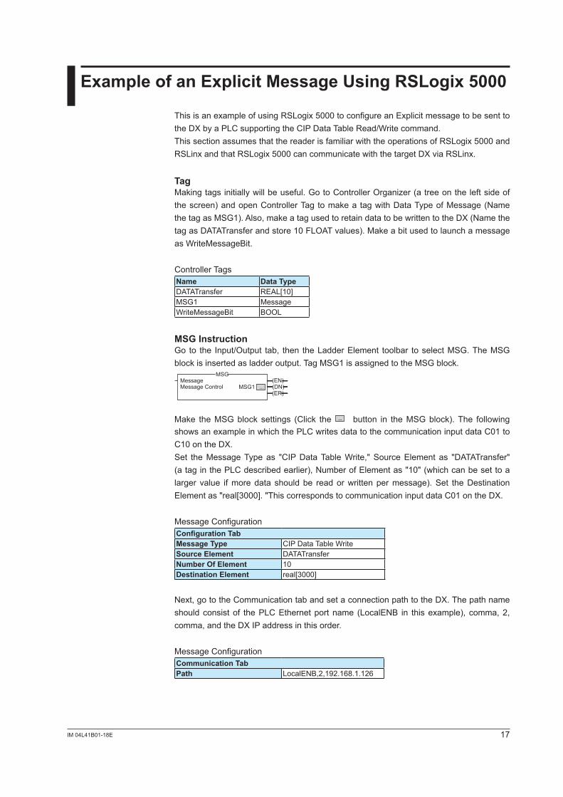
This is an exampleofusingRSLogix5000toconfigureanExplicitmessagetobesenttotheDXbyaPLCsupportingtheCIPDataTableRead/Writecommand.ThissectionassumesthatthereaderisfamiliarwiththeoperationsofRSLogix5000andRSLinx and that RSLogix5000cancommunicatewiththetargetDXviaRSLinx.
TagMakingtagsinitiallywillbeuseful.GotoControllerOrganizer(atreeontheleftsideofthescreen)andopenControllerTagtomakea tagwithDataTypeofMessage(NamethetagasMSG1).Also,makeatagusedtoretaindatatobewrittentotheDX(NamethetagasDATATransferandstore10FLOATvalues).MakeabitusedtolaunchamessageasWriteMessageBit.
ControllerTagsName Data TypeDATATransfer REAL[10]MSG� MessageWriteMessageBit BOOL
MSG InstructionGo to the Input/Output tab, then theLadderElement toolbar toselectMSG.TheMSGblock is inserted as ladder output. Tag MSG� is assigned to the MSG block.
MSG
MSG1(EN)
Message ControlMessage
(DN)(ER)
...
Make theMSGblock settings (Click the ... button in the MSG block). The following showsanexampleinwhichthePLCwritesdatatothecommunicationinputdataC01toC10ontheDX.Set theMessageTypeas "CIPDataTableWrite,"SourceElement as "DATATransfer"(ataginthePLCdescribedearlier),NumberofElementas"10"(whichcanbesettoalarger value ifmoredata shouldbe readorwrittenpermessage).Set theDestinationElementas"real[3000]."ThiscorrespondstocommunicationinputdataC01ontheDX.
MessageConfigurationConfiguration TabMessage Type CIPDataTableWriteSource Element DATATransferNumber Of Element �0Destination Element real[�000]
Next,gototheCommunicationtabandsetaconnectionpathtotheDX.Thepathnameshouldconsistof thePLCEthernetportname (LocalENB in thisexample), comma,2,comma, and the DX IP address in this order.
MessageConfigurationCommunication TabPath LocalENB,2,192.168.1.126
�8 IM 04L4�B0�-�8E
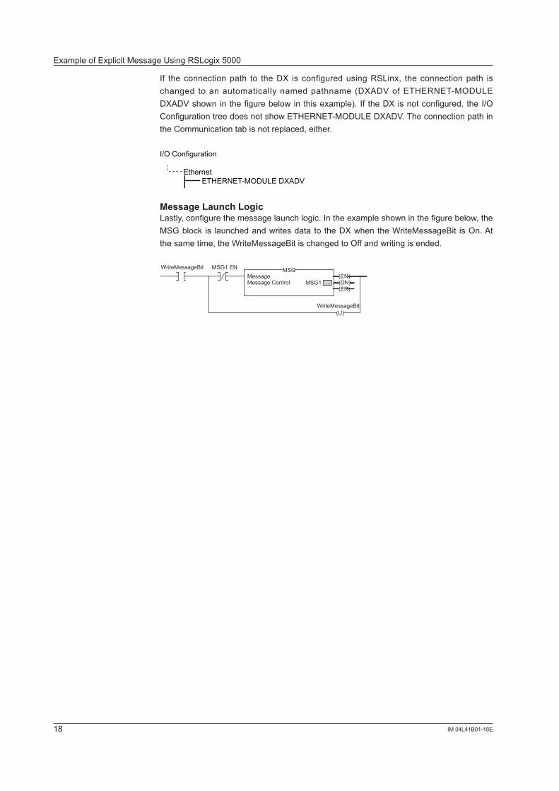
If the connection path to the DX is configured using RSLinx, the connection path is changed to anautomatically namedpathname (DXADVofETHERNET-MODULEDXADVshowninthefigurebelowinthisexample). If theDXisnotconfigured,theI/OConfigurationtreedoesnotshowETHERNET-MODULEDXADV.TheconnectionpathintheCommunicationtabisnotreplaced,either.
I/O Configuration
Ethernet ETHERNET-MODULE DXADV
Message Launch LogicLastly, configure the message launch logic. In the example shown in the figure below, the MSGblock is launchedandwritesdatatotheDXwhentheWriteMessageBit isOn.Atthesametime,theWriteMessageBitischangedtoOffandwritingisended.
MSG
(U)
MSG1(EN)
Message ControlMessage
WriteMessageBit MSG1 EN
WriteMessageBit
(DN)(ER)
...
ExampleofExplicitMessageUsingRSLogix5000
�9IM 04L4�B0�-�8E
Example of I/O Message Using RSLogix 5000
Connection with DXFirst,define theconnectionwithDXusingRSLinx.Go toCommunicationon themenubarandselectConfigureDrivers.
Next,selectEthernetDevicesandclickAddNew....
Enteradrivername. In thisexample,DXADV isenteredbutothernamescanalsobeentered.
EntertheIPaddressofDXandclickOK.
DXisdisplayedontheRSWholistofRSLinx.
Configuration of Communication SettingsOpenRSLogix5000and select aPLCused to communicatewithDX.Right-clickEthernetinI/OConfigurationandselectNewModule.
Click+ to open the list.SelectETHERNET-MODULEand clickOK.AnETHERNET-MODULEsetupwindowwillopen.
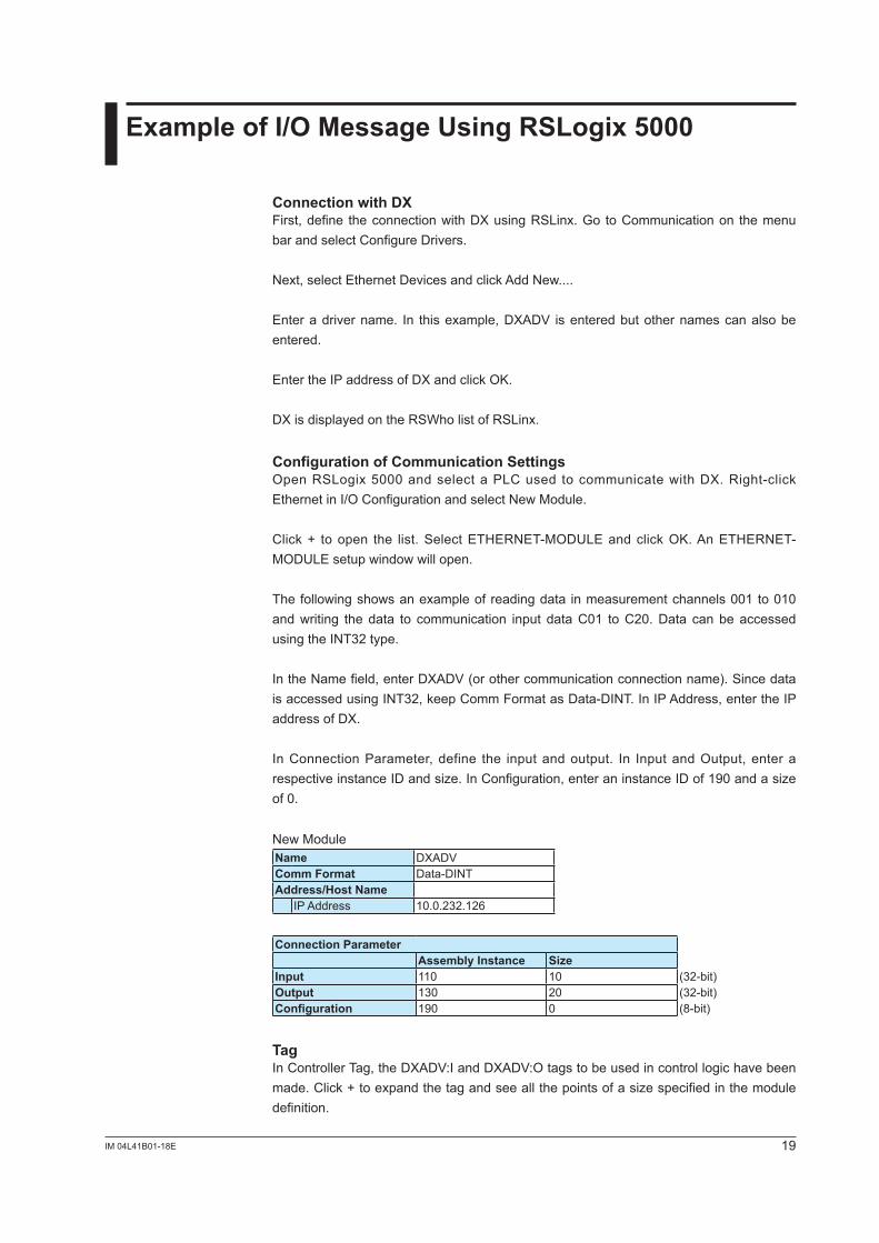
The following shows an example of reading data in measurement channels 00� to 0�0 andwriting thedata to communication input dataC01 toC20.Data canbeaccessedusing the INT�2 type.
IntheNamefield,enterDXADV(orothercommunicationconnectionname).SincedataisaccessedusingINT32,keepCommFormatasData-DINT.InIPAddress,entertheIPaddress of DX.
InConnectionParameter, define the input andoutput. In Input andOutput, enter arespectiveinstanceIDandsize.InConfiguration,enteraninstanceIDof190andasizeof 0.
New ModuleName DXADVComm Format Data-DINTAddress/Host Name
IPAddress 10.0.232.126
Connection ParameterAssembly Instance Size
Input ��0 �0 (�2-bit)Output ��0 20 (�2-bit)Configuration �90 0 (8-bit)
TagInControllerTag,theDXADV:IandDXADV:Otagstobeusedincontrollogichavebeenmade.Click+toexpandthetagandseeallthepointsofasizespecifiedinthemoduledefinition.
Index
Aadapter .......................................................................................5assemblyobject ........................................................................��
Bbasic setting mode......................................................................7
Ccable connection.........................................................................7CIPDataTableRead/Write.......................................................�7client ...........................................................................................5commands ..................................................................................9CommonIndustrialProtocol .......................................................5communication input data............................................. 9, �0, ��communicationinterval .............................................................�4computation channel .................................................... 9, �0, ��configuration components ..........................................................5configuration tool ........................................................................5consumer ..................................................................................��
Ddata type ............................................................................�2, �4data update...............................................................................�4deviceprofile ..............................................................................8DF� communications ..................................................................6DNS ............................................................................................7DX features.................................................................................6DX settings .................................................................................6
EEDS file.......................................................................................8EtherNet/IPserver ......................................................................7Ethernet port ...............................................................................7Explicit message.........................................................................9Explicit message example ........................................................�7external input channel .................................................. 9, �0, ��
Hhost information ..........................................................................7
II/Omessage .............................................................................��i/o message ..............................................................................��Implicit message .......................................................................��installation...................................................................................8instance ID................................................................................��IP address ..................................................................................7
Mmeasurement channel .................................................. 9, �0, ��message .....................................................................................6message launch logic ...............................................................�8MSG instruction ...................................................................9, �7
Nnon-existent data, accessing ....................................................�4
PPCCC .........................................................................................6
PLC2UnprotectedRead/Write ...................................................9PLC5WordRangeRead/Write ................................................�0producer ...................................................................................��programmable logic controller ....................................................�
RRSLinx ......................................................................................�7RSLogix5000 ...........................................................................�7
Sscanner .......................................................................................5server.....................................................................................5, 7SLCTypedRead/Write .............................................................�0specifications ............................................................................�6symbols (used in the manual).....................................................2system configuration...................................................................9
Ttag.............................................................................................�7
Index
20 IM 04L41B01-18E