user s manual - elhvb€¦ · 8 asus p4t-f user’s manual performance tures 2.1 the asus p4t-f the...
TRANSCRIPT

ASUS P4T-F User’s Manual 1
®
P4T-F
Intel® 850 ATX Motherboard
USER’S MANUAL

2 ASUS P4T-F User’s Manual
USER'S NOTICE
Product Name: ASUS P4T-F
Manual Revision: 1.01 E804
Release Date: August 2001
No part of this manual, including the products and software described in it, may be repro-duced, transmitted, transcribed, stored in a retrieval system, or translated into any language inany form or by any means, except documentation kept by the purchaser for backup purposes,without the express written permission of ASUSTeK COMPUTER INC. (“ASUS”).
ASUS PROVIDES THIS MANUAL “AS IS” WITHOUT WARRANTY OF ANY KIND,EITHER EXPRESS OR IMPLIED, INCLUDING BUT NOT LIMITED TO THE IMPLIEDWARRANTIES OR CONDITIONS OF MERCHANTABILITY OR FITNESS FOR A PAR-TICULAR PURPOSE. IN NO EVENT SHALL ASUS, ITS DIRECTORS, OFFICERS,EMPLOYEES OR AGENTS BE LIABLE FOR ANY INDIRECT, SPECIAL, INCIDEN-TAL, OR CONSEQUENTIAL DAMAGES (INCLUDING DAMAGES FOR LOSS OFPROFITS, LOSS OF BUSINESS, LOSS OF USE OR DATA, INTERRUPTION OF BUSI-NESS AND THE LIKE), EVEN IF ASUS HAS BEEN ADVISED OF THE POSSIBILITYOF SUCH DAMAGES ARISING FROM ANY DEFECT OR ERROR IN THIS MANUALOR PRODUCT.
Product warranty or service will not be extended if: (1) the product is repaired, modified oraltered, unless such repair, modification of alteration is authorized in writing by ASUS; or (2)the serial number of the product is defaced or missing.
Products and corporate names appearing in this manual may or may not be registered trade-marks or copyrights of their respective companies, and are used only for identification orexplanation and to the owners’ benefit, without intent to infringe.
• Adobe and Acrobat are registered trademarks of Adobe Systems Incorporated.• Intel, LANDesk, and Pentium are registered trademarks of Intel Corporation.• Trend and ChipAwayVirus are trademarks of Trend Micro, Inc.• Windows and MS-DOS are registered trademarks of Microsoft Corporation.
The product name and revision number are both printed on the product itself. Manual revi-sions are released for each product design represented by the digit before and after the periodof the manual revision number. Manual updates are represented by the third digit in the manualrevision number.
For previous or updated manuals, BIOS, drivers, or product release information, contact ASUSat http://www.asus.com.tw or through any of the means indicated on the following page.
SPECIFICATIONS AND INFORMATION CONTAINED IN THIS MANUAL ARE FUR-NISHED FOR INFORMATIONAL USE ONLY, AND ARE SUBJECT TO CHANGE ATANY TIME WITHOUT NOTICE, AND SHOULD NOT BE CONSTRUED AS A COM-MITMENT BY ASUS. ASUS ASSUMES NO RESPONSIBILITY OR LIABILITY FORANY ERRORS OR INACCURACIES THAT MAY APPEAR IN THIS MANUAL, INCLUD-ING THE PRODUCTS AND SOFTWARE DESCRIBED IN IT.
Copyright © 2001 ASUSTeK COMPUTER INC. All Rights Reserved.

ASUS P4T-F User’s Manual 3
ASUS CONTACT INFORMATIONASUSTeK COMPUTER INC. (Asia-Pacific)MarketingAddress: 150 Li-Te Road, Peitou, Taipei, Taiwan 112Telephone: +886-2-2894-3447Fax: +886-2-2894-3449Email: [email protected]
Technical SupportMB/Others (Tel): +886-2-2890-7121 (English)Notebook (Tel): +886-2-2890-7122 (English)Desktop/Server (Tel):+886-2-2890-7123 (English)Fax: +886-2-2893-7775Email: [email protected]: www.asus.com.twFTP: ftp.asus.com.tw/pub/ASUS
ASUS COMPUTER INTERNATIONAL (America)MarketingAddress: 6737 Mowry Avenue, Mowry Business Center, Building 2
Newark, CA 94560, USAFax: +1-510-608-4555Email: [email protected]
Technical SupportFax: +1-510-608-4555Email: [email protected]: www.asus.comFTP: ftp.asus.com/Pub/ASUS
ASUS COMPUTER GmbH (Europe)MarketingAddress: Harkortstr. 25, 40880 Ratingen, BRD, GermanyFax: +49-2102-442066Email: [email protected] (for marketing requests only)
Technical SupportHotline: MB/Others: +49-2102-9599-0 Notebook: +49-2102-9599-10Fax: +49-2102-9599-11Support (Email): www.asuscom.de/de/support (for online support)WWW: www.asuscom.deFTP: ftp.asuscom.de/pub/ASUSCOM

4 ASUS P4T-F User’s Manual
CONTENTS
1. INTRODUCTION ............................................................................. 7
1.1 How This Manual Is Organized .................................................. 71.2 Item Checklist ............................................................................. 7
2. FEATURES ........................................................................................ 8
2.1 The ASUS P4T-F ........................................................................ 82.2 P4T-F Motherboard Components .............................................. 12
3. HARDWARE SETUP ...................................................................... 14
3.1 P4T-F Motherboard Layout ...................................................... 143.2 Layout Contents ........................................................................ 153.3 Hardware Setup Procedure ....................................................... 163.4 Motherboard Settings ................................................................ 173.5 System Memory ........................................................................ 233.6 Central Processing Unit (CPU) ................................................. 253.7 Expansion Cards ....................................................................... 283.8 External Connectors .................................................................. 323.9 Starting Up the First Time ........................................................ 43
4. BIOS SETUP ..................................................................................... 45
4.1 Managing and Updating Your BIOS ......................................... 454.1.1 Upon First Use of the Computer System ....................... 454.1.2 Updating BIOS Procedures ........................................... 46
4.2 BIOS Setup Program ................................................................ 494.2.1 BIOS Menu Bar ............................................................. 504.2.2 Legend Bar .................................................................... 50
4.3 Main Menu ................................................................................ 524.3.1 Primary & Secondary Master/Slave .............................. 534.3.2 Keyboard Features ......................................................... 56
4.4 Advanced Menu ........................................................................ 584.4.1 Chip Configuration ........................................................ 614.4.2 I/O Device Configuration .............................................. 634.4.3 PCI Configuration ......................................................... 654.4.4 Shadow Configuration ................................................... 67
4.5 Power Menu .............................................................................. 684.5.1 Power Up Control .......................................................... 704.5.2 Hardware Monitor ......................................................... 71
4.6 Boot Menu ................................................................................ 724.7 Exit Menu ................................................................................. 74

ASUS P4T-F User’s Manual 5
CONTENTS5. SOFTWARE SETUP ....................................................................... 77
5.1 Install Operating System ........................................................... 775.2 Start Windows ........................................................................... 775.3 P4T-F Motherboard Support CD............................................... 78
6. SOFTWARE REFERENCE ........................................................... 81
6.1 ASUS PC Probe ........................................................................ 816.2 ASUS Live Update ................................................................... 866.3 CyberLink PowerPlayer SE ...................................................... 876.4 CyberLink VideoLive Mail ....................................................... 88
7. APPENDIX ....................................................................................... 91
7.1 Glossary .................................................................................... 91
INDEX ................................................................................................... 95

6 ASUS P4T-F User’s Manual
FCC & DOC COMPLIANCEThis device complies with FCC Rules Part 15. Operation is subject to the followingtwo conditions:
• This device may not cause harmful interference, and• This device must accept any interference received, including interference that
may cause undesired operation.
This equipment has been tested and found to comply with the limits for a Class Bdigital device, pursuant to Part 15 of the FCC Rules. These limits are designed toprovide reasonable protection against harmful interference in a residential installa-tion. This equipment generates, uses and can radiate radio frequency energy and, ifnot installed and used in accordance with manufacturer's instructions, may causeharmful interference to radio communications. However, there is no guarantee thatinterference will not occur in a particular installation. If this equipment does causeharmful interference to radio or television reception, which can be determined byturning the equipment off and on, the user is encouraged to try to correct the interfer-ence by one or more of the following measures:
• Re-orient or relocate the receiving antenna.• Increase the separation between the equipment and receiver.• Connect the equipment to an outlet on a circuit different from that to which the
receiver is connected.• Consult the dealer or an experienced radio/TV technician for help.
WARNING! Any changes or modifications to this product not expressly ap-proved by the manufacturer could void any assurances of safety or performanceand could result in violation of Part 15 of the FCC Rules.
Reprinted from the Code of Federal Regulations #47, part 15.193, 1993. Washington DC: Office of the
Federal Register, National Archives and Records Administration, U.S. Government Printing Office.
Canadian Department of Communications StatementThis digital apparatus does not exceed the Class B limits for radio noise emissionsfrom digital apparatus set out in the Radio Interference Regulations of the CanadianDepartment of Communications.
This Class B digital apparatus complies with Canadian ICES-003.
Cet appareil numérique de la classe B est conforme à la norme NMB-003 du Canada.

ASUS P4T-F User’s Manual 7
1.1 How This Manual Is OrganizedThis manual is divided into the following sections:
1. INTRODUCTION Manual information and checklist2. FEATURES Production information and specifications3. HARDWARE SETUP Intructions on setting up the motherboard.4. BIOS SETUP Intructions on setting up the BIOS5. SOFTWARE SETUP Intructions on setting up the included software6. SOFTWARE REFERENCE Reference material for the included software7. APPENDIX Optional items and general reference
1.2 Item ChecklistCheck that your package is complete. If you discover damaged or missing items,contact your retailer.
1. INTRODUCTION
1. IN
TRO
DU
CTI
ON
Man
ual /
Che
cklis
t
Package Contents(1) ASUS Motherboard(1) 40-pin 80-conductor ribbon
cable for internal UltraDMA33/66/100 IDE drives
(1) Ribbon cable for (1) 5.25” and (2)3.5” floppy disk drives
(1) COM Port Bracket and Cable(1) ASUS 2-port USB connector set
with bracket(1) I/O port bracket(1) Bag of spare jumpers(1) Support drivers and utilities(1) This Motherboard User’s Manual(1) CPU Retention Module(1) CD Audio(1) Quick Setup Guide(1) Reference Card(2) ASUS C-RIMM Continuity
RIMM
Optional ItemsASUS IrDA-compliant infraredmoduleRambusLAN Card1394 Card

8 ASUS P4T-F User’s Manual
Performance
2. FEATU
RE
S
2.1 The ASUS P4T-FThe ASUS P4T-F motherboard is carefully designed for the demanding PC userwho wants advanced features processed by the fastest processors.
2.1.1 Specifications• Intel Processor Support: Intel Socket 423 Pentium® 4 processors, 1.3 to 1.8
GHz and higher.• Intel 850 Chipset: Features the Intel® 850 chipset (82850 Tehama Memory Con-
troller Hub, I/O Controller and Firmware Hub) with support for AGP 4X ProMode, (1.5 volt only); 400MHz Front Side Bus (FSB); and dual channel RDRAM.
• Intel ICH2: The Intel I/O Controller Hub 2 (82801 ICH2) features support forUltraDMA/100, which allows burst mode data transfer rates of up to 100MB/sec; and two USB controllers for a total of 4 USB ports.
• PC800 Memory Support: Equipped with four Rambus Inline Memory Module(RIMM) sockets to support Intel PC800/PC600-compliant Rambus DRAMs(RDRAMs) (available in 64, 96, 128, 192, 256, 512MB) up to 2GB. TheseRDRAMs are necessary to meet the increase in processor performance andmultimedia and 3D functions, especially where high bandwidth is required.
• Intel® Accelerated Hub Architecture: Features a dedicated high speed hublink between the ICH2 and MCH with a bandwidth of 266MB/sec – twice themaximum bandwidth of the PCI bus.
• AGP Pro Slot: Comes with an Accelerated Graphics Port Pro slot thatsupports AGP cards for high performance, component level interconnecttargeted at 3D graphical applications using a 4X mode bus. The slot is keyed tosupport only the latest 1.5 volt AGP cards: i.e.: ASUS V3800 and newerversions.
• JumperFree™ Mode: Now processor settings and easy overclocking offrequency and Vcore voltage can be controlled through the BIOS firmware ifJumperFree™ mode is enabled.
• Easy-to-Use DIP Switches: As an alternative to JumperFree Mode™, jumpersand DSW switches are included to allow manual adjustment of the processor’sexternal frequency.
• UltraDMA/100 Support: Comes with an onboard PCI Bus Master IDE controllerwith two connectors that support four IDE devices on two channels. SupportsUltraDMA/100, UltraDMA/66, UltraDMA/33, PIO Modes 3 & 4 and Bus MasterIDE DMA Mode 2, and Enhanced IDE devices, such as DVD-ROM, CD-ROM,CD-R/RW, LS-120, and Tape Backup drives.
• More USB Ports: Supports a total of 4 USB ports for exceptiona peripheralconnectivity options.
2. FEATURES

ASUS P4T-F User’s Manual 9
2. FEATURES• CNR Support: A Communication and Networking Riser (CNR) slot provides
an interface to support very affordable multichannel audio, V.90 analog modem,Home PNA, 10/100 Ethernet networking, and a USB hub.
• PC Health Monitoring: An easy way to examine and manage system statusinformation, such as CPU and systerm voltages, temperatures, and fan statusthrough the onboard hardware and the bundled ASUS PC Probe or Intel LDCMsoftware.
• Legacy Free: Provides five 32-bit PCI (PCI 2.2 compliant) with no ISA,eliminating bottlenecks and system memory management issues. All PCI slotscan support Bus Master PCI cards, such as SCSI or LAN cards. (PCI supports upto 133MB/s maximum throughput.)
• Low Pin Count (LPC) Super Multi-I/O: Provides two high-speed UARTompatible serial ports and one parallel port with EPP and ECP capabilities.UART2 can also be directed from COM2 to the Infrared Module for wirelessconnections.
• Enhanced ACPI & Anti-Boot Virus Protection: Programmable BIOS (FlashEEPROM), offering enhanced ACPI for Windows 98/2000/Millenium compat-ibility, built-in firmware-based virus protection, and autodetection of most de-vices for virtually automatic setup.
• Smart BIOS: 2Mbit firmware gives a new easy-to-use interface for morecontrol and protection for the motherboard. Supports Vcore and CPU/RDRAMfrequency adjustments, boot block write protection, and HD/SCSI/MO/ZIP/CD/Floppy boot selection.
• IrDA: Supports an optional infrared port module for a wireless interface.• Concurrent PCI: Concurrent PCI allows multiple PCI transfers from PCI
master bus to the memory and processor.• Onboard LED: Signals AC power is okay.
• Desktop Management Interface (DMI): Supports DMI through BIOS, whichallows hardware to communicate within a standard protocol creating a higherlevel of compatibility. (Requires DMI-enabled components.)
2.1.2 Optional Components• AC’97 Codec: The latest high-performance mini-chipset supports hi-fidelity
18-bit stereo, full duplex audio performance. The chipset supporst up to fouranalog line inputs, two stereo outputs, and one mono output channel. Addedfeatuers include 3D stereo enhancement, and extra true line-level out for head-phones and speaker amplifiers.
• Auxillary Power Connector: Extra power back-up available with this 6 toothconnector.
2. F
EAT
UR
ES
Opt
iona
l Com
pone
nts

10 ASUS P4T-F User’s Manual
2. FEATURES2.1.3 Performance Features• High-Speed Data Transfer Interface: Onboard IDE Bus Master controller with
two connectors that support four IDE devices in two channels. SupportsUltraDMA/100/66, UltraDMA/33 (IDE DMA Mode 2), PIO Modes 3 & 4, andsupports Enhanced IDE devices, such as DVD-ROM, CD-ROM, CD-R/RW,LS-120, and Tape Backup drives. UltraDMA/100 is backward compatible withDMA/66, DMA/33, and DMA and with existing DMA devices and systems sothere is no need to upgrade current EIDE/IDE drives and host systems.(UltraDMA/66/100 requires a 40-pin 80-conductor cable to be enabled.)
• RDRAM Optimized Performance: This motherboard supports RambusDynamic Random Access Memory (RDRAM). While PC100 SDRAM modulesoperate at 100MHz with a peak bandwidth of 0.8GB/s, MCH dual channel RambusDRAMs can operate at up to 400MHz with a peak bandwidth of 3.2GB/s.
• ACPI Ready: ACPI (Advanced Configuration and Power Interface) is alsoimplemented on all ASUS smart series motherboards. ACPI provides moreEnergy Saving Features for future operating systems (OS) supporting OS DirectPower Management (OSPM) functionality. With these features implemented inthe OS, PCs can be ready around the clock, yet satisfy all the energy savingstandards. To realize the benefits of ACPI, an ACPI-supported OS, such asWindows 98/2000/Millenium, must be used.
• Suspend and Go: Suspend-to-RAM (STR) provides maximum power savingsas an alternative to leaving the computer ON and QuickStart™ so that you donot have to wait for a long time for system bootup.
• New Compliancy: Both the BIOS and hardware levels of the motherboard meetthe stringent requirements for PC 99 certification. The new PC 99 requirementsfor systems and components are based on the following high-level goals: sup-port for Plug and Play compatibility and power management for configuringand managing all system components, and 32-bit device drivers and installationprocedures for Windows 95/NT and later. Color-coded connectors and descrip-tive icons make identification easy as required by PC 99.
Specifications2. FE
ATUR
ES

ASUS P4T-F User’s Manual 11
2. FEATURES
2. F
EAT
UR
ES
Inte
lligen
ce
2.1.4 Intelligence• Auto CPU Throttling Function: Incorporated into this motherboard is a new
technology to enable Pentium 4 processors auto throttling function. When autothrottling is enabled, the CPU with throttle down to 50% of its duty cycle whenthe CPU temperature reaches the threshold and return to 100% of its duty cyclewhen temperature lowers to normal level. This function ensures the bestperformance and reliability.
• Fan Status Monitoring and Alarm: To prevent system overheat and systemdamage, the CPU, MAIN, and PCI fans can be monitored for RPM and failure.All the fans are set for its normal RPM range and alarm thresholds.
• Temperature Monitoring and Alert: To prevent system overheat and system dam-age, this motherboard supports processor thermal sensing and auto-protection.
• Voltage Monitoring and Alert: System voltage levels are monitored to ensurestable current to critical motherboard components. Voltage specifications aremore critical for future processors, so monitoring is necessary to ensure propersystem configuration and management.
• System Resources Alert: Today’s operating systems, such as Windows 98/Millenium, and Windows NT/2000, require much more memory and hard drivespace to present enormous user interfaces and run large applications. The onboardhardware ASUS ASIC in conjunction with either the bundled ASUS PC Probeor Intel LDCM will warn the user before the system resources are used up toprevent possible application crashes. Suggestions will give the user informationon managing their limited resources more efficiently.
• Dual Function Power Button: Through BIOS, the power button can be definedas the “Stand by” (ie.: Suspend or Sleep) button or as the Soft-Off (see ATXPower / Soft-Off Switch Lead in 3.8 Connectors for more information) button.Regardless of the setting, pushing the power button for more than 4 seconds willenter the Soft-Off mode.
• Peripheral Power Up: Keyboard or Mouse power up can be enabled or dis-abled through BIOS setup to allow the computer to be powered ON using yourkeyboard or mouse click.

12 ASUS P4T-F User’s Manual
2. FEATURES2.2 P4T-F Motherboard ComponentsSee opposite page for locations.
Location
Processor Support Socket 423 for Pentium 4 Processors ....................................... 2
Chipsets Intel 850 Memory Controller Hub (MCH) ............................... 4Intel I/O Controller Hub 2 (ICH2) ......................................... 112Mbit Firmware Hub (FWH) ................................................. 13Low Pin Count (LPC) Super Multi-I/O Chipset .................... 16
Main Memory Maximum 1GB support4 RIMM Sockets ...................................................................... 5Dual Channel PC800/PC600 RDRAM support
Switches DSW Frequency Setting ........................................................... 9
Expansion Slots 5 PCI Slots .............................................................................. 171 Accelerated Graphics Port (AGP Pro) Slot .......................... 20Communictions Network Riser (CNR) .................................. 15
System I/O 2 IDE Connectors (UltraDMA33/66/100 support) ................... 71 Floppy Disk Drive Connector ............................................... 81 USB Header (supports 2 USB ports) ................................... 121 Parallel Port Connector ............................................. (Top) 241 Serial COM1 Port Connector .............................. (Bottom) 251 Serial COM2 Port Connector .............................. (Bottom) 232 USB Port Connectors ......................................................... 261 PS/2 Mouse Connector .............................................. (Top) 271 PS/2 Keyboard Connector ................................... (Bottom) 27
Audio Headphone Connector ............................................................ 18AC’97 Audio CODEC ............................................................ 19Microphone 2 Connector ........................................................ 211 Game/MIDI Connector .............................................. (Top) 221 Line Out Connector ............................................. (Bottom) 221 Line In Connector ................................................ (Bottom) 221 Line Microphone Connector ............................... (Bottom) 22
Hardware Monitoring ASUS onboard chipset ........................................................... 10
Power ATX Power Supply Connector ................................................. 1ATX 12V Power Supply Connector ......................................... 3
Special Feature Auxillary Power Connector ...................................................... 6Onboard LED ......................................................................... 14
Form Factor ATX
2. FEATU
RE
SM
B Components

ASUS P4T-F User’s Manual 13
2. FEATURES
2. F
EAT
UR
ES
Com
pone
nt L
ocat
ions
2.2.1 Component Locations
2
14 813
17
20
12
24
25
26
27
22
5
11
74 6
10 9
1 3
15
16
19
23
18
21

14 ASUS P4T-F User’s Manual
3. HARDWARE SETUP3.1 P4T-F Motherboard Layout
Grayed components are available only on certain models at the time of purchase.
Motherboard Layout3. H
/W S
ETU
P
24.4cm (9.60in)
30.5
cm (
12.0
in)
PS/2KBMST: MouseB: Keyboard
MAIN_FAN
CHASSIS PANEL
FLOPPY
SE
CO
ND
AR
Y ID
EP
RIM
AR
Y ID
E
Intel I/OController
Hub(ICH2)
P4T-FPCI_FAN
DIPSwitches
LED
Accelerated Graphics Port (AGP Pro)
ASUSASICwith
HardwareMonitor
CR2032 3VLithium Cell
CMOS Power
CLRTC
Socket 423
USBT: Port1B: Port2
COM1
PAR
AL
LE
L P
OR
T
COM2Intel 850Memory
ControllerHub (MCH)
ATX Power Connector
2MbitFirmware
Hub
USB2
RIM
MA
1 (1
6/18
bit,
184
-pin
mod
ule)
SuperI/O
AU
X P
ower
Con
nect
or
CPU_FAN
ATX12V
USBPWR
JEN
IR
PCI1
PCI2
PCI3
PCI4
PCI5
RIM
MA
2 (1
6/18
bit,
184
-pin
mod
ule)RIMMB2 (16/18 bit, 184-pin module)
RIMMB1 (16/18 bit, 184-pin module)
CNR_SLOT
J3-
ADN
J3+
OC3
AUX
MODEM
MIC2
HEADPHONE
GA
ME
_AU
DIO
MicIn
LineOut
LineIn
AudioCodec
CD1
HDDLED

15
3. HARDWARE SETUP
ASUS P4T-F User’s Manual
3.2 Layout ContentsMotherboard Settings 1) JEN p. 18 JumperFree™ Mode (JEN) (Disable / Enable) 2) SW1 (Switches 6-10) p. 19 CPU Ext. Freq. Selection (SW1 Switches 1–5) 3) SW1 (Switches 1-4) p. 20 Manual CPU Ratio Settings (SW1 Switches 7-10) 4) USBPWR p. 21 USB Device Wake-up (USBPWR) 5) ADN p. 22 Onboard Audio Codec (Enable/Disable) 6) J3-J3-/OC3 p. 22 USB2 / CNRUSB SelectionMemory, CPU and Expansion
1) RIMMA1/A2/B1/B2 p.23 184-Pin System Memory Support2) CPU p.25 Central Processing Unit (CPU)3) Heatsink p.26 CPU Heatsink Retention Module Installation4) PCI1/2/3/4/5 p.28 32-bit PCI Bus Expansion Slots5) AGP Pro p.30 Accelerated Graphics Port (AGP Pro) Slot6) CNR p.31 Communications and Networking Riser (CNR) Slot
Connectors
1) PS2KBMS p.32 PS/2 Mouse Connector (6 pin female)2) PS2KBMS p.32 PS/2 Keyboard Connector (6 pin female)3) PRINTER p.33 Parallel Port Connector (25 pin female)4) COM1, COM2 p.33 Serial Port Connector (Two 9 pin male)5) USB p.33 Universal Serial Bus Ports (Two 4 pin female)6) GAME_AUDIO p.34 Joystick/MIDI Connector (15 pin female) (optional)7) LINE-IN, -OUT, MIC p.34 Audio Port Connectors (Three 1/8” female)(optional)8) FLOPPY p.34 Floppy Disk Drive Connector (34-1pin)9) PRIMARY/SECONDARY IDE p.35 Primary/Secondary IDE Connectors (Two 40-1 pin)
10) MAIN_FAN, CPU_FAN p.36 Fan Connectors (Three 3 pin)PCI_FAN
11) USB2 p.37 USB Header (10-1 pin)12) MODEM, CD_IN, AUX p.37 Internal Audio Connectors (Three 4 pin) (optional)13) MIC2 p.38 Internal Microphone Connector (3 pin) (optional)14) HEADPHONE p.38 Headphone Connector (3 pin) (optional)15) IR p.39 Standard Infrared (SIR) Module Connector (5 pin)16) HDLED p.39 IDE Activity LED (2 pin)17) ATXPWR, ATX12V, (AUXPWR) p.40 Power Supply Connector (20 pin, 4 pin) (6 pin)18) PWRLED (PANEL) p.41 System Power LED Lead (3-1 pin)19) KEYLOCK (PANEL) p.41 Keyboard Lock Switch Lead (2 pin)20) SPEAKER (PANEL) p.41 System Warning Speaker Connector (4 pin)21) MSG.LED (PANEL) p.41 System Message LED (2 pin)22) SMI (PANEL) p.41 System Management Interrupt Switch Lead (2 pin)23) PWRSW (PANEL) p.41 ATX Power / Soft-Off Switch Lead (2 pin)24) RESET (PANEL) p.41 Reset Switch Lead (2 pin)
Layo
ut C
onte
nts
3. H
/W S
ETU
P

16 ASUS P4T-F User’s Manual
3. HARDWARE SETUP
Getting Started
3. H/W
SE
TUP
3.3 Hardware Setup ProcedureIMPORTANT: Due to Pentium 4 CPU’s power consumption requirement, anATX12V power supply is recommended for this motherboard. For typical systemconfigurations, an ATX12V power supply that can supply at least 230W and at least8.5A on the +12V lead is required. For heavily-loaded configurations, an ATX12Vpower supply that can supply at least 300W is required.
Complete the following steps before using your computer:
1. Check motherboard settings2. Install memory modules3. Install the Central Processing Unit (CPU)4. Install Expansion Cards5. Connect ribbon cables, panel wires, and power supply cables6. Configure the BIOS parameter settings
WARNING! Make sure that you unplug your power supply when adding orremoving system components. Failure to do so may cause severe damage toyour motherboard, peripherals, and/or components.

17
3. HARDWARE SETUP
ASUS P4T-F User’s Manual
Mot
herb
oard
Set
tings
3. H
/W S
ETU
P
3.4 Motherboard SettingsThis section tells you how to change motherboard function settings through theswitches and/or jumpers.
P4T-F
P4T-F Onboard LED
ON OFFStandbyPower
PoweredOff
WARNING! Computer motherboards and expansion cards contain very delicateIntegrated Circuit (IC) chips. To protect them against damage from static electric-ity, you should follow some precautions whenever you work on your computer.1. Unplug your computer when working on the inside.2. Use a grounded wrist strap before handling computer components. If you do
not have one, touch both of your hands to a safely grounded object or to a metalobject, such as the power supply case.
3. Hold components by the edges and try not to touch the IC chips, leads or con-nectors, or other components.
4. Place components on a grounded antistatic pad or on the bag that came with thecomponent whenever the components are separated from the system.
5. Ensure that the ATX power supply is switched off before you plug in orremove the ATX power connector on the motherboard.

18 ASUS P4T-F User’s Manual
3. HARDWARE SETUP
P4T-F
P4T-F DIP Switches
1. Frequency Multiple2. Frequency Multiple3. Frequency Multiple4. Frequency Multiple 5. Reserved
6. Frequency Selection7. Frequency Selection8. Frequency Selection9. Frequency Selection
10. Frequency Selection
OFF
ON
12
34
56
78
910
ON
SW1
P4T-F
Jumper Mode
1 2
P4T-F JumperFree™ Mode Setting
ON
12
34
56
78
910
JEN
Jumper Free(Default)
2 3
OFF
SW1
Motherboard Frequency Settings (SW1 Switches)The motherboard frequency is adjusted through the DIP switches. The white blockrepresents the switch’s position. The illustration below shows all the switches in theOFF position.
1) JumperFree™ Mode (JEN)This jumper allows you to enable or disable the JumperFree™ mode. TheJumperFree™ mode allows processor settings to be made through the BIOS setup(see 4.4 Advanced Menu).
Setting JENEnable (JumperFree) [2-3] (default)Disable (Jumper Mode) [1-2]
Motherboard Settings3. H
/W S
ETU
P

19
3. HARDWARE SETUP
ASUS P4T-F User’s Manual
2) CPU External Frequency Selection (SW1 Switches 6-10)This option tells the clock generator what frequency to send to the CPU, DRAM,and the PCI bus. This allows the selection of the CPU’s External frequency (orBUS Clock). The BUS Clock multiplied by the Frequency Multiple equals theCPU’s Internal frequency (the advertised CPU speed).
P4T-F
P4T-F CPUExternal Frequency Selection
CPUAGPPCI
SW1
100.0MHz66.0MHz33.0MHz
ON
12
34
56
78
910
103.0MHz68.0MHz34.0MHz
ON
12
34
56
78
910
105.0MHz70.0MHz35.0MHz
ON
12
34
56
78
910
110.0MHz73.0MHz36.0MHz
ON
12
34
56
78
910
Mot
herb
oard
Set
tings
3. H
/W S
ETU
P
WARNING! Set the CPU frequency only to the recommended settings.Frequencies other than the recommended CPU bus frequencies are not guaranteedto be stable. Overclocking the processor is not recommended. It may result in aslower speed.

20 ASUS P4T-F User’s Manual
3. HARDWARE SETUP
Motherboard Settings3. H
/W S
ETU
P
P4T-F
P4T-F CPU ExternalClock (BUS) FrequencySelection
SW1
8.0x
ON
1 2 3 4 5 6 7 8 9 10
ON
1 2 3 4 5 6 7 8 9 10
10.0x
ON
1 2 3 4 5 6 7 8 9 10
11.0x
ON
1 2 3 4 5 6 7 8 9 10
12.0x
13.0x
ON
1 2 3 4 5 6 7 8 9 10
14.0x
ON
1 2 3 4 5 6 7 8 9 10
15.0x
ON
1 2 3 4 5 6 7 8 9 10
16.0x
ON
1 2 3 4 5 6 7 8 9 10
17.0x
ON
1 2 3 4 5 6 7 8 9 10
ON
1 2 3 4 5 6 7 8 9 10
18.0x
ON
1 2 3 4 5 6 7 8 9 10
19.0x
ON
1 2 3 4 5 6 7 8 9 10
20.0x
21.0x
ON
1 2 3 4 5 6 7 8 9 10
22.0x
ON
1 2 3 4 5 6 7 8 9 10
23.0x
ON
1 2 3 4 5 6 7 8 9 10
24.0x
ON
1 2 3 4 5 6 7 8 9 10
3) Manual CPU Ratio Settings (SW1 Switches 1-4)Set SW1 switches (7-10) to use the clock multiplier to coordinate the ratio ofbus speeds with CPU settings. Set the DSW switches according to the internalspeed of your processor and the bus frequency.
IMPORTANT:1. To use this feature, JEN must be set to Jumper Mode, [1-2].
(See 1, JumperFree™ Mode (JEN) in 3, HARDWARE SETUP.)2. When JumperFree mode is enabled, use BIOS setup in place of these switches.
(Set Operating Frequency Setting to User Define under 4.4 Advanced Menuin BIOS Setup so you can set the CPU Frequency.)
Multiplier 1 2 3 4 8.0x [OFF] [OFF] [OFF] [OFF]10.0x [ON] [OFF] [OFF] [OFF]11.0x [OFF] [ON] [OFF] [OFF]12.0x [ON] [ON] [OFF] [OFF]13.0x [OFF] [OFF] [ON] [OFF]14.0x [ON] [OFF] [ON] [OFF]15.0x [OFF] [ON] [ON] [OFF]16.0x [ON] [ON] [ON] [OFF]17.0x [OFF] [OFF] [OFF] [ON]18.0x [ON] [OFF] [OFF] [ON]19.0x [OFF] [ON] [OFF] [ON]20.0x [ON] [ON] [OFF] [ON]21.0x [OFF] [OFF] [ON] [ON]22.0x [ON] [OFF] [ON] [ON]23.0x [OFF] [ON] [ON] [ON]24.0x [ON] [ON] [ON] [ON]
21
3. HARDWARE SETUP
ASUS P4T-F User’s Manual
Mot
herb
oard
Set
tings
3. H
/W S
ETU
P
P4T-F
P4T-F USB Device Wake Up
USBPWR
+5V
12
+5VSB
23
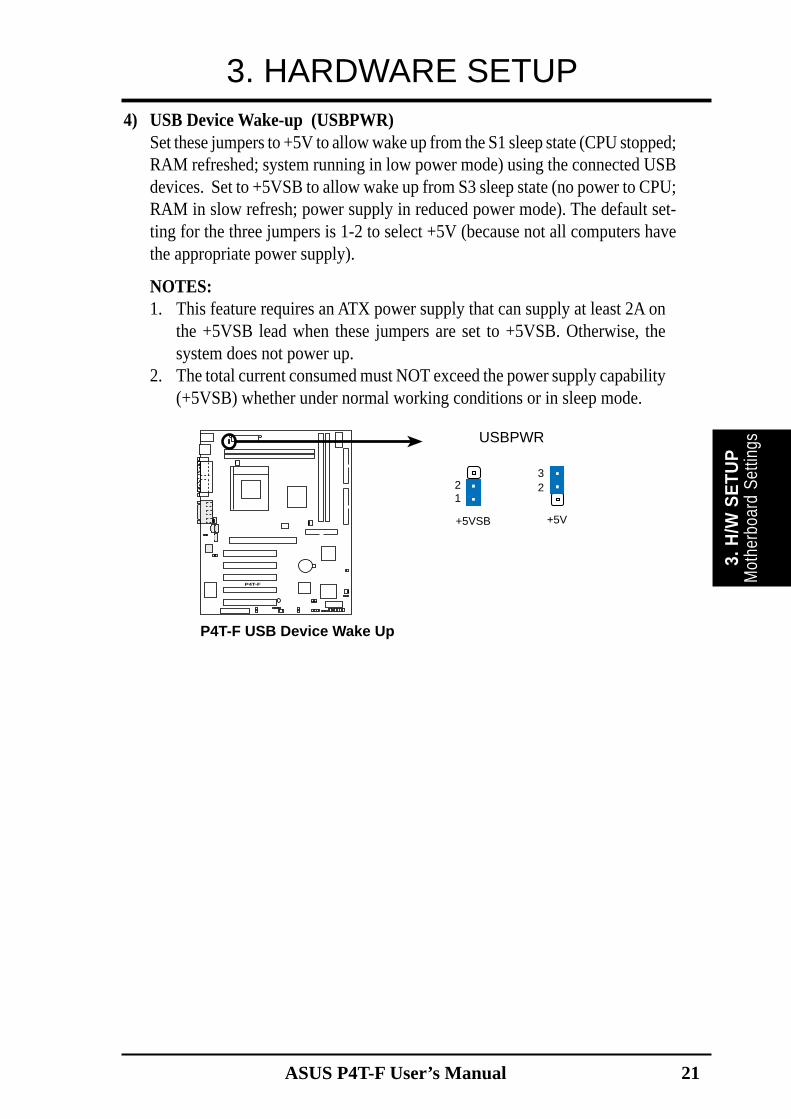
4) USB Device Wake-up (USBPWR)Set these jumpers to +5V to allow wake up from the S1 sleep state (CPU stopped;RAM refreshed; system running in low power mode) using the connected USBdevices. Set to +5VSB to allow wake up from S3 sleep state (no power to CPU;RAM in slow refresh; power supply in reduced power mode). The default set-ting for the three jumpers is 1-2 to select +5V (because not all computers havethe appropriate power supply).
NOTES:1. This feature requires an ATX power supply that can supply at least 2A on
the +5VSB lead when these jumpers are set to +5VSB. Otherwise, thesystem does not power up.
2. The total current consumed must NOT exceed the power supply capability(+5VSB) whether under normal working conditions or in sleep mode.

22 ASUS P4T-F User’s Manual
3. HARDWARE SETUP
Motherboard Settings3. H
/W S
ETU
P
P4T-F
P4T-F AUDIO Setting
ENABLE AUDIO DISABLE AUDIO
ADN
23
12
P4T-F
A7V266 CNR/USB Selection
USB2
1 2
CNRUSB
2 3
12
23
OC3J3-J3+
J3-J3+
OC3
6) USB2 / CNRUSB Selection (J3-J3-/OC3)The CNR slot can support an optional USB hub CNR card. Three jumpers areused to control selection of USB or CNR functions: J3-, J3+ and OC3. Thefactory default setting is for standard USB2 control. If a USB hub CNR card isused, reset these jumpers to CNRUSB setting shown below.
IMPORTANT! Always set all three jumpers accordingly when selecting a device.
5) Onboard Audio Setting (ADN) (audio models only)The onboard Audio Codec may be enabled or disabled using these jumpers.Disable the onboard Audio Codec if using a PCI audio card on any of theexpansion slots or a primary audio/modem CNR on a CNR slot (see CNR Slotlater in this section).Setting ADNEnable [1-2] (default)Disable [2-3]

23
3. HARDWARE SETUP
ASUS P4T-F User’s Manual
3.5 System MemoryNOTE: No hardware or BIOS setup is required after adding or removing memory.This motherboard has four 184-pin Rambus Inline Memory Modules (RIMM) sockets.These sockets support 64Mbit, 128Mbit, and 256Mbit Direct RDRAM technologies.
RIMMA1RIMMA2
RIMMB1RIMMB2
128MB RDRAM
128MB RDRAMC-RIMM
C-RIMM
a.
RIMMA1RIMMA2
RIMMB1RIMMB2
128MB RDRAM
128MB RDRAM
128MB RDRAM
128MB RDRAMc.
RIMMA1RIMMA2
RIMMB1RIMMB2
128MB RDRAM
128MB RDRAMC-RIMM
C-RIMM
b.
Location Memory Module Subtotal
RIMMA1 RDRAM x 1(Rows 0&1) C-RIMM (use when socket will not be populated)
RIMMA2 RDRAM x 1(Rows 2&3) C-RIMM (use when socket will not be populated)
RIMMB1 RDRAM x 1(Rows 4&5) C-RIMM (use when socket will not be populated)
RIMMB2 RDRAM x 1(Rows 6&7) C-RIMM (use when socket will not be populated)
TOTAL SYSTEM MEMORY =(2GB Max)
NOTE: When using only two memorymodules, it is recommended that youuse configuration a.
IMPORTANT1. The memory configuration of channel A (RIMMA1 and RIMMA2) and
channel B (RIMMB1 and RIMMB2) must be identical (see below).2. C-RIMMs (Continuity RIMM) must be used to complete the sockets that
are not populated by RDRAMs. A C-RIMM is necessary to avoid breakingthe signal lines, which are a serial connection in a Rambus interface, suchas used in this motherboard. This assures the electrical integrity of a Rambusinterface.
3. When C-RIMMs are required, it is recommended that they be inserted intoRIMMA2 and RIMMB2.
Syst
em M
emor
y3.
H/W
SE
TUP

24 ASUS P4T-F User’s Manual
3. HARDWARE SETUP
3.5.1 Installing MemoryThe memory module (RIMM) will fit in only one orientation.
IMPORTANT: Do not touch the memory module’s connectors. Handle the mod-ule only by the edges.
1. Make sure that the notch keys in the module are aligned with the small ribsinside the RIMM sockets.
2. With the ejectors in the open position (as shown), push down gently but firmlyon the memory module until it snaps into place. The guides on the socket’sejectors should go through the two mounting notches on the module and theejectors should close. If necessary, push the ejectors inward to secure the mod-ule in place.
Removing MemoryTo release a memory module, push both ejectors outward and pull the module straightup and out of the RIMM sockets.
WARNING! RIMM modules become extremely hot during operation. To re-duce the risk of personal injury from hot surfaces, allow the modules to cool offbefore removing them.
P4T-F
P4T-F 184-Pin RIMM Sockets
RIMM Sockets
RIMM with Heat Spreader
C-RIMMSystem M
emory
3. H/W
SE
TUP NOTCH KEYS
CONNECTORS
RDRAM (with heat spreader)MOUNTING NOTCH
RIBS (inside socket)EJECTOR(TOP VIEW)

25
3. HARDWARE SETUP
ASUS P4T-F User’s Manual
CPU
3. H
/W S
ETUP
3.6 Central Processing Unit (CPU)The motherboard provides a ZIF Socket for the P4 Socket 423 CPU. The CPU thatcame with the motherboard should have a fan attached to it to prevent overheating.If not, then purchase a fan before turning on the system.
P4T-F
P4T-F Socket 423
Gold Arrow
Socket 423 Pentium 4
3.6.1 CPU Installation1. Locate the P4 Socket 423 and
open it by pulling the lever gen-tly sideways away from thesocket. Then lift the lever up-wards. The socket lever must befully opened (90 to 100 degrees).
2. Insert the CPU with the correctorientation. The gold arrow ofthe CPU must be oriented to-ward the outer corner of thesocket base nearest to the tip ofthe lever handle.
3. Once completely inserted, press the CPU firmly and close the socketlever until it snaps into its locked position.
CAUTION! The CPU fits in one orientation and should drop easily intoplace. Do not force the CPU into the socket to avoid bending the pins. Ifthe CPU does not fit, check its alignment and look for bent pins.

26 ASUS P4T-F User’s Manual
3. HARDWARE SETUP
1. Mount the heatsink support braces:insert the four black plastic collars fromthe top through to the bottom of themotherboard. Insert the white plasticplugs into the middle of the blackplastic collars and pop them firmly outthe bottom of the motherboard.
CPU
Heatsink
3. H/W
SETUP
Step 1: Mount the Heatsink Support Braces:
3.6.2 CPU Heatsink Retention Module Installation
Parts Inventory:
1. Two black plastic heatsink supportbraces have built-in retaining clips.
2. Four black plastic collars andfour white plastic plugs.

27
3. HARDWARE SETUP
ASUS P4T-F User’s Manual
CPU
Hea
tsin
k3.
H/W
SET
UP
1. Open the retaining clips. Place theheatsink on the CPU. The heatsinkshould entirely cover the CPU. Theplastic heatsink support braces havebuilt-in retaining clips, right. Close andsnap the clips into the locked position.With the added weight of the CPU fanand heatsink locking brace, no extraforce is required to keep the CPU inplace.
2. Connect the CPU fan cable to the fan connector. (See 3.1 MotherboardLayout / 3.8 Connectors).
Step 2: Mount the Heatsink:
CAUTION! Take care not to scrape the motherboard surface whenmounting a clamp-style processor fan, or else damage may occur. Whenmounting a heatsink onto your CPU, make sure that exposed CPUcapacitors do not touch the heatsink, or else damage may occur! Referto heatsink/CPU documentation.
WARNING! Be sure that there is sufficient air circulation across theprocessor’s heatsink by regularly checking that your CPU fan is work-ing. Without sufficient circulation, the processor could overheat anddamage both the processor and the motherboard. You may install anauxiliary fan, if necessary.

28 ASUS P4T-F User’s Manual
3. HARDWARE SETUP
Expansion Cards
3. H/W
SETUP
3.7 Expansion Cards3.7.1 Expansion Card Installation Procedure1. Read the documentation for your expansion card and make any necessary hard-
ware or software settings for your expansion card, such as jumpers.
2. Remove your computer system’s cover and the bracket plate on the slot youintend to use. Keep the bracket for possible future use.
3. Carefully align the card’s connectors and press firmly.
4. Secure the card on the slot with the screw you removed above.
5. Replace the computer system’s cover.
6. Set up the BIOS if necessary
(such as IRQ XX Reserved for Legacy Device: Yes in 4.4.3 PCI Configuration)
7. Install the necessary software drivers for your expansion card.
WARNING! Unplug your power supply when adding or removing expansionCards or other system components. Failure to do so may cause severe damage toboth your motherboard and expansion cards. (See 3.3 Hardware Setup Proce-dure for more information).

ASUS P4T-F User’s Manual 29
3. HARDWARE SETUP
Exp
ansi
on C
ards
3. H
/W S
ETU
P
3.7.2 Assigning IRQs for Expansion CardsSome expansion cards need an IRQ to operate. Generally, an IRQ must be exclu-sively assigned to one use. In a standard design, there are 16 IRQs available butmost of them are already in use, leaving 6 IRQs free for expansion cards. If yourmotherboard has PCI audio onboard, an additional IRQ will be used. If your moth-erboard also has MIDI enabled, another IRQ will be used, leaving 4 IRQs free.
Standard Interrupt Assignments
IRQ Priority Standard Function0 1 System Timer1 2 Keyboard Controller2 N/A Programmable Interrupt3* 11 Communications Port (COM2)4* 12 Communications Port (COM1)5* 13 Sound Card (sometimes LPT2)6 14 Floppy Disk Controller7* 15 Printer Port (LPT1)8 3 System CMOS/Real Time Clock9* 4 ACPI Mode when enabled10* 5 IRQ Holder for PCI Steering11* 6 IRQ Holder for PCI Steering12* 7 PS/2 Compatible Mouse Port13 8 Numeric Data Processor14* 9 Primary IDE Channel15* 10 Secondary IDE Channel
*These IRQs are usually available for ISA or PCI devices.
Interrupt Request Table for this MotherboardINT-A INT-B INT-C INT-D INT-E INT-F INT-G INT-H
PCI slot 1 — — — — — shared — —PCI slot 2 — — — — — — used —PCI slot 3 — — — — — — — sharedPCI slot 4 — — — — used — — —PCI slot 5 — — shared — — — — —AGP slot used — — — — — — —USB HC0 — — — used — — — —USB HC1 — — — — — — — sharedSMB — shared — — — — — —AC’97 — shared — — — — — —
IMPORTANT: If using PCI cards on shared slots, make sure that the drivers sup-port “Share IRQ” or that the cards do not need IRQ assignments. Conflicts will arisebetween the two PCI groups that will make the system unstable or cards inoperable.

30 ASUS P4T-F User’s Manual
3. HARDWARE SETUP3.7.3 Accelerated Graphics Port (AGP Pro)This motherboard provides an accelerated graphics port (AGP Pro) to support a newgeneration of AGP graphics cards with ultra-high memory bandwidth.
IMPORTANT: Only 1.5V AGP cards are supported. ASUS® AGP 4X cards arerated for both 1.5 and 3.3 Volts. Early AGP cards only operate at 3.3 volts and willnot fit properly into the new AGP 4X slots. See examples of both types below:
P4T-F
P4T-F Accelerated Graphics Port (AGP PRO)
TOP VIEW
Rib (inside slot) Rib20-pin bay 28-pin bay
AGP Card without Retention Notch
An early 3.3V AGP card:Do not use.
A new 1.5 / 3.3V AGP card:OKAY to use.

ASUS P4T-F User’s Manual 31
3. HARDWARE SETUP
Exp
ansi
on C
ards
3. H
/W S
ETU
P
P4T-F
P4T-F Communication & Networking Riser Connectors
3.7.4 Communications and Networking Riser (CNR)This connector supports specially designed network, audio, or modem riser cards.Main processing is done through software adn controlled by the motherboard’ssystem chipset. This provides upgradeable network, audio, and/or modem solutionsat an incredibly low cost.

32 ASUS P4T-F User’s Manual
3. HARDWARE SETUP3.8 External Connectors
WARNING! Some pins are used for connectors or power sources. These areclearly distinguished from jumpers in the Motherboard Layout. Placing jumpercaps over these connector pins will cause damage to your motherboard.
IMPORTANT: Ribbon cables should always be connected with the red stripe toPin 1 on the connectors. Pin 1 is usually on the side closest to the power connec-tor on hard drives and CD-ROM drives, but may be on the opposite side onfloppy disk drives. Check the connectors before installation because there maybe exceptions. IDE ribbon cables must be less than 46 cm (18 in.), with thesecond drive connector no more than 15 cm (6 in.) from the first connector.
1) PS/2 Mouse Connector (Green 6-pin PS2KBMS)The system will direct IRQ12 to the PS/2 mouse if one is detected. If one is notdetected, expansion cards can use IRQ12. See PS/2 Mouse Function Controlin 4.4 Advanced Menu.
PS/2 Mouse (6-pin Female)
2) PS/2 Keyboard Connector (Purple 6-pin PS2KBMS)This connection is for a standard keyboard using an PS/2 plug (mini DIN). Thisconnector will not allow standard AT size (large DIN) keyboard plugs. Youmay use a DIN to mini DIN adapter on standard AT keyboards.
PS/2 Keyboard (6-pin Female)
Connectors
3. H/W
SE
TUP

ASUS P4T-F User’s Manual 33
3. HARDWARE SETUP
Con
nect
ors
3. H
/W S
ETU
P
3) Parallel Port Connector (Burgundy 25-pin PRINTER)You can enable the parallel port and choose the IRQ through Onboard ParallelPort (see 4.4.2 I/O Device Configuration).NOTE: Serial printers must be connected to the serial port.
5) Universal Serial Bus Ports (Black two 4 pin USB)Two USB ports are available for connecting USB devices. For additional USBports, you can use the USB headers (see USB Headers later in this section).NOTE: USB Function (see 4.4.3 PCI Configuration) must be Enabled to usethese ports.
COM2COM1Serial Ports (9-pin Male)
4) Serial Port Connectors (Teal/Turquoise 9-pin COM1, 9-pin COM2)Two serial ports are ready for a mouse or other serial devices. See OnboardSerial Port 1/2 in 4.4.2 I/O Device Configuration for settings.
Parallel Port (25-pin Female)
Universal Serial Bus (USB) 2
USB 1

34 ASUS P4T-F User’s Manual
Connectors
3. H/W
SE
TUP
3. HARDWARE SETUP6) Joystick/MIDI Connector (15 pin Female GAME_AUDIO)
You may connect game joysticks or game pades to this connector for playinggames. Connect MIDI devices for playing or editing audio.
Game/MIDI (15-pin Female)
7) Audio Port Connectors (Three 1/8” Female LINE IN, LINE OUT, MIC)Line Out can be connected to headphones or preferably powered speakers.Line In allows tape players or other audio sources to be recorded by your com-puter or played through the Line Out. Mic allows microphones to be connectedfor inputting voice.
MicLine InLine Out1/8" Stereo Audio Connectors
8) Floppy Disk Drive Connector (34-1pin FLOPPY)This connector supports the provided floppy drive ribbon cable. After connect-ing the single end to the board, connect the two plugs on the other end to thefloppy drives. (Pin 5 is removed to prevent inserting the cable into the wrongorientation).
P4T-F
NOTE: Orient the red markings onthe floppy ribbon cable to PIN 1.
P4T-F Floppy Disk Drive Connector
PIN 1
FLOPPY

ASUS P4T-F User’s Manual 35
3. HARDWARE SETUP
Con
nect
ors
3. H
/W S
ETU
P
9) Primary (Blue) / Secondary IDE Connectors (Two 40-1pin IDE)These connectors support the provided IDE hard disk ribbon cable. Connect thecable’s blue connector to the motherboard’s primary (recommended) or second-ary IDE connector. Then connect the gray connector to your UltraDMA/100slave device (hard disk drive) and the black connector to your UltraDMA/100master device. It is recommended that non-UltraDMA/100 devices be connectedto the secondary IDE connector. If you install two hard disks, you must config-ure the second drive to Slave mode. Please refer to your hard disk documenta-tion for the jumper settings. BIOS now supports specific device bootup (see 4.6Boot Menu). (Pin 20 is removed to prevent wrong orientations).
TIP: You may configure two hard disks to be both Masters with two ribboncables – one for the primary IDE connector and another for the secondary IDEconnector. You may install one operating system on an IDE drive and anotheron a SCSI drive and select the boot disk through 4.6 Boot Menu.
IMPORTANT: UltraDMA/100 IDE devices must use a 40-pin 80-conductor IDEcable for 100MByte/sec transfer rates.
P4T-F
P4T-F IDE Connectors
NOTE: Orient the red markings(usually zigzag) on the IDEribbon cable to PIN 1.
Sec
onda
ry ID
E C
onne
ctor
PIN 1
Prim
ary
IDE
Con
nect
or
PIN 1

36 ASUS P4T-F User’s Manual
Connectors
3. H/W
SE
TUP
3. HARDWARE SETUP10) Fan Connectors (3 pin MAIN_FAN, CPU_FAN, PCI_FAN)
These connectors support cooling fans of 350mA (4.2 Watts) or less. Orientatethe fans so that the heat sink fins allow airflow to go across the onboard heatsink(s) instead of the expansion slots. Depending on the fan manufacturer, thewiring and plug may be different. The red wire should be positive, while theblack should be ground. Connect the fan’s plug to the board taking into consid-eration the polarity of the connector.
NOTE: The “Rotation” signal is to be used only by a specially designed fan withrotation signal. The Rotations per Minute (RPM) can monitored using a utility suchas ASUS PC Probe or Intel LDCM.
WARNING! The CPU and/or motherboard will overheat if there is no airflowacross the CPU and onboard heatsinks. Damage may occur to the motherboardand/or the CPU fan if these pins are incorrectly used. These are not jumpers,do not place jumper caps over these pins.
P4T-F
P4T-F 12-Volt Cooling Fan Power
MAIN_FAN
CPU_FAN
PCI_FAN
GND
Rotation+12V
GND
Rotation+12V
GND
Rotation+12V

ASUS P4T-F User’s Manual 37
3. HARDWARE SETUP
Con
nect
ors
3. H
/W S
ETU
P
11) USB Headers (10-1 pin USB2)If the USB Ports on the back panels are inadequate, a USB header is availablefor two additional USB ports. Connect the 10-1 pin ribbon cable from the pro-vided 2-port USB connector set to the midboard 10-1 pin USB header and mountthe USB connector set to an open slot on your chassis.
P4T-F
P4T-F USB Headers
USB2
1 5
6 10
1: USB Power2: USBP2–3: USBP2+4: GND5: NC
6: USB Power7: USBP3–8: USBP3+9: GND
12) Internal Audio Connectors (4-pin MODEM, CD_IN, AUX)These connectors allow you to receive stereo audio input from such audio-vi-sual sources as a VIDEO or CD-ROM input, or MPEG card.
P4T-F
P4T-F Internal Audio Connectors
MODEMModem-Out
GroundModem-In
Ground
Right Audio Channel
Left Audio Channel
GroundGround
CD1 (Black)AUX (White)
VIDEO (Green)

38 ASUS P4T-F User’s Manual
Connectors
3. H/W
SE
TUP
3. HARDWARE SETUP
P4T-F
P4T-F True-Level Line Out Header
HEADPHONE
1
Headphone Left
GND
Headphone Right
P4T-F
P4T-F Internal Microphone Connector
MIC2
MIC Power
1
MIC Input
Ground
13) Internal Microphone Connector (3 pin MIC2) (optional)Microphone audio may be directly input through this connector.
14) Headphone (3 pin HEADPHONE) (optional)An external headphone feeds from the motherboard using this connector.

ASUS P4T-F User’s Manual 39
3. HARDWARE SETUP
Con
nect
ors
3. H
/W S
ETU
P
P4T-F
P4T-F Infrared Module Connector
Front View Back View
+5VIRTX
IRRX(NC)GND
+5V
IRR
X
IRT
X
(NC
)
GN
D
IR
1
15) Standard and Consumer Infrared (SIR) Module Connector (5-pin IR)This connector supports an optional wireless transmitting and receiving infraredmodule. This module mounts to a small opening on system cases that supportthis feature. You must also configure the setting through UART2 Use Infrared(see 4.4.2 I/O Device Configuration) to select whether UART2 is directed foruse with COM2 or IrDA. Use the five pins as shown in Back View and connecta ribbon cable from the module to the motherboard’s SIR connector accordingto the pin definitions.
P4T-F
P4T-F HDD Activity LED
TIP: If the case-mounted LED does notlight, try reversing the 2-pin plug.
HDDLED
16) IDE Activity LED (2-pin HDLED)This connector supplies power to the cabinet’s IDE activity LED. Read andwrite activity by devices connected to the Primary/Secondary IDE and Primary/Secondary ATA100 connectors will cause the LED to light up.

40 ASUS P4T-F User’s Manual
Connectors
3. H/W
SE
TUP
3. HARDWARE SETUP
P4T-F
P4T-F ATX &Auxiliary Power Connectors
ATX12V
ATXPWR
AUXPWR
Pin 1
CO
M
+3V
+5V
Key
+12V DCCOM
+12V DCCOM
Pin 1
Pin 1
+3.3VDC-12.0VDCCOMPS_ON#
COMCOM
COM-5.0VDC+5.0VDC+5.0VDC
PWR_OK
+12.0VDC
+3.3VDC+3.3VDC
COM
+5.0VDCCOM
+5.0VDC
COM
+5VSB
17) Power Supply Connectors (20-pin block ATXPWR) (4-pin ATX12V) (6pin block AUXPWR (optional)These connectors supply ATX 12V power. Each power supply plug inserts inone orientation only. Push down firmly and make sure the pins are aligned.
IMPORTANT: Make sure that your ATX 12V power supply (minimum recom-mended wattage: 230 watts; 300W for a fully-configured system) can supply atleast 20 amperes on the +5-volt lead and at least 720mA on the +5-volt standbylead (+5VSB). Your system may become unstable/unreliable and may experi-ence difficulty in powering up if your power supply is inadequate. For Wake-On-LAN support, your ATX power supply (minimum recommended wattage:230watts) must supply at least 720mA +5VSB.

ASUS P4T-F User’s Manual 41
3. HARDWARE SETUP
Con
nect
ors
3. H
/W S
ETU
P
P4T-F
P4T-F System Panel Connectors* Requires an ATX power supply.
PLE
D
Gro
und
MLE
D
PW
R
+5
V
Key
lock
+5V
Spe
aker
SpeakerConnector
Power LED
Gro
und
+5
V
Reset SW
SMI Lead
Message LED
Ext
SM
I#
Gro
und
Res
etG
roun
dG
roun
d
Gro
und
Keyboard Lock
ATX PowerSwitch*
The following diagram is for items 20–26:
20) System Power LED Lead (3-1 pin PWRLED)This 3-1 pin connector connects the system power LED, which lights when thesystem is powered on and blinks when it is in sleep mode.
21) Keyboard Lock Switch Lead (2-pin KEYLOCK)This 2-pin connector connects to the case-mounted key switch to allow key-board locking.
22) System Warning Speaker Connector (4-pin SPEAKER)This 4-pin connector connects to the case-mounted speaker. Two sources(LINE_OUT and SPEAKER) will allow you to hear system beeps and warn-ings. Only SPEAKER will allow you to hear system beeps before the integratedaudio has been properly initialized.
23) System Message LED Lead (2-pin MSG.LED)This indicates whether a message has been received from a fax/modem. TheLED will remain lit when there is no signal and blink when there is data re-ceived. This function requires an ACPI OS and driver support.
24) System Management Interrupt Lead (2-pin SMI)This allows the user to manually place the system into a suspend mode or “Green”mode, where system activity is decreased to save electricity and expand the lifeof certain components when the system is not in use. This 2-pin connector con-nects to the case-mounted suspend switch.
25) ATX Power Switch Lead (2-pin PWRSW)The system power is controlled by a momentary switch connected to this lead.Pressing the button once will switch the system between ON and SOFT OFF.Pushing the switch while in the ON mode for more than 4 seconds will turn thesystem off. The system power LED shows the status of the system’s power.
26) Reset Switch Lead (2-pin RESET)This 2-pin connector connects to the case-mounted reset switch for rebootingyour computer without having to turn off your power switch. This is a preferredmethod of rebooting to prolong the life of the system’s power supply.

42 ASUS P4T-F User’s Manual
Connectors
3. H/W
SE
TUP
3. HARDWARE SETUP(This page was intentionally left blank.)

ASUS P4T-F User’s Manual 43
3. HARDWARE SETUP
Pow
erin
g U
p3 .
H/W
SET
UP
3.9 Starting Up the First Time1. After all connections are made, close the system case cover.
2. Be sure that all switches are off (in some systems, marked with ), andthe power input voltage is set to comply with the standard used in yourcountry (220V-240V or 110-120V).
3. Connect the power supply cord into the power supply located on theback of your system case according to your system user’s manual.
4. Connect the power cord into a power outlet that is equipped with a surgeprotector.
5. You may then turn on your devices in the following order:a. Your monitorb. External SCSI devices (starting with the last device on the chain)c. Your system power. For ATX power supplies, you need to switch on
the power supply as well as press the ATX power switch on the frontof the case.
6. The power LED on the front panel of the system case will light. ForATX power supplies, the system LED will light when the ATX powerswitch is pressed. The LED on the monitor may light up or switch be-tween orange and green after the system’s if it complies with “green”standards or if it has a power standby feature. The system will then runpower-on tests. While the tests are running, the BIOS will alarm beepsor additional messages will appear on the screen. If you do not seeanything within 30 seconds from the time you turn on the power, thesystem may have failed a power-on test. Recheck your jumper settingsand connections or call your retailer for assistance.
Award BIOS Beep CodesBeep MeaningOne short beep when No error during POSTdisplaying logoLong beeps in an endless loop No DRAM installed or detectedOne long beep followed by Video card not found or video cardthree short beeps memory badHigh frequency beeps when CPU overheatedsystem is working System running at a lower frequency

ASUS P4T-F User’s Manual44
3. HARDWARE SETUP
Powering U
p3. H
/W SETU
P
7. During power-on, hold down <Delete> to enter BIOS setup. Follow theinstructions in 4. BIOS SETUP.
* Powering Off your computer: You must first exit or shut down youroperating system before switching off the power switch. For ATX powersupplies, you can press the ATX power switch after exiting or shuttingdown your operating system. If you use Windows 9X, click the Startbutton, click Shut Down, and then click Shut down the computer?The power supply should turn off after Windows shuts down.
NOTE: The message “You can now safely turn off your computer”will not appear when shutting down with ATX power supplies.

4. BIOS SETUP
4.1 Managing and Updating Your BIOS
4.1.1 Upon First Use of the Computer SystemIt is recommended that you save a copy of the original motherboard BIOSalong with a Flash Memory Writer utility (AFLASH.EXE) to a bootablefloppy disk in case you need to reinstall the BIOS later. AFLASH.EXE is aFlash Memory Writer utility that updates the BIOS by uploading a new BIOSfile to the programmable flash ROM on the motherboard. This file worksonly in DOS mode. To determine the BIOS version of your motherboard,check the last four numbers of the code displayed on the upper left-handcorner of your screen during bootup. Larger numbers represent a newer BIOSfile.
1. Type FORMAT A:/S at the DOS prompt to create a bootable systemfloppy disk. DO NOT copy AUTOEXEC.BAT & CONFIG.SYS to thedisk.
2. Type COPY D:\AFLASH\AFLASH.EXE A:\ (assuming D is your CD-ROM drive) to copy AFLASH.EXE to the just created boot disk.NOTE: AFLASH works only in DOS mode. It will not work with DOSprompt in Windows and will not work with certain memory drivers thatmay be loaded when you boot from your hard drive. It is recommendedthat you reboot using a floppy.
3. Reboot your computer from the floppy disk. NOTE: BIOS setup mustspecify “Floppy” as the first item in the boot sequence.
4. In DOS mode, type A:\AFLASH <Enter> to run AFLASH.
ASUS A7A266 User’s Manual 45
4 . B
IOS
SETU
P U
pdat
ing
BIO
S
IMPORTANT! If “unknown” is displayed after Flash Memory:, the memorychip is either not programmable or is not supported by the ACPI BIOS andtherefore, cannot be programmed by the Flash Memory Writer utility.

ASUS P4T-F User’s Manual46
4. BIOS SETUP
4. BIO
S SETUP
Updating BIO
S
5. Select 1. Save Current BIOS to File from the Main menu and press<Enter>. The Save Current BIOS To File screen appears.
4.1.2 Updating BIOS ProceduresWARNING! Only update your BIOS if you have problems with your mother-board and you know that the new BIOS revision will solve your problems.Careless updating can result in your motherboard having more problems!
1. Download an updated ASUS BIOS file from the Internet (WWW orFTP) (see ASUS CONTACT INFORMATION on page 3 for details)and save to the disk you created earlier.
2. Boot from the disk you created earlier.3. At the “A:\” prompt, type AFLASH and then press <Enter>.4. At the Main Menu, type 2 and then press <Enter>. The Update BIOS
Including Boot Block and ESCD screen appears.5. Type the filename of your new BIOS and the path, for example, A:\XXX-
XX.XXX, and then press <Enter>.NOTE: To cancel this operation, press <Enter>.
6. Type a filename and the path, for example, A:\XXX-XX.XXX and thenpress <Enter>.

ASUS P4T-F User’s Manual 47
4. BIOS SETUP
4 . B
IOS
SETU
P
6. When prompted to confirm the BIOS update, press Y to start the up-date.
Upd
atin
g BI
OS
NOTE: When you see the message “Boot Block is different”, youmay still press <Y> to update the BIOS. Yet if the update fails, yoursystem will run a greater risk of boot failure depending on whetherthe boot block is damaged or not.
7. The utility starts to program the new BIOS information into the flashROM. The boot block will be updated automatically only when neces-sary. This will minimize the chance that a failed update will preventyour system from booting up. When the programming is finished,Flashed Successfully will be displayed.

ASUS P4T-F User’s Manual48
4. BIOS SETUP
4. BIO
S SETUP
Updating BIO
S
8. Follow the onscreen instructions to continue.
WARNING! If you encounter problems while updating the new BIOS,DO NOT turn off your system since this might prevent your systemfrom booting up. Just repeat the process, and if the problem still per-sists, update the original BIOS file you saved to disk above. If the FlashMemory Writer utility was not able to successfully update a completeBIOS file, your system may not be able to boot up. If this happens, yoursystem will need servicing.

ASUS P4T-F User’s Manual 49
4. BIOS SETUP
4 . B
IOS
SETU
P
4.2 BIOS Setup ProgramThis motherboard supports a programmable EEPROM that can be updated usingthe provided utility as described in 4.1 Managing and Updating Your BIOS.
The utility is used if you are installing a motherboard, reconfiguring your system,or prompted to “Run Setup”. This section describes how to configure your systemusing this utility.
Even if you are not prompted to use the Setup program, at some time in the futureyou may want to change the configuration of your computer. For example, youmay want to enable the Security Password Feature or make changes to the powermanagement settings. It will then be necessary to reconfigure your system usingthe BIOS Setup program so that the computer can recognize these changes andrecord them in the CMOS RAM of the EEPROM.
The EEPROM on the motherboard stores the Setup utility. When you start up thecomputer, the system provides you with the opportunity to run this program. Thisappears during the Power-On Self Test (POST). Press <Delete> to call up the Setuputility. If you are a little bit late in pressing the mentioned key, POST will continuewith its test routines, thus preventing you from calling up Setup. If you still need tocall Setup, restart the system by pressing <Ctrl> + <Alt> + <Delete>, or by press-ing the Reset button on the system chassis. You can also restart by turning thesystem off and then back on again. But do so only if the first two methods fail.
The Setup program has been designed to make it as easy to use as possible. It is amenu-driven program, which means you can scroll through the various sub-menusand make your selections among the predetermined choices.
To access the BIOS Setup program, press the <Delete> key afterthe computer has run through its POST.
NOTE: Because the BIOS software is constantly being updated, the followingBIOS screens and descriptions are for reference purposes only and may not re-flect your BIOS screens exactly.
Pro
gram
Info
rmat
ion

ASUS P4T-F User’s Manual50
4. BIOS SETUP
4. BIO
S SETUP
4.2.1 BIOS Menu BarThe top of the screen has a menu bar with the following selections:
MAIN Use this menu to make changes to the basic system configuration.ADVANCED Use this menu to enable and make changes to the advanced
features.POWER Use this menu to configure and enable Power Management
features.BOOT Use this menu to configure the default system device used to lo-
cate and load the Operating System.EXIT Use this menu to exit the current menu or specify how to exit the
Setup program.
To access the menu bar items, press the right or left arrow key on the keyboarduntil the desired item is highlighted.
4.2.2 Legend BarAt the bottom of the Setup screen you will notice a legend bar. The keys in thelegend bar allow you to navigate through the various setup menus. The followingtable lists the keys found in the legend bar with their corresponding alternates andfunctions.
Navigation Key(s) Function Description<F1> or <Alt + H> Displays the General Help screen from anywhere in the BIOS
Setup
<Esc> Jumps to the Exit menu or returns to the main menu from a sub-menu
← or → (keypad arrow) Selects the menu item to the left or right
↑ or ↓ (keypad arrow) Moves the highlight up or down between fields
- (minus key) Scrolls backward through the values for the highlighted field
+ (plus key) or spacebar Scrolls forward through the values for the highlighted field
<Enter> Brings up a selection menu for the highlighted field
<Home> or <PgUp> Moves the cursor to the first field
<End> or <PgDn> Moves the cursor to the last field
<F5> Resets the current screen to its Setup Defaults
<F10> Saves changes and exits Setup
Menu Introduction

ASUS P4T-F User’s Manual 51
4. BIOS SETUP
4 . B
IOS
SETU
P
General HelpIn addition to the Item Specific Help window, the BIOS setup program also pro-vides a General Help screen. This screen can be called up from any menu by sim-ply pressing <F1> or the <Alt> + <H> combination. The General Help screen liststhe legend keys with their corresponding alternates and functions.
Saving Changes and Exiting the Setup ProgramSee 4.7 Exit Menu for detailed information on saving changes and exiting thesetup program.
Scroll BarWhen a scroll bar appears to the right of a help window, it indicates that there ismore information to be displayed that will not fit in the window. Use <PgUp> and<PgDn> or the up and down arrow keys to scroll through the entire help docu-ment. Press <Home> to display the first page, press <End> to go to the last page.To exit the help window, press <Enter> or <Esc>.
Sub-MenuNote that a right pointer symbol (as shown in the left view) appears to the left of
certain fields. This pointer indicates that a sub-menu can belaunched from this field. A sub-menu contains additional op-tions for a field parameter. To call up a sub-menu, simply movethe highlight to the field and press <Enter>. The sub-menuwill then immediately appear. Use the legend keys to entervalues and move from field to field within a sub-menu just asyou would within a menu. Use the <Esc> key to return to themain menu.
Take some time to familiarize yourself with each of the leg-end keys and their corresponding functions. Practice navigating through the vari-ous menus and sub-menus. If you accidentally make unwanted changes to any ofthe fields, use the set default hot key <F5>. While moving around through theSetup program, note that explanations appear in the Item Specific Help windowlocated to the right of each menu. This window displays the help text for the cur-rently highlighted field.
NOTE: The item heading in square brackets represents the default setting forthat field.
Men
u In
trodu
ctio
n
ASUS P4T-F User’s Manual52
4. BIOS SETUP
4. BIO
S SETUP
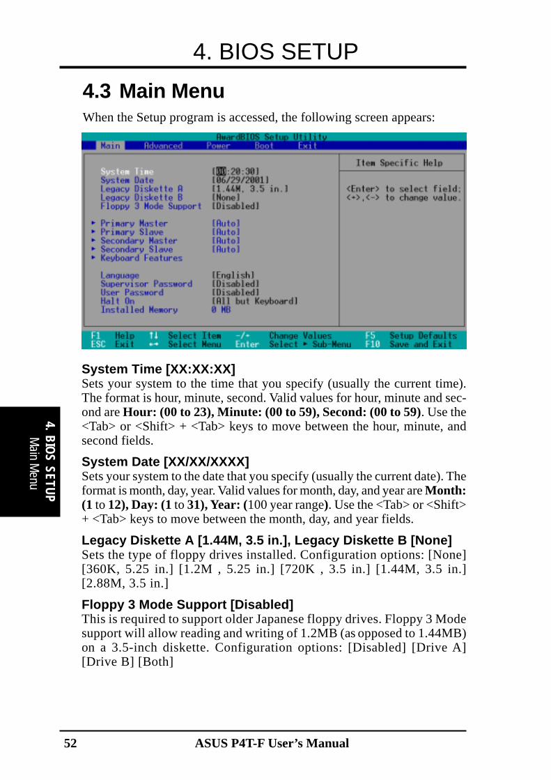
System Time [XX:XX:XX]Sets your system to the time that you specify (usually the current time).The format is hour, minute, second. Valid values for hour, minute and sec-ond are Hour: (00 to 23), Minute: (00 to 59), Second: (00 to 59). Use the<Tab> or <Shift> + <Tab> keys to move between the hour, minute, andsecond fields.
System Date [XX/XX/XXXX]Sets your system to the date that you specify (usually the current date). Theformat is month, day, year. Valid values for month, day, and year are Month:(1 to 12), Day: (1 to 31), Year: (100 year range). Use the <Tab> or <Shift>+ <Tab> keys to move between the month, day, and year fields.
Legacy Diskette A [1.44M, 3.5 in.], Legacy Diskette B [None]Sets the type of floppy drives installed. Configuration options: [None][360K, 5.25 in.] [1.2M , 5.25 in.] [720K , 3.5 in.] [1.44M, 3.5 in.][2.88M, 3.5 in.]
Floppy 3 Mode Support [Disabled]This is required to support older Japanese floppy drives. Floppy 3 Modesupport will allow reading and writing of 1.2MB (as opposed to 1.44MB)on a 3.5-inch diskette. Configuration options: [Disabled] [Drive A][Drive B] [Both]
4.3 Main MenuWhen the Setup program is accessed, the following screen appears:
Main M
enu

ASUS P4T-F User’s Manual 53
4. BIOS SETUP
4 . B
IOS
SETU
P
NOTE: Before attempting to configure a hard disk drive, make sure youhave the configuration information supplied by the manufacturer of thedrive. Incorrect settings may cause your system to not recognize the in-stalled hard disk. To allow the BIOS to detect the drive type automati-cally, select [Auto].
Type [Auto]Select [Auto] to automatically detect an IDE hard disk drive. If automaticdetection is successful, the correct values will be filled in for the remainingfields on this sub-menu. If automatic detection fails, your hard disk drivemay be too old or too new. You can try updating your BIOS or enter theIDE hard disk drive parameters manually.
NOTE: After the IDE hard disk drive information has been entered intoBIOS, new IDE hard disk drives must be partitioned (such as with FDISK)and then formatted before data can be read from and write on. PrimaryIDE hard disk drives must have its partition set to active (also possiblewith FDISK).
Other options for the Type field are:
[None] - to disable IDE devices
4.3.1 Primary & Secondary Master/Slave
Mas
ter/S
lave
Driv
es

ASUS P4T-F User’s Manual54
4. BIOS SETUP
4. BIO
S SETUP
IMPORTANT: If your hard disk was already formatted on an older previous system,incorrect parameters may be detected. You will need to enter the correct parametersmanually or use low-level format if you do not need the data stored on the hard disk.If the parameters listed differ from the ones used when the disk was formatted, thedisk will not be readable. If the auto-detected parameters do not match the ones thatshould be used for your disk, you should enter the correct ones manually by setting[User Type HDD].
Master/Slave D
rives
[User Type HDD]
Manually enter the number of cylinders, heads and sectors per track foryour drive. Refer to your drive documentation or look on the drive for thisinformation. If no drive is installed or if you are removing a drive and notreplacing it, select [None].
Translation Method [LBA]Select the hard disk drive type in this field. When Logical Block Address-ing is enabled, 28-bit addressing of the hard drive is used without regardfor cylinders, heads, or sectors. Note that LBA Mode is necessary for driveswith greater than 504MB in storage capacity. Configuration options: [LBA][LARGE] [Normal] [Match Partition Table] [Manual]
CylindersThis field configures the number of cylinders. Refer to your drive docu-mentation to determine the correct value to enter into this field. NOTE: Tomake changes to this field, the Type field must be set to [User Type HDD]and the Translation Method field must be set to [Manual].

ASUS P4T-F User’s Manual 55
4. BIOS SETUP
4 . B
IOS
SETU
P M
aste
r/Sla
ve D
rives
HeadThis field configures the number of read/write heads. Refer to your drivedocumentation to determine the correct value to enter into this field. NOTE:To make changes to this field, the Type field must be set to [User TypeHDD] and the Translation Method field must be set to [Manual].
SectorThis field configures the number of sectors per track. Refer to your drivedocumentation to determine the correct value to enter into this field. NOTE:To make changes to this field, the Type field must be set to [User TypeHDD] and the Translation Method field must be set to [Manual].
CHS CapacityThis field shows the drive’s maximum CHS capacity calculated automati-cally by the BIOS from the drive information you entered.
Maximum LBA CapacityThis field shows the drive’s maximum LBA capacity calculated automati-cally by the BIOS from the drive information you entered.
Multi-Sector Transfers [Maximum]This option automatically sets the number of sectors per block to the high-est number supported by the drive. This field can also be configured manu-ally. Note that when this field is automatically configured, the set valuemay not always be the fastest value for the drive. Refer to the documenta-tion that came with your hard drive to determine the optimal value and setit manually. NOTE: To make changes to this field, the Type field must beset to [User Type HDD]. Configuration options: [Disabled] [2 Sectors] [4Sectors] [8 Sectors] [16 Sectors] [32 Sectors] [Maximum]
SMART Monitoring [Disabled]This allows the enabling or disabling of the S.M.A.R.T. (Self-Monitoring,Analysis and Reporting Technology) system which utilizes internal harddisk drive monitoring technology. This feature is normally disabled be-cause system resources used in this feature may decrease system perfor-mance. Configuration options: [Disabled] [Enabled]
PIO Mode [4]This option lets you set a PIO (Programmed Input/Output) mode for theIDE device. Modes 0 through 4 provide successively increased performance.Configuration options: [0] [1] [2] [3] [4]
Ultra DMA Mode [Disabled]Ultra DMA capability allows improved transfer speeds and data integrityfor compatible IDE devices. Set to [Disabled] to suppress Ultra DMA ca-pability. NOTE: To make changes to this field, the Type field must be setto [User Type HDD]. Configuration options: [0] [1] [2] [3] [4] [Disabled]

ASUS P4T-F User’s Manual56
4. BIOS SETUP
4. BIO
S SETUP
Other options for “Type:” are:[CD-ROM] - for IDE CD-ROM drives[LS-120] - for LS-120 compatible floppy disk drives[ZIP] - for ZIP compatible disk drives[MO] - for IDE magneto optical disk drives[Other ATAPI Device] - for IDE devices not listed here
After using the legend keys to make your selections on this sub-menu,press the <Esc> key to exit back to the Main menu. When the Main menuappears, you will notice that the drive size appear in the field for the harddisk drive that you just configured.
Main M
enuBoot Up NumLock Status [On]This field enables users to activate the Number Lock function upon systemboot. Configuration options: [Off] [On]
Keyboard Auto-Repeat Rate [12/Sec]This controls the speed at which the system registers repeated keystrokes.Options range from 6 to 30 characters per second. Configuration options:[6/Sec] [8/Sec] [10/Sec] [12/Sec] [15/Sec] [20/Sec] [24/Sec] [30/Sec]
Keyboard Auto-Repeat Delay [1/4 Sec]This field sets the time interval for displaying the first and second charac-ters. Configuration options: [1/4 Sec] [1/2 Sec] [3/4 Sec] [1 Sec]
4.3.2 Keyboard Features

ASUS P4T-F User’s Manual 57
4. BIOS SETUP
4 . B
IOS
SETU
P M
ain
Men
u
Halt On [All Errors]This field determines which types of errors will cause the system to halt. Configura-tion options: [All Errors] [No Error] [All but Keyboard] [All but Disk] [All butDisk/Keyboard]
Installed Memory [XXX MB]This display-only field displays the amount of conventional memory detected by thesystem during bootup. You do not need to make changes to this field.
Language [English]This allows selection of the BIOS’ displayed language. Currently only English is available.
Supervisor Password [Disabled] / User Password [Disabled]These fields allow you to set the passwords. To set the password, highlight the appro-priate field and press <Enter>. Type in a password and press <Enter>. You can type upto eight alphanumeric characters. Symbols and other keys are ignored. To confirm thepassword, type the password again and press the <Enter>. The password is now set to[Enabled]. This password allows full access to the BIOS Setup menus. To clear thepassword, highlight this field and press <Enter>. The same dialog box as above willappear. Press <Enter> and the password will be set to [Disabled].A Note about PasswordsThe BIOS Setup program allows you to specify passwords in the Main menu. Thepasswords control access to the BIOS during system startup. The passwords are notcase sensitive. In other words, it makes no difference whether you enter a passwordusing upper or lowercase letters. The BIOS Setup program allows you to specify twoseparate passwords: a Supervisor password and a User password. When disabled, any-one may access all BIOS Setup program functions. When enabled, the Supervisorpassword is required for entering the BIOS Setup program and having full access to allconfiguration fields.Forgot the Password?If you forgot the password, you can clear the password by erasing the CMOS Real TimeClock (RTC) RAM. The RAM data containing the password information is powered by theonboard button cell battery. To erase the RTC RAM: (1)Unplug your computer; (2)Uncapthe blue jumper cap from default [1-2]; (3)Place the jumper cap onto pins [2-3] toshort the RTC CMOS registry and erase its memory; (4)Uncap the jumpers andreturn the cap to the operational default position [1-2]; (5)Turn ON your computer; (6)Hold down <Delete> during bootup and enter BIOS setup to re-enter user preferences.
P4T-F
P4T-F Clear RTC RAM
Short solder pointsto Clear CMOS
CLRTCIntel I/OController
Hub(ICH2)

ASUS P4T-F User’s Manual58
4. BIOS SETUP
4. BIO
S SETUP
4.4 Advanced Menu
Advanced Menu
CPU Internal Frequency [Manual]When the motherboard is set to JumperFree™ mode, this field allows youto select the internal frequency of your CPU. Select [Manual] if you wantto make changes to the subsequent 2 fields. Note that selecting a frequencyhigher than the CPU manufacturer recommends may cause the system tohang or crash.
CPU Frequency Multiple [14.0x]This field automatically sets the frequency multiple between the CPU’sinternal frequency (CPU speed) and the external frequency. Set this fieldin conjunction with the CPU Front Side Bus Frequency (MHz) to matchthe speed of the CPU. Configuration options: [10x] [11x]...[19x] [20x]
CPU/Front Side Bus Frequency (MHz) (if CPU Speed set to [Manual])This feature tells the clock generator which frequency to send to thesystem bus and PCI bus. The bus frequency (external frequency)multiplied by the bus multiple equals the CPU speed. Configuration rangesfrom 100/33 to 227/57.
CPU Vcore [1.700V]This field determines the range of core voltage available to the CentralProcessing Unit. Configuration options: [1.850] [1.825] [1.800] [1.775][1.750] [1.725] [1.700]
RDRAM Turbo Mode [Disabled]This feature enables the RDRAM Turbo feature. Select to improve systemperformance. BIOS will optimize the RDRAM timing register.Configuration options: [Disabled] [Enabled]

ASUS P4T-F User’s Manual 59
4. BIOS SETUP
4 . B
IOS
SETU
PAd
vanc
ed M
enu
RDRAM Frequency:FSB Ratio (MHz) [Auto]This feature tells the clock generator which frequency to send to theRDRAM. The default setting [Auto] makes the system detect and set theratio according to the type of RDRAM module. The [Auto] default bal-ances performance with stability. Alternatively, with PC600 RDRAM, se-lect [3x], and with PC800 RDRAM, select [4x]. If overclocking the CPU,select [3x] to maintain stability. Configuration options: [Auto] [3x] [4x]APIC [Disabled]This field is an Advanced Programmable Interrupt Controller. It isfunctional only with Windows XP or 2000. Enabling the A.P. I. C. featurereduces interrupt sharing and improves system performance.Configuration options: [Disabled] [Enabled]CPU Level 1 Cache, CPU Level 2 Cache [Enabled]These fields allow you to choose from the default of [Enabled] or choose[Disabled] to turn on or off the CPU’s Level 1 and Level 2 built-in cache.Configuration options: [Disabled] [Enabled]CPU Fast String [Enabled]When set to [Enabled], the CPU has direct access to the memory. Leave ondefault setting for best performance. Configuration options: [Disabled][Enabled]FPU OPCODE Compatible Mode [Disabled]Leave on default setting for optimized performance of Pentium 4 proces-sor. Configuration options: [Disabled] [Enabled]BIOS Update [Enabled]This functions as an update loader integrated into the BIOS to supply theprocessor with the required data. In the default position of [Enabled], theBIOS will load the update on all processors during system bootup. Con-figuration options: [Disabled] [Enabled]PS/2 Mouse Function Control [Auto]The default of [Auto] allows the system to detect a PS/2 mouse on startup.If detected, IRQ12 will be used for the PS/2 mouse. IRQ12 will be re-served for expansion cards only if a PS/2 mouse is not detected. [Enabled]will always reserve IRQ12, whether on startup a PS/2 mouse is detected ornot. Configuration options: [Enabled] [Auto]USB Legacy Support [Auto]This motherboard supports Universal Serial Bus (USB) devices. The de-fault of [Auto] allows the system to detect a USB device on startup. Ifdetected, USB controller legacy mode will be enabled. If not detected, USBcontroller legacy mode will be disabled. When this field is set to [Dis-abled], USB controller legacy mode is disabled no matter whether you areusing a USB device or not. Configuration options: [Disabled] [Enabled][Auto]

ASUS P4T-F User’s Manual60
4. BIOS SETUP
4. BIO
S SETUP
JumperFree N
otes
OS/2 Onboard Memory > 64M [Disabled]When using OS/2 operating systems with installed DRAM of greater than64MB, you need to set this option to [Enabled]; otherwise, leave this on[Disabled]. Configuration options: [Disabled] [Enabled]
Notes for JumperFree ModeCPU Upgrade/ReinstallationTo ensure that your system can enter BIOS setup after the processor hasbeen changed or reinstalled, your system will start up running at a busspeed of 100MHz and a fail-safe CPU internal frequency (8x100MHz). Itwill then automatically take you to the Advanced menu with a popup menuof all the officially possible CPU internal frequencies.
System HangupIf your system crashes or hangs due to improper frequency settings, powerOFF your system and restart. The system will start up in safe mode runningand enter BIOS setup.

ASUS P4T-F User’s Manual 61
4. BIOS SETUP
4 . B
IOS
SETU
PC
hip
Con
figur
atio
n
4.4.1 Chip Configuration
Data Integrity Mode [Non-ECC]This setting establishes the type of RDRAM memory installed on the com-puter. Configuration options: [Non-ECC] [ECC]
RDRAM Pool B State [Standby]This sets the operating state of the RDRAM devices in Pool B. Selecting[Nap] allows the RDRAM in Pool B to enter power-saving mode. [Standby]allows the RDRAM in Pool B to return to the working state quickly. Con-figuration options: [Standby] [Nap]
AGP Fast-Write [Enabled]This controls the AGP fast-write function. Configuration options: [Enabled][Disabled]
Graphics Window Size [64MB]This feature allows you to select the size of mapped memory for AGPgraphic data. Configuration options: [4MB] [8MB] [16MB] [32MB][64MB] [128MB] [256MB]
Video Memory Cache Mode [UC]USWC (uncacheable, speculative write combining) is a new cache tech-nology for the video memory of the processor. It can greatly improve thedisplay speed by caching the display data. You must set this to UC(uncacheable) if your display card cannot support this feature; otherwiseyour system may not boot. Configuration options: [UC] [USWC]
ASUS P4T-F User’s Manual62
4. BIOS SETUP
4. BIO
S SETUP
Chip C
onfiguration
Memory Hole At 15M-16M [Disabled]This field allows you to reserve an address space for ISA expansion cardsthat require it. Setting the address space to a particular setting will makethat memory space unavailable to the system. Expansion cards can onlyaccess memory up to 16MB. Configuration options: [Disabled] [Enabled]
PCI 2.1 Support [Enabled]This function allows you to enable or disable PCI 2.1 features includingpassive release and delayed transaction. Configuration options: [Disabled][Enabled]
Onboard PCI IDE Enable [Both]You can select to enable the primary IDE channel, secondary IDE channel,both, or disable both channels. Configuration options: [Both] [Primary][Secondary] [Disabled]

ASUS P4T-F User’s Manual 63
4. BIOS SETUP
4 . B
IOS
SETU
P
4.4.2 I/O Device Configuration
I/O
Dev
ice
Con
fig
Onboard AC97 Controller [Auto]The motherboard offers an AC97 Audio Controller chip. BIOS will auto-matically activate the Audio Controller if it is available. Configuration op-tions; [Auto] [Disabled]
Onboard FDC Swap A&B [No Swap]This option selects drive letter assignments. Configuration options; [NoSwap] [Swap AB]
Floppy Disk Access Control [R/W]When set to [Read Only], this field protects files from being copied tofloppy disks by allowing reads from the floppy disk drive but not writes.The setup default [R/W] allows both reads and writes. Configuration op-tions: [R/W] [Read Only]
Onboard Serial Port 1 [3F8H/IRQ4], Onboard Serial Port 2 [2F8H/IRQ3]These fields allow you to set the addresses for the onboard serial connec-tors. Serial Port 1 and Serial Port 2 must have different addresses. Con-figuration options: [3F8H/IRQ4] [2F8H/IRQ3] [3E8H/IRQ4] [2E8H/IRQ10] [Disabled]
UART2 Use Standard Infrared [Disabled]When enabled, this field activates the onboard standard infrared featureand sets the second serial UART to support the infrared module connectoron the motherboard. If your system already has a second serial port con-nected to the onboard COM2 connector, it will no longer work if you en-able the infrared feature. See Infrared Module Connector in3.8 External Connectors. Configuration options: [Disabled] [Enabled]

ASUS P4T-F User’s Manual64
4. BIOS SETUP
4. BIO
S SETUP
I/O D
evice Config
Onboard Parallel Port [378H/IRQ7]This field sets the address of the onboard parallel port connector. If youdisable this feature, Parallel Port Mode and ECP DMA Select configura-tions will not be available. Configuration options: [Disabled] [378H/IRQ7][278H/IRQ5]
Parallel Port Mode [ECP+EPP]This field allows you to set the operation mode of the parallel port. [Nor-mal] allows normal-speed operation but in one direction only; [EPP] al-lows bidirectional parallel port operation; [ECP] allows the parallel port tooperate in bidirectional DMA mode; [ECP+EPP] allows normal speed op-eration in a two-way mode. Configuration options: [Normal] [EPP] [ECP][ECP+EPP]
ECP DMA Select [3]This field allows you to configure the parallel port DMA channel for theselected ECP mode. This selection is available only if you select [ECP] or[ECP+EPP] in Parallel Port Mode above. Configuration options: [1] [3]
Onboard Game Port [200H-207H]This field sets the I/O address to the game port. Configuration options;[200H-207H] [208H-20FH]
Onboard MIDI I/O [330H-331H]This field sets the I/O address and IRQ for MIDI. Configuration options;[330H-331H] [300H-301H]
Onboard MIDI IRQ [10]This field indicates the onboard IRQ assignment for MIDI. Configurationoptions; [3 ,4, 5, 7, 9, 10, 11, 12, 14, 15]

ASUS P4T-F User’s Manual 65
4. BIOS SETUP
4 . B
IOS
SETU
P
4.4.3 PCI Configuration
PCI C
onfig
urat
ion
Slot 1 IRQ, Slot 2 IRQ, Slot 3, Slot 4, Slot 5 IRQ [Auto]These fields set how IRQ use is determined for each PCI slot. The defaultsetting for each field is [Auto], which uses auto-routing to dassign IRQs.Configuration options: [Auto] [NA] [3] [4] [5] [7] [9] [10] [11] [12] [14][15]
PCI/VGA Palette Snoop [Disabled]Some nonstandard VGA cards, such as graphics accelerators or MPEG videocards, may not show colors properly. The setting [Enabled] should correctthis problem. Otherwise, leave this on the default setting of [Disabled].Configuration options: [Disabled] [Enabled]
PCI Latency Timer [32]Leave on default setting for best performance vs. stability.
USB Function [Enabled]This motherboard supports Universal Serial Bus (USB) devices. Set to [Enabled] ifyou want to use USB devices. Configuration options: [Disabled] [Enabled]
Primary VGA BIOS [PCI Card]If your computer has both PCI and AGP VGA cards, this field allows youto select which of the cards will act as your primary graphics card. [AGPCard] uses the AGP card as your primary card. The default, [PCI Card],allows your PCI graphics card to take precedence when detected. Configu-ration options: [PCI Card] [AGP Card]

ASUS P4T-F User’s Manual66
4. BIOS SETUP
4. BIO
S SETUP
PCI C
onfiguration
PCI/PNP IRQ Resource Exclusion
IRQ XX Reserved for Legacy Device [No/ICU]These fields indicate whether or not the displayed IRQ for each field isbeing used by an onboard legacy (non-PnP) device. The default value indi-cates either that the displayed IRQ is not used or that the ISA Configura-tion Utility (ICU) is being used to determine if a legacy device is using thatIRQ. If the IRQ is required by a legacy device, then reserce the IRQ byselecting [Yes]. Otherwise, select [No/ICU] to release the IRQ to OS.Configuration options: [No/ICU] [Yes]

ASUS P4T-F User’s Manual 67
4. BIOS SETUP
4 . B
IOS
SETU
PPo
wer
Men
u
4.4.4 Shadow Configuration
Video ROM BIOS Shadow [Enabled]This field allows you to change the video BIOS location from ROM toRAM. Relocating to RAM enhances system performance, as informationaccess is faster than the ROM. Configuration options: [Disabled] [Enabled]
C8000-DFFFF Shadow [Disabled]These fields are used for shadowing other expansion card ROMs. If youinstall other expansion cards with ROMs on them, you will need to knowwhich addresses the ROMs use to shadow them specifically. Shadowing aROM reduces the memory available between 640K and 1024K by theamount used for this purpose. Configuration options: [Disabled] [Enabled]

ASUS P4T-F User’s Manual68
4. BIOS SETUP
4. BIO
S SETUP
Power M
enu
4.5 Power MenuThe Power menu allows you to reduce power consumption. This feature turns off thevideo display and shuts down the hard disk after a period of inactivity.
Power Management [User Define]This option must be enabled to use any of the automatic power savingfeatures. If this menu item is set to [Disabled], power management featureswill not function regardless of other field settings on this menu. The [UserDefine] option allows you to make your own selections in the Power menu.When set to [Max Saving], system power will be conserved to its greatestamount. The Suspend Mode field will then be set to predefined value thatensures maximum power savings.
This field acts as the master control for the power management modes.[Max Saving] puts the system into power saving mode after a brief periodof system inactivity; [Min Saving] is almost the same as [Max Saving]except that the system inactivity period is longer; [Disabled] disables thepower saving features; [User Define] allows you to set power saving op-tions according to your preference. Configuration options: [User Define][Disabled] [Min Saving] [Max Saving]
IMPORTANT: Advanced Power Management (APM) should be installed to keepthe system time updated when the computer enters suspend mode activated bythe BIOS Power Management. For DOS environments, you need to add the state-ment, DEVICE=C:\DOS\POWER.EXE, to your CONFIG.SYS file. For Win-dows 3.x and Windows 95, you need to install Windows with the APM feature.For Windows 98 and later, APM is automatically installed. A battery and powercord icon labeled “Power Management” will appear in the “Control Panel.”Choose “Advanced” in the Power Management Properties dialog box.

ASUS P4T-F User’s Manual 69
4. BIOS SETUP
4 . B
IOS
SETU
P P
ower
Up
Con
trol
Video Off Option [Suspend -> Off ]This field determines when to activate the video off feature for monitorpower management. Configuration options: [Always On] [Suspend -> Off]
Video Off Method [DPMS OFF]This field defines the video off features. The DPMS (Display Power Manage-ment System) feature allows the BIOS to control the video display card if itsupports the DPMS feature. [Blank Screen] only blanks the screen (use thisfor monitors without power management or “green” features. If set up in yoursystem, your screen saver will not display with [Blank Screen] selected). [V/H SYNC+Blank] blanks the screen and turns off vertical and horizontal scan-ning. Configuration options: [Blank Screen] [V/H SYNC+Blank] [DPMSStandby] [DPMS Suspend] [DPMS OFF] [DPMS Reduce ON]
HDD Power Down [Disabled]Shuts down any IDE hard disk drives in the system after a period of inac-tivity as set in this user-configurable field. This feature does not affectSCSI hard drives. Configuration options: [Disabled] [1 Min] [2 Min] [3Min]...[15 Min]
Suspend-to-RAM Capability [Disabled]This field lets you to enable or disable the Suspend-to-RAM (STR) featureallowing the system to go into suspend mode after the specified time in theSuspend Mode parameter. Configuration options: [Disabled] [enabled]
Suspend Mode [Disabled]Sets the time period before the system goes into suspend mode. Configu-ration options: [Disabled] [30 Sec] [1 Min] [2 Min]...[1 Hour]
PWR Button < 4 Secs [Soft Off]When set to [Soft off], the ATX switch can be used as a normal systempower-off button when pressed for less than 4 seconds. [Suspend] allowsthe button to have a dual function where pressing less than 4 seconds willplace the system in sleep mode. Regardless of the setting, holding the ATXswitch for more than 4 seconds will power off the system. Configurationoptions: [Soft off] [Suspend]

ASUS P4T-F User’s Manual70
4. BIOS SETUP
4. BIO
S SETUP
Power U
p Control
4.5.1 Power Up Control
AC PWR Loss Restart [Disabled]This allows you to set whether you want your system to reboot after thepower has been interrupted. [Disabled] leaves your system off and [En-abled] reboots your system. [Previous State] sets your system back to thestate it is before the power interruption. Configuration options: [Disabled][Enabled] [Previous State]
PWR Up On external Modem Act [Disabled]This allows either settings of [Enabled] or [Disabled] for powering up thecomputer when the external modem receives a call while the computer isin Soft-off mode. NOTE: The computer cannot receive or transmit datauntil the computer and applications are fully running. Thus connection can-not be made on the first try. Turning an external modem off and then backon while the computer is off causes an initialization string that will alsocause the system to power on. Configuration options: [Disabled] [Enabled]
Wake On LAN or PCI Modem card [Disabled]Wake-On-LAN or a PCI modem card prermits PC bootup from anothercomputer via a network by sending a wake-up frame or signal. Configura-tion options: [Disabled] [Enabled]
Wake On PS2 KB / PS2 Mouse [Disabled]Wake On PS2 KB / PS2 Mouse permits PC bootup from the keyboard ormouse. Configuration options: [Disabled] [Enabled]
IMPORTANT: This feature requires an optional network interface with Wake-On-LAN and an ATX power supply with at least 720mA +5V standby power.
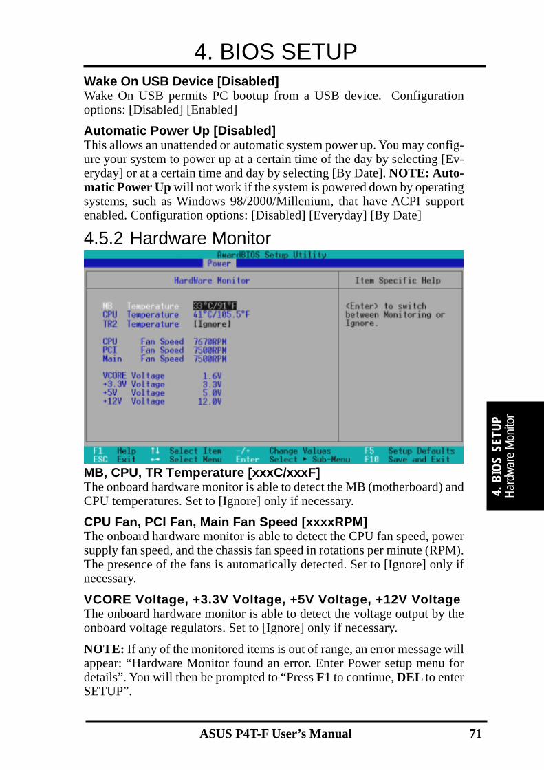
ASUS P4T-F User’s Manual 71
4. BIOS SETUP
4 . B
IOS
SETU
PH
ardw
are
Mon
itor
4.5.2 Hardware Monitor
Wake On USB Device [Disabled]Wake On USB permits PC bootup from a USB device. Configurationoptions: [Disabled] [Enabled]
Automatic Power Up [Disabled]This allows an unattended or automatic system power up. You may config-ure your system to power up at a certain time of the day by selecting [Ev-eryday] or at a certain time and day by selecting [By Date]. NOTE: Auto-matic Power Up will not work if the system is powered down by operatingsystems, such as Windows 98/2000/Millenium, that have ACPI supportenabled. Configuration options: [Disabled] [Everyday] [By Date]
MB, CPU, TR Temperature [xxxC/xxxF]The onboard hardware monitor is able to detect the MB (motherboard) andCPU temperatures. Set to [Ignore] only if necessary.
CPU Fan, PCI Fan, Main Fan Speed [xxxxRPM]The onboard hardware monitor is able to detect the CPU fan speed, powersupply fan speed, and the chassis fan speed in rotations per minute (RPM).The presence of the fans is automatically detected. Set to [Ignore] only ifnecessary.
VCORE Voltage, +3.3V Voltage, +5V Voltage, +12V VoltageThe onboard hardware monitor is able to detect the voltage output by theonboard voltage regulators. Set to [Ignore] only if necessary.
NOTE: If any of the monitored items is out of range, an error message willappear: “Hardware Monitor found an error. Enter Power setup menu fordetails”. You will then be prompted to “Press F1 to continue, DEL to enterSETUP”.

ASUS P4T-F User’s Manual72
4. BIOS SETUP
4. BIO
S SETUP
Boot Menu
4.6 Boot Menu
Boot SequenceThe Boot menu allows you to select among the four possible types of bootdevices listed using the up and down arrow keys. By using the <+> or<Space> key, you can promote devices and by using the <-> key, you candemote devices. Promotion or demotion of devices alters the priority whichthe system uses to search for a boot device on system power up. Configu-ration fields include Removable Devices, IDE Hard Drive, ATAPI CD-ROM, and Other Boot Device.
Removable Device [Legacy Floppy]Configuration options: [Disabled] [Legacy Floppy] [LS120] [ZIP] [ATAPIMO] [USB-FDD] [USB ZIP]
IDE Hard DriveThis field allows you to select which IDE hard disk drive to use in the bootsequence. Pressing [Enter] will show the product IDs of all connected IDEhard disk drives.
ATAPI CD-ROMThis field allows you to select which ATAPI CD-ROM drive to use in theboot sequence. Pressing [Enter] will show the product IDs of all your con-nected ATAPI CD-ROM drives.
Other Boot Device Select [Disabled]Configuration options: [Disabled] [SCSI Boot Device] [INT18 Device(Network)]

ASUS P4T-F User’s Manual 73
4. BIOS SETUP
4 . B
IOS
SETU
PBo
ot M
enu
Plug & Play O/S [No]This field allows you to use a Plug-and-Play (PnP) operating system toconfigure the PCI bus slots instead of using the BIOS. When [Yes] is se-lected, interrupts may be reassigned by the OS. When a non-PnP OS isinstalled or you want to prevent reassigning of interrupt settings, select thedefault setting of [No]. Configuration options: [No] [Yes]
Boot Virus Detection [Enabled]This field allows you to set boot virus detection, ensuring a virus-free bootsector. The system halts and displays a warning message when it detects avirus. If this occurs, you can either allow the operation to continue or use avirus-free bootable floppy disk to restart and investigate your system. Con-figuration options: [Disabled] [Enabled]
Quick Power On Self Test [Enabled]This field speeds up the Power-On-Self Test (POST) routine by skippingretesting a second, third, and fourth time. Configuration options: [Disabled][Enabled]
Boot Up Floppy Seek [Enabled]When enabled, the BIOS will seek the floppy disk drive to determinewhether the drive has 40 or 80 tracks. Configuration options: [Disabled][Enabled]
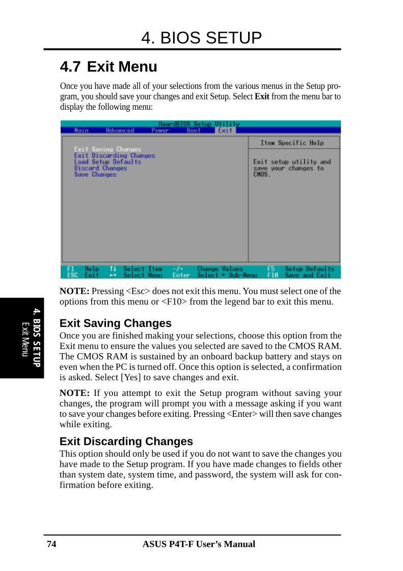
ASUS P4T-F User’s Manual74
4. BIOS SETUP
4. BIO
S SETUP
Exit Menu
4.7 Exit MenuOnce you have made all of your selections from the various menus in the Setup pro-gram, you should save your changes and exit Setup. Select Exit from the menu bar todisplay the following menu:
NOTE: Pressing <Esc> does not exit this menu. You must select one of theoptions from this menu or <F10> from the legend bar to exit this menu.
Exit Saving ChangesOnce you are finished making your selections, choose this option from theExit menu to ensure the values you selected are saved to the CMOS RAM.The CMOS RAM is sustained by an onboard backup battery and stays oneven when the PC is turned off. Once this option is selected, a confirmationis asked. Select [Yes] to save changes and exit.
NOTE: If you attempt to exit the Setup program without saving yourchanges, the program will prompt you with a message asking if you wantto save your changes before exiting. Pressing <Enter> will then save changeswhile exiting.
Exit Discarding ChangesThis option should only be used if you do not want to save the changes youhave made to the Setup program. If you have made changes to fields otherthan system date, system time, and password, the system will ask for con-firmation before exiting.

ASUS P4T-F User’s Manual 75
4. BIOS SETUP
4 . B
IOS
SETU
P
Load Setup DefaultsThis option allows you to load the default values for each of the parameterson the Setup menus. When this option is selected or if <F5> is pressed, aconfirmation is requested. Select [Yes] to load default values. You can nowselect Exit Saving Changes or make other changes before saving the val-ues to the non-volatile RAM.
Discard ChangesThis option allows you to discard the selections you made and restore thevalues you previously saved. After selecting this option, a confirmation isrequested. Select [Yes] to discard any changes and load the previously savedvalues.
Save ChangesThis option saves your selections without exiting the Setup program. Youcan then return to other menus and make changes. After selecting this op-tion, all selections are saved and a confirmation is requested. Select [Yes]to save any changes to the non-volatile RAM.

ASUS P4T-F User’s Manual76
4. BIOS SETUP
4. BIO
S SETUP
(This page was intentionally left blank.)

77ASUS P4T-F User’s Manual
5. S
/W S
ETU
PIn
stal
l OS
5. SOFTWARE SETUP5.1 Install Operating SystemYou should always use the latest operating system and updates when using newhardware to ensure full compliancy. You may use any version of Windows 98/2000/Millenium, but for Windows 95, you must use OSR 2.0 or later. For Windows NT4.0, you must use Service Pack 3.0 or later.
5.2 Start WindowsWhen you start Windows 98 for the first time after installing your motherboard,Windows will detect all plug-and play devices. Follow the Add New Hardware Wiz-ard to install all necessary device drivers. When prompted to restart, select No andthen follow the setup procedures in this section.
NOTE: Because there are various motherboard settings, options, and expansioncards, the following can only be used as a general reference and may not be an exactreflection of your system.

78
5. SOFTWARE SETUP
ASUS P4T-F User’s Manual
5. S/W
SE
TUP
5.3 P4T-F Motherboard Support CDNOTE: The support CD contents are subject to change at any time without notice.
To begin using your support CD disc, just insert it into your CD-ROM drive and thesupport CD installation menu should appear. If the menu does not appear, double-click or run E:\ASSETUP.EXE (assuming that your CD-ROM drive is drive E:).
5.3.1 Installation Menu
• INF Update Utility for Intel 850 Chipset: Installs INF files in Windows for thefollowing items: System and Graphics, LPC Interface, SM Bus, PCI Bridge,Bus Master IDE, USB Host, and Controllers.
• Intel Ultra ATA Storage Driver: Installs Intel’s storage driver.• Intel AC’97 Audio Controller - SigmaTel Codec: Installs Intel’s audio driver.• ASUS PC Probe Vx.xx: Installs a utility to monitor your computer’s fan,
temperature, and voltages.• ASUS Update Vx.xx: Installs a program to help you update your BIOS or
download a BIOS image file.• Microsoft DirectX x.x Driver: Installs Microsoft DirectX driver.• PC-cillin 2000 Vx.xx: Installs the PC-cillin virus protection software. View the
online help for more information.• Adobe Acrobat Reader Vx.x: Installs the Adobe Acrobat Reader software nec-
essary to view user’s manuals saved in PDF format. Updated or other languageversions of this motherboard's manual is available in PDF format at any of ourweb sites.
• Cyberlink Video and Audio Applications: Installs Cyberlink PowerPlayer SEand Cyberlink VideoLive Mail.
• ASUS Screen Saver: Installs the ASUS screen saver.
(TO SEE THE FOLLOWING ITEMS, CLICK RIGHT ARROW ON THE LOWER-RIGHT CORNER OF THE MAIN MENU)
Support C
D

79
5. SOFTWARE SETUP
ASUS P4T-F User’s Manual
5. S
/W S
ETU
P
• Show Motherboard Information: Allows you to view information about yourmotherboard, such as product name, BIOS version, and CPU.
• Browse Support CD: Allows you to view the contents of the CD.• ReadMe: Allows you to view the support CD file list and contact information.• Exit: Exits the CD installation menu.
(TO RETURN TO THE MAIN MENU, CLICK LEFT ARROW ON THE LOWER-RIGHT CORNER OF THE SECONDARY MENU)
Sup
port
CD
5.3.2 Installation ProcedureOn the Installation Items Menu, click on the name of the driver or program groupto initiate installation. Follow the instructions that appear on the setup screens.All drivers and programs will install automatically. Refer to the Software Referencesection for software operating instructions.

80
5. SOFTWARE SETUP
ASUS P4T-F User’s Manual
5. S/W
SE
TUP
(This page was intentionally left blank.)

ASUS P4T-F User’s Manual 81
6. S
/W R
EFER
ENCE
AS
US
PC
Pro
be
6.1 ASUS PC ProbeASUS PC Probe is a convenient utility to continuously monitor your com-puter system’s vital components, such as fan rotations, voltages, and tem-peratures. It also has a utility that lets you review useful information aboutyour computer, such as hard disk space, memory usage, and CPU type, CPUspeed, and internal/external frequencies through the DMI Explorer.
6.1.1 Starting ASUS PC ProbeWhen ASUS PC Probe starts, a splash screen appears allowing you to selectwhether to show the screen again when you open PC Probe or not. To by-pass this startup screen, clear the Show up in next execution check box.
To open ASUS PC Probe, click the Windows Start button, point to Pro-grams, and then ASUS Utility, and then click Probe Vx.xx.
The PC Probe icon will appear on the taskbar’s system tray indicatingthat ASUS PC Probe is running. Clicking the icon will allow you to see thestatus of your PC.
6. SOFTWARE REFERENCE

ASUS P4T-F User’s Manual82
6. SOFTWARE REFERENCE6.1.2 Using ASUS PC ProbeMonitoringMonitor SummaryShows a summary of the items beingmonitored.
Temperature MonitorShows the PC’s temperature (forsupported processors only).
Temperature Warningthreshold adjustment
(Move the slider up to increase thethreshold level or down to decrease
the threshold level)
Fan MonitorShows the PC’s fan rotation.
Voltage MonitorShows the PC’s voltages.
Fan Warningthreshold adjustment
(Move the slider up to increase thethreshold level or down to decrease
the threshold level)6. S/W
REFERENCEA
SU
S P
C P
robe
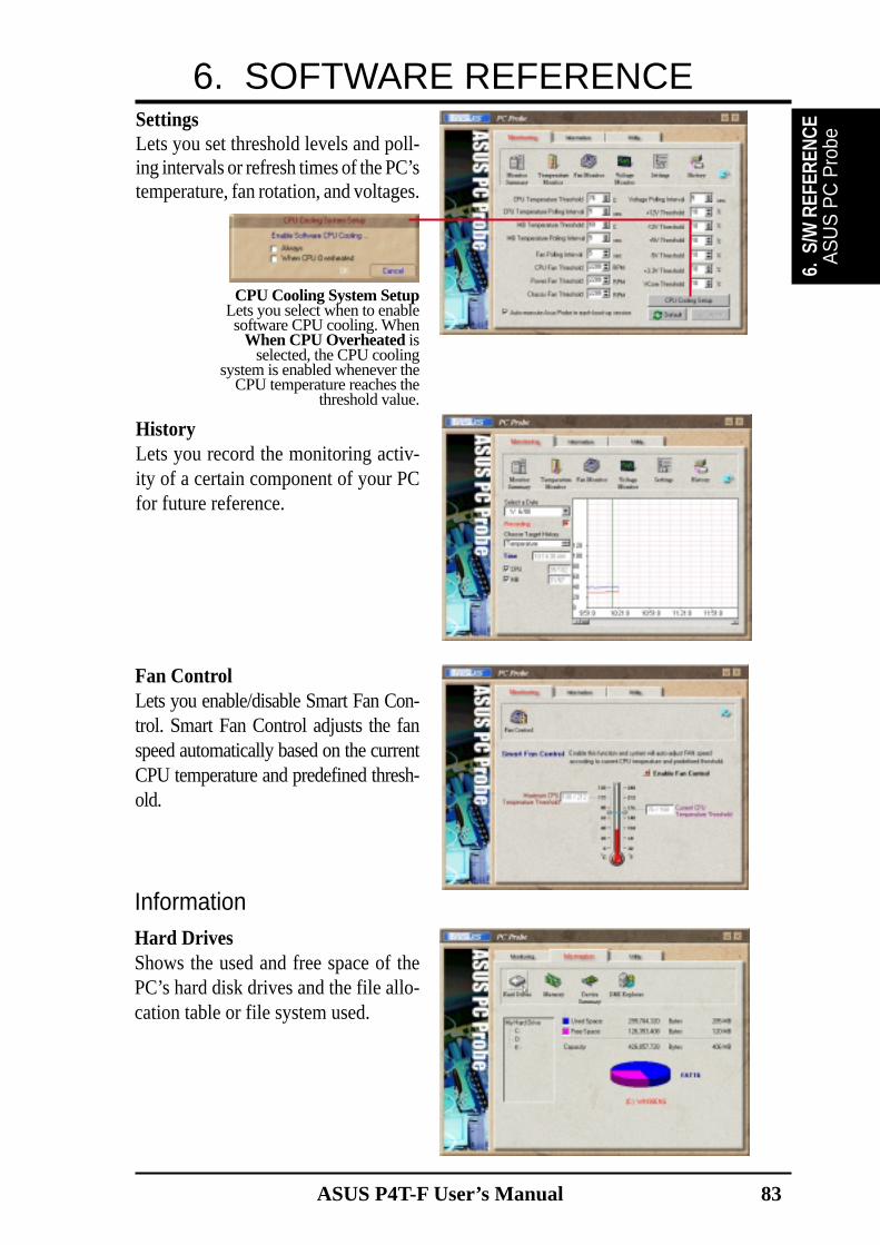
ASUS P4T-F User’s Manual 83
6. SOFTWARE REFERENCE
6. S
/W R
EFER
ENCE
AS
US
PC
Pro
be
SettingsLets you set threshold levels and poll-ing intervals or refresh times of the PC’stemperature, fan rotation, and voltages.
HistoryLets you record the monitoring activ-ity of a certain component of your PCfor future reference.
InformationHard DrivesShows the used and free space of thePC’s hard disk drives and the file allo-cation table or file system used.
Fan ControlLets you enable/disable Smart Fan Con-trol. Smart Fan Control adjusts the fanspeed automatically based on the currentCPU temperature and predefined thresh-old.
CPU Cooling System SetupLets you select when to enablesoftware CPU cooling. When
When CPU Overheated isselected, the CPU cooling
system is enabled whenever theCPU temperature reaches the
threshold value.

ASUS P4T-F User’s Manual84
6. SOFTWARE REFERENCE
Device SummaryShows a summary of devices in your PC.
DMI ExplorerShows information pertinent to the PC,such as CPU type, CPU speed, and in-ternal/external frequencies, and memorysize.
UtilityLets you run programs outside of theASUS Probe modules. To run a program,click Execute Program. NOTE: Thisfeature is currently unavailable.
MemoryShows the PC’s memory load, memoryusage, and paging file usage.
6. S/W REFERENCE
AS
US
PC
Probe

ASUS P4T-F User’s Manual 85
6. SOFTWARE REFERENCE6.1.3 ASUS PC Probe Task Bar Icon
Right clicking the PC Probeicon will bring up a menu toopen or exit ASUS PC Probeand pause or resume all sys-tem monitoring.
When the ASUS PC Probesenses a problem with yourPC, portions of the ASUS PCProbe icon changes to red, thePC speaker beeps, and theASUS PC Probe monitor is dis-played.
6. S
/W R
EFER
ENCE
AS
US
PC
Pro
be

ASUS P4T-F User’s Manual86
6. SOFTWARE REFERENCE6.2 ASUS Live UpdateASUS LiveUpdate is a utility that allows you to update your motherboard’sBIOS and drivers. The use of this utility requires that you are properly con-nected to the Internet through an Internet Service Provider (ISP).
1. Start ASUS UpdateLaunch the utility from Start | Programs | ASUSUtility | ASUS Update Vx.xx.
2. Select an update method.
3. If you selected updating/downloading from theInternet, you will need to select an Internet site.Choose the site that is closest to you or clickAuto Select.
If you selected Update from a file, you willbe prompted to locate the file.
6. S/W REFERENCE
AS
US
Update

ASUS P4T-F User’s Manual 87
6. SOFTWARE REFERENCE
6. S
/W R
EFER
ENCE
Cyb
erlin
k
6.3 CyberLink PowerPlayer SECyberLink PowerPlayer SE is an intelligent software player that can automaticallydetect and playback all kinds of video/audio files, CD and MP3 files as well. This isthe only software you need for all types of video and audio files. No need to wastetime identifying your file types.
6.3.1 Starting CyberLink PowerPlayer SETo start CyberLink Power Player, click the Windows Start button, point to Pro-grams, and then CyberLink PowerPlayer SE, and then click PowerPlayer.
6.3.2 CyberLink PowerPlayer Control Panel
Power Off
H e l pE jec tMin im ize
Z o o m
A b o u t
Backstep Frame
Backward Scan
S t o p
Forward Scan
Step Frame
N e x tPrev ious
S t o p
Conf igurat ioni -Power !
CD ModeShuff le
P l a y
Increase VolumeM u t eDecrease Volume
Karaoke Next angle Next audio stream Next subtitle Add bookmark
Capture frame G o - U p R e p e a t M e n u Go to bookmark

ASUS P4T-F User’s Manual88
6. SOFTWARE REFERENCE
6. S/W REFERENCE
Cyberlink
6.4 CyberLink VideoLive MailCyberLink’s VideoLive Mail Plus Ver 3.0 (a.k.a. VLM 3) is a convenient and excel-lent way to create professional quality video mails from PC video/audio input de-vices and to send the mails to any recipients via VLM 3’s built-in e-mail systemthrough the Internet. VLM 3’s mails comprise video, sound, or snapshot informa-tion; and thus may convey the most profound information to target audiences. It isvery convenient for mail recipients who do not need to install additional softwarecomponent in order to view VLM 3 mails.
VLM 3 works as a very applicant sales tool. It efficiently delivers profound and liveproduct information to your target customers without costing a fortune. VLM 3 alsohelps corporate managers easily give vivid speeches and broadcast through corpo-rate E-mail system. For personal or home users, VLM 3 easily records live videoclips allowing users to send them to friends or family members across the Internet.
VLM 3 loads video messages from PC cameras, digital camcorders, analog camcordervia video capture cards, or from an existing AVI video clips, and captures audiomessages from PC microphones. Video and audio messages are encoded at a veryhigh compressed rate in a real-time mode. From data input, data conversion, tosending video mails via Internet, or saving data to disks, the whole procedure isdone in an easy and continuous process.
VLM 3’s video clip compression rate is up to 1:900, and its playback rate is up to 30frame per second. VLM 3 provides CIF (352 x 288 pixel) display resolution, andsupport true color configuration. A one-minute video mail with QCIF (176 x 144)resolution takes up less than 500KB of memory, making it easy to transmit and savemail. Users may always adjust resolution and recording parameters for differentpurpose.
VLM 3 supports all the hardware devices that are compliant with Video for Win-dows standard. Video for Windows is a well-accepted and well-tested standard. Thus,users do not have to worry about compatibility issues.

ASUS P4T-F User’s Manual 89
6. SOFTWARE REFERENCE
6. S
/W R
EFER
ENCE
Cyb
erlin
k6.4.2 CyberLink VideoLive Mail User Interface
6.4.1 Starting VideoLive MailTo start VideoLive Mail, click the Windows Start button, point to Programs, andthen CyberLink VideoLive Mail, and then click VideoLive Mail x.x. VLM 3’sSetup Wizard will start and guide you through configuring the video and audio inputperipherals and to setup the e-mail environment.
1. Setup Wizard first will prompt a dialog to confirm that you want to configurethe hardware and E-mail setting. Click Yes to continue the system parameterconfiguration.
2. The e-mail configuration screen appears. You will need to enter your name andthe e-mail address. Click Next to continue.
3. The Internet e-mail configuration screen appears. You may choose to use theVLM 3 built-in E-mail functionality (SMTP mail), or use MAPI compliant e-mail system. Consult your ISP or MIS staff for the E-mail server IP address ifyou are not sure. Click Next to continue.
4. Then the Video Configuration screen shows up. You may have to specify thevideo driver for VLM 3, if there are several video-input devices installed. Thenconfigure the number of video frames to be captured per second. Note that themore frames you choose, the bigger the file size will be. Click Next to continue.
5. Then the Setup Wizard will then search for the GSM CODECS module for au-dio compression, and prompt you with the result. Click Next to continue.
6. Setup Wizard then tests the audio volume during playing and recording. ClickNext when ready.
7. Configuration done. Click Finish to complete the environmental setting proce-dure.
Start Playback
Pause
Stop Recording / Playback
Start RecordingVideo Configuration
Snapshot to File
ExitMinimize
Increase MIC volumeDecrease MIC volumeIncrease speaker volumeDecrease speakervolume
Video Mail Wizard
Send Mail
Save Video File
Load Video File
Help
Send Mail

ASUS P4T-F User’s Manual90
6. SOFTWARE REFERENCE
6. S/W REFERENCE
Cyberlink
(This page ws intentionally left blank.)

ASUS P4T-F User’s Manual 91
7 . A
PPEN
DIX
Glos
sary
7. APPENDIX7.1 Glossary13941394 is the IEEE designation for a high performance serial bus tht offers data trans-fers at 100/200/400 Mbps. This serial bus defines both a back plane physical layerand a point-to-point cable-connected virtual bus. The primary application of thecable version is the integration of I/O connectivity at the back panel of personalcomputers using a low-cost, scalable, high-speed serial interface. The 1394 standardalso provides new services such as live connect/disconnect capability for externaldevices including disk drives, printers and hand-held peripherals such as scannersand cameras. This is a new standard to complement the slower USB interface and tocompete with the more expensive SCSI interface.AC97 (Audio Codec '97)AC '97 is the next step in enabling PCs with audio quality comparable to consumerelectronics devices. The specification defines new cost-effective options to help in-tegrate the components necessary to support next-generation auto-intensive PC ap-plications such as DVD, 3-D multiplayer gaming and interactive music. The speci-fication also defines new extensions supporting modem and docking to help bothdesktop and mobile manufacturers adopt these new technologies more quickly andcost-effectively. This specification uses software emulation to compete with the PCISoundBlaster specification.ACPI (Advanced Configuration and Power Interface)The ACPI specification defines a cross-platform interface designed to support manyoperating systems. ACPI defines a flexible and abstract hardware interface that pro-vides a standard way to integrate power management features throughout a PC sys-tem, including hardware, operating system and application software. This enablesthe system to automatically turn ON and OFF peripherals such as CD-ROMs, net-work cards, hard disk drives, and printers, as well as consumer devices connected tothe PC such as VCRs, TVs, phones, and stereos. With this technology, peripheralswill also be able to activate the PC. For example, inserting a tape into a VCR canturn on the PC, which could then activate a large-screen TV and high-fidelity soundsystem.AGP (Accelerated Graphics Port)An interface specification that enables high-performance 3D graphics on mainstreamPCs. AGP was designed to offer the necessary bandwidth and latency to performtexture mapping directly from system memory.
Bus Bus Frequency Bandwidth Data Transfer Rate
PCI 33MHz 33MHz 133MByte/secAGP 1X 66MHz 66MHz 266MByte/secAGP 2X 66MHz 133MHz 512MByte/secAGP 4X 66MHz 266MHz 1024MByte/sec
BIOS (Basic Input/Output System)BIOS is a set of routines that affect how the computer transfers data between com-puter components, such as memory, disks, and the display adapter. The BIOS in-structions are built into the computer’s read-only memory. BIOS parameters can beconfigured by the user through the BIOS Setup program. The BIOS can be updatedusing the provided utility to copy a new BIOS file into the EEPROM.Bit (Binary Digit)Represents the smallest unit of data used by the computer. A bit can have one of twovalues: 0 or 1.

ASUS P4T-F User’s Manual92
7. APPENDIX
7. APPEN
DIX
Glossary
BootBoot means to start the computer operating system by loading it into system memory.When the manual instructs you to “boot” your system (or computer), it means toturn ON your computer. “Reboot” means to restart your computer. When using Win-dows 95 or later, selecting “Restart” from “Start | Shut Down...” will reboot yourcomputer.Bus Master IDEPIO (Programmable I/O) IDE requires that the CPU be involved in IDE access andwaiting for mechanical events. Bus master IDE transfers data to/from the memorywithout interrupting the CPU. Bus master IDE driver and bus master IDE hard diskdrives are required to support bus master IDE mode.Byte (Binary Term)One byte is a group of eight contiguous bits. A byte is used to represent a singlealphanumeric character, punctuation mark, or other symbol.COM PortCOM is a logical device name used by to designate the computer serial ports. Point-ing devices, modems, and infrared modules can be connected to COM ports. EachCOM port is configured to use a different IRQ and address assignment.Concurrent PCIConcurrent PCI maximizes system performance with simultaneous CPU, PCI andISA bus activities. It includes multi-transaction timing, enhanced write performance,a passive release mechanism and support for PCI 2.1 compliant delayed transac-tions. Concurrent PCI provides increased bandwidth, reduced system latencies, im-proves video and audio performance, and improves processing of host based appli-cations.CPU (Central Processing Unit)The CPU, sometimes called “Processor,” actually functions as the “brain” of thecomputer. It interprets and executes program commands and processes data storedin memory. Currently, there are socket 370 (for Pentium III FC-PGA and Celeron-PPGA), socket 7 (for Pentium, AMD, Cyrix, IBM), slot 1 (for Pentium II and III),slot 2 (for Xeon), and slot A (for AMD) processors.Device DriverA device driver is a special set of instructions that allows the computer’s operatingsystem to communicate with devices such as VGA, audio, printer, or modem.DOS (Disk Operating System)DOS is the foundation on which all other programs and software applications oper-ate, including Windows. DOS is responsible for allocating system resources such asmemory, CPU time, disk space, and access to peripheral devices. For this reason,DOS constitutes the basic interface between you and your computer.DRAM (Dynamic Random Access Memory)There are several different types of DRAM such as, EDO DRAM (Extended DataOutput DRAM), SDRAM (Synchronous DRAM), and RDRAM (Rambus DRAM).Flash ROMThe flash ROM is designed to be a resident program and can be updated by a spe-cific programming method. Normally, the flash ROM is used for system BIOS whichinitiates hardware devices and sets up necessary parameters for the OS. Since thecontents of flash ROM can be modified, users are able to update the BIOS by them-selves.IDE (Integrated Drive Electronics)IDE devices integrate the drive control circuitry directly on the drive itself, elimi-nating the need for a separate adapter card (in the case for SCSI devices). UltraDMA/33 IDE devices can achieve up to 33MB/Sec transfer.

ASUS P4T-F User’s Manual 93
7 . A
PPEN
DIX
Glos
sary
7. APPENDIXLPT Port (Line Printer Port)Logical device name reserved by DOS for the computer parallel ports. Each LPTport is configured to use a different IRQ and address assignment.MMXA set of 57 new instructions based on a technique called Single Instruction, MultipleData (SIMD), which is built into the new Intel Pentium PP/MT (P55C) and PentiumII (Klamath) CPU as well as other x86-compatible microprocessors. The MMX in-structions are designed to accelerate multimedia and communications applications,such as 3D video, 3D sound, video conference.OnNowThe OnNow design initiative is a comprehensive, system-wide approach to systemand device power control. OnNow is a term for PC that is always ON but appearsOFF and responds immediately to user or other requests. The OnNow design initia-tive involves changes that will occur in the Microsoft Windows operating system,device drivers, hardware, and applications, and also relies on the changes defined inthe Advanced Configuration and Power Interface (ACPI) specification.PC100SDRAM is Intel's goal is to ensure that memory subsystems continue to supportevolving platform requirements and to assure that memory does not become a bottle-neck to system performance. It is especially important to ensure that the PC memoryroadmap evolves together with the performance roadmaps for the processors, I/Oand graphics.PCI Bus (Peripheral Component Interconnect Local Bus)PCI bus is a specification that defines a 32-bit data bus interface. PCI is a standardwidely used by expansion card manufacturers.PCI Bus MasterThe PCI Bus Master can perform data transfer without local CPU help and further-more, the CPU can be treated as one of the Bus Masters. PCI 2.1 supports concur-rent PCI operation to allow the local CPU and bus master to work simultaneously.Plug and Play BIOSThe ISA bus architecture requires the allocation of memory and I/O address, DMAchannels and interrupt levels among multiple ISA cards. However, configuration ofISA cards is typically done with jumpers that change the decode maps for memoryand I/O space and steer the DMA and interrupt signals to different pins on the bus.Further, system configuration files may need to be updated to reflect these changes.Users typically resolve sharing conflicts by referring to documentation provided byeach manufacturer. For the average user, this configuration process can be unreli-able and frustrating. Plug and play (PnP) BIOS eliminates the ISA add-on card hard-ware conflict problem. The PnP BIOS uses a memory block to define and remembereach card's configuration, which allows the user to change the card's IRQs and DMAin BIOS either automatically or manually.POST (Power On Self Test)When you turn ON the computer, it will first run through the POST, a series ofsoftware-controlled diagnostic tests. The POST checks system memory, the mother-board circuitry, the display, the keyboard, the diskette drive, and other I/O devices.PS/2 PortPS/2 ports are based on IBM Micro Channel Architecture. This type of architecturetransfers data through a 16-bit or 32-bit bus. A PS/2 mouse and/or keyboard may beused on ATX motherboards.RDRAM (Rambus DRAM)Developed by Rambus, Inc., this type of memory can deliver up to 1.6GB of dataper second. RDRAM is the first interface standard that can be directly implementedon high performance VLSI components such as, CMOS DRAMs, memory control-lers, and graphics/video ICs.

ASUS P4T-F User’s Manual94
7. APPENDIX
7. APPEN
DIX
Glossary
ROM (Read Only Memory)ROM is nonvolatile memory used to store permanent programs (called firmware)used in certain computer components. Flash ROM (or EEPROM) can be repro-grammed with new programs (or BIOS).SCSI (Small Computer System Interface)High speed multi-threaded I/O interface defined by the X3T9.2 committee of theAmerican National Standards Institute (ANSI) for connecting many peripheral de-vices. The standard started from 10MBytes/sec to 160MBytes/sec available today.SDRAM (Synchronous DRAM)The SDRAM features a fully synchronous operation referenced to a positive edgeclock whereby all operations are synchronized at a clock input which enables thecoexistence of high performance and a simple user interface. SDRAM takes memoryaccess away from the CPU's control; internal registers in the chips accept the re-quest, and let the CPU do something else while the data requested is assembled forthe next time the CPU talks to the memory. As they work on their own clock cycle,the rest of the system can be clocked faster. There is a version optimized for videocards, and main memory for motherboards.SPD for SDRAM moduleSerial Presence Detect (SPD) is most like an ID detect for SDRAM module, it usinga EEPROM component on DIMM module for storing module configuration infor-mation inside. The Serial Presence Detect function is implemented using a 2048 bitEEPROM component. This nonvolatile storage device contains data programmedby the DIMM manufacturer that identifies the module type and various SDRAMorganization and timing parameters.SSE (Streaming SIMD Extensions)A set of new instructions added to existing architectures that enables a better visualexperience with an accelerated 3D geometry pipeline and support for new applica-tions, such as real-time video encoding and speech recognition.System DiskA system disk contains the core file of an operating system and is used to boot up theoperating system.UltraDMAUltra DMA/33 is a "synchronous DMA" protocol designed by Intel. This function isincluded into Intel's PIIX4 chipset. The traditional IDE transfer only uses one edgeof the data stroke as the data transfer. Ultra DMA/33 uses both edges of data strobewhen the data is transferred. Hence, the data transfer rate is double of the PIO mode4 or DMA mode 2 (16.6MB/s x2 = 33MB/s) on ATA-2 devices.Ultra ATA/66, also known as Ultra DMA/66, is an extension of current Ultra ATA/33 interface. This new high-speed interface has doubled the Ultra ATA/33 burst datatransfer rate to 66.6 Mbytes/sec and maximized disk performance under current PCIlocal bus environmentUSB (Universal Serial Bus)A 4-pin serial cable bus that allows up to 127 plug and play computer peripheralssuch as keyboard, mouse, joystick, scanner, printer, modem, and monitor to share abandwidth through a host scheduled token based protocol. This allows attaching ordetaching while the host and other peripherals are in operation. Supports synchro-nous and asynchronous transfer types over the same set of wires up to 12Mbit/sec.USB 2.0 provides twice the transfer rate compared to USB 1.0 and competes withthe 1394 standard.Wake-On-LANComputer will automatically wake-up upon receiving a wake-up packet through aNetwork interface when it is under power soft-off, suspend or sleep mode.

ASUS P4T-F User’s Manual 95
INDEXA
AC PWR Loss Restart 70Accelerated Graphics Port 30Accessories. See also LeadsAGP 30AGP Slots 30ASUS PC Probe
Using 81ASUS Update
Using 86ATAPI CD-ROM 72ATX Power Switch Lead 41Automatic Power Up 71
B
BIOSBeep Code 43Shadow Configuration 67System Hangup 60
BIOS Beep Codes 43Boot Sequence 72Boot Up Floppy Seek 73Boot Up NumLock Status 56Boot Virus Detection 73
C
Central Processing Unit 25Central Processing Unit (CPU)
External Frequency 19, 22CHS Capacity 55COM 2 Bracket 33Connectors
Floppy Disk Drive 34IDE 35Infrared Module 15, 39Internal Audio 15, 37Parallel Port 33PS/2 Keyboard 32PS/2 Mouse 32Serial Port 33
USB 33CPU Speed 58CPU Temperature 71CyberLink
PowerPlayer SE 87VideoLive Mail 88
CyberLink PowerPlayer SEUsing 87
CyberLink VideoLive MailUsing 88
Cylinders 54
D
DIP Switches 18Discard Changes 75
E
ECP DMA Select 64Exit Discarding Changes 74Exit Saving Changes 74Expansion Cards
AGP Pro 30Assigning IRQs 29
F
Floppy 3 Mode Support 52Floppy Disk Drive Connector 34
G
Glossary 91
H
Halt On 57Hardware Setup
CPU Installation 25Procedure 16
Head 55Headers
USB 37, 38

96 ASUS P4T-F User’s Manual
INDEXI
IDE Activity LED Lead 15, 39IDE Connectors 35IDE Hard Drive 72Infrared Module Connector 15, 39Installed Memory 57Installing
CPU 25Internal Audio Connector 37Interrupts
Request Table 29Standard Assignments 29
IRQ XX Used By ISA 66
J
JumperFree™ Mode 15, 18
K
Keyboard Lock Switch Lead 41
L
LANJumper Setting 21
Language 57Leads
IDE Activity LED 39Legacy Diskette A 52Legacy Diskette B 52Load Setup Defaults 75
M
Maximum LBA Capacity 55MB Temperature 71Memory Hole At 15M-16M 62Motherboard
Settings 17Multi-Sector Transfers 55
O
Onboard AC97 Modem Controlle63, 64
Onboard Parallel Port 64Onboard PCI IDE Enable 62Onboard Serial Port 1 63Onboard Serial Port 2 63OS/2 Onboard Memory > 64M 60Other Boot Device Select 72
P
Parallel Port Connector 33Parallel Port Mode 64PCI Latency Timer 65PCI/VGA Palette Snoop 65PIO Mode 55Plug & Play O/S 73Power Management 68PowerPlayer SE
Using 87Procedures
CPU Installation 25Updating BIOS 46
PS/2 Keyboard Connector 32PS/2 Mouse Connector 32PWR Up On Modem Act 70
Q
Quick Power On Self Test 73
R
Removable Device 72Reset Switch Lead 41
S
Save Changes 75Sector 55

ASUS P4T-F User’s Manual 97
INDEXSerial Port Connectors 33Settings
Onboard Audio 22SMART Monitoring 55
SMI Lead 41Starting Up 43Supervisor Password 57Suspend Mode 69System Date 52System Memory 23System Message LED Lead 41System Power LED Lead 41System Time 52
T
Translation Method 54Type 53
U
UART2 Use Standard Infrared 63Ultra DMA Mode 55Universal Serial Bus Ports 33Updating Your BIOS 45USB Function 65USB Headers 37, 38USB Legacy Support 59Using
ASUS PC Probe 81ASUS Update 86PowerPlayer SE 87
V
VCORE Voltage 71Video ROM BIOS Shadow 67VideoLive Mail 88
Using 88Voltage
+12 71+3.3 71+5 71VCORE 71

98 ASUS P4T-F User’s Manual
NOTES