user manual smart-ups on-line src2kuxi, … manual smart-ups on-line src2kuxi, src3kuxi 2 smart-ups...
TRANSCRIPT
User Manual Smart-UPS™ On-Line SRC2KUXI, SRC3KUXI
Important Safety InformationRead the instructions carefully to become familiar with the equipment before trying to install, operate, service or maintain it. The following special messages may appear throughout this manual or on the equipment to warn of potential hazards or to call attention to information that clarifies or simplifies a procedure.
The addition of this symbol to a Danger or Warning safety label indicates that an electrical hazard exists which will result in personal injury if the instructions are not followed.
This is the safety alert symbol. It is used to alert you to potential personal injury hazards. Obey all safety messages that follow this symbol to avoid possible injury or death.
WARNING
WARNING indicates a potentially hazardous situation which, if not avoided, can result in death or serious injury.
CAUTION
CAUTION indicates a potentially hazardous situation which, if not avoided, can result in minor or moderate injury.
CAUTION
CAUTION addresses practices not related to physical injury including certain environmental hazards, potential damage or loss of data.
Safety and General InformationInspect the package contents upon receipt. Notify the carrier and dealer if there is any damage.
• This UPS is for indoor use only.
• Do not operate this UPS in direct sunlight, in contact with fluids, or where there is excessive dust or high humidity.
• Do not operate the UPS near open windows or doors.
• Be sure the air vents on the UPS are not blocked. Allow adequate space for proper ventilation.Note: Allow a minimum of 20 cm clearance on both front and rear sides of the UPS.
• Environmental factors impact battery life. Elevated ambient temperatures, poor quality utility power, and frequent discharges will shorten battery life. Follow the battery manufacturer recommendations.
Electrical safety
• Connection to the branch circuit (mains) must be performed by a qualified electrician.
• The protective earth conductor for the UPS carries the leakage current from the load devices (computer equipment). An insulated ground conductor is to be installed as part of the branch circuit that supplies the UPS. The conductor must have the same size and insulation material as the grounded and ungrounded branch circuit supply conductors. The conductor will be green and with or without a yellow stripe.
• The grounding conductor is to be grounded to earth at the service equipment, or if supplied by a separately derived system, at the supply transformer or motor generator set.
Battery safety
• Before installing or replacing the batteries, remove jewelry such as wristwatches and rings. High short circuit current through conductive materials could cause severe burns.
• Do not dispose of batteries in a fire. The batteries may explode.
• Do not open or mutilate batteries. Released electrolyte is harmful to the skin and eyes, and may be toxic.
Smart-UPS On-Line SRC2KUXI, SRC3KUXI2
Hardwiring safety
• Verify that all branch circuit (mains) and low voltage (control) circuits are deenergized, and locked out before installing cables or making connections, whether in the junction box or to the UPS.
• Wiring by a qualified electrician is required.
• Check national and local codes before wiring.
• Strain relief is required for all hardwiring.
• All openings allowing access to UPS hardwiring terminals must be covered. Failure to do so may result in personal injury or equipment damage.
• Select wire size and connectors according to national and local codes.
Product DescriptionThe APC by Schneider Electric Smart-UPS™ is a high performance uninterruptible power supply (UPS). The UPS helps to protect the connected electronic equipment from utility power blackouts, brownouts, sags, surges, small utility power fluctuations and large disturbances. The UPS also provides battery backup power for connected equipment until utility power returns to normal levels or the batteries are discharged.
Parallel redundancy
Install two identical UPSs with SRCPK0203 parallel system to get a redundant system. The redundant system helps to keep the load (connected equipment) powered even when one UPS is not working.
Note: Parallel system SRCPK0203 works with only two identical UPS models of SRC2KUXI or SRC3KUXI.
This user manual is available on the APC Web site, www.apc.com.
Smart-UPS On-Line SRC2KUXI, SRC3KUXI 3
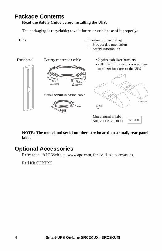
Package ContentsRead the Safety Guide before installing the UPS.
The packaging is recyclable; save it for reuse or dispose of it properly.:
NOTE: The model and serial numbers are located on a small, rear panel label.
Optional AccessoriesRefer to the APC Web site, www.apc.com, for available accessories.
Rail Kit SURTRK
• UPS • Literature kit containing:– Product documentation– Safety information
Front bezel Battery connection cable • 2 pairs stabilizer brackets• 4 flat head screws to secure tower stabilizer brackets to the UPS
Model number label SRC2000/SRC3000
Serial communication cable
gen1078b
suo0856a
SRC3000
Smart-UPS On-Line SRC2KUXI, SRC3KUXI4
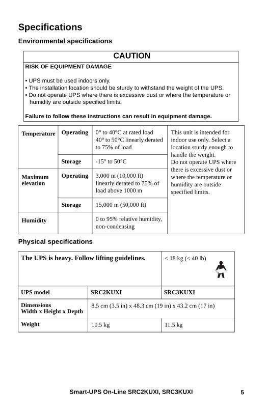
SpecificationsEnvironmental specifications
Physical specifications
CAUTIONRISK OF EQUIPMENT DAMAGE
• UPS must be used indoors only.• The installation location should be sturdy to withstand the weight of the UPS.• Do not operate UPS where there is excessive dust or where the temperature or
humidity are outside specified limits.
Failure to follow these instructions can result in equipment damage.
Temperature Operating 0° to 40°C at rated load 40° to 50°C linearly derated to 75% of load
This unit is intended for indoor use only. Select a location sturdy enough to handle the weight.Do not operate UPS where there is excessive dust or where the temperature or humidity are outside specified limits.
Storage -15° to 50°C
Maximum elevation
Operating 3,000 m (10,000 ft)linearly derated to 75% of load above 1000 m
Storage 15,000 m (50,000 ft)
Humidity 0 to 95% relative humidity, non-condensing
The UPS is heavy. Follow lifting guidelines. < 18 kg (< 40 lb)
UPS model SRC2KUXI SRC3KUXI
Dimensions Width x Height x Depth
8.5 cm (3.5 in) x 48.3 cm (19 in) x 43.2 cm (17 in)
Weight 10.5 kg 11.5 kg
Smart-UPS On-Line SRC2KUXI, SRC3KUXI 5
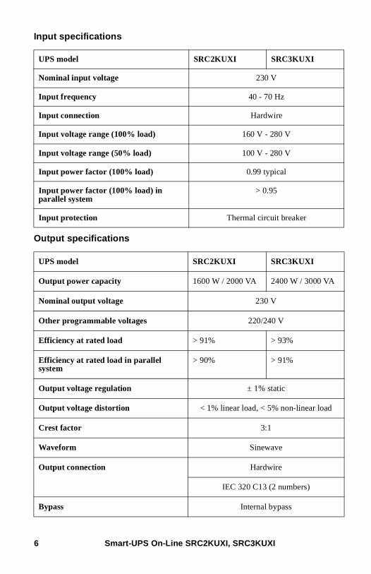
Input specifications
Output specifications
UPS model SRC2KUXI SRC3KUXI
Nominal input voltage 230 V
Input frequency 40 - 70 Hz
Input connection Hardwire
Input voltage range (100% load) 160 V - 280 V
Input voltage range (50% load) 100 V - 280 V
Input power factor (100% load) 0.99 typical
Input power factor (100% load) in parallel system
> 0.95
Input protection Thermal circuit breaker
UPS model SRC2KUXI SRC3KUXI
Output power capacity 1600 W / 2000 VA 2400 W / 3000 VA
Nominal output voltage 230 V
Other programmable voltages 220/240 V
Efficiency at rated load > 91% > 93%
Efficiency at rated load in parallel system
> 90% > 91%
Output voltage regulation ± 1% static
Output voltage distortion < 1% linear load, < 5% non-linear load
Crest factor 3:1
Waveform Sinewave
Output connection Hardwire
IEC 320 C13 (2 numbers)
Bypass Internal bypass
Smart-UPS On-Line SRC2KUXI, SRC3KUXI6
Battery charger
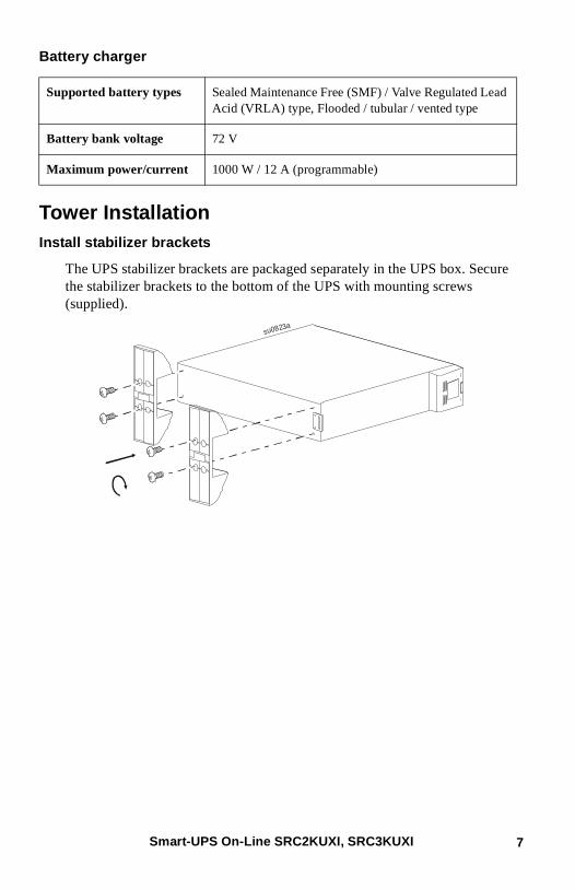
Tower InstallationInstall stabilizer brackets
The UPS stabilizer brackets are packaged separately in the UPS box. Secure the stabilizer brackets to the bottom of the UPS with mounting screws (supplied).
Supported battery types Sealed Maintenance Free (SMF) / Valve Regulated Lead Acid (VRLA) type, Flooded / tubular / vented type
Battery bank voltage 72 V
Maximum power/current 1000 W / 12 A (programmable)
su0823a
Smart-UPS On-Line SRC2KUXI, SRC3KUXI 7
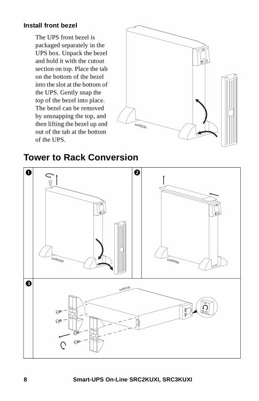
Install front bezel
The UPS front bezel is packaged separately in the UPS box. Unpack the bezel and hold it with the cutout section on top. Place the tab on the bottom of the bezel into the slot at the bottom of the UPS. Gently snap the top of the bezel into place. The bezel can be removed by unsnapping the top, and then lifting the bezel up and out of the tab at the bottom of the UPS.
Tower to Rack Conversion
su0816c
su0816d su0949a
su0823b
Smart-UPS On-Line SRC2KUXI, SRC3KUXI8
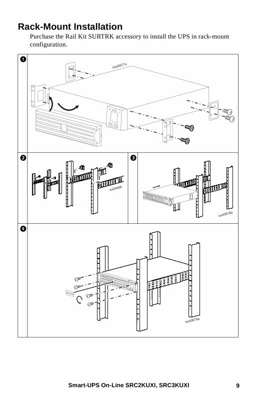
Rack-Mount InstallationPurchase the Rail Kit SURTRK accessory to install the UPS in rack-mount configuration.
suo0877a
su0940b
suo0878a
suo0879a
Smart-UPS On-Line SRC2KUXI, SRC3KUXI 9
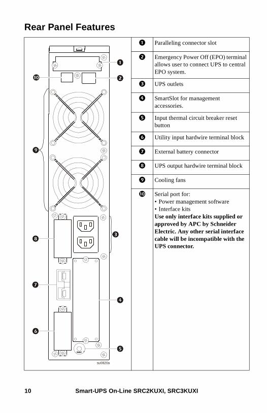
Rear Panel Features
Paralleling connector slot
Emergency Power Off (EPO) terminal allows user to connect UPS to central EPO system.
UPS outlets
SmartSlot for management accessories.
Input thermal circuit breaker reset button
Utility input hardwire terminal block
External battery connector
UPS output hardwire terminal block
Cooling fans
Serial port for:• Power management software• Interface kitsUse only interface kits supplied or approved by APC by Schneider Electric. Any other serial interface cable will be incompatible with the UPS connector.
su0820a
Smart-UPS On-Line SRC2KUXI, SRC3KUXI10
Installation
Units may vary in appearance from those depicted in this manual.See “Physical specifications” on page 5 in this manual and the Safety Guide before installing units.
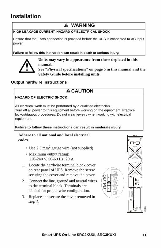
Output hardwire instructions
Adhere to all national and local electrical codes.
• Use 2.5 mm2 gauge wire (not supplied)
• Maximum output rating: 220-240 V, 50-60 Hz, 20 A
1. Locate the hardwire terminal block cover on rear panel of UPS. Remove the screw securing the cover and remove the cover.
2. Connect the line, ground and neutral wires to the terminal block. Terminals are labeled for proper wire configuration.
3. Replace and secure the cover removed in step 1.
WARNINGHIGH LEAKAGE CURRENT, HAZARD OF ELECTRICAL SHOCK
Ensure that the Earth connection is provided before the UPS is connected to AC input power.
Failure to follow this instruction can result in death or serious injury.
CAUTIONHAZARD OF ELECTRIC SHOCK
All electrical work must be performed by a qualified electrician.Turn off all power to this equipment before working on the equipment. Practice lockout/tagout procedures. Do not wear jewelry when working with electrical equipment.
Failure to follow these instructions can result in moderate injury.
su081
9b
OU
TP
UT
Smart-UPS On-Line SRC2KUXI, SRC3KUXI 11
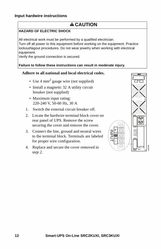
Input hardwire instructions
Adhere to all national and local electrical codes.
• Use 4 mm2 gauge wire (not supplied)
• Install a magnetic 32 A utility circuit breaker (not supplied)
• Maximum input rating: 220-240 V, 50-60 Hz, 30 A
1. Switch the external circuit breaker off.
2. Locate the hardwire terminal block cover on rear panel of UPS. Remove the screw securing the cover and remove the cover.
3. Connect the line, ground and neutral wires to the terminal block. Terminals are labeled for proper wire configuration.
4. Replace and secure the cover removed in step 2.
CAUTIONHAZARD OF ELECTRIC SHOCK
All electrical work must be performed by a qualified electrician.Turn off all power to this equipment before working on the equipment. Practice lockout/tagout procedures. Do not wear jewelry when working with electrical equipment.Verify the ground connection is secured.
Failure to follow these instructions can result in moderate injury.
su08
18b
INP
UT
Smart-UPS On-Line SRC2KUXI, SRC3KUXI12
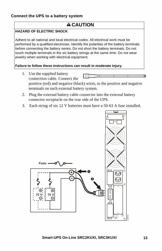
Connect the UPS to a battery system
1. Use the supplied battery connection cable. Connect the positive (red) and negative (black) wires, to the positive and negative terminals on each external battery system.
2. Plug the external battery cable connector into the external battery connector receptacle on the rear side of the UPS.
3. Each string of six 12 V batteries must have a 50-63 A fuse installed.
CAUTIONHAZARD OF ELECTRIC SHOCK
Adhere to all national and local electrical codes. All electrical work must be performed by a qualified electrician. Identify the polarities of the battery terminals before connecting the battery series. Do not short the battery terminals. Do not touch multiple terminals in the six battery strings at the same time. Do not wear jewelry when working with electrical equipment.
Failure to follow these instructions can result in moderate injury.
72 V72 V
Fuse:
su0
82
1c
Smart-UPS On-Line SRC2KUXI, SRC3KUXI 13
Start UpConnect equipment, external batteries and input power to the UPS
1. Connect equipment to UPS (cables not supplied). Avoid using extension cords. See “Output hardwire instructions” on page 11 in this manual.
2. Connect external batteries to UPS. See “Connect the UPS to a battery system” on page 13 in this manual.
3. Connect input utility power to the UPS.
4. Switch the utility input magnetic circuit breaker on. The display panel will illuminate when utility power is available.
Start the UPS
Press the POWER ON/OFF button located on the front panel of UPS.
Cold start the UPS
Use cold start feature to supply power to connected equipment from the UPS batteries.
Press the POWER ON/OFF button. The display panel will illuminate.
Press the POWER ON/OFF button again to supply battery power to the connected equipment.
Install PowerChute™ Software
To install PowerChute Business Edition (PCBE) software, connect the supplied serial cable to the serial port on the UPS and the other end to a computer with access to the Web.
On the computer, go to www.apc.com/tools/download. Select “Software Upgrades - PowerChute Business Edition” in the “Filter by Software/Firmware” drop down menu. Select the appropriate operating system. Follow directions to download the software.
CAUTIONHAZARD OF ELECTRIC SHOCK
All electrical work must be performed by a qualified electrician.Turn off all power to this equipment before working on the equipment. Practice lockout/tagout procedures. Do not wear jewelry when working with electrical equipment.
Failure to follow these instructions can result in moderate injury.
Smart-UPS On-Line SRC2KUXI, SRC3KUXI14
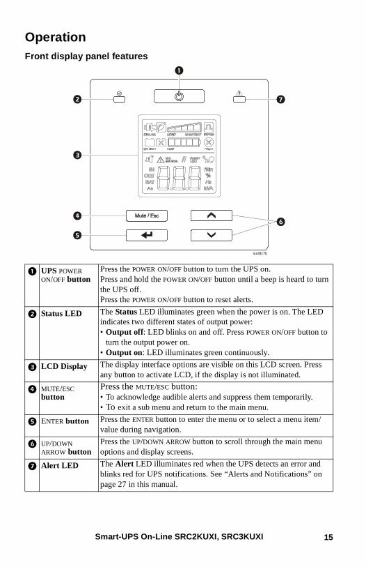
OperationFront display panel features
UPS POWER ON/OFF button
Press the POWER ON/OFF button to turn the UPS on.Press and hold the POWER ON/OFF button until a beep is heard to turn the UPS off.Press the POWER ON/OFF button to reset alerts.
Status LED The Status LED illuminates green when the power is on. The LED indicates two different states of output power:• Output off: LED blinks on and off. Press POWER ON/OFF button to
turn the output power on.• Output on: LED illuminates green continuously.
LCD Display The display interface options are visible on this LCD screen. Press any button to activate LCD, if the display is not illuminated.
MUTE/ESC button
Press the MUTE/ESC button:• To acknowledge audible alerts and suppress them temporarily.• To exit a sub menu and return to the main menu.
ENTER button Press the ENTER button to enter the menu or to select a menu item/value during navigation.
UP/DOWN ARROW button
Press the UP/DOWN ARROW button to scroll through the main menu options and display screens.
Alert LED The Alert LED illuminates red when the UPS detects an error and blinks red for UPS notifications. See “Alerts and Notifications” on page 27 in this manual.
su0817b
Smart-UPS On-Line SRC2KUXI, SRC3KUXI 15
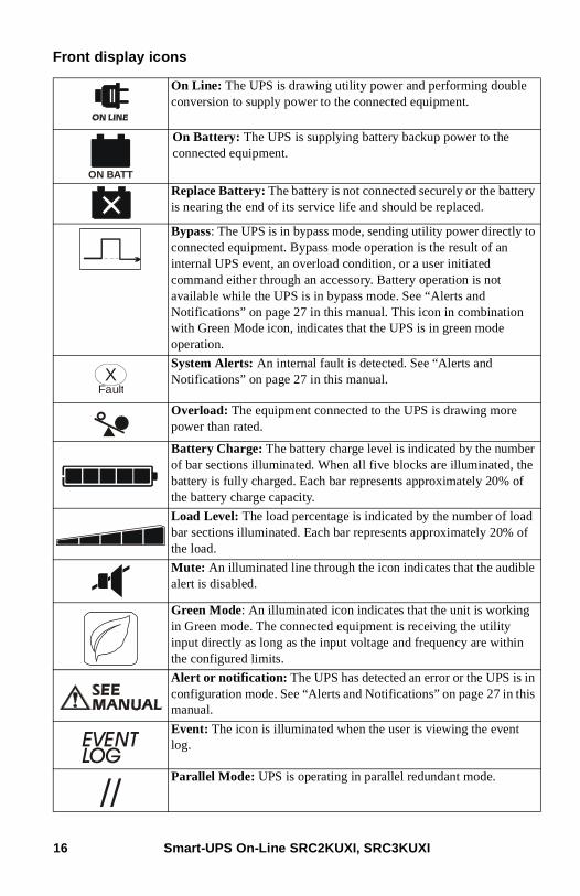
Front display icons
On Line: The UPS is drawing utility power and performing double conversion to supply power to the connected equipment.
On Battery: The UPS is supplying battery backup power to the connected equipment.
Replace Battery: The battery is not connected securely or the battery is nearing the end of its service life and should be replaced.
Bypass: The UPS is in bypass mode, sending utility power directly to connected equipment. Bypass mode operation is the result of an internal UPS event, an overload condition, or a user initiated command either through an accessory. Battery operation is not available while the UPS is in bypass mode. See “Alerts and Notifications” on page 27 in this manual. This icon in combination with Green Mode icon, indicates that the UPS is in green mode operation.
System Alerts: An internal fault is detected. See “Alerts and Notifications” on page 27 in this manual.
Overload: The equipment connected to the UPS is drawing more power than rated.
Battery Charge: The battery charge level is indicated by the number of bar sections illuminated. When all five blocks are illuminated, the battery is fully charged. Each bar represents approximately 20% of the battery charge capacity.
Load Level: The load percentage is indicated by the number of load bar sections illuminated. Each bar represents approximately 20% of the load.
Mute: An illuminated line through the icon indicates that the audible alert is disabled.
Green Mode: An illuminated icon indicates that the unit is working in Green mode. The connected equipment is receiving the utility input directly as long as the input voltage and frequency are within the configured limits.
Alert or notification: The UPS has detected an error or the UPS is in configuration mode. See “Alerts and Notifications” on page 27 in this manual.
Event: The icon is illuminated when the user is viewing the event log.
Parallel Mode: UPS is operating in parallel redundant mode.
ON BATT
FaultX
EVENTLOG
//
Smart-UPS On-Line SRC2KUXI, SRC3KUXI16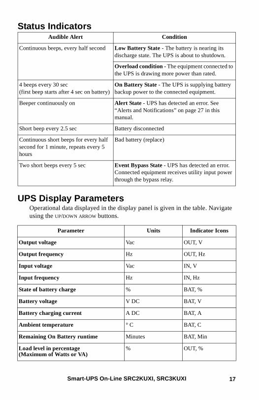
Status Indicators
UPS Display ParametersOperational data displayed in the display panel is given in the table. Navigate using the UP/DOWN ARROW buttons.
Audible Alert Condition
Continuous beeps, every half second Low Battery State - The battery is nearing its discharge state. The UPS is about to shutdown.
Overload condition - The equipment connected to the UPS is drawing more power than rated.
4 beeps every 30 sec (first beep starts after 4 sec on battery)
On Battery State - The UPS is supplying battery backup power to the connected equipment.
Beeper continuously on Alert State - UPS has detected an error. See “Alerts and Notifications” on page 27 in this manual.
Short beep every 2.5 sec Battery disconnected
Continuous short beeps for every half second for 1 minute, repeats every 5 hours
Bad battery (replace)
Two short beeps every 5 sec Event Bypass State - UPS has detected an error. Connected equipment receives utility input power through the bypass relay.
Parameter Units Indicator Icons
Output voltage Vac OUT, V
Output frequency Hz OUT, Hz
Input voltage Vac IN, V
Input frequency Hz IN, Hz
State of battery charge % BAT, %
Battery voltage V DC BAT, V
Battery charging current A DC BAT, A
Ambient temperature ° C BAT, C
Remaining On Battery runtime Minutes BAT, Min
Load level in percentage (Maximum of Watts or VA)
% OUT, %
Smart-UPS On-Line SRC2KUXI, SRC3KUXI 17

ConfigurationUPS settings
Configure UPS settings using the display interface.
Load level in kVA kVA OUT, kVA
Total Ah capacity of connected battery Ah BAT, AH
Connected battery type SF - SMF / VRLAFld - Flooded / Tubular / Vented
BAT
FunctionFactory Default
User Selectable Options Description
Output voltage * 230 Vac 220, 230, 240 Vac Allows the user to select output voltage while the UPS is operating online.
ID setting * ID0 ID0, ID1, ID2 Set to ID0 if the UPS is working as a standalone system.Set to ID1 or ID2 if the UPS is operating in parallel redundant mode.
Audible alert Enable Enable; disable UPS will mute audible alerts when set to disable or when the display panel buttons are pressed.
Bypass voltage - Lower limit
160 V 160 to 220 Allows the user to select voltage below which unit will not transfer to bypass, instead it will drop the load by turning output off. If unit is already in bypass, it will disconnect the bypass and drop the load.
Bypass voltage - Upper limit
264 V 240 to 270 Allows the user to select voltage above which the UPS will not transfer to bypass, instead it will drop the load by turning output off. If unit is already in bypass, it will disconnect the bypass and drop the load.
Parameter Units Indicator Icons
Smart-UPS On-Line SRC2KUXI, SRC3KUXI18
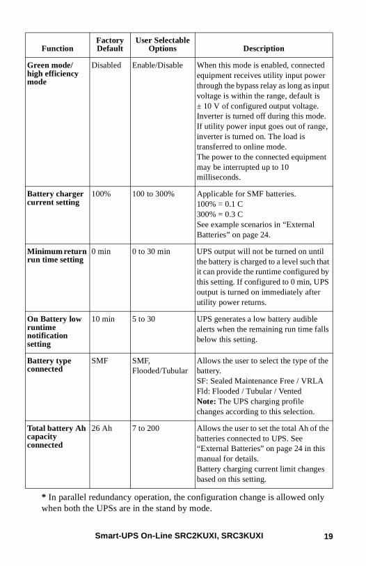
* In parallel redundancy operation, the configuration change is allowed only when both the UPSs are in the stand by mode.
Green mode/high efficiency mode
Disabled Enable/Disable When this mode is enabled, connected equipment receives utility input power through the bypass relay as long as input voltage is within the range, default is ± 10 V of configured output voltage. Inverter is turned off during this mode.If utility power input goes out of range, inverter is turned on. The load is transferred to online mode.The power to the connected equipment may be interrupted up to 10 milliseconds.
Battery charger current setting
100% 100 to 300% Applicable for SMF batteries.100% = 0.1 C300% = 0.3 CSee example scenarios in “External Batteries” on page 24.
Minimum return run time setting
0 min 0 to 30 min UPS output will not be turned on until the battery is charged to a level such that it can provide the runtime configured by this setting. If configured to 0 min, UPS output is turned on immediately after utility power returns.
On Battery low runtime notification setting
10 min 5 to 30 UPS generates a low battery audible alerts when the remaining run time falls below this setting.
Battery type connected
SMF SMF, Flooded/Tubular
Allows the user to select the type of the battery.SF: Sealed Maintenance Free / VRLAFld: Flooded / Tubular / VentedNote: The UPS charging profile changes according to this selection.
Total battery Ah capacity connected
26 Ah 7 to 200 Allows the user to set the total Ah of the batteries connected to UPS. See “External Batteries” on page 24 in this manual for details. Battery charging current limit changes based on this setting.
FunctionFactory Default
User Selectable Options Description
Smart-UPS On-Line SRC2KUXI, SRC3KUXI 19
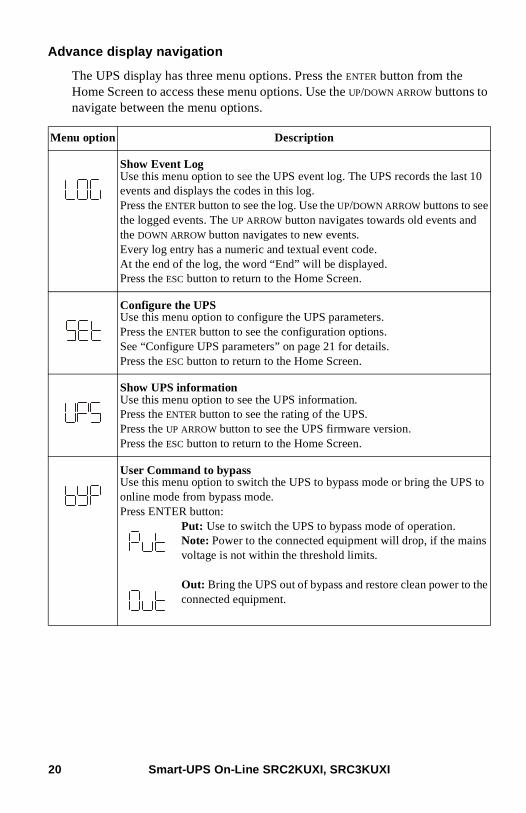
Advance display navigation
The UPS display has three menu options. Press the ENTER button from the Home Screen to access these menu options. Use the UP/DOWN ARROW buttons to navigate between the menu options.
Menu option Description
Show Event Log Use this menu option to see the UPS event log. The UPS records the last 10 events and displays the codes in this log.Press the ENTER button to see the log. Use the UP/DOWN ARROW buttons to see the logged events. The UP ARROW button navigates towards old events and the DOWN ARROW button navigates to new events.Every log entry has a numeric and textual event code.At the end of the log, the word “End” will be displayed.Press the ESC button to return to the Home Screen.
Configure the UPSUse this menu option to configure the UPS parameters.Press the ENTER button to see the configuration options.See “Configure UPS parameters” on page 21 for details.Press the ESC button to return to the Home Screen.
Show UPS informationUse this menu option to see the UPS information.Press the ENTER button to see the rating of the UPS. Press the UP ARROW button to see the UPS firmware version.Press the ESC button to return to the Home Screen.
User Command to bypassUse this menu option to switch the UPS to bypass mode or bring the UPS to online mode from bypass mode.Press ENTER button:
Put: Use to switch the UPS to bypass mode of operation.Note: Power to the connected equipment will drop, if the mains voltage is not within the threshold limits.
Out: Bring the UPS out of bypass and restore clean power to the connected equipment.
Smart-UPS On-Line SRC2KUXI, SRC3KUXI20
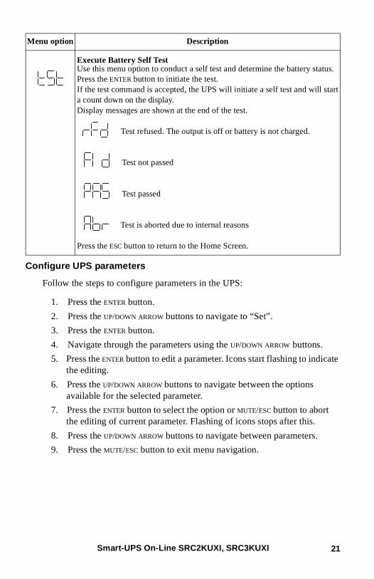
Configure UPS parameters
Follow the steps to configure parameters in the UPS:
1. Press the ENTER button.
2. Press the UP/DOWN ARROW buttons to navigate to “Set”.
3. Press the ENTER button.
4. Navigate through the parameters using the UP/DOWN ARROW buttons.
5. Press the ENTER button to edit a parameter. Icons start flashing to indicate the editing.
6. Press the UP/DOWN ARROW buttons to navigate between the options available for the selected parameter.
7. Press the ENTER button to select the option or MUTE/ESC button to abort the editing of current parameter. Flashing of icons stops after this.
8. Press the UP/DOWN ARROW buttons to navigate between parameters.
9. Press the MUTE/ESC button to exit menu navigation.
Execute Battery Self Test Use this menu option to conduct a self test and determine the battery status.Press the ENTER button to initiate the test.If the test command is accepted, the UPS will initiate a self test and will start a count down on the display.Display messages are shown at the end of the test.
Test refused. The output is off or battery is not charged.
Test not passed
Test passed
Test is aborted due to internal reasons
Press the ESC button to return to the Home Screen.
Menu option Description
Smart-UPS On-Line SRC2KUXI, SRC3KUXI 21
Emergency Power OffThe Emergency Power Off (EPO) option is a feature that will immediately remove power to all connected equipment. When EPO button is pushed, all connected equipment will immediately turn off and will not switch to battery power.
Adhere to all national and local electrical codes. Wiring must be performed by a qualified electrician.
The EPO switch is internally powered by the UPS for use with non-powered switches or potential free contacts.
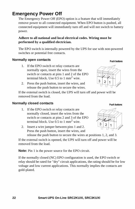
Normally open contacts
1. If the EPO switch or relay contacts are normally open, insert the wires from the switch or contacts at pins 1 and 2 of the EPO terminal block. Use 0.5 to 1 mm2 wire.
2. Press the push button, insert the wires, and release the push button to secure the wires.
If the external switch is closed, the UPS will turn off and power will be removed from the load.
Normally closed contacts
1. If the EPO switch or relay contacts are normally closed, insert the wires from the switch or contacts at pins 2 and 3 of the EPO terminal block. Use 0.5 to 1 mm2 wire.
2. Insert a wire jumper between pins 1 and 2. Press the push button, insert the wires, and release the push button to secure the wires at positions 1, 2, and 3.
If the external switch is opened, the UPS will turn off and power will be removed from the load.
Note: Pin 1 is the power source for the EPO circuit.
If the normally closed (NC) EPO configuration is used, the EPO switch or relay should be rated for "dry" circuit applications, the rating should be for low voltage and low current applications. This normally implies the contacts are gold-plated.
su081
5c
Push buttons
su08
15d
Push buttons
Smart-UPS On-Line SRC2KUXI, SRC3KUXI22
The EPO interface is a Safety Extra Low Voltage (SELV) circuit. Connect it only to other SELV circuits. The EPO interface monitors circuits that have no determined voltage potential. Such closure circuits may be provided by a switch or relay properly isolated from the utility. To avoid damage to the UPS, do not connect the EPO interface to any circuit other than a unused circuit.
Use one of the following cable types to connect the UPS to the EPO switch.
• CL2: Class 2 cable for general use.
• CL2P: Plenum cable for use in ducts, plenums, and other spaces used for environmental air.
• CL2R: Riser cable for use in a vertical run in a floor-to-floor shaft.
• CLEX: Limited use cable for use in dwellings and for use in raceways.
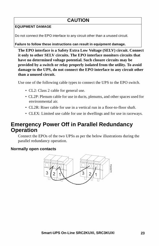
Emergency Power Off in Parallel Redundancy Operation
Connect the EPOs of the two UPSs as per the below illustrations during the parallel redundancy operation.
Normally open contacts
CAUTIONEQUIPMENT DAMAGE
Do not connect the EPO interface to any circuit other than a unused circuit.
Failure to follow these instructions can result in equipment damage.
su09
45a
Smart-UPS On-Line SRC2KUXI, SRC3KUXI 23
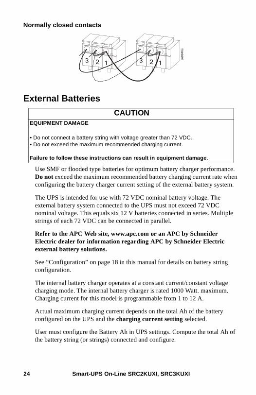
Normally closed contacts
External Batteries
Use SMF or flooded type batteries for optimum battery charger performance. Do not exceed the maximum recommended battery charging current rate when configuring the battery charger current setting of the external battery system.
The UPS is intended for use with 72 VDC nominal battery voltage. The external battery system connected to the UPS must not exceed 72 VDC nominal voltage. This equals six 12 V batteries connected in series. Multiple strings of each 72 VDC can be connected in parallel.
Refer to the APC Web site, www.apc.com or an APC by Schneider Electric dealer for information regarding APC by Schneider Electric external battery solutions.
See “Configuration” on page 18 in this manual for details on battery string configuration.
The internal battery charger operates at a constant current/constant voltage charging mode. The internal battery charger is rated 1000 Watt. maximum. Charging current for this model is programmable from 1 to 12 A.
Actual maximum charging current depends on the total Ah of the battery configured on the UPS and the charging current setting selected.
User must configure the Battery Ah in UPS settings. Compute the total Ah of the battery string (or strings) connected and configure.
CAUTIONEQUIPMENT DAMAGE
• Do not connect a battery string with voltage greater than 72 VDC.• Do not exceed the maximum recommended charging current.
Failure to follow these instructions can result in equipment damage.
su0
946a
Smart-UPS On-Line SRC2KUXI, SRC3KUXI24
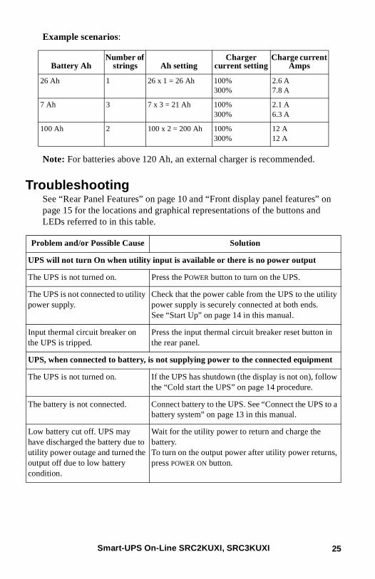
Example scenarios:
Note: For batteries above 120 Ah, an external charger is recommended.
TroubleshootingSee “Rear Panel Features” on page 10 and “Front display panel features” on page 15 for the locations and graphical representations of the buttons and LEDs referred to in this table.
Battery AhNumber of
strings Ah settingCharger
current settingCharge current
Amps
26 Ah 1 26 x 1 = 26 Ah 100%300%
2.6 A7.8 A
7 Ah 3 7 x 3 = 21 Ah 100%300%
2.1 A6.3 A
100 Ah 2 100 x 2 = 200 Ah 100%300%
12 A12 A
Problem and/or Possible Cause Solution
UPS will not turn On when utility input is available or there is no power output
The UPS is not turned on. Press the POWER button to turn on the UPS.
The UPS is not connected to utility power supply.
Check that the power cable from the UPS to the utility power supply is securely connected at both ends.See “Start Up” on page 14 in this manual.
Input thermal circuit breaker on the UPS is tripped.
Press the input thermal circuit breaker reset button in the rear panel.
UPS, when connected to battery, is not supplying power to the connected equipment
The UPS is not turned on. If the UPS has shutdown (the display is not on), follow the “Cold start the UPS” on page 14 procedure.
The battery is not connected. Connect battery to the UPS. See “Connect the UPS to a battery system” on page 13 in this manual.
Low battery cut off. UPS may have discharged the battery due to utility power outage and turned the output off due to low battery condition.
Wait for the utility power to return and charge the battery.To turn on the output power after utility power returns, press POWER ON button.
Smart-UPS On-Line SRC2KUXI, SRC3KUXI 25
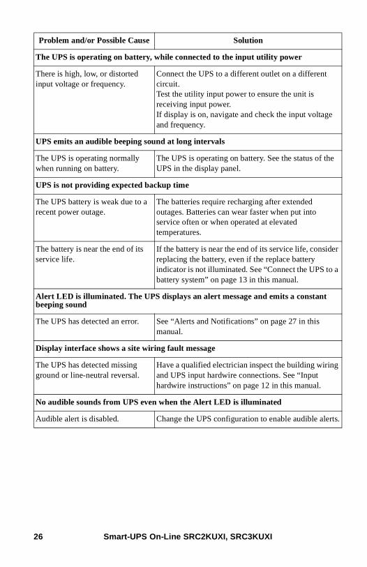
The UPS is operating on battery, while connected to the input utility power
There is high, low, or distorted input voltage or frequency.
Connect the UPS to a different outlet on a different circuit.Test the utility input power to ensure the unit is receiving input power.If display is on, navigate and check the input voltage and frequency.
UPS emits an audible beeping sound at long intervals
The UPS is operating normally when running on battery.
The UPS is operating on battery. See the status of the UPS in the display panel.
UPS is not providing expected backup time
The UPS battery is weak due to a recent power outage.
The batteries require recharging after extended outages. Batteries can wear faster when put into service often or when operated at elevated temperatures.
The battery is near the end of its service life.
If the battery is near the end of its service life, consider replacing the battery, even if the replace battery indicator is not illuminated. See “Connect the UPS to a battery system” on page 13 in this manual.
Alert LED is illuminated. The UPS displays an alert message and emits a constant beeping sound
The UPS has detected an error. See “Alerts and Notifications” on page 27 in this manual.
Display interface shows a site wiring fault message
The UPS has detected missing ground or line-neutral reversal.
Have a qualified electrician inspect the building wiring and UPS input hardwire connections. See “Input hardwire instructions” on page 12 in this manual.
No audible sounds from UPS even when the Alert LED is illuminated
Audible alert is disabled. Change the UPS configuration to enable audible alerts.
Problem and/or Possible Cause Solution
Smart-UPS On-Line SRC2KUXI, SRC3KUXI26
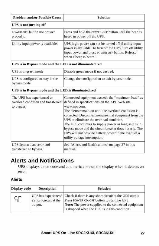
Alerts and NotificationsUPS displays a text code and a numeric code on the display when it detects an error.
Alerts
UPS is not turning off
POWER OFF button not pressed properly.
Press and hold the POWER OFF button until the beep is heard to power off the UPS.
Utility input power is available. UPS logic power can not be turned off if utility input power is available. To turn off the UPS, turn off utility input power and press POWER OFF button. Release when a beep is heard.
UPS is in Bypass mode and the LED is not illuminated red
UPS is in green mode Disable green mode if not desired.
UPS is configured to stay in the bypass mode.
Change the configuration to exit bypass mode.
UPS is in Bypass mode and the LED is illuminated red
The UPS has experienced an overload condition and transferred to bypass.
Connected equipment exceeds the “maximum load” as defined in specifications on the APC Web site, www.apc.com.The alerts remain on until the overload condition is corrected. Disconnect nonessential equipment from the UPS to eliminate the overload condition.The UPS continues to supply power as long as it is in bypass mode and the circuit breaker does not trip. The UPS will not provide battery power in the event of a utility voltage interruption.
UPS detected an error and transferred to bypass.
See “Alerts and Notifications” on page 27 in this manual.
Display code Description Solution
UPS has experienced a short circuit at the output.
Check if there is any short circuit at the UPS output.Press POWER ON/OFF button to start the UPS.Note: The power supplied to the connected equipment is dropped when the UPS is in this condition.
Problem and/or Possible Cause Solution
Smart-UPS On-Line SRC2KUXI, SRC3KUXI 27
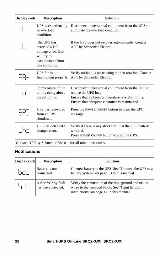
Notifications
UPS is experiencing an overload condition.
Disconnect nonessential equipment from the UPS to eliminate the overload condition.
The UPS has detected a DC voltage error. Unit will try to auto-recover from this condition.
If the UPS does not recover automatically, contact APC by Schneider Electric.
UPS fan is not functioning properly.
Verify nothing is obstructing the fan rotation. Contact APC by Schneider Electric.
Temperature of the unit is rising above the set limits.
Disconnect nonessential equipment from the UPS to reduce the UPS load.Ensure that ambient temperature is within limits.Ensure that adequate clearance is maintained.
UPS has recovered from an EPO shutdown.
Press the POWER ON/OFF button to clear the EPO message.
UPS has detected a charger error.
Verify if there is any short circuit at the UPS battery terminal.Press POWER ON/OFF button to start the UPS.
Contact APC by Schneider Electric for all other alert codes.
Display code Description Solution
Battery is not connected.
Connect battery to the UPS. See “Connect the UPS to a battery system” on page 13 in this manual.
A Site Wiring fault has been detected.
Verify the connection of the line, ground and neutral wires to the terminal block. See “Input hardwire instructions” on page 12 in this manual.
Display code Description Solution
Smart-UPS On-Line SRC2KUXI, SRC3KUXI28
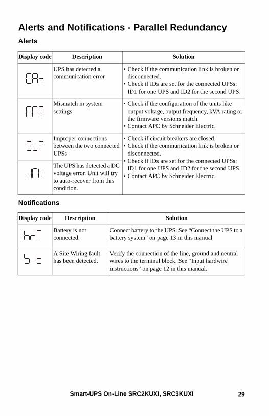
Alerts and Notifications - Parallel RedundancyAlerts
Notifications
Display code Description Solution
UPS has detected a communication error
• Check if the communication link is broken or disconnected.
• Check if IDs are set for the connected UPSs: ID1 for one UPS and ID2 for the second UPS.
Mismatch in system settings
• Check if the configuration of the units like output voltage, output frequency, kVA rating or the firmware versions match.
• Contact APC by Schneider Electric.
Improper connections between the two connected UPSs
• Check if circuit breakers are closed.• Check if the communication link is broken or
disconnected.• Check if IDs are set for the connected UPSs:
ID1 for one UPS and ID2 for the second UPS.• Contact APC by Schneider Electric.
The UPS has detected a DC voltage error. Unit will try to auto-recover from this condition.
Display code Description Solution
Battery is not connected.
Connect battery to the UPS. See “Connect the UPS to a battery system” on page 13 in this manual
A Site Wiring fault has been detected.
Verify the connection of the line, ground and neutral wires to the terminal block. See “Input hardwire instructions” on page 12 in this manual.
Smart-UPS On-Line SRC2KUXI, SRC3KUXI 29
ServiceIf the unit requires service, do not return it to the dealer. Follow these steps:
1. Review the Troubleshooting section of the manual to eliminate common problems.
2. If the problem persists, contact APC by Schneider Electric Customer Support.
a. Note the model number and serial number and the date of purchase. The model and serial numbers are located on the rear panel of the unit and are available through the LCD display on select models.
b. Call APC by Schneider Electric Customer Support and a technician will attempt to solve the problem over the phone. If this is not possible, the technician will issue a Service Request Number.
c. If the unit is under warranty, the repairs are free.
An Authorised Service Representative will visit your location and try to resolve the issue.
Limited Factory WarrantySchneider Electric IT Business India Private Ltd. (SEITBIPL), warrants its products to be free from defects in materials and workmanship for a period of two (2) years from the date of purchase. The SEITBIPL obligation under this warranty is limited to repairing or replacing, at its own sole option, any such defective products or parts there of. Repair or replacement of a defective product or part thereof does not extend the original warranty period.
This warranty applies only to the original purchaser who must have properly registered the product within 10 days of purchase. Products may be registered online at warranty.apc.com or by mailing in the completed warranty registration card that is included with the documentation.
SEITBIPL shall not be liable under the warranty if its testing and examination disclose that the alleged defect in the product does not exist or was caused by end user or any third person misuse, negligence, improper installation, testing, operation or use of the product contrary to SEITBIPL recommendations or specifications. Further, SEITBIPL shall not be liable for defects resulting from: 1) unauthorized attempts to repair or modify the product, 2) incorrect or inadequate electrical voltage or connection, 3) inappropriate on site operation conditions, 4) Acts of God, 5) exposure to the elements, 6) theft. In no event shall SEITBIPL have any liability under this warranty for any product where the serial number has been altered, defaced, or removed, 7) normal wear resulting from frequent use.
EXCEPT AS SET FORTH ABOVE, THERE ARE NO WARRANTIES, EXPRESS OR IMPLIED, BY OPERATION OF LAW OR OTHERWISE, APPLICABLE TO PRODUCTS SOLD, SERVICED OR FURNISHED UNDER THIS AGREEMENT OR IN CONNECTION HEREWITH.
SEITBIPL DISCLAIMS ALL IMPLIED WARRANTIES OF MERCHANTABILITY, SATISFACTION AND FITNESS FOR A PARTICULAR PURPOSE.
Smart-UPS On-Line SRC2KUXI, SRC3KUXI30

SEITBIPL EXPRESS WARRANTIES WILL NOT BE ENLARGED, DIMINISHED, OR AFFECTED BY AND NO OBLIGATION OR LIABILITY WILL ARISE OUT OF, SEITBIPL RENDERING OF TECHNICAL OR OTHER ADVICE OR SERVICE IN CONNECTION WITH THE PRODUCTS.
THE FOREGOING WARRANTIES AND REMEDIES ARE EXCLUSIVE AND IN LIEU OF ALL OTHER WARRANTIES AND REMEDIES. THE WARRANTIES SET FORTH ABOVE CONSTITUTE SEITBIPL’S SOLE LIABILITY AND PURCHASER’S EXCLUSIVE REMEDY FOR ANY BREACH OF SUCH WARRANTIES. SEITBIPL WARRANTIES EXTEND ONLY TO ORIGINAL PURCHASER AND ARE NOT EXTENDED TO ANY THIRD PARTIES.
IN NO EVENT SHALL SEITBIPL, ITS OFFICERS, DIRECTORS, AFFILIATES OR EMPLOYEES BE LIABLE FOR ANY FORM OF INDIRECT, SPECIAL, CONSEQUENTIAL OR PUNITIVE DAMAGES, ARISING OUT OF THE USE, SERVICE OR INSTALLATION OF THE PRODUCTS, WHETHER SUCH DAMAGES ARISE IN CONTRACT OR TORT, IRRESPECTIVE OF FAULT, NEGLIGENCE OR STRICT LIABILITY OR WHETHER SEITBIPL HAS BEEN ADVISED IN ADVANCE OF THE POSSIBILITY OF SUCH DAMAGES. SPECIFICALLY, SEITBIPL IS NOT LIABLE FOR ANY COSTS, SUCH AS LOST PROFITS OR REVENUE, WHETHER DIRECT OR INDIRECT, LOSS OF EQUIPMENT, LOSS OF USE OF EQUIPMENT, LOSS OF SOFTWARE, LOSS OF DATA, COSTS OF SUBSTITUANTS, CLAIMS BY THIRD PARTIES, OR OTHERWISE.
To obtain service under warranty you must call customer support. Customers with warranty claims issues may access the SEITBIPL worldwide customer support network through the SEITBIPL Web site: www.apc.com. Select your country from the country selection drop down menu. Open the Support tab at the top of the web page to obtain information for customer support in your region. Refer to the product user manual for more information on how to contact customer support.
APC by Schneider Electric Customer Support India
Internet http://www.apc.com/support
Toll Free 1 800 425 4272
E-mail [email protected]
Smart-UPS On-Line SRC2KUXI, SRC3KUXI 31

© 2014 APC by Schneider Electric. APC, the APC logo, and Smart-UPS are owned by Schneider Electric Industries S.A.S., or their affiliated companies. All other trademarks are property of their respective owners.
990-4510A9/2014