user interface design with matrix algebra - harold thimbleby · user interface design with matrix...
TRANSCRIPT
User interface design with matrix algebra
Harold Thimbleby
UCLIC, University College London Interaction Centre
It is usually very hard, both for designers and users, to reason reliably about user interfaces. Thispaper shows that ‘push button’ and ‘point and click’ user interfaces are algebraic structures. Userseffectively do algebra when they interact, and therefore we can be precise about some importantdesign issues and issues of usability. Matrix algebra, in particular, is useful for explicit calculationand for proof of various user interface properties.
With matrix algebra, we are able to undertake with ease unusally thorough reviews of real userinterfaces: this paper examines a mobile phone, a handheld calculator and a digital multimeteras case studies, and draws general conclusions about the approach and its relevance to design.
Categories and Subject Descriptors: B.8.2 [Performance and reliability]: Performance Analy-sis and Design Aids; D.2.2 [Software engineering]: Design Tools and Techniques—User Inter-faces; H.1.2 [Models and principles]: User/Machine Systems; H.5.2 [Information interfacesand presentation]: User interfaces (D.2.2, H.1.2, I.3.6)—Theory and methods
General Terms: Design, Human Factors, Performance
Additional Key Words and Phrases: Matrix algebra, Usability analysis, Feature interaction, Userinterface design
“It is no paradox to say that in our most theoretical moods we may be nearestto our most practical applications.” A. N. Whitehead
1. INTRODUCTION
User interface design is difficult, and in particular it is very hard to reason throughthe meanings of all the things a user can do, in all their many combinations. Typ-ically, real designs are not completely worked out and, as a result, very often userinterfaces have quirky features that interact in awkward ways. Detailed and precisecritiques of user interfaces are rare, and very little knowledge in design generalisesbeyond specific case studies. This paper addresses these problems by showing howmatrix algebra can be applied to user interface design. The paper explains thetheory in detail and shows it applied to three real case studies.
Address: UCLIC, University College London, Remax House, 31/32 Alfred Place, LONDON,WC1E 7DP, UK. URL: http://www.uclic.ucl.ac.uk
Permission to make digital or hard copies of part or all of this work for personal or classroom use isgranted without fee provided that copies are not made or distributed for profit or direct commercialadvantage and that copies show this notice on the first page or initial screen of a display alongwith the full citation. Copyrights for components of this work owned by others than ACM mustbe honored. Abstracting with credit is permitted. To copy otherwise, to republish, to post onservers, to redistribute to lists, or to use any component of this work in other works, requires priorspecific permission and/or a fee. Permissions may be requested from Publications Dept, ACMInc., 1515 Broadway, New York, NY 10036 USA, fax +1 (212) 869-0481, or [email protected].
2 · H. Thimbleby
1 Introduction 12 Contributions to HCI 3
2.1 Methodological issues . . . . . . . . . . . . . . . . . . . . . . . . . . . . . . . . . . . 42.2 The theory proposed . . . . . . . . . . . . . . . . . . . . . . . . . . . . . . . . . . . . 6
3 Introductory examples 73.1 A simple two button, two state system . . . . . . . . . . . . . . . . . . . . . . . . . . 73.2 Simple abstract matrix examples . . . . . . . . . . . . . . . . . . . . . . . . . . . . . 11
4 Example 1: The Nokia 5110 mobile phone 124.1 Inverses . . . . . . . . . . . . . . . . . . . . . . . . . . . . . . . . . . . . . . . . . . 144.2 Partial theorems . . . . . . . . . . . . . . . . . . . . . . . . . . . . . . . . . . . . . . 15
5 Projecting large state spaces onto smaller spaces 155.1 Matrix transforms . . . . . . . . . . . . . . . . . . . . . . . . . . . . . . . . . . . . . 16
6 Example 2: The Casio HL-820LC calculator 196.1 Solving user problems: Task/action mappings . . . . . . . . . . . . . . . . . . . . . . 246.2 Summary and comparisons with other designs . . . . . . . . . . . . . . . . . . . . . . 30
7 Example 3: The Fluke 185 digital multimeter 317.1 Specifying the Fluke 185 . . . . . . . . . . . . . . . . . . . . . . . . . . . . . . . . . 327.2 Qualifications . . . . . . . . . . . . . . . . . . . . . . . . . . . . . . . . . . . . . . . 357.3 Reordering states . . . . . . . . . . . . . . . . . . . . . . . . . . . . . . . . . . . . . 367.4 Remaining major features . . . . . . . . . . . . . . . . . . . . . . . . . . . . . . . . . 377.5 Soft buttons . . . . . . . . . . . . . . . . . . . . . . . . . . . . . . . . . . . . . . . . 38
8 Advanced issues and further work 398.1 Button modes . . . . . . . . . . . . . . . . . . . . . . . . . . . . . . . . . . . . . . . 398.2 Modes and partial theorems . . . . . . . . . . . . . . . . . . . . . . . . . . . . . . . . 428.3 Finding matrices from specifications . . . . . . . . . . . . . . . . . . . . . . . . . . . 438.4 Design tools . . . . . . . . . . . . . . . . . . . . . . . . . . . . . . . . . . . . . . . . 458.5 Constructive use of matrices . . . . . . . . . . . . . . . . . . . . . . . . . . . . . . . 468.6 Model checking and other approaches . . . . . . . . . . . . . . . . . . . . . . . . . . 468.7 Modes and the ordering states . . . . . . . . . . . . . . . . . . . . . . . . . . . . . . 478.8 Complexity theory . . . . . . . . . . . . . . . . . . . . . . . . . . . . . . . . . . . . . 478.9 Pseudo inverses . . . . . . . . . . . . . . . . . . . . . . . . . . . . . . . . . . . . . . 47
9 Conclusions 48A Simple matrix algebra 51
A.1 Partitions . . . . . . . . . . . . . . . . . . . . . . . . . . . . . . . . . . . . . . . . . 53A.2 Algebraic properties . . . . . . . . . . . . . . . . . . . . . . . . . . . . . . . . . . . . 54
B From finite state machines to matrix algebra 54B.1 Aren’t FSMs too restricted? . . . . . . . . . . . . . . . . . . . . . . . . . . . . . . . . 55
C Formal definitions and basic properties 57
User interface design with matrix algebra · 3
Push button devices are ubiquitous: mobile phones, many walk-up-and-use de-vices (such as ticket machines and chocolate vending machines), photocopiers, cam-eras, and so on are all examples. Many safety critical systems rely on push buttonuser interfaces, and they can be found in aircraft flight decks, medical care units,cars, and nuclear power stations, to name but a few. Large parts of desktop graph-ical interfaces are effectively push button devices: menus, buttons and dialog boxesall behave as simple push button devices, though buttons are pressed via a mouserather than directly by a finger. Touch screens turn displays into literal push but-ton devices, and are used, for example, in many public walk-up-and-use systems.The world wide web is the largest example by far of any push button interface.Interaction with all these systems can be represented using matrix algebra.
Matrices have three very important properties. Matrices are standard mathe-matical objects, with a history going back to the nineteenth century:1 this paperis not presenting and developing yet another notation and approach, but it showshow an established and well-defined technique can be applied fruitfully to serioususer interface design issues. Secondly, matrices are very easy to calculate with, sodesigners can work out user interface issues very easily, and practical design toolscan be built. Finally, matrix algebra has structure and properties: designers andHCI specialists can use matrix algebra to reason about what is possible and notpossible, and so on, in very general ways. This paper gives many examples.
There is a significant mathematical theory behind matrices, and it is drawing onthis established and standard theory that is one of the major advantages of theapproach.
Matrices are not necessarily device-based: there is no intrinsic ‘system’ or ‘cog-nitive’ bias. Matrix operations model actions that occur when user and systemsynchronise. Thus a button matrix represents as much the system responding to abutton push as the user pressing the button. Matrices can represent a system doingelectronics to make things happen, or they represent the user thinking about howthings happen. The algebra does not ‘look’ towards the system nor towards theuser. As used in this paper, it simply says what is possible given the definitions; itsays how humans and devices interact . . .
Readers who want a review of matrices should refer to Appendix A. There aremany textbooks available on matrix algebra (linear algebra); Broyden’s Basic Ma-trices [6] is one that emphasises partitions, a technique that is used extensively laterin this paper. Readers who want a formal background should refer to Appendix C.
2. CONTRIBUTIONS TO HCI
There are many theories in HCI that predict user performance. Fitt’s Law canbe used to estimate mouse movement times; Hick’s Law can be used to estimatedecision times. Recent theories extend and develop these basic ideas into systems,such as ACT/R [3], that are psychologically sophisticated models. When suitablyset up, these models can make predictions about user performance and behaviour.Models can either be used in design, on the assumption that the models producevalid results, or they can be used in research, to improve the validity of the assump-
1The Chinese solved equations using matrices as far back as 200bc, but the recognition of matricesas abstract mathematical structures came much later.
4 · H. Thimbleby
tions. ACT/R is only one of many approaches; it happens to be rather flexible andcomplex — many simpler approaches, both complementary and indeed rival havebeen suggested, including CCT [17], UAN [13], GOMS [7], PUM [36], IL [4] and soon (see [15] for a broad survey of evaluation tools). All these approaches have incommon that they are psychologically plausible, and to that extent they can be usedto calculate how users interact, for instance to estimate times to complete tasks orto calculate likely behaviour. Some HCI theories, such as information foraging [24],have a weaker base in psychology, but their aim, too, is to make predictions of userbehaviour. Of course, for the models to provide useful insights, they must not onlybe psychologically valid but also based on accurate and reasonable models of theinteractive system itself.
Unlike psychologically-based approaches, whose use requires considerable exper-tise, the only idea behind this paper is the application of standard mathematics.The ideas can be implemented by anyone, either by hand, writing programs or, mostconveniently, by using any of the widely available mathematical tools, such as Mat-lab, Axiom or Mathematica (see §8.3). Matrix algebra is well documented and caneasily be implemented in any interactive programming environment or prototypingsystem. User interfaces can be built out of matrix algebra straight forwardly, andthey can be run, for prototyping, production purposes or for evaluation purposes.
An important contribution this paper makes is that it shows how interaction withreal systems can be analysed and modelled rigorously, and theorems proved. Onemay uncover problems in a user interface design that other methods, particularlyones driven from psychological realism, would miss.
The method is simple. I emphasise that throughout this paper we see ‘inside’matrices. In many ways, the contents of a matrix and how one calculates with it cannormally be handed over to programs; the inside details are irrelvant to designers.For this paper, however, it is important to see that the approach works and that thecalculations are valid. A danger is that this paper gives a misleading impression ofcomplexity, whereas it is intended to give an accurate impression how the approachworks, and how from a mathematical point of view it is routine. Conversely, becausewe have presented relatively small examples, emphasising manageable expositiondespite the explicit calculations, there is an opposite danger that the approachseems only able to handle trivial examples!
2.1 Methodological issues
This paper makes a theoretical contribution to HCI. One might consider thatthere are two broad areas of theoretical contributions, which aspire, respectively,to psychological or computational validity. This paper makes computational con-tributions, and its validity does not depend on doing empirical experiments butrather on its theoretical foundations. The foundations are standard mathematicsand computer science, plus a theorem (see Appendix C). The theorem, once stated,seems very obvious but it appears to be a new insight, certainly for its applicationsto HCI and to user interface design.
The issue, then, for matrix algebra is not its psychological validity but whetherthe theoretical structure provides new insight into HCI. I claim it does, because itprovides an unusual and revealing degree of precision when handling real interactivedevices and their user interfaces.
User interface design with matrix algebra · 5
For example, one might do ordinary empirical studies of calculator use and seehow users perform. But, as I will show, there are some reasonable tasks that cannotbe achieved in any sensible way — and this result is provable.
It may be established empirically whether and to what extent such impossibletasks are an issue for users under certain circumstances, but for safety critical de-vices, say electronic diving aids for divers, or instrumentation in aircraft flight decks,the ability or inability to perform tasks is a safety issue, regardless of whether usersin empiricial experiments encounter the problems. Thus the theoretical frameworkraises empirical questions or raises risk issues, both of which can be addressed be-cause the theory provides a framework where the issues can be discovered, definedand explored.
This paper provides a whole variety of non-trivial design insights, both generalapproaches and related to specific interactive products: almost all of the resultsare new, and some are surprising. The real contribution, though, is the simple andgeneral method by which these results are obtained.
In proposing a new theory, we have the problem of showing its ability to scaleto interesting levels of complexity. The narrative of this paper necessarily coverssimple examples, but somehow I must imply bigger issues can be addressed. Myapproach has been to start with three real devices. Being real devices, any readerof this paper can go and check that I have understood them,2 represented themfaithfully in the theory, and obtained non-trivial insights. The three examples arevery different, and I have handled them in different ways to illustrate the flexibilityand generality of the approach. Also, I do everything with standard textbookmathematics; I have not introduced parameters or fudge factors; and I have notshied away from examining the real features and properties of the example systems.
A danger of this approach is that its accuracy relies on the accuracy of reverseengineering; the manufacturers of these devices did not provide their formal spec-ifications — I had to reconstruct them. Whilst this is a weakness, any reader cancheck my results against a real device, its user manual (if adequate), or by enter-ing into correspondence with the manufacturer. Of course, different manufacturersmake different products, and in a sense it is less interesting to have a faithful modelof a specific proprietary device than to have a model of a generic device of theright level of complexity: by reverse engineering, even allowing for errors, I havecertainly achieved the latter goal.
An alternative might have been to build one or more new systems, and exhibitthe theory used constructively. Here, there would be no doubt that the systemswere accurately specified — though the paper would have to devote some space toproviding the specifications of these new devices (which the reader cannot obtainas physical devices). But the worse danger would be that I might not have imple-mented certain awkward features at all: I would then be inaccurately claiming thetheory handled, say, ‘mobile phones’ when in fact it only handled the certain sortof mobile phone that I was able to implement. It would be very hard to tell thedifference between what I had done and what I should have done.
For this paper, I have also chosen relatively cheap handheld devices. Handhelddevices are typically used for specific tasks. Again, this makes both replication of
2Device definitions and other material is available at http://www.uclic.ucl.ac.uk/harold.
6 · H. Thimbleby
this work and its exposition easier. However, further work might wish to considersimilar sorts of user interface in cars — to radios, audio systems, navigation, airconditioning, security systems, cruise control and so on. Such user interfaces areubiquitous, and typically over-complex and under-specified. Computer-controlledinstruments contribute increasingly to driver satisfaction and comfort. The drivershave a primary task which is not using the interface (and from which they shouldnot be distracted), so user interface complexities are more of an issue. Cars arehigh-value items with long lifetimes, and remain on the market much longer thanhandheld devices. They are more similar, and used by many more people. Evensmall contributions to user interface design in this domain would have a significantimpact on safety and satisfaction for many people.
2.2 The theory proposed
The theory is that users do algebra, in particular (for the large class of systemsconsidered), linear algebra. Linear algebra happens to be very easy to calculatewith, so this is valuable for design and research. However, it is obviously contentiousto say that users do algebra! We are not claiming that when people interact withsystems that they engage in cognitive processes equivalent to certain specific sortsof calculation (such as matrix multiplication), but that they and the system theyinteract with obey the relevant laws of algebra. Indeed if users were involved inrequirements specification, they may have expressed views that are equivalent toalgebraic axioms.
Users do algebra in much the same way as a user putting an apple onto a pileof apples “adds one” even if they do not do any sums. Users of apple piles willbe familiar with all sorts of properties (e.g., putting an apple in, then removing anapple leaves the same quantity; or, you cannot remove more apples from a pile thanare in it; and so on) regardless of whether anyone does the calculations. Likewise,users will be (or could well be) familiar with the results of matrix algebra even ifthey do not do the calculations. Only a philosophical nominalist could disagree [5]with this position.
The brain is a symbolic, neural, molecular, quantum computer of some sort andthere is no evidence that users think about their actions in anything remotely likecalculating in a linear algebra. Yet we can still make tentative cognitive claims.There is no known easy way to invert a matrix. Therefore if a user interfaceeffectively involves reasoning about inverses, it is practically certain that users willfind it difficult to use reliably. Or: A user’s task can be expressed as a matrix;thus performing a task/action mapping (going from the task description to how itis to be achieved) is equivalent to factoring the matrix with the specific matricesavailable at the user interface. Factorisation is not easy however it is done (althoughthere are special cases) — we can conclude that whatever users do psychologically,if it is equivalent to factorisation, it will not be easy. Indeed, we know that userskeep track of very little in their heads [23], so users are like to find these operationsharder, not easier than the ‘raw’ algebra suggests.
What we do know about psychological processes suggests that the sort of alge-braic theory discussed in this paper is never going to predict preferences, motivation,pleasure, learning or probable errors — these are the concerns of psychological the-ories. On the other hand, we can say that some things will be impossible and some
User interface design with matrix algebra · 7
lightoff
lighton
PUSH
PUSH
lightoff
lighton
ON
OFF
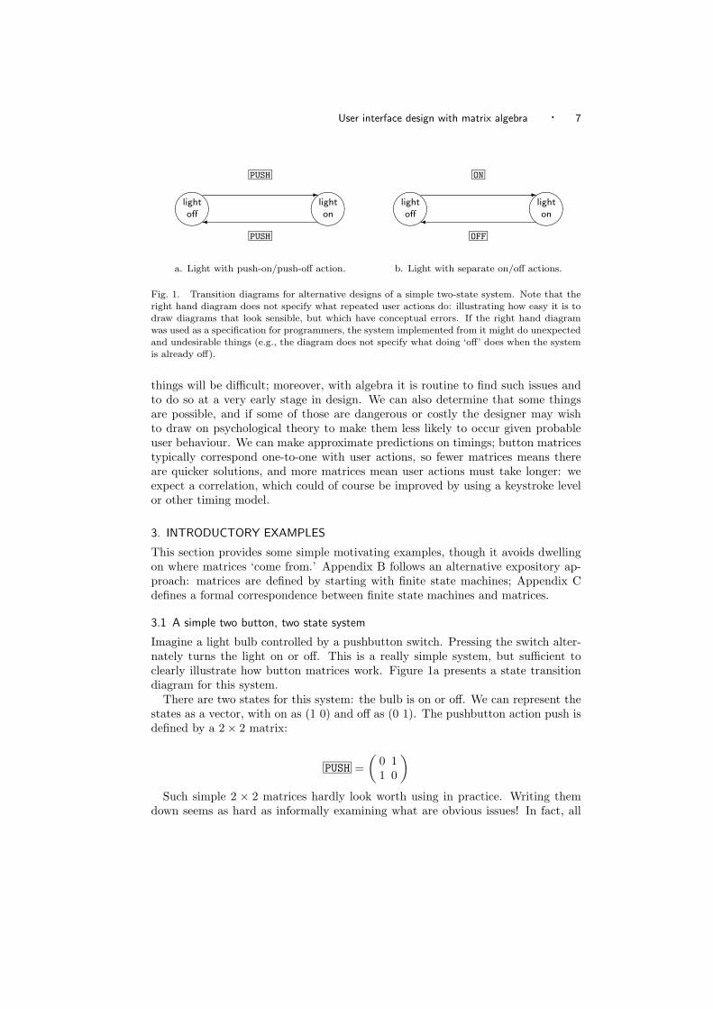
a. Light with push-on/push-off action. b. Light with separate on/off actions.
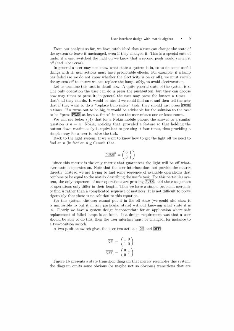
Fig. 1. Transition diagrams for alternative designs of a simple two-state system. Note that theright hand diagram does not specify what repeated user actions do: illustrating how easy it is todraw diagrams that look sensible, but which have conceptual errors. If the right hand diagramwas used as a specification for programmers, the system implemented from it might do unexpectedand undesirable things (e.g., the diagram does not specify what doing ‘off’ does when the systemis already off).
things will be difficult; moreover, with algebra it is routine to find such issues andto do so at a very early stage in design. We can also determine that some thingsare possible, and if some of those are dangerous or costly the designer may wishto draw on psychological theory to make them less likely to occur given probableuser behaviour. We can make approximate predictions on timings; button matricestypically correspond one-to-one with user actions, so fewer matrices means thereare quicker solutions, and more matrices mean user actions must take longer: weexpect a correlation, which could of course be improved by using a keystroke levelor other timing model.
3. INTRODUCTORY EXAMPLES
This section provides some simple motivating examples, though it avoids dwellingon where matrices ‘come from.’ Appendix B follows an alternative expository ap-proach: matrices are defined by starting with finite state machines; Appendix Cdefines a formal correspondence between finite state machines and matrices.
3.1 A simple two button, two state system
Imagine a light bulb controlled by a pushbutton switch. Pressing the switch alter-nately turns the light on or off. This is a really simple system, but sufficient toclearly illustrate how button matrices work. Figure 1a presents a state transitiondiagram for this system.
There are two states for this system: the bulb is on or off. We can represent thestates as a vector, with on as (1 0) and off as (0 1). The pushbutton action push isdefined by a 2 × 2 matrix:
PUSH =(
0 11 0
)Such simple 2 × 2 matrices hardly look worth using in practice. Writing them
down seems as hard as informally examining what are obvious issues! In fact, all
8 · H. Thimbleby
elementary introductions to matrices have the same problem.3 The point is thatthe matrix principles, while very obvious with such a simple system, also apply toarbitrarily complex systems, where thinking systematically about interaction wouldbe impractical. With a complex system, the matrix calculations would be done by aprogram or some other design or analysis tool: the designer or user would not needto see any details. For complex systems, the user interface properties are unlikelyto be obvious except by doing the matrix calculations. For large, complex systems,matrices promise rigour and clarity without overwhelming detail.
Doing the matrix multiplication we can check that if the light is off then pushingthe button makes the light go on:
off PUSH = (0 1)(
0 11 0
)= (1 0)= on
Similarly, we can show that pushing the button when the light is on puts it off,since on PUSH = off .
It seems that pushing the button twice does nothing, as certainly when the lightis off, one push puts it on, and a second puts it off. We could also check thatpressing push when it is on puts it off, and pressing it again puts it on, so we areback where we started. Rather than do these detailed calculations, which in generalcould be very tedious as we would normally expect to have far more than just twostates, we can find out what a double press of push means in any state:
PUSH PUSH =(
0 11 0
) (0 11 0
)=
(1 00 1
)= I
Thus the matrix multiplication PUSH times PUSH is equal to the identity matrixI. We can write this in either of the following ways:
PUSH PUSH = I
PUSH2
= I
Anything multiplied by I is unchanged — a basic law of matrices. In otherwords, doing push then push does nothing. Thus we now know without doing anycalculations on each state, that PUSH PUSH leaves the system in the same state, forevery starting state.
3You might first learn how to do two variable simultaneous equations, but next learning how touse 2 × 2 matrices to solve them further requires learning matrix multiplication, inverses and soon, and the effort does not seem to be adequately rewarded, since you could more easily solve theequation without matrices! However if you ever came across four, five or more variable equations— which you rarely do in introductory work — the advantages become stark.
User interface design with matrix algebra · 9
From our analysis so far, we have established that a user can change the state ofthe system or leave it unchanged, even if they changed it. This is a special case ofundo: if a user switched the light on we know that a second push would switch itoff (and vice versa).
In general a user may not know what state a system is in, so to do some usefulthings with it, user actions must have predictable effects. For example, if a lamphas failed (so we do not know whether the electricity is on or off), we must switchthe system off to ensure we can replace the lamp safely, to avoid electrocution.
Let us examine this task in detail now. A quite general state of the system is s.The only operation the user can do is press the pushbutton, but they can choosehow may times to press it; in general the user may press the button n times —that’s all they can do. It would be nice if we could find an n and then tell the userthat if they want to do a “replace bulb safely” task, they should just press PUSHn times. If n turns out to be big, it would be advisable for the solution to the taskto be “press PUSH at least n times” in case the user misses one or loses count.
We will see below (§4) that for a Nokia mobile phone, the answer to a similarquestion is n = 4. Nokia, noticing that, provided a feature so that holding thebutton down continuously is equivalent to pressing it four times, thus providing asimpler way for a user to solve the task.
Back to the light system. If we want to know how to get the light off we need tofind an n (in fact an n ≥ 0) such that
PUSHn
=(
0 10 1
)since this matrix is the only matrix that guarantees the light will be off what-
ever state it operates on. Note that the user interface does not provide the matrixdirectly; instead we are trying to find some sequence of available operations thatcombine to be equal to the matrix describing the user’s task. For this particular sys-tem, the only sequences of user operations are pressing PUSH , and these sequencesof operations only differ in their length. Thus we have a simple problem, meremlyto find n rather than a complicated sequence of matrices. It is not difficult to proverigorously that there is no solution to this equation.
For this system, the user cannot put it in the off state (we could also show itis impossible to put it in any particular state) without knowing what state it isin. Clearly we have a system design inappropriate for an application where safereplacement of failed lamps is an issue. If a design requirement was that a usershould be able to do this, then the user interface must be changed, for instance toa two-position switch.
A two-position switch gives the user two actions: ON and OFF :
ON =(
1 01 0
)OFF =
(0 10 1
)Figure 1b presents a state transition diagram that merely resembles this system:
the diagram omits some obvious (or maybe not so obvious) transitions that are
10 · H. Thimbleby
defined in the two matrices. We can check that ON works as expected whateverstate the system is in:
off ON = (0 1)(
1 01 0
)= (1 0)= on
on ON = (1 0)(
1 01 0
)= (1 0)= on
This check involves as many matrix calculations as there are states. This simplesystem only has two states, so it isn’t onerous to study, but we really need techniquesthat are easy to use when there are even millions of states. In general, a betterapproach will be more abstract.
Here there are just two user actions (and in general there will be many feweractions than there are states): we have just ON and OFF . Let us consider the userdoing anything then ON . There are only two possibilities: the user’s action canfollow either an earlier ON or an earlier OFF :
ON ON =(
1 01 0
) (1 01 0
)=
(1 01 0
)= ON
OFF ON =(
0 10 1
) (1 01 0
)=
(1 01 0
)= ON
These are calculations purely on the matrices, not on the states. (Coincidentally,and somewhat misleadingly, for this simple system there happen to be as many useractions as there are states, and we ended up calling them with the same names tooconfound the confusion!) The point is that we are now using the algebra to dealwith things the user does — actions — and this is generally much easier to do thanto look at the states.
In the two cases above the result is equivalent to pressing a single ON . We coulddo the same calculations where the second action is OFF , and we would find thatif there are two actions and the second is OFF the effect is the same as a singleOFF . This system is closed, meaning that any combination of actions is equivalentto a single user action. Closure is an important user interface property (it may notbe relevant for some designs or tasks): it guarantees anything the user can do canalways be done by a single action.
User interface design with matrix algebra · 11
This system is not only closed, but furthermore any sequence of actions is equiv-alent to the last action the user does. Here is a sketch of the proof. Consider anarbitrarily sequence S of user actions A1A2 . . . An for this system. (S = A1A2 . . . An
is just a matrix multiplication.) We have calculated that the system is closed forany two operations: A1A2 must be equivalent to either ON or OFF , and in fact itwill be equal to A2. But this followed by A3 will be either ON or OFF , so thatfollowed by A4 will be too . . . it’s not hard to follow the argument through andconclude that S = An. Put in other words, after any sequence of user actions,the state of the system is fully determined by the last user action. Specifically ifthe last thing the user does is switch off, whatever happened earlier, the systemwill be off; and if the last thing the user does is switch on, whatever happenedearlier, the system will be on. We now have a system that makes solving the taskof switching off reliably when not knowing the state very easy. For the scenario wewere imagining, this design will be a much safer system.
None of this is particularly surprising, because we are very familiar with inter-active systems that behave like this. And the two designs we considered were verysimple systems. What, then, have we achieved? I showed that various systemdesigns have usability properties that can be expressed and explored in matrix al-gebra. I showed we can do explicit calculations, and that the calculations give uswhat we expect, although more rigorously. We can do algebraic reasoning, in a waythat does not need to know or depend on the number of states involved.
3.2 Simple abstract matrix examples
Having seen what matrices can do for small concrete systems, we now explore someusability properties of systems in general — where, because of their complexity, wetypically not know beforehand what to expect.
Matrix multiplication does not commute: if A and B are two matrices, the twoproducts AB and BA are generally different. This means that pressing button Athen B is generally different from pressing B then A. The last system was non-commutative, since for it ON OFF = OFF ON . This is not a deep insight, but it isa short step from this sort of reasoning to understanding undo and error recovery,as we shall see below.
In a direct manipulation interface, a user might click on this or click on that ineither order. It is important that the end result is the same in either case. Or in apushbutton user interface there might be an array of buttons, which the user shouldbe able to press in any order that they choose. Both cases are examples of systemswhere we do want the corresponding matrices to commute. We should thereforeeither check Click 1 Click 2 = Click 2 Click 1 by proof or direct calculation withmatrices, or we should design the interface to ensure the matrices have the rightform to commute. Just as allowing a user to do operations in any order makes theinterface easier to use [30], the analysis of user interface design in this case becomesmuch easier since commutativity permits mathematical simplifications.
Suppose we want a design where pressing the button OFF is a shortcut for thetwo presses STOP OFF , for instance as might be relevant to the operation of a DVDplayer. The DVD might have two basic modes: playing and stopped. If you stopthe DVD then switch it off, this is the same as just switching it off — where it isalso stopped. What can we deduce? Let S and O be the corresponding matrices;
12 · H. Thimbleby
in principle we could ask the DVD manufacturer for them. The simple calculationSO = O will check the claim, and it checks it under all possible circumstances —the matrices O and S contain all the information for all possible states. This simpleequation puts some constraints on what S and O may be. For instance, assuming Sis non-trivial, we conclude that O is not invertible. We prove this by contradiction.
Assume SO = O, and assume O is invertible. If so, there is a matrix O−1 whichis the inverse of O. Follow both sides by this inverse: SOO−1 = OO−1 which canbe simplified to SI = I, as OO−1 = I. Since SI = S we conclude that S = I.Hence S is the identity matrix, and STOP does nothing. This is a contradiction,and we conclude that if O is a short cut then it cannot be invertible. If it is notinvertible, then in general a user will not be able to undo the effect of OFF .
What not being invertible means, more precisely, is that the user cannot returnto a previous state only knowing what they have just done. They also need to knowwhat state the device was in before the operation and be able to solve the problemof pressing the right buttons to reach that state.4
To summarise, if we had the three seemingly innocuous design requirements:
(1) STOP does something (such as switching the DVD off!)(2) OFF is a shortcut for STOP OFF
(3) OFF is undoable or invertible (e.g., so ON , would get the DVD back to whatevermode it was in before switching off — that is, where ON = OFF
−1)
then we have just proved that they are inconsistent: if we insist on them, weend up building a DVD player that must have bugs and must have a user manualthat is misleading too. Better, to avoid inconsistency, the designer must forego oneor more of the requirements (here, the second requirement is obviously too strict),or the designer can relax the requirements from being universal (fully true over allstates) to partial requirements (required only in certain states). I discuss partialtheorems below, in §4.2.
We now turn from these illustrative examples to some real case studies.
4. EXAMPLE 1: THE NOKIA 5110 MOBILE PHONE
The menu system of the Nokia 5110 mobile phone can be represented as a FSM of188 states, with buttons ∧ , ∨ , C , and NAVI (the Nokia context sensitive button:the meaning is changed according to the small screen display). In this paper I usea definition of the Nokia 5110, as published in full elsewhere [29].
First, we describe the user interface informally in English. The menu structure isentered by pressing NAVI and then using ∧ and ∨ to move up and down the menu.Items in the menu can be selected by pressing NAVI , and this will either access aphone function or select a submenu. The submenu, in turn, can be navigated upand down using ∧ and ∨ , and items within it selected by NAVI . The C key isused for correction, and ‘goes up a level’ to whatever menu item was selected beforethe last NAVI press. If the last press of NAVI selected a phone function, then Ccannot correct it — once a function is selected, the phone does the function and
4Or the user needs to know an algorithm to find an undo: for instance, to be able to recognise theprevious state, and be able to enumerate every state, would be sufficient — but hardly reasonableexcept on trivial devices.
User interface design with matrix algebra · 13
then reverts to the last menu position. The phone starts in a standby state, and inthis state C does nothing.
We may hope or expect the Nokia’s user interface to have certain properties. Itmay have been designed with certain properties in mind. Perhaps Nokia used asystem development process that ensured the phone had the intended properties.Be all this as it may, I will now show that from a matrix definition of the Nokia wecan reliably deduce and check properties.
We represent the buttons and button presses by boxed icons like ∧ and C , andwe would normally represent the matrices they represent by mathematical nameslike U and C, which for the present model of the Nokia are in fact 188 × 188matrices. But the buttons and matrices correspond, and they are essentially thesame thing: we may as well call the mathematical objects by names which are thebutton symbols themselves. So although our calculations look like sequences ofbutton presses, they are matrix algebra.
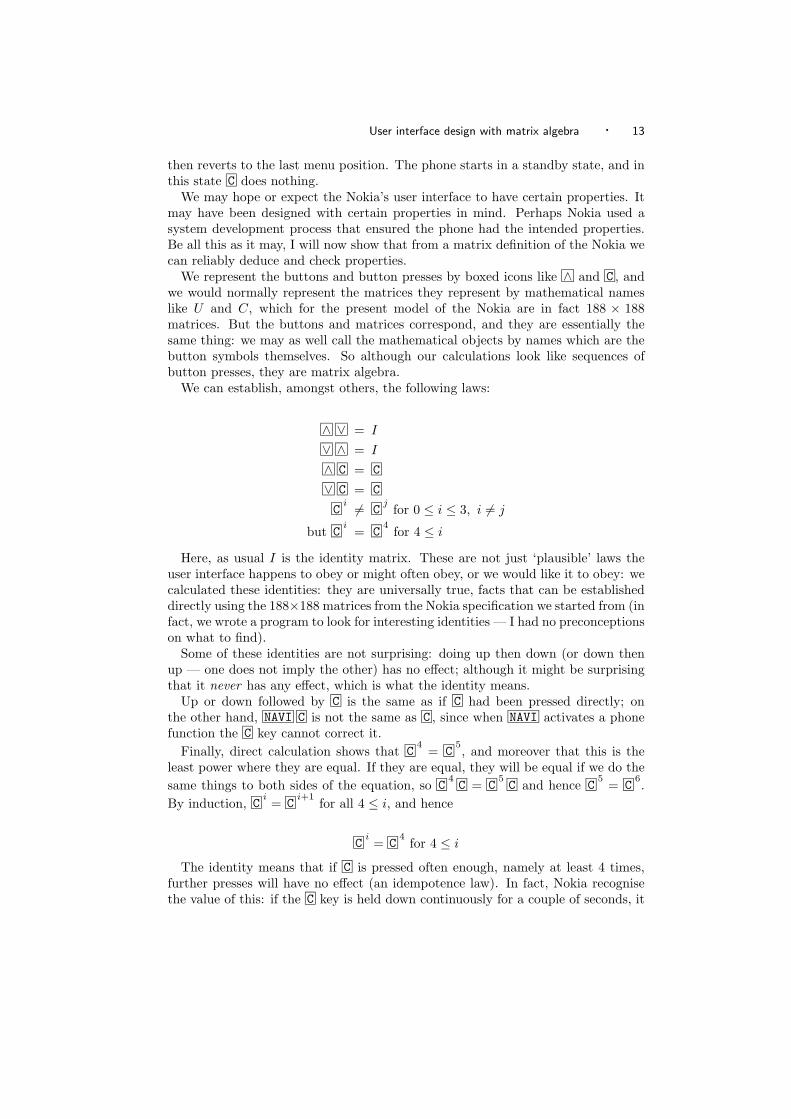
We can establish, amongst others, the following laws:
∧ ∨ = I
∨ ∧ = I
∧ C = C
∨ C = C
Ci = C
jfor 0 ≤ i ≤ 3, i = j
but Ci
= C4
for 4 ≤ i
Here, as usual I is the identity matrix. These are not just ‘plausible’ laws theuser interface happens to obey or might often obey, or we would like it to obey: wecalculated these identities: they are universally true, facts that can be establisheddirectly using the 188×188 matrices from the Nokia specification we started from (infact, we wrote a program to look for interesting identities — I had no preconceptionson what to find).
Some of these identities are not surprising: doing up then down (or down thenup — one does not imply the other) has no effect; although it might be surprisingthat it never has any effect, which is what the identity means.
Up or down followed by C is the same as if C had been pressed directly; onthe other hand, NAVI C is not the same as C , since when NAVI activates a phonefunction the C key cannot correct it.
Finally, direct calculation shows that C4
= C5, and moreover that this is the
least power where they are equal. If they are equal, they will be equal if we do thesame things to both sides of the equation, so C
4C = C
5C and hence C
5= C
6.
By induction, Ci= C
i+1for all 4 ≤ i, and hence
Ci= C
4for 4 ≤ i
The identity means that if C is pressed often enough, namely at least 4 times,further presses will have no effect (an idempotence law). In fact, Nokia recognisethe value of this: if the C key is held down continuously for a couple of seconds, it
14 · H. Thimbleby
behaves like C4
— thus the Nokia 5110 also has a user action ‘hold C’ with matrixdefined by
hold C = C4
4.1 Inverses
Matrices only have inverses if their determinants are non-zero. A property of de-terminants is that the determinant of a product is the product of the determinants:for any matrices A and B:
det(AB) = det(A) det(B)
In a product, if any factor is zero, the entire product is zero — zero times anythingis zero. So if any determinant is zero, the determinant of the entire product willbe zero. What this means for the user is that when they do a sequence of buttonpresses corresponding to the matrix product B1B2 . . . Bn, if any of them are notinvertible (not undoable), the entire sequence will not be invertible. So buttons withmatrices that have zero determinants (i.e., are singular) are potentially dangerous:if they are used in error, there is no uniform way to recover from the mistake. Theuser might have fortuitously kept a record of or memorised their actions up to thepoint where they made the mistake, and then they might be able to recover usingthe device’s buttons, but if so they are also having to use this additional knowledge,something external the device cannot help with.
If a matrix cannot be inverted (because it is singular) the user cannot undo theeffect of the corresponding button, but even if a matrix can be inverted in principle,in practice the user may not be able to undo its effect: they may not have access toall buttons that are factors of the inverse. The user is only provided with particularbuttons and hence can only construct particular matrices. A routine calculationcan establish what the user can do with their actual buttons; a designer may wishto check that every button’s inverse is a product of at least one other button. Forexample, the determinants of ∨ and ∧ on the Nokia mobile phone are both −1,which is non-zero, so these matrices can be inverted. The user might have brokenthe ∨ button. In this case, as ∧ is still invertible as a matrix, but the user cannotundo its effect (at least, without knowing a lot about the Nokia and the way ∧works in each menu level).
In contrast to ∨ and ∧ , the matrices C and NAVI are both singular, whichmeans they cannot be inverted. In other words, there is no matrix M such thatC M = I or NAVI M = I. Since there is no matrix, there is not even a sequence ofbutton presses that achieves this. But if there is no matrix, there is no such product— whatever the buttons. In user interface terms, this means that if C or NAVI arepressed by mistake, the user cannot in general recover from the error — at leastwithout knowing exactly what they were doing. If a matrix is not invertible, itmeans the device no longer knows what it was doing, and therefore it cannot goback in every case.
The strong, and in some contexts over-strict, proviso ‘in every case’ motivatesthe next section.
User interface design with matrix algebra · 15
4.2 Partial theorems
Theorems such as C4
= C5
can be found automatically, as can the fact that Cis not invertible. Theorems that are true, such as these, are not the only sort oftheorem that are relevant to usability.
A partial theorem is a theorem that is true for some states but not for all states.A user may be misled by a theorem that is, say, true in 90% of states. For example,they will use a device, and come to believe that ∧ ∨ = I, but one day they do ∧but find to their surprise that ∨ does not get them back — that is, in this scenariothe theorem ∧ ∨ = I is a partial theorem.
A designer must be interested in finding partial theorems. In particular, a de-signer will be interested in simple partial theorems — these are ones that a usercan easily infer and may believe to be universal; and a designer will be especiallyinterested in partial theorems that have safety or cost implications.
Once a partial theorem has been identified, it is then easy to find out details:
—The states in which the theorem fails can be determined. The designer canreconsider whether the device should be designed so that the theorem is true forthese states. Many partial theorems may fail when a device is off; this is a casethat is unlikely to raise a design issue.
—The button matrices that reveal the partiality can be determined. If a theoremis partial, it fails for some states only. The matrices that take the user to thosestates therefore correspond to the user actions that would reveal the failure of thetheorem. If these actions are guarded (e.g., by physical covers, locks, passwords)then the user will be less likely to take action to make the theorem fail. Forexample, we might decide to place a flap over the OFF button so it cannot bepressed by accident.
The discovery of theorems and partial theorems can be fully automated; we haveused Mathematica as well as our own design tool [12], which (unlike Mathemat-ica) hides the mathematics from designers. A brief comparison of our tool andMathematica can be found in [32].
We return to partial theorems in §8.2, after introducing more examples.
5. PROJECTING LARGE STATE SPACES ONTO SMALLER SPACES
Although it is possible to use matrices to model entire systems, often it is undesir-able to do so.
We may want to treat classes of states as equivalent. In a CD player, for instance,we may not really be interested in how much of which track is playing — we mightjust be interested in how playing works for any track. Or we may want to reasonclosely about a few buttons, and ignore the rest of the system. In fact we did thiswith the Nokia example in the last section: the Nokia mobile phone had a model of188 states, and while this completely described the menu subsystem of the Nokiaphone it did not cover any other features, such as dialling or SMS (short messageservice, for sending text messages). This was a pragmatic decision, and one thatcan be justified because other buttons on the phone (such as the digit keys) are‘obviously’ irrelevant to how the menu system works. But are they really?
We need a systematic and reliable approach to getting at the pertinent propertiesof systems we are interested in. In this paper, I discuss two approaches to this
16 · H. Thimbleby
problem: matrices themselves can be used (and this technique will be used later inthis paper), discussed below in §5.1, and computer algebra systems can transformfunctional specifications into matrices, discussed in §8.3.
5.1 Matrix transforms
This section shows how matrices can be used to reliably abstract out just thefeatures that are needed.
To project a large state vector to a smaller space, multiply by an appropriateprojection matrix. Simply, if the large state space has M states, the projectionmatrix P has M rows and N columns, then the projected state space vector sPwill have N columns (or equivalently, N states). We then consider button matricesoperating on sP rather than on s: these matrices will be square N × N matrices,possibly much smaller than the original M × M size. Suppose the fully explicitbutton matrices are B and the projected matrices are B′. All we require is sBP =sPB′ (i.e., that BP = PB′) to associate with any button matrix (or button matrixproduct) B the smaller projected matrix B′.
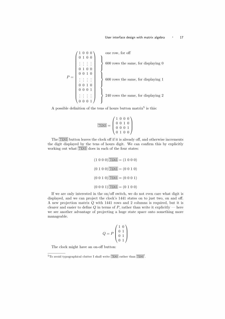
For concreteness consider a digital clock, and we will be interested in the be-haviour of the tens of hours setting button, TENS , and the on/off arrangements.Such clocks must display 24 hours and 60 minutes; they therefore need 24 × 60 =1440 states just to display the time. We also need an extra state for off, whenthe clock is in a state displaying no time at all. The state occupancy vector s istherefore a vector with 1441 elements, which is too big to write down explicitly.Our clock has four buttons to increment the corresponding digits, so that a usercan set the time. These buttons could be represented fully as 1441×1441 matrices.
We define a matrix P that projects the state space onto a smaller space, the spacewe are interested in exploring in detail. Suppose we want to work in the tens ofhours space, in which case P will project 1441 states to 4 states: off, or displaying0, 1, or 2 in the tens of hours column. Thus P will be a matrix with 4 columns and1441 rows.
There is not space here to show P explicitly because it has 5764 elements, andin any case that number of elements would be hard to interpret. The definition ofP depends on how states are arranged. We have to choose some convention for theprojected state space; for the sake of argument take
sP = ([off?] [displaying 0?] [displaying 1?] [displaying 2?])
where [e] means 0 or 1 depending on whether e is true — a convenient notation dueto Knuth [18]. If we assume the state vector s is arranged in the obvious way thatstate 1 is off, state 2 is displaying time 0000, state 3 is time 0001, state 4 is time0002 . . . state 60 is time 0059, state 61 is time 0100 . . . state 1441 is time 2359,then P will look like this:
User interface design with matrix algebra · 17
P =
1 0 0 00 1 0 0...
......
...0 1 0 00 0 1 0...
......
...0 0 1 00 0 0 1...
......
...0 0 0 1
one row, for off 600 rows the same, for displaying 0
600 rows the same, for displaying 1
240 rows the same, for displaying 2
A possible definition of the tens of hours button matrix5 is this:
TENS =
1 0 0 00 0 1 00 0 0 10 1 0 0
The TENS button leaves the clock off if it is already off, and otherwise increments
the digit displayed by the tens of hours digit. We can confirm this by explicitlyworking out what TENS does in each of the four states:
(1 0 0 0) TENS = (1 0 0 0)
(0 1 0 0) TENS = (0 0 1 0)
(0 0 1 0) TENS = (0 0 0 1)
(0 0 0 1) TENS = (0 1 0 0)
If we are only interested in the on/off switch, we do not even care what digit isdisplayed, and we can project the clock’s 1441 states on to just two, on and off.A new projection matrix Q with 1441 rows and 2 columns is required, but it isclearer and easier to define Q in terms of P , rather than write it explicitly — herewe see another advantage of projecting a huge state space onto something moremanageable.
Q = P
1 00 10 10 1
The clock might have an on-off button:
5To avoid typographical clutter I shall write TENS rather than TENS′.
18 · H. Thimbleby
ON-OFF =(
0 11 0
)The other buttons on this clock do not change the on/off state of the clock, so
in this state space they are identities, e.g.,
TENS =(
1 00 1
)Or perhaps the clock has two separate buttons, one for on, one for off?
ON =(
0 10 1
), OFF =
(1 01 0
)This looks pretty simple, but we can already use these matrices to make some user
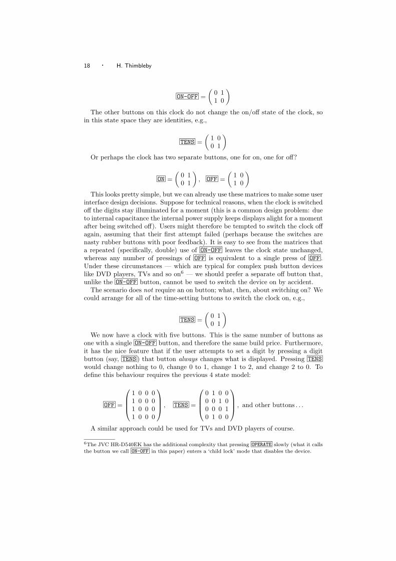
interface design decisions. Suppose for technical reasons, when the clock is switchedoff the digits stay illuminated for a moment (this is a common design problem: dueto internal capacitance the internal power supply keeps displays alight for a momentafter being switched off). Users might therefore be tempted to switch the clock offagain, assuming that their first attempt failed (perhaps because the switches arenasty rubber buttons with poor feedback). It is easy to see from the matrices thata repeated (specifically, double) use of ON-OFF leaves the clock state unchanged,whereas any number of pressings of OFF is equivalent to a single press of OFF .Under these circumstances — which are typical for complex push button deviceslike DVD players, TVs and so on6 — we should prefer a separate off button that,unlike the ON-OFF button, cannot be used to switch the device on by accident.
The scenario does not require an on button; what, then, about switching on? Wecould arrange for all of the time-setting buttons to switch the clock on, e.g.,
TENS =(
0 10 1
)We now have a clock with five buttons. This is the same number of buttons as
one with a single ON-OFF button, and therefore the same build price. Furthermore,it has the nice feature that if the user attempts to set a digit by pressing a digitbutton (say, TENS ) that button always changes what is displayed. Pressing TENSwould change nothing to 0, change 0 to 1, change 1 to 2, and change 2 to 0. Todefine this behaviour requires the previous 4 state model:
OFF =
1 0 0 01 0 0 01 0 0 01 0 0 0
, TENS =
0 1 0 00 0 1 00 0 0 10 1 0 0
, and other buttons . . .
A similar approach could be used for TVs and DVD players of course.
6The JVC HR-D540EK has the additional complexity that pressing OPERATE slowly (what it callsthe button we call ON-OFF in this paper) enters a ‘child lock’ mode that disables the device.
User interface design with matrix algebra · 19
6. EXAMPLE 2: THE CASIO HL-820LC CALCULATOR
Calculators differ in details of their design, and so to be specific I base our discussionon a particular calculator, the Casio HL-820LC, which is a market-leading andpopular handheld (5.5×10cm) calculator. It is a current model and can be readilyobtained: the discussion below should be easy to check if required. This sectioncloses with a brief comparison with some differently designed Casio calculators. Amore general critique of calculators (and a wider range of calculators) can be foundelsewhere [27].
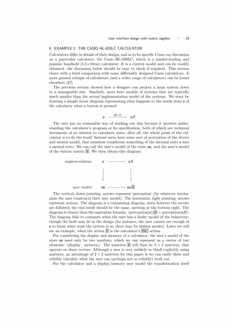
The previous section showed how a designer can project a large system downto a manageable size. Similarly, users have models of systems that are typicallymuch smaller than the actual implementation model of the systems. We start bydrawing a simple arrow diagram representing what happens to the inside state s ofthe calculator when a button is pressed:
s do B−−−−−−→ sB
The user has no reasonable way of working out this because it involves under-standing the calculator’s program or its specification, both of which are technicaldocuments of no interest to calculator users; after all, the whole point of the cal-culator is to do the work! Instead users have some sort of perception of the deviceand mental model, that somehow transforms something of the internal state s intoa mental state. We can call the user’s model of the state m, and the user’s modelof the button matrix B . We then obtain this diagram:
implementation: s −−−−−−→ sB
user model : m −−−−−−→ m B
The vertical, down pointing, arrows represent ‘perception’ (by whatever mecha-nism the user constructs their user model). The horizontal, right pointing, arrowsrepresent actions. The diagram is a commuting diagram, since however the arrowsare followed, the end result should be the same, meeting at the bottom right. Thediagram is clearer than the equivalent formula: (perception(s))B = perception(sB).The diagram fails to commute when the user has a faulty model of the behaviour,though the fault may lie in the design (for instance, the user cannot see enough ofs to know what state the system is in; there may be hidden modes). Later we willsee an example, when the action B is the calculator’s MRC action.
For considering the display and memory of a calculator, the user’s model of thestate m need only be two numbers, which we can represent as a vector of twoelements: (display memory). The matrices B will then be 2 × 2 matrices, thatoperate on these vectors. Although a user is very unlikely to think explicitly usingmatrices, an advantage of 2 × 2 matrices for this paper is we can easily show andreliably calculate what the user can (perhaps not so reliably) work out.
For the calculator and a display/memory user model the transformation itself
20 · H. Thimbleby
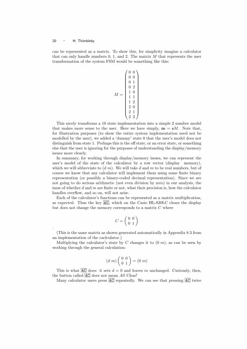
can be represented as a matrix. To show this, for simplicity imagine a calculatorthat can only handle numbers 0, 1, and 2. The matrix M that represents the usertransformation of the system FSM would be something like this:
M =
0 00 00 10 21 01 11 22 02 12 2
This nicely transforms a 10 state implementation into a simple 2 number model
that makes more sense to the user. Here we have simply, m = sM . Note that,for illustration purposes (to show the entire system implementation need not bemodelled by the user), we added a ‘dummy’ state 0 that the user’s model does notdistinguish from state 1. Perhaps this is the off state, or an error state, or somethingelse that the user is ignoring for the purposes of understanding the display/memoryissues more clearly.
In summary, for working through display/memory issues, we can represent theuser’s model of the state of the calculator by a row vector (display memory),which we will abbreviate to (d m). We will take d and m to be real numbers, but ofcourse we know that any calculator will implement them using some finite binaryrepresentation (or possibly a binary-coded decimal representation). Since we arenot going to do serious arithmetic (not even division by zero) in our analysis, theissue of whether d and m are finite or not, what their precision is, how the calculatorhandles overflow, and so on, will not arise.
Each of the calculator’s functions can be represented as a matrix multiplication,as expected. Thus the key AC , which on the Casio HL-820LC clears the displaybut does not change the memory corresponds to a matrix C where
C =(
0 00 1
).
(This is the same matrix as shown generated automatically in Appendix 8.3 froman implementation of the caclculator.)
Multiplying the calculator’s state by C changes it to (0 m), as can be seen byworking through the general calculation:
(d m)(
0 00 1
)= (0 m)
This is what AC does: it sets d = 0 and leaves m unchanged. Curiously, then,the button called AC does not mean All Clear!
Many calculator users press AC repeatedly. We can see that pressing AC twice
User interface design with matrix algebra · 21
has no further effect:
(d m)(
0 00 1
) (0 00 1
)= (0 m)
In fact, since (0 00 1
)2
=(
0 00 1
)we can prove that AC
n= AC for all n > 0; it is clear that pressing AC has no
effect beyond what can be achieved by pressing it just once (in technical terms, itis idempotent). Users who repeatedly press the AC button seem superstitious “wemust press it once, so pressing more times will be better” — or are not certain thatthe AC button works reliably. On the other hand, if users feel they need to pressAC multiple times to ensure it is definitely pressed, what does this say about theperceived reliability of other buttons needed for a calculation?
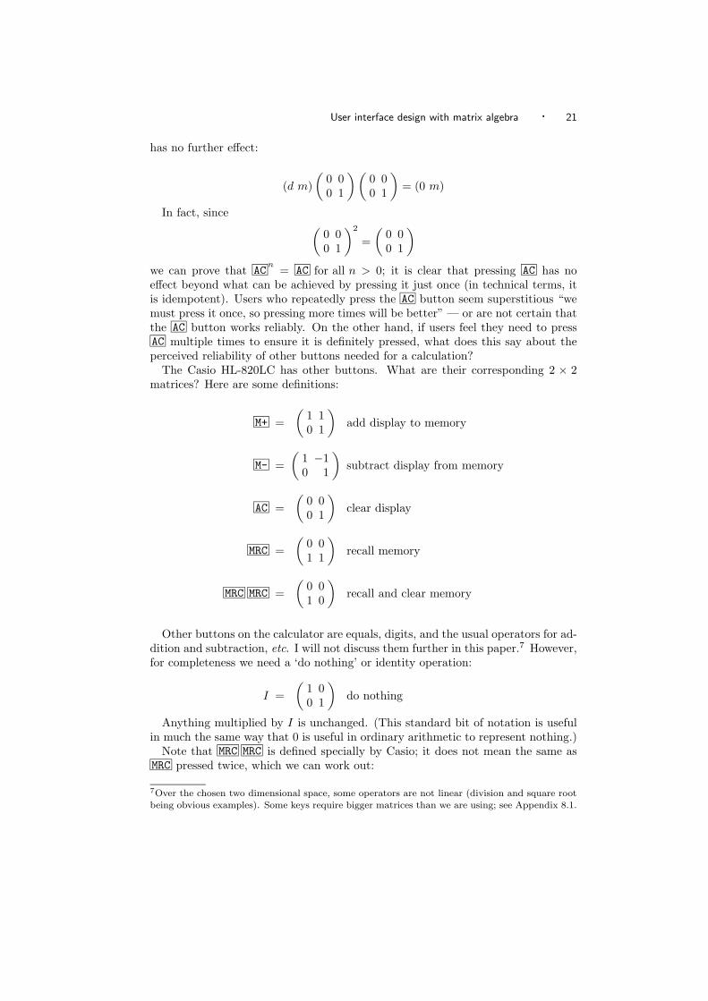
The Casio HL-820LC has other buttons. What are their corresponding 2 × 2matrices? Here are some definitions:
M+ =(
1 10 1
)add display to memory
M- =(
1 −10 1
)subtract display from memory
AC =(
0 00 1
)clear display
MRC =(
0 01 1
)recall memory
MRC MRC =(
0 01 0
)recall and clear memory
Other buttons on the calculator are equals, digits, and the usual operators for ad-dition and subtraction, etc. I will not discuss them further in this paper.7 However,for completeness we need a ‘do nothing’ or identity operation:
I =(
1 00 1
)do nothing
Anything multiplied by I is unchanged. (This standard bit of notation is usefulin much the same way that 0 is useful in ordinary arithmetic to represent nothing.)
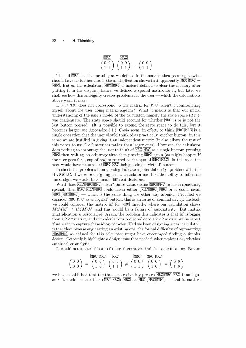
Note that MRC MRC is defined specially by Casio; it does not mean the same asMRC pressed twice, which we can work out:
7Over the chosen two dimensional space, some operators are not linear (division and square rootbeing obvious examples). Some keys require bigger matrices than we are using; see Appendix 8.1.
22 · H. Thimbleby
MRC MRC(0 01 1
) (0 01 1
)=
(0 01 1
)Thus, if MRC has the meaning as we defined in the matrix, then pressing it twice
should have no further effect: the multiplication shows that apparently MRC MRC =MRC . But on the calculator, MRC MRC is instead defined to clear the memory afterputting it in the display. Hence we defined a special matrix for it, but later weshall see how this ambiguity creates problems for the user — which the calculationsabove warn it may.
If MRC MRC does not correspond to the matrix for MRC , aren’t I contradictingmyself about the user doing matrix algebra? What it means is that our initialunderstanding of the user’s model of the calculator, namely the state space (d m),was inadequate. The state space should account for whether MRC is or is not thelast button pressed. (It is possible to extend the state space to do this, but itbecomes larger; see Appendix 8.1.) Casio seem, in effect, to think MRC MRC is asingle operation that the user should think of as practically another button: in thissense we are justified in giving it an independent matrix (it also allows the rest ofthis paper to use 2 × 2 matrices rather than larger ones). However, the calculatordoes nothing to encourage the user to think of MRC MRC as a single button: pressingMRC then waiting an arbitrary time then pressing MRC again (as might happen ifthe user goes for a cup of tea) is treated as the special MRC MRC . In this case, theuser would have no sense of MRC MRC being a single ‘virtual’ button.
In short, the problems I am glossing indicate a potential design problem with theHL-820LC: if we were designing a new calculator and had the ability to influencethe design, we would have made different decisions.
What does MRC MRC MRC mean? Since Casio define MRC MRC to mean somethingspecial, then MRC MRC MRC could mean either (MRC MRC ) MRC or it could meanMRC (MRC MRC ) — which is the same thing the other way around. Provided weconsider MRC MRC as a ‘logical’ button, this is an issue of commutativity. Instead,we could consider the matrix M for MRC directly, where our calculation showsM(MM) = (MM)M , and this would be a failure of associativity. But matrixmultiplication is associative! Again, the problem this indicates is that M is biggerthan a 2×2 matrix, and our calculations projected onto a 2×2 matrix are incorrectif we want to capture these idiosyncracies. Had we been designing a new calculator,rather than reverse engineering an existing one, the formal difficulty of representingMRC MRC as defined for this calculator might have encouraged finding a simplerdesign. Certainly it highlights a design issue that needs further exploration, whetherempirical or analytic.
It would not matter if both of these alternatives had the same meaning. But as
MRC MRC MRC MRC MRC MRC(0 00 0
)=
(0 01 0
) (0 01 1
)=
(0 01 1
) (0 01 0
)=
(0 01 0
)we have established that the three successive key presses MRC MRC MRC is ambigu-ous: it could mean either (MRC MRC ) MRC or MRC (MRC MRC ) — and it matters
User interface design with matrix algebra · 23
which! Thus the algebraic property of associativity is closely related to modeless-ness.8
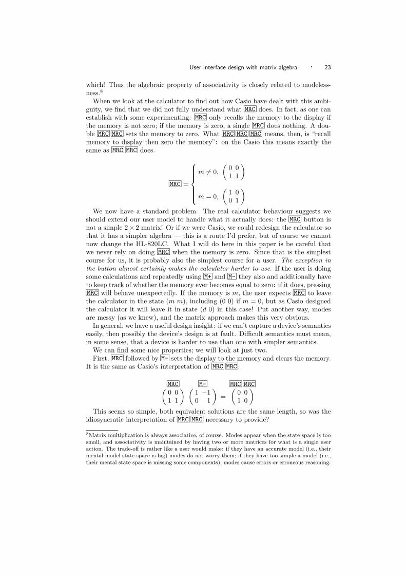
When we look at the calculator to find out how Casio have dealt with this ambi-guity, we find that we did not fully understand what MRC does. In fact, as one canestablish with some experimenting: MRC only recalls the memory to the display ifthe memory is not zero; if the memory is zero, a single MRC does nothing. A dou-ble MRC MRC sets the memory to zero. What MRC MRC MRC means, then, is “recallmemory to display then zero the memory”: on the Casio this means exactly thesame as MRC MRC does.
MRC =
m = 0,
(0 01 1
)
m = 0,
(1 00 1
)We now have a standard problem. The real calculator behaviour suggests we
should extend our user model to handle what it actually does: the MRC button isnot a simple 2× 2 matrix! Or if we were Casio, we could redesign the calculator sothat it has a simpler algebra — this is a route I’d prefer, but of course we cannotnow change the HL-820LC. What I will do here in this paper is be careful thatwe never rely on doing MRC when the memory is zero. Since that is the simplestcourse for us, it is probably also the simplest course for a user. The exception inthe button almost certainly makes the calculator harder to use. If the user is doingsome calculations and repeatedly using M+ and M- they also and additionally haveto keep track of whether the memory ever becomes equal to zero: if it does, pressingMRC will behave unexpectedly. If the memory is m, the user expects MRC to leavethe calculator in the state (m m), including (0 0) if m = 0, but as Casio designedthe calculator it will leave it in state (d 0) in this case! Put another way, modesare messy (as we knew), and the matrix approach makes this very obvious.
In general, we have a useful design insight: if we can’t capture a device’s semanticseasily, then possibly the device’s design is at fault. Difficult semantics must mean,in some sense, that a device is harder to use than one with simpler semantics.
We can find some nice properties; we will look at just two.First, MRC followed by M- sets the display to the memory and clears the memory.
It is the same as Casio’s interpretation of MRC MRC :
MRC M- MRC MRC(0 01 1
) (1 −10 1
)=
(0 01 0
)This seems so simple, both equivalent solutions are the same length, so was the
idiosyncratic interpretation of MRC MRC necessary to provide?
8Matrix multiplication is always associative, of course. Modes appear when the state space is toosmall, and associativity is maintained by having two or more matrices for what is a single useraction. The trade-off is rather like a user would make: if they have an accurate model (i.e., theirmental model state space is big) modes do not worry them; if they have too simple a model (i.e.,their mental state space is missing some components), modes cause errors or erroneous reasoning.
24 · H. Thimbleby
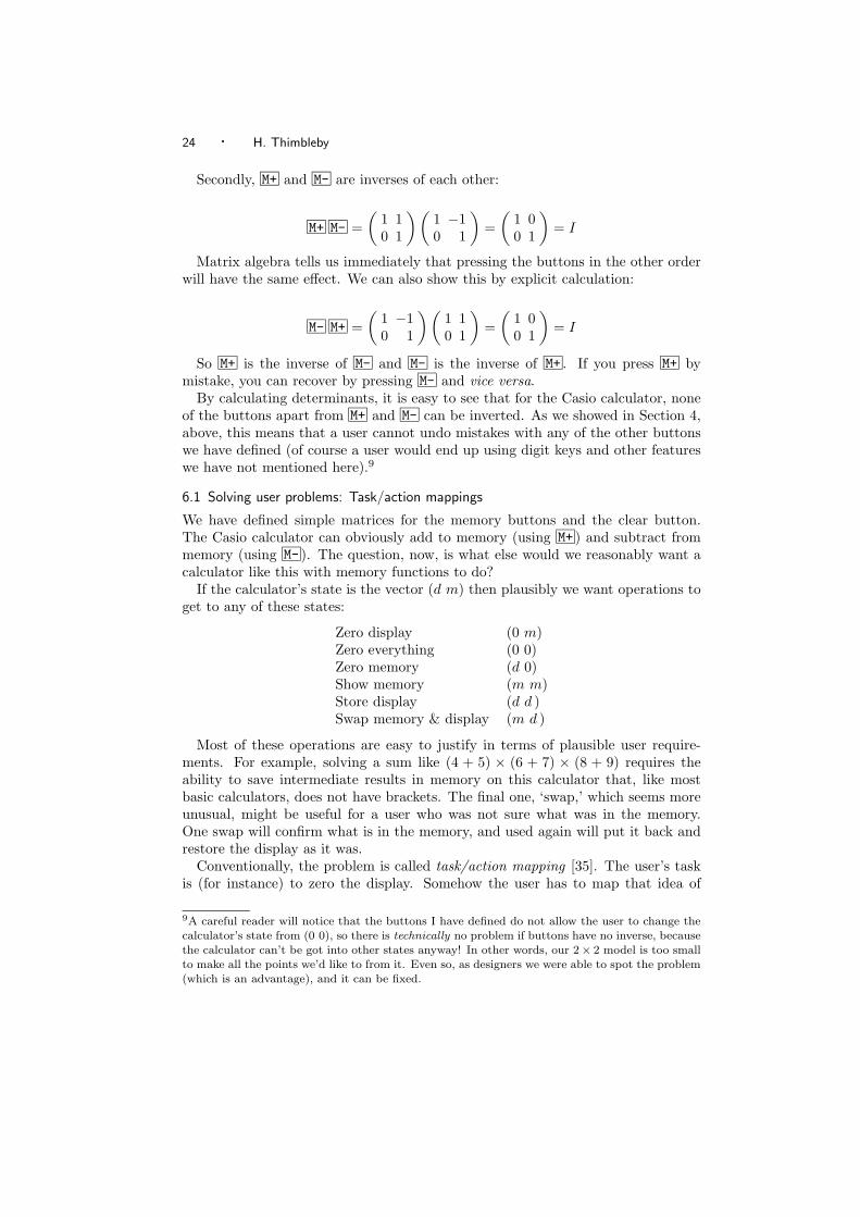
Secondly, M+ and M- are inverses of each other:
M+ M- =(
1 10 1
) (1 −10 1
)=
(1 00 1
)= I
Matrix algebra tells us immediately that pressing the buttons in the other orderwill have the same effect. We can also show this by explicit calculation:
M- M+ =(
1 −10 1
) (1 10 1
)=
(1 00 1
)= I
So M+ is the inverse of M- and M- is the inverse of M+ . If you press M+ bymistake, you can recover by pressing M- and vice versa.
By calculating determinants, it is easy to see that for the Casio calculator, noneof the buttons apart from M+ and M- can be inverted. As we showed in Section 4,above, this means that a user cannot undo mistakes with any of the other buttonswe have defined (of course a user would end up using digit keys and other featureswe have not mentioned here).9
6.1 Solving user problems: Task/action mappings
We have defined simple matrices for the memory buttons and the clear button.The Casio calculator can obviously add to memory (using M+ ) and subtract frommemory (using M- ). The question, now, is what else would we reasonably want acalculator like this with memory functions to do?
If the calculator’s state is the vector (d m) then plausibly we want operations toget to any of these states:
Zero display (0 m)Zero everything (0 0)Zero memory (d 0)Show memory (m m)Store display (d d )Swap memory & display (m d )
Most of these operations are easy to justify in terms of plausible user require-ments. For example, solving a sum like (4 + 5) × (6 + 7) × (8 + 9) requires theability to save intermediate results in memory on this calculator that, like mostbasic calculators, does not have brackets. The final one, ‘swap,’ which seems moreunusual, might be useful for a user who was not sure what was in the memory.One swap will confirm what is in the memory, and used again will put it back andrestore the display as it was.
Conventionally, the problem is called task/action mapping [35]. The user’s taskis (for instance) to zero the display. Somehow the user has to map that idea of
9A careful reader will notice that the buttons I have defined do not allow the user to change thecalculator’s state from (0 0), so there is technically no problem if buttons have no inverse, becausethe calculator can’t be got into other states anyway! In other words, our 2× 2 model is too smallto make all the points we’d like to from it. Even so, as designers we were able to spot the problem(which is an advantage), and it can be fixed.
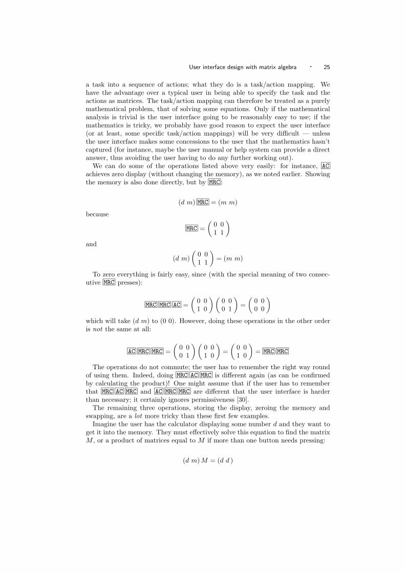
User interface design with matrix algebra · 25
a task into a sequence of actions; what they do is a task/action mapping. Wehave the advantage over a typical user in being able to specify the task and theactions as matrices. The task/action mapping can therefore be treated as a purelymathematical problem, that of solving some equations. Only if the mathematicalanalysis is trivial is the user interface going to be reasonably easy to use; if themathematics is tricky, we probably have good reason to expect the user interface(or at least, some specific task/action mappings) will be very difficult — unlessthe user interface makes some concessions to the user that the mathematics hasn’tcaptured (for instance, maybe the user manual or help system can provide a directanswer, thus avoiding the user having to do any further working out).
We can do some of the operations listed above very easily: for instance, ACachieves zero display (without changing the memory), as we noted earlier. Showingthe memory is also done directly, but by MRC :
(d m) MRC = (m m)
because
MRC =(
0 01 1
)and
(d m)(
0 01 1
)= (m m)
To zero everything is fairly easy, since (with the special meaning of two consec-utive MRC presses):
MRC MRC AC =(
0 01 0
) (0 00 1
)=
(0 00 0
)which will take (d m) to (0 0). However, doing these operations in the other orderis not the same at all:
AC MRC MRC =(
0 00 1
) (0 01 0
)=
(0 01 0
)= MRC MRC
The operations do not commute; the user has to remember the right way roundof using them. Indeed, doing MRC AC MRC is different again (as can be confirmedby calculating the product)! One might assume that if the user has to rememberthat MRC AC MRC and AC MRC MRC are different that the user interface is harderthan necessary; it certainly ignores permissiveness [30].
The remaining three operations, storing the display, zeroing the memory andswapping, are a lot more tricky than these first few examples.
Imagine the user has the calculator displaying some number d and they want toget it into the memory. They must effectively solve this equation to find the matrixM , or a product of matrices equal to M if more than one button needs pressing:
(d m) M = (d d )
26 · H. Thimbleby
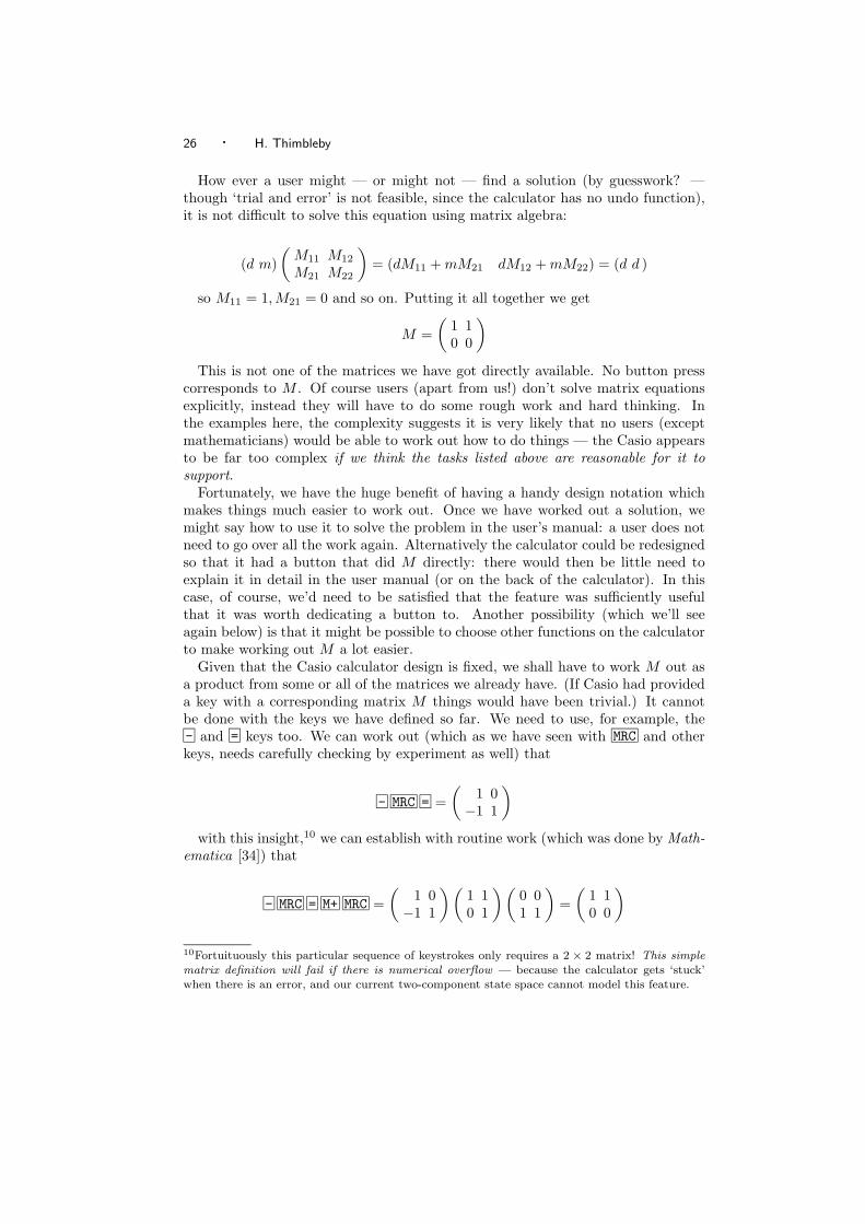
How ever a user might — or might not — find a solution (by guesswork? —though ‘trial and error’ is not feasible, since the calculator has no undo function),it is not difficult to solve this equation using matrix algebra:
(d m)(
M11 M12
M21 M22
)= (dM11 + mM21 dM12 + mM22) = (d d )
so M11 = 1, M21 = 0 and so on. Putting it all together we get
M =(
1 10 0
)This is not one of the matrices we have got directly available. No button press
corresponds to M . Of course users (apart from us!) don’t solve matrix equationsexplicitly, instead they will have to do some rough work and hard thinking. Inthe examples here, the complexity suggests it is very likely that no users (exceptmathematicians) would be able to work out how to do things — the Casio appearsto be far too complex if we think the tasks listed above are reasonable for it tosupport.
Fortunately, we have the huge benefit of having a handy design notation whichmakes things much easier to work out. Once we have worked out a solution, wemight say how to use it to solve the problem in the user’s manual: a user does notneed to go over all the work again. Alternatively the calculator could be redesignedso that it had a button that did M directly: there would then be little need toexplain it in detail in the user manual (or on the back of the calculator). In thiscase, of course, we’d need to be satisfied that the feature was sufficiently usefulthat it was worth dedicating a button to. Another possibility (which we’ll seeagain below) is that it might be possible to choose other functions on the calculatorto make working out M a lot easier.
Given that the Casio calculator design is fixed, we shall have to work M out asa product from some or all of the matrices we already have. (If Casio had provideda key with a corresponding matrix M things would have been trivial.) It cannotbe done with the keys we have defined so far. We need to use, for example, the- and = keys too. We can work out (which as we have seen with MRC and otherkeys, needs carefully checking by experiment as well) that
- MRC = =(
1 0−1 1
)with this insight,10 we can establish with routine work (which was done by Math-
ematica [34]) that
- MRC = M+ MRC =(
1 0−1 1
) (1 10 1
) (0 01 1
)=
(1 10 0
)10Fortuituously this particular sequence of keystrokes only requires a 2 × 2 matrix! This simplematrix definition will fail if there is numerical overflow — because the calculator gets ‘stuck’when there is an error, and our current two-component state space cannot model this feature.
User interface design with matrix algebra · 27
as required.11 If it’s so difficult — both to work out and to do — why would wewant to do it? Simple: the calculator has a memory and we might want to storea number we have worked out, currently in the display, into the memory. Surelythat is what the memory is for?
It seems clear that the calculator should have provided a STORE key to do thisoperation directly. It would then be very easy to store the display in memory. Notethat with the Casio design as it is, this sequence of operations includes matricesthat are not invertible: if the user makes a mistake, there is no way to recover(unless the user knows what the state previous was and how to reconstruct it).One needs to use a piece of paper to keep a record of the calculations — and ifyou’re using a piece of paper, what real use is the memory?
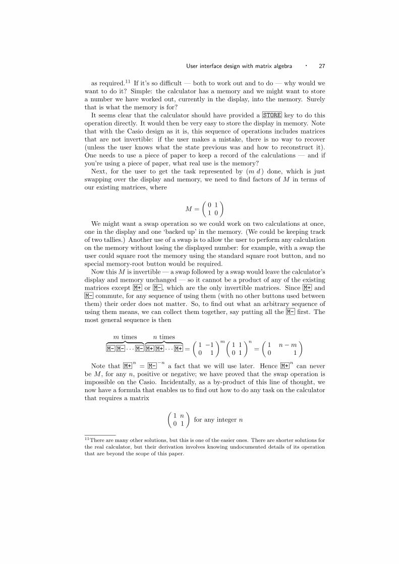
Next, for the user to get the task represented by (m d ) done, which is justswapping over the display and memory, we need to find factors of M in terms ofour existing matrices, where
M =(
0 11 0
)We might want a swap operation so we could work on two calculations at once,
one in the display and one ‘backed up’ in the memory. (We could be keeping trackof two tallies.) Another use of a swap is to allow the user to perform any calculationon the memory without losing the displayed number: for example, with a swap theuser could square root the memory using the standard square root button, and nospecial memory-root button would be required.
Now this M is invertible — a swap followed by a swap would leave the calculator’sdisplay and memory unchanged — so it cannot be a product of any of the existingmatrices except M+ or M- , which are the only invertible matrices. Since M+ andM- commute, for any sequence of using them (with no other buttons used betweenthem) their order does not matter. So, to find out what an arbitrary sequence ofusing them means, we can collect them together, say putting all the M- first. Themost general sequence is then
m times︷ ︸︸ ︷M- M- · · · M-
n times︷ ︸︸ ︷M+ M+ · · · M+ =
(1 −10 1
)m(1 10 1
)n
=(
1 n − m0 1
)Note that M+
n= M-
−na fact that we will use later. Hence M+
ncan never
be M , for any n, positive or negative; we have proved that the swap operation isimpossible on the Casio. Incidentally, as a by-product of this line of thought, wenow have a formula that enables us to find out how to do any task on the calculatorthat requires a matrix (
1 n0 1
)for any integer n
11There are many other solutions, but this is one of the easier ones. There are shorter solutions forthe real calculator, but their derivation involves knowing undocumented details of its operationthat are beyond the scope of this paper.
28 · H. Thimbleby
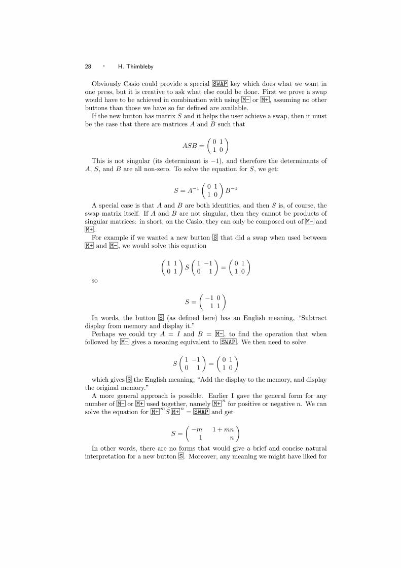
Obviously Casio could provide a special SWAP key which does what we want inone press, but it is creative to ask what else could be done. First we prove a swapwould have to be achieved in combination with using M- or M+ , assuming no otherbuttons than those we have so far defined are available.
If the new button has matrix S and it helps the user achieve a swap, then it mustbe the case that there are matrices A and B such that
ASB =(
0 11 0
)This is not singular (its determinant is −1), and therefore the determinants of
A, S, and B are all non-zero. To solve the equation for S, we get:
S = A−1
(0 11 0
)B−1
A special case is that A and B are both identities, and then S is, of course, theswap matrix itself. If A and B are not singular, then they cannot be products ofsingular matrices: in short, on the Casio, they can only be composed out of M- andM+ .
For example if we wanted a new button S that did a swap when used betweenM+ and M- , we would solve this equation(
1 10 1
)S
(1 −10 1
)=
(0 11 0
)so
S =(−1 0
1 1
)In words, the button S (as defined here) has an English meaning, “Subtract
display from memory and display it.”Perhaps we could try A = I and B = M- , to find the operation that when
followed by M- gives a meaning equivalent to SWAP . We then need to solve
S
(1 −10 1
)=
(0 11 0
)which gives S the English meaning, “Add the display to the memory, and display
the original memory.”A more general approach is possible. Earlier I gave the general form for any
number of M- or M+ used together, namely M+n
for positive or negative n. We cansolve the equation for M+
mS M+
n= SWAP and get
S =(−m 1 + mn
1 n
)In other words, there are no forms that would give a brief and concise natural
interpretation for a new button S . Moreover, any meaning we might have liked for
User interface design with matrix algebra · 29
S can be achieved using some combination of SWAP , M- and M+ : if we have SWAPwe do not need any of these esoteric buttons.
Overall, then, it would be better to have a SWAP button, or collect persuasiveempirical evidence that users do not want a swap operation! Since there are manycalculators on the market with the same style of design (i.e., memory buttons butno memory store button) and have been for several years, it would seem that usersfind the design sufficiently attractive. This might mean that the memory buttonsare there to sell calculators, or it might mean that users do not do sophisticatedthings with calculators, . . . leading us into speculation beyond the scope of thispaper.
Finally, consider the zero memory task. Here we need to find a matrix M suchthat
(d m)M = (d 0)
The Casio has no key that does this directly, so — as before — we will have tofind a sequence of button presses B1 B2 · · · Bn whose matrices multiply togetherto make M . If we had a STORE key, all this could have been achieved by doingSTORE MRC MRC : the STORE stores the display in memory, then the double-MRCrecovers memory and sets it to zero. We can check our reasoning:
STORE MRC MRC(1 10 0
) (0 01 0
)=
(1 00 0
)and
(d m)(
1 00 0
)= (d 0)
Although the Casio does not have a STORE button, we have already worked outa sequence that is equivalent to it, namely - MRC = M+ MRC . So to put zero in thememory, we should follow it by MRC MRC , which would mean this:
- MRC = M+ MRC MRC MRC
but this has got that problematic sequence of three consecutive MRC presses weexamined earlier. We discovered that the Casio would treat this as meaning thesame as
- MRC = M+ MRC MRC
Coincidentally this gives the required matrix, exactly what we wanted. There isno shorter solution.12
Earlier I claimed that the potential ambiguity of MRC MRC MRC could cause prob-lems. Yet here it looks like Casio’s design helps. Actually, we did not know Casio’sdesign decision would help — we had to work it out by doing the relevant matrixmultiplications. In other words, to find out how to perform a trivial and plausible-sounding task, we had to engage in formal reasoning that is beyond most users.This strongly suggests the calculator is badly designed in this respect.
12With the usual provisos. The device does have some undocumented tricks I have not exploited.
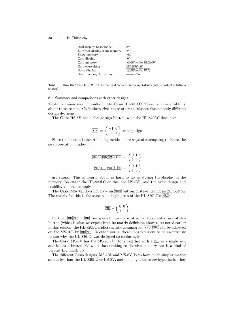
30 · H. Thimbleby
Add display to memory M+
Subtract display from memory M-
Show memory MRC
Zero display AC
Zero memory - MRC = M+ MRC MRC
Zero everything MRC MRC AC
Store display - MRC = M+ MRC
Swap memory & display impossible
Table 1. How the Casio HL-820LC can be used to do memory operations (with shortest solutionsshown).
6.2 Summary and comparisons with other designs
Table 1 summarises our results for the Casio HL-820LC. There is no inevitablilityabout these results: Casio themselves make other calculators that embody differentdesign decisions.
The Casio HS-8V has a change sign button, whic the HL-820LC does not:
+/- =(−1 0
0 1
)change sign
Since this button is invertible, it provides more ways of attempting to factor theswap operation. Indeed,
M+ - MRC M+ +/- =(
0 11 0
)M+ +/- MRC - = =
(0 11 0
)are swaps. This is clearly about as hard to do as storing the display in the
memory (on either the HL-820LC or this, the HS-8V), and the same design andusability comments apply.
The Casio MS-70L does not have an MRC button, instead having an MR button.The matrix for this is the same as a single press of the HL-820LC’s MRC :
MR =(
0 01 1
)Further, MR MR = MR : no special meaning is attached to repeated use of this
button (which is what we expect from its matrix definition above). As noted earlierin this section, the HL-820LC’s idiosyncratic meaning for MRC MRC can be achievedon the MS-70L by MR M- . In other words, there does not seem to be an intrinsicreason why the HL-820LC was designed so confusingly.
The Casio MS-8V has the MS-70L buttons together with a MC as a single key,and it has a button MU which has nothing to do with memory but is a kind ofpercent key, mark up.
The different Casio designs, MS-70L and MS-8V, both have much simpler matrixsemantics than the HL-820LC or HS-8V, and one might therefore hypothesise they
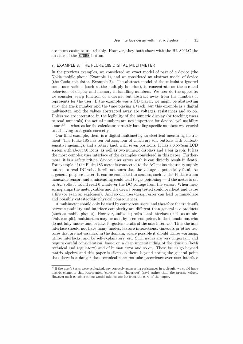
User interface design with matrix algebra · 31
are much easier to use reliably. However, they both share with the HL-820LC theabsence of the STORE button.
7. EXAMPLE 3: THE FLUKE 185 DIGITAL MULTIMETER
In the previous examples, we considered an exact model of part of a device (theNokia mobile phone, Example 1), and we considered an abstract model of device(the Casio calculator, Example 2). The abstract model of the calculator ignoredsome user actions (such as the multiply function), to concentrate on the use andbehaviour of display and memory in handling numbers. We now do the opposite:we consider every function of a device, but abstract away from the numbers itrepresents for the user. If the example was a CD player, we might be abstractingaway the track number and the time playing a track, but this example is a digitalmultimeter, and the values abstracted away are voltages, resistances and so on.Unless we are interested in the legibility of the numeric display (or teaching usersto read numerals) the actual numbers are not important for device-level usabilityissues13 — whereas for the calculator correctly handling specific numbers was crucialto achieving task goals correctly.
Our final example, then, is a digital multimeter, an electrical measuring instru-ment. The Fluke 185 has ten buttons, four of which are soft buttons with context-sensitive meanings, and a rotary knob with seven positions. It has a 6.5×5cm LCDscreen with about 50 icons, as well as two numeric displays and a bar graph. It hasthe most complex user interface of the examples considered in this paper. Further-more, it is a safety critical device: user errors with it can directly result in death.For example, if the Fluke 185 meter is connected to the AC mains electricity supplybut set to read DC volts, it will not warn that the voltage is potentially fatal. Asa general purpose meter, it can be connected to sensors, such as the Fluke carbonmonoxide sensor, and a misreading could lead to gas poisoning — if the meter is setto AC volts it would read 0 whatever the DC voltage from the sensor. When mea-suring amps the meter, cables and the device being tested could overheat and causea fire (or even an explosion). And so on; user/design error can lead to immediateand possibly catastrophic physical consequences.
A multimeter should only be used by competent users, and therefore the trade-offsbetween usability and interface complexity are different than general use products(such as mobile phones). However, unlike a professional interface (such as an air-craft cockpit), multimeters may be used by users competent in the domain but whodo not fully understand or have forgotten details of the user interface. Thus the userinterface should not have many modes, feature interactions, timeouts or other fea-tures that are not essential in the domain; where possible it should utilise warnings,utilise interlocks, and be self-explanatory, etc. Such issues are very important andrequire careful consideration, based on a deep understanding of the domain (bothtechnical and regulatory) and of human error and so on. These issues go beyondmatrix algebra and this paper is silent on them, beyond noting the general pointthat there is a danger that technical concerns take precedence over user interface
13If the user’s tasks were ecological, say correctly measuring resistances in a circuit, we could havematrix elements that represented ‘correct’ and ‘incorrect’ (say) rather than the precise values.However such considerations would take us too far from the core of the paper.
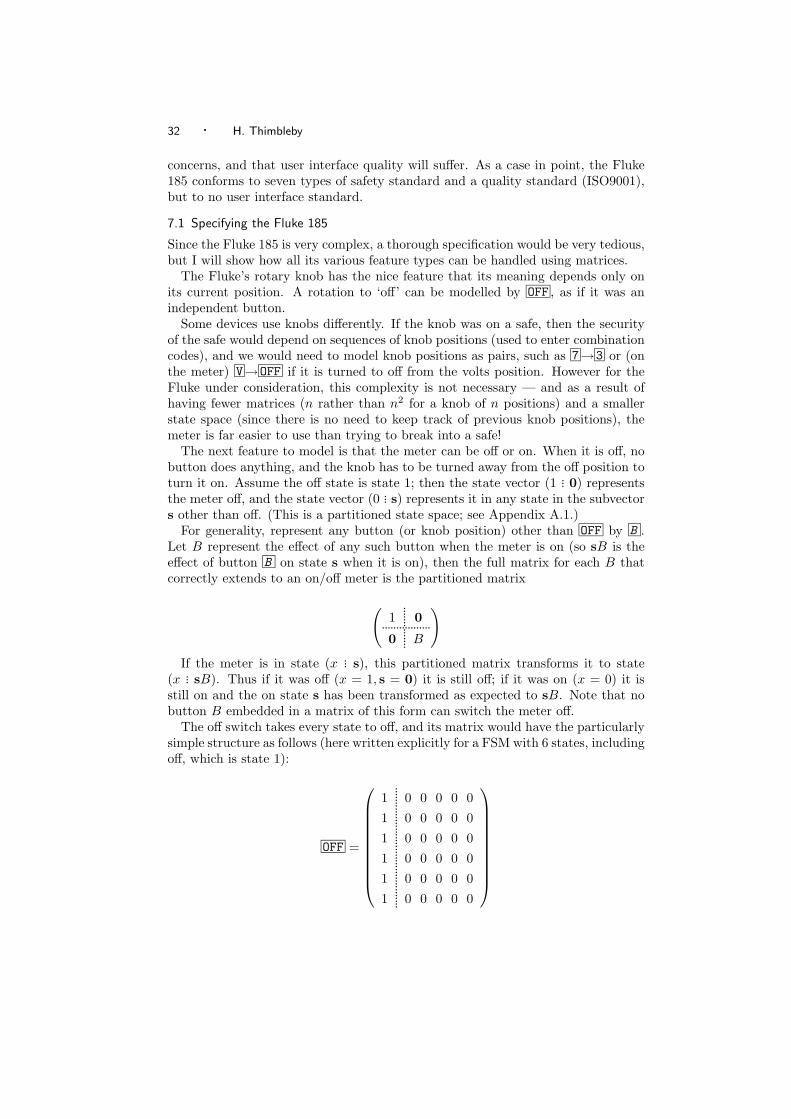
32 · H. Thimbleby
concerns, and that user interface quality will suffer. As a case in point, the Fluke185 conforms to seven types of safety standard and a quality standard (ISO9001),but to no user interface standard.
7.1 Specifying the Fluke 185
Since the Fluke 185 is very complex, a thorough specification would be very tedious,but I will show how all its various feature types can be handled using matrices.
The Fluke’s rotary knob has the nice feature that its meaning depends only onits current position. A rotation to ‘off’ can be modelled by OFF , as if it was anindependent button.
Some devices use knobs differently. If the knob was on a safe, then the securityof the safe would depend on sequences of knob positions (used to enter combinationcodes), and we would need to model knob positions as pairs, such as 7→3 or (onthe meter) V→OFF if it is turned to off from the volts position. However for theFluke under consideration, this complexity is not necessary — and as a result ofhaving fewer matrices (n rather than n2 for a knob of n positions) and a smallerstate space (since there is no need to keep track of previous knob positions), themeter is far easier to use than trying to break into a safe!
The next feature to model is that the meter can be off or on. When it is off, nobutton does anything, and the knob has to be turned away from the off position toturn it on. Assume the off state is state 1; then the state vector (1 ... 0) representsthe meter off, and the state vector (0 ... s) represents it in any state in the subvectors other than off. (This is a partitioned state space; see Appendix A.1.)
For generality, represent any button (or knob position) other than OFF by B .Let B represent the effect of any such button when the meter is on (so sB is theeffect of button B on state s when it is on), then the full matrix for each B thatcorrectly extends to an on/off meter is the partitioned matrix
(1
....... 0.................0
....... B
)If the meter is in state (x ... s), this partitioned matrix transforms it to state
(x ... sB). Thus if it was off (x = 1, s = 0) it is still off; if it was on (x = 0) it isstill on and the on state s has been transformed as expected to sB. Note that nobutton B embedded in a matrix of this form can switch the meter off.
The off switch takes every state to off, and its matrix would have the particularlysimple structure as follows (here written explicitly for a FSM with 6 states, includingoff, which is state 1):
OFF =
1....... 0 0 0 0 0
1....... 0 0 0 0 0
1....... 0 0 0 0 0
1....... 0 0 0 0 0
1....... 0 0 0 0 0
1....... 0 0 0 0 0
User interface design with matrix algebra · 33
This takes any state (x ... s) to (1 ... 0) as required. Repeating off does not achieveanything further; we can check by calculating OFF OFF = OFF , which is indeed thecase. Mechanically, because OFF is a knob position, it is impossible to repeat offwithout some other intermediate operation: thus it is fortunate it is idempotent andthe user would not be tempted to ‘really off’ the meter! (Compare this situationwith the AC key on the calculator.) In short, the knob’s physical affordance andits meaning correspond nicely [31].
In summary, once we have explored the meaning of OFF and the general behaviourof other buttons whether the meter is on or off, as above, we can ignore the off stateand concentrate our attention on the behaviour of the meter’s buttons when it ison. Partitioning is a powerful abstraction tool, and henceforth we can assume themeter is on.
The meter has a display light, which can be switched on or off. The behaviourof the meter is otherwise the same in either case. Introducing a two-state mode(light on, light off) therefore doubles the number of states. If the ‘light off’ statesare 1 . . . N , then the ‘light on’ states are (N +1) . . . 2N , a simple way of organisingthe state space is that switching the light on changes state from s to s + N , andswitching it off changes the state from s to s − N .
Now represent the state vector by (off ... on). The light switch can be representedby a partitioned matrix L that swaps the on and off states:
L =
(0
....... I...............I
....... 0
)The submatrices I and 0 here are of course all N × N matrices. This works as
required, as can be seen by multiplying out the effect of L on a general state vector
(x ... y)
(0
....... I...............I
....... 0
)= (y ... x)
For any other operation H (such as pressing, say, the HOLD button) we want itseffect in the light off states and the light on states to be the same. Again this isachieved using partitioned matrices, but in the following form:
(H
....... 0...................0
....... H
)Here, the submatrix H in the top left is applied to the light off states, and the
submatrix H in the lower right is applied to the light on states. For example,whatever state the meter is in with the light off, it goes to offH as required; andif the meter’s light is on, then off = 0 and offH = 0. From this matrix, it is clearthat H behaves as intended, identically in either set of states, and in particular itdoes not switch the light on or off. Thus matrices easily model the behaviour of allbuttons.
This recipe for handling any matrix H is independent of the light switch matrix.Thus we can consider the design of the meter ignoring the light, or we can consider
34 · H. Thimbleby
the light alone, or we can do both. As before, this freedom to abstract reliably isvery powerful. Indeed, if we were trying to reverse engineer the complete FSM forthe meter, building it up from the matrices in this way for each button would be apractical approach.
Given the partitioned structure of the meter’s button matrices, it is easy to showthat the light switch matrix L commutes with all matrices (except OFF , whichrequires L to be a submatrix of itself; see also §7.2), which means a user can starta measurement and then switch the light on, or first switch the light on — theresults will be the same. Other modes, such as measurement hold, can be treatedsimilarly.
At switch on, the meter allows 12 features to be tested, activated or adjusted. Forexample, switching on while pressing the soft F4 key causes the meter to display itsinternal battery voltage. (Because this is a switch-on feature, the soft key cannotbe labelled when the defice is off; a user would need to remember this feature.)As so far described, this is easy to model: the meter has one extra state for thisfeature, and it is reached only by the sequence OFF V F4 , where V F4 represents asimultaneous user action, turning the knob to volts while pressing F4 . Its matrixis routinely defined from submatrices. However, as the Fluke meter is defined, thelight button does not work in the new state: rather than switching on the light,it exits the new state and puts the meter into normal measuring mode (i.e., thestate corresponding to the normal meaning of whatever the knob is set to). Ifwe are to model this feature, the elegant ‘law’ about the light matrix and otherbutton matrices needs complicating: another idiosyncratic user interface feature ishard to model in matrix algebra. Although I do not have space to go into detailshere, this awkwardness with matrix representation seems to be an advantage:14
had Fluke used a matrix algebra approach, they would have been less likely tohave implemented this special feature. Indeed, the meter has a menu system (with8 functions) that can be accessed at any time: why wasn’t the battery voltagefeature put in the menu, so its user interface was handled uniformly?
The Fluke meter has a shift button, which changes the meaning of other buttonsif they are pressed immediately next. (It only changes the meaning of three buttons,including itself, all of which anyway have extra meanings if held down continuously;additionally, the shift button has a different, non-shift, meaning at switch on.) Ingeneral if S represents a shift button and A any button, we want SA to be thebutton matrix we choose to represent whatever “shifted A” means, and this shoulddepend only on A.
For any button A that is unaffected by the shift, of course we choose SA = A.Since the shift button doubles the number of states, we can define it in the usual wayas a partitioned matrix acting on a state vector (unshifted-state ... shifted-state).Since (at least on the Fluke) the shifted mode does not persist (it is not a lockableshift), all buttons now have partitioned matrices in the following simple form
14It requires a 3 × 3 partitioning, and no longer has the nice abstraction property; see §7.4 forother examples.
User interface design with matrix algebra · 35
(Aunshifted
....... 0...........................................0
....... Ashifted
)and
S =
(0
....... I...............I
....... 0
)which (correctly, for the Fluke) implies pressing SHIFT twice leaves the meter
unshifted (since the submatrices are all the same size and SS = I).For a full description of the meter, the various partition schemes have to be
combined. For example, we start with a matrix Rbasic to represent the RANGEbutton (the RANGE button basically operates over 6 or so range-related states, theexact number depending on the measurement), and we build up to a completematrix R which represents the RANGE button in all contexts. As it happens Rshifted is equal to R, and we can define the shift matrix:
Rs =
(Rbasic
....... 0..................................0
....... Rbasic
)Next we extend Rs to work with the light button. Again, R is the same whether
the light is on or off, so we require:
Rsl =
(Rs
....... 0.....................0
....... Rs
)Now Rsl defines the subset of the RANGE button’s meaning in the context of
the additional features activated by the shift key and the light keys. Note thatRsl = Rls (the meaning is independent of the order in which we construct it) asexpected — but see qualifications in §7.2. Next we extend Rsl so R works in thecontext of the meter being on or off:
R =
(1
....... 0...................0
....... Rsl
)This completes the construction of R with respect to the features of the meter
I have defined so far. Incidentally, this final matrix illustrates a case where thesubmatrices are not all square and not all the same size. If Rbasic is a 6× 6 matrix,this R is 25 × 25.
7.2 Qualifications
Sadly I idealised the Fluke 185, and the real meter has some complexities that wereglossed in the interests of brevity. The main qualifications are described in thissection.
36 · H. Thimbleby
I claimed that the construction of the R matrix to represent RANGE was indepen-dent of the order of applying shift and light constructions. Although this is trueas things are defined in this paper, it is not true for the Fluke 185, a fact whichI discovered as soon as I checked the claim! The light and shift buttons do notcommute on the Fluke: SHIFT LIGHT = LIGHT SHIFT . This quirk can only makethe Fluke harder to use (it also makes the user manual a little less accurate, and itwill have made the meter harder to program).15
In fact, the RANGE button has different effects under different measurement con-ditions, a different effect at power on, and it has a different effect in the menu andmemory subsystems, and another effect when it is held down for a few seconds. Therange feature also interacts with min/max; for example, it can get into states onlyin min/max mode where autoranging is disabled. For simplicity, I ignored thesedetails, which would be handled in the same way (but unfortunately not as cleanly)as the example features. Such feature interactions make the matrix partitions notimpossible, but too large to present in this paper.
Indeed, the Fluke 185 has many feature interactions. It seems plausible to con-clude that Fluke put together a number of useful features in the meter consideredindependently but did not explore the algebra of the integrated user interface. Theuser interface, when formalised, therefore reveals many ad hoc interactions betweenfeatures, all of which tend to make the user interface more complex and harder touse, and few or none of which have any technical justification.
The Fluke also has time dependencies. These can all be handled by introduc-ing a new matrix τ that is considered pressed every second, however the result ismathematically messy and not very illuminating. Had the designers specified theuser interface fully and correctly, they would naturally have wanted to avoid suchmessiness; furthermore, I can see no usability benefits of the timeouts in this con-text, to avoid the mathematical messiness would have improved the user interfacedesign.
The Fluke has a few further user interface features, such as soft buttons (themeaning of a soft button depends on what the display panel shows). These featuresprovide no difficulties for matrix algebra, and three following sections (§7.3, 7.4 and7.5) complete the example.
7.3 Reordering states
To handle the remaining features, we need to review a standard matrix technique;the benefit is further insight into tradeoffs in user interface design.
Section 7.1 made repeated use of partitioned matrices and made claims aboutthe relevance of the structure of matrices to the user interface. However it is notimmediately obvious that as partition structures are combined (e.g., for on/off andother features) that any relevant structures can be preserved, or even seen to bepreserved in the form taken by the matrix structures. This section briefly considersthis issue, and shows that it is trivial.
15If the meter’s software program is modularised, this ‘quirk’ requires wider interfaces or sharedglobal state, both of which are bad programming practice and tricky to get correct. If the meter’sprogram is not modular, then any ad hoc feature is more-or-less equally easy to program; but thisis not good practice: because there is then no specification of the program other than the ad hoccode itself.
User interface design with matrix algebra · 37
A user need not be concerned with state numbering, and in general will haveno idea what states are or are numbered as. From this perspective we can at anytime renumber states to obtain any matrix restructuring we please, provided onlythat we are methodical and keep track of the renumberings. Whilst this statementis correct, it is rather too informal for confidence. Also, an informal approach toswapping states misses out on an important advantage of using matrices to do thejob cleanly.
Any state renumbering can be represented as consistent row and column ex-changes in a transition matrix. For example, if rows 2 and 3 are swapped, andcolumns 2 and 3 swapped, then we obtain the equivalent matrix for a FSM butwith states 2 and 3 swapped. In general any renumbering is a permutation whichcan be represented by a matrix P . If M is a matrix, then PMPT is the corre-sponding matrix with rows and columns swapped according to the permutation P .If several permutations are required, they can either be done separately or com-bined, whichever is more convenient: e.g., as P1P2MPT
2 PT1 or as P3MPT
3 whereP3 = P1P2.
In short, throughout this paper, when any matrix M was presented, implicitlya permutation P was chosen to present it cleanly: we wrote down a neat M torepresent PMPT.
7.4 Remaining major features
Consider the Fluke 185 autohold feature. Often a user cannot both look at themeter and handle the probes. The Fluke 185 provides two features to help: a HOLDbutton freezes the display when it is pressed, and the AUTOHOLD feature (holdingdown the HOLD button for a couple of seconds) puts the meter into a mode whereit will automatically hold any stable non-zero measurement.
As so far described, modelling this requires a 2×2 partitioned matrix: the meterhas two sets of state, normal ones and autohold ones. The AUTOHOLD simply swapsbetween the two, in the same way as the light on/off button:
Abasic =
(0
....... I...............I
....... 0
)Pressing the button again gets the meter out of autohold mode, and because
both submatices are identities, returns the meter to the original state.In fact, autohold is not available in capacitance measurements.16 There is there-
fore one state where the autohold leaves the meter in the same state, namely thecapacitance state. Introduce a permutation P so that the capacitance state is thefirst state, as this allows us to write down the autohold matrix in a particularlysimple form:
16The meter may not implement autohold for capacitance possibly because the meter is unableto measure capacitance fast enough, and incomplete readings might be confused by the meter forstable readings. On the other hand, because capacitance measurements can be slow — they cantake minutes (because high value capacitors charged to high voltages have to be discharged safely)— users would appreciate the autohold’s automatic beeping when the measurement was ready.
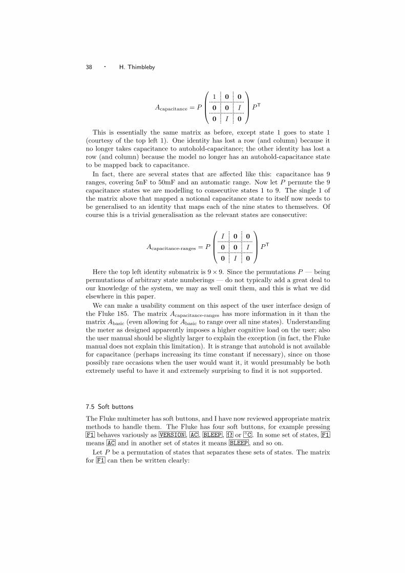
38 · H. Thimbleby
Acapacitance = P
1
....... 0....... 0........................
0....... 0
....... I........................0
....... I....... 0
PT
This is essentially the same matrix as before, except state 1 goes to state 1(courtesy of the top left 1). One identity has lost a row (and column) because itno longer takes capacitance to autohold-capacitance; the other identity has lost arow (and column) because the model no longer has an autohold-capacitance stateto be mapped back to capacitance.
In fact, there are several states that are affected like this: capacitance has 9ranges, covering 5nF to 50mF and an automatic range. Now let P permute the 9capacitance states we are modelling to consecutive states 1 to 9. The single 1 ofthe matrix above that mapped a notional capacitance state to itself now needs tobe generalised to an identity that maps each of the nine states to themselves. Ofcourse this is a trivial generalisation as the relevant states are consecutive:
Acapacitance-ranges = P
I
....... 0....... 0........................
0....... 0
....... I........................0
....... I....... 0
PT
Here the top left identity submatrix is 9× 9. Since the permutations P — beingpermutations of arbitrary state numberings — do not typically add a great deal toour knowledge of the system, we may as well omit them, and this is what we didelsewhere in this paper.
We can make a usability comment on this aspect of the user interface design ofthe Fluke 185. The matrix Acapacitance-ranges has more information in it than thematrix Abasic (even allowing for Abasic to range over all nine states). Understandingthe meter as designed apparently imposes a higher cognitive load on the user; alsothe user manual should be slightly larger to explain the exception (in fact, the Flukemanual does not explain this limitation). It is strange that autohold is not availablefor capacitance (perhaps increasing its time constant if necessary), since on thosepossibly rare occasions when the user would want it, it would presumably be bothextremely useful to have it and extremely surprising to find it is not supported.
7.5 Soft buttons
The Fluke multimeter has soft buttons, and I have now reviewed appropriate matrixmethods to handle them. The Fluke has four soft buttons, for example pressingF1 behaves variously as VERSION , AC , BLEEP , Ω or C . In some set of states, F1means AC and in another set of states it means BLEEP , and so on.
Let P be a permutation of states that separates these sets of states. The matrixfor F1 can then be written clearly:
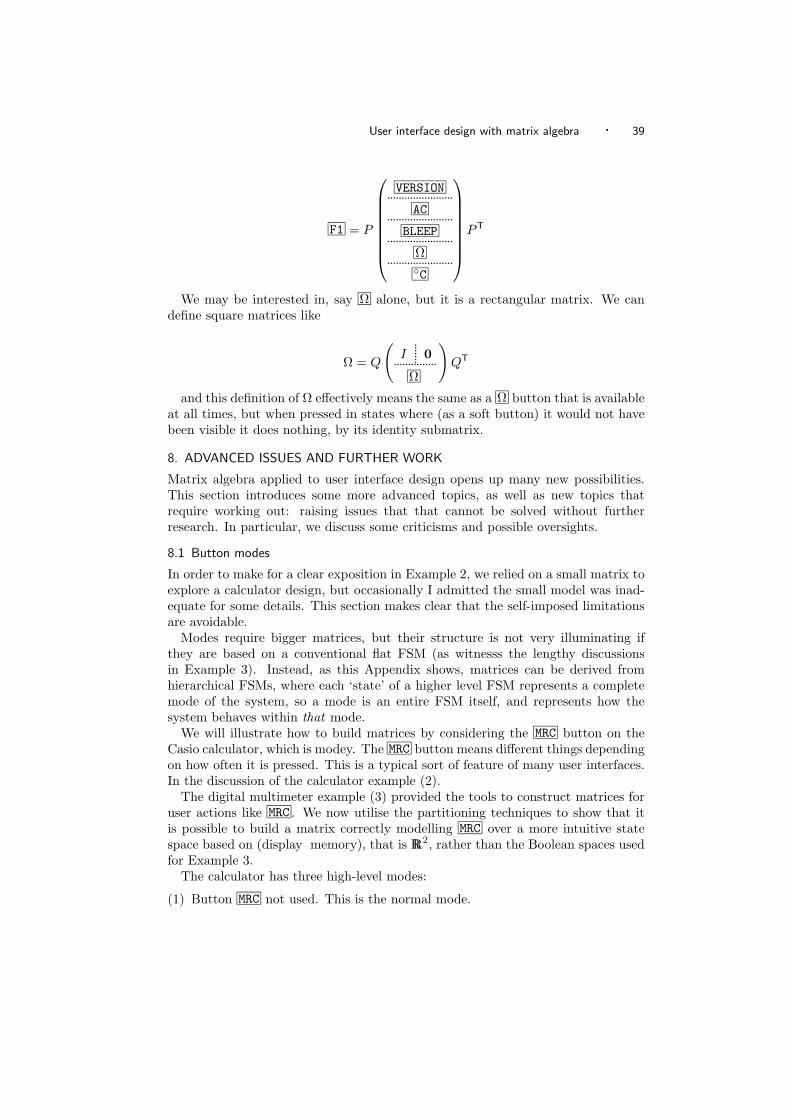
User interface design with matrix algebra · 39
F1 = P
VERSION.......................AC.......................
BLEEP.......................Ω.......................C
PT
We may be interested in, say Ω alone, but it is a rectangular matrix. We candefine square matrices like
Ω = Q
(I
....... 0...............Ω
)QT
and this definition of Ω effectively means the same as a Ω button that is availableat all times, but when pressed in states where (as a soft button) it would not havebeen visible it does nothing, by its identity submatrix.
8. ADVANCED ISSUES AND FURTHER WORK
Matrix algebra applied to user interface design opens up many new possibilities.This section introduces some more advanced topics, as well as new topics thatrequire working out: raising issues that that cannot be solved without furtherresearch. In particular, we discuss some criticisms and possible oversights.
8.1 Button modes
In order to make for a clear exposition in Example 2, we relied on a small matrix toexplore a calculator design, but occasionally I admitted the small model was inad-equate for some details. This section makes clear that the self-imposed limitationsare avoidable.
Modes require bigger matrices, but their structure is not very illuminating ifthey are based on a conventional flat FSM (as witnesss the lengthy discussionsin Example 3). Instead, as this Appendix shows, matrices can be derived fromhierarchical FSMs, where each ‘state’ of a higher level FSM represents a completemode of the system, so a mode is an entire FSM itself, and represents how thesystem behaves within that mode.
We will illustrate how to build matrices by considering the MRC button on theCasio calculator, which is modey. The MRC button means different things dependingon how often it is pressed. This is a typical sort of feature of many user interfaces.In the discussion of the calculator example (2).
The digital multimeter example (3) provided the tools to construct matrices foruser actions like MRC . We now utilise the partitioning techniques to show that itis possible to build a matrix correctly modelling MRC over a more intuitive statespace based on (display memory), that is RR2, rather than the Boolean spaces usedfor Example 3.
The calculator has three high-level modes:
(1) Button MRC not used. This is the normal mode.
40 · H. Thimbleby
(2) Button MRC pressed once. The memory is recalled to the display. Call thisbutton matrix M1.
(3) Button MRC pressed more than once. The memory is cleared. Since this modefollows Mode 2, the display will continue to show the previous memory contents.Call this button matrix M2.
The key MRC goes between the modes (specifically, 1 → 2 → 3 → 3 · · ·), andwhat we might call ANY (i.e., any action other than MRC ) returns to normal mode(· · · → 1), as well as doing whatever it does in that mode. For example, AC returnsto Mode 1 and sets the display to zero, whereas MPLUS adds the display to memory,but also returns to Mode 1.
If we proceeded from this specification, and rigorously followed the ‘make a matrixrecipe’ we describe below, we would end up with a button matrix for MRC that was9 × 9, but it would have three pairs of its rows equal! Rows being equal meanthat some of the states are the same. Indeed, the definition of the modes above ismisleading; what were called modes 2 and 3 are in fact the same. The descriptionabove put meaning into the different modes (or states) but the algebraic idea is toattach meaning to the actions — the button matrices.
A correct specification still requires the two matrices M1 and M2, but only twomodes are needed: ‘normal’ (Mode 1) and ‘MRC hit’ (Mode 2). We thus now havea two state higher level FSM, as shown in Figure 2. The state vector will have the2-component structure
(Mode 1Normal
.......Mode 2MRC hit
)The abstract mode behaviour of buttons for any operation other than MRC is
captured by
(1 01 0
)since (with 1s in column 1) they keep or put the device in Mode 1. For MRC the
abstract mode action is represented by
(0 10 1
)since MRC takes the device to Mode 2 (i.e., the 1 in row 1), and keeps it there
(i.e., the 1 in row 2).This abstract structure is now refined by replacing each ‘change mode’ element
0 or 1 with either a zero matrix or the appropriate concrete matrix that operateswithin each mode. Thus if the button matrix for any action other than MRC is Athen the partitioned matrix
(A
....... 0................A
....... 0
)
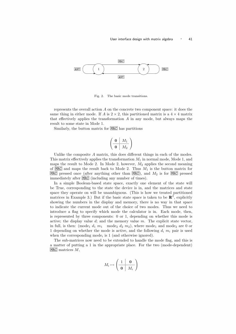
User interface design with matrix algebra · 41
ANY
1
2
MRC
MRC
ANY
Fig. 2. The basic mode transitions.
represents the overall action A on the concrete two component space: it does thesame thing in either mode. If A is 2 × 2, this partitioned matrix is a 4 × 4 matrixthat effectively applies the transformation A in any mode, but always maps theresult to some state in Mode 1.
Similarly, the button matrix for MRC has partitions
(0
....... M1...................0
....... M2
)Unlike the composite A matrix, this does different things in each of the modes.
This matrix effectively applies the transformation M1 in normal mode, Mode 1, andmaps the result to Mode 2. In Mode 2, however, M2 applies the second meaningof MRC and maps the result back to Mode 2. Thus M1 is the button matrix forMRC pressed once (after anything other than MRC ), and M2 is for MRC pressedimmediately after MRC (including any number of times).
In a simple Boolean-based state space, exactly one element of the state willbe True, corresponding to the state the device is in, and the matrices and statespace they operate on will be unambiguous. (This is how we treated partitionedmatrices in Example 3.) But if the basic state space is taken to be RR2, explicitlyshowing the numbers in the display and memory, there is no way in that spaceto indicate the current mode out of the choice of two modes. Thus we need tointroduce a flag to specify which mode the calculator is in. Each mode, then,is represented by three components: 0 or 1, depending on whether this mode isactive; the display value d; and the memory value m. The explicit state vector,in full, is then: (mode1 d1 m1 mode2 d2 m2), where mode1 and mode2 are 0 or1 depending on whether the mode is active, and the following di mi pair is usedwhen the corresponding modei is 1 (and otherwise ignored).
The sub-matrices now need to be extended to handle the mode flag, and this isa matter of putting a 1 in the appropriate place. For the two (mode-dependent)MRC matrices M ,
Mi →(
1....... 0...................
0....... Mi
)
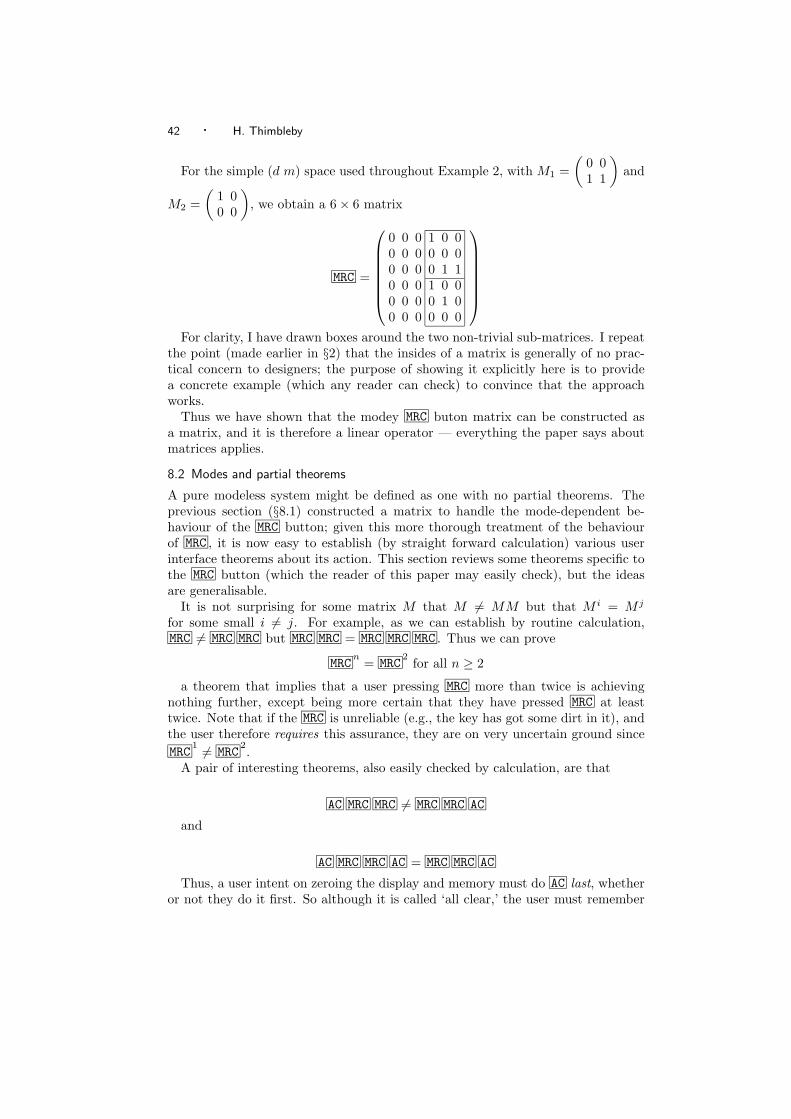
42 · H. Thimbleby
For the simple (d m) space used throughout Example 2, with M1 =(
0 01 1
)and
M2 =(
1 00 0
), we obtain a 6 × 6 matrix
MRC =
0 0 0 1 0 00 0 0 0 0 00 0 0 0 1 10 0 0 1 0 00 0 0 0 1 00 0 0 0 0 0
For clarity, I have drawn boxes around the two non-trivial sub-matrices. I repeat
the point (made earlier in §2) that the insides of a matrix is generally of no prac-tical concern to designers; the purpose of showing it explicitly here is to providea concrete example (which any reader can check) to convince that the approachworks.
Thus we have shown that the modey MRC buton matrix can be constructed asa matrix, and it is therefore a linear operator — everything the paper says aboutmatrices applies.
8.2 Modes and partial theorems
A pure modeless system might be defined as one with no partial theorems. Theprevious section (§8.1) constructed a matrix to handle the mode-dependent be-haviour of the MRC button; given this more thorough treatment of the behaviourof MRC , it is now easy to establish (by straight forward calculation) various userinterface theorems about its action. This section reviews some theorems specific tothe MRC button (which the reader of this paper may easily check), but the ideasare generalisable.
It is not surprising for some matrix M that M = MM but that M i = M j
for some small i = j. For example, as we can establish by routine calculation,MRC = MRC MRC but MRC MRC = MRC MRC MRC . Thus we can prove
MRCn
= MRC2
for all n ≥ 2
a theorem that implies that a user pressing MRC more than twice is achievingnothing further, except being more certain that they have pressed MRC at leasttwice. Note that if the MRC is unreliable (e.g., the key has got some dirt in it), andthe user therefore requires this assurance, they are on very uncertain ground sinceMRC
1 = MRC2.
A pair of interesting theorems, also easily checked by calculation, are that
AC MRC MRC = MRC MRC AC
and
AC MRC MRC AC = MRC MRC AC
Thus, a user intent on zeroing the display and memory must do AC last, whetheror not they do it first. So although it is called ‘all clear,’ the user must remember
User interface design with matrix algebra · 43
to do a memory clear with MRC before AC . This restriction potentially createsconfusion — AC clears the display and MRC pressed twice clears the memory, butto do both the user has to do them in the right order. Perhaps this explains whyusers press buttons repeatedly to ‘make sure.’
We could define matrices for the digit actions 1 , 2 and so on, for the userpressing digit keys (see the web site for details). We might naıvely expect for anydigit n that n MRC = MRC but this is not so as can be seen by premultiplying bothsides by MRC , thus: MRC n MRC = MRC MRC . The meaning of the right hand sideis now obviously that of a double MRC press, whereas the left hand side ends witha single press of MRC , so it is not surprising they are unequal — they must resultin different modes. This is an example of a ‘partial theorem’ (§4.2), partial overactions rather than states, because any action A other than MRC makes it true thatA n MRC = A MRC . More formally
∀ A = MRC , n ∈ 0..9: A n MRC = A MRC
A corollary of this theorem is that n can be a sequence of digits, not just a singledigit. In fact there are many such theorems. Some certainly represent facts aboutthe sort of behaviour that is likely to be confusing, because they are simple theorems(rules, equalities, involving only a few key presses) that are true most, but not allcases (specifically, the probably rare cases when the user presses MRC multiple timesin succession). If a user generalises ‘most of the time’ to ‘all of the time’ they willbe wrong. Since the theorems represent possible confusing behaviour, the design ofthe device should be appraised: can the design be changed to make the theoremsgeneral, or are the exceptions to the theorems necessary for some tasks the deviceshould support? The partial theorems also beg empirical questions: in practice,for a realistic balance of tasks, do users worry enough about the possibly rareconsequences to make a design change worthwhile?
8.3 Finding matrices from specifications
Computer algebra systems [11] are very powerful aids for doing mathematics. Thepurpose of this brief section is to show what can be done, using one such sys-tem, Mathematica [34], for concreteness. The code shown in below works fully asdescribed, and shows how we can go from a system implementation to a matrixeasily.
One way to implement an interactive system is to define each user action as afunction. In a computer algebra system like Mathematica, we can combine doingalgebra with programming functions directly. For example, a basic calculator witha memory (and a display for showing the user the results of their calculations!) mayhave a button AC , and we could write code such as
AC[display , memory , stuff ] := 0, memory, stuff;defining how AC operates on the state space: here, it simply sets the display to
zero. The ‘stuff’ are other components of the state space, such as whether the cal-culator is on or off, what outstanding operators are (so = knows what outstandingoperation to perform), and so on. We could have state components representingmore user-oriented factors, such as the time users take. For example, we know theposition of every button and so we could use Fitt’s Law to estimate minimum times
44 · H. Thimbleby
for the user to be able to move from pressing one button to the next: we couldhave a component for time, and a component representing the co-ordinates of thelast button pressed:
AC[display , memory , time , coords , stuff ] :=0, memory, time+moveTime[coords,10,20],10,20,stuff;
. . . which supposes the AC button is at position 10, 20. Notice how the state hasnow recorded the position of the user’s last press, namely at 10, 20, which in turnwill be used for the timing calculation for the next button press.
Definitions like these are sufficient to prototype interactive user interfaces foron-screen simulations, and, as Mathematica provides a full programming language,they can implement everything any device can do. The devices do not have tobe simple pushbutton type devices: it would be possible, say, to implement theautomatic suspension and enhanced braking systems of an advanced car and howthey interact with the user and driving conditions.
One way to obtain matrices from such definitions is to introduce a function projthat projects the full state space to vector spaces that represent the features ofparticular interest. We then ask Mathematica to find the matrices (if they exist)that correspond to the operations such as AC . If the matrices do not exist, thenwe have over-simplified in the projection or the generality of our assumptions. Inpractice it is easy to find out what the problems are, but in this paper I shall ignorethese technical details.
For example, we can define proj to extract just the display and memory contentsfrom the state space:
proj[display , memory , ] := display, memory;d = 6; example dimensions of full implementation state space
v = Array[Unique[], d]; symbolic state vector
d = 2; example dimensions of projected state
M = Array[Unique[], d,d]; symbolic matrix
M /. First@SolveAlways[proj[AC[v]] == proj[v].M, v]
Although the example here, to find the matrix corresponding to AC, is trivial (sothat I can show the full and complete code to solve the problem), a lot of workcan be done by the built-in function SolveAlways, which here is finding the matrixM such that proj(AC(v)) = proj(v)M for any v. With the definition of AC givenabove, this code obtains the matrix (
0 00 1
)— which is one of the matrices used in §6. The code above was an illustration of
how an arbitrary function (here, AC) acting on a 6 dimensional state space could beconverted to a 2×2 matrix. We don’t always want to do this! As a general purposeprogramming language, Mathematica allows the derivation to be generalised: wecan make AC a parameter, so we can find the matrix for any function, and we canuse nicer notation. We can define 〈f〉 to denote the matrix in the projected spacecorresponding to any function f implementing a user interface action. We can nowdirectly establish homomorphisms such as
User interface design with matrix algebra · 45
〈f g〉 = 〈g〉 · 〈f〉and we can use this notation to try them out in Mathematica.17 Here, if f was
the function implementing a calculator’s ‘add to memory’ button and g the functionthat implements the ‘subtract from memory’ button, the homomorphism here showsthat the matrix corresponding to the functional composition of the functions for thebuttons M+ and M- is equal to the product of the two matrices corresponding to eachbutton individually. If this equation is typed into Mathematica (after appropriatedefinition of the button functions), the answer True will be immediately obtained.We might establish many laws of this form to convince ourselves that all matriceswe are using to analyse a user interface are correctly modelling some system wehave implemented.
I gave examples like this in the Section 6, where simple 2 × 2 matrices wereused. With Mathematica we could easily do similar calculations with possibly hugematrices, derived reliably from real, working system definitions.
8.4 Design tools
Addressing the problems designers may have in using matrices in design is a matterof some urgency. This paper showed that established, ‘simple’ interactive systemsthat we all take for granted have non-trivial design problems. Whether these designproblems are always or sometimes actual problems for users — whether frequent,critical, trivial or merely irritating — is another matter, but it seems plausiblethat for many safety critical devices, such as electronic medical equipment andavionics systems it would be wise to assume that avoidable design problems shouldbe avoided. Currently, HCI professionals are not addressing these issues, and ifinteractive safety critical systems are not being designed to any higher standards,we should worry for the HCI consequences. In many areas, I would argue thatdesigners (or at least some people on the design teams) have an obligation to learnmatrix algebra or an equivalent formalism to ensure that the systems they buildreally do what they intend. Too often (in my opinion) the ‘HCI design’ team’s jobhas been seen as instructing the programmer and other technical designers: thesepeople need to be involved in the HCI design, just like all the other disciplines suchas anthropology.
Modelling techniques can be made available to designers, fully automated orpartly automated: one can imagine automatic design tools that help designers dowith ease some of the sorts of analysis that in this paper have been spelt out explic-itly and at length. Design tools can be used to generate accurate system models forpsychological modelling, and they would help reduce the gap between psychologicalanalysis and what a human-machine system actually does. Some initial progresshas already been achieved building matrix-based modelling tools [12].
See [26] for a wide range of design benefits from a matrix-based approach, inparticular showing concretely how a device can be simulated, analysed and have
17Details for programmers: The built-in function composition operator is defined as , and theequals operator is normally typed as == (to distinguish it from assignment, which is a single =
symbol). The size of the matrix and the choice of projection function can be defined in the usualway by using Assuming[].
46 · H. Thimbleby
various outline user manuals generated automatically and reliably.
8.5 Constructive use of matrices
The examples in this paper are all based on reverse engineering: if something isalready designed — indeed, an already working product — I can evidently presentits matrices, which might appear to be more-or-less pulling out of thin air. Buthow useful are matrices for a constructive design process for ordinary designers,who perhaps are not as interested in matrices as I am? Imagine a designer buildinga system: how would matrices help during, rather than after building it? Whatproperties should be explored over unfinished designs?
In an unfinished design, we have to distinguish between partial theorems andtheorems that are tentatively partial because the design is not complete. As wemake forward design decisions, the design is not complete. This is a stark contrast tothe fully-informed hindsight that reverse engineering affords. Whilst the hindsightof this paper could improve iterative design (e.g., if the manufacturers producenew models based on the existing models), it is not so clear how it contributes toinnovation when less information is available.
It is not obvious that matrices can easily define all systems of interest, so anyathe research and development programme that developed a tool could anticipatemeeting a future barrier. It is possible that a designer must have some feature(or feature interaction) that the proposed tool cannot support. This is a risk. Incontrast, if the design notation was general purpose (e.g., a programming languagelike Java) rather than matrix algebra, then the research investment would obviouslybe worthwhile: there are no likely barriers to progress — and certainly no self-imposed barriers that competitors could avoid. The suggestion of §8.3 is thatsome general purpose languages could support a matrix based design approachautomaticaly, but, even so, building tools for them would be a non-trivial task (andprobably pointless) because it requires implementing powerful computer algebraengines.
To summarise: developing a good design tool for matrices will require consider-able commitment (e.g., motivated by a safety critical design problem) and will haveto be done under assumptions of uncertain payoffs in the long run. In contrast,and competing with such investment of effort, there are many Rapid ApplicationDevelopment (RAD) environments for general purpose systems such as Java.
8.6 Model checking and other approaches
Model checking and theorem proving are standard techniques for establishing thatsystem specifications have desired properties. Typically they require expertise be-yond basic matrix algebra, but the tradeoffs are very different — both approachesare very well supported with sophisticated (though specialised) tools. Useful refer-ences to follow are [8] for model checking, and [9] for theorem proving applicationsin HCI contexts. Unlike the simple matrix algebra approach, promoted by thispaper, making effective use of either model checking or theorem proving requireslearning the particular notations used by tools that support the approaches, as wellas having a sophisticated understanding of the underlying mathematical logics.
User interface design with matrix algebra · 47
8.7 Modes and the ordering states
The text of the paper explained how partitioned matrices can be used to handlemodes and subsystems well. We gave the impression that any system can be han-dled by partitioning. A partition is a partial ordering of states; for example, if asystem has two modes A and B, then we could partition the button matrices on theassumption that all states in mode A are numbered less than all states in mode B.Then we can easily write down a partitioned matrix. A different pair of modes, sayB and C, may impose a different partial ordering, and in principle it is possible forthere to be no consistent total ordering of states for all three modes. At first sight,this problem does not matter, since if M is a partitioned matrix separating modesA and B, we might use a matrix N such that M = PNPT to deal with modes Band C. (See §7.3.)
We can thus handle ‘inconsistent’ modes with more than one matrix (in thisexample, M and N , but M = N even though they represent the same buttonmatrix). Is it ever the case that a user needs to understand all inconsistent modes atonce? If so, there can be no single partitioned matrix that represents this situation.A counter argument is that if there is no such matrix, then we can claim the systemis badly designed. If it really is the case that such a system is ‘bad’ (for some sensesof ‘bad’), then a design notation that avoids such problems is to be welcomed. Onthe other hand, it is possible that some tasks require inconsistent modes for goodusability reasons — and as this is a case that would be awkward to handle usingmatrices we might take it as an argument against matrix algebra in user interfacedesign.
I know of no such examples, but finding any would either help sharpen theboundaries of matrix algebra as applied to user interface design, or perhaps wouldcompletely undermine the whole enterprise.
8.8 Complexity theory
The set of button matrices defining a system are (in an important sense) a completeinteraction definition. The matrices often have structure that can be exploited tomake more compact definitions. In general, a set of matrices can be compresseddepending on the Kolmogorov complexity, which is therefore a measure of the formalcomplexity of the interactive system. If a user is to learn how to use a system indetail they have to know the matrices or equivalent (and anything equivalent hasthe same Kolmogorov complexity), so this complexity is a theoretical low boundon the cognitive resources the user needs: how hard this knowledge is to acquire,remember and recall for use.
Kolmogorov complexity is not the only measure of complexity. Fisher complexityis based on a notion of observation: this might be relevant here, as we are concernedwith the complexity of the user model given that users observe system transitionsand their effects. Finding a complexity metric that is well defined and has someor all of the appropriate cognitive properties would be a major but worthwhileresearch project.
8.9 Pseudo inverses
If a matrix is singular it has no inverse, but this is a strict criterion that may havelittle relevance to a user (see §4.2): if a user can undo an operation almost all of
48 · H. Thimbleby
the time, rather than all of the time, this may be sufficient. For example, a buttonmay have an effective inverse except when the device is off — which means a userwould probably not have tried the action that had no inverse!
A more realistic criterion if A is singular is to find a matrix B such that AB ≈ Iwithin some specified accuracy, perhaps weighted with known or guessed probabil-ities of users having the device in certain states. Of all the matrices B that satisfythis, to find one that is ‘most’ relevant to users is a challenge: for example theeasier B is to factorise in terms of existing button matrices the easier a user willbe able to undo the action A .
There are standard generalised inverses, which exist even when a matrix is sin-gular. For example, the Moore-Penrose pseudo inverse of A, written A(−1), satisfiesAA(−1)A = A. (In the special case that A is invertible, then A(−1) = A−1.) Thisequation has various user interface design readings, for instance: doing any se-quence of actions that are equivalent to A
(−1)after first doing A can be undone
by doing A again; or it can be read as: if a user does A and changes their mind(perhaps because A was thought to be a slip), they can do B , and if they changetheir minds back (perhaps because doing A was not a slip — doing A was in factcorrectly intended) then they need only do A again. The Moore-Penrose pseudoinverse is defined to minimise the sum of the squares of all ‘errors’ in AA(−1) − I,so this is a form of partial theorem, AA(−1) ≈ I.
The pseudo inverse suggests new avenues of research, including the following:
—Given a partial theorem, find a design (from a matrix) that minimises some mea-sure (in the Moore-Penrose, minimise the sum squared error). What measuresare effective?
—How should the measure be weighted from empirical data of user behaviour?
—The partial theorem here, namely interpretations of ABA = A, is clearly one ofa class of interesting theorems, some of which may more closely fit use scenarios,particularly in representing forms of error recovery. Defining an effective reper-toire of theorems, together with the conditions under which they are applicable,would be very fruitful.
—and what other concepts from matrix algebra can be recruited to address userinterface design issues?
9. CONCLUSIONS
Standard matrix algebra gives detailed and specific insight into user interface designissues. Our use of matrix algebra in this paper reveals persuasively that someapparently trivial user interfaces are very complex. I suggest that the arbitrarycomplexity we uncovered in some systems is a sign of bad design (it certainly isbad engineering, if not bad user interface design), and that the arbitrary complexitybegs usability questions that should be addressed by employing empirical evaluationmethods.
This paper raises a question:
User interface design with matrix algebra · 49
If some user interface design issues are so complex they are only understandablewith the help of algebra (or other mathematical approaches), how can ordinaryusability evaluation methods (which ignore such formalisms) reliably help?
In areas of safety critical systems, this is a very serious question. At least oneresponse is to design systems formally to be simpler, so that there are plausiblyno such overwhelmingly complex usability issues to find, fix or palliate. Anotherresponse is to use formal approaches, such as matrix algebra, to support design sothat designers know what they implementing: the results of usability evaluationscan then be used to help fix rather than disguise problems. Even where formalmethods appear not to be applicable, at least the designers would know, and theywould then take extra precautions, whether in their design processes or in the designof the user interface features.
Reasoning about user interfaces at the required level of detail is usually verytedious and error prone — and is usually avoided! Matrices enable calculations tobe made easily and reliably, and indeed also support proofs, of both general anddetailed user interface behaviour.
Very likely, as suggested in the box above, the extreme complexity of doing sometasks (such as stoing to memory) are why users, designers and usability professionalshave all but ignored the poor usability of some devices. They are far too hard tothink about! The intricacy and specificity of feature interactions (as in the digitalmultimeter) apparently encourage problems to be overlooked, or, more likely, neverto be discovered.
For the time being it remains an unanswered empirical question whether theapparently unnecessary complexities of the Casio calculator or the Fluke 185 makethem superior designs than ones that we might have reached driven by the æstheticsof matrix algebra. However, it is surely an advantage of an algebraic approach thatknown (and perhaps rare) interaction problems can be eliminated at the designstage, and doing so will strengthen the validity of any further insights gained fromemploying empirical methods. Certainly, in comparision with informal evaluations(e.g., [25], which comments on other Fluke instruments), a matrix algebra approachcan provide specific insights into potential design improvement, and ones moreoverthat are readily implemented. There is much scope for usability studies of betteruser interfaces of well-defined systems, rather than (as often happens) studies ofhow users cope with complex and poorly defined interfaces.
Many centuries of mathematics have refined its tools for effective and reliablehuman use — matrix algebra is just one example — and this is a massive resourcethat user interface designers should draw on to the full.
Acknowledgements
Harold Thimbleby is a Royal Society-Wolfson Research Merit Award Holder, andacknowledges their support. The author is also grateful for very constructive com-ments from David Bainbridge, Ann Blandford, George Buchanan, Paul Cairns,George Furnas, Jeremy Gow (who suggested partial theorems), Michael Harrison,Mark Herbster, Tony Hoare, Matt Jones and Peter Pirolli.
50 · H. Thimbleby
REFERENCES
[1] M. A. Addison & H. Thimbleby, “Intelligent Adaptive Assistance and Its AutomaticGeneration,” Interacting with Computers, 8(1), pp51–68, 1996.
[2] J. L. Alty, “The Application of Path Algebras to Interactive Dialogue Design,” Behaviourand Information Technology, 3(2), pp119–132, 1984.
[3] J. R. Anderson & C. Lebiere, The Atomic Components of Thought, Lawrence ErlbaumAssociates, 1998.
[4] A. Blandford & R. M. Young, “Specifying User Knowledge for the Design of InteractiveSystems,” Software Engineering Journal, 11(6), pp323–333, 1996.
[5] J. R. Brown, Philosophy of Mathematics, Routledge, 1999.
[6] C. G. Broyden, Basic Matrices, Macmillan, 1975.
[7] S. K. Card, T. P. Moran, & A. Newell, The Psychology of Human-Computer Interaction,Lawrence Erlbaum Associates, Hillsdale, NJ, 1983.
[8] E. M. Clarke, Jr., O. Grumberg & D. A. Peled, Model Checking, MIT Press, 1999.
[9] P. Curzon & A. Blandford, “Detecting Multiple Classes of User Errors,” M. Reed Little &L. Nigay, editors, Engineering for Human-Computer Interaction, LNCS 2254, pp57–71,Springer Verlag, 2001.
[10] A. Dix, J. Finlay, G. Abowd & R. Beale, Human-Computer Interaction, 2nd. ed., PrenticeHall, 1998.
[11] J. von zur Gathen & J. Gerhard, Modern Computer Algebra, Cambridge University Press,2003.
[12] J. Gow & H. Thimbleby, “MAUI: An Interface Design Tool Based on Matrix Algebra,”ACM Conference on Computer Aided Design of User Interfaces, CADUI IV, edited byR. J. K. Jacob, Q. Limbourg & J. Vanderdonckt, pp81–94 (pre-proceedings pagenumbers), 2004.
[13] H. R. Hartson, A. Siochi & D. Hix, “The UAN: A User Oriented Representation for DirectManipulation Interface Designs,” ACM Transactions on Information Systems, 8(3),pp181–203, 1990.
[14] I. Horrocks, Constructing the User Interface with Statecharts, Addison-Wesley, 1999.
[15] M. Y. Ivory & M. A. Hearst, “The State of the Art in Automating Usability Evaluation ofUser Interfaces,” ACM Computing Surveys, 33(4), pp470–516, 2001.
[16] S. C. Johnson, “Yacc: Yet Another Compiler-Compiler,” UNIX Programmer’s Manual, 2,Holt, Rinehart, and Winston, New York, NY, pp353–387, 1979.
[17] D. Kieras & P.G. Polson, “An Approach to the Formal Analysis of User Complexity,”International Journal of Man-Machine Studies, 22(4), pp365–394, 1985.
[18] D. E. Knuth, “Two Notes on Notation,” American Mathematical Monthly, 99(5),pp403–422, 1992.
[19] L. Lamport, “TLA in Pictures,” IEEE Transactions on Software Engineering, 21(9),pp768–775, 1995.
[20] B. Myers, “Past, Present, and Future of User Interface Software Tools,” in J. M. Carroll,editor, Human-Computer Interaction in the New Millenium, Addison-Wesley, 2002.
[21] W. M. Newman, “A System for Interactive Graphical Programming,” Proceedings 1968Spring Joint Computer Conference, 47–54, American Federation of InformationProcessing Societies, 1969.
[22] D. L. Parnas, “On the Use of Transition Diagrams in the Design of a User Interface for anInteractive Computer System,” Proceedings 24th. ACM National Conference,pp379–385, 1964.
[23] S. J. Payne, “Display-Based Action at the User Interface,” International Journal ofMan-Machine Studies, 35(3), pp275–289, 1991.
[24] P. Pirolli & S. K. Card, “Information Foraging Models of Browsers for Very LargeDocument Spaces,” ACM Proceedings Advanced Visual Interfaces, AVI’98, 83–93, 1998.
[25] J. Raskin, The Humane Interface, Addison-Wesley, 2000.
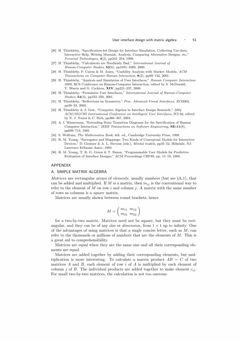
User interface design with matrix algebra · 51
[26] H. Thimbleby, “Specification-led Design for Interface Simulation, Collecting Use-data,Interactive Help, Writing Manuals, Analysis, Comparing Alternative Designs, etc,”Personal Technologies, 4(2), pp241–254, 1999.
[27] H. Thimbleby, “Calculators are Needlessly Bad,” International Journal ofHuman-Computer Studies, 52(6), pp1031–1069, 2000.
[28] H. Thimbleby, P. Cairns & M. Jones, “Usability Analysis with Markov Models, ACMTransactions on Computer Human Interaction, 8(2), pp99–132, 2001.
[29] H. Thimbleby, “Analysis and Simulation of User Interfaces,” Human Computer Interaction2000, BCS Conference on Human-Computer Interaction, edited by S. McDonald,Y. Waern and G. Cockton, XIV, pp221–237, 2000.
[30] H. Thimbleby, “Permissive User Interfaces,” International Journal of Human-ComputerStudies, 54(3), pp333–350, 2001.
[31] H. Thimbleby, “Reflections on Symmetry,” Proc. Advanced Visual Interfaces, AVI2002,pp28–33, 2002.
[32] H. Thimbleby & J. Gow, “Computer Algebra in Interface Design Research,” 2004ACM/SIGCHI International Conference on Intelligent User Interfaces, IUI 04, editedby N. J. Nunes & C. Rich, pp366–367, 2004.
[33] A. I. Wasserman, “Extending State Transition Diagrams for the Specification of HumanComputer Interaction,” IEEE Transactions on Software Engineering, SE-11(8),pp699–713, 1985.
[34] S. Wolfram, The Mathematica Book, 4th. ed., Cambridge University Press, 1999.
[35] R. M. Young, “Surrogates and Mappings: Two Kinds of Conceptual Models for InteractiveDevices,” D. Gentner & A. L. Stevens (eds.), Mental models, pp35–52, Hillsdale, NJ:Lawrence Erlbaum Assoc, 1983.
[36] R. M. Young, T. R. G. Green & T. Simon, “Programmable User Models for PredictiveEvaluation of Interface Designs,” ACM Proceedings CHI’89, pp. 15–19, 1989.
APPENDIX
A. SIMPLE MATRIX ALGEBRA
Matrices are rectangular arrays of elements, usually numbers (but see §A.1), thatcan be added and multiplied. If M is a matrix, then mij is the conventional way torefer to the element of M on row i and column j. A matrix with the same numberof rows as columns is a square matrix.
Matrices are usually shown between round brackets, hence
M =(
m11 m12
m21 m22
)for a two-by-two matrix. Matrices need not be square, but they must be rect-
angular, and they can be of any size or dimension, from 1 × 1 up to infinity. Oneof the advantages of using matrices is that a single concise letter, such as M , canrefer to the thousands or millions of numbers that are the elements of M . This isa great aid to comprehensibility.
Matrices are equal when they are the same size and all their corresponding ele-ments are equal.
Matrices are added together by adding their corresponding elements, but mul-tiplication is more interesting. To calculate a matrix product AB = C of twomatrices A and B, each element of row i of A is multiplied by each element ofcolumn j of B. The individual products are added together to make element cij .For small two-by-two matrices, the calculation is not too onerous:
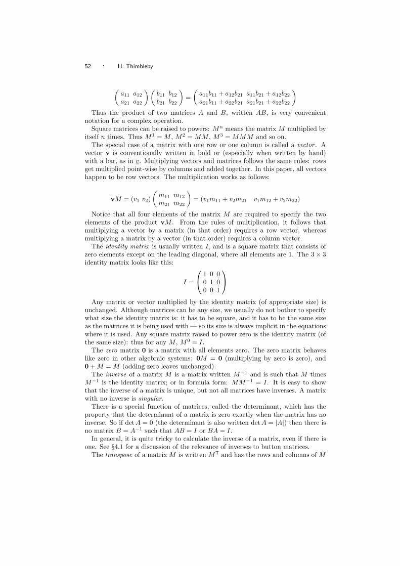
52 · H. Thimbleby
(a11 a12
a21 a22
) (b11 b12
b21 b22
)=
(a11b11 + a12b21 a11b21 + a12b22
a21b11 + a22b21 a21b21 + a22b22
)Thus the product of two matrices A and B, written AB, is very convenient
notation for a complex operation.Square matrices can be raised to powers: Mn means the matrix M multiplied by
itself n times. Thus M1 = M , M2 = MM , M3 = MMM and so on.The special case of a matrix with one row or one column is called a vector . A
vector v is conventionally written in bold or (especially when written by hand)with a bar, as in v. Multiplying vectors and matrices follows the same rules: rowsget multiplied point-wise by columns and added together. In this paper, all vectorshappen to be row vectors. The multiplication works as follows:
vM = (v1 v2)(
m11 m12
m21 m22
)= (v1m11 + v2m21 v1m12 + v2m22)
Notice that all four elements of the matrix M are required to specify the twoelements of the product vM . From the rules of multiplication, it follows thatmultiplying a vector by a matrix (in that order) requires a row vector, whereasmultiplying a matrix by a vector (in that order) requires a column vector.
The identity matrix is usually written I, and is a square matrix that consists ofzero elements except on the leading diagonal, where all elements are 1. The 3 × 3identity matrix looks like this:
I =
1 0 00 1 00 0 1
Any matrix or vector multiplied by the identity matrix (of appropriate size) is
unchanged. Although matrices can be any size, we usually do not bother to specifywhat size the identity matrix is: it has to be square, and it has to be the same sizeas the matrices it is being used with — so its size is always implicit in the equationswhere it is used. Any square matrix raised to power zero is the identity matrix (ofthe same size): thus for any M , M0 = I.
The zero matrix 0 is a matrix with all elements zero. The zero matrix behaveslike zero in other algebraic systems: 0M = 0 (multiplying by zero is zero), and0 + M = M (adding zero leaves unchanged).
The inverse of a matrix M is a matrix written M−1 and is such that M timesM−1 is the identity matrix; or in formula form: MM−1 = I. It is easy to showthat the inverse of a matrix is unique, but not all matrices have inverses. A matrixwith no inverse is singular.
There is a special function of matrices, called the determinant, which has theproperty that the determinant of a matrix is zero exactly when the matrix has noinverse. So if detA = 0 (the determinant is also written detA = |A|) then there isno matrix B = A−1 such that AB = I or BA = I.
In general, it is quite tricky to calculate the inverse of a matrix, even if there isone. See §4.1 for a discussion of the relevance of inverses to button matrices.
The transpose of a matrix M is written MT and has the rows and columns of M
User interface design with matrix algebra · 53
swapped. Thus
MT =(
m11 m21
m12 m22
)which swaps the off-diagonal elements m12 and m21. The elements on the diag-
onal are not changed when a matrix is transposed.
A.1 Partitions
Matrices are normally considered as arrays of numbers; in fact any values can beused, provided they can be ‘added’ and ‘multiplied.’ Matrices themselves have theseproperties, and therefore matrices can be built up, or partitioned, out of elementsthat are themselves matrices, or submatrices. Consider a matrix M partitioned intofour submatrices:
M =
(M11
....... M12...........................M21
....... M22
)Partitioned matrices are sometimes called block matrices, as their elements form
blocks. In this paper, I use dotted lines like ............. to visually clarify the structureof a partitioned matrix. The dotted lines have no mathematical significance.
The submatrices, M11 etc, need not all be the same size, though they mustconform (i.e., be the right size) for the operations required of them. Thus if thispartitioning of M is used to multiply a state vector s, partitioned as (s1
... s2), thenthe number of columns of s1 must equal the number of rows of M11 etc. If s andM conform in this way, the partitions can be multiplied out:
(s1
....... s2
) (M11
....... M12...........................M21
....... M22
)=
(s1M11 + s2M21
....... s1M12 + s2M22
)Mathematically this is necessarily correct, regardless of the structure of the FSM
and buttons we might be describing.We can see, for example, that if M21 is zero, the complete behaviour of the s1
component of the system can be understood even ignoring the s2 component:
(s1
....... s2
) (M11
....... M12...........................0
....... M22
)=
(s1M11
....... s1M12 + s2M22
)Whether a user fully understands s1 or not (they may understand a subparti-
tion of it), no knowledge of s2 need interfere with their understanding. Whateverbefalls the s2 component, we can abstract the properties of s1 and M11 indepen-dently. Similarly we can understand the s2 component of the system completelyeven ignoring the s1 component provided M12 is zero, and so on. Since it seemsdesirable to design user interfaces where users can understand parts of the sys-tem independently, designing systems with zero submatrices is a powerful designheuristic. In fact, it is not just a design heuristic but a heuristic for calculation: if a
54 · H. Thimbleby
matrix can be factored into partitioned matrices with ‘big enough’ zero blocks, mul-tiplication, as a calculation, can be speeded up. Whether this means that buttonmatrices with large zero blocks are ‘easier to think about’ is an interesting questionfor investigation.
A.2 Algebraic properties
Algebra looks at the properties of matrices, rather than how calculations are donewith them — this is why algebra is an appropriate approach to user interaction: weare interested in the properties of interaction, which matrix algebra defines. We arenot interested in how the user thinks, but we have a convenient way to calculatewith matrices (which is not available to the typical user).
Here are a few basic algebraic properties:
—Any matrix M times the identity is itself: MI = IM = I.—The inverse of a matrix M is written M−1, and MM−1 = M−1M = I. The
inverse of a matrix is unique. Not all matrices have inverses, however. Inversesare closely related to undo; see §4.1.
—Matrix multiplication does not commute. In general, AB = BA, although forsome matrices AB = BA. For any matrix M , MI = IM .
—Matrix multiplication is associative: (AB)C = A(BC), hence we can write ABCwithout ambiguity. Associativity is closely related to modelessness; see §6.
—If a matrix has numerical elements, its determinant is a number. If the determi-nant of M is zero, det M = 0, then M is singular.
—The determinant of a matrix product is the product of the determinants: detAB =detA detB.
—Matrices do not support division; AB makes no sense, since in general AB−1 =
B−1A.—Transposition reverses the order of multiplication: (AB)T = BTAT. Other laws
for transposition include IT = I, and for any matrix MTT = M .
B. FROM FINITE STATE MACHINES TO MATRIX ALGEBRA
Finite state machines (FSMs) are a basic formalism for interactive systems. Fi-nite state machines have had a long history in user interface design, starting withNewman [21] and Parnas [22] in the 1960s, and reaching a height of interest inuser interface management systems (UIMS) work [33]; see [10] for a textbook in-troduction with applications of FSMs in HCI. FSMs can handle paralleism, non-determinism, and so forth (many parallel reactive programming languages compileinto FSM implementations).
Now the concerns of HCI have moved on [20], beyond any explicit concern withFSMs — a continual, technology-driven pressure, but one that tends to leave openunfinished theoretical business.
FSMs are often drawn as transition diagrams. A transition diagram consists ofcircles and arrows connecting the circles; the circles represent states, and the arrowsrepresent transitions between states. Typically both the circles and the arrows arelabelled with names. A finite state machine is in one state at a time, representedby being ‘in’ one circle. When an action occurs the corresponding arrow from that
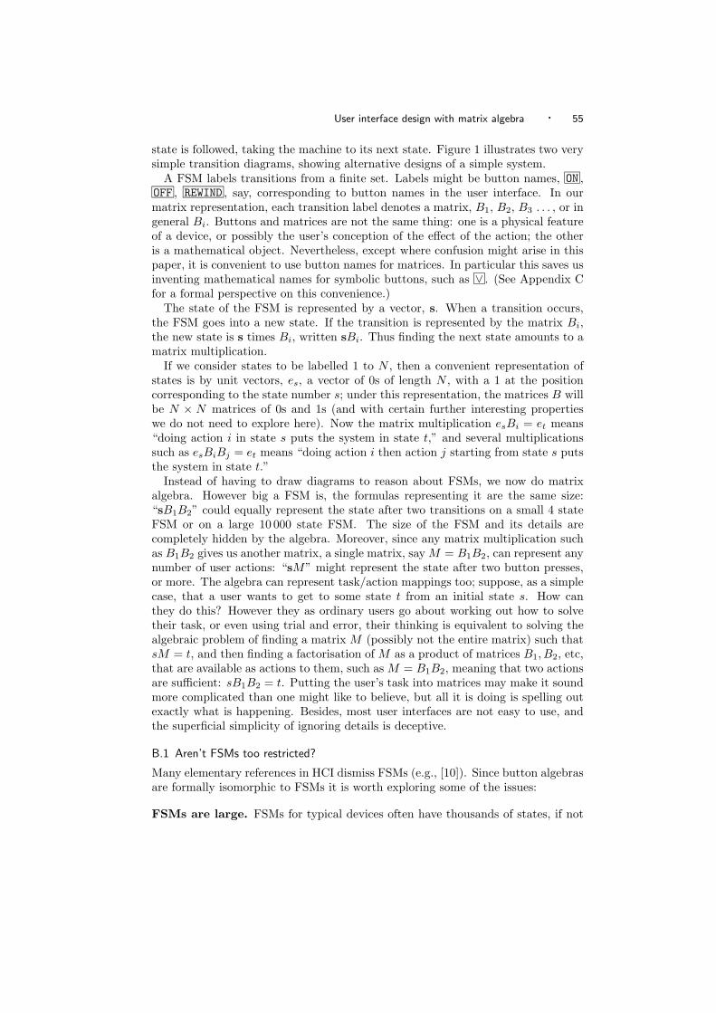
User interface design with matrix algebra · 55
state is followed, taking the machine to its next state. Figure 1 illustrates two verysimple transition diagrams, showing alternative designs of a simple system.
A FSM labels transitions from a finite set. Labels might be button names, ON ,OFF , REWIND , say, corresponding to button names in the user interface. In ourmatrix representation, each transition label denotes a matrix, B1, B2, B3 . . . , or ingeneral Bi. Buttons and matrices are not the same thing: one is a physical featureof a device, or possibly the user’s conception of the effect of the action; the otheris a mathematical object. Nevertheless, except where confusion might arise in thispaper, it is convenient to use button names for matrices. In particular this saves usinventing mathematical names for symbolic buttons, such as ∨ . (See Appendix Cfor a formal perspective on this convenience.)
The state of the FSM is represented by a vector, s. When a transition occurs,the FSM goes into a new state. If the transition is represented by the matrix Bi,the new state is s times Bi, written sBi. Thus finding the next state amounts to amatrix multiplication.
If we consider states to be labelled 1 to N , then a convenient representation ofstates is by unit vectors, es, a vector of 0s of length N , with a 1 at the positioncorresponding to the state number s; under this representation, the matrices B willbe N × N matrices of 0s and 1s (and with certain further interesting propertieswe do not need to explore here). Now the matrix multiplication esBi = et means“doing action i in state s puts the system in state t,” and several multiplicationssuch as esBiBj = et means “doing action i then action j starting from state s putsthe system in state t.”
Instead of having to draw diagrams to reason about FSMs, we now do matrixalgebra. However big a FSM is, the formulas representing it are the same size:“sB1B2” could equally represent the state after two transitions on a small 4 stateFSM or on a large 10 000 state FSM. The size of the FSM and its details arecompletely hidden by the algebra. Moreover, since any matrix multiplication suchas B1B2 gives us another matrix, a single matrix, say M = B1B2, can represent anynumber of user actions: “sM” might represent the state after two button presses,or more. The algebra can represent task/action mappings too; suppose, as a simplecase, that a user wants to get to some state t from an initial state s. How canthey do this? However they as ordinary users go about working out how to solvetheir task, or even using trial and error, their thinking is equivalent to solving thealgebraic problem of finding a matrix M (possibly not the entire matrix) such thatsM = t, and then finding a factorisation of M as a product of matrices B1, B2, etc,that are available as actions to them, such as M = B1B2, meaning that two actionsare sufficient: sB1B2 = t. Putting the user’s task into matrices may make it soundmore complicated than one might like to believe, but all it is doing is spelling outexactly what is happening. Besides, most user interfaces are not easy to use, andthe superficial simplicity of ignoring details is deceptive.
B.1 Aren’t FSMs too restricted?
Many elementary references in HCI dismiss FSMs (e.g., [10]). Since button algebrasare formally isomorphic to FSMs it is worth exploring some of the issues:
FSMs are large. FSMs for typical devices often have thousands of states, if not
56 · H. Thimbleby
more. The size of a FSM is not a concern for this paper, though obviously itwould be a serious problem if one wanted to draw the corresponding transitiondiagram (though [19] provides a solution). No finite state machines have beenor need to be drawn for this paper (though I drew two in the Figures for purelyexplanatory purposes).
FSMs are unstructured. FSMs are indeed unstructured. Matrices, however,can be partitioned; Example 3 in this paper and the handling of the MRC but-ton (in §mrcap) shows how a hierarchical definition can be constructed usingmatrices, and hence how a very large system can be modelled.
FSMs are finite. FSMs are finite and therefore formally less powerful than infi-nite computational models such as push down automata (PDAs). A calculatorusing brackets is readily modelled as a PDA, and therefore one might think it isnot a FSM. However all physically realisable digital devices are FSMs, whetheror not it is convenient to model them explicitly as such. The matrix approachcan be used to model finite PDAs.
FSMs are not relevant to users. Certainly, FSMs are mathematical structuresand they do not exist in any concrete form for users. Users need not be expectedto reason about the behaviour of FSMs: they are typically far too big, and asa formalism they are so versatile that they have no structure that really helpsthinking about them. Obviously some FSMs will have interesting structure(e.g., ones designed using Statecharts [14]), but in these cases it is easier tothink about the structure than the FSM itself. What the user can see, however,is buttons and their effects. This paper shows that each button is a matrix; itthus turns out that users — whether they know it or not — are doing matrixalgebra when they press buttons.
Systems are not implemented as FSMs. Most systems are implemented in adhoc ways, and determining any model from them is hard if not impossible.In this sense, FSMs suffer from problems no different from any other formalapproach. Better, one would start with the formal model and derive (preferablyautomatically) the implementation.FSMs and their button matrices are sparse. There are many techniques for rep-resenting them in a compressed form, and many of these techniques (e.g., blackbox linear algebra [11]) are equivalent to conventional program implementationtechniques where the FSM structure is not explicit.
FSM models are impossible to determine. On the contrary, if systems aredeveloped rigorously it is not hard to determine finite models of user interfacesfrom them: it is a routine application of a computer algebra system — see §8.3for further details.
Overall, there is a balance to be had. It may not be possible to represent all aspectsof a system in a clear way using matrix algebra. But representing how componentsof state are manipulated by the user can nevertheless reveal complications in theway the device works, complications that may perhaps cause problems for users,and will certainly highlight issues designers should consider. Indeed, we can talkabout user actions and their algebra without referring to state, and thus, at leastalgebraically, we can hide the state size issues. Further arguments can be foundin [28].

User interface design with matrix algebra · 57
C. FORMAL DEFINITIONS AND BASIC PROPERTIES
It perhaps helps some readers to give at least one formal definition — there aremany ways and styles to formalise the approach.
A FSM is a tuple F = 〈S, Σ, S0, δ〉, where S is a set of states, Σ an alphabet(e.g., actions, buttons), S0 ⊆ S the set of initial states, δ ⊆ S×Σ×S the transitionrelation. The definition is standard.
This is a mathematical definition; we are not (in this Appendix) concerned withwhat F is or how it is realised, only with its formal properties. We may think ofF as a box with buttons and electronics in it, but it could equally be a human, arobot, or a horse, or any finite discrete system where we are interested in its actionsand their laws.
For some issues of human computer interaction, we might want to introducerefinements to the FSM definition, such as representations for states. For example,the user can see an image of the state i(s) on most systems (on simple systems imay be a bijection, otherwise users cannot be certain of the state).
Choose n: 1..|S| ↔ S, a bijection, taking numbers to states.Let B: Σ → M give the button matrix an action denotes. Specifically, for the
action σ ∈ Σ the button matrix B = B[[σ]]
over Booleans is defined by the charac-teristic function of the transition relation:
bij = δ(n(i), σ, n(j))
So for action σ, B is a matrix of Boolean values, with True elements when theFSM has a transition for the action.
Analogously we define an intial state vector v:
vi = n(i) ∈ S0
Theorem. A FSM is isomorphic to a set of button matrices B[[σ]]:σ ∈
Σ equipped with matrix multiplication together with an initial statevector v.
Matrices can have elements over any ring, Booleans, integers, reals, and so on.It is briefer to write 0 and 1 instead of False and True, a convention we adopt. Wetake the ring to be implicit from the context. In the body of the paper, explicituse of B was avoided; hence by convention, for a button ∨ we simply denotethe corresponding button matrix ∨ instead of B
[[∨
]]; thus avoiding typographical
clutter.Two important properties can immediately be stated.
—A deterministic action is one that has no more than one 1 in each row of itsmatrix. If a FSM is deterministic, then the initial state S0 is a singleton (i.e.,there is exactly one initial state), and the transition relation δ is a functionS × Σ → S. The paper only considers deterministic FSMs.
—An unguarded action is one that has at least one 1 in each row of its matrix.Normally we are interested in deterministic, unguarded actions. A guarded actionis one that cannot be attempted in some states: this is unusual, but can happenwhen systems have protections or guards that stop users reaching some buttons.Normally, of course, a user can try to do actions whether or not the designer
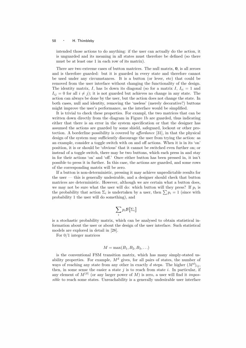
58 · H. Thimbleby
intended those actions to do anything: if the user can actually do the action, itis unguarded and its meaning in all states must therefore be defined (so theremust be at least one 1 in each row of its matrix).
There are two extreme cases of button matrices. The null matrix, 0, is all zeroesand is therefore guarded: but it is guarded in every state and therefore cannotbe used under any circumstances. It is a button (or lever, etc) that could beremoved from the user interface without changing the functionality of the design.The identity matrix, I, has 1s down its diagonal (so for a matrix I, Iii = 1 andIij = 0 for all i = j); it is not guarded but achieves no change in any state. Theaction can always be done by the user, but the action does not change the state. Inboth cases, null and identity, removing the ‘useless’ (merely decorative?) buttonsmight improve the user’s performance, as the interface would be simplified.
It is trivial to check these properties. For exampl, the two matrices that can bewritten down directly from the diagram in Figure 1b are guarded, thus indicatingeither that there is an error in the system specification or that the designer hasassumed the actions are guarded by some shield, safeguard, lockout or other pro-tection. A borderline possibility is covered by affordance [31], in that the physicaldesign of the system may sufficiently discourage the user from trying the action: asan example, consider a toggle switch with on and off actions. When it is in its ‘on’position, it is or should be ‘obvious’ that it cannot be switched even further on; orinstead of a toggle switch, there may be two buttons, which each press in and stayin for their actions ‘on’ and ‘off.’ Once either button has been pressed in, it isn’tpossible to press it in further. In this case, the actions are guarded, and some rowsof the corresponding matrix will be zero.
If a button is non-deterministic, pressing it may achieve unpredictable results forthe user — this is generally undesirable, and a designer should check that buttonmatrices are deterministic. However, although we are certain what a button does,we may not be sure what the user will do: which button will they press? If pi isthe probability that action Σi is undertaken by a user, then
∑pi = 1 (since with
probability 1 the user will do something), and
∑i
piB[[Σi
]]is a stochastic probability matrix, which can be analysed to obtain statistical in-formation about the user or about the design of the user interface. Such statisticalmodels are explored in detail in [28].
For 0/1 integer matrices
M = max(B1, B2, B3, . . .)
is the conventional FSM transition matrix, which has many simply-stated us-ability properties. For example, Md gives, for all pairs of states, the number ofways of reaching any state from any other in exactly d steps. The higher (Md)ij ,then, in some sense the easier a state j is to reach from state i. In particular, ifany element of M |S| (or any larger power of M) is zero, a user will find it impos-sible to reach some states. Unreachability is a generally undesirable user interface

User interface design with matrix algebra · 59
property. These two examples are provided as simple illustrations of the way thatformal methods can make different types of claim: either plausible or precise usabil-ity claims. In the case of a user finding some tasks ‘easier’ the higher some elementsof Md, this in general will depend on the particular user interface and other concreteissues. Thus this claim raises an empirically testable question for any particularhuman/system configuration or task scenario. On the other hand, if a system hasunreachable states, all users will find certain tasks impossible regardless of specificcircumstances — and knowing this requires no empirical testing.