user-centered standardization of industrial … (by others)/hci...user-centered standardization of...
TRANSCRIPT
User-Centered Standardization of IndustrialProcess Control User Interfaces
Tobias KomischkeCorporate Technology
Information and CommunicationUser Interface Design
Siemens AG
Michael BurmesterUsability Engineering
User Interface Design GmbH
This article shows how usability engineering methods—presented in Burmester,Komischke, and Wüst (this issue)—were successfully applied to user-interface designin industrial process control. The goal of the research was to optimize the work of bothdesigners (automation engineers) and end users (operators) of process control sys-tems. Expert interviews and task analyses in different sectors were carried out. For thefirst time operator core sequences were identified in the field and across sectors. Forthese common activities, software building blocks were conceptually specified and aprototype was evaluated iteratively in the field using demonstrations, focused inter-views, usability tests, and questionnaires.
1. INTRODUCTION
As mentioned in Burmester, Komischke, and Wüst (this issue), usability engineer-ing plays—if any—only a minor role when planning, designing, and programmingprocess control systems. The ergonomic focus is on fundamental basics such as theapplication of Gestalt laws and correct color coding. If end users are questionedabout their requirements, these questions usually address static screen design ele-ments such as preferred colors. Consequently, there are some functions and fea-
INTERNATIONAL JOURNAL OF HUMAN–COMPUTER INTERACTION, 12(3&4), 375–386Copyright © 2000, Lawrence Erlbaum Associates, Inc.
This work was part of Tobias Komischke’s PhD research at Siemens AG, Munich, and University ofKassel.
We would like to thank G. Johannsen (University of Kassel) for his valuable support during all phasesof our search for cross-sector building blocks.
Requests for reprints should be sent to Tobias Komischke, Siemens AG, Corporate Technology, Infor-mation and Communication, User Interface Design, Otto-Hahn-Ring 6, 81730 Munich, Germany. E-mail:[email protected]
tures in today’s process control systems that operators rarely, if ever, use. Yet opera-tors could do their job more efficiently and with greater satisfaction if certainfunctions were implemented in their systems. However the current paradigm isthat users have to adapt to the systems they are working with.
Applied science tries to solve these problems mainly by developing expert sys-tems. Three examples are:
• To support the engineers, Kolski (1993) presented an expert system calledSYNOP that evaluates graphical representations and is also able to carry outsuitable modifications.
• To optimize the work of operators, the real-time system MIP provides theoperator with information and suggestions in real time while he or she isworking to achieve efficient and stable process control (Aguirre, de Pablo,Zaccagnini, & Alaman, 1992).
• Vale, Faria, Ramos, Fernandez, and Marques (1996) introduced an expertsystem called SPARSE that adapts to different plant conditions and providesoperators with the appropriate information for the respective situation. Thusit can be used during the analysis of plant failures and to reestablish stableplant conditions.
This article sets out another approach that is new to the domain of process con-trol. User-centered standardization is proposed. As in other software areas such asoffice applications, using ergonomically proven building blocks for important andfrequent functions is considered beneficial. Automation engineers can profit fromsuch standardization as they can build up their systems more efficiently and do nothave to worry about ergonomics within the modules, and operators receive inter-faces with high ergonomic quality, which support their workflow. This goal can beachieved by the use of user-centered and participatory design as well as field re-search in different sectors.
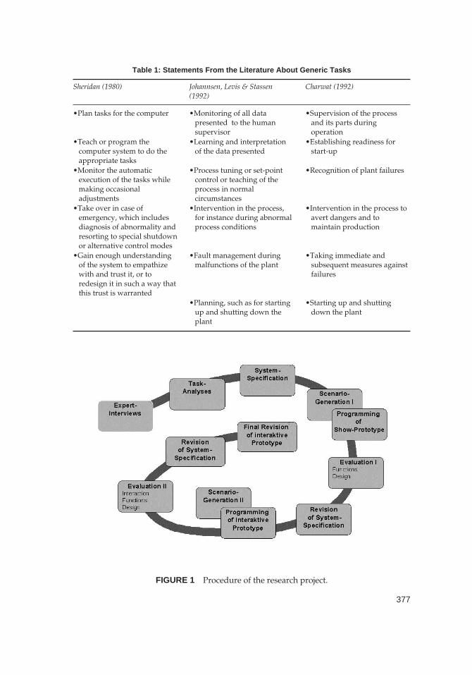
To standardize process control systems across sectors it is necessary to under-stand cross-sector core sequences. These are basic supervision and control actionsthat occur in all sectors. Matching building blocks shall be specified for these se-quences. Only a few references can be found in the literature (Table 1). This infor-mation is too abstract to allow requirements to be derived from it. It can also beargued that the introduction of higher degrees of automation and intelligent sup-port systems over recent years has altered the role and tasks of the operators in thecontrol rooms.
2. PROCEDURE
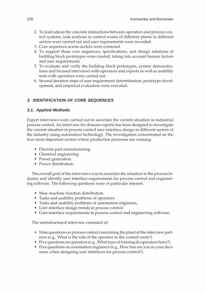
The following project plan was used (Figure 1):
1. To obtain domain knowledge about the context of use, expert interviewswere carried out in different sectors in which automated technical processesare running.
376 Komischke and Burmester
377
Table 1: Statements From the Literature About Generic Tasks
Sheridan (1980) Johannsen, Levis & Stassen(1992)
Charwat (1992)
•Plan tasks for the computer •Monitoring of all datapresented to the humansupervisor
•Supervision of the processand its parts duringoperation
•Teach or program thecomputer system to do theappropriate tasks
•Learning and interpretationof the data presented
•Establishing readiness forstart-up
•Monitor the automaticexecution of the tasks whilemaking occasionaladjustments
•Process tuning or set-pointcontrol or teaching of theprocess in normalcircumstances
•Recognition of plant failures
•Take over in case ofemergency, which includesdiagnosis of abnormality andresorting to special shutdownor alternative control modes
•Intervention in the process,for instance during abnormalprocess conditions
•Intervention in the process toavert dangers and tomaintain production
•Gain enough understandingof the system to empathizewith and trust it, or toredesign it in such a way thatthis trust is warranted
•Fault management duringmalfunctions of the plant
•Taking immediate andsubsequent measures againstfailures
•Planning, such as for startingup and shutting down theplant
•Starting up and shuttingdown the plant
FIGURE 1 Procedure of the research project.
2. To learn about the concrete interactions between operators and process con-trol systems, task analyses in control rooms of different plants in differentsectors were carried out and user requirements were recorded.
3. Core sequences across sectors were extracted.4. To support these core sequences, specifications, and design solutions of
building block prototypes were created, taking into account human factorsand user requirements.
5. To evaluate and verify the building block prototypes, system demonstra-tions and focused interviews with operators and experts as well as usabilitytests with operators were carried out.
6. Several iteration steps of user requirement determination, prototype devel-opment, and empirical evaluation were executed.
3. IDENTIFICATION OF CORE SEQUENCES
3.1. Applied Methods
Expert interviews were carried out to ascertain the current situation in industrialprocess control. An interview for domain experts has been designed to investigatethe current situation in process control user-interface design in different sectors ofthe industry using automation technology. The investigation concentrated on thefour most important sectors where production processes are running:
• Discrete part manufacturing.• Chemical engineering.• Power generation.• Power distribution.
The overall goal of the interviews was to ascertain the situation in the process in-dustry and identify user interface requirements for process control and engineer-ing software. The following questions were of particular interest:
• Man–machine function distribution.• Tasks and usability problems of operators.• Tasks and usability problems of automation engineers.• User-interface design trends in process control.• User-interface requirements in process control and engineering software.
The semistructured interview consisted of:
• Nine questions on process control concerning the plant of the interview part-ners (e.g., What is the role of the operator in the control room?)
• Five questions on operators (e.g., What type of training do operators have?)• Five questions on automation engineers (e.g., How free are you in your deci-
sions when designing user interfaces for process control?).
378 Komischke and Burmester
Nine expert interviews were carried out in leading companies situated in Ger-many. The interview partners were managers, sales persons, automation engi-neers, and software developers with an average professional experience of morethan 10 years in the domain of process control technology (see Color Plate 5, Figure2). Managers and salespersons had a good overview of the whole research issueand gave good information concerning future trends and industrial research anddevelopment activities related to plant management. Automation engineers andsoftware developers provided input on their own job and in particular their tasks,as well as the usability criteria and requirements in user-interface design. Theywere also able to give their views on the tasks of operators and could provide inputfor relevant scenarios, which have to be generated for field observations and us-ability tests on prototypes.
One question was central when investigating cross-sector building blocks: Theexperts were asked about the tasks and actions that operators carry out duringtheir shifts to supervise the technical process. Although only operators can give acomplete and detailed description of operators’ sequences, expert interviews pro-vide an effective way of gathering initial indications to help identify cross-sectorcore sequences.
The interviews were recorded on audiotape and transcribed afterward. Becauseexperts have little time, some of them had to cut their interviews short before an-swering all of the questions. Consequently the interviews had to be conducted withsufficient flexibility to allow the most important questions to be raised.
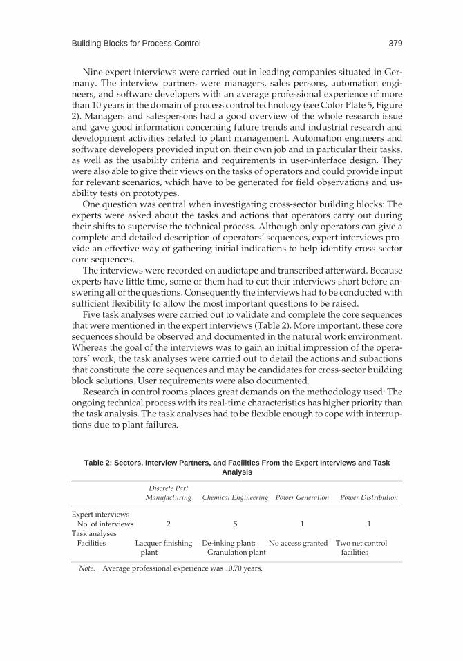
Five task analyses were carried out to validate and complete the core sequencesthat were mentioned in the expert interviews (Table 2). More important, these coresequences should be observed and documented in the natural work environment.Whereas the goal of the interviews was to gain an initial impression of the opera-tors’ work, the task analyses were carried out to detail the actions and subactionsthat constitute the core sequences and may be candidates for cross-sector buildingblock solutions. User requirements were also documented.
Research in control rooms places great demands on the methodology used: Theongoing technical process with its real-time characteristics has higher priority thanthe task analysis. The task analyses had to be flexible enough to cope with interrup-tions due to plant failures.
Building Blocks for Process Control 379
Table 2: Sectors, Interview Partners, and Facilities From the Expert Interviews and TaskAnalysis
Discrete PartManufacturing Chemical Engineering Power Generation Power Distribution
Expert interviewsNo. of interviews 2 5 1 1
Task analysesFacilities Lacquer finishing
plantDe-inking plant;
Granulation plantNo access granted Two net control
facilities
Note. Average professional experience was 10.70 years.
Second, as indicated in the literature, operators use different terminology fromsoftware ergonomists or developers and have difficulties in verbalizing manualor cognitive activities. They also rarely give concrete and detailed advice on fu-ture design, because they are mentally tied to their existing systems (Böhle &Rose, 1992).
The walk-through method (Christie, Scane, & Collyer, 1995) was therefore usedas a means of eliciting knowledge. This method helps to establish a rapport be-tween operator and researcher. The researcher accompanied the operator duringhis work and asked task-related questions (e.g., “Where is your first glance di-rected in this picture?”). The operator was also encouraged to think aloud and toexplain his interaction with the process control system. To avoid missing any of theimportant details or features on the monitors, the operator’s normal work was re-corded in sound and image on videotape. The videotapes were later analyzed indetail. Core sequences of each of the plants were identified and described in a re-port. The core sequences, which were found in all of the plants studied, weregrouped together and described using flowcharts and screen shots. Some of the in-teractions were detailed down to keystroke level.
3.2. Results
Cross-Sector Core Sequences
The interviews showed that different core sequences are performed in all of thesectors studied when interacting with process control systems.1
Navigating through the system. The large amount of data that is taken fromthe process is distributed and presented on different process mimics, which are hi-erarchically ordered. To gain an impression of the plant’s state, users have to navi-gate through overview mimics, area mimics, detail mimics, and graphs.
Analyzing pictures. Within one mimic, operators have special key points toexamine the current state of the process.
Recognizing and interpreting messages. Various messages with differentlevels of urgency are displayed on the operating system. The operator has to copewith urgent messages, such as alarms, quickly. Otherwise he or she risks a plantbreakdown, which is expensive.
380 Komischke and Burmester
1For further results of the expert interviews, refer to Burmester and Komischke (1999).
Communicating with maintenance. Control rooms are more or less isolatedfrom the process in terms of location. In most plants, operators do not leave theirroom to repair the damage. When malfunctions are registered maintenance staffhave to be sent to the right place quickly with a description of what is wrong.
Binary switching. To influence the process, the states of its units must be al-tered. Although there are basically three kinds of possible inputs (analog, binary,ASCII), only binary switching was mentioned in all sectors. Examples includeswitching motors on and off, and valves open or closed.
Results from analyzing the operators’ work show that the core sequences thatwere indicated in the expert interviews could indeed be found in the plants stud-ied. Interestingly enough, the walk-through method identified two more core se-quences that occur across sectors.
Graph interpretation. The display of the progression of data in time is impor-tant for both process optimization and for troubleshooting. For interpretation, thegraphs can be manipulated using several methods, for example scaling axes.
Updating logs. This core sequence could only be identified by analyzing vid-eotapes. The operators did not mention this activity nor did they perform it whilethe analyses took place. However, their log books could be seen on the videotapes.Many different logs are kept: production logs, failure logs, and so forth. Logs forhanding over the process to the next shift are kept in all sectors.
Requirements
Requirements were derived from operators’ suggestions for improvements andfrom the human factor specialists’ review of the situation in the plants. Two promi-nent examples are shown next.
Efficiency. Operators complained that the way in which important informa-tion about critical process conditions was gathered was inefficient. They requestedshorter navigation paths and clearer failure notifications. As operators in all plantsused communication devices like telephones, which were separate and independ-ent from the process control systems, integrating communication technologiesmight be beneficial. The same holds true for logs, which are generally kept in jotterpads. These two activities could be carried out more efficiently if they were inte-grated into the process control system, because operators would no longer have tolook away from their monitors that display the critical process information in thecase of failures and system data could be utilized for these activities via hyperlinksor other connections.
Building Blocks for Process Control 381
Manuals. No paper-based manuals were available in the control rooms in anyof the plants, and help provided by the process control system was insufficient. Theoperators run their technical processes from experience. They know what to dowhen failures that can not be handled by the automation system occur. Howeverthere are some types of failure that happen so rarely that the operators might nothave enough knowledge or proper training skills to cope with them. Some opera-tors complained that the texts that are displayed to explain the nature of a failurewere inaccurate and did not explain what measures to take to handle the failures.An integrated and intelligent help system could be beneficial. It should give de-tailed yet clear information about the nature of and reason for the failure and alsothe sequence of actions required. It should also provide the operator withhyperlinks to the relevant process pictures and service staff.
4. CONCEPTUAL SYSTEM DEVELOPMENT
4.1. Specifications for Building Blocks
Taking into account the solutions from the systems studied and new requirementsderived from the task analyses, specifications were drawn up for each of the poten-tial building blocks. These specifications were formulated in an abstract form. Thisavoided triggering or provoking the appearance of the design solutions. An exam-ple is: “When a telephone conversation is to be ended, the user is asked if he is surethat he wants to end the call.” The list of specifications was refined after each systemevaluation.
4.2. Noninteractive User-Interface Simulation
System Generation and Evaluation
The specified functions were implemented in a noninteractive prototype (seeColor Plate 5, Figure 2). Creating software solutions based on requirements in-volves considerable creativity, particularly when there are no style guides to fol-low. But ergonomic knowledge reduces the degree of freedom in the design.Standards can also be referred to, because they often show examples.
The intention was not to generate a prototype with the full functionality of theproposed building blocks, but to match a scenario. The basic situation described inthis scenario is a failure that occurs in the technical process. The operator has tocope with this critical incident by using the building blocks. Both scenario and pro-totype were specifically adapted to each sector.
The prototypes were programmed with Microsoft Power Point™ using VisualBasic for Applications™. Despite using a Microsoft™ tool it was decided not to usethe Microsoft Windows™ look and to give a sense of freedom in design decisions.The sector-specific versions differed only in the contents of their process picturesand labels. These mock-ups were basically slide shows, which simulated a graphi-
382 Komischke and Burmester
cal user interface of a process control system. Only the most important functionswere implemented and only one navigation path could be used to get through thescenario.
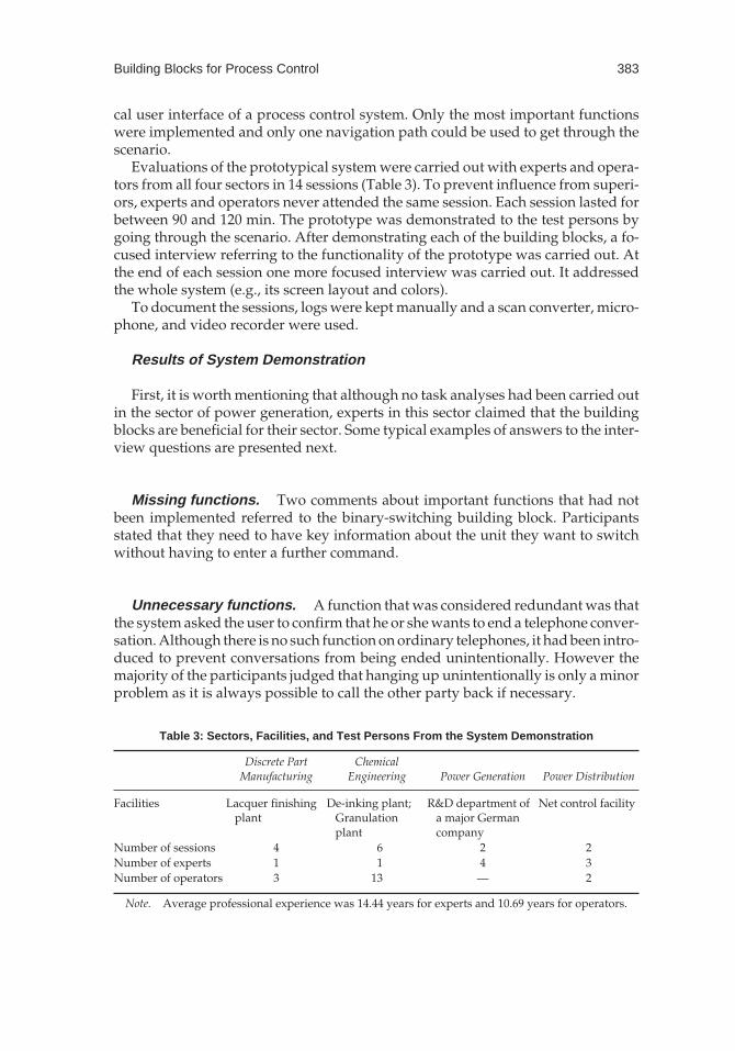
Evaluations of the prototypical system were carried out with experts and opera-tors from all four sectors in 14 sessions (Table 3). To prevent influence from superi-ors, experts and operators never attended the same session. Each session lasted forbetween 90 and 120 min. The prototype was demonstrated to the test persons bygoing through the scenario. After demonstrating each of the building blocks, a fo-cused interview referring to the functionality of the prototype was carried out. Atthe end of each session one more focused interview was carried out. It addressedthe whole system (e.g., its screen layout and colors).
To document the sessions, logs were kept manually and a scan converter, micro-phone, and video recorder were used.
Results of System Demonstration
First, it is worth mentioning that although no task analyses had been carried outin the sector of power generation, experts in this sector claimed that the buildingblocks are beneficial for their sector. Some typical examples of answers to the inter-view questions are presented next.
Missing functions. Two comments about important functions that had notbeen implemented referred to the binary-switching building block. Participantsstated that they need to have key information about the unit they want to switchwithout having to enter a further command.
Unnecessary functions. A function that was considered redundant was thatthe system asked the user to confirm that he or she wants to end a telephone conver-sation. Although there is no such function on ordinary telephones, it had been intro-duced to prevent conversations from being ended unintentionally. However themajority of the participants judged that hanging up unintentionally is only a minorproblem as it is always possible to call the other party back if necessary.
Building Blocks for Process Control 383
Table 3: Sectors, Facilities, and Test Persons From the System Demonstration
Discrete PartManufacturing
ChemicalEngineering Power Generation Power Distribution
Facilities Lacquer finishingplant
De-inking plant;Granulationplant
R&D department ofa major Germancompany
Net control facility
Number of sessions 4 6 2 2Number of experts 1 1 4 3Number of operators 3 13 — 2
Note. Average professional experience was 14.44 years for experts and 10.69 years for operators.
4.3. Interactive User-Interface Simulation
System Generation and Evaluation
The next iteration step was aimed at generating a prototype that could be tested forusability. This required an interactive prototype offering more than one possible pathto navigate through it. Because of this affordance and limitations in Visual Basic forApplications™ the next prototype was programmed with Microsoft Visual Basic™Version 5.0. The design was revised according to the comments of the first iteration.Most prominent were the new division of the screen and the use of new colors. Themiddlesectionwasenlargedandwaskept inshadesofgray; thehead-andfootlinebe-came smaller and were displayed in shades of blue (see Color Plate 5, Figure 3).
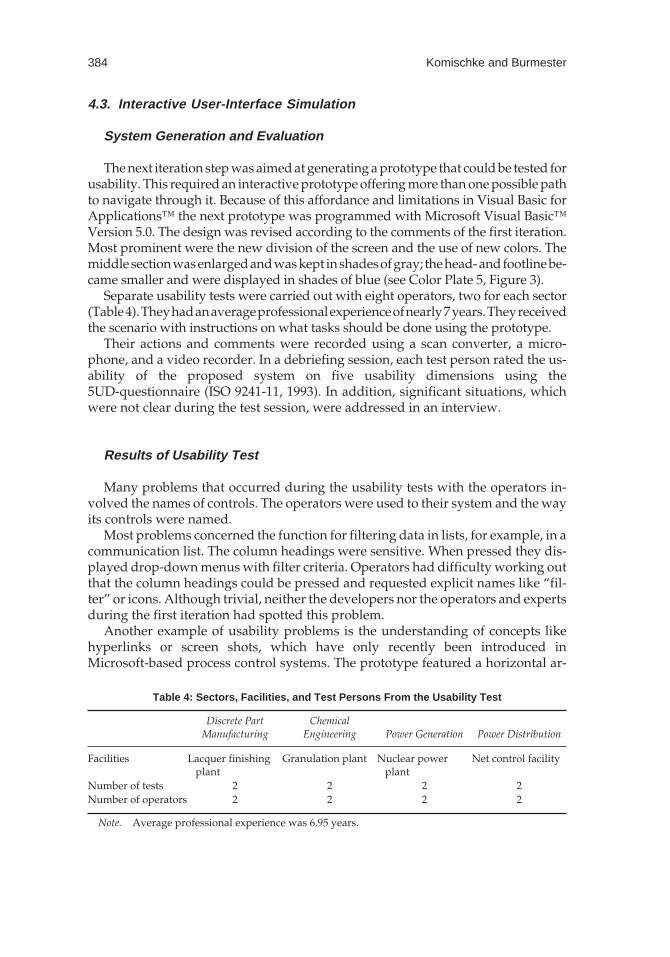
Separate usability tests were carried out with eight operators, two for each sector(Table4).Theyhadanaverageprofessionalexperienceofnearly7years.Theyreceivedthe scenario with instructions on what tasks should be done using the prototype.
Their actions and comments were recorded using a scan converter, a micro-phone, and a video recorder. In a debriefing session, each test person rated the us-ability of the proposed system on five usability dimensions using the5UD-questionnaire (ISO 9241-11, 1993). In addition, significant situations, whichwere not clear during the test session, were addressed in an interview.
Results of Usability Test
Many problems that occurred during the usability tests with the operators in-volved the names of controls. The operators were used to their system and the wayits controls were named.
Most problems concerned the function for filtering data in lists, for example, in acommunication list. The column headings were sensitive. When pressed they dis-played drop-down menus with filter criteria. Operators had difficulty working outthat the column headings could be pressed and requested explicit names like “fil-ter” or icons. Although trivial, neither the developers nor the operators and expertsduring the first iteration had spotted this problem.
Another example of usability problems is the understanding of concepts likehyperlinks or screen shots, which have only recently been introduced inMicrosoft-based process control systems. The prototype featured a horizontal ar-
384 Komischke and Burmester
Table 4: Sectors, Facilities, and Test Persons From the Usability Test
Discrete PartManufacturing
ChemicalEngineering Power Generation Power Distribution
Facilities Lacquer finishingplant
Granulation plant Nuclear powerplant
Net control facility
Number of tests 2 2 2 2Number of operators 2 2 2 2
Note. Average professional experience was 6.95 years.
row facing to the right as a hyperlink icon. Most of the operators interpreted thiswrongly. Although they felt that this could easily be learned, a new icon that dis-played a picture frame was chosen. ToolTips were also integrated.
The rating scales revealed that the efficiency of the prototype was judged good(6.3 on a scale from 1–9). Learnability and ease of use were even rated very good (8and 7.5 on a scale from 1–9). In the interviews after each usability test session theoperators rated the prototype as better than their existing process control systemsin terms of efficiency and ease of use. They indicated that the proposed systemshould be expanded with the functionality required to supervise the individualtechnical processes. It is obvious that cross-sector building blocks alone cannot re-place the process control system of a specific plant with all the specific tasks the op-erators have to perform to supervise and control it.
5. DISCUSSION OF BENEFITS AND FUTURE WORK
5.1. The Proposed Building Blocks
Operators in all facilities studied were of the opinion that the proposed user inter-face with its building blocks is an improvement compared to the existing systems.Product managers are also interested in the results of our research. During informalpresentations and discussions automation engineers stated that the building blocksare “exactly what we need.” In particular, the integration of communication andlogs for handing over the process to the next shifts were regarded as groundbreak-ing. They confirmed the potential of the building blocks to reduce design time andsuggested widening the search for core sequences to sequences that occur in severalsectors. The preferred option is analog input, which is prominent in chemical engi-neering and power generation. To identify more core sequences, task analyses inthe field have to be carried out.
5.2. Potential of Building Blocks to Be Appliedin Nonindustrial Processes
The proposed building blocks are believed to have the potential for application inother sectors or processes such as traffic control, as these domains show similar char-acteristics regarding the structure of data and the demands on human supervisors.The example of power generation showed that this sector can profit from the pro-posed cross-sector building blocks, even though no task analyses were performed inthis sector. To examine whether other different sectors such as traffic control can alsoprofit from these modules, interviews and task analyses have to be carried out.
REFERENCES
Aguirre, C., de Pablo, E., Zaccagnini, J. L., & Alaman, X. (1992). The user interface in expertsystems for real-time process control: The MIP system experience. IFIP Transactions A(Computer Science and Technology), A-14, 266–272.
Building Blocks for Process Control 385
Böhle, F., & Rose, H. (1992). Technik und Erfahrung: Arbeit in hochautomatisierten Systemen[Technology and experience: Work in highly automated systems]. Frankfurt/Main, Ger-many: Campus Verlag.
Burmester, M., & Komischke, T. (1999). Nutzeranforderungen als Grundlage für dieEntwicklung innovativer user interfaces in der industriellen Prozeßführung [User re-quirements as a basis for the development of innovative user interfaces in industrial pro-cess control]. In U. Arend, E. Eberleh, & K. Pitschke (Eds.), Software-ergonomie ’99: Designvon Informationswelten (pp. 53–62). Stuttgart, Germany: Teubner.
Charwat, H. J. (1992). Lexikon der Mensch-Maschine-Kommunikation [Lexicon of man–machinecommunication]. Munich, Germany: Oldenbourg Verlag.
Christie, B., Scane, R., & Collyer, J. (1995). Evaluation of human–computer interaction at theuser interface to advanced IT systems. In J. R. Wilson & E. N. Corlett (Eds.), Evaluation ofhuman work (2nd ed., pp. 310–356). London: Taylor & Francis.
International Standards Organization 9241-11. (1993). Ergonomische Anforderungen fürBürotätigkeiten mit Bildschirmgeräten: Anforderungen an die Gebrauchstauglichkeit - Leitsätze[Ergonomic requirements for office work with visual display terminals: Guidance onusability]. Berlin: Beuth Verlag.
Johannsen, G., Levis, A. H., & Stassen, H. G. (1992). Theoretical problems in man–machinesystems and their experimental validation. In H. G. Stassen (Ed.), Analysis, design and eval-uation of man–machine systems 1992 (pp. 19–29). Oxford, England: Pergamon.
Kolski, C. (1993). Formalization approaches of ergonomic knowledge for “intelligent” de-sign, evaluation and management of man–machine interface in process control. In A.Ollero & E. F. Camacho (Eds.), Intelligent components and instruments for control applications:Selected papers from the IFAC symposium (pp. 175–180). Oxford, England: Pergamon.
Sheridan, T. B. (1980). Computer control and human alienation. Technology Review, MIT,60–76.
Vale, Z. A., Faria, L., Ramos, C., Fernandez, M. F., & Marques, A. (1996). Towards more intel-ligent and adaptive user interfaces for control center applications. In O. A. Mohammed &K. Tomsovic (Eds.), ISAP 96: International conference on intelligent systems applications topower systems proceedings (pp. 2–6). New York: IEEE.
386 Komischke and Burmester
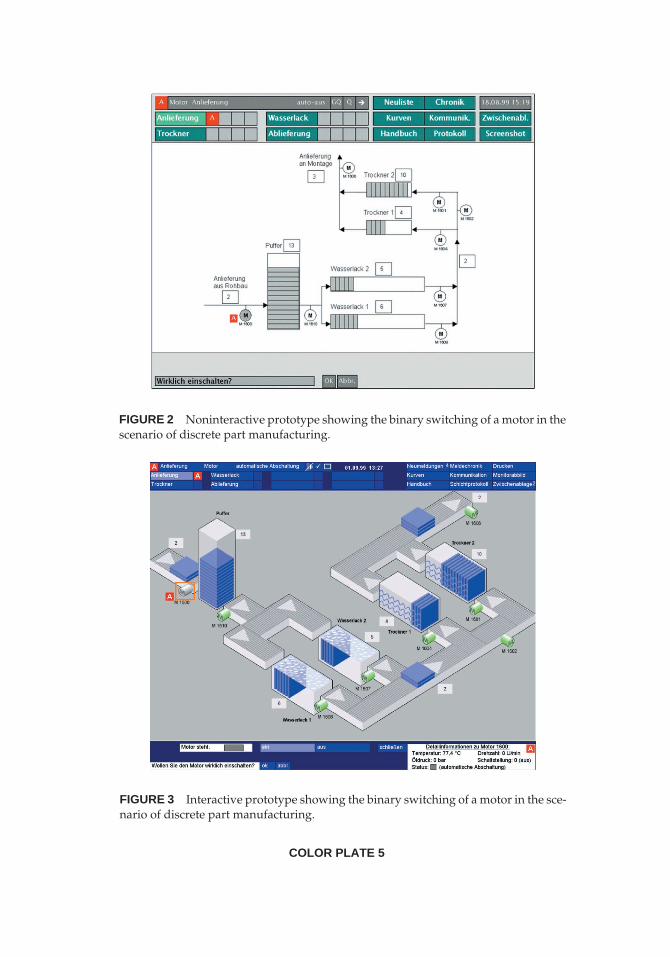
FIGURE 2 Noninteractive prototype showing the binary switching of a motor in thescenario of discrete part manufacturing.
FIGURE 3 Interactive prototype showing the binary switching of a motor in the sce-nario of discrete part manufacturing.
COLOR PLATE 5