us00000010054777b220180821 - ntrs.nasa.gov ·...
TRANSCRIPT
1111111111111111111111111111111111111111111111111111111111111111111111
(12) United States PatentWallace et al.
(54) COMMON-MODE DIGITAL HOLOGRAPHICMICROSCOPE
(71) Applicant: California Institute of Technology,Pasadena, CA (US)
(72) Inventors: James K. Wallace, Pasadena, CA (US);Kurt M. Liewer, Pasadena, CA (US);Christian A. Lindensmith, Altadena,CA (US); Eugene Serabyn, Claremont,CA (US); Stephanie Rider, Monrovia,CA (US); Emilio C. Graff, Burlingame,CA (US)
(73) Assignee: California Institute of Technology,Pasadena, CA (US)
(*) Notice: Subject to any disclaimer, the term of thispatent is extended or adjusted under 35U.S.C. 154(b) by 0 days.
(21) Appl. No.: 14/939,389
(22) Filed: Nov. 12, 2015
(65) Prior Publication Data
US 2016/0131882 Al May 12, 2016
Related U.S. Application Data
(60) Provisional application No. 62/078,288, filed on Nov.11, 2014, provisional application No. 62/079,342,filed on Nov. 13, 2014.
(51) Int. Cl.G02B 21/00 (2006.01)G03H 1/04 (2006.01)G02B 21/18 (2006.01)G03H 1/00 (2006.01)
(52) U.S. Cl.CPC ....... G02B 21/0056 (2013.01); G02B 21/008
(2013.01); G02B 21/0008 (2013.01);
(Continued)
(io) Patent No.: US 10,054,777 B2(45) Date of Patent: Aug. 21, 2018
(58) Field of Classification SearchCPC ................ G02B 21/0056; G02B 21/18; G02B
21/0072; G02B 21/0008; G02B 21/008;
(Continued)
(56) References Cited
U.S. PATENT DOCUMENTS
3,580,655 A * 5/1971 Leith ...................... GOIB 9/021355/2
3,756,683 A * 9/1973 Smith, Jr . ................ G03H 1/08359/29
(Continued)
FOREIGN PATENT DOCUMENTS
WO WO 2007108060 Al * 9/2007 ......... GO1B 11/2441
OTHER PUBLICATIONS
"Optics and Lasers An engineering Physics approach" to M.Young, Springer Verlag Ed. 1977 (p. 118).*
(Continued)
Primary Examiner Mohamed K Amara
(74) Attorney, Agent, or Firm Gates & Cooper LLP
(57) ABSTRACT
A lens-less digital holographic microscope, a reflectivedigital holographic microscope, and a digital holographicmicroscope including a plurality of lenses. In one example,the digital holographic microscope includes a single modefiber collimated light source which provides illumination forboth the ̀ science' and ̀reference' arms, a pair of microscopeobjectives located side-by side, and illuminated by thecommon beam, a relay lens whose center is between the twoobjectives, and a focal plane element where the interferencepattern is measured.
.L ..fi... ,....r'4
21 Claims, 13 Drawing Sheets
https://ntrs.nasa.gov/search.jsp?R=20180005307 2018-11-29T15:46:12+00:00Z
US 10,054,777 B2Page 2
(52) U.S. Cl.CPC ......... G02B 21/0072 (2013.01); G02B 21/18
(2013.01); G03H 1/0443 (2013.01); G03H20011005 (2013.01); G03H 200110445
(2013.01); G03H 2222112 (2013.01); G03H2222113(2013.01); G03H 2227102 (2013.01)
(58) Field of Classification SearchCPC ............. G03H 1/0443; G03H 2227/02; G03H
2001/005; G03H 2001/0445; G03H2222/12; G03H 2222/13; GO1B 11/2441;
GO1B 9/02057; GO1B 9/0209USPC ................. 356/521, 511, 512, 515, 520, 450See application file for complete search history.
(56) References Cited
U.S.PATENT DOCUMENTS
6,549,285 B1 * 4/2003 Wright ............... GO IN 21/1717356/497
6,879,427 B2 * 4/2005 Mendlovic ............. G02B 26/06356/520
7,023,563 B2 * 4/2006 Li ........................ A61B 5/0059356/521
7,349,102 B2 * 3/2008 Shirley .................... GO1D 5/38356/512
7,791,023 B2 * 9/2010 Kasai ....................... G03H 5/00250/311
7,816,648 B2* 10/2010 Harada ................... HO1J37/26250/306
7,872,755 B2* 1/2011 Harada ................. HOIJ37/295356/450
8,785,851 B2 * 7/2014 Tanigaki ............... HO1J 37/295250/306
9,316,536 B2 * 4/2016 Takesue .................... GO1J 1/449,678,476 B2 * 6/2017 Smithwick ........... G03H 1/2294
2003/0160969 Al* 8/2003 Endo .................. GO1B 11/2441356/520
2004/0156098 Al* 8/2004 Dubois .............. GO1N 21/6458359/368
2008/0137933 Al* 6/2008 Kim ....................... GO1B 9/021382/131
2009/0046298 Al* 2/2009 Betzig ................ GO IN 21/6445356/521
2009/0296558 Al * 12/2009 Akahoshi ............. GLIB 7/0065369/103
2010/0110260 Al* 5/2010 Shin ..................... G03H 1/0866348/311
2010/0253986 Al* 10/2010 Awatsuji .............. G03H 1/0443359/10
2010/0271676 Al * 10/2010 Renaud-Goud .......... G03H 1/22359/9
2010/0309465 Al* 12/2010 Liu ........................... GO1J3A4356/301
2012/0200901 Al* 8/2012 Dubois .................. G02B 21/00359/15
2013/0088568 Al* 4/2013 Nolte ................... A61B 5/0075348AO
2013/0293697 Al* 11/2013 Sun ...................... G02B 21/361348/79
2014/0375792 Al* 12/2014 Yaqoob .................. G02B 21/14348/79
2015/0205260 Al* 7/2015 Awatsuji .............. G03H 1/0866348AO
2017/0003650 Al* 1/2017 Moser .................. G03H 1/044320 17/0 13 1682 Al* 5/2017 Nolte ................... G03H 1/0443
OTHER PUBLICATIONS
https:Hen.wikipedia.org/wiki/Angular resolution.*https:Hen.wikipedia.org/wiki/Fraunhofer diffraction. *Knox, C., "Holographic microscopy as a technique for recordingdynamic microscopic subjects," Science 153(3739), 989-990(1966).
Chengala, A. et al., "Microalga propels along vorticity direction ina shear flow," Phys. Rev. E, 87, 052704 (2013).Sheng, J. et al., "Digital holographic microscopy reveals prey-induced changes in swimming behavior of predatory dinoflagel-lates," PNAS 104(44), 17512-17517 (2007).Sheng, J., "A dinoflagellate exploits toxins to immobilize prey priorto ingestion," PNAS 107(5), 2082-2087 (2010).Vater, S. M. et al., "Holographic microscopy provides new insightsinto the settlement of zoospores of the green alga Ulva lima oncationic oligopeptide surfaces," Biofouling 31(2), 229-239 (2015).Pavillon, N. et al. "Early cell death detection with digital holo-graphic microscopy," PLoS ONE 7, e0030912 (2012).Marquet, P. et al., "Digital holographic microscopy: a noninvasivecontrast imaging technique allowing quantitative visualization ofliving cells with subwavelength axial accuracy," Optics letters30(5), 468-470 (2005).Kemper, B. et al., "Investigation of living pancreas tumor cells bydigital holographic microscopy," Journal of biomedical optics 11,034005 (2006).Jourdain, P. et al., "Determination of transmembrane water fluxes inneurons elicited by glutamate ionotropic receptors and by thecotransporters KCC2 and NKCCL a digital holographic micros-copy study," The Journal of Neuroscience 31(33), 11846-11854(2011).Janeckova, H. et al., "Proving tumour cells by acute nutritional/energy deprivation as a survival threat: a task for microscopy,"Anticancer research 29(6), 2339-2345 (2009).Miniotis, M. et al., "Digital holographic microscopy for non-invasive monitoring of cell cycle arrest in L929 cells," PLoS one 9,el06546 (2014).Su, T.-W. et al., "High-throughput lensfree 3D tracking of humansperms reveals rare statistics ofhelical trajectories," PNAS 109(40),16018-16022 (2012).Fenchel, T. "Microbial behavior in a heterogeneous world," Science296(5570), 1068-1071 (2002).Fenchel, T. "Eppur si muove: many water column bacteria aremotile," Aquatic Microbial Ecology 24(2), 197-201 (2001).Mitchell, J. G. et al., "Bacterial motility: links to the environmentand a driving force for microbial physics," FEMS microbiologyecology 55(1), 3-16 (2006).Purcell, E. M., "Life at low Reynolds number," Am. J. Phys. 45(1),3-11 (1977).Rivera, M. J. et al., "Unraveling the three-dimensional morphologyof archean microbialites," Journal of Paleontology 88(4), 719-726(2014).Schnars, U. et al., "Direct Recording of Holograms by a CCD Targetand Numerical Reconstruction," Applied optics 33(2), 179-181(1994).Schnars, U. et al., "Digital recording and numerical reconstructionof holograms," Measurement science and technology 13(9), R85-R101 (2002).Cuche, E. et al., "Simultaneous amplitude-contrast and quantitativephase-contrast microscopy by numerical reconstruction of Fresneloff-axis holograms," Applied optics 38(34), 6994-7001 (1999).Cuche, E. et al., "Spatial filtering for zero-order and twin-imageelimination in digital off-axis holography," Applied optics 39(23),4070-4075 (2000).Mann, C. et al., "High-resolution quantitative phase-contrastmicroscopy by digital holography," Optics Express 13(22), 8693-8698 (2005).Zhang, F. et al., "Reconstruction algorithm for high-numerical-aperture holograms with diffraction-limited resolution," Optics let-ters 31(11), 1633-1635 (2006).Colomb, T. et al., "Automatic procedure for aberration compensa-tion in digital holographic microscopy and applications to specimenshape compensation," Applied optics 45(5), 851-863 (2006).Xu, W. et al., "Digital in-line holography for biological applica-tions," PNAS 98(20), 11301-11305 (2001).Molaei, M. et al., "Imaging bacterial 3D motion using digital in-lineholographic microscopy and correlation-based de-noising algo-rithm," Optics Express 22(26), 32119-32137 (2014).Yamaguchi, I. et al., "Phase-shifting digital holography," Opticsletters 22(16), 1268-1270 (1997).

US 10,054,777 B2Page 3
(56) References Cited
OTHER PUBLICATIONS
Jericho, S.K. et al., "In-line digital holographic microscopy forterrestrial and exobiological research," Planetary and Space Science58, 701-705 (2010).Kuhn, J. et al., "A Mach-Zehnder digital holographic microscopewith sub-micrometer resolution for imaging and tracking of marinemicro-organisms," Review of Scientific Instruments 85(12) (2014).Junge, K. et al., "Motility of colwellia psychrerythraea strain 34Hat subzero temperatures," Appl Environ Microbiol 69(7), 4282-4284 (2003).Gong, Y. et al., "Image enhancement by gradient distributionspecification," Proc. ACCV, 12th Asian Conference on ComputerVision Workshop on Emerging Topics in Image Enhancement andRestoration, w7-p3 (2014).
* cited by examiner
U.S. Patent Aug. 21, 2018 Sheet 1 of 13 US 10,054,777 B2
l
v fir:: 3%'.
ig~ 1(q Fig. 1(b) Fig. 1(t)
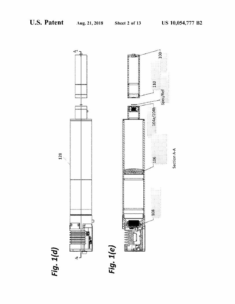
Fig. 1(d)
128
----------
---------
......
......
......
-
. ,,.
......
......
......
......
......
......
......
... .
.
Fig. 1(e)
Sect
ion A-A
i
U.S. Patent Aug. 21, 2018 Sheet 3 of 13 US 10,054,777 B2
U.S. Patent Aug. 21, 2018 Sheet 4 of 13 US 10,054,777 B2
Fig. 2(a) Fig. 2(b)
Fig. 2(c) Fig. 2(d)
U.S. Patent Aug. 21, 2018 Sheet 5 of 13 US 10,054,777 B2
Fig. 3(d) Fig. 3(e) Fig. 3(f)
U.S. Patent Aug. 21, 2018 Sheet 6 of 13
Fig. 4(a)
Fig. 4(b)
US 10,054,777 B2
402
U.S. Patent Aug. 21, 2018 Sheet 7 of 13 US 10,054,777 B2
500
Positioning Coherent Source
Positioning Collimator
504
Positioning Sample Mount
506
Positioning Microscope Assembly
I
Positioning Detector
510
Connecting Computer(s)
Fig. 5
U.S. Patent
602
610
Aug. 21, 2018 Sheet 8 of 13 US 10,054,777 B2
Fig. 6
Z1
600
604
U.S. Patent Aug. 21, 2018 Sheet 9 of 13 US 10,054,777 B2
700
Providing first waveguide
-------------------------------------------------------------------------------------------------------------------
Providing second waveguide
704
Providing camera
706
Connecting Computer
Fig. 7
U.S. Patent
800
0
0:I.
Aug. 21, 2018 Sheet 10 of 13 US 10,054,777 B2
802
S 804
Fig. 8a
U.S. Patent Aug. 21, 2018 Sheet 11 of 13 US 10,054,777 B2
818
816<
825
Sample
x
y
Imaging Array 832
Reflective Objective 824 828
Fig. Sb
822
830Reflective Relay OAP
U.S. Patent Aug. 21, 2018 Sheet 12 of 13
- 902
904A - 9048
GENERAL PURPOSE SPECIAL PURPOSEPROCESSOR PROCESSOR
MEMORY908 910
- 922 916
Fig. 9
--914
US 10,054,777 B2
DATABASE
1016
Fig. 10
i
US 10,054,777 B2
COMMON-MODE DIGITAL HOLOGRAPHICMICROSCOPE
CROSS REFERENCE TO RELATEDAPPLICATIONS
This application claims the benefit under 35 U.S.C. Sec-tion 119(e) of the following commonly-assigned U.S. Pro-visional Patent Applications:
U.S. Provisional Patent Application Ser. No. 62/078,288,filed on Nov. 11, 2014, by Kurt M. Liewer, Christian A.Lindensmith, Eugene Serabyn, Stephanie Rider, Emilio C.Graff, and James K. Wallace, entitled "A COMMON-MODE DIGITAL HOLOGRAPHIC MICROSCOPE,"; and
U.S. Provisional Patent Application Ser. No. 62/079,342,filed on Nov. 13, 2014, by Kurt M. Liewer, Christian A.Lindensmith, Eugene Serabyn, Stephanie Rider, Emilio C.Graff, and James K. Wallace, entitled "A COMMON-MODE DIGITAL HOLOGRAPHIC MICROSCOPE,";
which applications are incorporated by reference herein.
STATEMENT REGARDING FEDERALLYSPONSORED RESEARCH AND
DEVELOPMENT
The invention described herein was made in the perfor-mance of work under a NASA contract, and is subject to theprovisions of Public Law 96-517 (35 USC 202) in which theContractor has elected to retain title.
BACKGROUND OF THE INVENTION
1. Field of the InventionThis invention relates to a digital microscope.2. Description of the Related Art(Note: This application references a number of different
publications as indicated throughout the specification by oneor more reference numbers within brackets, e.g., [x]. A listof these different publications ordered according to thesereference numbers can be found below in the section entitled"References." Each of these publications is incorporated byreference herein.)
Bacterial motility plays a role in critical environmentaland physiological processes, including nutrient cycling, bio-fouling, and virulence. Despite its importance, motility hasonly been studied in a few test organisms because of thedifficulties of imaging moving micrometer-sized cells. How-ever, the study of the motility of microorganisms is a fieldwhich promises to be revolutionized by digital holographicmicroscopy (DHM) [1]. Because this imaging techniqueinstantaneously probes a large sample volume (milliliters) inthree dimensions, it enables the reconstruction of swimmingtrajectories of essentially unconstrained cells. The feasibilityof this approach has been demonstrated in the open ocean formeasurements of the distribution and swimming patterns ofplankton [2], and investigation of dinofiagellate feedingbehavior [3,4]. It has also been used in the laboratory tostudy motility of algal zoospores [5] and cultured cells[6-12]. However, because of the technical limitations ofexisting fieldable DHM instruments, such field experimentshave so far been restricted to eukaryotic cells>10 µm indiameter. In order to capture bacterial motility, real-timeimaging with spatial resolution of <1 µm in all dimensionsis required. Such an instrument would allow for in situinvestigations of bacterial motility in bodies of water, which
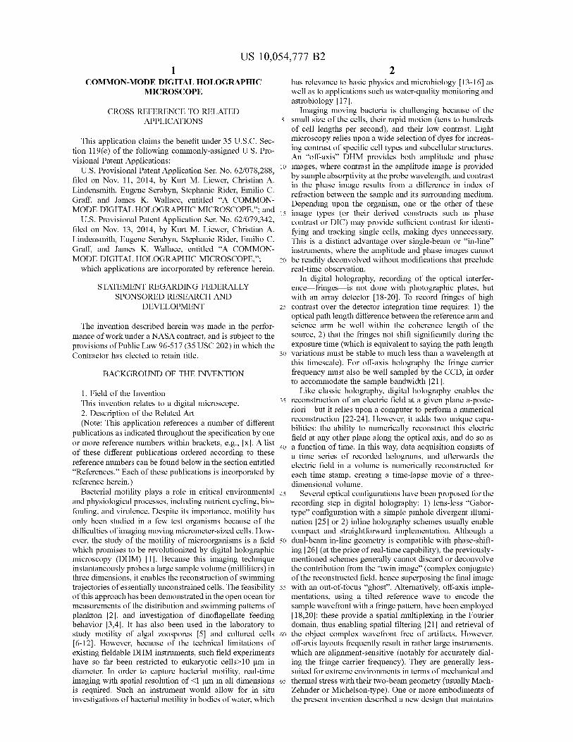
2has relevance to basic physics and microbiology [13-16] aswell as to applications such as water-quality monitoring andastrobiology [17].Imaging moving bacteria is challenging because of the
5 small size of the cells, their rapid motion (tens to hundredsof cell lengths per second), and their low contrast. Lightmicroscopy relies upon a wide selection of dyes for increas-ing contrast of specific cell types and subcellular structures.An "off-axis" DHM provides both amplitude and phase
io images, where contrast in the amplitude image is providedby sample absorptivity at the probe wavelength, and contrastin the phase image results from a difference in index ofrefraction between the sample and its surrounding medium.Depending upon the organism, one or the other of these
15 image types (or their derived constructs such as phasecontrast or DIC) may provide sufficient contrast for identi-fying and tracking single cells, making dyes unnecessary.This is a distinct advantage over single-beam or "in-line"instruments, where the amplitude and phase images cannot
20 be readily deconvolved without modifications that precludereal-time observation.
In digital holography, recording of the optical interfer-ence---fringes-4s not done with photographic plates, butwith an array detector [18-20]. To record fringes of high
25 contrast over the detector integration time requires: 1) theoptical path length difference between the reference arm andscience arm be well within the coherence length of thesource, 2) that the fringes not shift significantly during theexposure time (which is equivalent to saying the path length
30 variations must be stable to much less than a wavelength atthis timescale). For off-axis holography the fringe carrierfrequency must also be well sampled by the CCD, in orderto accommodate the sample bandwidth [21].
Like classic holography, digital holography enables the35 reconstruction of an electric field at a given plane a-poste-
riori but it relies upon a computer to perform a numericalreconstruction [22-24]. However, it adds two unique capa-bilities: the ability to numerically reconstruct this electricfield at any other plane along the optical axis, and do so as
4o a function of time. In this way, data acquisition consists ofa time series of recorded holograms, and afterwards theelectric field in a volume is numerically reconstructed foreach time stamp, creating a time-lapse movie of a three-dimensional volume.
45 Several optical configurations have been proposed for therecording step in digital holography: 1) lens-less "Gabor-type" configuration with a simple pinhole divergent illumi-nation [25] or 2) inline holography schemes usually enablecompact and straightforward implementation. Although a
5o dual-beam in-line geometry is compatible with phase-shift-ing [26] (at the price of real-time capability), the previously-mentioned schemes generally cannot discard or deconvolvethe contribution from the "twin image" (complex conjugate)of the reconstructed field, hence superposing the final image
55 with an out-of-focus "ghost'. Alternatively, off-axis imple-mentations, using a tilted reference wave to encode thesample wavefront with a fringe pattern, have been employed[18,20]: these provide a spatial multiplexing in the Fourierdomain, thus enabling spatial filtering [21] and retrieval of
60 the object complex wavefront free of artifacts. However,off-axis layouts frequently result in rather large instruments,which are alignment-sensitive (notably for accurately dial-ing the fringe carrier frequency). They are generally less-suited for extreme environments in terms of mechanical and
65 thermal stress with their two-beam geometry (usually Mach-Zehnder or Michelson-type). One or more embodiments ofthe present invention described a new design that maintains
US 10,054,777 B2
3the off-axis implementation, but with a robust optical designwhich maintains performance.
SUMMARY OF THE INVENTION
One or more embodiments of the invention disclose animaging system (e.g., an off-axis digital holographic micro-scope), comprising at least one coherent electromagneticradiation source emitting electromagnetic radiation; a colli-mator positioned to collimate the electromagnetic radiation ioand form collimated electromagnetic radiation; a samplemount; and a microscope assembly.The sample mount is positioned such that a sample
mounted on the sample mount interacts with the collimatedelectromagnetic radiation to form sample electromagnetic 15radiation, and one or more references mounted on thesample mount interact with the collimated electromagneticradiation to form reference electromagnetic radiation.The microscope lens assembly, comprising a first lens, a
second lens, and a relay lens, can be positioned such that: 20
at least a portion of the sample electromagnetic radiationis transmitted through the first lens, and then the relaylens, to a detector,
at least a portion of the reference electromagnetic radia-tion is transmitted through the second lens, and then the 25relay lens, to the detector,
the portion of the sample electromagnetic radiation andthe portion of the reference electromagnetic radiationare directed by the relay lens onto the detector at anangle with respect to each other so as to form an 30interference pattern on the detector, and
one or more computers can numerically/digitally con-struct/compute an image of the sample from the inter-ference pattern detected by the detector. The one ormore computers can compute an amplitude and/or 35phase of one or more electric fields at the sample.
The microscope assembly can comprise a reflective objec-tive and a relay mirror, positioned such that:
at least a portion of the sample electromagnetic radiationand the reflected electromagnetic radiation are reflected 40from the reflective objective, and then the relay mirror,to an imaging array,
the portion of the sample electromagnetic radiation andthe portion of the reference electromagnetic radiationare directed by the relay mirror onto the imaging array 45so as to form an interference pattern on the imagingarray, and
one or more computers can numerically/digitally con-struct/compute an image of the sample from the inter-ference pattern detected by the imaging array. 50
The electromagnetic radiation can comprise a single ormultiple (fixed or scanned) wavelengths. The sample mountcan comprise a sample window transmitting the multiplewavelengths to the sample, and a plurality of referencewindows, each of the reference windows transmitting a 55different one of the wavelengths to one of the plurality of thereferences.The imaging system can have a transmission geometry
such that the first lens and the second lens collect at leastsome of the sample electromagnetic radiation transmitted 60through the sample.The imaging system can have a reflection geometry such
that the first lens and the second lens collect at least some ofthe sample electromagnetic radiation reflected by thesample. 65
The sample can comprise one or more biological cells ina liquid and the reference can comprise the liquid.
_►,
The image can have a resolution of less than 1 micrometerover a 0.4 mmx0.4 mmx0.4 mm volume of the sample.
Positions of the collimator, the sample mount, the sample,the references, the first lens, the second lens, and the relaylens can be such that a resolution of the image does notchange when a temperature, of an environment in physicalcontact the imaging system, is reduced from 20° C. to —26°C., without adjustment of the positions.The imaging system can be portable to, and operational
in, a marine environment or an arctic environment in physi-cal contact with the imaging system, without adjustment ofpositions of the collimator, the mount, the first lens, thesecond lens, and the relay lens.The sample mount, the first lens, and the second lens can
be positioned such that the portion of the sample electro-magnetic radiation comprises a first straight line trajectoryfrom the sample to the relay lens and passing through acenter of the first lens, the portion of the reference electro-magnetic radiation comprises a second straight line trajec-tory from the sample to the relay lens and passing througha center of the second lens, and the first straight linetrajectory and the second straight line trajectory are parallel.A sample window can be placed in front of the sample to
define the area of the sample irradiated by the collimatedelectromagnetic radiation. A reference window can beplaced in front of each of the references to define the area ofeach of the references irradiated by the collimated electro-magnetic radiation.The first lens can be positioned at a distance f from the
sample, wherein f is a focal distance of the first lens. Thesecond lens (identical to the first lens) can be positioned atthe distance f from the reference.The components of the imaging system can be fixed such
that:an optical path length, from a center of the samplewindow to a center of the detector, can be identical toeach optical path length from each center of eachreference window to the center of the detector, and
an optical path length from an output of the source to thecenter of the sample window can be identical to eachoptical path length from the output to each center ofeach reference window.
The first lens and second lens can be co-mounted on a lensmount such that both the first lens and the second lens movetogether as a unit under thermal bending. The components ofthe imaging system can be positioned such that lateralthermal motion of the sample and/or relay lens relative to theremainder of the imaging system only laterally shifts thefringe pattern on the detector and does not affect the image.The imaging system allows fabrication of a microscope
without a beamsplitter or mirror, wherein the sample and thereference are irradiated by a single, common, and unsplitregion of the collimated beam.One or more embodiments of the invention further dis-
close a lens-less imaging system. The lens-less systemcomprises a first single mode waveguide guiding first coher-ent electromagnetic radiation onto a sample, wherein thesample transmits the first coherent electromagnetic radiationto form sample electromagnetic radiation. The lens-lesssystem further comprises a second single mode waveguidefixed at an angle with respect to the first single modewaveguide, the second single mode waveguide guidingsecond coherent electromagnetic radiation onto a reference,and the reference transmitting the second coherent electro-magnetic radiation to form reference electromagnetic radia-tion. The lens-less system further comprises a camera posi-tioned to detect an interference pattern formed by the
US 10,054,777 B2
5reference electromagnetic radiation and the sample electro-magnetic radiation interfering on the camera.
BRIEF DESCRIPTION OF THE DRAWINGS
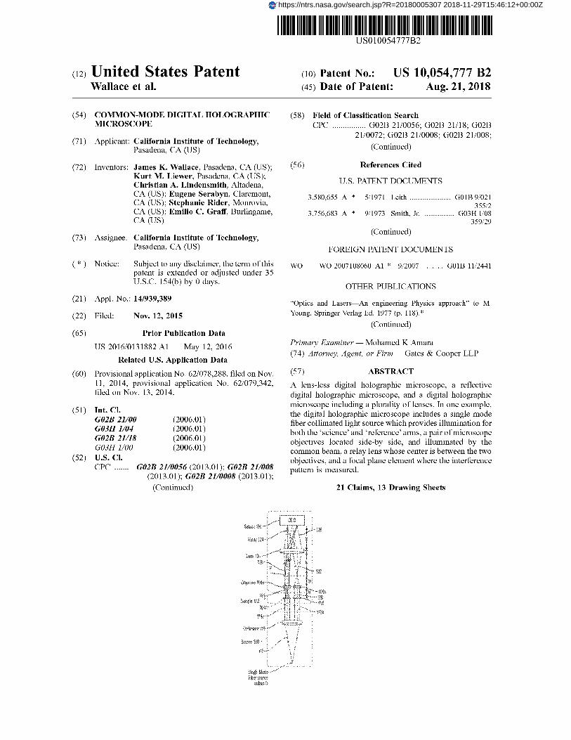
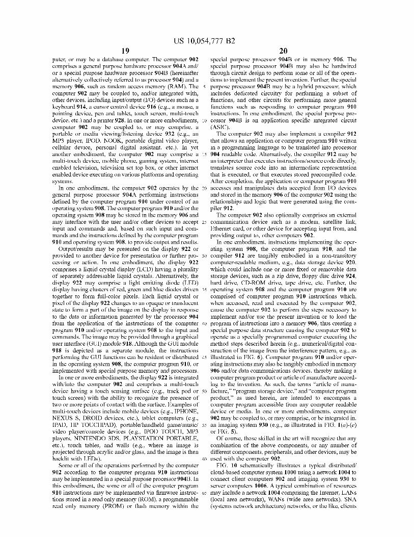
Referring now to the drawings in which like referencenumbers represent corresponding parts throughout:FIGS. 1(a)-(e) are schematics and images of the compact,
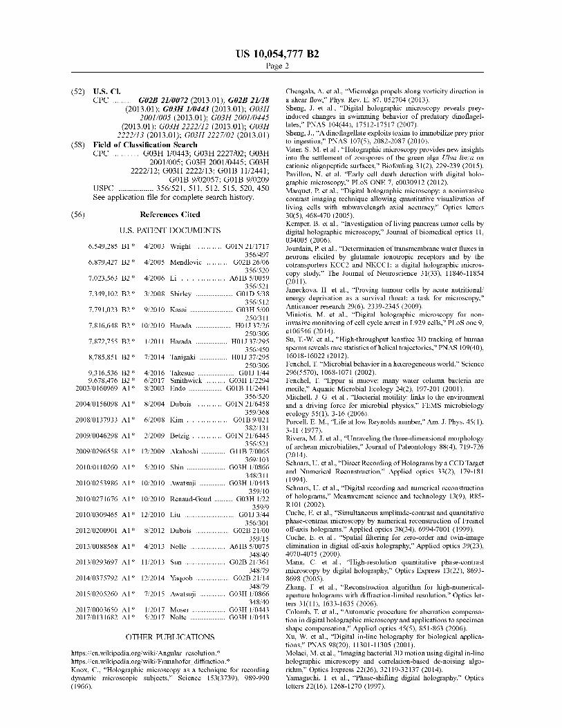
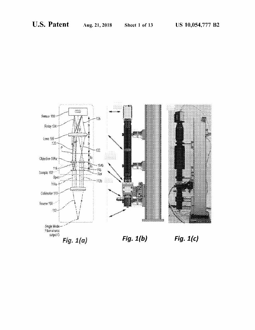
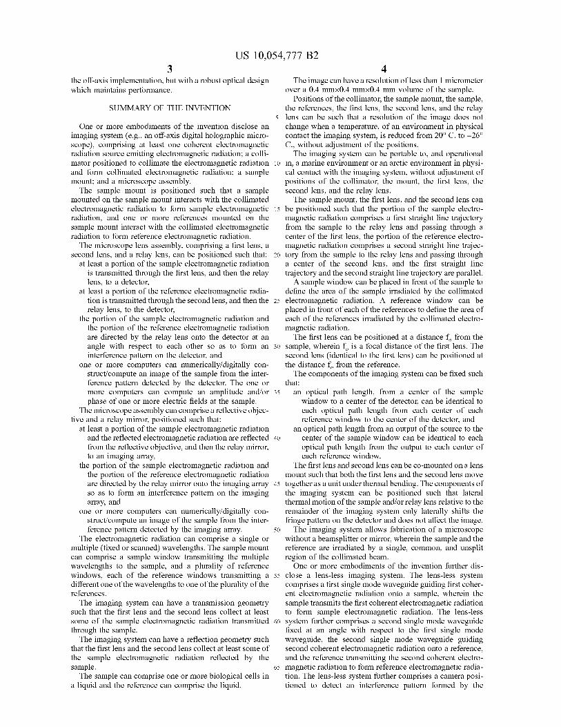
twin-beam digital holographic microscope in its laboratoryimplementation, according to one or more embodiments ofthe invention. FIG. 1(a) is a schematic showing the fourmain elements (discussed in the text): the source, the sample(specimen path is labeled Spec. and reference path is labeledRef.), the microscope, and the sensor. FIG. 1(b) is a solidmodel of the hardware, wherein the fiber-fed source assem-bly is at the bottom, the imaging camera is at the top, themicroscope optics (comprised of the two aspheric lenses andthe relay lens) are contained within the 300 mm long lenstube, and the three-axis stage between the source the micro-scope optics provides easy manual manipulation of thespecimen under study. FIG. 1(c) is a photograph of theinstrument in the laboratory, wherein a shutter over thecollimating lens protects against condensation, and is oper-ated remotely by a controller. FIG. 1(d) and FIG. 1(e) arecomputer aided design (CAD) drawings of the holographicmicroscope.FIG. 10 is a face view, and FIG. 1(g) is a cross-sectional
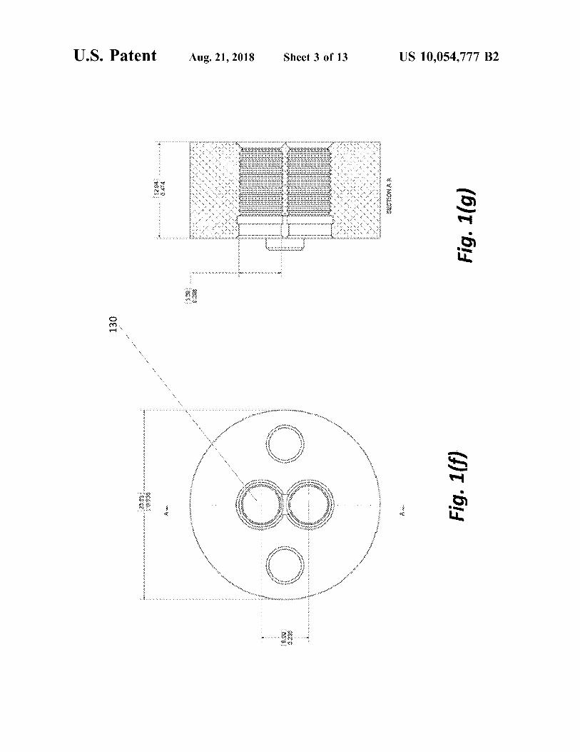
schematic, of a 3D printed asphere holder used to mount theobjectives in the holographic microscope, wherein dimen-sions are in millimeters (mm), according to one or moreembodiments of the invention.FIGS. 2(a), (b), (c) and (d) illustrate images showing
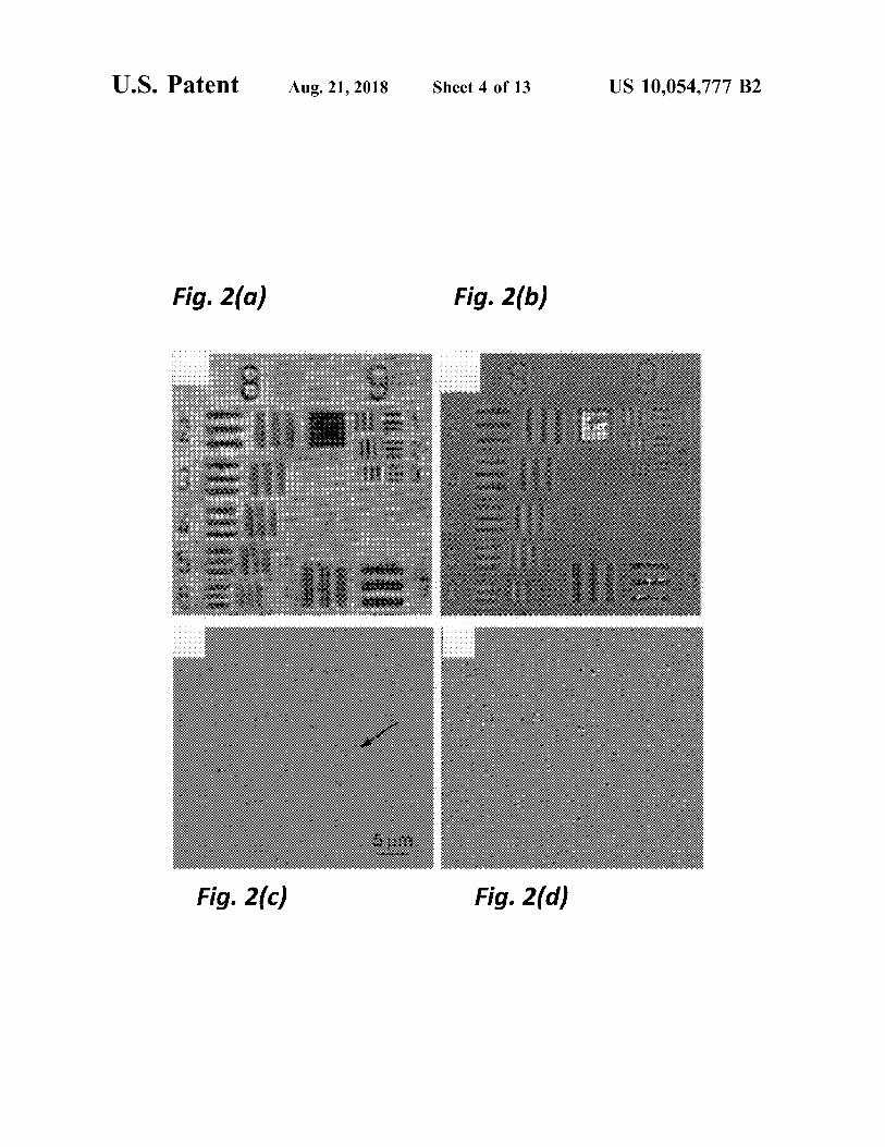
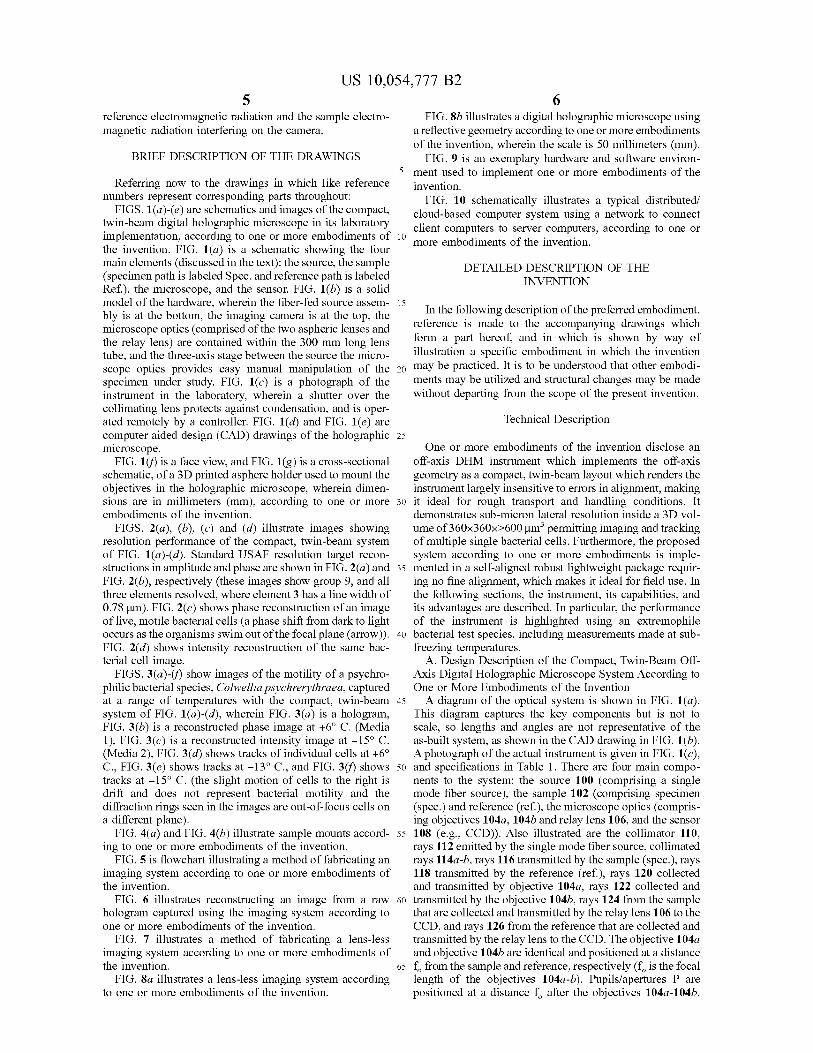
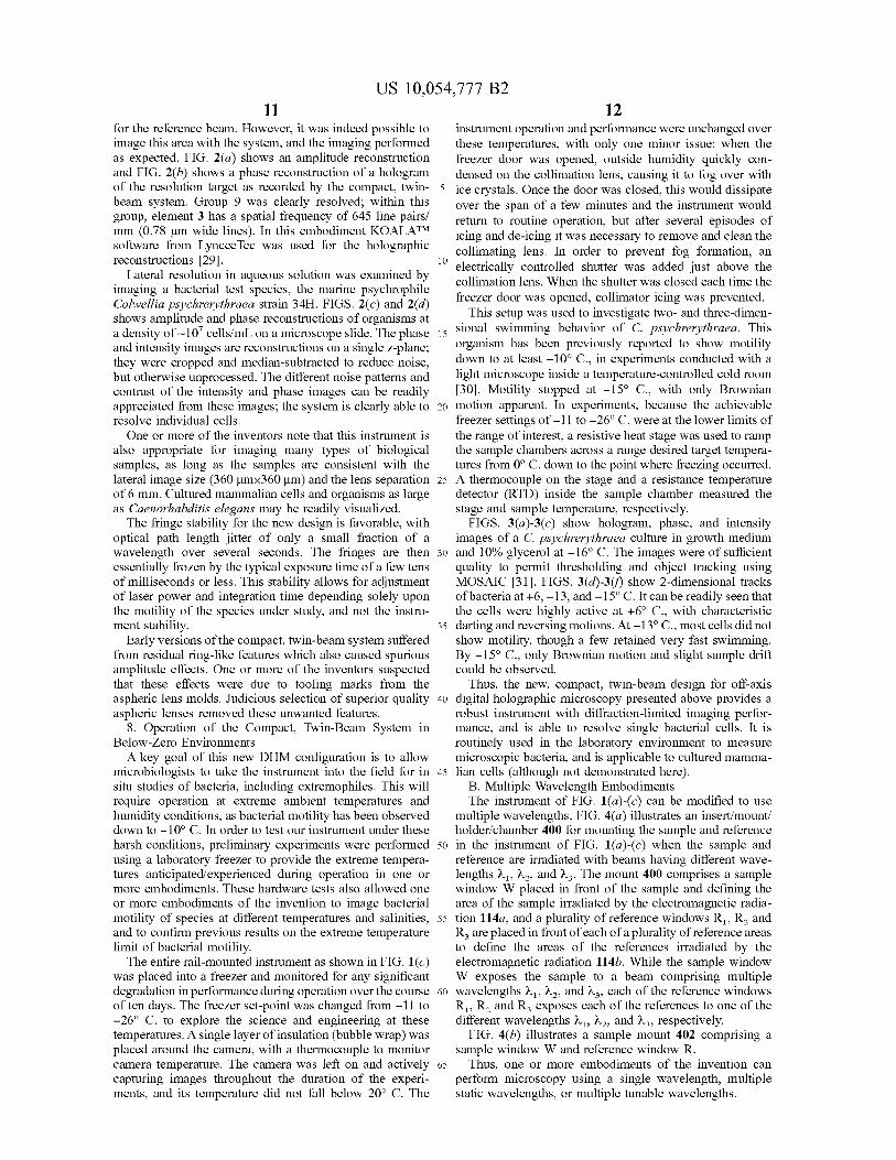
resolution performance of the compact, twin-beam systemof FIG. 1(a)-(d). Standard USAF resolution target recon-structions in amplitude and phase are shown in FIG. 2(a) andFIG. 2(b), respectively (these images show group 9, and allthree elements resolved, where element 3 has a line width of0.78 µm). FIG. 2(c) shows phase reconstruction of an imageof live, motile bacterial cells (a phase shift from dark to lightoccurs as the organisms swim out of the focal plane (arrow)).FIG. 2(d) shows intensity reconstruction of the same bac-terial cell image.
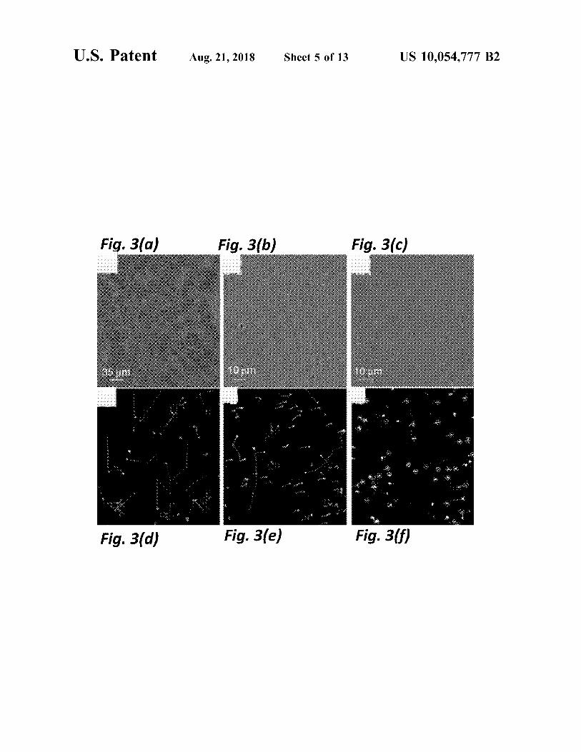
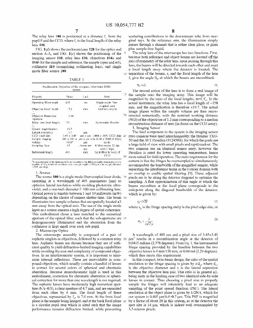
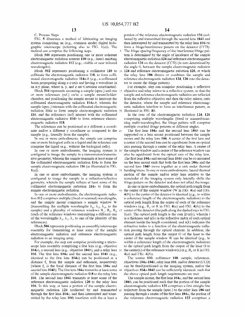
FIGS. 3(a)-(1) show images of the motility of a psychro-philic bacterial species, Colwellia psychrerythraea, capturedat a range of temperatures with the compact, twin-beamsystem of FIG. 1(a)-(d), wherein FIG. 3(a) is a hologram,FIG. 3(b) is a reconstructed phase image at +6° C. (Media1), FIG. 3(c) is a reconstructed intensity image at —15° C.(Media 2), FIG. 3(d) shows tracks of individual cells at +6°C., FIG. 3(e) shows tracks at —13° C., and FIG. 3(f) showstracks at —15° C. (the slight motion of cells to the right isdrift and does not represent bacterial motility and thediffraction rings seen in the images are out-of-focus cells ona different plane).
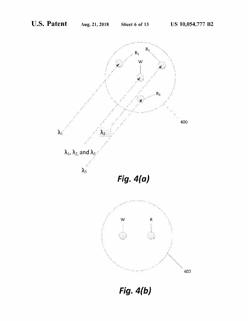
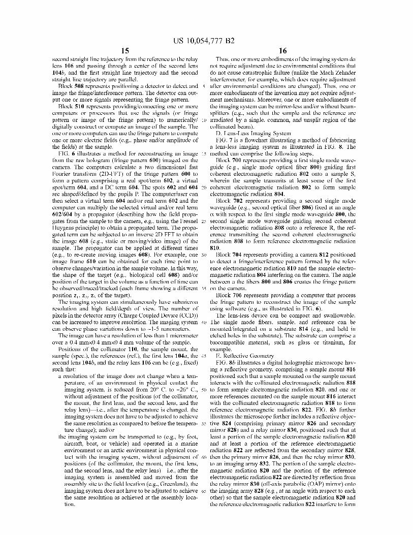
FIG. 4(a) and FIG. 4(b) illustrate sample mounts accord-ing to one or more embodiments of the invention.
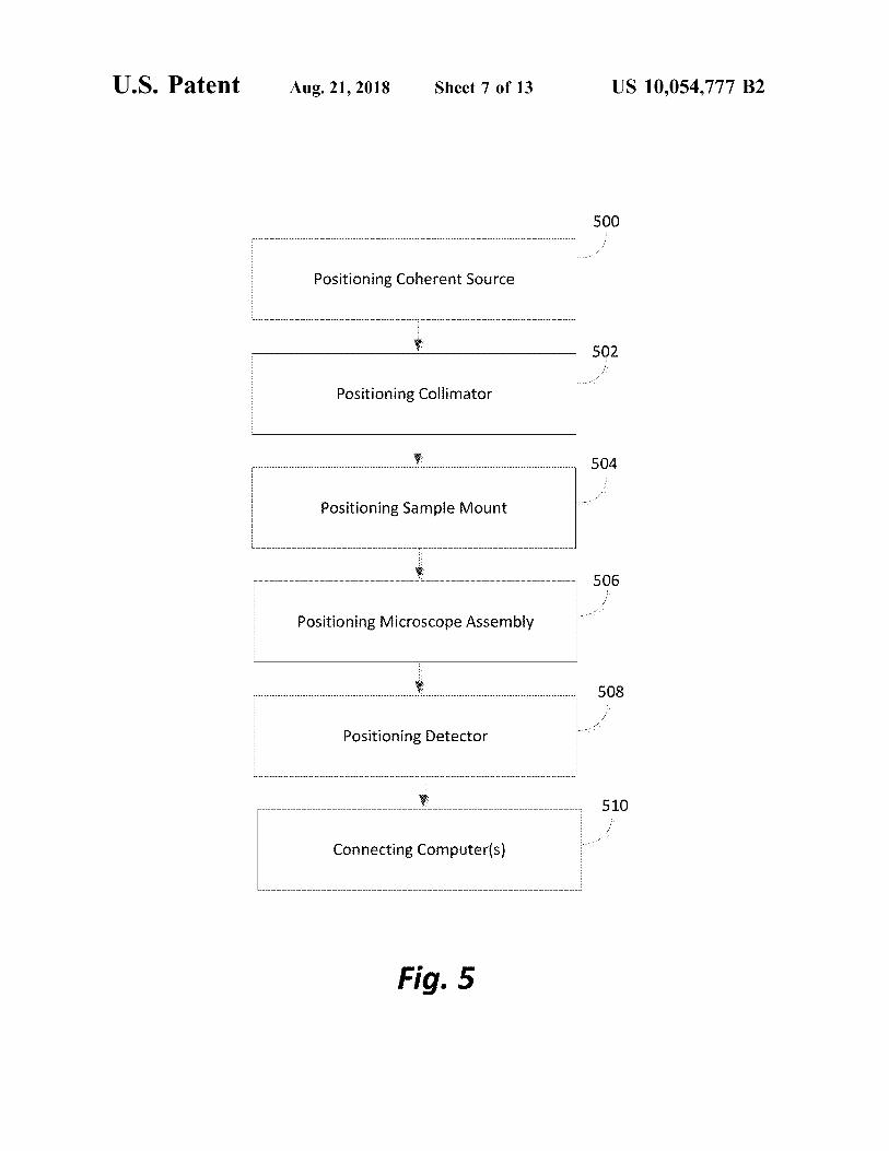
FIG. 5 is flowchart illustrating a method of fabricating animaging system according to one or more embodiments ofthe invention.
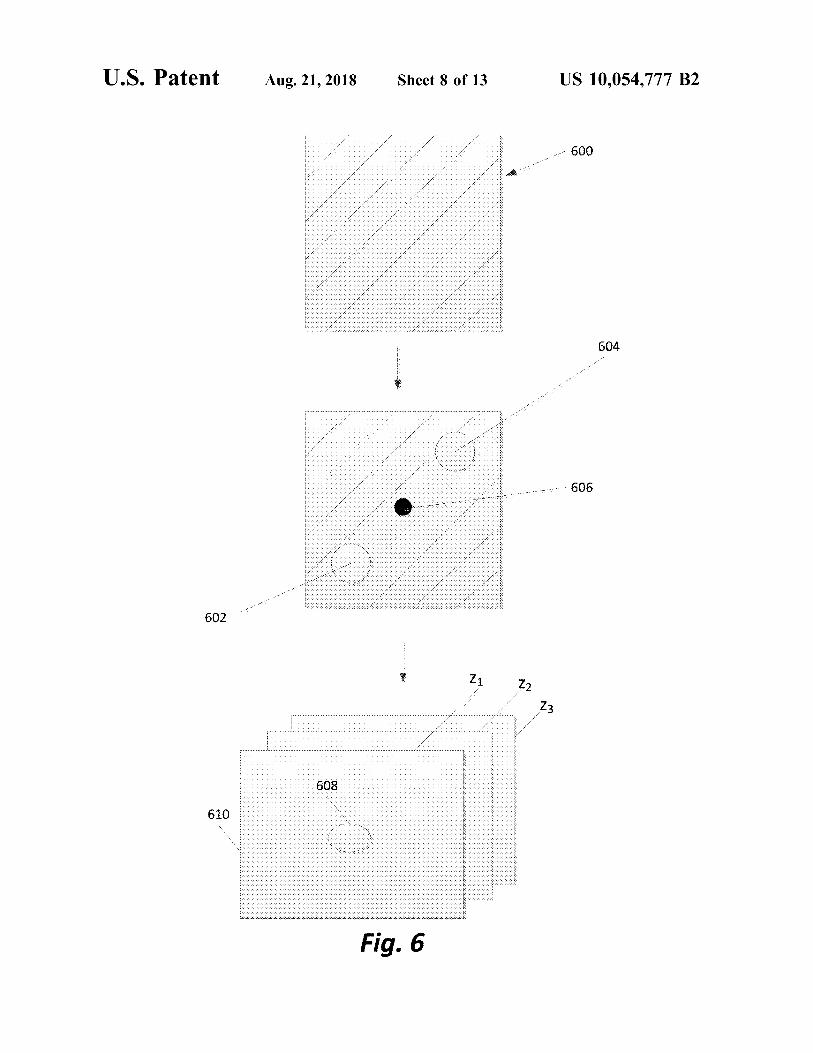
FIG. 6 illustrates reconstructing an image from a rawhologram captured using the imaging system according toone or more embodiments of the invention.
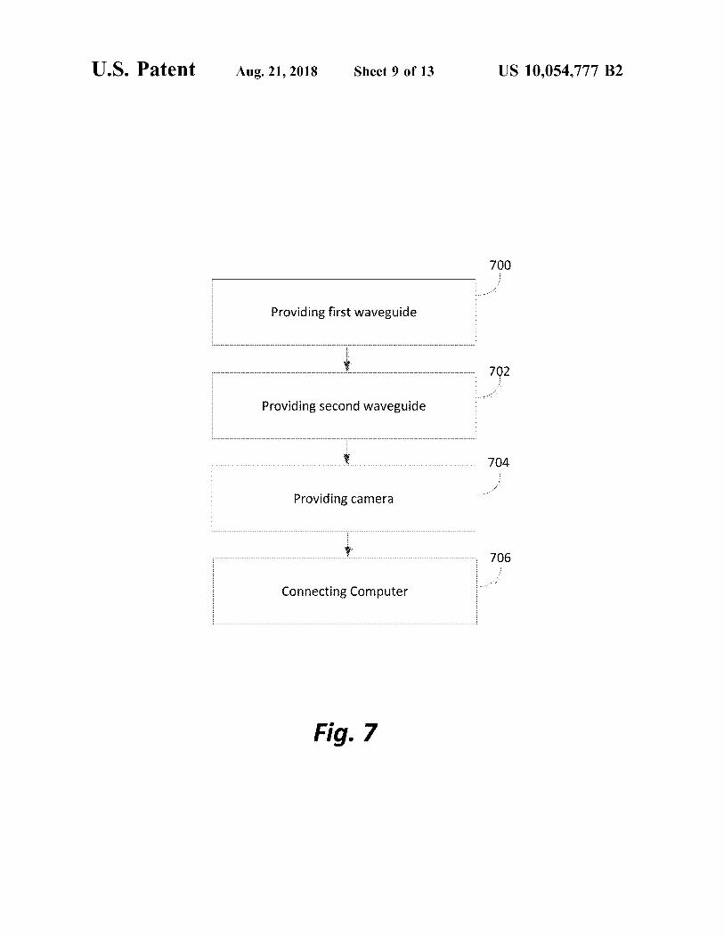
FIG. 7 illustrates a method of fabricating a lens-lessimaging system according to one or more embodiments ofthe invention.
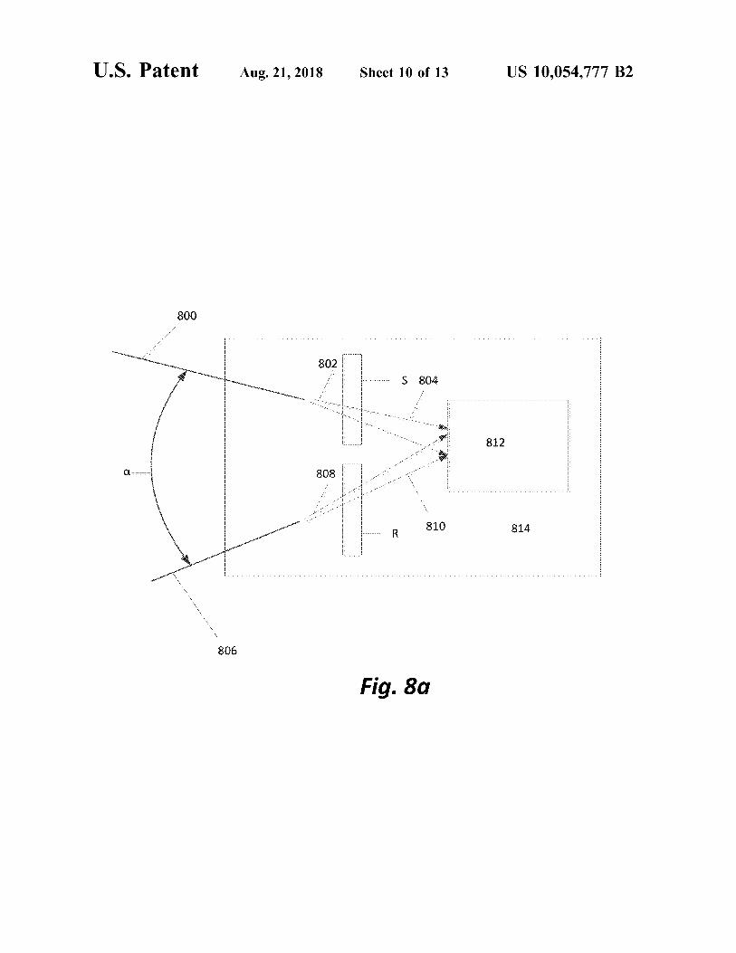
FIG. 8a illustrates a lens-less imaging system accordingto one or more embodiments of the invention.
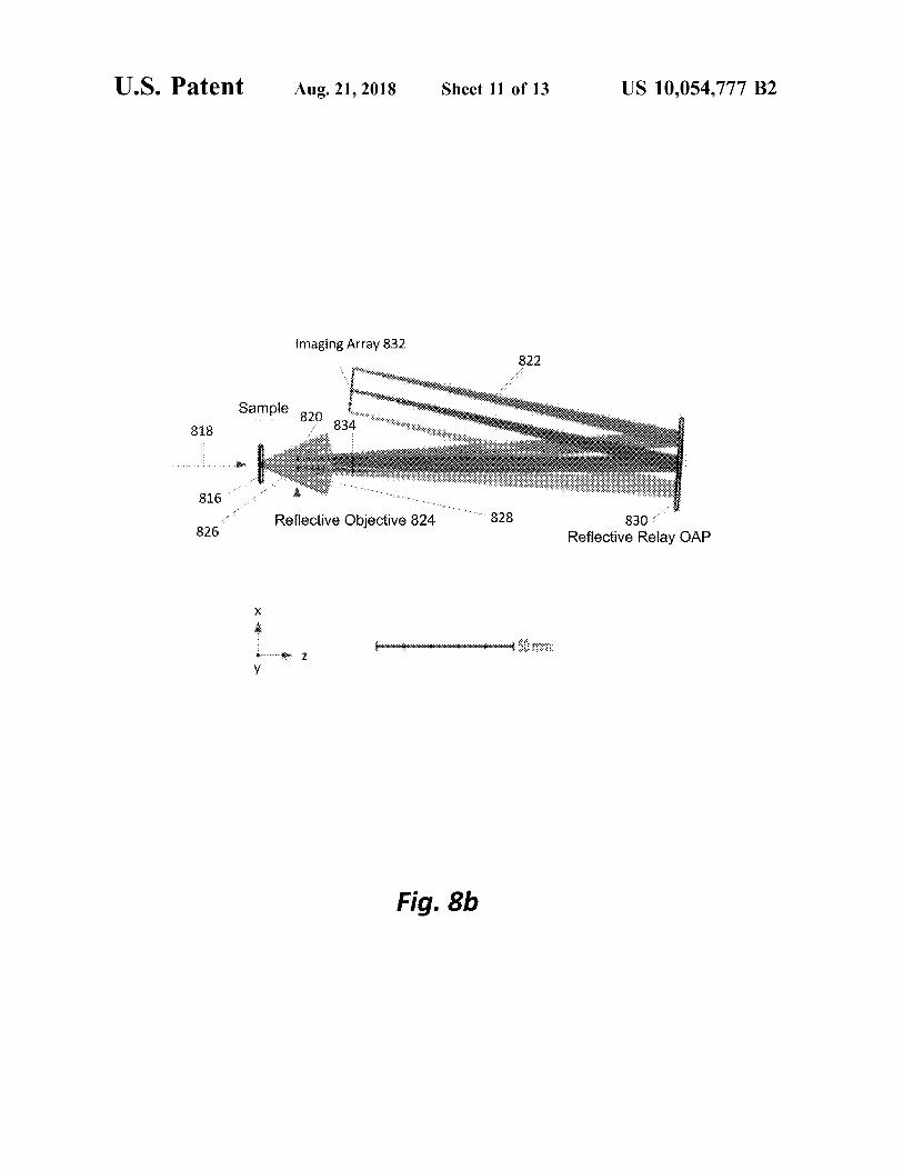
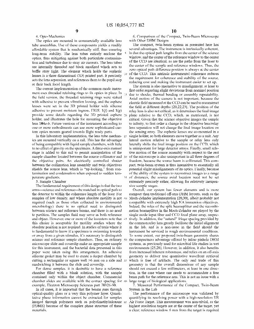
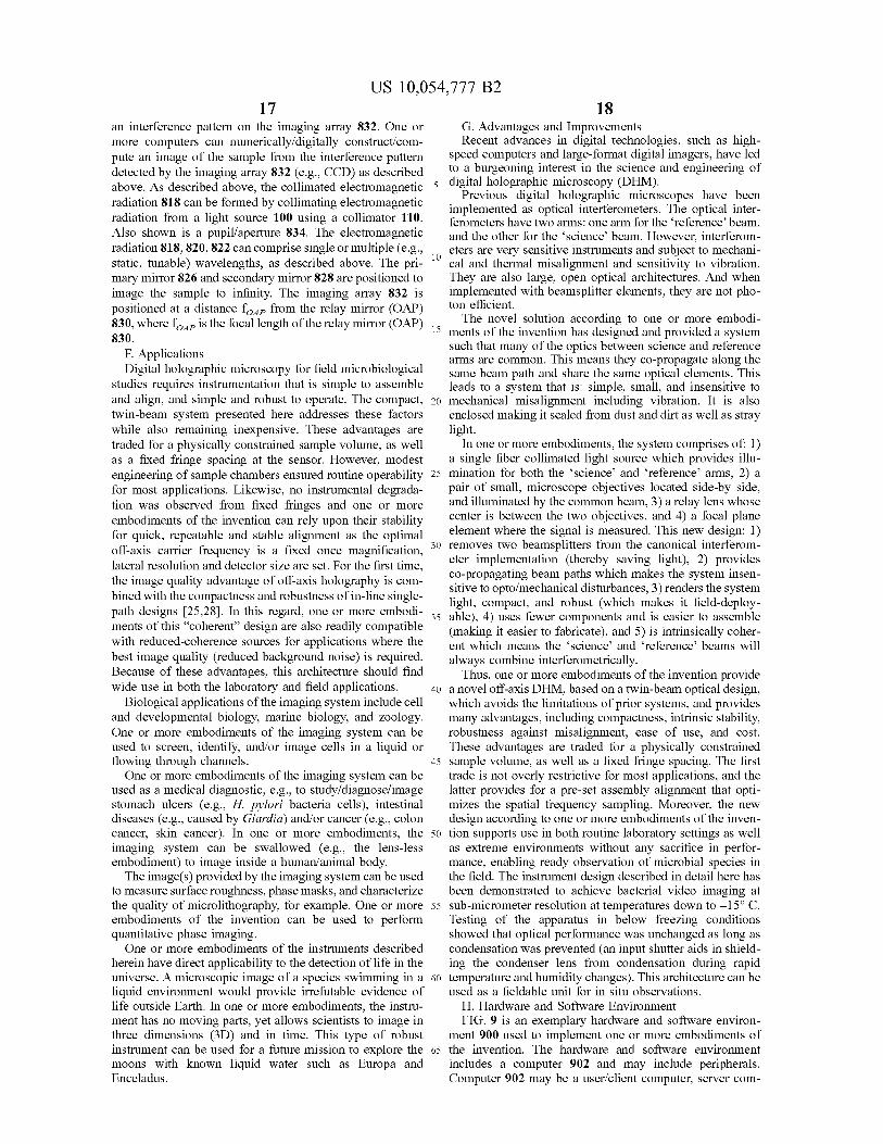
6FIG. 8b illustrates a digital holographic microscope using
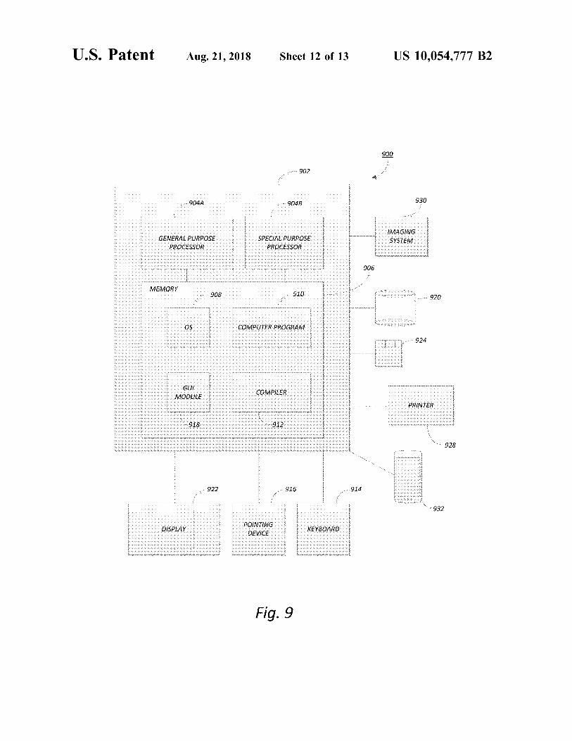
a reflective geometry according to one or more embodimentsof the invention, wherein the scale is 50 millimeters (mm).FIG. 9 is an exemplary hardware and software environ-
s ment used to implement one or more embodiments of theinvention.
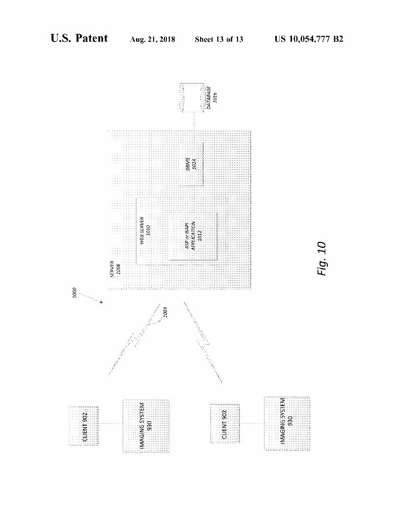
FIG. 10 schematically illustrates a typical distributed/cloud-based computer system using a network to connectclient computers to server computers, according to one or
10 more embodiments of the invention.
DETAILED DESCRIPTION OF THEINVENTION
15 In the following description of the preferred embodiment,reference is made to the accompanying drawings whichform a part hereof, and in which is shown by way ofillustration a specific embodiment in which the invention
20 may be practiced. It is to be understood that other embodi-ments may be utilized and structural changes may be madewithout departing from the scope of the present invention.
Technical Description
25
One or more embodiments of the invention disclose anoff-axis DHM instrument which implements the off-axisgeometry as a compact, twin-beam layout which renders theinstrument largely insensitive to errors in alignment, making
30 it ideal for rough transport and handling conditions. Itdemonstrates sub-micron lateral resolution inside a 3D vol-ume of 360x360x>600 µm3 permitting imaging and trackingof multiple single bacterial cells. Furthermore, the proposedsystem according to one or more embodiments is imple-
35 mented in a self-aligned robust lightweight package requir-ing no fine alignment, which makes it ideal for field use. Inthe following sections, the instrument, its capabilities, andits advantages are described. In particular, the performanceof the instrument is highlighted using an extremophile
4o bacterial test species, including measurements made at sub-freezing temperatures.A. Design Description of the Compact, Twin-Beam Off-
Axis Digital Holographic Microscope System According toOne or More Embodiments of the Invention
45 A diagram of the optical system is shown in FIG. 1(a).This diagram captures the key components but is not toscale, so lengths and angles are not representative of theas-built system, as shown in the CAD drawing in FIG. 1(b).A photograph of the actual instrument is given in FIG. 1(c),
5o and specifications in Table 1. There are four main compo-nents to the system: the source 100 (comprising a singlemode fiber source), the sample 102 (comprising specimen(spec.) and reference (ref.), the microscope optics (compris-ing objectives 104a, 104b and relay lens 106, and the sensor
55 108 (e.g., CCD)). Also illustrated are the collimator 110,rays 112 emitted by the single mode fiber source, collimatedrays 114a-b, rays 116 transmitted by the sample (spec.), rays118 transmitted by the reference (ref.), rays 120 collectedand transmitted by objective 104a, rays 122 collected and
60 transmitted by the objective 104b, rays 124 from the samplethat are collected and transmitted by the relay lens 106 to theCCD, and rays 126 from the reference that are collected andtransmitted by the relay lens to the CCD. The objective 104aand objective 104b are identical and positioned at a distance
65 to from the sample and reference, respectively (f is the focallength of the objectives 104a-b). Pupils/apertures P arepositioned at a distance to after the objectives 104a-104b.
US 10,054,777 B2
7The relay lens 106 is positioned at a distance f from thepupil P and the CCD, where f is the focal length of the relaylens 106.
FIG. 1(d) shows the enclosure/case 128 for the optics andsection A-A, and FIG. 1(e) shows the positioning of theimaging sensor 108, relay lens 106, objectives 104a and104b for the sample and reference, the sample (spec and ref),collimator 110 (comprising collimating lens), and singlemode fiber source 100.
TABLE 1
Fundamental Properties of the compact, twin-beam DHM
system
Property Value Unit Note
Operating Wavelength 405 nm Single-mode fiber-
coupled laser
Objective focal length- 7.6 mm Aspheric singlet
foObjective Numerical 0.30
Aperture
Relay lens focal length- 150 mm Achromatic Doublet
fSystem magnification 19.7
Lateral resolution 0.7 µm
CCD pixel size 3.45 x 3.45 µm x µm 2448 x 2050 CCD chip
Sample imaging 360 x 360 x µm x µm x In 2048 x 2048 (4 Mpx)
volume >600a µm mode
Sampling Rate 15 frames per 4 Mpx mode; 22 fps
sec with 1 Mpx
Instrument length 400 mm Input fiber to back of
CCD
aA measurement of the instrument lateral resolution for different depths demonstrated it iscapable of <1 µm lateral resolution over a sample depth of 900 µm. Our sample chamberis 600 µm deep.
1. SourceThe source 100 is a single mode fiber-coupled laser diode,
operating at a wavelength of 405 nanometers (nm) tooptimize lateral resolution while avoiding phototoxic ultra-violet, and a one-inch diameter X100 mm collimating lens.Optical power is tunable between 1 and 10 milliwatts (mw)depending on the choice of camera shutter time. The beamilluminates two sample volumes that are spatially located ±3
mm away from the optical axis. The use of the single modeinput as a source ensures a high degree of spatial coherence.This embodiment chose a lens matched to the numericalaperture of the optical fiber, such that the sub-apertures arehomogeneously illuminated and the aberration from thecollimator is kept small over each sub-pupil.
2. Microscope OpticsThe microscope assembly is composed of a pair of
aspheric singlets as objectives, followed by a common relaylens. Aspheric lenses are chosen because they are of suffi-cient quality to yield diffraction-limited imaging capabilitieswhile avoiding the cost and complexity of compound objec-tives. In an interferometric system, it is important to mini-mize internal reflections. These are unavoidable in com-pound objectives, which usually contain a handful of lensesto correct for several colors of spherical and chromaticaberration. Because monochromatic light is used in thisembodiment, correction for chromatic aberration or spheri-cal correction for more than one wavelength is not required.The aspheric lenses have moderately high numerical aper-ture (NA-0.3), a clear aperture of 4.7 mm, and are separatedfrom each other by 6 mm. The focal length of theseobjectives, represented by f , is 7.6 mm. At the front focalplane is the sample being imaged, and at the back focal planeis a circular pupil stop which is sized such that the imageperformance remains diffraction limited, while preventing
8scattering contributions in the downstream tube from mar-ginal rays. In the reference arm, the illumination simplypasses through a channel that is either clear glass, or glassplus sample-free liquid.
5 The relay lens of the microscope has two functions. First,because both reference and object beams are located off theaxis of symmetry of the relay lens, upon passing through thislens, the beams will be directed towards each other and meeta focal length away where the detector is located. The
to separation of the beams, s, and the focal length of the lensf give the angle 0f, at which the beams are recombined:
a f =sif (1)
The second action of the lens is to form a real image of15 the sample onto the imaging array. This image will be
magnified by the ratio of the focal lengths, m=f)f . In theactual instrument, the relay lens has a focal length of —150mm, and the magnification is therefore x19.7. The actualimage planes within the sample volume are then recon-
20 structed numerically, with the nominal working distance(WD) of the objectives of 1.2 mm corresponding to a medianreconstruction distance of zero (in-focus on the CCD array).
3. Imaging SensorThe final component in the system is the imaging sensor
25 (two cameras were used interchangeably, the Baumer TXG-50 and the AVT Prosilica GT2450B), for which the goals area large field of view with small pixels and rapid readout. Thetwo cameras use an identical sensor array, however theProsilica is rated for lower operating temperature, hence
30 more suited for field operation. The main requirement for thecamera is that the fringes be oversampled to simultaneouslyaccommodate the bandwidth of the magnified sample, whileseparating the interference terms in the Fourier domain withno overlap to enable spatial filtering [9]. These adjacent
35 pixels are to be along the detector diagonal to optimize thesampling. A first approximation of this angle at which thebeams recombine at the focal plane corresponds to themid-point along the diagonal bandwidth of the detector,which is given by:
40
s f>2~2P (2)
where sf is the fringe spacing and p is the pixel edge size, or
45 ;L(3)
Br < 212 p
A wavelength of 405 nin and a pixel size of 3.450.4550 µm2 results in a recombination angle at the detector of
0.0415 radians (2.378 degrees). From Eq. 1, the instrumentalfringe spacing provided by the baseline between the twoobjective lenses is 6 mm/150 mm, or 0.04 rad (2.29 degrees),which thus meets this requirement.
55 In this compact, twin-beam design, the ratio of the spatialresolution to the fringe spacing is given by s/do, where do,is the objective diameter and s is the lateral separationbetween the objective lens pair. This ratio is in general >_l,being unity in the limiting case of two identical side-by-side
60 lenses in contact. Thus choosing a pixel size to properlysample the fringes will inherently lead to an adequatesampling of the point spread function (PSF). The lateralresolution at the object plane is given by X/2NA, which forour system is 0.405 µm/0.6-0.7 µm. This PSF is magnified
65 by a factor of about 20 in this system, so at the detector thespot size is 14 µm, which is indeed well oversampled by3.5-micron pixels.
US 10,054,777 B2
94. Opto-MechanicsThe optics are mounted in commercially available lens
tube assemblies. Use of these components yields a readilyaffordable system that is mechanically stiff, thus ensuringlong-term stability. The lens tubes entirely enclose theoptics, thus mitigating against both particulate contamina-tion and turbulence due to stray air currents. The lens tubesare internally threaded and black anodized which acts tobaffle stray light. The element which holds the asphericlenses is a three dimensional (3D) printed part. It preciselysets the lens separation, and references them to the pupil stopat their back focal length.The current implementation of the common mode instru-
ment uses threaded retaining rings to fix optics in place. Inthe field version, the threaded retaining rings were stakedwith adhesive to prevent vibration loosing, and the aspherelenses were set in the 3D printed holder with siliconeadhesive to prevent moisture ingress. FIGS. 1(f) and 1(g)provide some details regarding the 3D printed asphereholder, and illustrates the hole for mounting the objectivelens 104a-b. Future versions of the instrument according toone or more embodiments can use more sophisticated cus-tom optics mounts geared towards flight ready parts.
In this laboratory implementation, the lens tube mechan-ics are mounted vertically on a rail. This has the advantageof being compatible with liquid sample chambers, with littleto no effect of gravity on the specimens. A three-axis manualstage is added to this rail to permit manipulation of thesample chamber located between the source collimator andthe objective pairs. An electrically controlled shutterbetween the collimation lens assembly and twin objectivesshields the source lens, which is "up-looking," from con-tamination and condensation when exposed to sudden tem-perature gradients.
5. Sample ChamberThe fundamental requirement of this design is that the two
arms science and reference be matched in optical path tothe detector to within the coherence length of the laser. Forsamples of low density, and where absolute motility is notrequired (such as those often collected in environmentalmicrobiology) there is no optical need to distinguishbetween science and reference beams, and there is no needto partition. The samples fluid may serve as both referenceand object. However, one or more of the inventors note thatthis choice is acceptable for motility studies where theabsolute position is not required. In studies of taxis where itis fundamental to know if a specimen is swimming towardsor away from a given stimulus, it's necessary to distinguishscience and reference sample chambers. Thus, an ordinarymicroscope slide and coverslip make an appropriate samplefor this instrument, and the bacterial data presented in thispaper were taken using this arrangement. An adhesivesilicone gasket may be used to create a deeper chamber bycutting a rectangular or square well >6 mm on a side andsandwiching it between the slide and coverslip.
For dense samples, it is desirable to have a referencechamber filled with a blank solution, with the samplecontained only within the object chamber. Commercialchamber slides are available with the correct spacing; forexample, Electron Microscopy Sciences part 70326-30.
In all cases, it is important that the beams pass throughoptical-quality glass or a very thin polymer layer. Quanti-tative phase information cannot be extracted for samplesimaged through polymers such as polydimethylsiloxane(PDMS) because of the complex phase structure of thesematerials.
106. Comparison of the Compact, Twin-Beam Microscope
with Other DHM DesignsThe compact, twin-beam system as presented here has
several advantages. The instrument is intrinsically coherent,5 in that the optical path lengths from the center of the science
window, and the center of the reference window to the centerof the CCD are identical, as are the paths from the laser tothe center of the sample and reference windows. Thus, thezero optical path difference position is always at the center
io of the CCD. This intrinsic instrumental coherence reducesthe requirement for coherence and stability of the source,reducing cost and making the instrument easier to set up.The system is also insensitive to misalignment, at least to
first order regarding slight deviations from nominal position15 due to shocks, thermal bending or assembly repeatability.
Axial motion of the camera is not important, because theelectric field measured at the CCD can be used to reconstructthe field at different depths [20,22,23]. The position of therelay lens is also not critical, as it determines the final image
20 plane relative to the CCD, which, as mentioned, is notcritical. Given that the science objective images the sampleto infinity, to first order a change in the objective lens/relaylens separation will not change the final image location onthe sensing array. The aspheric lenses are co-mounted in a
25 single holder, so both elements move together as a unit. Anylateral motion relative to the sample or relay lens onlylaterally shifts the final image position on the CCD, whichis unimportant for large detector arrays. Finally, small rela-tive motion of the source assembly with respect to the rest
30 of the microscope is also unimportant in all three degrees offreedom, because the source beam is collimated. This com-pact, twin-beam system is thus insensitive to essentially allpotential slight misalignments of its optics. Finally, becauseof the ability of the system to reconstruct images to a range
35 of distances, the source axial location need not be setextremely precisely either, allowing for relatively inexpen-sive sample stages.
Overall, our system has fewer elements and is morecompact than traditional off-axis DHM layouts, such as the
40 Mach-Zehnder implementation [20,30], albeit probably notcompatible with extremely high NA immersion objectives.Indeed, the roles of the split beamsplitter and the recombi-nation beamsplitter in the Mach-Zehnder are played by thesingle mode input fiber and CCD focal plane array, respec-
45 tively. In addition, the "natural" fringe spacing provided bythe common relay lens greatly facilitate the initial alignmentin the lab, and is a non-issue in the field should theinstrument be serviced in rough environmental conditions.To some extent, our proposed twin-beam geometry shares
50 the compactness advantage offered by inline pinhole DHMsystems, as previously used for microbial life studies in wetenvironments [25,28]. However, in addition, it also benefitsfrom increased inherent robustness, and relies on an off-axisgeometry to deliver true quantitative wavefront retrieval
55 which is free of artifacts. The only real trade of thisgeometry is that the overall dimensions of any sampleshould not exceed a few millimeters, at least in one direc-tion, in the case where one needs to accommodate a freebeam path for the reference arm. This is not an issue with a
60 large range of biological applications.7. Measured Performance of the Compact, Twin-Beam
System in the LabThe performance of the microscope was validated by
quantifying its resolving power with a high-resolution US65 Air Force Target. This measurement was non-trivial, as the
highest resolution targets are at the center of the target, yeta clear, reference window 6 mm from the target is required
US 10,054,777 B211
for the reference beam. However, it was indeed possible toimage this area with the system, and the imaging performedas expected. FIG. 2(a) shows an amplitude reconstructionand FIG. 2(b) shows a phase reconstruction of a hologramof the resolution target as recorded by the compact, twin- 5
beam system. Group 9 was clearly resolved; within thisgroup, element 3 has a spatial frequency of 645 line pairs/mm (0.78 µm wide lines). In this embodiment KOALATMsoftware from LynceeTec was used for the holographicreconstructions [29]. 10
Lateral resolution in aqueous solution was examined byimaging a bacterial test species, the marine psychrophileColwellia psychrerythraea strain 34H. FIGS. 2(c) and 2(d)shows amplitude and phase reconstructions of organisms ata density of —10' cells/mL on a microscope slide. The phase 15and intensity images are reconstructions on a single z-plane;they were cropped and median-subtracted to reduce noise,but otherwise unprocessed. The different noise patterns andcontrast of the intensity and phase images can be readilyappreciated from these images; the system is clearly able to 20resolve individual cells.One or more of the inventors note that this instrument is
also appropriate for imaging many types of biologicalsamples, as long as the samples are consistent with thelateral image size (360 µmx360 µm) and the lens separation 25of 6 mm. Cultured mammalian cells and organisms as largeas Caenorhabditis elegans may be readily visualized.The fringe stability for the new design is favorable, with
optical path length jitter of only a small fraction of awavelength over several seconds. The fringes are then 30essentially frozen by the typical exposure time of a few tensof milliseconds or less. This stability allows for adjustmentof laser power and integration time depending solely uponthe motility of the species under study, and not the instru-ment stability. 35
Early versions of the compact, twin-beam system sufferedfrom residual ring-like features which also caused spuriousamplitude effects. One or more of the inventors suspectedthat these effects were due to tooling marks from theaspheric lens molds. Judicious selection of superior quality 40aspheric lenses removed these unwanted features.
8. Operation of the Compact, Twin-Beam System inBelow-Zero EnvironmentsA key goal of this new DHM configuration is to allow
microbiologists to take the instrument into the field for in 45situ studies of bacteria, including extremophiles. This willrequire operation at extreme ambient temperatures andhumidity conditions, as bacterial motility has been observeddown to —10° C. In order to test our instrument under theseharsh conditions, preliminary experiments were performed 50using a laboratory freezer to provide the extreme tempera-tures anticipated/experienced during operation in one ormore embodiments. These hardware tests also allowed oneor more embodiments of the invention to image bacterialmotility of species at different temperatures and salinities, 55and to confirm previous results on the extreme temperaturelimit of bacterial motility.The entire rail-mounted instrument as shown in FIG. 1(c)
was placed into a freezer and monitored for any significantdegradation in performance during operation over the course 60of ten days. The freezer set-point was changed from —11 to—26° C. to explore the science and engineering at thesetemperatures. A single layer of insulation (bubble wrap) wasplaced around the camera, with a thermocouple to monitorcamera temperature. The camera was left on and actively 65capturing images throughout the duration of the experi-ments, and its temperature did not fall below 20° C. The
12instrument operation and performance were unchanged overthese temperatures, with only one minor issue: when thefreezer door was opened, outside humidity quickly con-densed on the collimation lens, causing it to fog over withice crystals. Once the door was closed, this would dissipateover the span of a few minutes and the instrument wouldreturn to routine operation, but after several episodes oficing and de-icing it was necessary to remove and clean thecollimating lens. In order to prevent fog formation, anelectrically controlled shutter was added just above thecollimation lens. When the shutter was closed each time thefreezer door was opened, collimator icing was prevented.
This setup was used to investigate two- and three-dimen-sional swimming behavior of C. psychrerythraea. Thisorganism has been previously reported to show motilitydown to at least —10° C., in experiments conducted with alight microscope inside a temperature-controlled cold room[30]. Motility stopped at —15° C., with only Brownianmotion apparent. In experiments, because the achievablefreezer settings of —11 to —26° C. were at the lower limits ofthe range of interest, a resistive heat stage was used to rampthe sample chambers across a range desired target tempera-tures from 0° C. down to the point where freezing occurred.A thermocouple on the stage and a resistance temperaturedetector (RTD) inside the sample chamber measured thestage and sample temperature, respectively.FIGS. 3(a)-3(c) show hologram, phase, and intensity
images of a C. psychrerythraea culture in growth mediumand 10% glycerol at —16° C. The images were of sufficientquality to permit thresholding and object tracking usingMOSAIC [31]. FIGS. 3(d)-3(f) show 2-dimensional tracksof bacteria at +6, —13, and —15° C. It can be readily seen thatthe cells were highly active at +6° C., with characteristicdarting and reversing motions. At —13° C., most cells did notshow motility, though a few retained very fast swimming.By —15° C., only Brownian motion and slight sample driftcould be observed.
Thus, the new, compact, twin-beam design for off-axisdigital holographic microscopy presented above provides arobust instrument with diffraction-limited imaging perfor-mance, and is able to resolve single bacterial cells. It isroutinely used in the laboratory environment to measuremicroscopic bacteria, and is applicable to cultured mamma-lian cells (although not demonstrated here).B. Multiple Wavelength EmbodimentsThe instrument of FIG. 1(a)-(c) can be modified to use
multiple wavelengths. FIG. 4(a) illustrates an insert/mount/holder/chamber 400 for mounting the sample and referencein the instrument of FIG. 1(a)-(c) when the sample andreference are irradiated with beams having different wave-lengths X11 X2, and X3. The mount 400 comprises a samplewindow W placed in front of the sample and defining thearea of the sample irradiated by the electromagnetic radia-tion 114a, and a plurality of reference windows R,, R2 andR3 are placed in front of each of a plurality of reference areasto define the areas of the references irradiated by theelectromagnetic radiation 114b. While the sample windowW exposes the sample to a beam comprising multiplewavelengths X11 X2, and X31 each of the reference windowsRl, R2 and R3 exposes each of the references to one of thedifferent wavelengths X,, X2, and X3, respectively.FIG. 4(b) illustrates a sample mount 402 comprising a
sample window W and reference window R.Thus, one or more embodiments of the invention can
perform microscopy using a single wavelength, multiplestatic wavelengths, or multiple tunable wavelengths.
US 10,054,777 B2
13C. Process StepsFIG. 5 illustrates a method of fabricating an imaging
system comprising an (e.g., common mode) digital holo-graphic microscope (referring also to FIG. 1(a)). Themethod can comprise the following steps.
Block 500 represents positioning one or more coherentelectromagnetic radiation sources 100 (e.g., laser) emittingelectromagnetic radiation 112 (e.g., visible or near infraredwavelengths).
Block 502 represents positioning a collimator 110 tocollimate the electromagnetic radiation 110, to form colli-mated electromagnetic radiation 114a-b (e.g., a collimatedbeam propagating along a z-axis and having a wavefront inan x-y plane, where x, y, and z are Cartesian coordinates).
Block 504 represents mounting a sample (spec.) and oneor more references (ref.) on/in a sample mount/holder/chamber, and positioning the sample mount to intercept thecollimated electromagnetic radiation 114a-b, wherein thesample (spec.) interacts with the collimated electromagneticradiation 114a to form sample electromagnetic radiation116, and the references (ref) interact with the collimatedelectromagnetic radiation 114b to form reference electro-magnetic radiation 118.The references can be positioned at a different x coordi-
nate and/or a different y coordinate as compared to thesample (e.g., laterally from the sample).
In one or more embodiments, the sample can compriseone or more biological cells in a liquid and the reference cancomprise the liquid (e.g., without the biological cells).
In one or more embodiments, the imaging system isconfigured to image the sample in a transmission/transmis-sive geometry, wherein the sample transmits at least some ofthe collimated electromagnetic radiation 114a to form thesample electromagnetic radiation 116 (as illustrated in FIG.1(a)).
In one or more embodiments, the imaging system isconfigured to image the sample in a reflection/reflectivegeometry, wherein the sample reflects at least some of thecollimated electromagnetic radiation 114a to form thesample electromagnetic radiation.
In one or more embodiments, the electromagnetic radia-tion 112 comprises multiple (fixed or scanned) wavelengths,and the sample mount comprises a sample window W(transmitting the multiple wavelengths X11 X21 a31 to thesample) and a plurality of reference windows R1, R2, R3(each of the reference windows transmitting a different oneof the wavelengths X1 X21 X3 to one of the plurality of thereferences).
Block 506 represents positioning an assembly/microscopeassembly for transmitting at least some of the sampleelectromagnetic radiation and reference electromagneticradiation to an imaging array.
For example, the step can comprise positioning a micro-scope lens assembly comprising a first lens (e.g., objective104a), a second lens (e.g., objective 104b), and a relay lens106. The first lens 104a and the second lens 104b (e.g.,identical to the first lens 104a) can be positioned at adistance f from the sample and reference, respectively(where f is the focal distance of the first lens 104a andsecond lens 104b). The first lens 104a transmits at least someof the sample electromagnetic radiation 118 to the relay lens106. The second lens 104b transmits at least some of thereference electromagnetic radiation 120 to the relay lens106. In this way, at least a portion of the sample electro-magnetic radiation 124 (collected by and transmittedthrough the first lens 104a, and then intercepted and trans-mitted by the relay lens 106) interferes with the at least a
14portion of the reference electromagnetic radiation 126 (col-lected by and transmitted through the second lens 104b andthen intercepted by and transmitted by the relay lens 106) toform a fringe/interference pattern on the detector (CCD).
5 The fringe spacing/frequency of the interference/fringe pat-tern is determined by the angle of incidence of the sampleelectromagnetic radiation 124 and reference electromagneticradiation 126 on the detector (CCD) (in turn determined bythe angle 0, between the sample electromagnetic radiation
io 124 and reference electromagnetic radiation 126, at whichthe relay lens 106 directs or combines the sample andreference electromagnetic radiation 124, 126 onto the detec-tor to create the fringe pattern).
For example, step can comprise positioning a reflective15 objective and relay mirror in a reflective system, so that the
sample and reference electromagnetic radiation are reflectedfrom the reflective objective and then the relay mirror, ontothe detector, where the sample and reference electromag-netic radiation interfere to form an interference pattern, as
20 illustrated in FIG. 8b.In the case of the electromagnetic radiation 124, 126
comprising multiple wavelengths (fixed or scanned/scan-ning multi-wavelengths), the fringe pattern will comprisemultiple overlaid fringe patterns at different angles.
25 The first lens 104a and the second lens 104b can besupported on a lens mount positioned between the samplemount and the relay lens 106. A center of the first lens anda center of the second lens can be equidistant from an opticalaxis passing through a center of the relay lens. A center of
30 the sample window and a center of the reference window canalso be equidistant from the optical axis of the relay lens.The first lens 104a and second lens 104b can be co-mountedon the lens mount such that both the first lens 104a and thesecond lens 104b move together as a unit under thermal
35 bending/stress. In one or more embodiments, lateral thermalmotion of the sample and/or relay lens relative to theremainder of the imaging system only laterally shifts thefringe pattern on the detector and does not affect the image.
In one or more embodiments, the optical path length from40 the center of the sample window (W in FIG. 4(a) and FIG.
4(b)) to the center of the detector is identical (e.g., to withina coherence length of the electromagnetic radiation) to theoptical path length from the center of each of the referencewindows (e.g., R, or R in FIG. 4(a) and FIG. 4(b)) to the
45 center of the detector (the path along the dashed rays in FIG.1(a)). The optical path length is the sum 2:t-n(X), wherein tis a thickness and n(X) is the refractive index of each opticalelement inside the length considered, and n(X) indicates therefractive index is a function of the electromagnetic radia-
50 tion passing through the optical element. In addition, theoptical path length from the output O of the laser to thecenter of the sample window W can be identical (e.g., towithin a coherence length of the electromagnetic radiation)to the optical path length from the output of the laser O to
55 the center(s) of the reference window(s) (e.g. R, or R in FIG.4(a) and FIG. 4(b)).The source 100, collimator 108, sample, references,
objectives 104a-104b, relay lens 106, and/or detector (CCD)can be fixed/positioned in the imaging system, and/or the
60 objectives 104a-104b can be sufficiently identical, such thatthe above optical path length requirements are met.The sample mount, the first lens 104a, and the second lens
104b, can be positioned such that the portion of the sampleelectromagnetic radiation 120 comprises a first straight line
65 trajectory from the sample (spec.) to the relay lens 106 andpassing through a center of the first lens 104a, the portion ofthe reference electromagnetic radiation 122 comprises a
US 10,054,777 B2
15second straight line trajectory from the reference to the relaylens 106 and passing through a center of the second lens104b, and the first straight line trajectory and the secondstraight line trajectory are parallel.
Block 508 represents positioning a detector to detect andimage the fringe/interference pattern. The detector can out-put one or more signals representing the fringe pattern.
Block 510 represents providing/connecting one or morecomputers or processors that use the signals (or fringepattern or image of the fringe pattern) to numerically/digitally construct or compute an image of the sample. Theone or more computers can use the fringe pattern to computeone or more electric fields (e.g., phase and/or amplitude ofthe fields) at the sample.
FIG. 6 illustrates a method for reconstructing an imagefrom the raw hologram (fringe pattern 600) imaged on thecamera. The computers calculate a two dimensional fastFourier transform (2D-FFT) of the fringe pattern 600 toform a pattern comprising a real spot/term 602, a virtualspot/term 604, and a DC term 604. The spots 602 and 604are shaped/defined by the pupils P. The computer/user canthen select a virtual term 604 and/or real term 602 and thecomputer can multiply the selected virtual and/or real term602/604 by a propagator (describing how the field propa-gates from the sample to the camera, e.g., using the FresnelHuygens principle) to obtain a propagated term. The propa-gated term can be subjected to an inverse 2D FFT to obtainthe image 608 (e.g., static or moving/video image) of thesample. The propagator can be applied at different times(e.g., to re-create moving images 608). For example, oneimage frame 610 can be obtained for each time point toobserve changes/variation in the sample volume. In this way,the shape of the target (e.g., biological cell 608) and/orposition of the target in the volume as a function of time canbe observed/traced/tracked (each frame showing a differentposition zl, z21 z3 of the target).The imaging system can simultaneously have submicron
resolution and high field/depth of view. The number ofpixels in the detector array (Charge Coupled Device (CCD))can be increased to improve resolution. The imaging systemcan observe phase variations down to —1-5 nanometers.The image can have a resolution of less than 1 micrometer
over a 0.4 mmx0.4 mmx0.4 mm volume of the sample.Positions of the collimator 110, the sample mount, the
sample (spec.), the references (ref.), the first lens 104a, thesecond lens 104b, and the relay lens 106 can be (e.g., fixed)such that:
a resolution of the image does not change when a tem-perature, of an environment in physical contact theimaging system, is reduced from 20° C. to —26° C.,without adjustment of the positions (of the collimator,the mount, the first lens, and the second lens, and therelay lens) i.e., after the temperature is changed, theimaging system does not have to be adjusted to achievethe same resolution as compared to before the tempera-ture change); and/or
the imaging system can be transported to (e.g., by foot,aircraft, boat, or vehicle) and operated in a marineenvironment or an arctic environment in physical con-tact with the imaging system, without adjustment ofpositions (of the collimator, the mount, the first lens,and the second lens, and the relay lens) i.e., after theimaging system is assembled and moved from theassembly site to the field location (e.g., Greenland), theimaging system does not have to be adjusted to achievethe same resolution as achieved at the assembly loca-tion.
16Thus, one or more embodiments of the imaging system do
not require adjustment due to environmental conditions thatdo not cause catastrophic failure (unlike the Mach Zehnderinterferometer, for example, which does require adjustment
5 after environmental conditions are changed). Thus, one ormore embodiments of the invention may not require adjust-ment mechanisms. Moreover, one or more embodiments ofthe imaging system can be mirror-less and/or without beam-splitters (e.g., such that the sample and the reference are
io irradiated by a single, common, and unsplit region of thecollimated beam).D. Lens-Less Imaging SystemFIG. 7 is a flowchart illustrating a method of fabricating
a lens-less imaging system as illustrated in FIG. 8. The15 method can comprise the following steps.
Block 700 represents providing a first single mode wave-guide (e.g., single mode optical fiber 800) guiding firstcoherent electromagnetic radiation 802 onto a sample S,wherein the sample transmits at least some of the first
20 coherent electromagnetic radiation 802 to form sampleelectromagnetic radiation 804.
Block 702 represents providing a second single modewaveguide (e.g., second optical fiber 806) fixed at an anglea with respect to the first single mode waveguide 800, the
25 second single mode waveguide guiding second coherentelectromagnetic radiation 808 onto a reference R, the ref-erence transmitting the second coherent electromagneticradiation 808 to form reference electromagnetic radiation810.
30 Block 704 represents providing a camera 812 positionedto detect a fringe/interference pattern formed by the refer-ence electromagnetic radiation 810 and the sample electro-magnetic radiation 804 interfering on the camera. The anglebetween a the fibers 800 and 806 creates the fringe pattern
35 on the camera.Block 706 represents providing a computer that process
the fringe pattern to reconstruct the image of the sampleusing software (e.g., as illustrated in FIG. 6).The lens-less device can be compact and swallowable.
4o The single mode fibers, sample, and reference can bemounted/integrated on a substrate 814 (e.g., and held inetched holes in the substrate). The substrate can comprise abiocompatible material, such as glass or titanium, forexample.
45 E. Reflective GeometryFIG. 8b illustrates a digital holographic microscope hav-
ing a reflective geometry, comprising a sample mount 816positioned such that a sample mounted on the sample mountinteracts with the collimated electromagnetic radiation 818
50 to form sample electromagnetic radiation 820, and one ormore references mounted on the sample mount 816 interactwith the collimated electromagnetic radiation 818 to formreference electromagnetic radiation 822. FIG. 8b furtherillustrates the microscope further includes a reflective objec-
55 tive 824 (comprising primary mirror 826 and secondarymirror 828) and a relay mirror 830, positioned such that atleast a portion of the sample electromagnetic radiation 820and at least a portion of the reference electromagneticradiation 822 are reflected from the secondary mirror 828,
60 then the primary mirror 826, and then the relay mirror 830,to an imaging array 832. The portion of the sample electro-magnetic radiation 820 and the portion of the referenceelectromagnetic radiation 822 are directed by reflection fromthe relay mirror 830 (off-axis parabolic (OAP) mirror) onto
65 the imaging array 828 (e.g., at an angle with respect to eachother) so that the sample electromagnetic radiation 820 andthe reference electromagnetic radiation 822 interfere to form
US 10,054,777 B2
17an interference pattern on the imaging array 832. One ormore computers can numerically/digitally construct/com-pute an image of the sample from the interference patterndetected by the imaging array 832 (e.g., CCD) as describedabove. As described above, the collimated electromagneticradiation 818 can be formed by collimating electromagneticradiation from a light source 100 using a collimator 110.Also shown is a pupil/aperture 834. The electromagneticradiation 818, 820, 822 can comprise single or multiple (e.g.,static, tunable) wavelengths, as described above. The pri-mary mirror 826 and secondary mirror 828 are positioned toimage the sample to infinity. The imaging array 832 ispositioned at a distance foAP from the relay mirror (OAP)830, where foAP is the focal length of the relay mirror (OAP)830.
F. ApplicationsDigital holographic microscopy for field microbiological
studies requires instrumentation that is simple to assembleand align, and simple and robust to operate. The compact,twin-beam system presented here addresses these factorswhile also remaining inexpensive. These advantages aretraded for a physically constrained sample volume, as wellas a fixed fringe spacing at the sensor. However, modestengineering of sample chambers ensured routine operabilityfor most applications. Likewise, no instrumental degrada-tion was observed from fixed fringes and one or moreembodiments of the invention can rely upon their stabilityfor quick, repeatable and stable alignment as the optimaloff-axis carrier frequency is a fixed once magnification,lateral resolution and detector size are set. For the first time,the image quality advantage of off-axis holography is com-bined with the compactness and robustness of in-line single-path designs [25,28]. In this regard, one or more embodi-ments of this "coherent" design are also readily compatiblewith reduced-coherence sources for applications where thebest image quality (reduced background noise) is required.Because of these advantages, this architecture should findwide use in both the laboratory and field applications.
Biological applications of the imaging system include celland developmental biology, marine biology, and zoology.One or more embodiments of the imaging system can beused to screen, identify, and/or image cells in a liquid orflowing through channels.One or more embodiments of the imaging system can be
used as a medical diagnostic, e.g., to study/diagnose/imagestomach ulcers (e.g., K pylori bacteria cells), intestinaldiseases (e.g., caused by Giardia) and/or cancer (e.g., coloncancer, skin cancer). In one or more embodiments, theimaging system can be swallowed (e.g., the lens-lessembodiment) to image inside a human/animal body.The image(s) provided by the imaging system can be used
to measure surface roughness, phase masks, and characterizethe quality of microlithography, for example. One or moreembodiments of the invention can be used to performquantitative phase imaging.One or more embodiments of the instruments described
herein have direct applicability to the detection of life in theuniverse. A microscopic image of a species swimming in aliquid environment would provide irrefutable evidence oflife outside Earth. In one or more embodiments, the instru-ment has no moving parts, yet allows scientists to image inthree dimensions (3D) and in time. This type of robustinstrument can be used for a future mission to explore themoons with known liquid water such as Europa andEnceladus.
18G. Advantages and ImprovementsRecent advances in digital technologies, such as high-
speed computers and large-format digital imagers, have ledto a burgeoning interest in the science and engineering of
5 digital holographic microscopy (DHM).Previous digital holographic microscopes have been
implemented as optical interferometers. The optical inter-ferometers have two arms: one arm for the ̀ reference' beam,and the other for the ̀ science' beam. However, interferom-
10 eters are very sensitive instruments and subject to mechani-cal and thermal misalignment and sensitivity to vibration.They are also large, open optical architectures. And whenimplemented with beamsplitter elements, they are not pho-ton efficient.The novel solution according to one or more embodi-
15 ments of the invention has designed and provided a systemsuch that many of the optics between science and referencearms are common. This means they co-propagate along thesame beam path and share the same optical elements. Thisleads to a system that is: simple, small, and insensitive to
20 mechanical misalignment including vibration. It is alsoenclosed making it sealed from dust and dirt as well as straylight.
In one or more embodiments, the system comprises of: 1)a single fiber collimated light source which provides illu-
25 mination for both the ̀ science' and ̀ reference' arms, 2) apair of small, microscope objectives located side-by side,and illuminated by the common beam, 3) a relay lens whosecenter is between the two objectives, and 4) a focal planeelement where the signal is measured. This new design: 1)
3o removes two beamsplitters from the canonical interferom-eter implementation (thereby saving light), 2) providesco-propagating beam paths which makes the system insen-sitive to opto/mechanical disturbances, 3) renders the systemlight, compact, and robust (which makes it field-deploy-
35 able), 4) uses fewer components and is easier to assemble(making it easier to fabricate), and 5) is intrinsically coher-ent which means the ̀ science' and ̀ reference' beams willalways combine interferometrically.
Thus, one or more embodiments of the invention provide4o a novel off-axis DHM, based on a twin-beam optical design,
which avoids the limitations of prior systems, and providesmany advantages, including compactness, intrinsic stability,robustness against misalignment, ease of use, and cost.These advantages are traded for a physically constrained
45 sample volume, as well as a fixed fringe spacing. The firsttrade is not overly restrictive for most applications, and thelatter provides for a pre-set assembly alignment that opti-mizes the spatial frequency sampling. Moreover, the newdesign according to one or more embodiments of the inven-
50 tion supports use in both routine laboratory settings as wellas extreme environments without any sacrifice in perfor-mance, enabling ready observation of microbial species inthe field. The instrument design described in detail here hasbeen demonstrated to achieve bacterial video imaging at
55 sub-micrometer resolution at temperatures down to —15° C.Testing of the apparatus in below freezing conditionsshowed that optical performance was unchanged as long ascondensation was prevented (an input shutter aids in shield-ing the condenser lens from condensation during rapid
60 temperature and humidity changes). This architecture can beused as a fieldable unit for in situ observations.H. Hardware and Software EnvironmentFIG. 9 is an exemplary hardware and software environ-
ment 900 used to implement one or more embodiments of65 the invention. The hardware and software environment
includes a computer 902 and may include peripherals.Computer 902 may be a user/client computer, server com-
US 10,054,777 B2
19puter, or may be a database computer. The computer 902comprises a general purpose hardware processor 904A and/or a special purpose hardware processor 904B (hereinafteralternatively collectively referred to as processor 904) and amemory 906, such as random access memory (RAM). The 5computer 902 may be coupled to, and/or integrated with,other devices, including input/output (I/O) devices such as akeyboard 914, a cursor control device 916 (e.g., a mouse, apointing device, pen and tablet, touch screen, multi-touchdevice, etc.) and a printer 928. In one or more embodiments, iocomputer 902 may be coupled to, or may comprise, aportable or media viewing/listening device 932 (e.g., anMP3 player, IPOD, NOOK, portable digital video player,cellular device, personal digital assistant, etc.). In yetanother embodiment, the computer 902 may comprise a 15multi-touch device, mobile phone, gaming system, internetenabled television, television set top box, or other internetenabled device executing on various platforms and operatingsystems.
In one embodiment, the computer 902 operates by the 20general purpose processor 904A performing instructionsdefined by the computer program 910 under control of anoperating system 908. The computer program 910 and/or theoperating system 908 may be stored in the memory 906 andmay interface with the user and/or other devices to accept 25input and commands and, based on such input and com-mands and the instructions defined by the computer program910 and operating system 908, to provide output and results.
Output/results may be presented on the display 922 orprovided to another device for presentation or further pro- 30cessing or action. In one embodiment, the display 922comprises a liquid crystal display (LCD) having a pluralityof separately addressable liquid crystals. Alternatively, thedisplay 922 may comprise a light emitting diode (LED)display having clusters of red, green and blue diodes driven 35together to form full-color pixels. Each liquid crystal orpixel of the display 922 changes to an opaque or translucentstate to form a part of the image on the display in responseto the data or information generated by the processor 904from the application of the instructions of the computer 40program 910 and/or operating system 908 to the input andcommands. The image may be provided through a graphicaluser interface (GUI) module 918. Although the GUI module918 is depicted as a separate module, the instructionsperforming the GUI functions can be resident or distributed 45in the operating system 908, the computer program 910, orimplemented with special purpose memory and processors.
In one or more embodiments, the display 922 is integratedwith/into the computer 902 and comprises a multi-touchdevice having a touch sensing surface (e.g., track pod or 50touch screen) with the ability to recognize the presence oftwo or more points of contact with the surface. Examples ofmulti-touch devices include mobile devices (e.g., IPHONE,NEXUS S, DROID devices, etc.), tablet computers (e.g.,IPAD, HP TOUCHPAD), portable/handheld game/music/ 55video player/console devices (e.g., IPOD TOUCH, MP3players, NINTENDO 3DS, PLAYSTATION PORTABLE,etc.), touch tables, and walls (e.g., where an image isprojected through acrylic and/or glass, and the image is thenbacklit with LEDs). 60
Some or all of the operations performed by the computer902 according to the computer program 910 instructionsmay be implemented in a special purpose processor 904B. Inthis embodiment, the some or all of the computer program910 instructions may be implemented via firmware instruc- 65tions stored in a read only memory (ROM), a programmableread only memory (PROM) or flash memory within the
20special purpose processor 904B or in memory 906. Thespecial purpose processor 904B may also be hardwiredthrough circuit design to perform some or all of the opera-tions to implement the present invention. Further, the specialpurpose processor 904B may be a hybrid processor, whichincludes dedicated circuitry for performing a subset offunctions, and other circuits for performing more generalfunctions such as responding to computer program 910instructions. In one embodiment, the special purpose pro-cessor 904B is an application specific integrated circuit(ASIC).
The computer 902 may also implement a compiler 912that allows an application or computer program 910 writtenin a programming language to be translated into processor904 readable code. Alternatively, the compiler 912 may bean interpreter that executes instructions/source code directly,translates source code into an intermediate representationthat is executed, or that executes stored precompiled code.After completion, the application or computer program 910accesses and manipulates data accepted from I/O devicesand stored in the memory 906 of the computer 902 using therelationships and logic that were generated using the com-piler 912.The computer 902 also optionally comprises an external
communication device such as a modem, satellite link,Ethernet card, or other device for accepting input from, andproviding output to, other computers 902.In one embodiment, instructions implementing the oper-
ating system 908, the computer program 910, and thecompiler 912 are tangibly embodied in a non-transitorycomputer-readable medium, e.g., data storage device 920,which could include one or more fixed or removable datastorage devices, such as a zip drive, floppy disc drive 924,hard drive, CD-ROM drive, tape drive, etc. Further, theoperating system 908 and the computer program 910 arecomprised of computer program 910 instructions which,when accessed, read and executed by the computer 902,cause the computer 902 to perform the steps necessary toimplement and/or use the present invention or to load theprogram of instructions into a memory 906, thus creating aspecial purpose data structure causing the computer 902 tooperate as a specially programmed computer executing themethod steps described herein (e.g., numerical/digital con-struction of the image from the interference pattern, e.g., asillustrated in FIG. 6). Computer program 910 and/or oper-ating instructions may also be tangibly embodied in memory906 and/or data communications devices, thereby making acomputer program product or article of manufacture accord-ing to the invention. As such, the terms "article of manu-facture," "program storage device," and "computer programproduct," as used herein, are intended to encompass acomputer program accessible from any computer readabledevice or media. In one or more embodiments, computer902 may be coupled to, or may comprise, or be integrated in,an imaging system 930 (e.g., as illustrated in FIG. 1(a)-(e)or FIG. 5).Of course, those skilled in the art will recognize that any
combination of the above components, or any number ofdifferent components, peripherals, and other devices, may beused with the computer 902.FIG. 10 schematically illustrates a typical distributed/
cloud-based computer system 1000 using a network 1004 toconnect client computers 902 and imaging system 930 toserver computers 1006. A typical combination of resourcesmay include a network 1004 comprising the Internet, LANs(local area networks), WANs (wide area networks), SNA(systems network architecture) networks, or the like, clients
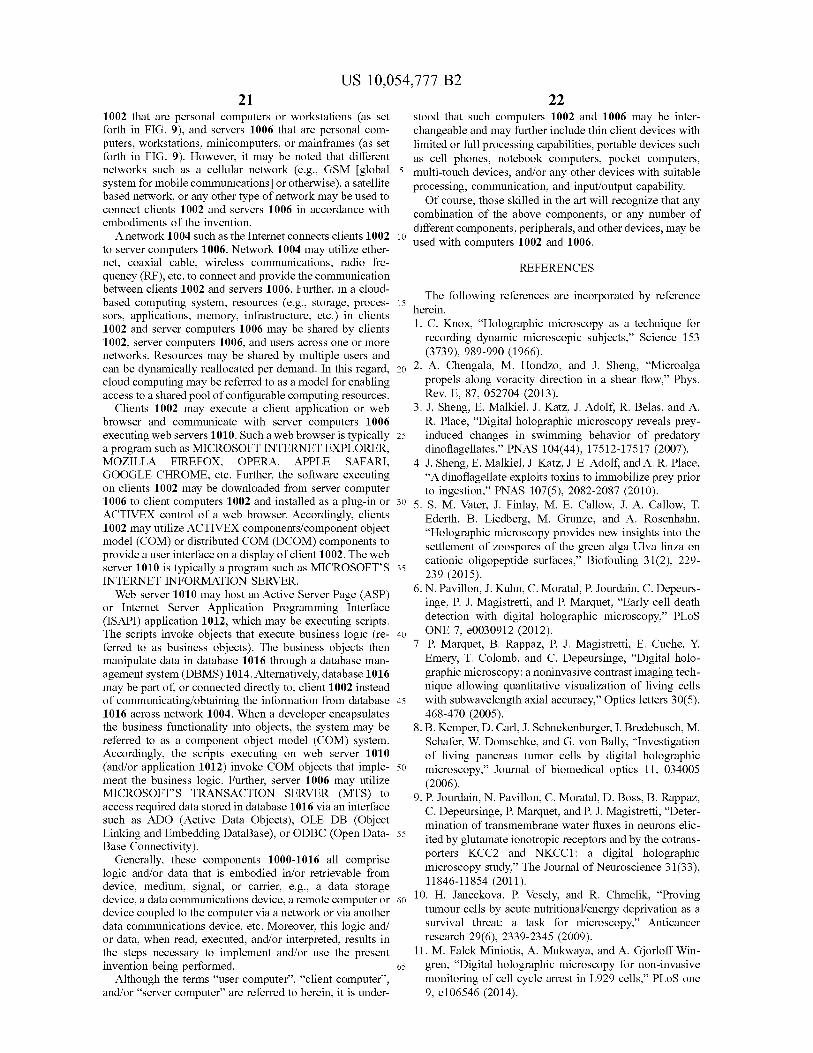
US 10,054,777 B221
1002 that are personal computers or workstations (as setforth in FIG. 9), and servers 1006 that are personal com-puters, workstations, minicomputers, or mainframes (as setforth in FIG. 9). However, it may be noted that differentnetworks such as a cellular network (e.g., GSM [globalsystem for mobile communications] or otherwise), a satellitebased network, or any other type of network may be used toconnect clients 1002 and servers 1006 in accordance withembodiments of the invention.A network 1004 such as the Internet connects clients 1002
to server computers 1006. Network 1004 may utilize ether-net, coaxial cable, wireless communications, radio fre-quency (RF), etc. to connect and provide the communicationbetween clients 1002 and servers 1006. Further, in a cloud-based computing system, resources (e.g., storage, proces-sors, applications, memory, infrastructure, etc.) in clients1002 and server computers 1006 may be shared by clients1002, server computers 1006, and users across one or morenetworks. Resources may be shared by multiple users andcan be dynamically reallocated per demand. In this regard,cloud computing may be referred to as a model for enablingaccess to a shared pool of configurable computing resources.
Clients 1002 may execute a client application or webbrowser and communicate with server computers 1006executing web servers 1010. Such a web browser is typicallya program such as MICROSOFT INTERNET EXPLORER,MOZILLA FIREFOX, OPERA, APPLE SAFARI,GOOGLE CHROME, etc. Further, the software executingon clients 1002 may be downloaded from server computer1006 to client computers 1002 and installed as a plug-in orACTIVEX control of a web browser. Accordingly, clients1002 may utilize ACTIVEX components/component objectmodel (COM) or distributed COM (DCOM) components toprovide a user interface on a display of client 1002. The webserver 1010 is typically a program such as MICROSOFT'SINTERNET INFORMATION SERVER.Web server 1010 may host an Active Server Page (ASP)
or Internet Server Application Programming Interface(ISAPI) application 1012, which may be executing scripts.The scripts invoke objects that execute business logic (re-ferred to as business objects). The business objects thenmanipulate data in database 1016 through a database man-agement system (DBMS)1014. Alternatively, database 1016may be part of, or connected directly to, client 1002 insteadof communicating/obtaining the information from database1016 across network 1004. When a developer encapsulatesthe business functionality into objects, the system may bereferred to as a component object model (COM) system.Accordingly, the scripts executing on web server 1010(and/or application 1012) invoke COM objects that imple-ment the business logic. Further, server 1006 may utilizeMICROSOFT'S TRANSACTION SERVER (MTS) toaccess required data stored in database 1016 via an interfacesuch as ADO (Active Data Objects), OLE DB (ObjectLinking and Embedding DataBase), or ODBC (Open Data-Base Connectivity).
Generally, these components 1000-1016 all compriselogic and/or data that is embodied in/or retrievable fromdevice, medium, signal, or carrier, e.g., a data storagedevice, a data communications device, a remote computer ordevice coupled to the computer via a network or via anotherdata communications device, etc. Moreover, this logic and/or data, when read, executed, and/or interpreted, results inthe steps necessary to implement and/or use the presentinvention being performed.
Although the terms "user computer", "client computer",and/or "server computer" are referred to herein, it is under-
22stood that such computers 1002 and 1006 may be inter-changeable and may further include thin client devices withlimited or full processing capabilities, portable devices suchas cell phones, notebook computers, pocket computers,
5 multi-touch devices, and/or any other devices with suitableprocessing, communication, and input/output capability.Of course, those skilled in the art will recognize that any
combination of the above components, or any number ofdifferent components, peripherals, and other devices, may be
to used with computers 1002 and 1006.
REFERENCES
15 The following references are incorporated by reference
herein.I. C. Knox, "Holographic microscopy as a technique for
recording dynamic microscopic subjects," Science 153(3739), 989-990 (1966).
20 2. A. Chengala, M. Hondzo, and J. Sheng, "Microalgapropels along voracity direction in a shear flow," Phys.Rev. E, 87, 052704 (2013).
3. J. Sheng, E. Malkiel, J. Katz, J. Adolf, R. Belas, and A.R. Place, "Digital holographic microscopy reveals prey-
25 induced changes in swimming behavior of predatorydinoflagellates," PNAS 104(44), 17512-17517 (2007).
4. J. Sheng, E. Malkiel, J. Katz, J. E. Adolf, and A. R. Place,"A dinoflagellate exploits toxins to immobilize prey priorto ingestion," PNAS 107(5), 2082-2087 (2010).
30 5. S. M. Vater, J. Finlay, M. E. Callow, J. A. Callow, T.Ederth, B. Liedberg, M. Grunze, and A. Rosenhahn,"Holographic microscopy provides new insights into thesettlement of zoospores of the green alga Ulva linza oncationic oligopeptide surfaces," Biofouling 31(2), 229-
35 239 (2015).
6. N. Pavillon, J. Kuhn, C. Moratal, P. Jourdain, C. Depeurs-inge, P. J. Magistretti, and P. Marquet, "Early cell deathdetection with digital holographic microscopy," PLoS
40 ONE 7, e0030912 (2012).7. P. Marquet, B. Rappaz, P. J. Magistretti, E. Cuche, Y.
Emery, T. Colomb, and C. Depeursinge, "Digital holo-graphic microscopy: a noninvasive contrast imaging tech-nique allowing quantitative visualization of living cells
45 with subwavelength axial accuracy," Optics letters 30(5),468-470 (2005).
8. B. Kemper, D. Carl, J. Schnekenburger, I. Bredebusch, M.Schafer, W. Domschke, and G. von Bally, "Investigationof living pancreas tumor cells by digital holographic
50 microscopy," Journal of biomedical optics 11, 034005(2006).
9. P. Jourdain, N. Pavillon, C. Moratal, D. Boss, B. Rappaz,C. Depeursinge, P. Marquet, and P. J. Magistretti, "Deter-mination of transmembrane water fluxes in neurons elic-
55 ited by glutamate ionotropic receptors and by the cotrans-porters KCC2 and NKCCI: a digital holographicmicroscopy study," The Journal of Neuroscience 31(33),11846-11854 (2011).
60 10. H. Janeckova, P. Vesely, and R. Chmelik, "Provingtumour cells by acute nutritional/energy deprivation as asurvival threat: a task for microscopy," Anticancerresearch 29(6), 2339-2345 (2009).
11. M. Falck Miniotis, A. Mukwaya, and A. Gjorloff Win-65 gren, "Digital holographic microscopy for non-invasive
monitoring of cell cycle arrest in L929 cells," PLoS one9, e106546 (2014).
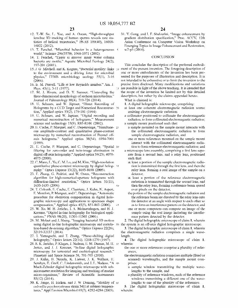
US 10,054,777 B2
2312. T.-W. Su, L. Xue, and A. Ozcan, "High-throughput
lensfree 3D tracking of human sperms reveals rare sta-tistics of helical trajectories," PNAS 109(40), 16018-16022 (2012).
13. T. Fenchel, "Microbial behavior in a heterogeneousworld," Science 296(5570), 1068-1071 (2002).
14. T. Fenchel, "Eppur si muove: many water columnbacteria are motile," Aquatic Microbial Ecology 24(2),197-201 (2001).
15. J. G. Mitchell, and K. Kogure, ̀Bacterial motility: linksto the environment and a driving force for microbialphysics," FEMS microbiology ecology 55(1), 3-16(2006).
16. E. M. Purcell, "Life at low Reynolds number," Am. J.Phys. 45(1), 3-11 (1977).
17. M. J. Rivera, and D. Y. Sumner, "Unraveling thethree-dimensional morphology of archean microbialites,"Journal of Paleontology 88(4), 719-726 (2014).
18. U. Schnars, and W. Jiiptner, "Direct Recording ofHolograms by a CCD Target and Numerical Reconstruc-tion," Applied optics 33(2), 179-181 (1994).
19. U. Schnars, and W. Juptner, "Digital recording andnumerical reconstruction of holograms," Measurementscience and technology 13(9), R85-R101 (2002).
20. E. Cuche, P. Marquet, and C. Depeursinge, "Simultane-ous amplitude-contrast and quantitative phase-contrastmicroscopy by numerical reconstruction of Fresnel off-axis holograms," Applied optics 38(34), 6994-7001(1999).
21. E. Cuche, P. Marquet, and C. Depeursinge, "Spatialfiltering for zero-order and twin-image elimination indigital off-axis holography," Applied optics 39(23), 4070-4075 (2000).
22. C. Mann, L. Yu, C. M. Lo, and M. Kim, "High-resolutionquantitative phase-contrast microscopy by digital holog-raphy," Optics Express 13(22), 8693-8698 (2005).
23. F. Zhang, G. Pedrini, and W. Osten, "Reconstructionalgorithm for high-numerical-aperture holograms withdiffraction-limited resolution," Optics letters 31(11),1633-1635 (2006).
24. T. Colomb, E. Cuche, F. Charriere, J. Kuhn, N. Aspert,F. Montfort, P. Marquet, and C. Depeursinge, "Automaticprocedure for aberration compensation in digital holo-graphic microscopy and applications to specimen shapecompensation," Applied optics 45(5), 851-863 (2006).
25. W. Xu, M. H. Jericho, I. A. Meinertzhagen, and H. J.Kreuzer, "Digital in-line holography for biological appli-cations," PNAS 98(20), 11301-11305 (2001).
26. M. Molaei and J. Sheng, "Imaging bacterial 3D motionusing digital in-line holographic microscopy and correla-tion-based de-noising algorithm," Optics Express 22(26),32119-32137 (2014).
27. I. Yamaguchi, and T. Zhang, "Phase-shifting digitalholography," Optics letters 22(16), 1268-1270 (1997).
28. S. K. Jericho, P. Klages, J. Nadeau, E. M. Dumas, M. H.Jerico, and J. J. Kreuzer, "In-line digital holographicmicroscopy for terrestrial and exobiological research,"Planetary and Space Science 58, 701-705 (2010).
29. J. Kuhn, B. Niraula, K. Liewer, J. K. Wallace, E.Serabyn, E. Graff, C. Lindensmith, and J. L. Nadeau, "AMach-Zehnder digital holographic microscope with sub-micrometer resolution for imaging and tracking of marinemicro-organisms," Review of Scientific Instruments85(12) (2014).
30. K. Junge, H. Eicken, and J. W. Deming, "Motility ofcolwellia psychrerythraea strain 34H at subzero tempera-tures," Appl Environ Microbiol 69(7), 4282-4284 (2003).
ME31. Y. Gong, and I. F. Sbalzarini, "Image enhancement by
gradient distribution specification," Proc. ACCV, 12thAsian Conference on Computer Vision Workshop onEmerging Topics in Image Enhancement and Restoration,
5 w7-p3 (2014).
CONCLUSION
This concludes the description of the preferred embodi-
10 ment of the present invention. The foregoing description ofone or more embodiments of the invention has been pre-sented for the purposes of illustration and description. It isnot intended to be exhaustive or to limit the invention to theprecise form disclosed. Many modifications and variations
15 are possible in light of the above teaching. It is intended thatthe scope of the invention be limited not by this detaileddescription, but rather by the claims appended hereto.
What is claimed is:1. A digital holographic microscope, comprising:
20 at least one coherent electromagnetic radiation sourceemitting electromagnetic radiation;
a collimator positioned to collimate the electromagneticradiation, to form collimated electromagnetic radiation;
a sample mount positioned such that:25 a sample mounted on the sample mount interacts with
the collimated electromagnetic radiation to formsample electromagnetic radiation, and
one or more references mounted on the sample mountinteract with the collimated electromagnetic radia-
30 tion to form reference electromagnetic radiation; anda microscope lens assembly, comprising a first lens sepa-
rate from a second lens, and a relay lens, positionedsuch that:at least a portion of the sample electromagnetic radia-
35 tion is transmitted through the first lens, and then therelay lens, forming a real image of the sample on adetector,
at least a portion of the reference electromagneticradiation is transmitted through the second lens, and
40 then the relay lens, forming a reference beam spreadover pixels on the detector,
the portion of the sample electromagnetic radiation andthe reference beam are directed by the relay lens ontothe detector at an angle with respect to each other so
45 as to form an interference pattern on the detector, andone or more computers can compute an image of the
sample using the real image including the interfer-ence pattern detected by the detector.
2. The digital holographic microscope of claim 1, wherein50 the system is an off-axis digital holographic microscope.
3. The digital holographic microscope of claim 1, whereinthe electromagnetic radiation comprises a single wave-length.
4. The digital holographic microscope of claim 1,55 wherein:
the one or more references comprise a plurality of refer-ences,
the electromagnetic radiation comprises multiple (fixed orscanned) wavelengths, and the sample mount com-
60 prises:a sample window transmitting the multiple wave-
lengths to the sample, anda plurality of reference windows, each of the referencewindows transmitting a different one of the wave-
65 lengths to one of the plurality of the references.5. The digital holographic microscope of claim 1,
wherein:
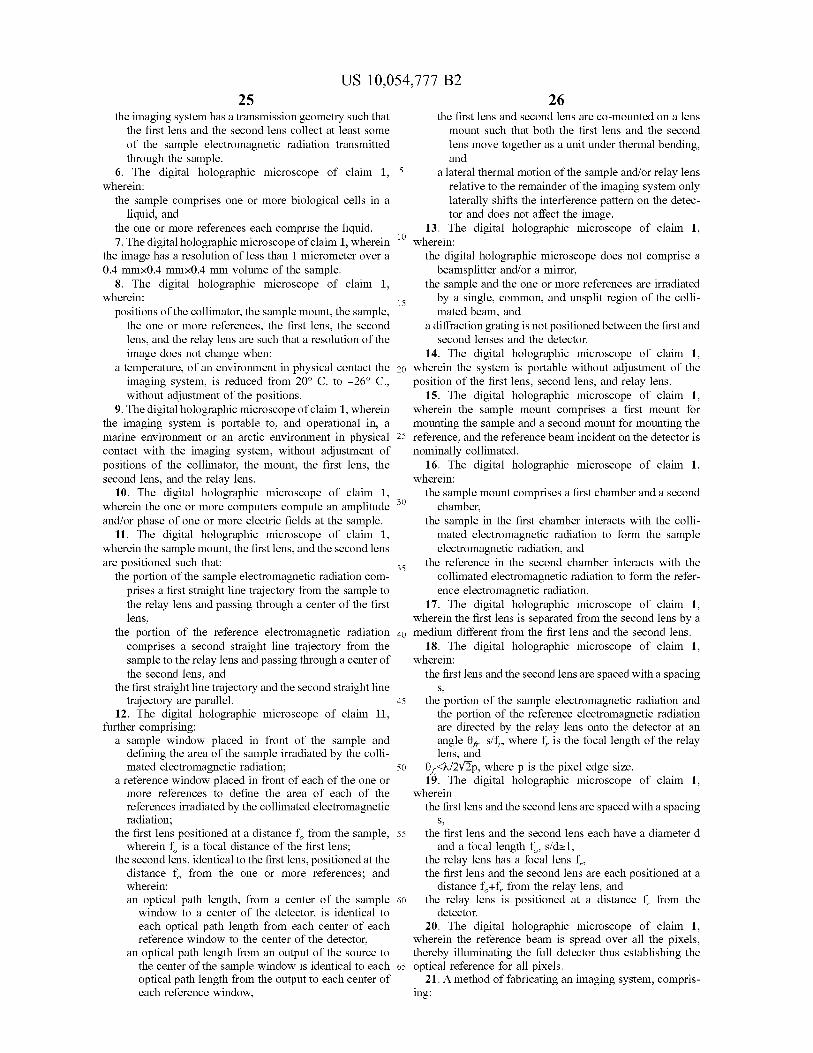
US 10,054,777 B2
25the imaging system has a transmission geometry such that
the first lens and the second lens collect at least someof the sample electromagnetic radiation transmittedthrough the sample.
6. The digital holographic microscope of claim 1, 5wherein:
the sample comprises one or more biological cells in aliquid, and
the one or more references each comprise the liquid.7. The digital holographic microscope of claim 1, wherein to
the image has a resolution of less than 1 micrometer over a0.4 mmx0.4 mmx0.4 mm volume of the sample.
8. The digital holographic microscope of claim 1,wherein:
15positions of the collimator, the sample mount, the sample,
the one or more references, the first lens, the secondlens, and the relay lens are such that a resolution of theimage does not change when:
a temperature, of an environment in physical contact the 20imaging system, is reduced from 20° C. to —26° C.,without adjustment of the positions.
9. The digital holographic microscope of claim 1, whereinthe imaging system is portable to, and operational in, amarine environment or an arctic environment in physical 25
contact with the imaging system, without adjustment ofpositions of the collimator, the mount, the first lens, thesecond lens, and the relay lens.
10. The digital holographic microscope of claim 1,wherein the one or more computers compute an amplitude 30
and/or phase of one or more electric fields at the sample.11. The digital holographic microscope of claim 1,
wherein the sample mount, the first lens, and the second lensare positioned such that: 35
the portion of the sample electromagnetic radiation com-prises a first straight line trajectory from the sample tothe relay lens and passing through a center of the firstlens,
the portion of the reference electromagnetic radiation 40comprises a second straight line trajectory from thesample to the relay lens and passing through a center ofthe second lens, and
the first straight line trajectory and the second straight linetrajectory are parallel. 45
12. The digital holographic microscope of claim 11,further comprising:
a sample window placed in front of the sample anddefining the area of the sample irradiated by the colli-mated electromagnetic radiation; 50
a reference window placed in front of each of the one ormore references to define the area of each of thereferences irradiated by the collimated electromagneticradiation;
the first lens positioned at a distance f from the sample, 55wherein f is a focal distance of the first lens;
the second lens, identical to the first lens, positioned at thedistance f from the one or more references; andwherein:an optical path length, from a center of the sample 60window to a center of the detector, is identical toeach optical path length from each center of eachreference window to the center of the detector,
an optical path length from an output of the source tothe center of the sample window is identical to each 65optical path length from the output to each center ofeach reference window,
26the first lens and second lens are co-mounted on a lensmount such that both the first lens and the secondlens move together as a unit under thermal bending,and
a lateral thermal motion of the sample and/or relay lensrelative to the remainder of the imaging system onlylaterally shifts the interference pattern on the detec-tor and does not affect the image.
13. The digital holographic microscope of claim 1,wherein:
the digital holographic microscope does not comprise abeamsplitter and/or a mirror,
the sample and the one or more references are irradiatedby a single, common, and unsplit region of the colli-mated beam, and
a diffraction grating is not positioned between the first andsecond lenses and the detector.
14. The digital holographic microscope of claim 1,wherein the system is portable without adjustment of theposition of the first lens, second lens, and relay lens.
15. The digital holographic microscope of claim 1,wherein the sample mount comprises a first mount formounting the sample and a second mount for mounting thereference, and the reference beam incident on the detector isnominally collimated.
16. The digital holographic microscope of claim 1,wherein:
the sample mount comprises a first chamber and a secondchamber,
the sample in the first chamber interacts with the colli-mated electromagnetic radiation to form the sampleelectromagnetic radiation, and
the reference in the second chamber interacts with thecollimated electromagnetic radiation to form the refer-ence electromagnetic radiation.
17. The digital holographic microscope of claim 1,wherein the first lens is separated from the second lens by amedium different from the first lens and the second lens.
18. The digital holographic microscope of claim 1,wherein:
the first lens and the second lens are spaced with a spacingS,
the portion of the sample electromagnetic radiation andthe portion of the reference electromagnetic radiationare directed by the relay lens onto the detector at anangle 0f,— s/f , where f is the focal length of the relaylens, and
0f<X/2V2p, where p is the pixel edge size.19. The digital holographic microscope of claim 1,
whereinthe first lens and the second lens are spaced with a spacing
S,
the first lens and the second lens each have a diameter dand a focal length f , s/d>-1,
the relay lens has a focal lens f ,the first lens and the second lens are each positioned at a
distance f +f from the relay lens, andthe relay lens is positioned at a distance f from the
detector.20. The digital holographic microscope of claim 1,
wherein the reference beam is spread over all the pixels,thereby illuminating the full detector thus establishing theoptical reference for all pixels.21. A method of fabricating an imaging system, compris-
ing:
US 10,054,777 B2
27 28providing a sample mount wherein:
a sample mounted on the sample mount interacts withcollimated electromagnetic radiation to form sampleelectromagnetic radiation, and
one or more references mounted on the sample mount sinteract with the collimated electromagnetic radia-tion to form reference electromagnetic radiation;
providing an assembly comprising a first objective sepa-rate from a second objective; and
providing an imaging system, wherein: 10
at least a portion of the sample electromagnetic radia-tion is transmitted through the first objective to theimaging system, the imaging system and the firstobjective forming a real image of the sample on asensor, 15
at least a portion of the reference electromagneticradiation is transmitted through the second objectiveto the imaging system, forming a reference beamspread over all pixels on the sensor and
the portion of the sample electromagnetic radiation and 20the portion of the reference electromagnetic radia-tion combine at the sensor in the imaging system soas to form an interference pattern.