us epa - alternative control techniques document … november 2007 alternative control techniques...
TRANSCRIPT

Alternative Control Techniques Document Update - NOx Emissions from New Cement Kilns


EPA-453/R-07-006 November 2007
Alternative Control Techniques Document Update – NOx Emissions from New Cement Kilns
By: Bill Neuffer, Project Officer Metals and Minerals Group
and
Mike Laney
Research Triangle Institute. Research Triangle Park, North Carolina
Contract No. EP-D-06-118 Work Assignment No. 1-22
U.S. Environmental Protection Agency Office of Air Quality Planning and Standards
Sector Policies and Programs Division Research Triangle Park, North Carolina

[This page intentionally left blank.]
iii
TABLE OF CONTENTS
1.0 INTRODUCTION/PURPOSE............................................................................................ 1 2.0 SUMMARY........................................................................................................................ 3
2.1 Process Description................................................................................................. 3 2.2 NOx Emissions from Preheater/Precalciner (PH/PC) Kilns.................................... 3 2.3 Factors Affecting NOx Emissions........................................................................... 3 2.4 Process controls that Reduce NOx Emissions......................................................... 4 2.5 Staged Combustion ................................................................................................. 5 2.6 Selective Noncatalytic Reduction (SNCR)............................................................. 5 2.7 Selective Catalytic Reduction (SCR)...................................................................... 7 2.8 Multipollutant Effects ............................................................................................. 9 2.9 Costs – SNCR and SCR........................................................................................ 10
3.0 PROCESS DESCRIPTION .............................................................................................. 11 3.1 Process Steps And Operations .............................................................................. 11 3.2 New Kilns ............................................................................................................. 12
3.2.1 Preheater ................................................................................................... 15 3.2.2 Calciner ..................................................................................................... 16 3.2.3 Rotary Kiln................................................................................................ 20 3.2.4 Alkali Bypass – PH/PC Kiln Systems ...................................................... 22
3.3 References............................................................................................................. 23 4.0 NOx EMISSIONS FROM PH/PC KILNS ........................................................................ 25
4.1 Thermal NOx......................................................................................................... 25 4.2 Fuel NOx
............................................................................................................... 27 4.3 Feed NOx .............................................................................................................. 28 4.4 Prompt NOx........................................................................................................... 28 4.5 References............................................................................................................. 28
5.0 FACTORS AFFECTING NOX EMISSIONS................................................................... 31 6.0 PROCESS CONTROLS THAT REDUCE NOX EMISSIONS........................................ 33
6.1 Combustion Zone Control of Temperature and Excess Air.................................. 33 6.2 Feed Mix Composition ......................................................................................... 33 6.3 Kiln Fuel ............................................................................................................... 34 6.4 Increasing Thermal Efficiency.............................................................................. 34 6.5 Staged Combustion in Kiln................................................................................... 34 6.6 Efficient Cooler Control ....................................................................................... 34 6.7 Expert Control Systems ........................................................................................ 35 6.8 Low NOx Burners (LNB) in Kiln.......................................................................... 35 6.9 References............................................................................................................. 36
7.0 STAGED COMBUSTION ............................................................................................... 37 7.1 Staged Combustion in the Calciner (SCC) Mechanism........................................ 37 7.2 Three Types of SCC.............................................................................................. 39
7.2.1 Staged-Air ................................................................................................. 39 7.2.2 Air and Fuel Staging ................................................................................. 40 7.2.3 Sequenced Fuel and Air ............................................................................ 41
iv
7.3 Summary of SCC NOx Performance..................................................................... 42 7.4 Limitations of Multistage Combustion (MSC) – High Sulfur .............................. 44 7.5 References............................................................................................................. 44
8.0 SELECTIVE NONCATALYTIC REDUCTION (SNCR)............................................... 47 8.1 Basis of SNCR ...................................................................................................... 47 8.2 Equipment Needed for SNCR............................................................................... 47 8.3 Appropriate Temperature for SNCR..................................................................... 48
8.3.1 Location of Suitable Temperature ............................................................ 49 8.4 Other Factors Affecting SNCR............................................................................. 50
8.4.1 Residence Time......................................................................................... 50 8.4.2 Degree of Mixing...................................................................................... 51 8.4.3 Uncontrolled NOx ..................................................................................... 51 8.4.4 Normalized Stoichiometric Ratio (NSR) .................................................. 52
8.5 Potential Problems with SNCR............................................................................. 53 8.6 SNCR Experience ................................................................................................. 54
8.6.1 United States – Early Tests ....................................................................... 54 8.6.2 U.S. Plants Presently Using or Installing SNCR ...................................... 57 8.6.3 SNCR – Foreign Experience – Europe, Japan, Taiwan ............................ 70
8.7 Summary of SNCR Performance.......................................................................... 72 8.8 References............................................................................................................. 73
9.0 MULTISTAGE COMBUSTION (MSC) AND SELECTIVE NONCATALYTIC REDUCTION (SNCR) ..................................................................................................... 79 9.1 References............................................................................................................. 82
10.0 SELECTIVE CATALYTIC REDUCTION (SCR) .......................................................... 85 10.1 Process Description............................................................................................... 85 10.2 Equipment Needed for SCR.................................................................................. 86 10.3 Early Pilot Tests.................................................................................................... 87
10.3.1 USA........................................................................................................... 87 10.3.2 Europe ....................................................................................................... 88
10.4 SCR Installations .................................................................................................. 88 10.4.1 Solnhofen – Germany ............................................................................... 88 10.4.2 Cementeria di Monselice – Italy ............................................................... 91 10.4.3 Italcementi Sarche di Calavino – Italy...................................................... 92
10.5 Issues/Solutions Using SCR at Cement Kilns ...................................................... 92 10.5.1 SO2 Oxidation ........................................................................................... 93 10.5.2 High CaO Loading and Potential Masking – CaSO4 Formation .............. 94 10.5.3 Ammonium Bisulfate................................................................................ 94 10.5.4 Water Soluble Alkali – Alkali Poisoning – Catalyst Deactivation ........... 94 10.5.5 Catalytic Deactivation Due to Catalyst Poisoning.................................... 95 10.5.6 Catalyst Plugging and Fouling Due to High Dust Loading and
Depositing of “Sticky Materials”.............................................................. 95 10.5.7 NOx Inlet Variability/NH3 Slip ................................................................. 96 10.5.8 Temperature-Related Factors Leading to Lower SCR NOx
Removal Efficiencies ................................................................................ 96 10.6 Developmental Technologies................................................................................ 97

v
10.7 References............................................................................................................. 97 11.0 MULTIPOLLUTANT ASPECTS OF SELECTIVE NONCATALYTIC
REDUCTION (SNCR) AND SELECTIVE CATALYTIC REDUCTION (SCR) ........ 101 11.1 References........................................................................................................... 102
12.0 SNCR AND SCR COSTS .............................................................................................. 103 12.1 References........................................................................................................... 115
APPENDIX A – Best Available Control Technology (BACT)/ Reasonably Available
Control Technology (RACT)/ Lowest Available Emission Rate (LAER) Determinations

vi
LIST OF TABLES
Table Page
2-1 Uncontrolled NOx Emissions (pounds per ton [lb/t]) by Kiln Type ................................... 4 2-2 Summary of NOx Performance of SCC .............................................................................. 5 2-3 SNCR Summary.................................................................................................................. 7 2-4 SCR Tests – Cementerie di Monselice ............................................................................... 9 2-5 Cost Effectiveness and Cost Burden of SNCR and SCR Systems ................................... 10 3-1 Cement Kiln Capacities (mt/yr) ........................................................................................ 13 3-2 Operating Conditions – PH/PC Kilns ............................................................................... 13 3-3 Heat Input by Cement Kiln Type...................................................................................... 13 6-1 Uncontrolled NOx Emissions (lb/t) – Cement Kilns......................................................... 36 7-1 Parameters Affecting NOx and Staged Combustion Responses ....................................... 38 7-2 NOx Emissions Performance of Selected Cement Plants ................................................. 43 7-3 Summary of NOx Performance of SCC ............................................................................ 44 8-1 Suitable Temperatures for SNCR ..................................................................................... 48 8-2 Summary of Pilot Test Results for Ash Grove and LaFarge ............................................ 57 8-3 NOx Reductions (%) for Lines at Holcim, Midlothian, Texas.......................................... 59 8-4 BACT Determinations – Suwannee American Cement, Branford, Florida, 11/05 .......... 67 8-5 Emission Test Results with Tires – Florida Rock Industries, Newberry, Florida,
12/04 ................................................................................................................................. 67 8-6 Emission Test Results without Tires – Florida Rock Industries, Newberry,
Florida, 12/04.................................................................................................................... 68 8-7 SNCR at a Taiwan Cement Plant...................................................................................... 72 8-8 SNCR Summary................................................................................................................ 73 9-1 Effect of SNCR on Emissions with Staged Combustion.................................................. 80 9-2 Impact of Injecting Ammonia in Burnout Zone ............................................................... 80 9-3 Impact of Injecting Ammonia in Reducing Zone ............................................................. 81 10-1 SCR Tests – 2006 – Cementerie di Monselice ................................................................. 91 11-1 Potential Multipollutant Effects of SNCR and SCR....................................................... 101 12-1 SNCR and SCR Costs for Preheater/Precalciner Kilns .................................................. 105 12-2 SNCR and SCR Costs for Preheater/Precalciner Kilns in 2005 Dollars ........................ 111
vii
LIST OF FIGURES
Figure Page
3-1 Primary operations – PH/PC kiln cement plant ................................................................ 11 3-2 Primary operations – PH/PC cement kiln plant ................................................................ 12 3-3 PH/PC kiln – Suwannee American Cement, Branford, Florida........................................ 14 3-4 PH/PC kiln system. ........................................................................................................... 14 3-5 F.L. Schmidt ILC kiln system........................................................................................... 18 3-6 F.L. Schmidt SLC with single-string preheater ................................................................ 19 3-7 F.L. Schmidt SLC with dual-string preheater................................................................... 20 4-1 NO vs. temperature at various O2 levels........................................................................... 26 7-1 Principle of NOx reduction by SCC.................................................................................. 38 7-2 Suwannee American Cement, Branford, Florida, staged-air SCC.................................... 39 7-3 Suwannee American, Branford, Florida, Polysius MSC – SCC with kiln inlet
burner ................................................................................................................................ 40 7-4 Florida Rock Industries, Newberry, Florida, air and fuel staging – SCC......................... 40 7-5 Titan America, Medley, Florida, sequenced fuel and air – SCC ...................................... 41 8-1 Ammonia and urea reduction at various temperatures ..................................................... 49 8-2 Possible SNCR injection points ........................................................................................ 50 8-3 NOx reduction and residence time .................................................................................... 51 8-4 Effect of initial NOx level on reduction efficiency ........................................................... 52 8-5 Impact of Normalized Stoichiometric Ratio on NOx reduction........................................ 53 8-6 Suwannee American Cement – Branford, Florida. ........................................................... 62 8-7 SNCR injection location – Suwannee American Cement, Branford, Florida................... 63 8-8 Ammonia injection, Suwannee American Cement. .......................................................... 64 8-9 Suwannee American Cement ammonia injection nozzle.................................................. 65 9-1 NH3 injection – burnout zone............................................................................................ 80 9-2 NH3 injection – reducing zone .......................................................................................... 81 10-1 SCR system adjacent to preheater tower at Solnhofen Portland cement plant ................. 87

viii
[This page intentionally left blank.]

1
1.0 INTRODUCTION/PURPOSE
This report addresses nitrogen oxides (NOx) controls for new cement kilns and focuses specifically on staged combustion in the calciner (SCC), selective noncatalytic reduction (SNCR), and selective catalytic reduction (SCR) as processes for the control of NOx. Practices and controls that are incorporated in normal operating processes for cement kilns will also be discussed. Previous EPA documents on NOx controls for cement kilns include Alternative Control Techniques Document - NOx Emissions from Cement Manufacturing, dated March 1994 (EPA-453/R-94-004) and available online at www.epa.gov/ttn/catc/dir1/cement.pdf, and NOx Control Technologies for the Cement Industry, dated September 19, 2000, and available online at www.epa.gov/ttn/naaqs/ozone/ozonetech/cement_nox_update_09152000.pdf.
This report summarizes information controls for new cement kilns; therefore, this document addresses only preheater/precalciner (PH/PC) cement kilns because these are the only type of kiln expected to be built in the future. For details on the other kiln types (e.g., wet kilns and long dry kilns) and their NOx controls, please review the two EPA documents mentioned above.
This report is organized as follows:
Chapter 2 Summary Chapter 3 Process Description Chapter 4 NOx Emissions from PH/PC Cement Kilns Chapter 5 Factors Affecting NOx Emissions Chapter 6 Process Controls that Reduce NOx Emissions Chapter 7 Staged Combustion Chapter 8 Selective Noncatalytic Reduction (SNCR) Chapter 9 Multistage Combustion (MSC) and Selective Noncatalytic
Reduction (SNCR) Chapter 10 Selective Catalytic Reduction Chapter 11 Multipollutant Aspects of SNCR and SCR Chapter 12 SNCR and SCR Costs
Other technologies for lowering NOx emissions from new cement kilns have been discussed in other documents. However, these technologies have not been demonstrated for any cement kiln. For example, NOx oxidation (LoTOxTM) technology has been considered as a control. Additional information on this and other technologies not discussed in this report can be found at the following Web sites:
http://seca.doe.gov/publications/proceedings/00/scr00/ANDERSON.PDF http://www.tceq.state.tx.us/implementation/air/sip/BSA_settle.html http://files.harc.edu/Projects/AirQuality/Projects/H028.DFW.2004/H28DFWExecutiv
eSummary.pdf

2
[This page intentionally left blank.]
3
2.0 SUMMARY
This section summarizes the information contained in this report. The reader is encouraged to read the complete chapters to obtain a more thorough understanding.
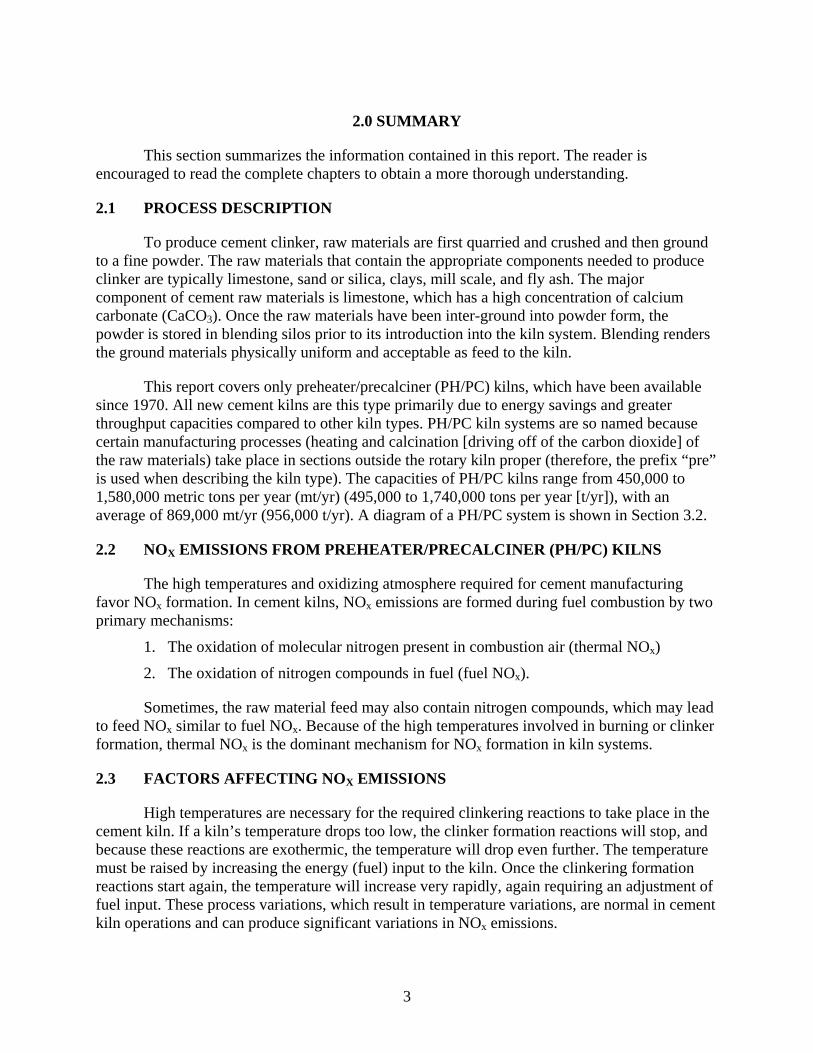
2.1 PROCESS DESCRIPTION
To produce cement clinker, raw materials are first quarried and crushed and then ground to a fine powder. The raw materials that contain the appropriate components needed to produce clinker are typically limestone, sand or silica, clays, mill scale, and fly ash. The major component of cement raw materials is limestone, which has a high concentration of calcium carbonate (CaCO3). Once the raw materials have been inter-ground into powder form, the powder is stored in blending silos prior to its introduction into the kiln system. Blending renders the ground materials physically uniform and acceptable as feed to the kiln.
This report covers only preheater/precalciner (PH/PC) kilns, which have been available since 1970. All new cement kilns are this type primarily due to energy savings and greater throughput capacities compared to other kiln types. PH/PC kiln systems are so named because certain manufacturing processes (heating and calcination [driving off of the carbon dioxide] of the raw materials) take place in sections outside the rotary kiln proper (therefore, the prefix “pre” is used when describing the kiln type). The capacities of PH/PC kilns range from 450,000 to 1,580,000 metric tons per year (mt/yr) (495,000 to 1,740,000 tons per year [t/yr]), with an average of 869,000 mt/yr (956,000 t/yr). A diagram of a PH/PC system is shown in Section 3.2.
2.2 NOX EMISSIONS FROM PREHEATER/PRECALCINER (PH/PC) KILNS
The high temperatures and oxidizing atmosphere required for cement manufacturing favor NOx formation. In cement kilns, NOx emissions are formed during fuel combustion by two primary mechanisms:
1. The oxidation of molecular nitrogen present in combustion air (thermal NOx)
2. The oxidation of nitrogen compounds in fuel (fuel NOx).
Sometimes, the raw material feed may also contain nitrogen compounds, which may lead to feed NOx similar to fuel NOx. Because of the high temperatures involved in burning or clinker formation, thermal NOx is the dominant mechanism for NOx formation in kiln systems.
2.3 FACTORS AFFECTING NOX EMISSIONS
High temperatures are necessary for the required clinkering reactions to take place in the cement kiln. If a kiln’s temperature drops too low, the clinker formation reactions will stop, and because these reactions are exothermic, the temperature will drop even further. The temperature must be raised by increasing the energy (fuel) input to the kiln. Once the clinkering formation reactions start again, the temperature will increase very rapidly, again requiring an adjustment of fuel input. These process variations, which result in temperature variations, are normal in cement kiln operations and can produce significant variations in NOx emissions.
4
The kiln flame temperature is higher for gas burners than for coal burners as the flame temperature is higher for gas combustion than for coal combustion. By far, coal is the predominant fuel used in cement kilns. In addition to temperature variations that can initiate thermal NOx formation, fuels with higher nitrogen content will have more nitrogen available for fuel NOx formation. Changes in the feed rate, chemical composition, or moisture content of raw materials can also change a kiln’s operating parameters.
2.4 PROCESS CONTROLS THAT REDUCE NOX EMISSIONS
The primary goal of process controls is to stabilize process parameters and kiln conditions. The process controls used to stabilize kiln operations also improve energy efficiency by reducing heat consumption, improve clinker quality, and increase the life of the cement plant. Another beneficial effect of process controls is the reduction of NOx emissions because of improved fuel efficiency.
When determining uncontrolled NOx emissions, the following standard operating practice (SOP) components should be considered. These SOPs are incorporated by all new PH/PC kiln systems.
Combustion zone control of temperature and excess air through continuous monitoring of temperature and excess air
Feed mix composition Kiln fuel type Increased thermal efficiency Staged combustion in kiln Efficient cooler control Expert control systems Low NOx burners in the kiln.
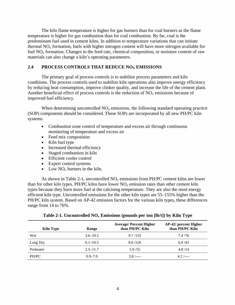
As shown in Table 2-1, uncontrolled NOx emissions from PH/PC cement kilns are lower than for other kiln types. PH/PC kilns have lower NOx emission rates than other cement kiln types because they burn more fuel at the calcining temperature. They are also the most energy efficient kiln type. Uncontrolled emissions for the other kiln types are 55–155% higher than the PH/PC kiln system. Based on AP-42 emission factors for the various kiln types, these differences range from 14 to 76%.
Table 2-1. Uncontrolled NOx Emissions (pounds per ton [lb/t]) by Kiln Type
Kiln Type Range Average/ Percent Higher
than PH/PC Kiln AP-42/ percent Higher
than PH/PC Kiln
Wet 3.6–19.5 9.7 /155 7.4 /76
Long Dry 6.1–10.5 8.6 /126 6.0 /43
Preheater 2.5–11.7 5.9 /55 4.8 /14
PH/PC 0.9–7.0 3.8 /---- 4.2 /----

5
2.5 STAGED COMBUSTION
There are many ways a PH/PC kiln system is considered to be using staged combustion (SC). The processes of the PH/PC kiln system itself, which include the drying, calcining, and sintering of the raw materials, can be considered SC. Also, a kiln with a multi-channel main kiln burner with indirect firing incorporates SC. All calciners have some degree of SC. The use of low NOx calciners, which inject fuel near the kiln inlet, is a form of SC. Staged combustion as discussed in this report refers to SC in the calciner (SCC).
SCC works by staging the introduction of fuel, combustion air, and feed material in a manner to minimize NOx formation and reduce NOx to nitrogen. NOx formed in the kiln’s combustion zone is chemically reduced by maintaining a reducing atmosphere at the kiln feed end by firing fuel in this region. The reducing atmosphere is maintained in the calciner region by controlling combustion air such that the calcining fuel is first burned under reducing conditions to reduce NOx and then burned under oxidizing conditions to complete the combustion reaction. Controlling the introduction of raw meal allows for control of the calciner temperature. Through these mechanisms, both fuel NOx and thermal NOx are controlled. The combustion chamber allows for improved control over the introduction of tertiary air in the calciner region, which helps to promote the proper reducing environment for NOx control.
The performance at U.S. kilns of SCC in controlling NOx is summarized in Table 2-2. Levels of NOx from PH/PC kilns using SCC range from1.4 to 3.3 lb NOx/t of clinker, with an average of approximately 2.5 lb/t of clinker.
Table 2-2. Summary of NOx Performance of SCC in U.S. Kilns
2.6 SELECTIVE NONCATALYTIC REDUCTION (SNCR)
The SNCR process is basically the injection of ammonia in the form of ammonia water or urea in the flue-gas at a suitable temperature. An ammonia solution (~20%) is the reagent that
Source/Location
NOx Uncontrolled
(lb/t) NOx Controlled (lb/t) Efficiency
11 US kilns(from Table 7-2) NA 2.2–3.3 (avg. 2.7) NA
Florida Rock 3.5 3.0 -w/o tires 1.5–2.5 (midpoint 2.0) –w/ tires
17% -w/o tires 43% -w/ tires
Suwannee American NA 2.2–2.6 (range) (midpoint 2.4)
NA
Titan American NA 2.0 NA
Lone Star 2.8 1.8 35%
Cemex Santa Cruz NA 2.5 (0% coal to reducing zone) 1.7 (50% coal to reducing zone)
1.4 (100% coal to reducing zone) (midpoint 1.8)
NA

6
has been most often used for cement kilns, and experience indicates that an ammonia solution is most effective for PH/PC cement kiln applications.
An SNCR system’s performance depends on temperature, residence time, turbulence, oxygen content, and a number of factors specific to the given gas stream. These factors are discussed later in this report. SNCR removes NOx by a two-step process, as follows:
4 NO + 4 NH3 + O2 4 N2 + 6 H2O
and
4 NH3 + 2 NO2 + O2 3 N2 + 6 H2O
The first equation is the predominant reaction because 90–95% of NOx in flue gas is NO.
Onsite storage vessels and a truck-unloading stand are required to receive the delivery of ammonia or urea to a plant. Ammonia and urea may be received as a liquid solution or may be mixed with water onsite to the desired solution concentration. If mixed onsite, additional water storage, purification, pumping, and mixing equipment is required. The purification system removes minerals from the water that may cause plugging of the ammonia delivery system. Ammonia, in the form of anhydrous ammonia gas, must be stored in cylinders. All forms of ammonia have specific transportation, handling, and storage requirements.
The ammonia solution is pumped through pipes and delivered into the precalciner or preheater tower through an injection lance. This injection process requires a pump, pump skid, and ammonia-flow control unit. The exact location and number of injection points will differ from one system to the next and is optimized through testing. Measurement equipment is necessary to maintain the appropriate ammonia feed rate. Additional monitoring equipment is required to record the amount of NOx and ammonia slip in the gases exiting the SNCR system to adjust the amount of ammonia entering the system. Temperature monitors are also required to make sure that the ammonia is delivered to the correct location.
Important design and operational factors that affect NOx reduction by an SNCR system are the following:
Residence time available in optimum temperature range Degree of mixing between injected reagent and combustion gases Uncontrolled NOx concentration level Molar ratio of injected reagent to uncontrolled NOx.
Further adjustments to SNCR can be employed under certain conditions, such as less aggressive versions of SCC (higher controlled baseline), raw material NH3 or sulfur, and high petcoke use. These adjustments can include such measures as multi-level reagent injection and fine hydrated lime mist injection in the conditioning tower. With NOx emission levels of 2.2 lb/t achievable with SCC, the addition of SNCR has the potential to lower emissions at an NSR of 0.5.
7
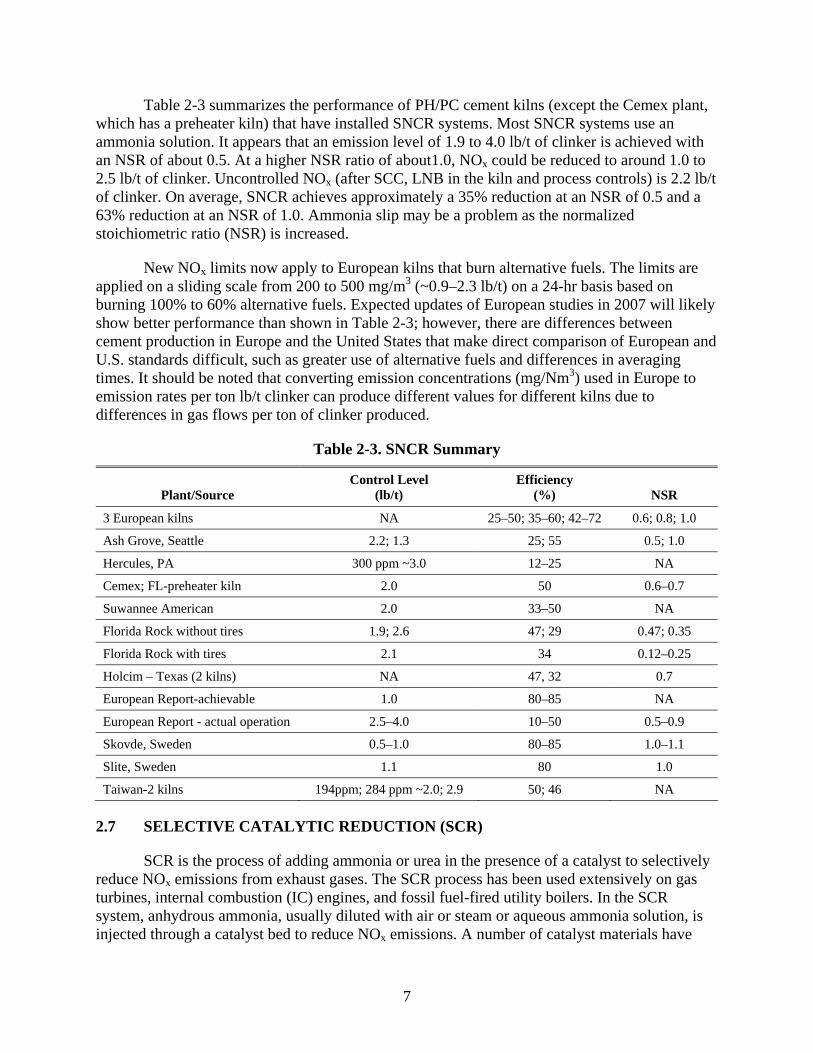
Table 2-3 summarizes the performance of PH/PC cement kilns (except the Cemex plant, which has a preheater kiln) that have installed SNCR systems. Most SNCR systems use an ammonia solution. It appears that an emission level of 1.9 to 4.0 lb/t of clinker is achieved with an NSR of about 0.5. At a higher NSR ratio of about1.0, NOx could be reduced to around 1.0 to 2.5 lb/t of clinker. Uncontrolled NOx (after SCC, LNB in the kiln and process controls) is 2.2 lb/t of clinker. On average, SNCR achieves approximately a 35% reduction at an NSR of 0.5 and a 63% reduction at an NSR of 1.0. Ammonia slip may be a problem as the normalized stoichiometric ratio (NSR) is increased.
New NOx limits now apply to European kilns that burn alternative fuels. The limits are applied on a sliding scale from 200 to 500 mg/m3 (~0.9–2.3 lb/t) on a 24-hr basis based on burning 100% to 60% alternative fuels. Expected updates of European studies in 2007 will likely show better performance than shown in Table 2-3; however, there are differences between cement production in Europe and the United States that make direct comparison of European and U.S. standards difficult, such as greater use of alternative fuels and differences in averaging times. It should be noted that converting emission concentrations (mg/Nm3) used in Europe to emission rates per ton lb/t clinker can produce different values for different kilns due to differences in gas flows per ton of clinker produced.
Table 2-3. SNCR Summary
Plant/Source Control Level
(lb/t) Efficiency
(%) NSR
3 European kilns NA 25–50; 35–60; 42–72 0.6; 0.8; 1.0
Ash Grove, Seattle 2.2; 1.3 25; 55 0.5; 1.0
Hercules, PA 300 ppm ~3.0 12–25 NA
Cemex; FL-preheater kiln 2.0 50 0.6–0.7
Suwannee American 2.0 33–50 NA
Florida Rock without tires 1.9; 2.6 47; 29 0.47; 0.35
Florida Rock with tires 2.1 34 0.12–0.25
Holcim – Texas (2 kilns) NA 47, 32 0.7
European Report-achievable 1.0 80–85 NA
European Report - actual operation 2.5–4.0 10–50 0.5–0.9
Skovde, Sweden 0.5–1.0 80–85 1.0–1.1
Slite, Sweden 1.1 80 1.0
Taiwan-2 kilns 194ppm; 284 ppm ~2.0; 2.9 50; 46 NA
2.7 SELECTIVE CATALYTIC REDUCTION (SCR)
SCR is the process of adding ammonia or urea in the presence of a catalyst to selectively reduce NOx emissions from exhaust gases. The SCR process has been used extensively on gas turbines, internal combustion (IC) engines, and fossil fuel-fired utility boilers. In the SCR system, anhydrous ammonia, usually diluted with air or steam or aqueous ammonia solution, is injected through a catalyst bed to reduce NOx emissions. A number of catalyst materials have

8
been used, such as titanium dioxide, vanadium pentoxide, and zeolite-based materials. The catalyst is typically supported on ceramic materials (e.g., alumina in a honeycomb monolith form) and promotes the NOx reduction reactions by providing a site for these reactions to occur. The catalyst is not consumed in the process, but allows the reactions to occur at a lower temperature.
The optimum temperature for the catalyst reactions depends on the specific catalyst used. Several different catalysts are available for use at different exhaust gas temperatures. Base metal catalysts are useful between 450 °F and 800 °F (232 °C and 427 °C). For high temperature operations (675 °F [357 °C] to over 1100 °F [593 °C] ), zeolite catalysts containing precious metals such as platinum and palladium are useful. The two principal reactions in the SCR process at cement plants using SCR are the following:
4 NH3+ 4 NO + O2 4 N2 + 6 H2O
and
4 NH3 + 2 NO2 + O2 3 N2 + 6 H2O
The first equation is the predominant reaction because90-95% of NOx in flue gas is NO.
It is important to note that the desired chemical reactions are identical with SNCR and SCR. The only difference is that a catalyst is present with SCR, which allows the reactions to occur at a lower temperature.
In an SCR system, ammonia is typically injected to produce a NH3: NOx molar ratio of 1.05–1.1:1 to achieve a NOx conversion of 80–90% with an ammonia slip of about 10 ppm of unreacted ammonia in gases leaving the reactor. The NOx removal efficiency depends on the flue gas temperature, the molar ratio of ammonia to NOx, and the flue gas residence time in the catalyst bed. All these factors must be considered in designing the desired NOx reduction, the appropriate reagent ratios, the catalyst bed volume, and the operating conditions. As with SNCR, the appropriate temperature window must be maintained to assure that ammonia slip does not result in a visible plume.
SCR can be installed at a cement kiln at two possible locations:
After the PM control device – a “low-dust” system After the last cyclone without ducting – a “high-dust” system.
The advantages of a “low-dust” system are longer catalyst life and lower danger of blockage. The disadvantage is the additional energy costs required to heat the cooled exhaust to achieve proper reaction temperatures in the catalyst.
On a worldwide basis, three cement kilns have used SCR: Solnhofen Zementwerkes in Germany and Cementeria di Monselice and Italcementi Sarche di Calavino in Italy. The SCR system was operated at the Solnhofen plant from 2001 to January 2006, at which time the plant began using SNCR to compare the operational costs of the two systems to evaluate which technology is better and more economical. Both Solnhofen and Cementeria di Monselice have

9
preheater kilns. The Italcementi plant operates a small Polysius Lepol technology kiln, which is a traveling grate preheater kiln. A picture of the Solnhofen installation is shown in section 10.4.
Both plants use a 25% aqueous ammonia solution, have 6 catalyst layers but only use 3 layers. Both plants have similar designs and facilities that are similar in size and raw materials.
At Solnhofen, 200 mg/m3 (~ 0.8 lb/t) of NOx is typically achieved from an inlet of 1,050 mg/Nm3 (4.2 lb/t) or 80% control. Also, ammonia slip was less than 1 mg/m3. Greater than 80% control is frequently achieved. At the end of 2003, the catalyst had logged 20,000–25,000 hours with no discernable problems. The catalyst was guaranteed for 16,000 hrs, with an expected catalyst life of 3–4 yrs.
The SCR system at Cementeria di Monselice in Bergamo, Italy began operation in June 2006. Catalyst activity remains high after 3,500 hours of operation. Following startup in June 2006, continuous testing was conducted for six weeks. The results of these tests are summarized in Table 2-4. As shown here, NOx reduction was 95 % at molar ratio of 0.89 and 43 % at molar ratio of 0.2. The facility operates at 400 mg NOx/Nm3.
Table 2-4. SCR Tests – Cementerie di Monselice
Parameter Units Design Actual*
Kiln capacity t/day 2,400 1,800
Gas flow m3/h norm; wet 160,000 110,000
NOx inlet mg/dscm 2,260 1,530/1,070
Molar ratio NH3/NOx 0.905 0.89/0.2
NOx outlet mg/dscm @ actual O2 232 75/612
NOx removal percent 90 95/43
NH3 slip mg/dscm < 5 < 1/< 1
NH4OH 25 percent solution; kg/h 445 204/34
* Two separate sets of data were collected for most parameters.
2.8 MULTIPOLLUTANT EFFECTS
The impacts of using SNCR and SCR controls on other pollutants can depend on the specific installation, including the nature of raw materials, kiln design and operating conditions. In general, for SNCR, emissions of NH3, N2O, CO, CO2, and PM10 may increase. For SCR, PM10 emissions may increase. Ammonia emissions may increase but not as much as for SNCR. In systems with higher SO2 emissions due to high sulfur content of raw materials, the conversion to SO3 by SCR can cause the additional effects of either sticky depostis or acid formation. For SCR, emissions of CO, H2SO4, Hg, VOC and dioxin/furan may decrease.

10
2.9 COSTS – SNCR AND SCR
Costs for SNCR and SCR controls on PH/PC kilns were obtained from a variety of sources at cement kilns in the U.S. and Europe. Some costs represent the cost of retrofitting existing kilns. To compare the cost information, the costs were scaled to 2005.
Capital costs for SNCR systems primarily include the cost of an injection system for the ammonia-based or urea-based reagent, the delivery system, reagent storage tanks, and control instrumentation. Operating costs include the costs of reagents and additives, electricity for reagent pumping, and fuel penalty cost, along with operating labor and maintenance requirements. The primary annual cost component is ammonia. Cost effectiveness and cost burden for SNCR systems are summarized in Table 2-5.
SCR systems applied to cement PH/PC kilns can be either “low-dust” or “high-dust” systems depending on their location after or before the particulate matter control device. In both types of systems, capital costs include the cost of the SCR catalyst and reactor, the costs to upgrade or replace kiln ID fans when SCR is added to existing PH/PC kilns, and, like the SNCR system, the costs of the reagent delivery system, storage, and instrumentation. Because of the problems of catalyst plugging, the high-dust system requires a catalyst cleaning mechanism, such as pressurized air nozzles or sonic horns. The low-dust system avoids costs associated with catalyst cleaning. Similar to SNCR, operating costs include operating labor and maintenance costs, reagent costs, and the electricity of reagent pumping. High-dust SCR systems incur higher energy costs for catalyst cleaning. Operating cost also include catalyst replacement every few years. Cost effectiveness and cost burden for SCR systems are summarized in Table 2-5.
Table 2-5. Cost Effectiveness and Cost Burden of SNCR and SCR Systems
Measure of Cost SNCR System SCR System
Cost Effectiveness ($/t NOx) Range Mean Median
330 to 5,200
1,700 1,200
480 to 22,000
4,200 1,800
Cost Burden ($/t of clinker) Range Mean Median
0.40 to 2.50
1.00 0.90
0.60 to 9.10
2.50 1.80

11
3.0 PROCESS DESCRIPTION
3.1 PROCESS STEPS AND OPERATIONS
To produce cement clinker, raw materials that contain oxides of calcium, silica, aluminum, and iron are first quarried and crushed and then inter-ground to a fine powder. The raw materials that contain the appropriate components needed to produce clinker are typically limestone, sand or silica, clays, mill scale, and fly ash. The major component of cement raw materials is limestone, which has a high concentration of calcium carbonate (CaCO3). This list only illustrates those raw materials that contain the compounds needed to produce clinker; however, almost any raw material in sufficient supply that contains one of the oxides mentioned above has the potential to be used in the cement manufacturing process. Once the raw materials have been inter-ground into powder form, the powder is stored in blending silos prior to its introduction into the kiln system. Blending renders the ground materials chemically uniform and acceptable as feed to the kiln (this raw material blend is typically called kiln feed or raw meal). Frequent analyses and quality control measures are necessary to ensure that raw materials are correctly proportioned during the manufacturing process because chemical uniformity of the feed to the kiln system is very important for stable kiln process operation.
Figure 3-1 depicts the primary operations of a typical PH/PC kiln system cement plant and the steps involved in producing cement. The initial step of quarrying and solid-fuel grinding is not shown in this figure. Figure 3-2 is a general flow diagram of a PH/PC kiln cement plant. Not all processes shown in the flow charts in Figure 3-2 will take place at all PH/PC plants; instead, the figure demonstrates all of the various processes that may be found at a typical new plant.
Figure 3-1. Primary operations – PH/PC kiln cement plant.1

12
More details on the overall cement production operations are provided in the two EPA documents mentioned in Section 1. An excellent virtual tour of a cement plant is available at the Portland Cement Association Web site (www.cement.org/basics/images/flashtour.html).
Figure 3-2. Primary operations – PH/PC cement kiln plant.2
3.2 NEW KILNS
This report covers only PH/PC kilns, which have been available since 1970. PH/PC kiln systems are so named because certain manufacturing processes (heating and calcination [driving off of the carbon dioxide] of the raw materials) take place in sections outside the rotary kiln proper (therefore, the prefix “pre” is used when describing the kiln type). The main reason why all new U.S. cement kiln systems are PH/PC kilns is because this kiln type has higher production capacities and greater fuel efficiency compared to other types of cement kilns. As shown in Table 3-1, the capacities of PH/PC kilns range from 450,000 to 1,580,000 mt/yr (495,000 to 1,740,000 t/yr), with an average of 869,000 mt/yr (956,000 t/yr).

13
Table 3-1. Cement Kiln Capacities (mt/yr)3
Kiln Type Range Average
Long wet 77,000–1,180,000 307,000
Long dry 50,000–590,000 265,000
Preheater 223,000–1,237,000 406,000
PH/PC 450,000–1,580,000 869,000
There are three distinct sections of the PH/PC kiln system, and the manufacturing processes that occur within these sections calcine most of the carbon dioxide (CO2) from the raw materials before they enter the kiln. The first section, the preheater, is a tower that consists of a series of cyclones and interconnecting ducts that dry and preheat the blended raw materials. The raw materials are then moved to the second section, the bottom of the preheater tower, to a special furnace called the calciner, or precalciner, which calcines the CO2 from the raw materials. The terms “calciner” and “precalciner” refer to the same process equipment and are used interchangeably throughout this document. Finally, the chemical reactions necessary to produce cement clinker in a PH/PC kiln cement plant occur in the section called the rotary kiln. A summary of the temperature profile ranges for the preheater, calciner, and rotary kiln of a PH/PC kiln plant, as well as the material retention time in these sections, is shown in Table 3-2.
Table 3-2. Operating Conditions – PH/PC Kilns4,5
Parameter Preheater Calciner Rotary Kiln
Gas temperature (°C) 350–950 850–1,200 1,200–2,000
Material temperature (°C) 200–750 800–900 1,200–1,550
Material retention time 2 minutes 2–4 seconds 30 minutes
Fuel is fired in two places in the PH/PC kiln system: the calciner and the discharge end of the rotary kiln. In other cement kiln systems, all thermal processes occur within the kiln. As a result, conventional kilns are much longer than PH/PC kilns as well as much less fuel efficient than PH/PC kiln types. Table 3-3 shows heat inputs in terms of million British Thermal Units (mmBtu)/t of clinker for various types of kilns. As the data clearly demonstrates, PH/PC kilns provide greater fuel efficiency.
Table 3-3. Heat Input by Cement Kiln Type6
Kiln Type Heat Input
(mmBtu/t of clinker) Percent Increase in Heat Input
Compared to PH/PC Heat Input
Long wet 6.0 45
Long dry 4.5 36
Preheater 3.8 15
PH/PC 3.3 -------
14
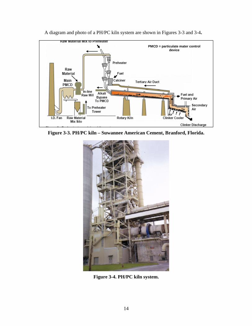
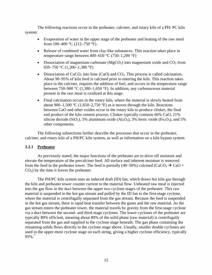
A diagram and photo of a PH/PC kiln system are shown in Figures 3-3 and 3-4.
PMCD = particulate mater control
device
Figure 3-3. PH/PC kiln – Suwannee American Cement, Branford, Florida.
Figure 3-4. PH/PC kiln system.
15
The following reactions occur in the preheater, calciner, and rotary kiln of a PH/ PC kiln system:
Evaporation of water in the upper stage of the preheater and heating of the raw meal from 100–400 °C (212–750 °F).
Release of combined water from clay-like substances. This reaction takes place in temperature range between 400–650 °C (750–1,200 °F)
Dissociation of magnesium carbonate (MgCO3) into magnesium oxide and CO2 from 650–750 °C (1,200–1,380 °F)
Dissociation of CaCO3 into lime (CaO) and CO2. This process is called calcination. About 90–95% of kiln feed is calcined prior to entering the kiln. This reaction takes place in the calciner, requires the addition of fuel, and occurs in the temperature range between 750–900 °C (1,380–1,650 °F). In addition, any carbonaceous material present in the raw meal is oxidized at this stage.
Final calcination occurs in the rotary kiln, where the material is slowly heated from about 900–1,500 °C (1,650–2,750 °F) as it moves through the kiln. Reactions between CaO and other oxides occur in the rotary kiln to produce clinker, the final end product of the kiln cement process. Clinker typically contains 66% CaO, 21% silicon dioxide (SiO2), 5% aluminum oxide (Al2O3), 3% ferric oxide (Fe2O3), and 5% other components.
The following subsections further describe the processes that occur in the preheater, calciner, and rotary kiln of a PH/PC kiln system, as well as information on a kiln bypass system.
3.2.1 Preheater
As previously stated, the major functions of the preheater are to drive off moisture and elevate the temperature of the precalciner feed. All surface and inherent moisture is removed from the feed in the preheater tower. The feed is partially (40–50%) calcined (CaCO3 CaO + CO2) by the time it leaves the preheater.
The PH/PC kiln system uses an induced draft (ID) fan, which draws hot kiln gas through the kiln and preheater tower counter current to the material flow. Unheated raw meal is injected into the gas flow in the duct between the upper two cyclone stages of the preheater. This raw material is suspended in the hot gas stream and pulled by the ID fan to the first-stage cyclone, where the material is centrifugally separated from the gas stream. Because the feed is suspended in the hot gas stream, there is rapid heat transfer between the gases and the raw material. As the gas stream enters the preheater tower, the material travels by gravity from the first-stage cyclone via a duct between the second- and third-stage cyclones. The lower cyclones of the preheater are typically 80% efficient, meaning about 80% of the solid phase (raw material) is centrifugally separated from the gas and supplied to the cyclone stage beneath. The gas phase containing the remaining solids flows directly to the cyclone stage above. Usually, smaller double cyclones are used in the upper-most cyclone stage on each string, giving a higher cyclone efficiency, typically 95%.7
16
After the material-laden stream is transported to the second-stage cyclone, the material is again separated by centrifuge from the gas. After flowing down the cyclone tower, the meal is dried, and the clay minerals dehydrate and decompose. In addition, any organic compounds present in the raw materials are oxidized, and the MgCO3 is calcined. The temperature in the preheater is typically increased to about 700 °C (1,290 °F), whereas the temperature of the counter-flowing gas is reduced from about 900 °C (1,650 °F) to about 350 °C (660 °F).
3.2.2 Calciner
Upon leaving the preheater, the process material moves to the calciner, a vertical vessel attached to the preheater. The calciner utilizes combustion air drawn from the clinker cooler (known as tertiary air) or kiln exit gases. In addition, about 60% of the fuel consumption of the PH/PC kiln system takes place in the calciner. The most-often used fuel is coal; however, almost any fuel can be used, including chipped tires, solid and liquid waste, gas, and oil. Fuel burned in calciner does not need to be of as high a quality as fuel burned in the front end of the rotary kiln. Because the combustion in the calciner occurs at 750–900 °C (1,380–1,650 °F), a fuel with a low Btu content is quite capable of delivering enough energy to calcine the limestone. The calcination process begins at about 815 °C (1,500 °F) and is completed at about 950 °C (1,750 °F).8 The process material is 90–95% calcined by the time the material leaves the calciner. If all the kiln feed is calcined, the heat-adsorbing endothermic reaction will end, and the material’s temperature will rapidly increase. Such an increase can cause the lower melting components in the raw material to liquefy and condense on cooler sections of the preheater tower. Such buildups in the vessels and ducting of the system can cause significant operational problems and are avoided by limiting the degree to which the feed material is calcined. After removing CO2 from the CaCO3, CaO is the remaining component. By removing 90–95% of CO2 during the calcining process, the weight of the material is reduced by 32–34%. The overall reaction in the calciner can be summarized as follows:
Heat + CaCO3 CaO + CO2
As the process material exits the calciner, the material and gas stream is swept to a final cyclone, whereupon the calcined material is centrifugally separated from the gas stream and the calcined feed enters the rotary kiln.7 Gas temperatures in calciner vessels are about 870–1,540 °C (1,600–1,800 °F). As mentioned above, tertiary air is the combustion air ducted to the calciner from the clinker cooler. Secondary air is the hot air recovered from clinker cooler and diverted to the kiln, and primary air is air entering the burner.2
In a PH/PC kiln without a bypass to control alkalis, sulfur, and/or chlorides, approximately 60% of the fuel is burned in the calciner. As the percent of bypass increases (i.e., heat is lost), the total amount of fuel required to achieve combustion in the calciner must also be increased to make up for the heat lost in the bypass gases.8
3.2.2.1 Types of Calciners3
There are two main types of calciners: in-line calciners (ILCs) and separate-line calciners (SLCs). New systems use both designs with relatively equal frequency. Many advances in

17
technology have resulted in the development of specially designed calciners to meet such specific situations as variable raw material chemistry and a range of fuels to be used.
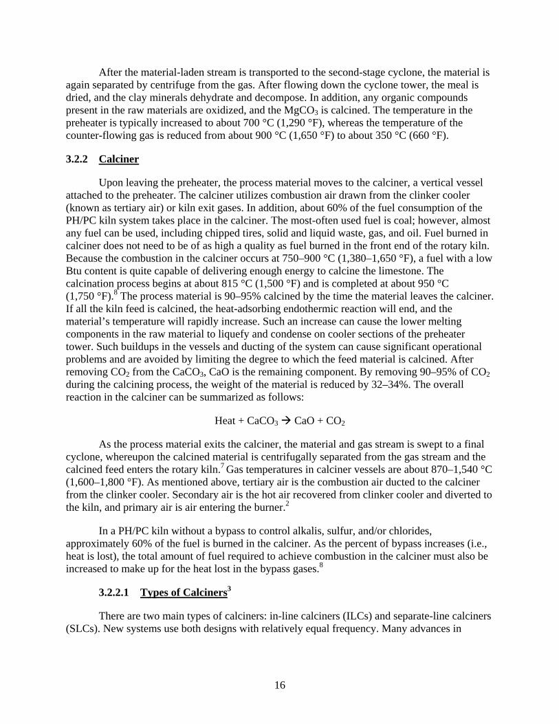
3.2.2.1.1 In-Line Calciners (ILCs)
An ILC is a calciner in which the tertiary air and kiln exhaust gas pass through the firing region of the calciner. This type of calciner is commonly used for normal fuels, such as coal, oil, gas, and wastes, with relatively high volatile bituminous coal serving as the dominant fuel. An ILC uses the hot recovered air from the cooler for fuel combustion. Since kiln combustion gases (O2 content of approximately 2%) are mixed with the air from the cooler, the oxygen content of the ILC is much less than 21%, and the temperature is normally below 900 °C (1,650 °F). The low-oxygen content and temperature makes the ILC more compatible with fuels that have relatively high volatile content. Fuels with low volatile content, such as petroleum coke, are difficult to burn in the ILC system.
Figure 3-5 shows an ILC unit with an excess air, single-string cyclone preheater kiln with a small calciner built into kiln riser duct. Combustion air for the calciner is drawn through the kiln.2
3.2.2.1.2 Separate-Line Calciners (SLCs)3
In SLCs, the kiln exhaust gas bypasses the firing region of the calciner. An SLC uses air containing 21% oxygen recovered from the cooler for combustion, and this air is not mixed with kiln combustion gases. SLCs usually have longer gas-retention times and higher temperatures, allowing these systems to use low-volatile fuels, such as petroleum coke and anthracite. Existing systems are easier to upgrade with SLCs because there are many configurations for this type of calciner. Some SLCs contain only a single string, and some SLCs have a two-string preheater tower, with the kiln gas passing through one string of the preheater and the tertiary air entering the calciner through a separate (second) string of the preheater.
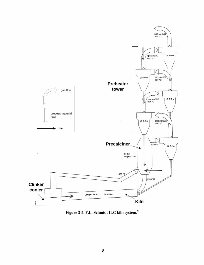
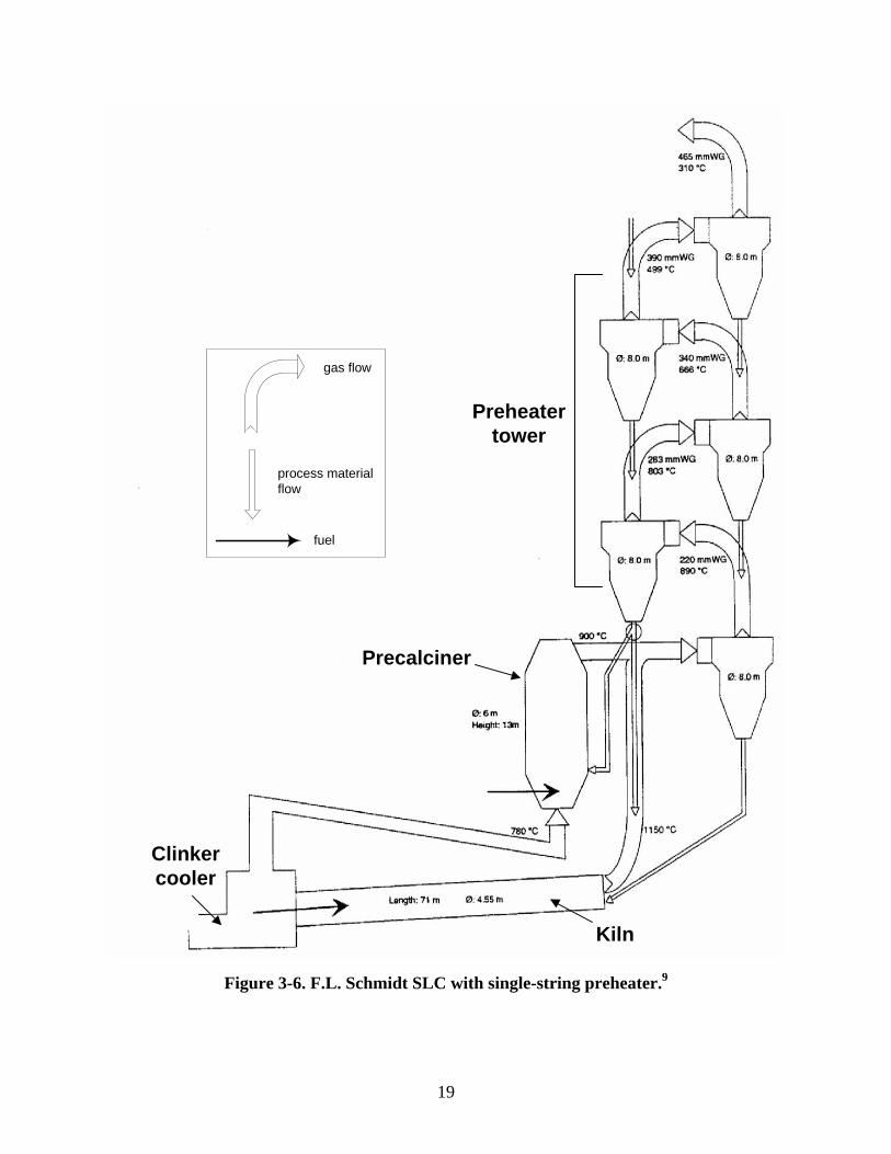
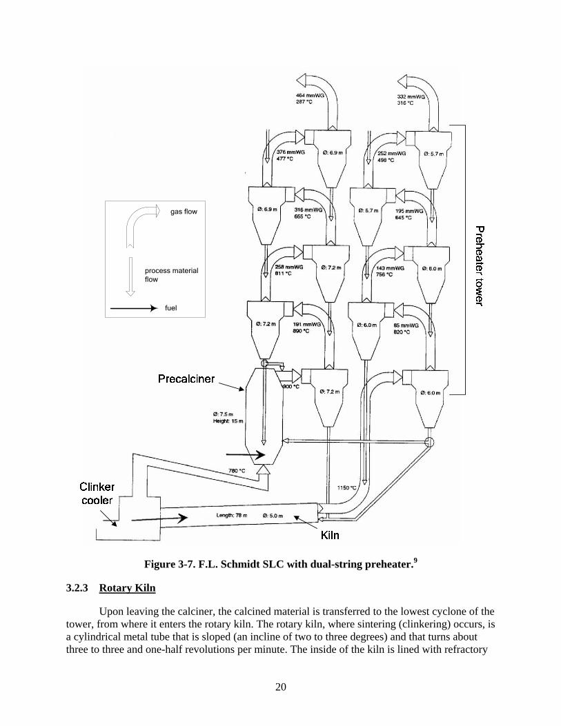
Figures 3-6 and 3-7 shows two types of SLCs. The SLC shown in Figure 3-6 is a down-draft unit, with a single-string cyclone preheater and a combustion chamber/calciner placed in parallel to the riser duct. Thus, combustion takes place using heated atmospheric air drawn from the cooler through a separate tertiary air duct, and the exhaust gas from the kiln and the combustion gases from the calciner are mixed before entering the preheater system. Figure 3-7 shows an SLC with a double-string cyclone preheater, with the combustion chamber/calciner placed in parallel to the kiln riser duct. Thus, combustion in the calciner takes place using heated atmospheric air drawn from the cooler through a separate tertiary air duct. The exhaust gas from the calciner and kiln is directed through the two independent preheater strings without being mixed.
18
Preheatertower
Precalciner
Kiln
Clinkercooler
gas flow
process material flow
fuel
Figure 3-5. F.L. Schmidt ILC kiln system.9
19
Preheatertower
Precalciner
Kiln
Clinkercooler
gas flow
process material flow
fuel
Figure 3-6. F.L. Schmidt SLC with single-string preheater.9
20
gas flow
process material flow
fuel
Figure 3-7. F.L. Schmidt SLC with dual-string preheater.9
3.2.3 Rotary Kiln
Upon leaving the calciner, the calcined material is transferred to the lowest cyclone of the tower, from where it enters the rotary kiln. The rotary kiln, where sintering (clinkering) occurs, is a cylindrical metal tube that is sloped (an incline of two to three degrees) and that turns about three to three and one-half revolutions per minute. The inside of the kiln is lined with refractory

21
brick to protect the metal from the kiln’s extreme temperature. The front (hot) end of the kiln (discharge end) contains a specially designed burner pipe, where fuel is fired to produce a high-temperature flame. The end of the kiln opposite the hot or discharge end is referred to as the feed end or rear of the kiln.
The process material enters the kiln at the feed end at a temperature of about 900 °C (1,650 °F). The gas temperature at this entry is about 1,000–1,100 °C (1,800–2,000 °F). The kiln’s slight inclination and revolution causes the solid material to progress slowly through the kiln. As the feed progresses, the material and gas temperatures slowly increase. Two essential reactions occur in the rotary kiln of a PH/PC kiln system: 1) the remaining CO2 is removed from the feed, and 2) the chemical reactions between the oxides of calcium, silicon, aluminum, and iron occur, producing a final product known as clinker. Cement clinker is a gray lava-like material that is produced in quantities about the size of a golf ball.
Many of the reactions in the rotary kiln are solid-phase or sintering reactions that occur at elevated material temperatures in close proximity to the kiln flame. This area is commonly known as the combustion zone of the kiln. The clinker minerals produced in the kiln are tetracalcium aluminoferrite ((CaO)4 Al2O3Fe2O3), tricalcium aluminate ((CaO)3 Al2O3), dicalciumsilicate ((CaO)2SiO2), and tricalcium silicate ((CaO)3 SiO2). The final reaction in the rotary kiln is the conversion of dicalcium silicate to tricalcium silicate, which only takes place above a minimum temperature in the range of 1,400–1,500 °C (2,550–2,750 °F). The reactions that occur in the rotary kiln can be represented as follows:
4 CaO + Al2O3 + Fe2O3 (CaO)4 Al2O3 Fe2O3
3 CaO + Al2O3- (CaO)3 Al2O3
2 CaO + SiO2 (CaO)2 SiO2
(CaO)2 SiO2 + CaO (CaO)3 SiO2
Clinker is produced by the chemical reaction of the dehydrated and decarbonated raw materials that occurs in the combustion zone of the rotary kiln at about 1,510 °C (2,750 °F). In the clinkering process, calcium oxide reacts at high material temperatures (1,400–1,500 °C [2,550–2,730 °F]) with silica, alumina, and ferrous oxide to form the silicates, aluminates, and ferrites of calcium that comprise the clinker. To achieve these material temperatures, gas phase temperatures will be substantially higher than 1,760 °C (3,200 °F). Oxidizing conditions must exist in the combustion zone to meet clinker quality demands; therefore, the kiln must be continuously monitored for oxygen and care must be taken to limit the amount of excess air in the system to maintain the maximum combustion zone temperature. About 20–25% of the material in the combustion zone is molten, and the cement clinker continues to change in character as it passes the zone of maximum temperature. The PH/PC kiln system permits the use of smaller-dimension kilns because preheating, drying, and calcining take place in the PH/PC portion of the system and clinkering is carried out in the rotary kiln. About 40–50% of the total fuel is burned in the rotary kiln; the rest is burned in the calciner. The operation of a PH/PC kiln system is also more stable than other kiln types because 90% of the CO2 in the feed is removed

22
prior to the feed entering the rotary kiln.9 The total material retention time in the rotary kiln is about 30 minutes.
After passing the combustion zone of the rotary kiln, the clinker is cooled to about 1,250 °C (2,300 °F) before it is discharged from the kiln into the clinker cooler. In the cooler, ambient air is forced through the clinker bed to reduce the clinker temperature to about 100 °C (200 °F). Some of the heated air from the cooler is recovered and used for combustion air in the kiln (called secondary air) and for other processes, such as combustion air for the calciner. The residence time in the cooler is about 15–30 minutes. The purpose of the cooler is to recover heat from the hot clinker and to cool the clinker such that it can be conveyed for storage and/or to be ground into cement.7 The clinker that exits the cooler is stored or directly ground in a ball/roller mill system to produce cement. To produce Portland cement, the clinker is then ground or milled together with 4–5% gypsum.
3.2.4 Alkali Bypass – PH/PC Kiln Systems
Some PH/PC kilns are equipped with an air bypass system at the feed end of the kiln. This system is typically called an alkali bypass and consists of ducting, an ID fan, and an air-pollution control device. Although certain bypass systems can be designed to remove 10–100% of the kiln combustion gases, a typical bypass system removes between 15–30% of the kiln combustion gases. The gases exiting the kiln through the bypass are cooled with air or a combination of air and water.
As described previously, the quenching of the kiln exit gases can cause volatile compounds to condense on the fine particulate in the gas stream. Some raw materials and fuels used in the rotary kiln have volatile inorganic components that are compounds combined from the elements, including potassium, sodium, sulfur, and chlorine. These compounds have a relatively low melting point, and upon reaching the combustion zone of the kiln, will volatilize and be carried with the kiln gas to the preheater, where they condense either on the wall of the vessels or on the raw material (i.e., kiln feed) entering the kiln. The part of the volatile compounds condensed on the feed reenters the combustion zone and is again volatized. This sets up an internal recirculation of volatile matter in the kiln gases entering the preheater. If the concentration of the volatile inorganic matter is great enough, and unless interrupted and removed from the kiln, it will eventually plug the vessels of the preheater. Even smaller build-ups in the preheater tower can restrict the amount of gas flow and greatly affect kiln operations. The bypass provides a valve to remove some of the volatile inorganic compounds from the kiln system to prevent such build-up in the preheater tower.
Another purpose of the bypass system is to remove excess alkali. Certain product quality standards have specific alkali limits. For example, to meet certain state highway department standards, the alkali content of some finished cements generally needs to be below a certain acceptable level. At high alkali levels, the alkalis in cement may react with certain aggregates to produce faulty concrete. To achieve low alkali in the finished cement requires low alkali levels in the clinker. In a PH/PC kiln, alkalis are re-condensed on the cooler feed coming from the calciner and reenter the combustion zone of the kiln, where they are volatilized. A bypass system can be used to break this cycle and reduce the alkali content in the clinker. Because a certain amount of air and dust (raw material that has been partially calcined) is being wasted to remove
23
the alkali inorganic material, a bypass on a cement kiln typically involves a fuel penalty between 16,000–20,000 Btu/t of clinker for every 1% of kiln gas that is bypassed. The amount of bypass required is determined primarily by the alkali and volatile inorganic content of the kiln feed. The amount of dust wasted typically ranges from 80–100 tons per day (t/day), depending on the size of the kiln system and the percent of gas bypassed. Not all PH/PC kiln systems require a bypass system, and the amount of kiln gas bypass varies during operations, as dictated by cement quality, production specification, and process.
3.3 REFERENCES 1. U.S. Environmental Protection Agency. Technology Transfer Network, Clean Air
Technology Center. RACT/BACT/LAER Clearinghouse. Web site: www.epa.gov/ttn/catc. Accessed March 6, 2007.
2. Florida Department of Environmental Protection. Technical Evaluation, Preliminary Determination, Draft BACT Determination, Sumter Cement Company. December 21, 2005. Available at www.dep.state.fl.us/Air/permitting/construction/american/ TEPD358.pdf.
3. Environment Canada. Foundation Report of the Cement Manufacturing Sector. Draft #1. Prepared by Minerals and Metals Brand, Pollution Prevention Directorate. June 18, 2004
4. Greer, W.L., and C.D. Lesslie. Variability of NOx Emissions from Precalciner Cement Kiln Systems. Trinity Consultants. Control #80. Undated.
5. Natural Resources of Central Florida. Report in Support of an application for a PSD Construction Permit Review. American Cement, Sumterville, FL. October 4, 2005. Available at http://www.dep.state.fl.us/air/permitting/construction/american.
6. U.S. Environmental Protection Agency. NOx Control Technologies for the Cement Industry. Prepared by EC/R Incorporated. September 19, 2000. Available at www.epa.gov/ttn/naaqs/ozone/ozonetech/cement_nox_update_09152000.pdf.
7. U.S. Environmental Protection Agency. Alternative Control Techniques Document – NOx Emissions from Cement Manufacturing. EPA-453/R-94-004. March 1994. Available at www.epa.gov/ttn/cata/dir1/cement.pdf.
8. U.S. Environmental Protection Agency. 11.6 Portland Cement Manufacturing. AP 42, Chapter 11.6. Available at http://www.epa.gov/ttn/chief/ap42/ch11/final/c11s06.pdf.
9. Portland Cement Association. Report on NOx Formation and Variability in Portland Cement Kiln Systems Potential Control Techniques and Their Feasibility and Cost Effectiveness. PCA R&D Serial No. 2227. Prepared by Penta Engineering Corporation. 1999.

24
[This page intentionally left blank.]
25
4.0 NOX EMISSIONS FROM PH/PC KILNS
The high temperatures and oxidizing atmosphere required for cement manufacturing are also favorable for NOx formation. In cement kilns, NOx emissions are formed during fuel combustion by two primary mechanisms:
1. The oxidation of molecular nitrogen present in combustion air (thermal NOx)
2. The oxidation of nitrogen compounds in fuel (fuel NOx).1
Sometimes, the raw material feed may also contain nitrogen compounds, which may lead to feed NOx similar to fuel NOx. Because of the high temperatures involved in burning or clinker formation, thermal NOx is the dominant mechanism for NOx formation in kiln systems.
4.1 THERMAL NOX
Thermal NOx results from the homogeneous reaction of oxygen and nitrogen in the gas phase at high temperatures. In the overall reaction mechanism developed by Zeldovich, the two important steps in the formation of thermal NOx are the following:
2 N2 + O2 2 NO + 2 N
N + O2 NO +O
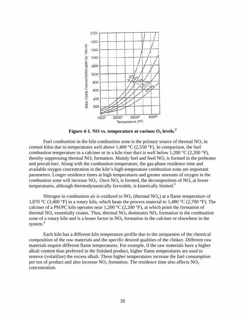
The excess air used during fuel combustion can substantially affect NO formation by determining the amount of oxygen available for NO reaction. The cement kiln combustion zones usually have about 5–10% excess air, although higher excess air levels are not uncommon. Higher excess air levels result in higher NOx. Also, as shown in Figure 4-1, small increases in temperature result in very large increases of NO concentrations at temperatures above 1,430 °C (2,600 °F).
26
Figure 4-1. NO vs. temperature at various O2 levels.2
Fuel combustion in the kiln combustion zone is the primary source of thermal NOx in cement kilns due to temperatures well above 1,400 °C (2,550 °F). In comparison, the fuel combustion temperature in a calciner or in a kiln riser duct is well below 1,200 °C (2,200 °F), thereby suppressing thermal NOx formation. Mainly fuel and feed NOx is formed in the preheater and precalciner. Along with the combustion temperature, the gas-phase residence time and available oxygen concentration in the kiln’s high-temperature combustion zone are important parameters. Longer residence times at high temperatures and greater amounts of oxygen in the combustion zone will increase NOx. Once NOx is formed, the decomposition of NOx at lower temperatures, although thermodynamically favorable, is kinetically limited.3
Nitrogen in combustion air is oxidized to NOx (thermal NOx) at a flame temperature of 1,870 °C (3,400 °F) in a rotary kiln, which heats the process material to 1,480 °C (2,700 °F). The calciner of a PH/PC kiln operates near 1,200 °C (2,200 °F), at which point the formation of thermal NOx essentially ceases. Thus, thermal NOx dominates NOx formation in the combustion zone of a rotary kiln and is a lesser factor in NOx formation in the calciner or elsewhere in the system.4
Each kiln has a different kiln temperature profile due to the uniqueness of the chemical composition of the raw materials and the specific desired qualities of the clinker. Different raw materials require different flame temperatures. For example, if the raw materials have a higher alkali content than preferred in the finished product, higher flame temperatures are used to remove (volatilize) the excess alkali. These higher temperatures increase the fuel consumption per ton of product and also increase NOx formation. The residence time also affects NOx concentration.

27
4.2 FUEL NOX 4
Fuel NOx is formed by the oxidation of nitrogen present in fuel. The oxidation reactions of nitrogen from fuel are complex and occur through many intermediate products and radicals. As the fuel burns, the nitrogen that was chemically bonded as part of the fuel molecule is freed and can combine with oxygen to form NOx.5 About 80% of the energy requirements for the PH/PC kiln systems are met by coal, whereas natural gas provides only 3%, oil provides less than 1%; and other fuels such as waste solvents provide 14%. Oil and natural gas have relatively low fuel-bound nitrogen content, whereas coal may have 1–3% nitrogen by weight. In addition, waste-derived fuels (e.g., scrap tires, used motor oils, paint thinners) are being used increasingly as fuel for PH/PC kilns and may have significant nitrogen content.
The maximum possible fuel NOx conversion can be estimated for a PH/PC kiln system. As shown in Table 3-3, the heat input requirement for this type of kiln is 3.3 mmBtu/t of clinker. Assuming a coal heating value of 12,000 Btu/lb, 275 lb of coal would be required per ton of clinker. With a nitrogen content of 1% by weight, approximately 5.9 lb of NOx would be produced per ton of clinker, assuming 100% nitrogen conversion.
Because kiln measurements indicate the total NOx formed, it is difficult to distinguish the levels of thermal NOx and fuel NOx. In general, thermal NOx is thought to be the dominant mechanism in cement kilns. Gas burners produce more intense and hot flames compared to coal burners; thus, gas-fired kilns may be expected to produce greater thermal NOx than coal-fired kilns. A study has indicated that gas-fired, dry-process kilns typically produce almost three times more NOx than coal-fired, dry-process kilns.
Fuel NOx predominates NOx generation in the calciner and at lower-temperature combustion sites. Fuel NOx also occurs in the combustion zone of a rotary kiln.7 Approximately 60% of fuel nitrogen is converted to NOx and is dependent upon available oxygen in the flame and temperature profile of the flame.8
When fired in the main kiln burner, natural gas has been shown to generate approximately twice the amount of NOx per ton of clinker as coal or oil. This is not readily apparent because the adiabatic flame temperatures of coal and oil are higher than for natural gas. In addition, coal and oil have more fuel nitrogen than natural gas and are generally fired with a higher volume of combustion air, which increases the oxygen available and the potential for NOx formation. There are other factors associated with coal and oil burning that more than offset the factors mentioned above, including flame shape, the luminescence of the flame and higher levels of CO, and various radicals that counter NOx formation.
Calciner kilns burn 50–60% of the total fuel at a lower temperature (1,200 °C [3,630 °F]) in the kiln. This leads to negligible thermal NO formation in the calciner; thus, thermal NOx in PH/PC kiln systems is much lower than other kiln types.9
About 15–30% of fuel NOx is converted in the calciner in the absence of tertiary air, and 30–75% is converted when tertiary air is supplied. In a low NOx calciner, NOx levels in the gases exiting the preheater are 35–50% lower than kilns without calciners.6

28
4.3 FEED NOX 10
Feed NOx is generated when nitrogen in the raw materials that are fed to the kiln are oxidized. The raw materials used in cement production may contain a significant amount of nitrogen. Limestone is the major raw material, with the remainder of the raw mix being clays, shales, sandstones, sands, and iron ore. The nitrogen content for various kiln feeds ranges from 20 to 1,000 parts per million (ppm). 100 ppm of nitrogen in the kiln feed is equivalent to about 1 lb of NOx per ton of clinker if all the nitrogen in the feed is converted.
The conversion of feed nitrogen to NOx occurs mainly in the 300–800 °C (570–1,470 °F) range and depends on the feed heating rate. The rapid heating of raw materials in PH/PC kiln system is thought to result in less feed NOx generation than the slower heating of kiln feed found in other types of kiln. Rapid heating rates (~ 100 °C flash heating) of the kiln feed mixtures were found to give much lower conversion efficiencies, whereas a slow heating rate of kiln feed mixtures (~60 °C/min) gave a fairly high conversion (about 50% of bound nitrogen to NO). The explanation for this is the assumption that organic nitrogen must vaporize from the sample prior to oxidation if high conversion efficiencies to NOx are to be achieved. If heating rates are rapid, “cracking” of these volatile compounds may occur in situ, which may result in conversion of the bound nitrogen directly to N2 before it comes into contact with gaseous oxygen, thus reducing the fraction converted to NOx; therefore, feed NOx is not likely to be a significant contributor to NOx emissions from a PH/PC kiln system.
4.4 PROMPT NOX
Prompt NOx is formed when free radicals from the fuel react with available N2 in the combustion air. Free radicals are generated by the use of excess fuel-forming HC radicals, which rapidly react with N2 to form hydrogen cyanide (HCN) and nitrogen. Through a cascade of reactions, NH3 can also form. As combustion continues, the HCN and NH3 result in the generation of NOx. These reactions are summarized as follows:
CH + N2 HCN + N
C + N2 CN + N
N + OH NO + H
The rate of formation of prompt NOx is very rapid, and reactions are not strongly temperature dependent and occur in a fuel-rich environment. The contribution of prompt NOx to overall NOx formation in a cement kiln is small because prompt NOx tends to dominate when the total NOx concentration in the system is low, but in cement kilns, the NOx concentrations are relatively high.
4.5 REFERENCES 1. Environment Canada. Foundation Report of the Cement Manufacturing Sector. Draft #1.
Prepared by Minerals and Metals Brand, Pollution Prevention Directorate. June 18, 2004.

29
2. Zeldovich, J. 1946. The Oxidation of Nitrogen in Combustion and Explosions. Acta Physiochem. 1946.
3. U.S. Environmental Protection Agency. NOx Control Technologies for the Cement Industry. Prepared by EC/R Incorporated. September 19, 2000. Available at www.epa.gov/ttn/naaqs/ozone/ozonetech/cement_nox_update_09152000.pdf.
4. Greer, W.L., and C.D. Lesslie. Variability of NOx Emissions from Precalciner Cement Kiln Systems. Trinity Consultants. Control #80. Undated.
5. Webster, T., and S. Drennen. Low NOx Combustion of Biomass Fuels. Available at http://www.coen.com/i_html/white_lownoxbiom.html. Accessed August 2, 2006.
6. U.S. Environmental Protection Agency. Technology Transfer Network, Clean Air Technology Center. RACT/BACT/LAER Clearinghouse. Web site: www.epa.gov/ttn/catc. Accessed March 6, 2007.
7. Florida Department of Environmental Resources. BACT Determination – Suwannee American Cement, Branford Florida. Air NSR/PSD Construction Permits. Available at http://www.dep.state.fl.us/Air/permitting/construction/suwannee.htm. Accessed March 6, 2007.
8. Natural Resources of Central Florida. Report in Support of an application for a PSD Construction Permit Review. American Cement, Sumterville, FL. October 4, 2005. Available at http://www.dep.state.fl.us.air/permitting/construction/sumter.
9. Tokheim, L.-A. The Impact of Staged Combustion on the Operation of a Precalciner Cement Kiln. Telemark College, Porsgrumm, Norway. Available at www.cement.org/dnld/Staged percent20 Combustion percent20Dissertation.pdf.
10. Greer, W.L., and C.D. Lesslie. Variability of NOx Emissions from Precalciner Cement Kiln Systems. Trinity Consultants. Control #80. Undated.

30
[This page intentionally left blank.]

31
5.0 FACTORS AFFECTING NOX EMISSIONS
As discussed in Section 3, high temperatures are necessary for the required clinkering reactions to take place in the cement kiln. If a kiln’s temperature drops too low, the clinker formation reactions will stop, and because these reactions are exothermic, the temperature will drop even further. The temperature must be raised by increasing the energy (fuel) input to the kiln. Once the clinkering formation reactions start again, the temperature will increase very rapidly, again requiring an adjustment of fuel input. These process variations, which result in temperature variations, are normal in cement kiln operations and can produce significant variations in NOx emissions.
Changes in the fuel used for kilns can also change a kiln’s temperature and the shape of the kiln flame, which can precipitate temperature changes in the kiln combustion zone. Flame temperatures are greater for gas burners than for coal burners. In addition to temperature variations that can initiate thermal NOx formation, fuels with higher nitrogen content will have more nitrogen available for fuel NOx formation.
As with fuel, changes in the feed rate, chemical composition, or moisture content of raw materials can also change a kiln’s operating parameters. Even raw materials from the same quarry can vary in chemical composition from day to day. Materials with higher nitrogen content can lead to more feed NOx formation. Raw materials that contain unacceptably high alkali content must be heated longer and at higher temperatures to volatilize and remove the alkali compounds. If alkali compounds are volatilized from the raw material, they appear in the kiln exhaust gases. As discussed in Section 3, a bypass system can be used to control these alkali emissions. In a bypass system, a portion of the kiln exhaust gases is rapidly cooled or quenched in order for the alkali materials to condense and be collected directly by a particulate control device. This lowers the overall system heat efficiency, requiring more energy to be added to the system, again contributing to additional NOx formation.
The energy efficiency of a kiln system can also affect NOx formation. As clinker exits the kiln, it is cooled with ambient air. The heat from the clinker is transferred to the air, and this heated air is recycled to preheat a significant portion of the secondary combustion air and to reach the high flame zone temperatures necessary for Portland cement production. In addition, some heat-recovery methods require less energy input into the kiln. This reduced heat (and fuel) input into the kiln system reduces the formation of NOx.
Excess oxygen is required to produce quality clinker, but higher oxygen levels result in higher NOx emissions. The oxygen concentration in the combustion zone depends on the percentage of excess air used and the ratios of the primary and secondary combustion. Additional combustion for PH/PC kilns takes place in the calciner. As noted in Section 3, secondary combustion air may be used for combustion in the calciner. The secondary combustion air usually comes from the clinker cooler; however, some calciners will use kiln gases as the source of combustion air rather than secondary air from the cooler. The source of the secondary and primary air determines the air’s oxygen content. Less primary air means less oxygen and may produce an initial high-temperature, fuel-rich combustion zone, followed by a low-temperature fuel-lean combustion zone. Such a combination is likely to reduce the formation of NOx.

32
The proportions of primary and secondary combustion air are affected by the type of firing system used in the kiln. Direct-fired systems use combustion air to transport fuel into the kiln. Therefore, a large proportion of the combustion air is introduced with the fuel as primary air. This produces two conflicting effects for NOx emissions: higher oxygen concentrations and lower gas temperatures. In contrast, indirect-fired systems use only a small portion of combustion air to convey fuel; thus, these systems use less cold primary air. Therefore, indirect-fired systems use more secondary air with additional heat value as the combustion air. In general, direct-fired systems may be expected to produce greater NOx emissions compared to indirect-fired systems. The majority of kilns in the United States are direct-fired systems.

33
6.0 PROCESS CONTROLS THAT REDUCE NOX EMISSIONS 1, 2
The primary goals of process controls are to stabilize process parameters and to stabilize kiln conditions. The process controls used to stabilize kiln operations also improve energy efficiency by reducing heat consumption, improve clinker quality, and increase the life of the cement plant. Another beneficial effect of process controls is the reduction of NOx emissions because of improved fuel efficiency.
When determining uncontrolled NOx emissions, the following standard operating practice (SOP) components should be considered. These SOPs are incorporated by all new PH/PC kiln systems.
Combustion zone control of temperature and excess air through continuous monitoring of temperature and excess air
Feed mix composition Kiln fuel type Increased thermal efficiency Staged combustion in kiln Efficient cooler control Expert control systems Low NOx burners in the kiln.
These components are discussed in detail in previous EPA documents.1, 2 A summary of these measures is contained in the following subsections.
6.1 COMBUSTION ZONE CONTROL OF TEMPERATURE AND EXCESS AIR1, 2
Continuous monitoring of CO and O2 emissions in the exhaust gases of cement kilns indicates the amount of excess air. At any given excess air level, NOx emissions increase as the temperature of the combustion zone increases. Keeping the combustion zone temperature at a minimum acceptable value minimizes the process energy requirements and NOx emissions.
With continuous CO, O2, and NOx monitors and feedback control, excess air can be accurately controlled to maintain a level that provides optimum combustion and lower NOx emissions. Reducing excess air levels also results in increased productivity per unit of energy; thus, resulting in the indirect reduction of NOx emissions per amount of clinker produced.
6.2 FEED MIX COMPOSITION
Heat requirements for producing clinker are dependent on the composition of the raw material. Experiments have demonstrated that by improving the burnability of the kiln feed, the heat requirements for producing clinker can be reduced by 15%, thereby requiring less fuel (i.e., less heat input per ton of clinker) and producing less NOx per unit of product. This approach of changing feed composition may be highly site specific and may not be applicable to all locations.
The level of heat input required to complete the clinkering reactions depends on the chemical and moisture composition of the raw feed materials. Raw materials can vary widely
34
between cement plants, as well as within the same plant. One example of this practice is to use raw materials with as low an alkali content as possible because high alkali materials require more heat and a longer residence time to volatilize.
If the raw materials are consistently proportioned and blended before entering the kiln, the temperatures and excess air requirements should remain constant. Keeping temperatures as low and as constant as possible reduces the overall energy requirements, increases fuel efficiency, and reduces NOx formation.
6.3 KILN FUEL
The type of kiln fuel used directly affects the formation of NOx. Using coal instead of natural gas results in lower uncontrolled NOx emissions because the flame temperature for coal is significantly lower than natural gas. In one study of dry process kilns, the average NOx emissions decreased from 20.4 to 6.2 lb/t of clinker when the fuel was changed from natural gas to coal. Approximately 80% of primary fuel burned in cement kilns is coal.
For PH/PC kiln systems, emissions of NOx range from 1.7–3.0 kg/t of clinker (3.7–6.6 lb/t) for kiln systems fueled by natural gas and 1.35–1.95 kg/t of clinker (3.0–4.3 lb/t) for kiln systems fueled by coal.3
6.4 INCREASING THERMAL EFFICIENCY
As shown in Table 3-3, the PH/PC kiln system is the most energy efficient of the cement kilns. The energy efficiency benefit varies from 15–30% depending on the type of conventional kiln system used for comparison. The thermal efficiency of the PH/PC kiln system may be increased by improving gas/solids heat transfer (e.g., by using an efficient chain system, increasing the heat recovery from the clinker cooler by increasing the proportion of secondary air, and minimizing infiltration of ambient air leakage into the kiln).
6.5 STAGED COMBUSTION IN KILN
The staging of fuel combustion occurs in two distinct zones. In the first zone, initial combustion is conducted in a primary fuel-rich zone. This zone provides the high temperatures needed for completion of the clinkering reactions. Due to the fuel-rich conditions and the lack of available oxygen, the formation of thermal and fuel NOx is minimized. In the second zone, fuel combustion is completed, with additional (secondary) combustion air added to complete the combustion process. The gas temperature in the second zone is much lower than the first zone because the gas is mixed with cooler secondary air, thereby minimizing NOx formation despite the excess available oxygen in this zone. Indirect-fired kilns are required for effective staging of combustion air.
6.6 EFFICIENT COOLER CONTROL 4
Improved heat recovery from the clinker cooler will result in better fuel efficiency for the PH/PC system. Heat recovered from the clinker cooler does not need to be generated from fuel burning. Other ways to improve the reuse of heat from the clinker cooler include optimizing the cooler’s layout and the design of the ID fan.
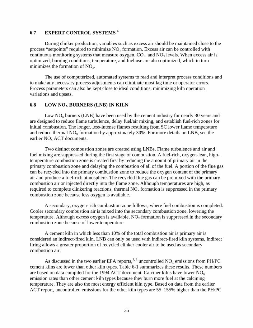
35
6.7 EXPERT CONTROL SYSTEMS 4
During clinker production, variables such as excess air should be maintained close to the process “setpoints” required to minimize NOx formation. Excess air can be controlled with continuous monitoring systems that measure oxygen, CO2, and NOx levels. When excess air is optimized, burning conditions, temperature, and fuel use are also optimized, which in turn minimizes the formation of NOx.
The use of computerized, automated systems to read and interpret process conditions and to make any necessary process adjustments can eliminate most lag time or operator errors. Process parameters can also be kept close to ideal conditions, minimizing kiln operation variations and upsets.
6.8 LOW NOX BURNERS (LNB) IN KILN
Low NOx burners (LNB) have been used by the cement industry for nearly 30 years and are designed to reduce flame turbulence, delay fuel/air mixing, and establish fuel-rich zones for initial combustion. The longer, less-intense flames resulting from SC lower flame temperature and reduce thermal NOx formation by approximately 30%. For more details on LNB, see the earlier NOx ACT documents.
Two distinct combustion zones are created using LNBs. Flame turbulence and air and fuel mixing are suppressed during the first stage of combustion. A fuel-rich, oxygen-lean, high-temperature combustion zone is created first by reducing the amount of primary air in the primary combustion zone and delaying the combustion of all of the fuel. A portion of the flue gas can be recycled into the primary combustion zone to reduce the oxygen content of the primary air and produce a fuel-rich atmosphere. The recycled flue gas can be premixed with the primary combustion air or injected directly into the flame zone. Although temperatures are high, as required to complete clinkering reactions, thermal NOx formation is suppressed in the primary combustion zone because less oxygen is available.
A secondary, oxygen-rich combustion zone follows, where fuel combustion is completed. Cooler secondary combustion air is mixed into the secondary combustion zone, lowering the temperature. Although excess oxygen is available, NOx formation is suppressed in the secondary combustion zone because of lower temperature.
A cement kiln in which less than 10% of the total combustion air is primary air is considered an indirect-fired kiln. LNB can only be used with indirect-fired kiln systems. Indirect firing allows a greater proportion of recycled clinker cooler air to be used as secondary combustion air.
As discussed in the two earlier EPA reports,1, 2 uncontrolled NOx emissions from PH/PC cement kilns are lower than other kiln types. Table 6-1 summarizes these results. These numbers are based on data compiled for the 1994 ACT document. Calciner kilns have lower NOx emission rates than other cement kiln types because they burn more fuel at the calcining temperature. They are also the most energy efficient kiln type. Based on data from the earlier ACT report, uncontrolled emissions for the other kiln types are 55–155% higher than the PH/PC
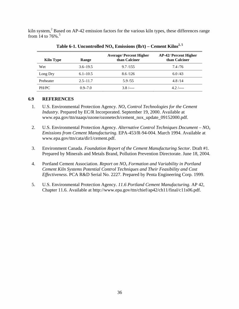
36
kiln system,2 Based on AP-42 emission factors for the various kiln types, these differences range from 14 to 76%.5
Table 6-1. Uncontrolled NOx Emissions (lb/t) – Cement Kilns2, 5
Kiln Type Range Average/ Percent Higher
than Calciner AP-42/ Percent Higher
than Calciner
Wet 3.6–19.5 9.7 /155 7.4 /76
Long Dry 6.1–10.5 8.6 /126 6.0 /43
Preheater 2.5–11.7 5.9 /55 4.8 /14
PH/PC 0.9–7.0 3.8 /---- 4.2 /----
6.9 REFERENCES 1. U.S. Environmental Protection Agency. NOx Control Technologies for the Cement
Industry. Prepared by EC/R Incorporated. September 19, 2000. Available at www.epa.gov/ttn/naaqs/ozone/ozonetech/cement_nox_update_09152000.pdf.
2. U.S. Environmental Protection Agency. Alternative Control Techniques Document – NOx Emissions from Cement Manufacturing. EPA-453/R-94-004. March 1994. Available at www.epa.gov/ttn/cata/dir1/cement.pdf.
3. Environment Canada. Foundation Report of the Cement Manufacturing Sector. Draft #1. Prepared by Minerals and Metals Brand, Pollution Prevention Directorate. June 18, 2004.
4. Portland Cement Association. Report on NOx Formation and Variability in Portland Cement Kiln Systems Potential Control Techniques and Their Feasibility and Cost Effectiveness. PCA R&D Serial No. 2227. Prepared by Penta Engineering Corp. 1999.
5. U.S. Environmental Protection Agency. 11.6 Portland Cement Manufacturing. AP 42, Chapter 11.6. Available at http://www.epa.gov/ttn/chief/ap42/ch11/final/c11s06.pdf.

37
7.0 STAGED COMBUSTION
There are many ways a PH/PC kiln system could be considered to be using staged combustion (SC). First, the processes of the PH/PC kiln system itself, which include the drying, calcining, and sintering of the raw materials, can be considered SC. Also, the kiln with a multi-channel main kiln burner with indirect firing incorporates SC. All calciners have some degree of SC. The use of low NOx calciners, which inject fuel near the kiln inlet, is a form of SC. This section will discuss SC in the calciner (SCC).
7.1 STAGED COMBUSTIN IN THE CALCINER (SCC) MECHANISM
The various zones of the PH/PC kiln system are shown in Figure 7-1. In the PH/PC kiln system, NOx formation occurs in the rotary kiln under oxidizing conditions. Fuel is then added to the kiln exhaust gas, in the kiln inlet, or in the kiln riser duct so that a reducing zone (a zone where less air is available than would be required for complete combustion) is created. This promotes the reduction of NOx to molecular oxygen. Finally, air is added in the upper part of the calciner, which completes fuel combustion.1 This part of the calciner is known as the burnout zone. When the air-to-fuel ratio equals 1, the exact amount of air is present for fuel combustion. At an air-to-fuel ratio greater than 1, more air is present than is necessary to complete fuel combustion, whereas at an air-to-fuel ratio less than 1, the amount of air present is not sufficient for fuel combustion.
SCC works by staging the introduction of fuel, combustion air, and raw meal in a manner to minimize NOx formation and reduce NOx to nitrogen. NOx formed in the kiln’s combustion zone is chemically reduced by maintaining a reducing atmosphere at the kiln feed end by firing fuel in this region. The reducing atmosphere is maintained in the calciner region by controlling combustion air such that the calcining fuel is first burned under reducing conditions to reduce NOx, and then burned under oxidizing conditions to complete the combustion reaction. Controlling the introduction of raw meal allows for control of the calciner temperature. Through these mechanisms, both fuel NOx and thermal NOx are controlled. The combustion chamber allows for improved control over the introduction of tertiary air in the calciner region, which helps to promote the proper reducing environment for NOx control.2
All new PH/PC kiln systems are designed with multistage combustion (MSC) calciners. MSC is actually the version of SC as applied by Polysius. There are several SCC variations based on fuel staging or air staging (or both) (see Sections 7.2.1 through 7.2.3 for descriptions). According to a Florida Department of Environmental Protection (DEP) expert, the best version of SCC would be an SCC with High Temperature Reducing Atmosphere (HTRA). HTRA is achieved when some or all calciner fuel is burned under aggressive reducing (substoichiometric air) and at temperatures significantly higher than calcination temperature. Under such conditions, the gas phase reactions that destroy NOx proceed very rapidly and are catalyzed by raw meal. Some additional reduction takes place at lower (calcination) temperature as you get char combustion. The lower NOx emission level achieved by SCC with HTRA is 2.0 lb/t of clinker.
A key component of SCC is the kiln inlet burner that creates a high-temperature reducing atmosphere. Some projects are considered to be SCC even when they achieve a mild reducing

38
atmosphere. Some SCC have a high NOx limit and are operated under an oxidizing atmosphere which is easier for operations.3
Rotary kilnRotary kiln
Reduction zoneAir-to-fuel ratio < 1
Reduction zoneAir-to-fuel ratio < 1
Burnout zoneAir-to-fuel ratio > 1
Burnout zoneAir-to-fuel ratio > 1
Cooler
Calciner
Tertiary air duct(from clinker cooler)
Preheater
Figure 7-1. Principle of NOx reduction by SCC.4
SCC involves four combustion stages. The first stage is the rotary kiln, where clinker burning can be optimized. The second stage is the kiln feed inlet, which provides reducing conditions for NOx generated during the sintering process. In the third stage, fuel is introduced into the calciner to calcine the raw meal. This calcining fuel is introduced with tertiary air to create a reducing atmosphere. The last stage is when the remaining tertiary air is introduced as “top-up air” to complete the residual combustion process.5 SCC systems are complex and require integrated monitoring and control systems to closely monitor temperature, fuel, feed, and combustion air addition rates. If raw materials are not completely oxidized in the calciner and preheater, CO emissions may increase.
The factors affecting NOx levels for SCC are summarized in Table 7-1.
Table 7-1. Parameters Affecting NOx and Staged Combustion Responses 6
Kinetic Parameters Influencing NOx
Process Parameter Influencing NOx Measures for NOX Reduction
Oxygen concentration Air-to-fuel ratio Air staging NO concentration NO at kiln inlet Decrease O2 in rotary kiln NH3, HCN, HC, CO concentrations Residence time Calciner design Same as above Mixing of gas streams Adjustment of burners, distribution
of meal, and tertiary air Same as above Fuel properties Increase fineness, change fuel Temperature Temperature Meal staging
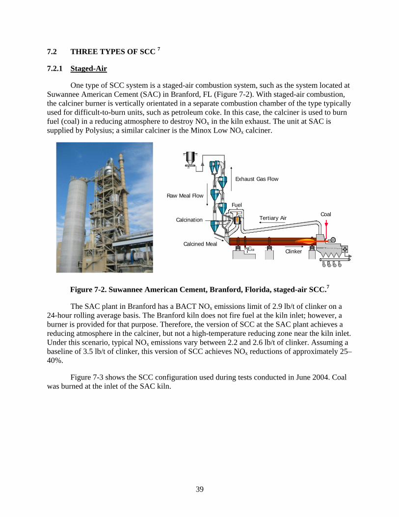
39
7.2 THREE TYPES OF SCC 7
7.2.1 Staged-Air
One type of SCC system is a staged-air combustion system, such as the system located at Suwannee American Cement (SAC) in Branford, FL (Figure 7-2). With staged-air combustion, the calciner burner is vertically orientated in a separate combustion chamber of the type typically used for difficult-to-burn units, such as petroleum coke. In this case, the calciner is used to burn fuel (coal) in a reducing atmosphere to destroy NOx in the kiln exhaust. The unit at SAC is supplied by Polysius; a similar calciner is the Minox Low NOx calciner.
Exhaust Gas Flow
Raw Meal Flow
Tertiary Air
Clinker
CoalCalcination
Fuel
Calcined Meal
Figure 7-2. Suwannee American Cement, Branford, Florida, staged-air SCC.7
The SAC plant in Branford has a BACT NOx emissions limit of 2.9 lb/t of clinker on a 24-hour rolling average basis. The Branford kiln does not fire fuel at the kiln inlet; however, a burner is provided for that purpose. Therefore, the version of SCC at the SAC plant achieves a reducing atmosphere in the calciner, but not a high-temperature reducing zone near the kiln inlet. Under this scenario, typical NOx emissions vary between 2.2 and 2.6 lb/t of clinker. Assuming a baseline of 3.5 lb/t of clinker, this version of SCC achieves NOx reductions of approximately 25–40%.
Figure 7-3 shows the SCC configuration used during tests conducted in June 2004. Coal was burned at the inlet of the SAC kiln.
40
Figure 7-3. Suwannee American, Branford, Florida, Polysius MSC – SCC
with kiln inlet burner.7
7.2.2 Air and Fuel Staging
A second type of SCC system (Figure 7-4) is an air and fuel staging system, such as the system used at the Florida Rock Industries (FRI) plant in Newberry, FL. This is a Polysius MSC system, horizontally mounted ILC. The calcination burner is mounted horizontally rather than in a separate combustion chamber. Provisions are included for a small burner in the kiln inlet housing. FRI burns tires at the kiln inlet.
Figure 7-4. Florida Rock Industries, Newberry, Florida, air and fuel staging – SCC.7
This FRI kiln has a BACT NOx emissions limit of 2.45 lb/t of clinker on a 30-day rolling average basis. Data from the first half of 2004 are available and show that typical emissions from the FRI kiln are between 1.5 and 2.5 lb/t of clinker, when tires are burned near the kiln inlet. The 30-day average emissions range from 1.8–2.4 lb/t of clinker, and daily averages range from 1.0–3.7 lb/t of clinker. According to FRI, higher values near 3 lb/t of clinker are observed on days
StagedAir
Fuel
KilnCalcined Meal
Raw Meal
Air
StagedAir
FuelCalcined Meal
Kiln
ReburnFuel

41
when tires were not available, which verifies that fuel burning at the kiln inlet and inducing high temperature in the reducing zone can lower NOx emissions.
7.2.3 Sequenced Fuel and Air
A third type of SCC system (Figure 7-5) is a sequenced fuel and air introduction system, such as the system used at the Titan America plant in Medley, FL. This is a low NOx ILC. All fuel is fired in a reducing atmosphere near the kiln inlet, and tertiary air is supplied in the lower part of the calciner. Raw meal is split and introduced at different sections of the calciner. Effective SCC designs typically incorporate meal staging for numerous reasons. One key reason is to take advantage of the catalytically enhanced dissociation in the preheater of NO formed in the kiln. Another important reason is as a temperature-control strategy.
This type of calciner does not stage fuel or air, but instead injects all calciner fuel at the bottom of the calciner, before the kiln inlet. All tertiary air is introduced at a single point just above the fuel. A high-temperature reducing zone is created in the kiln riser duct, and the calciner is partially built into the kiln riser. The tertiary air quickly lowers the temperature after the reducing zone, and SO2 volatilization is limited. This reduces the potential for coating of surfaces with sulfur compounds; thus, coating and plugging are not a problem.
Figure 7-5. Titan America, Medley, Florida, sequenced fuel and air – SCC.7
Compliance tests at the new 250 t/hr Titan America kiln showed NOx and CO emissions at 2.0 and 0.5 lb/t of clinker, respectively. This calciner is not a true SCC system, i.e., it does not stage fuel (e.g., use two burners in the calciner) or stage air (e.g., use two tertiary air inputs to the calciner). Instead, it depends on the introduction of all calciner fuel into a reducing atmosphere near the bottom of the calciner (not actually at the kiln inlet), followed by the introduction of all tertiary air at a single level just above the fuel introduction point.
Averaged over the long term, a well-operated MSC plant under reducing conditions in the calciner can achieve NOx emissions at 2.3–2.5 lb/t of clinker. Staging can involve either the staging of fuel combustion, combustion air, or both. The basic MSC system operating under oxidizing conditions throughout will result in NOx emissions of about 3.5–4.0 lb/t of clinker.7
AirFuel
Raw Meal
CalcinedMealKiln
42
The MSC system can be operated with combustion at various points given the system’s fuel-rich conditions. If a kiln inlet burner is used or if tire-derived fuel is fired as supplemental fuel at kiln inlet, combustion can occur with sub-stoichiometric combustion air. This creates a reducing atmosphere around 1,000–1,100 °C (1,830–2,010 °F). Under these high-temperature reducing conditions, a good portion of NOx generated in the kiln is converted to N2, thereby reducing NOx emissions. This concept is similar to reburning.
7.3 SUMMARY OF SCC NOX PERFORMANCE
Table 7-2 is from a Canadian agency report5 and summarizes information obtained on several U.S. cement plants and one Canadian plant. Most of the data represents permit data; however, emission test data is provided for a few plants. These emissions data reflect the results of using multiple NOx controls, including MSC. There are 12 kilns with MSC, process controls and LNBs, with emissions ranging from 0.6–1.65 kg/mt (1.2–3.2 lb/t of clinker). The average of the emissions of the 11 U.S. kilns that have only process controls, LNBs, and MSC is 1.35 kg/mt (2.7 lb/t of clinker). Several other plants use these and other controls.

43
Table 7-2. NOx Emissions Performance of Selected Cement Plants 5
A European study8 indicates that most current European standards (200–500 mg/Nm3 [1.0–2.4 lb/t of clinker]) can be met by MSC systems manufactured by Polysius. Another European reference states that there is a 10–50% reduction attributable to SCC that achieves emission levels < 500–1000 mg/m3 (< 2.4–4.8 lb/t of clinker).4

44
Table 7-3 summarizes the level of performance in U.S. kilns expected from SCC with other NOx controls (primarily combustion and process controls) in place (e.g., LNB in kiln and process controls). As shown in this table, the NOx level varies considerably from 1.4–3.3 lb/t of clinker. The average of these NOx levels (excluding those kilns that burn tires) is 2.5 lb/t of clinker.
Table 7-3. Summary of NOx Performance of SCC in U.S. Kilns
Source/Location
NOx Uncontrolled
(lb/t) NOx Controlled
(lb/t) Efficiency
11 US kilns(from Table 7-2) NA 2.2–3.3 (avg. 2.7)
NA
Florida Rock 3.5 3.0 -w/o tires 1.5–2.5 (midpoint 2.0) -w/ tires
17% -w/otires 43% -w/ tires
Suwannee American NA 2.2–2.6 (range) 2.4 (midpoint)
NA
Titan American NA 2.0 NA
Lone Star 2.8 1.8 35%
Cemex Santa Cruz 9 NA 2.5 (0% coal to reducing zone 1.7 (50% coal to reducing zone)
1.4 (100% coal to reducing zone) 1.8 (midpoint)
NA
7.4 LIMITATIONS OF MULTISTAGE COMBUSTION (MSC) – HIGH SULFUR
In kiln systems that have a process mix with a high sulfur to alkali molar ratio, the volatility of sulfur increases due to the strong reducing conditions of MSC and relatively low oxygen content in the system. Operationally, this increase causes severe preheater plugging to occur due to the significant sulfur deposition associated with MSC operation. The required conditions needed for optimum MSC operation (low excess oxygen) conflict with the goal of preventing sulfur deposition and minimizing operational problems. Thus, a high sulfur/alkali molar feed ratio prevents the achievement of maximum NOx reduction using MSC.11 [last]
7.5 REFERENCES 1. Tokheim, L.-A. The Impact of Staged Combustion on the Operation of a Precalciner
Cement Kiln. Telemark College, Porsgrumm, Norway. Available at www.cement.org/dnld/Staged percent20 Combustion percent20Dissertation.pdf.
2. Florida Department of Environmental Resources. BACT Determination – Suwannee American Cement, Branford Florida. Air NSR/PSD Construction Permits. Available at http://www.dep.state.fl.us/Air/permitting/construction/suwannee.htm. Accessed March 6, 2007.
45
3. E-mail transmission from A. Linero, Florida Department of Environmental Protection, B. Neuffer, U.S. Environmental Protection Agency. Cement Kilns – SNCR. January 6, 2005.
4. Hoenig, V. NOx Reduction and Burnout Optimization Using Staged Combustion Technology. Research Institute of the Cement Industry (Dusseldorf). Seminar S04-05 11/3–4/04, Bernburg.
5. Environment Canada. Foundation Report of the Cement Manufacturing Sector. Draft #1. Prepared by Minerals and Metals Brand, Pollution Prevention Directorate. June 18, 2004.
6. VDZ (German Cement Works Association). Environmental protection in cement manufacture. Chapter II in VDZ Activity Report 2003–2005. Figure II-15, p. 55. 2005.
7. Linero, A. SNCR NOx at US Cement Plants. Is SCR Close Behind? Paper #638 presented at the AWMA Annual Conference. June 2005.
8. Erpelding, R. NOx Reduction with the MSC/SNCR combination: Chances and Risks. Krupp Polysius AG. Undated.
9. Thomsen, K., L.S. Jesen and F. Schomburg. FLS-Fuller ILC-LowNOx Calciner Commissioning and Operation at Lone Star St. Cruz in California. Reprint of article published in ZKG International, October 1998.
10. Texas Commission on Environmental Quality. Assessment of NOx Emissions Reduction Strategies for Cement Kilns – Ellis County. Final Report. Prepared by ERG. July 14, 2006. Available at www.tceq.state.tx.us/implementation/air/sip/BSA_settle.html.
11. Florida Department of Environmental Protection. Technical Evaluation, Preliminary Determination, Draft BACT Determination, Sumter Cement Company. December 21, 2005. Available at www.dep.state.fl.us/Air/permitting/construction/american/ TEPD358.pdf.

46
[This page intentionally left blank.]

47
8.0 SELECTIVE NONCATALYTIC REDUCTION (SNCR)
8.1 BASIS OF SNCR
The SNCR process is basically the injection of ammonia in the form of ammonia water or urea in the flue-gas at a suitable temperature. An aqueous ammonia solution is the reagent that has been most often used for cement kilns, and experience indicates that an ammonia solution is most effective for PH/PC cement kiln applications.1, 2, 3 Other reagent alternatives include anhydrous ammonia (injected as a gas), urea solutions, and ammonium sulfate solutions.
An SNCR system’s performance depends on temperature, residence time, turbulence, oxygen content, and a number of factors specific to the given gas stream. These factors are discussed later in this report. SNCR removes NOx (90–95% of NOx in flue gas is NO) by a two-step process, as follows:
Ammonia reacts with available hydroxyl radicals to form amine radicals and water:
NH3 + OH NH2 + H2O (1)
Amine radicals combine with nitrogen oxides to form nitrogen and water:
NH2 + NO N2 + H2O (2)
These 2 steps are typically expressed as follows:
4 NO + 4 NH3 + O2 4 N2 + 6 H2O (3)
and
4 NH3 + 2 NO2 + O2 3 N2 + 6 H2O (4)
Equation 3 is the predominant reaction because 90–95% of NOx in flue gas is NO.4
These equations suggest that SNCR will function best in an oxidizing atmosphere, whereas the following equation shows that in a reducing atmosphere, CO competes with ammonia for available OH radicals, thus inhibiting reaction 1.
CO + OH CO2 + H (5)
8.2 EQUIPMENT NEEDED FOR SNCR 5
Onsite storage vessels and a truck-unloading stand are required to receive the delivery of ammonia or urea to a plant. Ammonia and urea may be received as a liquid solution or may be mixed with water onsite to the desired solution concentration (typically 10–25% ammonia/urea). If mixed onsite, additional water storage, purification, pumping, and mixing equipment is required. The purification system removes minerals from the water that may cause plugging of the ammonia delivery system. Insulation and heating of urea lines is required to prevent the urea from crystallizing and/or the water solution from freezing. Ammonia, in the form of anhydrous
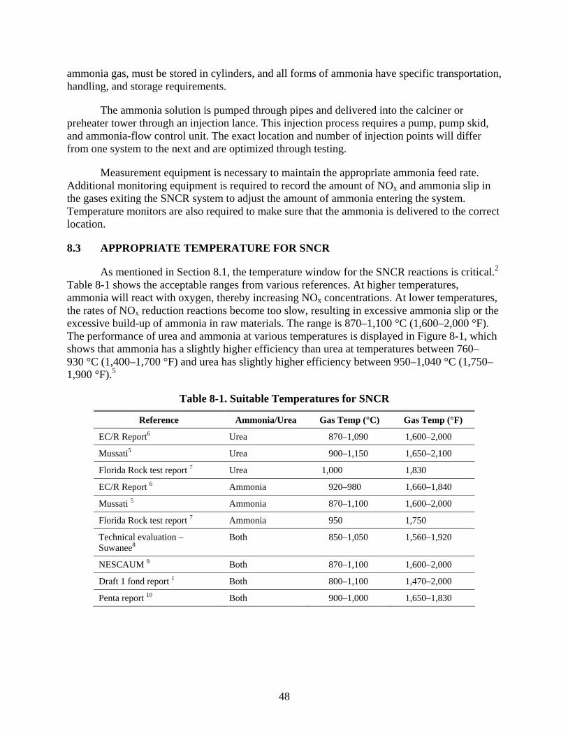
48
ammonia gas, must be stored in cylinders, and all forms of ammonia have specific transportation, handling, and storage requirements.
The ammonia solution is pumped through pipes and delivered into the calciner or preheater tower through an injection lance. This injection process requires a pump, pump skid, and ammonia-flow control unit. The exact location and number of injection points will differ from one system to the next and are optimized through testing.
Measurement equipment is necessary to maintain the appropriate ammonia feed rate. Additional monitoring equipment is required to record the amount of NOx and ammonia slip in the gases exiting the SNCR system to adjust the amount of ammonia entering the system. Temperature monitors are also required to make sure that the ammonia is delivered to the correct location.
8.3 APPROPRIATE TEMPERATURE FOR SNCR
As mentioned in Section 8.1, the temperature window for the SNCR reactions is critical.2 Table 8-1 shows the acceptable ranges from various references. At higher temperatures, ammonia will react with oxygen, thereby increasing NOx concentrations. At lower temperatures, the rates of NOx reduction reactions become too slow, resulting in excessive ammonia slip or the excessive build-up of ammonia in raw materials. The range is 870–1,100 °C (1,600–2,000 °F). The performance of urea and ammonia at various temperatures is displayed in Figure 8-1, which shows that ammonia has a slightly higher efficiency than urea at temperatures between 760–930 °C (1,400–1,700 °F) and urea has slightly higher efficiency between 950–1,040 °C (1,750–1,900 °F).5
Table 8-1. Suitable Temperatures for SNCR
Reference Ammonia/Urea Gas Temp (°C) Gas Temp (°F)
EC/R Report6 Urea 870–1,090 1,600–2,000
Mussati5 Urea 900–1,150 1,650–2,100
Florida Rock test report 7 Urea 1,000 1,830
EC/R Report 6 Ammonia 920–980 1,660–1,840
Mussati 5 Ammonia 870–1,100 1,600–2,000
Florida Rock test report 7 Ammonia 950 1,750
Technical evaluation – Suwanee8
Both 850–1,050 1,560–1,920
NESCAUM 9 Both 870–1,100 1,600–2,000
Draft 1 fond report 1 Both 800–1,100 1,470–2,000
Penta report 10 Both 900–1,000 1,650–1,830
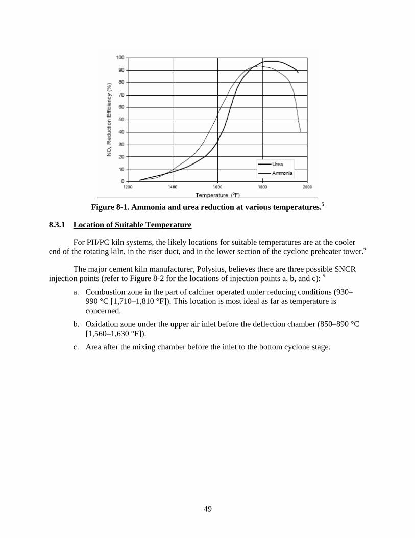
49
Figure 8-1. Ammonia and urea reduction at various temperatures.5
8.3.1 Location of Suitable Temperature
For PH/PC kiln systems, the likely locations for suitable temperatures are at the cooler end of the rotating kiln, in the riser duct, and in the lower section of the cyclone preheater tower.6
The major cement kiln manufacturer, Polysius, believes there are three possible SNCR injection points (refer to Figure 8-2 for the locations of injection points a, b, and c): 9
a. Combustion zone in the part of calciner operated under reducing conditions (930–990 °C [1,710–1,810 °F]). This location is most ideal as far as temperature is concerned.
b. Oxidation zone under the upper air inlet before the deflection chamber (850–890 °C [1,560–1,630 °F]).
c. Area after the mixing chamber before the inlet to the bottom cyclone stage.

50
Optional points for adding SNCR reducing agent
NH3
NH 3 NH3
NH 3
mixing chamber
fuel
tertiaryair
fuelfuel
fuel(kiln inlet)
burnoutair
tertiary air
mixing chamber
meal from preheater
meal from preheater
c b c
a a a
b
Figure 8-2. Possible SNCR injection points.9
8.4 OTHER FACTORS AFFECTING SNCR
Other important design and operational factors that affect NOx reduction by an SNCR system are the following: 10
Residence time available in optimum temperature range Degree of mixing between injected reagent and combustion gases Uncontrolled NOx concentration level Molar ratio of injected reagent to uncontrolled NOx.
8.4.1 Residence Time
Residence time is an important parameter for SNCR performance. Time is required for the following:
Mixing of injected ammonia solutions/urea with flue gas Evaporation of water Decomposition of NH3 to NH2 and free radicals Decomposition of urea to NH3, if urea is used NOx reduction reaction chemistry.
Increasing the residence time available for mass transfer and chemical reactions generally increases the NOx removal. In addition, as the temperature window is lowered, greater residence time is needed to achieve the same NOx reduction level. Residence time can vary from 0.001 to 10 seconds; however, the gain in performance for residence times greater than 0.5 seconds is generally minimal.11 For cement kilns, one source stated that the required residence time is 0.5–1.0 seconds.11 Figure 8-3 below shows the increased performance of SNCR as the residence time is increased.

51
Figure 8-3. NOx reduction and residence time.11
8.4.2 Degree of Mixing 10
For the reduction reaction to occur, the reagent must be dispersed and mixed throughout the flue gas so that there can be contact between the NOx and the reagent. Dispersion must occur rapidly due to the volatility of the ammonia solution. Mixing is performed by the injection system. Injectors (called spray nozzles or lances) atomize the reagent and control the spray angle, velocity, and direction of the injected reagent. To assist in dispersion of aqueous urea, the reagent is atomized into droplets by specially designed nozzles that optimize droplet size and distribution. The location and number of injection points may affect the success of NOx reduction, and these variables should be tested for each kiln system.
Inadequate mixing can be improved by the following:
Increasing energy imparted to droplets Increasing the number of injectors (between one to six nozzles at gas riser) Increasing the number of injection zones Modifying the atomizer nozzle design to improve the solution droplet size,
distribution, spray angle, and direction
8.4.3 Uncontrolled NOx
Reaction kinetics decrease as the concentration of reactants decreases. This is due to thermodynamic considerations that limit the reduction process at low NOx concentrations. For lower NOx inlet concentrations, the optimum temperature for reaction is lower; hence, the percent NOx reduction is lower. Figure 8-4 shows the effect of three different NOx concentrations on the reduction efficiency. At 980 °C (1,800 °F), 54% efficiency is obtained at a 200 ppm concentration; 41% efficiency at 70 ppm; and 12% at 30 ppm.1
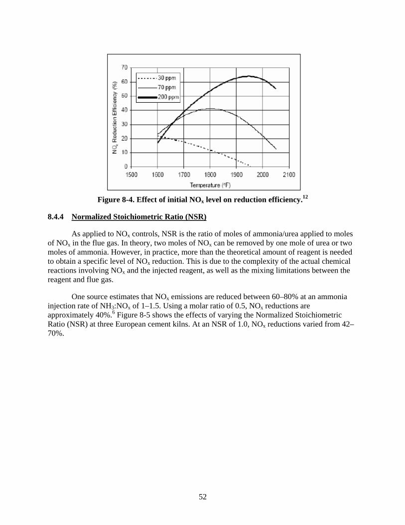
52
Figure 8-4. Effect of initial NOx level on reduction efficiency.12
8.4.4 Normalized Stoichiometric Ratio (NSR)
As applied to NOx controls, NSR is the ratio of moles of ammonia/urea applied to moles of NOx in the flue gas. In theory, two moles of NOx can be removed by one mole of urea or two moles of ammonia. However, in practice, more than the theoretical amount of reagent is needed to obtain a specific level of NOx reduction. This is due to the complexity of the actual chemical reactions involving NOx and the injected reagent, as well as the mixing limitations between the reagent and flue gas.
One source estimates that NOx emissions are reduced between 60–80% at an ammonia injection rate of NH3:NOx of 1–1.5. Using a molar ratio of 0.5, NOx reductions are approximately 40%.6 Figure 8-5 shows the effects of varying the Normalized Stoichiometric Ratio (NSR) at three European cement kilns. At an NSR of 1.0, NOx reductions varied from 42–70%.

53
NOx reduction depending on NH3/NOmolar ratio for precalciner kilns
source: Krupp Polysius AG(ZKG 7/2001)
0
20
40
60
80
100
0 0.2 0.4 0.6 0.8 1 1.2 1.4 1.6NH3/NO molar ratio
NO
X re
duct
ion
[%]
kiln A
kiln B
kiln C
Figure 8-5. Impact of Normalized Stoichiometric Ratio on NOx reduction.9
8.5 POTENTIAL PROBLEMS WITH SNCR
Not all of the ammonia injected into the SNCR system reacts with NOx, and the unreacted ammonia is called ammonia slip. Ammonia in the flue gas stream can have a detectable odor at levels of 5 ppm or greater. Health concerns can occur at ammonia slip levels of 25 ppm or greater. When burning fuels containing chlorine compounds, stack plume visibility problems can occur due to the formation of ammonium chlorides. Limits on ammonia slip are imposed by permits or design requirements. These limits place a constraint on the NOx reduction achieved by an SNCR system.
In addition, operating experience identified several concerns with the build up of ammonium bisulfite scale when burning sulfur-containing fuels.2 Sulfide or elemental sulfur contained in the fuels or raw materials may be roasted or oxidized to SO2 in areas of the pyroprocessing system where sufficient oxygen is present and the material temperature is 300–600 °C (570–1,100 °F). For some cement plants, SO2 is not a problem. Uncontrolled SO2 emissions are only about 0.10 lb/t of clinker and less than 100 t/yr at Florida’s PH/PC kilns because there are minute amounts of sulfur in most of the available limestone. Uncontrolled SO2 can be as much as two orders of magnitude greater when pyritic sulfur is present in raw materials. Unreacted ammonia from the SNCR process or from raw materials reacts with SO2 and SO3 at temperatures prevalent in the upper preheater, pollution control equipment, and outside the stack. Ammonium bisulfate, ammonium sulfate, and ammonium bisulfite may be formed.7

54
When the kiln system is operating with the raw mill on line (the raw mill uses gases from the kiln and clinker cooler to dry the raw materials), the compounds condense and are returned to the feed system and preheater, where they are revaporized. Subsequently, these compounds condense in the raw mill system. When the raw mill is taken off line, the volatile salts are no longer captured in the raw mill and move to the particulate matter (PM) collection device (baghouse or electrostatic precipitator [ESP]). Because the PM control does not capture these new, high concentrations as efficiently, the plume becomes highly visible. When the raw mill is put back into operation, the plume is not visible. This cycle continues indefinitely. It would seem that a filter cake in a baghouse would even out these emissions more so than an ESP, so it is not a foregone conclusion that the plume will be highly visible.
If the plant has a persistent, detached plume due to ammonium sulfate, it is necessary to eliminate ammonia or sulfur dioxide. The obvious method for this is to minimize ammonia use when SO2 emissions are likely.
Operating the raw mill also promotes SO2 removal by limestone scrubbing under humid conditions, due in part to the freshly generated limestone surface produced by grinding. Some of the SO2 generated in the top preheater stages is also scrubbed out by small amounts of free CaO that are carried back from hotter zones by combustion flue gases.
Another SO2 removal technique is to extend the inherent self-scrubbing by CaO that occurs in the calciner to the upper sections of the preheater, where pyrite-derived SO2 is evolved. This involves conveyance of CaO from the calciner to the upper stages of the preheater, which consists of a cyclone and some ductwork and no moving parts.
If these three SO2 measures are insufficient, then conventional wet or dry scrubbers can be considered. The Texas Commission on Environmental Quality estimated that the TXI Midlothian scrubber cost $13 million. SO2 emissions were permitted at 1.33 lb/t of clinker, but it is not certain whether SO2 emissions are that high. If they are that high and an SNCR system is installed, it might be necessary to limit ammonia slip or to further enhance SO2 removal to avoid a detached plume.
A very fine suspension of slaked CaO can be introduced into gas-conditioning tower to remove SO2, particularly when the raw mill is not operating. The droplets react, dry, and are captured by the PM controls, where the excess CaO (from the dried droplets) will continue to remove the remaining SO2.7
8.6 SNCR EXPERIENCE
8.6.1 United States – Early Tests
According to EPA’s NOx ACT reports, there was very limited experience with SNCR at cement kilns; however, two U.S. plants that were tested with SNCR systems and that are mentioned in these reports are discussed below.
55
8.6.1.1 Ash Grove Cement - Seattle, Washington13
A week-long test of a Nalco Fuel Tech (urea) system at the Ash Grove Cement plant in Seattle, WA, was performed in October 1993. This test was conducted on a 160 tons per hour (t/hr) 5-stage PH/PC kiln under 10 different operating conditions representing a wide range of fuel firing and excess air conditions. The urea-based system was easily installed at the plant using an existing port and available resources without a plant outage. Plant operation was unaffected during testing. A commercial system should also be easily adapted to plant operations and easily maintained. The NOx emission limit (422 lb/hr or 2.6 lb/t) was maintained under various kiln/calciner operating conditions.
The urea reagent was injected at three ports at the top of the calciner, three ports halfway up the calciner, and four ports at the bottom of the calciner. During the test, the kiln feed rate was steady at 100 t/hr, and the kiln was fired with natural gas. As a result of the injections, NOx emissions were reduced from 350–600 lb/hr to less than 100 lb/hr. The NOx reduction was greater than 80% for most cases, and chemical utilization of urea was greater than 50%. These excellent results were attributed to a high degree of mixing and a long residence time at an appropriate temperature in the preheater tower. The average ammonia slip was 4 ppm above baseline at an NSR of 1.
When firing gas into the kiln and coal in the calciner, uncontrolled NOx emissions averaged 2.8 lb/t of material input. When gas was fired in both units, uncontrolled NOx emissions were 2.9 lb/t of clinker. Based on limited short-term data using stabilized urea, NOx was reduced by ~27% at an NSR of 0.5 and by ~55% at an NSR of 1.0.14 At an NSR of 1.5, the NOx reduction was as high as 80%, and chemical utilizations were higher than 50%. At an NSR of 2, a 90% reduction of NOx was obtained. The EC/R report indicates that under 10 different operating conditions at this same kiln, NOx was reduced from 3.5–6.0 lb/t of clinker to less than 1 lb/t clinker.6
SO2 and CO were unchanged from baseline levels at an NSR < 0.7. At a higher NSR, these emissions also remained near baseline levels when the preheater oxygen concentration was > 2.3%. However, both SO2 and CO increased slightly with increased chemical injection rates at lower oxygen. Ammonia at the exit of the preheater was erratic, ranging from 6 ppm under baseline to 10 ppm at an NSR of 1.
8.6.1.2 LaFarge – Davenport, Iowa
A NOxOut® system (urea) was tested in October 1998 at LaFarge’s plant in Davenport, IO. Much lower NOx reductions were obtained (10–20% from uncontrolled emissions of 350 lb/hr) at the LaFarge plant, the reasons for which are presented below.15
The LaFarge plant is unusual due to the high proportion of heat released in the plant’s calciner. Most PH/PC kilns supply 50% of heat input to the calciner. Unlike the Ash Grove plant, where only 5–10% of heat input is added at the calciner, 70% heat input is added at the calciner at the LaFarge plant. This difference affects the gas temperature in the calciner and the gas-retention time in the 860–1,090 °C (1,600–2,000 °F) range where SNCR is effective. The flue gas in the Ash Grove system stayed within this range for a longer time, and the gas retention

56
time in the calciner was 2.7 seconds compared to 1.95 seconds at the LaFarge plant. The LaFarge unit operates at 815–920 °C (1,500–1,700 °F), and Ash Grove operates at 840–1,130 °C (1,540–2,070 °F); thus, the Ash Grove unit has a larger window within this range.
In addition, a significant portion (40–60%) of the kiln flue gas at LaFarge is bypassed prior to the calciner; therefore, roughly half of the kiln exhaust gas is not treated by SNCR. Raw material at the LaFarge plant is highly alkaline (e.g., sodium, potassium) compared to the material processed at the Ash Grove plant. The LaFarge alkali bypass provides the ability to control alkali content of the clinker product; thus, anticipated SNCR control should be much less than 30–70% because roughly 50% of the kiln’s flue gas was not treated by SNCR. The gas exit temperature of the bypass gas is 920 °C (1,700 °F), but is immediately quenched by adding dilution air to 430–780 °C (800–900 °F). There is not sufficient time for the addition of SNCR to this gas stream (the alkali bypass stream). Data during the Fuel Tech tests in October 1998 indicate that approximately one-third of uncontrolled stack emissions are from the bypass.
Another reason why SNCR was not effective at La Farge was due to the PH/PC temperature profiles.16 No section of the calciner had an ideal temperature profile for SNCR. The reagent injection is at the top of the preheater (after the Stage 4 cyclone), where the temperature is around 890 °C (1,640 °F). The temperature drops by 90–120 °C (200–250 °F) over the next 1.3 seconds as gases pass through the Stage 4 cyclone. Thus, the temperature is marginally within the SNCR window and there is a slight NOx reduction. Ammonia slip was 14 ppm from the 5–6 ppm baseline. Flue gases have cooled well below the SNCR temperature window; therefore, no reduction was found. Ammonia slip was 47–52 ppm.17 The optimal SNCR temperature window is 860–1,090 °C (1,600–2,000 °F); however, this window only appears in the upper calciner/lower Stage 4 cyclone zone of the LaFarge kiln system. The temperature in this zone of the LaFarge kiln system ranges from 860–920 °C (1,600–1,700 °F), with a residence time of less than two seconds. At LaFarge, the temperature of flue gas in the riser between the kiln exit and the bottom of calciner is 815 +/-10 °C (1,500+/-50 °F). The peak temperature in the calciner is 920 °C (1,700 °F), and the temperature at the exit of calciner is 890 °C (1,640 °F). The gas residence time in the calciner is 1.95 seconds. Flue gases exit the calciner and enter the Stage 4 cyclone preheater (taking 1.3 seconds).17
By comparison, at Ash Grove, the combustion gas from the kiln enters the bottom of the calciner at 1,120 °C (2,070 °F). The gas temperature at the top of the calciner is 830 °C (1,540 °F). The horizontal temperature profiles were essentially flat, with less than a 8 °C (15 °F) variation across the preheater cross section. The estimated residence time in the calciner is 2.7 seconds. After leaving the kiln, the maximum temperature reached by the flue gas is 920 °C (1,700 °F) at the middle of the calciner, very near the combustion zone. Results for the Ash Grove and LaFarge pilot tests are summarized in Table 8-2.

57
Table 8-2. Summary of Pilot Test Results for Ash Grove and LaFarge
Parameter Ash Grove, Seattle, WA LaFarge, Davenport, IA
NOx Reduction (%) 27, 55, 80 (at NSR of 0.5, 1.0, 1.5, respectively)
10–20
Heat input to precalciner (%) 5–10 70
Alkali bypass (%) 0 40–60
Gas residence time for SNCR reaction (sec) 2.7 1.95
8.6.2 U.S. Plants Presently Using or Installing SNCR
8.6.2.1 Hercules Cement – Stockertown, PA (Using SNCR)
The oldest existing, full-scale SNCR installation on a cement kiln presently operating in the United States is located at Hercules Cement in Stockertown, PA. This SNCR system uses a 19% ammonium hydroxide solution (AHS) and was installed in 2001 on kiln #3 (a PH/PC kiln). Kiln #3, also equipped with LNB, accounts for 60% of the cement production at this plant.18
The Hercules Cement SNCR system was installed to comply with RACT levels, and NOx reductions of 25% (300 ppm) have been achieved using this system. The reduction rates of 11.5% are sustainable, and the system has no impact on clinker production.19
Tests in 2003 show ammonia emissions to be 13 ppmdv (28 ppmvd @ 7% oxygen). If a good spot for injecting the AHS into Kiln #1 can be found, an overall reduction of 40–50% at the stack may be seen. The annual cost for AHS is $20,000-35,000.18
The ammonia injection for the Hercules Cement PH/PC kiln is near the bottom of the calciner rather than at the 180 degree bend before the bottom cyclone. This location is better because of its low CO and maximum oxygen, because the ammonia does not have to compete with CO for available OH radicals. SNCR performance might also be limited by the possibility of a detached plume if there are pyrites in the raw material.20
8.6.2.2 St Mary’s Cement – Charlevoix, MI (Using SNCR)
An SNCR system was temporarily installed on the PH/PC kiln system at the St. Mary’s Cement plant in Charlevoix, MI, and pilot tests were conducted in April of 2005. The SNCR system was utilized through the 2005 ozone season. The plant is in the process of permanently installing an SNCR (urea) system. According to State of Michigan personnel, the permanent SNCR system is being installed to comply with Michigan NOx Rule 801, which sets a limit of 6.5 lb/t of clinker (30-day rolling average) during the ozone season.20, 21 The kiln was originally a long wet kiln that was modified to a PH/PC kiln in 1977.
Daily averages for the period May 1–September 30, 2005, were obtained from the State of Michigan. The 30-day rolling averages beginning May 30, 2005, range from 4.41–6.38 lb/t of clinker for this period. Clinker production varied between 716 and 4,516 t/day, and there were 11

58
days during this period when the kiln did not operate. Most days, the production range for clinker varied between 3,800 and 4,500 t/day.22
According to plant personnel, the St. Mary’s plant uses a 40% urea solution. The kiln has a lot of up and down operations and operates typically at about 70–80% capacity during the ozone season. The calciner and kiln are both permitted to burn coal, and there is a test trial permit for the firing of petroleum coke. This trial will dictate what percentage of coke will be burned in the system. There is also a 10–30% alkali bypass on the St. Mary’s system. The urea solution is currently injected above the kiln feed shelf and before the calciner. Other locations for injections were tested, such as after the calciner and at the upper stage and entrance of the calciner, but optimum efficiency was obtained at the present location.23
8.6.2.3 Cemex - Brooksville, Florida (Using SNCR)24
Cemex has installed an SNCR system on two existing preheater kilns (not PH/PC kilns) in Brooksville, FL. An SNCR system is presently operating on one of the two kilns, and the other kiln will start operating SNCR after obtaining a permit to test tires and petroleum coke as fuels. The Cemex SNCR system uses a 19% ammonia solution with one injection nozzle at the kiln inlet, where the optimum temperature for ammonia (850–1,150 °C [1,550–2,100 °F]) is available. The oxygen content is typically 1.5–2.0% at this location. There are also three injection nozzles in the riser duct, but these are not used.
The ammonia solution injection rate for the single injection point can vary from 0–15 liters per minute or up to 0.35 lb-moles of ammonia per minute. Assuming an ammonia utilization rate of 75%, based on other tests in Florida, equates to a potential NOx reduction of up to 15 lb-moles/hr. A NOx reduction of about 4–5 lb-moles/hr equates to a NOx reduction from the present maximum rate of 4.0 lb/t of clinker to the proposed emission rate of 2.0 lb/t of clinker; therefore, there is assurance that the SNCR system is capable of delivering the required ammonia. The molar ratio for this reduction is 0.6–0.7.
Cemex plant operators believe that, even with the potentially greater NOx emissions during the firing of petroleum coke or coke/coal mixture, there is sufficient ammonia delivery capability with the single injection point to achieve 2.0 lb/t of clinker.
As noted previously, preheater kilns are less fuel efficient that PH/PC kilns. In addition, all fuel is burned at the main kiln burner in a preheater kiln, so a great deal of thermal NOx is produced. The uncontrolled emission rate for preheater kilns is also higher than for PH/PC kilns as shown in Table 6-1.
According to the state agency, the two kilns in 2007 achieved about 2.0 lb/t of clinker. Ammonia injection has increased because the kiln was not fully converted to indirect firing when a new low NOx burner was installed. Cemex plant operators plan to complete the conversion to indirect firing over the next year, which is expected to improve the plant’s process control and require less ammonia injection.25
The plant submitted plans for a third PH/PC kiln, but decided not to go forward with its construction. The kiln was to burn up to 100% petroleum coke. The draft BACT determination by the Florida Department of Environmental Protection would require a limit of 1.5 lb/t of
59
clinker on a 30-day basis. More information is available at www.dep.state.fl.us/Air/permitting/ construction/cemex/TEPD.pdf.25
8.6.2.4 Holcim, Midlothian, Texas (Using SNCR)26–30
The Holcim plant in Midlothian, TX, operates two PH/PC kiln lines. Line 1 was commissioned in 1987, and Line 2 was commissioned in March 2000. The plant exceeded 1998–99 NOx permit limits and was therefore required to test SNCR. The permit limit was 1,659 t/yr for the combined kilns.
Line 2 has an LNB in the kiln, an MSC, and provisions for alternative fuels. Line 1 uses alternative fuels, but does not have an LNB or SCC. Wet scrubbers were added to both lines and were predicted to remove 25% of NOx based on European operations. However, in the United States, most NOx emissions from cement kilns are NO, so little reduction using this scrubber was obtained.
The SNCR system (using a 19.5% ammonia solution) was tested on both lines in 2005. For both lines, the ammonia solution was injected at the point where the temperature was approximately 900 °C (1,650 °F). For Line 1, the injection location was the riser duct after the calciner and before the bottom-stage cyclone. For Line 2, the selected injection point was on the riser duct after the tertiary air input and before the calciner. These locations were optimal with regard to temperature, retention time, and cross-sectional spray distribution.31 The entire airflow was tested at full load conditions and at all operating parameters (e.g., mill-up/down, scrubber-up/down). The test period was approximately two weeks per line. On a routine basis, Line 1 achieved a 40–45% reduction, and Line 2 achieved a 30–40% reduction. These numbers only establish SNCR “applicable” and “effective” levels. The NOx reduction was as high as 80%, but at this reduction, there was excessive ammonia slip and pluggage at the preheater.
According to Holcim personnel, full-scale SNCR systems began operating on April 15, 2006, on Lines 1 and 2. The ammonia solution was added at the top of the preheater for Line 1 and at the top of the pyroclone for Line 2.31
Table 8-3 summarizes curves prepared on the performance of the SNCR systems for the two Holcim lines. The SNCR testing commenced with a molar ratio of 0.4 and increased. No significant change in CO was observed during the SNCR testing; however, a general increase in ammonia emissions was observed. A plug formed at the top of the Line 1 preheater tower following testing at molar injection rates greater than 1.0. It is unknown if this plugging was directly related to the increase of molar ratio or was a gradual, continuous process of ammonium sulfate and ammonium bisulfate deposition in the preheater tower.
Table 8-3. NOx Reductions (%) for Lines at Holcim, Midlothian, Texas
Line NSR- 0.4 NSR- 0.6 NSR- 0.7 NSR- 1.0
1 30 43 47 60*
2 10 28 32 45*
* Sharp increases in NH3 emissions

60
The new NOx permit limits for the combined kilns are 3,738 t/yr and 1,300 lb/hr. During the ozone season (May 1– September 30), NOx must not exceed 1,564 tons for the combined kilns. Additional SNCR testing was conducted in 2006 and will continue in 2007 and may result in changes to the NOx permit limits.
8.6.2.5 Holcim – Lee Island, Missouri (Installing SNCR)
Construction of this new Holcim plant began in summer 2006, and the expected completion date is 2008–2009. The annual clinker production capacity of the new plant will be 4.828 million tons, using one PC/PH kiln system.32
An SNCR system is to be installed as innovative control technology no later than 24 months after the plant commences operation. After the installation of the SNCR system, NOx emissions on 12-month rolling operation will be less than 1,322.8 lb/hr and 2.4 lb/t of clinker. There will also be a summer season (May 1 to September 30) NOx emission limit of 1,622 tons. This limit includes 530 t/yr of emission-reduction credits. In no case shall NOx emissions exceed 1,822 tons of NOx for the summer season from the ILC and raw mill system.33
Plant operators have recently contracted with FLS to install an FLS calciner. FLS will design the kiln to achieve 1.6 lb/t of clinker during the ozone season to avoid the possibility of required production reduction to meet the seasonal tonnage.25 The emission limit is in tons rather than in lb NOx/t clinker so that the plant could use controls or reduce production, or a combination of the two, to comply with the emission limit.34
8.6.2.6 Lehigh Portland Cement – Mason City, Iowa (Using SNCR)
An SNCR demonstration test was done on PH/PC kiln #8 at Lehigh Portland Cement in Mason City, IO. Lehigh’s kiln #8 is equipped with LNB and has a capacity of 1,050,000 t/yr. Other existing controls include an ESP for PM and a scrubber for SO2. During stable operation, the SNCR system reduced NOx emissions by 22%. The molar ratio data used during this test are considered confidential business information.
The SNCR system was required to be installed as BACT in a 2004 prevention of significant deterioration (PSD) permit. The Iowa Department of Natural Resources (DNR) concluded that the plant was capable of installing SNCR as a retrofit technology as part of a major plant upgrade. The precalciner vessel was replaced by a larger vessel, and all of the four stage cyclones were replaced with a larger, more efficient vessel.16
The SNCR system was installed in late 2005. A 180-day shakedown period has been completed, and compliance was being achieved. The Fuel Tech urea reagent is injected in two locations – two injectors at the crossover duct and five injectors at the top of the calciner. The SCNR system is operated year round.
The NOx emission limit is 2.85 lb/t of clinker (30-day rolling average), a 25% reduction due to SNCR. Therefore, uncontrolled NOx is 3.8 lb/t of clinker. In addition, there is a calendar monthly average limit of 5 lb/hr. The calciner burns fuel in substoichiometric conditions.35
61
8.6.2.7 Drake Cement – Arizona (Installing SNCR)
A proposed Drake Cement plant is expected to be constructed and commence operation in 2008. The nominal capacity of the PH/PC kiln system is 660,000 t/yr. The system will be a rotary kiln, 6-stage preheater, low NOx calciner with a clinker production of 2,000 t/day. The maximum capacity of the plant will be 83 T of clinker/hr, and the kiln will operate 7,920 hrs/yr. The rotary kiln and calciner will burn coal, which will be less than 0.90 weight percent sulfur. The raw limestone will have a total sulfur content < 0.01 weight percent. Fuel combustion in the calciner will be 50–55% of the total energy demand of the PH/PC kiln system; the energy demand of the rotary kiln will be 45–50%. There will be low sulfur in the raw material. One ton of raw feed material requires 0.0765 tons of coal. Approximately 1.53 tons of raw materials are required to produce one ton of clinker.36
The air permit application submitted in June 2004 proposed an emission limit of 2.3 lb/t of clinker on a 24-hr basis. The controls to be used include LNBs in the kiln, a low NOx calciner, and MSC. The draft permit issued by the State of Arizona has a BACT limit of 1.95 lb/t of clinker (30-day rolling average).36 For the first 180 days after initial startup of the rotary kiln, the NOx emission limit will be 2.45 lb/t of clinker on a daily rolling 30-day average. To comply with Class I considerations, the limit is 95 lb/hr on an hourly 24-hr average. Using the maximum production rate of 83 t/hr of clinker, this is equivalent to 1.14 lb/t of clinker vs. 1.25 lb/t clinker by SNCR. This suggests that BACT is not necessarily the lowest limit for NOx when there are other issues to consider, such as visibility.36
It is expected that the reagent injection (ammonia in an aqueous solution) will be introduced in the space between the calciner and the bottom stage of the preheater, which has a temperature window of 860–980 °C (1,580–1,800 °F).
As described in an Innovative Control Technology analysis, Drake intends to reduce NOx emissions to 416 t/yr, with a voluntary limit that has been proposed as result of Air Quality Impact Analysis. Drake also proposes to add SNCR in conjunction with the currently proposed BACT limit.
To meet the voluntarily accepted, modeling-driven limit, Drake plans to optimize SNCR systems and other process and air pollution control equipment to minimize NOx emissions. If these operations do not reduce NOx to 416 t/yr, Drake will curtail production to ensure that 416 t/yr is not exceeded during any 12-month period.
With a six-stage PH/PC process and a low NOx calciner (i.e., offering multistage or stageless combustion and sufficient residence time), the NOx emission rate is estimated to be 1.9–2.3 lb/t of clinker. According to its Class 1 application, Drake Cement’s use of these combustion design features will deliver an emission rate that satisfies BACT requirements. The NOx concentration leaving the calciner and entering the SNCR will not be as high as plants using current combustion technology. This has the benefit of reducing the additional NOx reduction by SNCR that is necessary to achieve the proposed emission limit of 95 lb/hr. Therefore, the portion of overall NOx reduction attributable to SNCR is within current process capabilities with respect to both relative proportion (percent controlled) and absolute magnitude (lb/hr removed).37
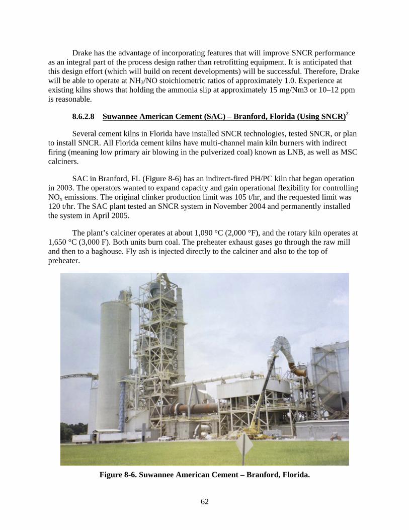
62
Drake has the advantage of incorporating features that will improve SNCR performance as an integral part of the process design rather than retrofitting equipment. It is anticipated that this design effort (which will build on recent developments) will be successful. Therefore, Drake will be able to operate at NH3/NO stoichiometric ratios of approximately 1.0. Experience at existing kilns shows that holding the ammonia slip at approximately 15 mg/Nm3 or 10–12 ppm is reasonable.
8.6.2.8 Suwannee American Cement (SAC) – Branford, Florida (Using SNCR)2
Several cement kilns in Florida have installed SNCR technologies, tested SNCR, or plan to install SNCR. All Florida cement kilns have multi-channel main kiln burners with indirect firing (meaning low primary air blowing in the pulverized coal) known as LNB, as well as MSC calciners.
SAC in Branford, FL (Figure 8-6) has an indirect-fired PH/PC kiln that began operation in 2003. The operators wanted to expand capacity and gain operational flexibility for controlling NOx emissions. The original clinker production limit was 105 t/hr, and the requested limit was 120 t/hr. The SAC plant tested an SNCR system in November 2004 and permanently installed the system in April 2005.
The plant’s calciner operates at about 1,090 °C (2,000 °F), and the rotary kiln operates at 1,650 °C (3,000 F). Both units burn coal. The preheater exhaust gases go through the raw mill and then to a baghouse. Fly ash is injected directly to the calciner and also to the top of preheater.
Figure 8-6. Suwannee American Cement – Branford, Florida.

63
According to plant personnel, the advantages of using SNCR are the following: 37
Greater kiln stability Prolonged periods of increased production Fewer kiln process problems (build-up in riser duct) Reduced NOx Possibility to use petroleum coke with current NOx limits.
The disadvantages of using SNCR are the following:
Higher than average CO Ammonia emissions observed during raw mill offline periods. Ammonia emissions
may occur over longer periods of time when the raw mill system is operational.
In selecting where to inject the ammonia solution, it is important to separate the NO reduction reaction from combustion. This is ensured when the ammonia solution injection is done as close as possible to the bottom-stage cyclone. The actual injection location where ammonia was injected at the SAC plant is shown in detail in Figures 8-7 and 8-8 (Figure 8-7 also shows one of the four injection ports). The injection nozzle is shown in Figure 8-9.38
Figure 8-7. SNCR injection location – Suwannee American Cement,
Branford, Florida.

64
Figure 8-8. Ammonia injection, Suwannee American Cement.
The ammonia injection location was verified through previous testing in recent years by Polysius on kilns in Europe similar to the SAC PH/PC kiln. The location is in the later portion of the calciner prior to the Stage 1 (lowest) cyclone and just beyond the MSC deflection chamber. This location has been demonstrated as the best location for Polysius MSC and MSC-combustion chamber kilns. Temperatures at this location were verified prior to testing and ranged from 870–910 °C (1,600–1,675 °F), with oxygen around 2%. This location provided optimal residence time at the needed temperature and oxidizing atmosphere, as well as the necessary turbulence for mixing the ammonia solution.39

65
Figure 8-9. Suwannee American Cement ammonia injection nozzle.
At the injection location, gas temperatures averaged 860 °C (1,580 °F), which is at the low end of the temperature range for SNCR. When temperatures are at the lower end of range, CO emissions are minimal. When temperatures are in the higher end of range, reactivity of NH2 improves, but CO emissions after the injection are much higher. In addition, if ammonia is injected in too high temperature gases, NO molecules may form instead of N2.38
Full-scale SNCR tests were conducted on the existing kiln. There was no problem reaching 2.0 lb/t of clinker (29–33% control efficiency) while operating at 3.0–3.5 lb/t of clinker at kiln exit. The SNCR, in conjunction with MSC and separately from MSC was also tested, and both worked fine.
For two days prior to ammonia injection, normal NOx emissions while utilizing MSC in conjunction with LNB resulted in NOx emissions of 2.4–2.5 lb/t of clinker. SAC utilizes the MSC and the combustion chamber to create reducing conditions and frequently encounters process problems caused by this type of operation, such as strong reducing conditions and high CO at kiln inlet. Most typically, the problems consist of solids build-up in riser duct (lowest portion of the calciner prior to the entrance of the kiln). While establishing the baseline, SAC experienced some operational problems, as indicated by abrupt changes in clinker production, which signify process upsets or problems; however, overall operations were satisfactory.39
Based on testing, the following conclusions were reached:
NOx emissions of 2.0 lb/t of clinker or below were achieved with SNCR with and without MSC. Increased process stability was realized during both testing periods,
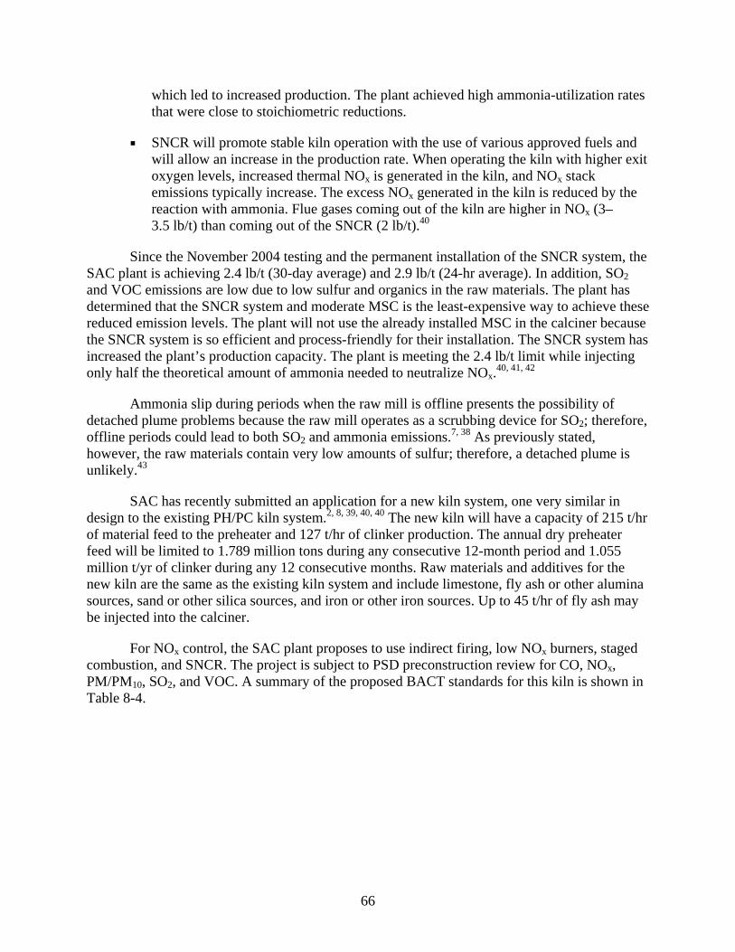
66
which led to increased production. The plant achieved high ammonia-utilization rates that were close to stoichiometric reductions.
SNCR will promote stable kiln operation with the use of various approved fuels and will allow an increase in the production rate. When operating the kiln with higher exit oxygen levels, increased thermal NOx is generated in the kiln, and NOx stack emissions typically increase. The excess NOx generated in the kiln is reduced by the reaction with ammonia. Flue gases coming out of the kiln are higher in NOx (3–3.5 lb/t) than coming out of the SNCR (2 lb/t).40
Since the November 2004 testing and the permanent installation of the SNCR system, the SAC plant is achieving 2.4 lb/t (30-day average) and 2.9 lb/t (24-hr average). In addition, SO2 and VOC emissions are low due to low sulfur and organics in the raw materials. The plant has determined that the SNCR system and moderate MSC is the least-expensive way to achieve these reduced emission levels. The plant will not use the already installed MSC in the calciner because the SNCR system is so efficient and process-friendly for their installation. The SNCR system has increased the plant’s production capacity. The plant is meeting the 2.4 lb/t limit while injecting only half the theoretical amount of ammonia needed to neutralize NOx.40, 41, 42
Ammonia slip during periods when the raw mill is offline presents the possibility of detached plume problems because the raw mill operates as a scrubbing device for SO2; therefore, offline periods could lead to both SO2 and ammonia emissions.7, 38 As previously stated, however, the raw materials contain very low amounts of sulfur; therefore, a detached plume is unlikely.43
SAC has recently submitted an application for a new kiln system, one very similar in design to the existing PH/PC kiln system.2, 8, 39, 40, 40 The new kiln will have a capacity of 215 t/hr of material feed to the preheater and 127 t/hr of clinker production. The annual dry preheater feed will be limited to 1.789 million tons during any consecutive 12-month period and 1.055 million t/yr of clinker during any 12 consecutive months. Raw materials and additives for the new kiln are the same as the existing kiln system and include limestone, fly ash or other alumina sources, sand or other silica sources, and iron or other iron sources. Up to 45 t/hr of fly ash may be injected into the calciner.
For NOx control, the SAC plant proposes to use indirect firing, low NOx burners, staged combustion, and SNCR. The project is subject to PSD preconstruction review for CO, NOx, PM/PM10, SO2, and VOC. A summary of the proposed BACT standards for this kiln is shown in Table 8-4.

67
Table 8-4. BACT Determinations – Suwannee American Cement, Branford, Florida, 11/05 8
Pollutant Emission Standards (lb/t) Emission
Standards (lb/hr) Averaging Time CO 2.90 368 30-day rolling average – CEMSNOx 1.95 248 Same as above NOx (initial startup) 3.0 381 Same as above PM/PM10 0.10
(of dry preheater feed material) 21.5 Average of 3 - 1hr test runs
10% opacity 6-minute average w/ COMS SO2 0.20 25.4 24-hr rolling CEMS average VOC 0.12 15.2 30-day block CEMS average
8.6.2.9 Florida Rock Industries (FRI) – Newberry, Florida (SNCR Installed for Testing)
The FRI plant in Newberry, FL installed SNCR for testing purposes; however, SNCR is not being presently used because the kiln can achieve low NOx levels with MSC. This modern PH/PC kiln was designed by Polysius and is shown in Figure 7-4. The FRI plant has a permitted clinker production rate of 2,650 t/day (110 t/hr), and both the kiln and the calciner are fired with coal. The kiln uses air and fuel staging on a Polysius MSC ILC. The calcination burner is mounted horizontally rather than in a separate combustion chamber, and provisions are included for a small burner in the kiln inlet housing. Instead of using a burner at the kiln inlet, FRI burns tires. Full-scale SNCR tests were conducted on the SNCR system on this existing kiln. The kiln had no problem reaching 2.0 lb/t. The December 2004 testing is described in detail in the sections below.7 Tables 8-5 and 8-6 summarize the emission test results.
Table 8-5. Emission Test Results with Tires – Florida Rock Industries, Newberry, Florida, 12/04 7
Uncontrolled NOx (lb/t)
Controlled NOx (lb/t)
Molar Ratio (NH3/NOx)
NOx Reduction (%)
3.1 2.1 0.12 34
2.9 1.8 0.19 39
3.2 2.1 0.25 35
3.3 1.5 0.51 54
3.3 1.1 0.64 68
3.2 2.0 0.34 39
68
Table 8-6. Emission Test Results without Tires – Florida Rock Industries, Newberry, Florida, 12/04 7
Uncontrolled NOx (lb/t) Controlled NOx (lb/t) Molar Ratio(NH3/NOx) NOx Reduction (%)
4.5 4.2 0.09 7
4.2 3.5 0.21 18
3.7 2.6 0.35 29
3.6 1.9 0.47 47
3.6 0.9 0.80 76
3.2 0.6 1.04 82
At lower molar ratios (< 0.5), NOx efficiency was greater when tires were burned as fuel compared to the efficiencies when tires were not burned. At molar ratios of ~0.5, 50% control was achieved with or without burning tires. These data also show that NOx is reduced by approximately 0.8 lb-moles with the injection of 1.0 lb-mole of ammonia (ammonia utilization rate of 80%) without burning tires.
FRI plans to install a new PH/PC kiln in a couple of years.44 The new kiln will be a Polysius MSC system and will use an SNCR system in conjunction with MSC. The issued permit information shows that the new kiln will have a capacity of 206 t/hr of material feed, dry basis, to the preheater; 125 t/hr of clinker production; and 138 t/hr of Portland cement production.
The NOx emission limit will be 1.95 lb/t (243.8 lb/hr) on a 30-day rolling average. For the first 180 operating days, the kiln cannot exceed 2.4 lb/t (30-days rolling average). As the project was subject to PSD review and BACT determinations for NOx, PM, PM10, SO2, CO, and VOC, the other limits are the following:
PM - 0.23 lb/t PM10- 0.20 lb/t SO2 - 0.23 lb/t CO - 3.6 lb/t VOC - 0.12 lb/t Hg - 122 lb/yr
8.6.2.10 Rinker/Florida Crushed Stone, Brooksville, Florida (SNCR Proposed)45
This facility is planning a new line that is expected to be completed by 2007. It will have a capacity of 206 t/hr of material feed, dry basis, to the preheater and 125 t/hr of clinker production.
The NOx emission limit will be 1.95 lb/t (243.8 lb/hr) on a 30-day rolling average. The project was subject to PSD review and BACT determinations for NOx, PM, PM10, SO2, CO, and VOC. These limits are the following:
PM - 0.23 lb/t PM10- 0.20 lb/t
69
SO2 - 0.23 lb/t CO - 3.6 lb/t VOC - 0.12 lb/t Hg - 122 lb/yr
The proposed NOx control is an SNCR system with MSC. The SNCR will operate in conjunction with MSC (including reducing conditions at the calciner, as needed).
8.6.2.11 Sumter Cement Company – New Center Hill, Florida (SNCR Planned)8
Sumter Cement is planning to construct a new PH/PC kiln system with a capacity of 353 t/hr as feed to the preheater, resulting in 208 t/hr of clinker production. The expected operating hours are 7,883 hrs/yr. Raw materials and additives to the kiln will include limestone, fly ash, sand, and steel slag. Fly ash can be injected through the calciner burner. There will also be an in-line raw mill that simultaneously dries raw materials using the exhaust gas from the kiln, calciner, and clinker cooler.
The calciner will be designed to accommodate the introduction of fly ash and non-hazardous waste through the calciner burner. The burner will contain a specific chamber or nozzle within the burner for the simultaneous introduction of coal, petroleum coke, fly ash, and non-hazardous wastes. Petroleum coke typically has a lower reactivity and requires the longest retention time in the calciner.
Tires, either whole or shredded, may be used and injected via an airlock/gate system into the material inlet of the kiln. The tires produce a localized reduction zone around the tire fuel, which assists in NOx reduction. The proposed tire gasification system would produce a combustible gas that would be injected into the kiln inlet or calciner region.
The primary fuel-firing scenario has 55–60% of total heat input in the calciner and 40–45% in the kiln main burner. This ratio will remain fairly constant. When tires are used, they may account for up to 15% of the heat input to the calciner. When using tire gasification, up to 40% of the calciner fuel may be supplied from tires.
The primary fuel for kiln and calciner burners will be ground bituminous coal and petroleum coke. Burners will be designed to burn non-hazardous liquids (e.g., fuel oil), which could produce up to 50% of total heat input in each burner. Solid nonhazardous waste may be used in the calciner burner and produce up to 50% of the total heat input.
To control NOx, the plant will use a form of MSC (i.e., reducing zone), LNBs in the kiln, and SNCR. The Florida DEP determined that 1.95 lb/t (30-day rolling average) is the BACT level for this project.
8.6.2.12 American Cement Company – Sumterville, Florida (SNCR Planned)46
Proposed BACT determined by the Florida DEP for this planned PH/PC kiln system is 1.95 lb/t (30-day rolling average). NOx controls will be SNCR, LNBs in the kiln, kiln design, and MSC. MSC will be used to function with either fuel staging or combustion air staging and will

70
have flexibility in meal splitting. Kiln design refers to the PH/PC kiln system. The plant is designed for a clinker production of 1,150,000 t/yr.
Coal and petroleum coke will be burned in both the kiln and the calciner. The ratio of coal to petroleum coke burned will depend on process conditions, such as the material build-up, feed alkali content, and heating value of the fuel. Petroleum coke will not exceed 25–30% of petroleum coke/coal fuel mix.
Field tests by Polysius, demonstrated that a 65–70% NOx reduction was achieved using a 25% ammonia water solution at a molar ratio of 1. In comparison, a 68% urea solution achieved only a 35–40% reduction at the same molar ratio. At a higher molar ratio than 1, ammonia slip becomes a problem.47
8.6.2.13 Dragon Products Company – Thomaston, Maine (Installing SNCR)48, 49, 50
NOx emissions from Dragon’s Thomaston, Maine facility were closely approaching their permit limit. To avoid exceeding their limit, the company decided to install an SNCR system on their dry kiln. The SNCR and kiln system are currently in a testing program and should be in operation in 2007. Pilot tests of the SNCR performed in November 2006 showed ammonia slippage of 10.3 ppm at 7% O2 (3.24 lb NH3/hr) with the raw mill on and 22.5 ppm at 7% O2 (6.9 lb NH3/hr) with the raw mill off. NOx CEM data was not available for the period when these tests were being conducted. A NOx limit of 1,533 tons/yr and an annual production rate of 766,500 tons of clinker per year equates to an ouput-based limit of 4.0 lb NOx per ton of clinker. The part 70 air emission permit for Dragon is available at http://www.maine.gov/dep/air/licensing/ TitleVlicenses/a326ai.pdf.
8.6.2.14 Cemex – New Braunfels, Texas (Installing SNCR)
A new kiln line will produce up to 3,600 t/day clinker. The company has agreed to install SNCR on both of their two kiln lines.26
8.6.3 SNCR – Foreign Experience – Europe, Japan, Taiwan
8.6.3.1 Europe
SNCR has been applied to more than 30 German kilns, including rotary kilns with a cyclone preheater and rotary kilns with a grate preheater, as well as kilns with SCC. In addition, SNCR is increasingly being applied at cement plants in other European countries.
A stoichiometric ratio of > 1 is usually required to achieve high reduction rates. The target value is often a NOx concentration as low as 200 mg/m3 (~1 lb/t). Ammonia slip may occur and can increase when there is not combined drying and grinding. Otherwise, a considerable amount of ammonia is deposited in the raw meal. Experience in numerous kilns indicates that this ammonia deposition is not detrimental to product quality. A 25% ammonia aqueous solution is still considered the standard reducing agent. In many cases, wastewater is used as a reducing agent.

71
The European experience with SNCR and cement kilns is more extensive than in the United States. Most European kilns with SNCR are the preheater kiln type, though there are a few PH/PC kilns. According to one source, SNCR is installed at 25 German kiln systems of different designs. Another reference states that there are presently 19 European cement plants with SNCR. Seventeen of these plants are preheater or traveling grate types. The two plants of PH/PC kiln type that use SNCR are located in Sweden.3, 51
New kilns in Europe have to comply with an emission limit of 500 mg/Nm3 (2.3–2.5 lb/t). For existing plants, the limit is 800 mg/Nm3 (3.7–4.0 lb/t). Government agencies and cement industry organizations have collaborated in jointly funded studies to evaluate controls such as MSC, SNCR, and SCR.52
A European report indicated that SNCR on cement can achieve below 200 mg/m3 (80–85% control) if the initial NOx concentration is not higher than 1,000–1,300 mg/m3. At one 2000 mt/day (2,200 t/day) plant, a molar ratio of 1.0 produced reductions of 80% without any increase in ammonia. Most SNCR applications are designed and or operated at NOx reductions of 10–50%, with NH3/NO2 ratios of 0.5–0.9. The controlled emission levels are 500–800 mg NOx /m3. NOx reductions up to 90% may be achieved at NSR of 0.7–0.8 and ammonia slip equal to 5 mg/m3. Based on experience in Europe, an ammonia solution is the best reagent for PH/PC kilns.3, 51
The findings on SNCR use in Europe from one report are summarized as follows:53
NOx abatement of 50–70% is achievable and is used in more than 60 cement works, some on a trial basis
Target values of 800 mg/m3 are readily attainable; in most cases 500 mg/m3 can be achieved.
Lower values—200 mg/m3 have already been achieved—often with high ammonia slip
Specific costs (capital and operating) for SNCR– 0.5–0.7 euro/t. Best Available Technologies (BAT) reference document designates an achievable
NOx emission limit of 200–500 mg/m3. 200 mg/m3 was achieved with SNCR on one PH/PC kiln with little ammonia slip. A
wet scrubber lowers SO2 emissions and retains unreacted ammonia. Before SNCR – NOx levels of 1,000 mg/m3 lower than a few yrs ago. SNCR control
target – 400–500 mg/m3. NOx level of 800 can be achieved even with high starting level. Molar ratio often < 1
with low ammonia slip. 500mg/m3 can be achieved in almost all cases. Molar ratio > 1; slight increase in
ammonia slip. 200 mg/m3 can be achieved with low starting point. Molar ratio > 2 – high ammonia
slip. Possible increase in CO emissions with SNCR. SNCR with SCC – an emerging technology. Promising technology to achieve 100–
200 mg/m3.

72
8.6.3.2 Japan/Taiwan1
There are 10 cement plants in Japan and 1 in Taiwan that use SNCR. Detailed information was available on an existing Taiwan plant using urea with two coal-fired kilns each at 90 mt/hr (99 t/hr). The goal was to reduce NOx below 500 ppm. A summary of the results is shown on Table 8-7.
Table 8-7. SNCR at a Taiwan Cement Plant
Kiln A Kiln B
NOx baseline; ppm 389–412 525
Annual NOx reduction (%) > 50 46
Controlled NOx ; ppm 185–203 284
8.7 SUMMARY OF SNCR PERFORMANCE
It is possible to reduce NOx emissions from a controlled (SCC) baseline with further control by SNCR. Under certain conditions, such as less aggressive versions of SCC (higher controlled baseline), raw material NH3 or sulfur, or high petcoke use, further adjustments to SNCR can be employed. These adjustments can include measures such as multi-level reagent injection and fine hydrated lime mist injection in the conditioning tower. With NOx emission levels of 2.5 lb/t achievable with SCC (see Section 7.3), the addition of SNCR has the potential to significantly lower emissions at an NSR of 0.5.25
Table 8-8 summarizes the performance of PH/PC cement kilns (except the Cemex plant, which has a preheater kiln, and the kilns cited in the European reports, which are mostly preheater or traveling grate kilns) that have installed SNCR systems. Most SNCR systems use an ammonia solution. It appears that an emission level of 1.9–4.0 lb/t of clinker is achieved with an NSR of about 0.5. At a higher NSR ratio of about 1.0, NOx could be reduced to around 1.0–2.5 lb/t of clinker. Uncontrolled NOx (after SCC, LNB in the kiln and process controls) is 2.5 lb/t of clinker (see Table 7-3). On average, SNCR achieves approximately a 35% reduction at an NSR of 0.5 and a 63% reduction at an NSR of 1.0. Ammonia slip may be a problem as the NSR is increased.
New NOx limits now apply to European kilns that burn alternative fuels. The limits are applied on a sliding scale from 200 to 500 mg/m3 (~0.9–2.3 lb/t) on a 24-hr basis based on burning 100% to 60% alternative fuels. The expected update of the European Report in 2007 will likely show better performance than shown in Table 8-8;25 however, there are differences between cement production in Europe and the United States that complicate direct comparison of European and U.S. standards. For example, most existing European cement plants burn some tye of alternative fuels, either hazardous or non-hazardous wastes. Many of these fuels result in lower NOx emissions. The use of alternative fuels in the United States is limited by permitting requirements and public opposition, as well as the availability of adequate and consistent supplies.34 It should be noted that converting emission concentrations (mg/Nm3) to emission rates per lb/t clinker can produce different values for different kilns due to difference in gas flows per lb/t of clinker produced.34 Differences in averaging times and enforcement policies can
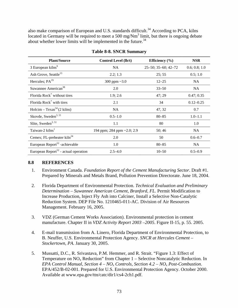
73
also make comparison of European and U.S. standards difficult.34 According to PCA, kilns located in Germany will be required to meet a 500 mg/Nm3 limit, but there is ongoing debate about whether lower limits will be implemented in the future.34
Table 8-8. SNCR Summary
Plant/Source Control Level (lb/t) Efficiency (%) NSR
3 European kilns9 NA 25–50; 35–60; 42–72 0.6; 0.8; 1.0
Ash Grove, Seattle13 2.2; 1.3 25; 55 0.5; 1.0
Hercules; PA19 300 ppm ~3.0 12–25 NA
Suwannee American38 2.0 33–50 NA
Florida Rock7 without tires 1.9; 2.6 47; 29 0.47; 0.35
Florida Rock7 with tires 2.1 34 0.12–0.25
Holcim – Texas54 (2 kilns) NA 47, 32 0.7
Skovde, Sweden3, 51 0.5–1.0 80–85 1.0–1.1
Slite, Sweden3, 51 1.1 80 1.0
Taiwan-2 kilns1 194 ppm; 284 ppm ~2.0; 2.9 50; 46 NA
Cemex; FL-preheater kiln24 2.0 50 0.6–0.7
European Report52 -achievable 1.0 80–85 NA
European Report52 - actual operation 2.5–4.0 10–50 0.5–0.9
8.8 REFERENCES 1. Environment Canada. Foundation Report of the Cement Manufacturing Sector. Draft #1.
Prepared by Minerals and Metals Brand, Pollution Prevention Directorate. June 18, 2004.
2. Florida Department of Environmental Protection. Technical Evaluation and Preliminary Determination – Suwannee American Cement, Branford, FL. Permit Modification to Increase Production, Inject Fly Ash into Calciner, Install a Selective Non-Catalytic Reduction System. DEP File No. 1210465-011-AC. Division of Air Resources Management. February 16, 2005.
3. VDZ (German Cement Works Association). Environmental protection in cement manufacture. Chapter II in VDZ Activity Report 2003 –2005. Figure II-15, p. 55. 2005.
4. E-mail transmission from A. Linero, Florida Department of Environmental Protection, to B. Neuffer, U.S. Environmental Protection Agency. SNCR at Hercules Cement – Stockertown, PA. January 30, 2005.
5. Mussatti, D.C., R. Srivastava, P.M. Hemmer, and R. Strait. “Figure 1.3: Effect of Temperature on NOx Reduction” from Chapter 1 – Selective Noncatalytic Reduction. In EPA Control Manual, Section 4 – NOx Controls, Section 4.2 – NOx Post-Combustion. EPA/452/B-02-001. Prepared for U.S. Environmental Protection Agency. October 2000. Available at www.epa.gov/ttn/catc/dir1/cs4-2ch1.pdf.

74
6. U.S. Environmental Protection Agency. NOx Control Technologies for the Cement Industry. Prepared by EC/R Incorporated. September 19, 2000. Available at www.epa.gov/ttn/naaqs/ozone/ozonetech/cement_nox_update_09152000.pdf.
7. Linero, A. SNCR NOx at US Cement Plants. Is SCR Close Behind? Paper #638 presented at the AWMA Annual Conference. June 2005.
8. Florida Department of Environmental Protection. Technical Evaluation & Preliminary Determination. Suwannee American Cement. Proposed Kiln Line No. 2, Branford, FL. November 8, 2005.
9. Schafer, S. Staged Combustion and SNCR Technology – an Emerging Technique? Research Institute of the Cement Industry (Duesseldorf). Seminar S04-05. Bernburg. European Cement Research Academy. November 3–4, 2004.
10. Mussatti, D.C., R. Srivastava, P.M. Hemmer, and R. Strait. “Section 1.2.3 SNCR Performance Parameters” from Chapter 1 – Selective Noncatalytic Reduction. In EPA Control Manual, Section 4 – NOx Controls, Section 4.2 – NOx Post-Combustion. EPA/452/B-02-001. Prepared for U.S. Environmental Protection Agency. October 2000. Available at www.epa.gov/ttn/catc/dir1/cs4-2ch1.pdf.
11. Hower, J. Cement Kiln Application of Selective Non-Catalytic Reduction – Myth or Reality? Presented at IEEE Florida Meeting, May 2002
12. Mussatti, D.C., R. Srivastava, P.M. Hemmer, and R. Strait. “Figure 1.5: Effect of Uncontrolled NOx Level on NOx Reduction Efficiency” from Chapter 1 – Selective Noncatalytic Reduction. In EPA Control Manual, Section 4 – NOx Controls, Section 4.2 – NOx Post-Combustion. EPA/452/B-02-001. Prepared for U.S. Environmental Protection Agency. October 2000. Available at www.epa.gov/ttn/catc/dir1/cs4-2ch1.pdf.
13. Steuch, H.E., J. Hille, W.H. Sun, M.J. Bisnett, and D.W. Kirk. “Reduction of NOx Emissions from a Dry Process Preheater Kiln with Calciner Through the Use of the Urea Based SNCR Process.” IEEE Transactions on Industry Applications, Vol. 32, Issue 4, July/August 1996. Pp. 753–759.
14. U.S. Environmental Protection Agency. Alternative Control Techniques Document – NOx Emissions from Cement Manufacturing. EPA-453/R-94-004. March 1994. Available at www.epa.gov/ttn/cata/dir1/cement.pdf.
15. Letter from H. Knopfel, Process and Environmental Manager, Lafarge Cement, Davenport, IA, to C.A. Roling, Environmental Engineer, Iowa Department of Natural Resources. Project #96-494 (SNCR Technology). May 14, 1998.
16. Lehigh Portland Cement Company. Selective Non-Catalytic NOx Reduction Demonstration (SNCR). Mason City, Iowa, Plant. December 22, 2000.
17. Lanier, W.S. Public Comment to Proposed PSD Permit for Lafarge Davenport Cement Manufacturing Facility. Energy and Environmental Research Corporation. Undated

75
18. Williams, K.E. Hercules Cement Company & the Use of Ammonium Hydroxide Solution to lower NOx Emissions at its Stockertown, PA Plant. Presented at the AWMA Annual Meeting, San Diego, CA. June 22–26, 2003.
19. E-mail transmission from W. Nuver, Air Quality Program, Pennsylvania Department of Environmental Protection, to B. Neuffer, U.S. Environmental Protection Agency. Hercules Cement SNCR. March 9, 2005.
20. E-mail transmission from A. Linero, Florida Department of Environmental Protection, to B. Neuffer, U.S. Environmental Protection Agency. SNCR at Hercules Cement – Stockertown, PA. January 30, 2005.
21. E-mail transmission from D. Thorley, Michigan Department of Environmental Protection, to B. Neuffer, U.S. Environmental Protection Agency. SNCR system at St Mary’s Cement – Charlevoix, Michigan. June 2, 2005.
22. E-mail transmission from D. Thorley, Michigan Department of Environmental Protection, to B. Neuffer, U.S. Environmental Protection Agency. Charlevoix 2005 NOx numbers MDEQ.xls. October 25, 2005.
23. Teleconference. C. Dennison, St Mary’s Cement, with B. Neuffer, U.S. Environmental Protection Agency. SNCR Test Trails – St Marys Cement. October 25, 2005.
24. E-mail transmission from A. Linero, Florida Department of Environmental Protection, to B. Neuffer, U.S. Environmental Protection Agency. SNCR on Preheater Kiln. October 26, 2005.
25. Letter from A. Linero, Florida Department of Environmental Protection, to B. Neuffer, U.S. Environmental Protection Agency. Comments on Draft Alternative Control Techniques Document Update – NOx Emissions from New Cement Kilns (June 2006). July 18, 2007.
26. E-mail transmission from I. Uphoff, Downwinders at Risk, Dallas, TX, to B. Neuffer, U.S. Environmental Protection Agency. Summary of 11/30/05 call. December 1, 2005.
27. E-mail transmission from I. Uphoff, Downwinders at Risk, Dallas, TX, to B. Neuffer, U.S. Environmental Protection Agency. Holcim – Midlothian. December 7, 2005.
28. E-mail transmission from I. Uphoff, Downwinders at Risk, Dallas, TX, to B. Neuffer, U.S. Environmental Protection Agency. Holcim – Midlothian. December 8, 2005.
29. Letter from M. Moser, Plant Manager, Holcim, Midlothian, TX, to R. Hamilton, Texas Commission on Environmental Quality. Holcim (Texas) LP – Submittal of Selective Non-Catalytic Reduction (SNCR) Pilot Test Summary Report. November 29, 2005.
30. Letter from A. Armendariz to M. Moser, Plant Manager, Holcim, Midlothian, TX. December 28, 2005.
76
31. Teleconference. M. Moser, Holcim, with B. Neuffer, U.S. Environmental Protection Agency. May 31, 2006.
32. Missouri Department of Natural Resources. Project Review of Application for Permit to Construct According to 10 CSR 10-6.060 Section (8). Holcim US – Lee Island Project, Bloomsdale, MO. Undated.
33. Missouri Department of Natural Resources. Permit to Construct, Permit Number 062004-005. Holcim – Lee Island Project, Bloomsdale, MO. June 8, 2004.
34. E-mail transmission from T. Carter, Portland Cement Association, to B. Neuffer, U.S. Environmental Protection Agency. PCA Comments on the Comments submitted by Mr. A. A. Linero on July 18, 2007, on the Draft Alternative Control Techniques document Update – NOx Emissions from New Cement Kilns. Draft dated June 2007. September 6, 2007.
35. E-mail transmission from C. Roling; Iowa Department of Natural Resources, to B. Neuffer, U.S. Environmental Protection Agency. Summary of telecom on Lehigh PC – Mason City, IA. January 26, 2005.
36. Arizona Department of Environmental Quality. Class I Prevention of Significant Deterioration Operating Permit Application – ADEQ Permit No. 1001770. Drake Cement, L.L.C., Phoenix, AZ. January 4, 2005.
37. Letter from R.R. Patron, Drake Cement, Phoenix, AZ, to E. Massey; Air Quality Permits Section, Arizona Department of Environmental Quality. Air Quality Permit Application No. 1001770 – Five Technical Issues. February 25, 2005.
38. Polysius Corporation. Selective Non Catalytic Reduction Test Report. Suwannee American Cement, Branford, FL. November 2004.
39. Letter from J. Horton, Suwannee American Cement, to T. Vielhauer, Florida Department of Environmental Protection. Selective Non-Catalytic Reduction (SNCR) Test Report. February 10, 2005.
40. E-mail transmission from A. Linero, Florida Department of Environmental Protection, to B. Neuffer, U.S. Environmental Protection Agency. SNCR Start ups in Suwannee. March 23, 2005.
41. E-mail transmission from A. Linero, Florida Department of Environmental Protection, to B. Neuffer, U.S. Environmental Protection Agency. More cement news from Florida. May 23, 2005.
42. Letter from M.G. Cooke, Director, Division of Air Resource Management, Florida Department of Environmental Protection, to T. Messer, Plant Manager, Suwannee American Cement, Branford, FL. Production Increase, Fly Ash Injection, SNCR. March 7, 2005.
77
43. E-mail transmission from T. Carter, Portland Cement Association, to B. Neuffer, U.S. Environmental Protection Agency. PCA Comments on the Alternative Control Techniques Document Update – NOx Emissions from New Cement Kilns Draft dated June 2007. August 20, 2007.
44. E-mail transmission from A. Linero, Florida Department of Environmental Protection, to B. Neuffer, U.S. Environmental Protection Agency. Latest Cement News. Available at www.dep.state.fl.us/Air/permitting/construction/flrock.htm. March 30, 2005.
45. Florida Department of Environmental Protection. Best Available Control Technology Determination (BACT) – Florida Crushed Stone, Brooksville, FL. Available at www.dep.state.fl.us/Air/permitting/construction.htm. Accessed March 6, 2007.
46. Florida Department of Environmental Protection. Technical Evaluation, Preliminary Determination, Draft BACT Determinations – American Cement Company, Sumterville, FL. December 16, 2005. Available at www.dep.state.fl.us/Air/permitting/construction/ americanTEPD361.pdf.
47. Terry, M.S. From BACT: What is Achievable with Today’s Technologies? Polysius Corporation. Undated
48. E-mail transmission from M. Roberts, Maine Department of Environmental Protection, to B. Neuffer, U.S. Environmental Protection Agency. Dragon Cement – Thomaston, ME. March 9, 2007.
49. E-mail transmission from M. Roberts, Maine Department of Environmental Protection, to B. Neuffer, U.S. Environmental Protection Agency. Dragon Cement – Thomaston, ME. March 13, 2007.
50. E-mail transmission from B. Neuffer, U.S. Environmental Protection Agency, to M. Roberts, Maine Department of Environmental Protection. Dragon Cement – Thomaston, ME. March 9, 2007.
51. VDZ (German Cement Works Association). Environmental protection in cement manufacture. Chapter II in VDZ Activity Report 2003 –2005. Figure II-15, p. 55. 2005.
52. Swedish Environmental Protection Agency. Reduction of nitrogen oxides with SNCR technology at Slite cement plant. Per Junker, Director of Environment Protection. Session 16 Cement Industry.
53. Scur, P., and H. Hoppe. The present state of NOx abatement with the SNCR process. Cement International. February 2006.
54. Holcim. SNCR Pilot Test Report. Midlothian Plant. November 2005.

78
[This page intentionally left blank.]
79
9.0 MULTISTAGE COMBUSTION (MSC) AND SELECTIVE NONCATALYTIC REDUCTION (SNCR)
Most if not all new PH/PC kiln systems will have some form of MSC. This section summarizes studies on the effect of the combination of MSC and SNCR. In an MSC calciner, part of the calciner fuel is introduced at the kiln inlet to reduce the NO generated in the kiln. The adjustable division of the tertiary air allows part of the calciner to be operated under sub-stoichiometric conditions. This leads to the reduction of NO formation from the fuel nitrogen and, depending on the type of calciner fuel used, the reduction of more of the NO produced in the kiln.
One European report1 states that considerable CO is formed in staged combustion, but that most of the CO is burned out in the area of the mixing chamber and the bottom cyclone stage. Operation of an SNCR system substantially impairs CO burn-out. During SNCR trials, CO rose from 0.02 to 0.05%.2
Causes for the interaction between the SNCR and CO burn-out rate have not been identified. SNCR and CO decomposition both require OH radicals. It may be preferable to create separate reaction zones for SNCR and MSC. If SNCR is installed in an existing calciner kiln, this can be implemented by injecting the reducing agent at a point where co-burning has progressed sufficiently. The design of new calciners should allow for sufficient gas residence time to allow CO burnout and SNCR reactions to take place consecutively.
A European study was undertaken to study the combination of SNCR and staged combustion as an “emerging technique.” It was assumed that this combination could attain NOx emissions of 100–200 mg/m3.2
The report states that there are competitive reactions of MSC and SNCR. These reactions are listed below.
NOx reduction NH3 + OH NH2 + H2O NH2 + NO N2 + H2O CO oxidation CO + OH CO2 + H
Four different kilns were tested to evaluate the effects of SNCR on PH/PC kilns with staged combustion; the results of these tests are summarized below. As shown in Table 9-1, NOx reductions attributable to only SNCR varied from 45–65%. CO emissions increased when the NSR was at least 1.2, and the NOx reduction due to SNCR was at least 50%.

80
Table 9-1. Effect of SNCR on Emissions with Staged Combustion2
Kiln B B D M X X
NSR 0.6 0.9 1.2 1.5 2.5 2.7
NOx reduction due to SNCR (percent)
47 45 50 65 65 65
CO increase (ng/ m3) 0 0 125 375 290 950
Figure 9-1 illustrates the effects on NO levels resulting from the injection of ammonia in the burnout zone. As NSR increases (more NH3 injected), the level of NOx emitted decreases. These effects are also summarized in Table 9-2.
Injection of reducing agent in burnout zoneInfluence of NH3/NOx molar ratio
0
1
2
3
4
0
meal frompreheater
fuel
fuel(kiln inlet)
tertiary air
2.01.51.00.5 2.5 3.0 3.5
without SNCR
Reduktionsmittel-Zugabeinput of reducing agent in burnout zone
NO massflow in kg NO/t clinkerG
as re
side
nce
time
in s
symbol
00.51.11.42.2
NH3/NO molar ratiolowestcyclonestage
after mixing chamber
Figure 9-1. NH3 injection – burnout zone.2
Table 9-2. Impact of Injecting Ammonia in Burnout Zone2
NSR NO After Mixing Chamber NO in Lowest Cyclone Stage NO
kg/mt lb/t kg/mt lb/t
0 1.8 3.6 1.8 3.6
0.5 1.6 3.2 1.6 3.2
1.1 1.3 2.6 1.3 2.6
1.4 1.1 2.2 1.1 2.2
2.2 0.4 0.8 0.3 0.6

81
The impacts of injecting ammonia in the reducing zone are illustrated in Figure 9-2 and summarized in Table 9-3. These show that the level of NOx emissions consistently decreases with increasing NSR.
Injection of reducing agent in reducing zoneInfluence of NH3/NOx molar ratio
0
1
2
3
4
0
meal frompreheater
fuel
fuel (kiln inlet)
tertiary air
2.01.0 3.0
without SNCR
input of reducing agentin reducing zone
NO massflow in kg NO/t clinker
Gas
resi
denc
e tim
e in
s
symbol
00.71.42.02.7
NH3/NO molar ratio lowestcyclonestage
after mixing chamber
Figure 9-2. NH3 injection – reducing zone.2
Table 9-3. Impact of Injecting Ammonia in Reducing Zone2
NSR NO After Mixing Chamber NO in Lowest Cyclone Stage
kg/mt lb/t kg/mt lb/t
0 1.8 3.6 1.7 3.4
0.7 1.6 3.2 1.6 3.2
1.4 1.2 2.4 1.5 3.0
2.0 0.8 1.6 0.8 1.6
2.7 0.6 1.2 0.7 1.4
The following conclusions regarding the combination MSC and SNCR have been reported: 2
MSC combined with SNCR is feasible CO burnout and SNCR processes affect each other CO can increase The optimum point for feeding the reducing agent should be determined for each
plant.

82
The same report2 had the following conclusions on the interaction of SC with SNCR:
The higher the ammonia input into the combustion chamber, the more retarded the CO burnout
CO can increase if the residence time is too short after injection The calciner design must provide 1–1.5 seconds residence time for SNCR The input of the reducing agent can be limited by the potential for CO increase. CO
increase can be avoided by increasing the air ratio in the reduction zone (less air staging).
The report stated that the solution to increased CO levels is to improve burnout by
increasing the air ratio in the reduction zone (less air staging).
According to the Florida DEP, a cement kiln in Florida would operate very comfortably at around 3.6 to 4 lb/t of clinker in a PH/PC kiln with oxidizing conditions in the calciner.3 Efforts toward MSC and a high-temperature reducing atmosphere will result in costs due to increased coatings, pluggage, and the increased sizes of precalciner and preheater. An emission rate between 1 and 4 lb/t of clinker is BACT for the given kiln. There will be a least-cost combination of SCC and SNCR or just one or the other. According to the Florida DEP, BACT will be much closer to the lower end of the range of emissions.3
Krupps-Polysius conducted trials indicating that the combination of MSC with SNCR can achieve values of 800 mg for existing kilns and 500 mg/Nm3 for new kilns.4 The MSC calciner is characterized by kiln inlet burner, staggered tertiary air introduction, staggered meal introduction, and a deflection chamber located before the first cyclone. Best results for NOx reduction were obtained by injecting an ammonia solution before and after the deflection chamber. The smallest plants show the best reduction rates. This is attributable to the difficulty of mixing a small amount of liquid into a large gas volume. A reduction occurs only above a molar ratio of 0.2; below this, it cannot be ruled out that part of the ammonia oxidizes and reduces the reduction effect to such an extent that it is practically zero.
A CO increase is also linked to the molar ratio. With molar ratios of less than 1, CO increases range between 150–350 mg/m3. Above molar ratios of 1, CO increases can reach 600–800 mg/m3, depending on the magnitude of the molar ratio. This CO increase is not a characteristic of the combined MSC/SNCR process, but is instead due to the SNCR process itself.
The use of MSC/SNCR controls becomes economically attractive at total reduction rates above 35–45%. MSC leads to a reduction in ammonia requirements for SNCR. SNCR allows kiln operation without direct coupling to emission limits, leaving the kiln operator more freedom of action.
9.1 REFERENCES
1. VDZ (German Cement Works Association). Environmental protection in cement manufacture. Chapter II in VDZ Activity Report 2003–2005. Figure II-15, p. 55. 2005.
83
2. Schafer, S. Staged Combustion and SNCR Technology – an Emerging Technique? Research Institute of the Cement Industry (Duesseldorf). Seminar S04-05. Bernburg. European Cement Research Academy. November 3–4, 2004.
3. E-mail transmission from A. Linero, Florida Department of Environmental Protection, to B. Neuffer, U.S. Environmental Protection Agency. RE: Cement Kilns – SNCR. January 6, 2005.
4. Erpelding, R. NOx Reduction with the MSC/SNCR combination: Chances and Risks. Krupp Polysius AG. Undated.

84
[This page intentionally left blank.]
85
10.0 SELECTIVE CATALYTIC REDUCTION (SCR)
On a worldwide basis, three cement kilns have used SCR: Solnhofen Zementwerkes in Germany and Cementeria di Monselice and Italcementi Sarche di Calavino in Italy. The SCR system was operated at the Solnhofen plant from 2001 to January 2006, at which time the plant began using SNCR to compare the operational costs of the two systems to evaluate which technology is better and more economical. As of this date, it is not clear if the plant will go back to SCR. Both Solnhofen and Cementeria di Monselice have preheater kilns. The Italcementi plant operates a small Polysius Lepol technology kiln. These plants will be discussed in detail later in this section.
10.1 PROCESS DESCRIPTION
SCR is the process of using ammonia or urea in the presence of a catalyst to selectively reduce NOx emissions from exhaust gases. The SCR process has been used extensively on gas turbines, internal combustion (IC) engines, and fossil fuel-fired utility boilers. In the SCR system, anhydrous ammonia, usually diluted with air or steam or aqueous ammonia solution, is injected through a catalyst bed to reduce NOx emissions. A number of catalyst materials have been used, such as titanium dioxide, vanadium pentoxide, and zeolite-based materials. The catalyst is typically supported on ceramic materials (e.g., alumina in a honeycomb monolith form) and promotes the NOx reduction reactions by providing a site for these reactions to occur. The catalyst is not consumed in the process but allows the reactions to occur at a lower temperature.
The optimum temperature for the catalyst reactions depends on the specific catalyst used. Several different catalysts are available for use at different exhaust gas temperatures. Base metal catalysts are useful between 450 °F and 800 °F (232 °C and 427 °C). For high temperature operations (675 °F [357 °C] to over 1100 °F [593 °C]), zeolite catalysts containing precious metals such as platinum and palladium are useful. The two principal reactions in the SCR process at cement plants using SCR are the following:
4 NH3+ 4 NO + O2 4 N2 + 6 H2O (predominant reaction as most NOx is NO) 4 NH3 + 2 NO2 + O2 3 N2 + 6 H2O
It is important to note that the desired chemical reactions are identical with SNCR and SCR. The only difference is that with SCR, a catalyst is present, which allows the reactions to occur at a lower temperature.1
In an SCR system, ammonia is typically injected to produce a NH3: NOx molar ratio of 1.05–1.1:1 to achieve a NOx conversion of 80–90% with an ammonia slip of about 10 ppm of unreacted ammonia in gases leaving the reactor.2 The NOx removal efficiency depends on the flue gas temperature, the molar ratio of ammonia to NOx, and the flue gas residence time in the catalyst bed. All these factors must be considered in designing the desired NOx reduction, the appropriate reagent ratios, the catalyst bed volume, and the operating conditions. As with SNCR, the appropriate temperature window must be maintained to assure that ammonia slip does not result in a visible plume.2, 3

86
SCR can be installed at a cement kiln at two possible locations:
After the PM control device – a “low-dust” system. After the last cyclone without ducting – a “high-dust” system.
The advantages of a “low-dust” system are longer catalyst life and lower danger of blockage. The disadvantage is the additional energy costs required to heat the cooled exhaust to achieve proper reaction temperatures in the catalyst.
The advantage of a high-dust system is that the exhaust gas temperature after the cyclone is more or less equal to the temperature required by the catalyst. Additional heating is not required.3 The two European cement kilns controlled by SCR are high-dust applications.
The catalysts may be fouled or deactivated by the PM in the flue gas, and soot blowers have been used to help alleviate this problem. Also, the presence of alkalis and CaO and SO2 in exhaust gas is of concern. For coal-fired boilers, SCR is typically installed after PM control. In a cement kiln application where the SCR is placed after the PM control, flue gas reheating would be required because the temperature of the kiln exhaust after PM control is lower than typical SCR operating temperatures.
10.2 EQUIPMENT NEEDED FOR SCR4
The main component of SCR is the catalyst. The SCR catalyst composition and shape will vary depending on the application. Commonly, a carrier titanium oxide and active vanadium oxide components are supported on a ceramic substrate. Each catalyst module may be in a honeycomb or plate configuration and is typically arranged in a series of layers called beds. A support structure is required to house the catalyst beds and hold them in place. The enclosed chamber where the gases and ammonia react on the catalyst is called the SCR reactor.
Dust loading can lower the overall effectiveness of the catalyst. In a high-dust environment, the catalyst may actually become plugged. As a catalyst becomes plugged, the pressure drop across the catalyst increases; therefore, a catalyst-cleaning system must accompany the catalyst. Cleaning systems may include equipment such as dampers to reverse the gas flow, or additional devices such as sonic horns to vibrate dust loose. These systems may also use pressurized air nozzles or blowers to blow the dust from the catalyst. Pressurized air used to clean the catalyst must be preheated to maintain the temperature around the catalyst in the range that is optimal for the ammonia-NOx reaction to take place, approximately 300–450 °C (570–840 °F) and to avoid localized acid gas dew point problems.
These cleaning techniques can be used while the SCR system operates. It is sometimes necessary to periodically remove each individual catalyst bed for more thorough cleaning using water or other solvent solutions. The system may include hoists, trolleys, or a crane to remove the catalyst beds. The wastewater and solids generated during this cleaning process must be properly managed and disposed.
As exhaust gases move past or through the catalyst, there will be an additional pressure drop. To move the gases, existing air-handling equipment, such as fans and blowers, may need to be scaled up. Eventually, a catalyst will reach the end of its useful life and need to be replaced

87
with new catalyst elements. If not physically damaged, a catalyst can often be regenerated and used again. Figure 10-1 shows the tower structure that holds the catalyst, SCR reactor, and gas –moving and connection ductwork at the Solnhofen plant. As shown here, the SCR reactor and the associated ductwork is substantial in both size and required foundations for support.
Figure 10-1. SCR system adjacent to preheater tower at Solnhofen
Portland cement plant.5
As with SNCR, SCR requires onsite vessels and a truck-unloading stand to receive and store ammonia or urea. Ammonia and urea may be received as a liquid solution or may be mixed onsite with water to the desired solution concentration. If mixed on site, additional water storage, purification, pumping, and mixing equipment is required.
The ammonia solution is pumped through metal pipes and delivered into the reaction chamber through a reaction lance. This will require a pump, pump skid, and ammonia control unit. The exact location and number of injection points will differ from one system to the next and is optimized through testing. Measurement equipment is necessary to maintain the correct feed rate of ammonia. Additional monitoring equipment is required to record the amount of NOx and ammonia slip from the gases exiting the system to adjust the amount of ammonia entering the system.
Temperature and pressure readings from inside the SCR reactor are required for proper system adjustment and control. Finally, a bypass duct system is required in case the pressure drop through the SCR becomes too large, the temperatures become too high or too low for proper catalyst performance, or the SCR reactor needs to be taken offline for catalyst change-out.
10.3 EARLY PILOT TESTS
10.3.1 USA
In 1976, Hitachi Zosen, an SCR manufacturer, conducted three test programs on two suspension preheater kilns and a wet process kiln.6 Each kiln was tested for 5,400 hours. ESPs

88
were used to remove PM before the flue gas entered the SCR unit. Also, a heat-recovery system with supplemental fuel firing was used to raise the flue gas temperature to the required reaction temperature. Slipstreams of about 3,000 standard cubic feet per minute (scfm) were treated with initial NOx removal efficiencies of 98%; however after about 5,400 hours of operation, NOx removal efficiencies dropped to about 75% due to catalyst coating.6 Based on these tests, the ACT stated that SCR is a possible technology for cement kilns. The NOx reductions were projected to be 80–90% regardless of kiln type.6 Further developmental studies are needed to demonstrate the specific NOx reduction.6
10.3.2 Europe
ELEX is a Swiss engineering firm that has tested SCR at three different pilot units at three different cement plants for a total of 30,000 operating hours.7 The first pilot test was in Italy in 1996; however, information about this unit is not readily available. The second pilot test was conducted in Kirchdorf, Austria, using a slipstream of 3,500 m3/hr. The pilot plant was operated starting in 1996 for about 13,000 hours or about 2 years. NOx was reduced continuously to 200 mg/Nm3 (one-half hour average). Ammonia slip was under 5 mg/Nm3.
Liquid ammonia was the reagent used, and the SCR unit had three catalyst layers. The catalyst was placed ahead of the PM control. The gas temperature was between 300–400 °C (570–750 °F) with a dust load of 80 g/m3. SO2 concentrations were typically between 150–300 mg/Nm3.
Some inlet concentrations of 640 mg/Nm3 (~ 2.6 lb/t) were reduced to 100 mg/Nm3
(~0.4 lb/t) and below. Ammonia slip was considerably below 5 mg/Nm3. After 2,200 operating hours, the catalyst activity was 92%. The pilot was operated for 13,000 hours with low NOx emissions, low ammonia slip, and no unexpected drop in catalyst activity.
The third pilot test was at Slite Cement in Sweden. Although the test was successful, the plant was able to achieve low NOx emissions using SNCR, so a full-scale SCR system was not constructed.
10.4 SCR INSTALLATIONS
10.4.1 Solnhofen – Germany 3, 4, 8, 9, 11
As mentioned above, there are three known cement kilns in the world that have used SCR. The first plant that installed SCR is Solnhofer Zementwerkes in Solnhofen, Germany. The Solnhofen cement kiln is a preheater kiln, not a PH/PC kiln system. As discussed earlier, uncontrolled NOx emissions for preheater kilns are higher than PH/PC kilns. The Solnhofen plant produces 500,000 mt/yr (555,000 t/yr) of cement.
A pilot-scale demonstration was conducted in 1997–99 at Solnhofen. The SCR system was installed after the preheater in temperature between 300–340 °C (570–640 °F). The pilot demonstration showed the following:
Catalyst pitch should be greater than 8 mm for easier cleaning

89
NOx was reduced by 30% with no ammonia usage other than the ammonia in the raw materials
NOx reduction rates above 90% were achieved with ammonia slip less than 5 ppm.
A commercial SCR was installed at Solnhofen in 2000 (see Figure 10-1). The SCR installation was a high-dust installation (i.e., the SCR reactor is located before the PM control device) and uses a 25% aqueous ammonia solution. The system reduced raw material NH3 that might have otherwise been converted to raw material NOx. Also, ammonia slip was less than 1 mg/m3. Reductions of hydrocarbons and SO2 in the order of 50–70% were also attained.
The reactor can be equipped with six catalyst layers, of which three layers are used. Using these three layers, 200 mg/Nm3 (~ 0.8 lb/t) of NOx is achieved from an inlet of 1,050 mg/Nm3 (4.2 lb/t) or 80% control. The ammonia slip is less than 1 mg/m3. In January 2006, the catalyst had logged approximately 40,000 hours and was in need of replacement.1 The catalyst was guaranteed for 16,000 hrs, with an expected catalyst life of 3–4 yrs.
NOx standards are 1000 mg/Nm3 on a half-hour basis and 500 mg/Nm3 on daily basis.(~ 4.6 and 2.3 lb/t, respectively). In 2004, the facility complied with the 500mg/Nm3 limit 72.3% of the time and, in 2005, 90.8% of the time.1 During pilot testing and short-term testing of the full-scale system, the facility achieved levels as low as 200 mg/Nm3 (0.8 lb/t).1
The gas temperature inlet to the SCR unit is 320–340 °C (610–640 °F).3, 9
The NOx removal efficiency is typically in the range of 59–67%. Under operating conditions of 3,000 mg/Nm3 and higher, NOx removals of more than 80% have been observed. In normal operation, At NOx levels of 1,000–1,600 mg/Nm3,SCR reduces NOx to about 400–550 mg/Nm3. It is to be noted that the plant was designed to comply with a NOx emission limit of 500 mg/Nm3 and that it typically was able to meet this level. With a molar ratio of 0.8–0.9, ammonia consumption is significantly lower than SNCR. It is also noted that NH3 from the raw material also serves as reducing agent in the reactor. Thus, the emission level of residual ammonia is very low. Using SCR at Solnhofen, NH3 emissions are usually below 1 mg/Nm3.10
The plant has continuous emission monitors (CEMs) for chlorides, PM, SO2, NOx and Hg. The kiln also has an SO2 standard of 0.23 lb/t on daily basis. This value is met 100% of the time. Also, the catalyst efficiently utilizes ammonia (including ammonia in the raw material), so it is not available for detached plume formation.11
Some of the stone used for raw material contains natural sources of ammonia. The raw materials are also naturally low in both sulfur and alkali. Due to the low alkali, there is no alkali bypass. Since there is no alkali in the process to balance sulfur or chlorine, the facility must limit sulfur and chlorine in the raw materials or fuels to limit the buildup of deposits in the preheater tower. Due to the lack of sulfur in the raw materials and the self-imposed low-sulfur limit on the fuels, the emissions of SO2 are nearly at the detection limit of the monitor.1
The facility achieves NOx reductions by using a combination of a low NOx burner, alternative/waste fuels and either SNCR or SCR. The SNCR and SCR systems do not operate simultaneously. The LNB and alternative/waste fuels reduced NOx by 40% (from baseline of 1,500–1,800 mg/Nm3 to 800–1,200 mg/Nm3). Using SNCR or SCR further reduces NOx by
90
approximately 50%. The facility achieves the current NOx emission limit of 500 mg/Nm3 (a 70% reduction from uncontrolled baseline). This limit is a 24-hour average and was issued in 2002 when the facility operating permit was issued. The SCR construction permit has a goal of 200 mg/Nm3; however, the facility has not achieved this level.4
The slipstream pilot test unit tested various plate catalyst. The dust loading in the preheater gas (80–100 g/Nm3), and pressurized cleaning eroded the catalyst from the metal substrate. Within 1,000 hours, the reactivity of catalyst was not acceptable. When the full-scale SCR system was constructed, a honeycomb catalyst was installed. At the time of SCR full-scale installation, an 8-mm catalyst pitch was the largest opening commercially available.1 In this high-dust operation, the catalyst plugged within minutes of commencing SCR operation. Eventually, the facility completed the custom manufacturing and testing of honeycomb catalysts with larger pitch and with various catalyst formulations. The catalyst configuration that has shown the best results is as follows: the first SCR layer contains honeycomb catalyst with a 13 mm pitch. The third and fifth layers contain honeycomb catalysts with 10 mm pitch. The second, fourth, and sixth layers are empty. The seventh layer contains a heat exchanger, which preheats the air utilized for pressurized cleaning. Each catalyst bed contains six modules. Each of these modules contains 144 catalyst elements in a 12 x 12 arrangement. The total depth of each catalyst layer is 35.4 inches. A bypass duct allows the facility to bypass the SCR system whenever temperature or pressure drop requires a bypass.
The most recent catalyst cleaning system utilizes preheated compressed air that continuously cleans the catalyst. Dry compressed air at about 900 m3/hr at 10 bar pressure passes through a heat exchanger coil located in the seventh stage of the SCR reactor and then passes through insulated lines to each stage/layer of the reactor. Then, the air passes into the reactor, where a series of nozzles are located on two parallel bars that span the width of the reactor. The full cross-sectional area of the catalyst is reached by the cleaning system. Hydraulics are used to move the bars back and forth across the catalyst bed. The speed of the traverse is controlled electronically and can be adjusted when the pressure drop across the reactor begins to rise. The system cycles every 20 minutes and cleans the catalyst in sequence. Roughly every 3,000–4,000 hours, the facility bypasses the SCR to perform additional, more thorough cleaning. This unique cleaning system took 2 to 3 years to conceptualize, construct, and modify to achieve an effective method of catalyst cleaning for this particular cement plant’s design and dust characteristics. According to the equipment vendor KWH Catalyst, Inc., of Germany, the problem of fouling from heavy dust loading has proven to be quite manageable with regular catalyst cleaning.
When operating the SCR system, the facility injects a 25%-by-weight ammonia in water solution, not in the inlet to the system as is typical of power plant applications, but rather to the preheater between the second and third cyclones where the gas temperature is 550 °C (1,020 °F). The facility believes this location allows for the best distribution of ammonia in the flue gas, resulting in the most efficient SCR operation and lowest ammonia slip. If SNCR is used instead of SCR, the ammonia is injected into the preheater, where the gas temperature is approximately 1,000 °C (1,830 °F).
The facility considers the SCR setup reasonably reliable. The plant manger is attempting to find a catalyst manufacturer to produce a plate catalyst with a formulation producing more durability. However, plate catalysts have less surface to volume ratios and less NOx reduction
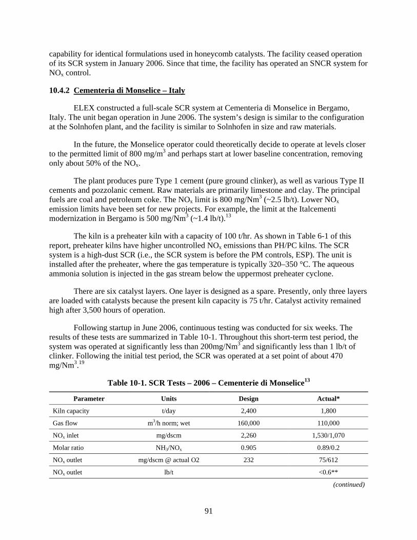
91
capability for identical formulations used in honeycomb catalysts. The facility ceased operation of its SCR system in January 2006. Since that time, the facility has operated an SNCR system for NOx control.
10.4.2 Cementeria di Monselice – Italy
ELEX constructed a full-scale SCR system at Cementeria di Monselice in Bergamo, Italy. The unit began operation in June 2006. The system’s design is similar to the configuration at the Solnhofen plant, and the facility is similar to Solnhofen in size and raw materials.
In the future, the Monselice operator could theoretically decide to operate at levels closer to the permitted limit of 800 mg/m3 and perhaps start at lower baseline concentration, removing only about 50% of the NOx.
The plant produces pure Type 1 cement (pure ground clinker), as well as various Type II cements and pozzolanic cement. Raw materials are primarily limestone and clay. The principal fuels are coal and petroleum coke. The NOx limit is 800 mg/Nm3 (~2.5 lb/t). Lower NOx emission limits have been set for new projects. For example, the limit at the Italcementi modernization in Bergamo is 500 mg/Nm3 (~1.4 lb/t).13
The kiln is a preheater kiln with a capacity of 100 t/hr. As shown in Table 6-1 of this report, preheater kilns have higher uncontrolled NOx emissions than PH/PC kilns. The SCR system is a high-dust SCR (i.e., the SCR system is before the PM controls, ESP). The unit is installed after the preheater, where the gas temperature is typically 320–350 °C. The aqueous ammonia solution is injected in the gas stream below the uppermost preheater cyclone.
There are six catalyst layers. One layer is designed as a spare. Presently, only three layers are loaded with catalysts because the present kiln capacity is 75 t/hr. Catalyst activity remained high after 3,500 hours of operation.
Following startup in June 2006, continuous testing was conducted for six weeks. The results of these tests are summarized in Table 10-1. Throughout this short-term test period, the system was operated at significantly less than 200mg/Nm3 and significantly less than 1 lb/t of clinker. Following the initial test period, the SCR was operated at a set point of about 470 mg/Nm3.19
Table 10-1. SCR Tests – 2006 – Cementerie di Monselice13
Parameter Units Design Actual*
Kiln capacity t/day 2,400 1,800
Gas flow m3/h norm; wet 160,000 110,000
NOx inlet mg/dscm 2,260 1,530/1,070
Molar ratio NH3/NOx 0.905 0.89/0.2
NOx outlet mg/dscm @ actual O2 232 75/612
NOx outlet lb/t <0.6**
(continued)

92
Table 10-1. (continued) Parameter Units Design Actual*
NOx stack Same as above 200 50/408
NOx removal percent 90 95/43
NH3 slip mg/dscm < 5 < 1/< 1
O2 reactor percent 2.5 2.7
O2 stack percent 5.0 7.1/8.8 (compound)
Pressure drop Millibars 15 < 5
NH4OH 25 percent solution; kg/h 445 204/34
* Two separate sets of data were collected for most parameters. ** The system operated at significantly less than 200mg/Nm3.
Fuel burn during the tests was typically 80% petroleum coke blend with various types of coal as backup fuel. After this testing, the set point for NOx is usually at 400 mg/m3. The SCR system is guaranteed by ELEX to reduce NOx by 90% from 2,000 to 200 mg/m3 (uncorrected).12 For testing and demonstrations, NOx is lowered to below 100 mg/m3. Also during these tests, VOC was oxidized by 75%. NH3 emissions before SCR operation were 25–50 mg/ m3 due to ammonia in the raw materials. The ammonia in the raw material is consumed in the SCR process. 13
10.4.3 Italcementi Sarche di Calavino – Italy
An SCR unit was installed at this facility in early 2007. The kiln is a relatively small Polysius LEPOL kiln. Dry meal is conveyed from the blending silos to a nodulizer (a flat pan rotating in an inclined plane) in which the meal is dampened and pelletized before passing into the LEPOL grate. This grate is a long arch-shaped refractory brick-lined structure with a traveling grate where the pellets are partially calcined before they enter the kiln.15
10.5 ISSUES/SOLUTIONS USING SCR AT CEMENT KILNS
Due to the limited experience of using SCR in cement kilns, issues have been raised on the applicability of SCR for cement kilns. The following is a summary of the discussion in the Texas – Ellis County Report15, which explored potential NOx reduction strategies for cement kilns in Ellis County, Texas, and on St. Lawrence Cement (SLC). SLC proposed to construct a new PH/PC kiln at their facility in Greenport, NY. SLC has decided not to construct this kiln. The following summarizes information developed during this process. This information is useful as it presents what some believe are problems with the use of SCR in cement kilns and responses to these apparent problems.
Most SCR systems are designed to operate between 315–390 °C (600–750 °F). For the SLC project, the SCR system would have been located downstream of the preheater cyclones and prior to the roller mill. According to the Mechanical Process Flow Sheet prepared by Krupp, the process exhaust temperature is 320 °C (608 °F) at this location, which is ideal for SCR. Also, it was believed that SCR would not interfere with or affect the cement manufacturing process.16
93
SCR systems have been successfully used at coal-fired power plants for the control of NOx emissions. The Ellis County report notes that due to differences in the nature of cement kiln and coal-fired power plant processes, as well as the chemical composition of the ash and other factors, the successful application of SCR systems to control NOx emissions from cement plants is not certain. Possible problems with SCR use with cement kilns are discussed in the report, such as the high calcium content of cement dust relative to coal dust and the high grain loadings of kiln exhaust gases relative to utility boilers. On the Solnhofen experience with SCR, the report states that it was successful and that issues on SCR use on cement kilns may have been resolved. The report states “SCR is, under certain conditions, a technically feasible alternative for significantly reducing NOx emissions from cement kilns.”14
10.5.1 SO2 Oxidation
In general, operational histories of SCR installations at coal-fired power plants and the one cement plant indicate that NOx reductions are being achieved in a reliable manner. The reason that many of the older units are not achieving NOx removals greater than 80% is that the plants were not designed to achieve higher removal efficiencies. Advances in SCR technology have resulted in present-day SCR systems that typically achieving 90% or greater.14
Detrimental impacts are believed to occur due to significant levels of SO3 in the SCR flue gas due to the oxidation of SO2 by SCR catalyst. The SO3 can cause catalyst pore masking, the formation of ammonium salts that can plug downstream equipment, and acid mist emissions.17
High SO3 concentrations are believed to lead to catalyst deactivation and other serious problems relating to SO2 oxidation. A high SO3 concentration (10–20 ppmv), when coupled with the high calcium level in the cement kiln flue gas, could purportedly cause deactivation of the SCR catalyst due to the masking effect of calcium sulfate. In addition, any SO3 that does not react with the calcium could react with any unused NH3 to form ammonium sulfate or ammonium bisulfate and cause fouling of downstream equipment. Sulfur in the raw meal can be in several forms: calcium sulfate, magnesium sulfate, and sulfites such as pyrites or organically bound sulfur. Only the volatile sulfur compounds (namely the sulfides and organically bound sulfur) are oxidized and released in the preheater as SO2.9
In response to concerns over catalyst deactivation, the use of SCR systems at a number of coal-fired boilers show that SCR systems can be designed for high calcium and high sulfur flue gases. SCR catalyst suppliers have indicated that CaSO4 formation does not pose a major concern because they believe that the SO3 generated in the process is captured by the free CaO in the gas stream. Thus, SO2 oxidation by the catalyst will have no negative impact on the amount of SO3 formed and subsequently captured.
SCR’s success at Solnhofen indicates that the SCR process eliminates 50–70% of SO2. It is unclear where in the process the SO2 removal occurred. The SO2.removal could occur due to adsorption of SO2 in the baghouse that replaced an ESP.16
The conversion of SO2 to SO3 by an SCR is dependent on the raw materials used at each plant and will vary for each plant. The problem is, in part, minimized by the presence of moist
94
limestone dust in the raw mill that will capture SO3. When the raw mill is down, the injection of fine hydrated lime mist can be practiced if needed.10
Also, the catalyst at Solnhofen has completed 24,000 hours of operation without any plugging problems or acid mist emissions. The presence of high SO3 concentration has not led to catalyst deactivation and other problems at facilities with high calcium and high sulfur flue gases based on experience at various coal-fired plants.18
10.5.2 High CaO Loading and Potential Masking – CaSO4 Formation
SO3 oxidation could lead to catalyst masking by CaSO4 formation and the generation of significant levels of sulfuric acid mist. SLC at Greenport will have SO2 concentration of 177 mg/Nm3 (600 ppmv) in the preheater exhaust gas. With 0.5–2.0% SO2 oxidation, a high SO3 concentration of 8–17 ppmv could result. This high SO3 concentration, along with the high calcium level in the cement kiln flue gas, would deactivate SCR catalyst due to masking effects of calcium sulfate.17
However, catalyst plugging problems can be prevented by managing the type and frequency of soot blowing and by using a heated, compressed air blowing system.16
10.5.3 Ammonium Bisulfate14
SO3 that does not react with calcium may react with any ammonia slip from the SCR unit to form ammonium sulfate or ammonium bisulfate, which could cause fouling of downstream equipment. Solnhofen has not had to face SO3 concentrations of this magnitude because inlet SO2 is so low.17 Where raw material SO2 levels are high, formation of ammonium salts may be a problem.
Also, it is argued that ammonium salts could increase condensable PM levels, making it difficult for a facility to meet its PM limits.9
In SCR systems with SO2, NH3, and moisture present, ammonium salts will form at temperatures below 300–310 °C (580–590 °F). The best way to prevent their formation is to continuously control the SCR inlet temperature such that it is always 310 °C (600 °F) or greater. Regarding the possible release of SO3, catalyst manufacturers report that SO3 gas is totally captured by conversion to particulate calcium sulfates and sulfites because it is contacted by free lime upstream, within, and downstream of the SCR catalyst. Thus, the formation of undesirable byproducts should be inherently controlled by the free CaO in the system and can be further controlled by controlling the SCR inlet temperature.14, 16
10.5.4 Water Soluble Alkali – Alkali Poisoning – Catalyst Deactivation9, 14, 17
The total quantity of poisons and availability of catalyst poisons reaching the vanadium pentoxide in the SCR catalyst needs to be examined.17 There is limited experience with alkali poisoning of catalysts in cement plants to know the extent to which this will be a problem.
Poisoning occurs when contaminants in the gas being treated react with the catalyst, resulting in catalyst deactivation. It’s been argued that SCR in a cement plant will be subject to

95
poisoning, principally from sodium, potassium, and arsenic trioxide. Phosphorous, chromium, and lead compounds can also poison an SCR catalyst, but these are expected to be present in lower concentrations at cement kilns. However, the typical concentration of sodium oxide in the PM of certain coal-fired utilities is greater than double the Na2O concentrations in the PM of the average cement plant. Also, the maximum Na2O concentration in the PM emissions from coal-fired utility boilers can be significantly greater than the maximum expected concentration of Na2O in the average cement plant emissions. Similarly As2O3 concentration of flue gas of typical coal-fired plant is well above the typical concentration expected from the average cement plant.9, 15
10.5.5 Catalytic Deactivation Due to Catalyst Poisoning 13, 14, 16–18
Poisoning occurs when the contaminants in the flue gas react with the catalyst, resulting in catalyst deactivation. In PH/PC kilns, materials such as sodium and potassium compounds may be present in relatively elevated concentrations on particle surfaces in “water soluble” form that can contact the SCR surface of the catalyst bed and poison the V2O5 “active ingredient.” It is argued that in coal-fired boilers, the sodium and potassium are, to a major extent, trapped within a glass-like fly ash particle. Phosphorous, chromium, and lead compounds can also poison an SCR catalyst, but since these are expected to be present in lower concentrations at cement kilns, they are of lesser concern.14 It is widely known, however, that fly ash particles from coal-fired boilers are in the form of tiny spheres and, during combustion, the particles are actually liquid and spheres formed as tiny bubbles by evolved gases trying to escape. Boilers are designed to cool the molten particles to a solid state so that they can be easily removed from boiler tubes. However, depending on the fly ash temperature and its chemical composition, some fly ash will deposit in various sections of the boiler. The deposits that form at the back end of the boiler (on the economizer and air heater) are called “low-temperature deposits.” Low-temperature deposits are usually characterized by low pH; many contain hydrated salts and, for most bituminous coals, are water soluble. Therefore, coal-fired boilers do have fly ash deposits in the economizer section of the boiler that are water soluble; however, deactivation has not been found to occur. Also, SCR systems have been installed on oil-fired boilers despite the relatively higher levels of water- soluble alkaline metals found in the fly ash from such boilers.14, 16
10.5.6 Catalyst Plugging and Fouling Due to High Dust Loading and Depositing of “Sticky Materials”
Catalyst plugging and fouling involves the accumulation of dust that blocks access to the catalyst pores. It is argued that high dust loadings could plug or foul the SCR catalyst beds. However, the Solnhofen SCR system has operated at a dust loading of 80g/Nm3, a relatively high dust loading. The level of NOx removal shows that high dust loading can be managed to avoid catalyst plugging and fouling while maintaining high levels of control. Related to the plugging and fouling issues, it is argued that “sticky deposits” in the preheater exhaust gas could foul and plug the SCR catalyst. Specifically, certain cement kiln operations could be prone to producing sticky deposits at exactly the temperature ranges in which SCR systems operate. Sticky deposits are a widespread problem, occurring on cement kiln induced draft fans. 14
The presence of alkali in cement kilns is a factor in the build up of sticky deposits, i.e., extremely hard, layered, brick-like build up associated with the impingement of PM at high

96
velocity against the rotating parts of the fan impeller. To avoid build-up, one recommendation is to select a fan that minimizes the gas/dust velocity at the fan rotor inlet. Alternatives include using double inlet fans or using larger diameter, lower RPM fans. Sticky deposits or build up developing on other parts of the cement kiln system are not common. Thus, the sticky deposit problem appears to be related solely to the ID fan and is due to high-impact velocity of the dust particles mostly on the fan. This problem should not affect an SCR catalyst that is subject to comparatively low gas velocities in comparison to an ID fan.14
For instance, gas velocities through an SCR system are typically less than 6.2 m/sec (1,220 ft/min); whereas the peripheral gas speed at the kiln ID fan rotor inlet is approximately 15,000 ft/min. Possible problems relating to thermal sintering have been addressed by advances in catalyst technology and proper system design. The problem of thermal sintering has been avoided by incorporating tungsten in catalyst and by a bypass around SCR so that the catalyst is not exposed to high-temperature excursions. Hardening the leading edge of the catalyst and arranging the catalyst bed so that airflow is parallel to catalyst channels have addressed catalyst erosion.14
Sticky deposits are primarily due to alkali salts (mainly potassium and sodium chloride and sulfates), which will be significantly removed by the alkali bypass system. Also, Alstom, an SCR equipment supplier, stated that sticky deposits can be addressed through the type and frequency of soot blowing.14, 18
10.5.7 NOx Inlet Variability/NH3 Slip 13, 14, 17, 18
Variation in NOx emissions is greater at cement kilns than for power plants. Also, there are considerable differences among cement kilns in uncontrolled NOx emissions.17 This results in higher ammonia slip, which combined with possibly higher SO2 levels, represents a serious problem. However, in an SCR system, the injected ammonia is adsorbed onto the surface of the catalyst. Thus, there is a reservoir of unused ammonia on the catalyst surface that is available to handle sudden peaks in inlet NOx concentrations, which enables SCR systems to control fluctuating NOx levels.14
Equipment vendors KWH and Alstom each guarantee a low ammonia slip of 2 ppmvd. Solnhofer’s achieves NOx emissions of 500 mg/Nm3 (2.3 lb/t) and less than 1 mg/Nm3 of ammonia.18
Coal-fired boilers have been operating SCR systems successfully for years despite considerable NOx fluctuations in their flue gases. SCR suppliers typically guarantee a NH3 slip of < 2 ppmv for any coal-fired boiler. Also, the Solnhofen data indicates that with all of inherent variability, they have achieved a high degree of NOx control with low ammonia slip. Data indicates SCR inlet varies from 800–1200 mg/Nm3, whereas the outlet varies from 300–726 mg/Nm3. Average outlet NOx concentration is less than 2.3 lb/t (500 mg/Nm3); however, at these variable conditions, NH3 slip has been maintained in 1–2 ppmv range.9, 14
10.5.8 Temperature-Related Factors Leading to Lower SCR NOx Removal Efficiencies 9, 14
The following operating conditions will help to avoid temperature-related SCR problems:

97
An acceptable normal operating temperature Even temperature distribution Avoiding temperature extremes (which may lead to catalyst deactivation or sintering).
Low temperatures can lead to lower NOx reduction efficiencies and/or higher catalyst activity (leading to possible SO2 oxidation) and to possible ammonium bisulfite/ammonium sulfate (ABS/AS) formation in the catalyst pores.
To address the temperature concerns of a slightly lower than desirable temperature, equipment can be installed to ensure a temperature of at least 315 °C (600 °F) for flue gas entering the SCR system. Such control systems are commonly used on boiler air supply systems and economizer bypass ducts. The SCR reactor should also have an automatically activated bypass duct around the reactor so that during periods of high temperature fluctuations (> approximately (430 °C [800 °F]), automatically controlled dampers will send the hot flue gas to a reactor bypass duct, thus preventing any damage to the SCR catalyst. Therefore, temperature issues, whether involving normal operating temperatures or temperature fluctuation, should be correctable with simple process reconfigurations.14
To address normal operating temperatures and temperature fluctuations, FOH recommends that a bypass system be installed that would divert a quantity of gas from the gas duct between the fourth and fifth stages of the preheater.13
10.6 DEVELOPMENTAL TECHNOLOGIES
A possible control system to use in new cement kilns is a SNCR/SCR hybrid combination. This system has been used in the power industry (AES –Greenidge, NY) and at waste-to-energy plants (ASM Brescai, Italy).
The SCR injectors can be the same as the injectors for SNCR. Most NOx would be destroyed in the SNCR temperature window near the bottom of the preheater.This allows for smaller volume of catalyst in the SCR zone (after the preheater) than an SCR system with reagent injection at the top of the preheater.
Another NOx reduction technique is flame cooling. The addition of water to the fuel or directly to the flame reduces the temperature and increases the concentration of hydroxyl radicals. This can have a positive effect on NOx reduction in the burning zone; reduction efficiencies of from 0–50% have been reported. Additional heat is required to evaporate the water, which causes slight additional CO2 emissions (approximately 0.1–1.5%) compared to the total CO2 emissins of the kiln. Water injection can cause kiln operation problems.10
10.7 REFERENCES 1. E-mail transmission from T. Carter, Portland Cement Association, to B. Neuffer, U.S.
Environmental Protection Agency. PCA Comments on the Alternative Control Techniques Document Update – NOx Emissions from New Cement Kilns. Draft dated June 2007. August 20, 2007.

98
2. U.S. Environmental Protection Agency. NOx Control Technologies for the Cement Industry. Prepared by EC/R Incorporated. September 19, 2000. Available at www.epa.gov/ttn/naaqs/ozone/ozonetech/cement_nox_update_09152000.pdf.
3. Kossina, I. Reduction of NOx Emissions from Exhaust Gases of Cement Kilns by Selective Catalytic Reduction. Dipl.-Ing. Proceedings of NOx Conference, Paris. March 2001.
4. Portland Cement Association. Report on NOx Formation and Variability in Portland Cement Kiln Systems Potential Control Techniques and Their Feasibility and Cost Effectiveness. PCA R&D Serial No. 2227. Prepared by Penta Engineering Corp. 1999.
5. Linero, A. SNCR NOx at US Cement Plants. Is SCR Close Behind? Paper #638 presented at the AWMA Annual Conference. June 2005.
6. U.S. Environmental Protection Agency. Alternative Control Techniques Document – NOx Emissions from Cement Manufacturing. EPA-453/R-94-004. March 1994. Available at www.epa.gov/ttn/cata/dir1/cement.pdf.
7. ELEX. Website: http://www.elex.ch/doc/denox.pdf. Accessed March 6, 2007.
8. U.S. Environmental Protection Agency. 11.6 Portland Cement Manufacturing. AP 42, Chapter 11.6. Available at http://www.epa.gov/ttn/chief/ap42/ch11/final/c11s06.pdf.
9. E-mail transmission from A. Linero, Florida Department of Environmental Protection, to B. Neuffer, U.S. Environmental Protection Agency. SCR – Cement Kilns. March 28, 2005.
10. Letter from A. Linero, Florida Department of Environmental Protection, to B. Neuffer, U.S. Environmental Protection Agency. Comments on Draft Alternative Control Techniques Document Update – NOx Emissions from New Cement Kilns (June 2006). July 18, 2007.
11. Friends of Hudson. Summary of Research Concerning Applicability of Selective Catalytic Reduction to Control Emissions of Nitrogen Oxides from the Proposed St. Lawrence Cement Company Cement Manufacturing Facility in Hudson/ Greenport, New York. Undated.
12. E-mail transmission from A. Linero, Florida Department of Environmental Protection, to B. Neuffer, U.S. Environmental Protection Agency. December 2006.
13. Leibacher, U., and A.A. Linero. “High Dust SCR Solutions.” International Cement Review. December 2006
14. Texas Commission on Environmental Quality. Assessment of NOx Emissions Reduction Strategies for Cement Kilns – Ellis County. Final Report. Prepared by ERG. July 14, 2006. Available at www.tceq.state.tx.us/ implementation/air/sip/ BSA_settle.html.

99
15. Letter from A. Linero, Florida Department of Environmental Protection, to B. Neuffer and K. Barnett, U.S. Environmental Protection Agency. Additional Comments on Draft Alternative Control Techniques Document Update – NOx Emission from New Cement Kilns (June 2007). August 29, 2007.
16. St. Lawrence Cement. Responses to Comments submitted by Friends of Hudson, Massachusetts Department of Environmental Protection and Connecticut Attorney General. April 2004.
17. Friends of Hudson. Response to St. Lawrence Cement’s Supplemental LAER Analysis. March 24, 2004
18. Friends of Hudson. Response to St. Lawrence Cement’s April 2004 SCR Comments. July 8, 2004.
19. Linero, A., U. Leibacher, and C. Bellin. High Dust SCR Succeeds at Cementeria di Monselice, paper 513. no date.

100
[This page intentionally left blank.]

101
11.0 MULTIPOLLUTANT ASPECTS OF SELECTIVE NONCATALYTIC REDUCTION (SNCR) AND SELECTIVE CATALYTIC REDUCTION (SCR)
Besides their ability to reduce emissions of NOx, post-combustion controls, SNCR and SCR, reportedly have other impacts in the form of small increases or decreases in the emissions of other pollutants. For example, NH3 slippage is a recognized effect with both technologies. This effect is more pronounced when higher molar ratios of NH3/NO are used with SNCR to achieve greater NOx removal efficiencies (approaching 200 mg NOx/m3 or about 1 lb/t of clinker). The extent to which there are multipollutant impacts will vary among kilns and depend on factors unique to each kiln, including the nature of raw materials and kiln design and the operating conditions. A qualitative summary of the multipollutant effects associated with the application of SNCR and SCR controls to Portland cement manufacturing is presented in Table 11-1.
Table 11-1. Potential Multipollutant Effects of SNCR and SCR1–9
Pollutant SNCR SCR
NH3 I I/D (lower slippage than SNCR)
N2O I
CO I D (debateable)
CO2 I
PM10 I (due to ammonia slip)
I (due to ammonia slip; typically low)
SO2 D
H2SO4 (or SO3) I/D (SO3 created, but removed by PM control
device; removed by PM control device prior to exhaust)
Hg D (Hg0 oxidized in the presence of
chlorides)
VOC D (may depend on catalyst)
Dioxin/Furan D
Note: I - indicates a potential increase in the emissions of the pollutant. D - indicates a potential decrease in the emissions of the pollutant.
The claim of SCR reduction of CO emissions was made as part of a pilot test, but was not confirmed.5 SCR reductions in SO2 emissions result from the conversion of SO2 to SO3 in the presence of the catalyst. The resulting SO3 is removed by the particulate matter control device (fabric filter or ESP) at the cement plant so that SO3 emissions do not increase.5 As mentioned above, increased emissions of PM10 are associated with ammonia emissions, which are a
102
precursor of fine particulate matter. The conversion of elemental mercury to oxidized mercury is considered a benefit of SCR because oxidized mercury can be easily controlled using a wet scrubber, whereas elemental mercury is difficult to control.5, 9
11.1 REFERENCES
1. Haug, N., et. al. New Development of High Dust – SCR Technology in the Cement Industry; Results of Pilot Tests in Solnhoffen and Development State of a Full Scale SCR Unit. 5 pages. Undated.
2. E-mail transmission from A. Linero, Florida Department of Environmental Protection to B. Neuffer, U.S. Environmental Protection Agency. February 12, 2007.
3. E-mail transmission from S. Khan, U.S. Environmental Protection Agency, to B. Neuffer, U.S. Environmental Protection Agency. February 22, 2007.
4. Bolwerk, R., G. Ebertsch, M. Heinrich, S. Plickert, and M. Oerter. German Contribution to the Review of the Reference Document on Best Available Techniques in the Cement and Lime Manufacturing Industries. Part II: Cement Manufacturing Industries. Annex V and VI. June 1, 2006.
5. E-mail transmission from A. Linero, Florida Department of Environmental Protection, to B. Neuffer, U.S. Environmental Protection Agency. February 23, 2007.
6. Leibacher, U., C. Bellin, and A.A. Linero. High dust SCR solutions. International Cement Review. December 2006.
7. MacDonald, J.A. Controlling the NOx after the burn. Energy Tech Magazine. December 1, 2002.
8. Institute of Clean Air Companies. White Paper: Selective Non-Catalytic Reduction (SNCR) for Controlling NOx Emissions. May 2000.
9. Lee, C.W., R.K. Srivastava, S.B. Ghorishi, T.W. Hastings, and F.M. Stevens. Study of Speciation of Mercury under Simulated SCR NOx Emission Control Conditions. Undated.

103
12.0 SNCR AND SCR COSTS
Costs for SNCR and SCR controls on PH/PC kilns are summarized in Table 12-1. Cost information was obtained from a variety of sources and is based on the cost of controls in cement kilns in the U.S. as well as Europe. Some costs represent the cost of retrofitting existing kilns and likely overstate costs compared to new kiln installations. Costs in Euros were converted to U.S. dollars. Where available, information on the year of the costs is included. In some cases, the year of the costs was specified in the reference. In a few instances, the year was estimated based on the dates of the documents containing the cost information, assuming the year of the costs might be expected to be similar to or somewhat earlier than the document date. An example would be cost information included as part of a permit application or other correspondence with a permitting agency. When available, both capital and annualized costs are presented, as well as the method of estimating costs. Both cost effectiveness, expressed as cost per unit of NOx controlled ($/t NOx), and cost burden, expressed as cost per unit of clinker produced ($/t of clinker), are presented. In order to make comparisons of the costs, the costs were scaled to 2005 using the Chemical Engineering Plant Cost Index as published in Chemical Engineering Magazine. Costs in 2005 dollars are shown in Table 12-2. For some of the costs presented in Tables 12-1 and 12-2, more detailed information is available in the references cited.
For SNCR’s, cost effectiveness ranged from $330 to $5,200/t NOx controlled, with a mean and median of $1,700 and $1,200, respectively. The cost burden ranged from $0.40 to $2.50/t of clinker, with a mean and median of $1.00 and $0.90, respectively.
For SCR’s, cost effectiveness ranged from $480 to $22,000/t NOx controlled, with a mean and median of $4,200 and $1,800/t NOx controlled, respectively. The cost burden ranged from $0.60 to $9.10/t of clinker, with a mean and median of $2.50 and $1.80/t of clinker, respectively. The highest cost effectiveness and cost burden values were due to the high cost of reheating the flue gas before entering the catalyst.
Capital costs for SNCR systems primarily include the cost of an injection system for the ammonia-based or urea-based reagent, the delivery system, reagent storage tanks, and control instrumentation. Operating costs include the costs of reagents and additives, electricity for reagent pumping, and fuel penalty cost along with operating labor and maintenance requirements. The primary annual cost component is ammonia.
SCR systems applied to cement PH/PC kilns can be either “low-dust” or “high-dust” systems depending on their location after or before the particulate matter control device. In both SCR systems, capital costs include the cost of the SCR catalyst and reactor, the costs to upgrade or replace kiln ID fans when SCR is added to existing PH/PC kilns, and, like the SNCR system, the costs of the reagent delivery system, storage and instrumentation. Because of the problems of catalyst plugging, the high-dust system requires a catalyst cleaning mechanism, such as pressurized air nozzles or sonic horns. The low-dust system avoids costs associated with catalyst cleaning. Similar to SNCR, operating costs include operating labor and maintenance costs, reagent costs and electricity of reagent pumping. Additional electrical costs are also incurred due to an increase in pressure drop caused by the catalyst. High-dust SCR systems incur higher

104
energy costs for catalyst cleaning. Operating cost also include catalyst replacement every few years.

105
Table 12-1. SNCR and SCR Costs for Preheater/Precalciner Kilns N
o.
Kiln
Ret
rofit
(R)
or N
ew (N
) In
stal
latio
n
Prod
Rat
e,
t/hr
(t/y
r)
Unc
ont.
Em
issi
on
Rat
e
Con
t. E
mis
sion
R
ate
NO
x R
educ
tion
(%)
Yr
of C
ost
Cap
ital C
ost
($)
Ann
ualiz
ed
Cos
t ($)
Cos
t Eff
ect.
($/t
NO
x)
Cos
t Bur
den
($/t
clin
ker)
Cos
ting
Met
hod
Ref
.
Selective Noncatalytic Reduction (SNCR) 1 Model (urea) R 100
(750000) 1360 t/yr 680 t/yr 50 1992 969,000 598,000 880 0.80 1a
2 Model (urea) R 150 (1125000)
2040 t/yr 1020 t/yr 50 1992 1,240,000 820,000 800 0.73 1
3 Model (NH3) R 100 (750000)
1360 t/yr 680 t/yr 50 1992 1,650,000 665,000 980 0.89 1
4 Model (NH3) R 150 (1125000)
2040 t/yr 1020 t/yr 50 1992 2,110,000 894,000 880 0.79 1
5 Kiln A R 92 (736000)
340 lb/hr 204 lb/hr 40 1997 1,060,000 560,000 1,000 0.76 EPA Cost
Manual
2b
6 Kiln B R 133 (1064000)
510 lb/hr 306 lb/hr 40 1997 1,200,000 2,000,000 2,500 1.88 EPA Cost
Manual
2
7 Kiln R 10–50 2004 310–2500 3c 8 Kiln (NH3
reagent) R 1998 610000–
1820000 0.46–0.90 4c,d
9 Kiln (urea reagent)
R 1998 610000–1210000
1.33–2.1 4c,d
10 4 Kilns R 1500, 2500, 3500,
5000 t/day
2004 1700–2300 0.61–0.85 5c,d
(continued)
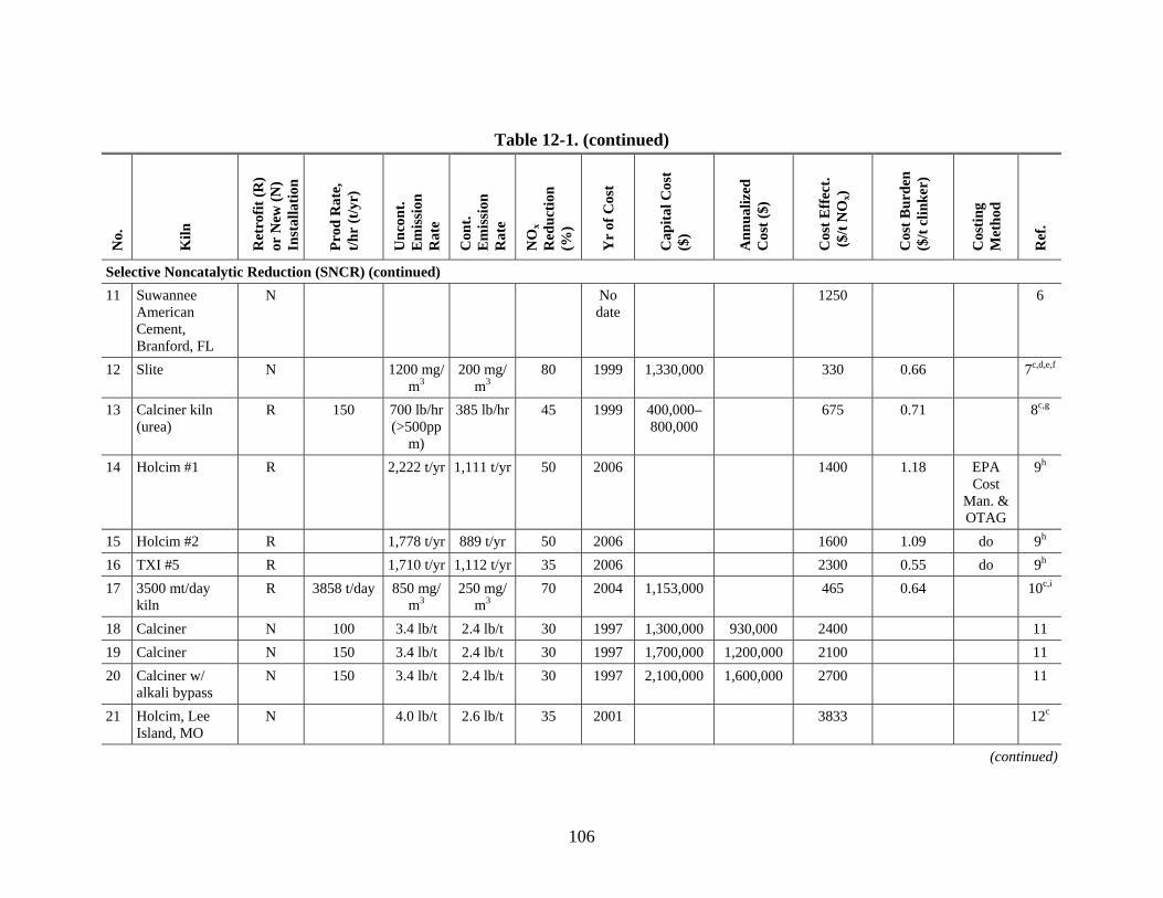
106
Table 12-1. (continued)
No.
Kiln
Ret
rofit
(R)
or N
ew (N
) In
stal
latio
n
Prod
Rat
e,
t/hr
(t/y
r)
Unc
ont.
Em
issi
on
Rat
e
Con
t. E
mis
sion
R
ate
NO
x R
educ
tion
(%)
Yr
of C
ost
Cap
ital C
ost
($)
Ann
ualiz
ed
Cos
t ($)
Cos
t Eff
ect.
($/t
NO
x)
Cos
t Bur
den
($/t
clin
ker)
Cos
ting
Met
hod
Ref
.
Selective Noncatalytic Reduction (SNCR) (continued) 11 Suwannee
American Cement, Branford, FL
N No date
1250 6
12 Slite N 1200 mg/ m3
200 mg/ m3
80 1999 1,330,000 330 0.66 7c,d,e,f
13 Calciner kiln (urea)
R 150 700 lb/hr (>500pp
m)
385 lb/hr 45 1999 400,000–800,000
675 0.71 8c,g
14 Holcim #1 R 2,222 t/yr 1,111 t/yr 50 2006 1400 1.18 EPA Cost
Man. & OTAG
9h
15 Holcim #2 R 1,778 t/yr 889 t/yr 50 2006 1600 1.09 do 9h 16 TXI #5 R 1,710 t/yr 1,112 t/yr 35 2006 2300 0.55 do 9h 17 3500 mt/day
kiln R 3858 t/day 850 mg/
m3 250 mg/
m3 70 2004 1,153,000 465 0.64 10c,i
18 Calciner N 100 3.4 lb/t 2.4 lb/t 30 1997 1,300,000 930,000 2400 11 19 Calciner N 150 3.4 lb/t 2.4 lb/t 30 1997 1,700,000 1,200,000 2100 11 20 Calciner w/
alkali bypass N 150 3.4 lb/t 2.4 lb/t 30 1997 2,100,000 1,600,000 2700 11
21 Holcim, Lee Island, MO
N 4.0 lb/t 2.6 lb/t 35 2001 3833 12c
(continued)

107
Table 12-1. (continued) N
o.
Kiln
Ret
rofit
(R)
or N
ew (N
) In
stal
latio
n
Prod
Rat
e,
t/hr
(t/y
r)
Unc
ont.
Em
issi
on
Rat
e
Con
t. E
mis
sion
R
ate
NO
x R
educ
tion
(%)
Yr
of C
ost
Cap
ital C
ost
($)
Ann
ualiz
ed
Cos
t ($)
Cos
t Eff
ect.
($/t
NO
x)
Cos
t Bur
den
($/t
clin
ker)
Cos
ting
Met
hod
Ref
.
Selective Noncatalytic Reduction (SNCR) (continued) 22 Drake Cement,
AZ N 840 t/yr 588 t/yr 30 2004 1,060,000 4211 13 c
23 Drake Cement, AZ
N 840 t/yr 588 t/yr 30 2003 1,400,000 1,130,000 4480 14 c
24 Florida Rock, Newberry, FL
R 4.0 lb/t 2.0 lb/t 50 2003 0.82 15 c
25 Florida Rock, Newberry, FL
R 3.5 lb/t 2.0 lb/t 43 2003 0.60 15 c
26 Florida Rock, Newberry, FL
R 3.5 lb/t 2.4 lb/t 43 2003 0.50 15 c
27 IEEE Mtg R 400–800 t/yr
2001 360,000–720,000
360,000–720,000
900–1800 16 c
28 Proposed kiln, CEMEX #3, FL
N 3850 t/day 3.5 lb/t 1.95 lb/t 2005 350,000 (0.20–0.25/t
clinker)
0.40–0.65/ t clinker
470–500 17c,j
29 German National Expert Group
Unk. 500 mg/Nm3
2006 726,000 363 0.42 21cd p
30 German National Expert Group
Unk. 200 mg/Nm3
2006 1,210,000 495 0.92 21cd p
31 3500 mt/day kiln
Unk. 3858 t/day 850 mg/m3
250 mg/m3
71 2006 1,153,000 1,500,000 465 1.11 22, 23 cdq
(continued)

108
Table 12-1. (continued)
No.
Kiln
Ret
rofit
(R)
or N
ew (N
) In
stal
latio
n
Prod
Rat
e,
t/hr
(t/y
r)
Unc
ont.
Em
issi
on
Rat
e
Con
t. E
mis
sion
R
ate
NO
x R
educ
tion
(%)
Yr
of C
ost
Cap
ital C
ost
($)
Ann
ualiz
ed
Cos
t ($)
Cos
t Eff
ect.
($/t
NO
x)
Cos
t Bur
den
($/t
clin
ker)
Cos
ting
Met
hod
Ref
.
Selective Catalytic Reduction (SCR) 32 Holcim #1 R 2,222 t/yr
(3.4 lb/t)333 t/yr
(0.50 lb/t)
85 2006 1600 2.36 EPA Cost Man.
9h
33 Holcim #2 R 1,778 t/yr(2.7 lb/t)
267 t/yr (0.41 lb/t)
85 2006 1900 2.00 Do 9h
34 TXI #5 R 1,710 t/yr(1.4 lb/t)
342 t/yr (0.27 lb/t)
80 2006 2000 1.00 Do 9h
35 3500 mt/day kiln
R 3858 t/day 850 mg/ m3
250 mg/ m3
70 2004 8,320,000 1230 1.69 10c,i
36 Model R 100 1360 t/yr 270 t/yr 80 1992 19,300,000 5,300,000 4900 --k 1 37 Model R 150 2040 t/yr 410 t/yr 80 1992 24,600,000 7,180,000 4400 --k 1 38 Kiln R 70–90+ 2004 1500–2000 3c 39 Kiln R 70
(529,000 t/yr)
800 mg/ m3
200 mg/ m3
2004 1.21 18c,l
40 Suwannee American
N 127 (1,055,000
t/yr)
1320 t/yr (2.5 lb/t)
898 t/yr (1.7 lb/t)
32 2004 4,600,000 9,100,000 21,000 (5,400 without
reheating costs)
8.64 (2.18 without
reheating costs)
Similar to EPA
Cost Man
19c,m
(continued)
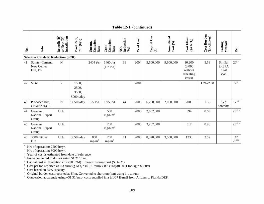
109
Table 12-1. (continued) N
o.
Kiln
Ret
rofit
(R)
or N
ew (N
) In
stal
latio
n
Prod
Rat
e,
t/hr
(t/y
r)
Unc
ont.
Em
issi
on
Rat
e
Con
t. E
mis
sion
R
ate
NO
x R
educ
tion
(%)
Yr
of C
ost
Cap
ital C
ost
($)
Ann
ualiz
ed
Cos
t ($)
Cos
t Eff
ect.
($/t
NO
x)
Cos
t Bur
den
($/t
clin
ker)
Cos
ting
Met
hod
Ref
.
Selective Catalytic Reduction (SCR) 41 Sumter Cement,
New Center Hill, FL
N 2404 t/yr 1460t/yr (1.7 lb/t)
39 2004 5,500,000 9,600,000 10,200 (3,000 without
reheating costs)
5.58 Similar to EPA
Cost Man.
20c,n
42 VDZ R 1500, 2500, 3500,
5000 t/day
2004 1.21–2.30 5c,d
43 Proposed kiln, CEMEX #3, FL
N 3850 t/day 3.5 lb/t 1.95 lb/t 44 2005 6,200,000 2,000,000 2000 1.55 See footnote
17c,o
44 German National Expert Group
Unk. 500 mg/Nm3
2006 2,662,000 594 0.69 21cd p
45 German National Expert Group
Unk. 200 mg/Nm3
2006 3,267,000 517 0.96 21cd p
46 3500 mt/day kiln
Unk. 3858 t/day 850 mg/m3
250 mg/m3
71 2006 8,320,000 3,500,000 1230 2.52 22 23cdq
a Hrs of operation: 7500 hr/yr. b Hrs of operation: 8000 hr/yr. c Year of cost is estimated from date of reference. d Euros converted to dollars using $1.21/Euro. e Capital cost = installation cost ($0.67M) + reagent storage cost ($0.67M) f Cost per ton reported as 0.3 euro/kg NOx = ($1.21/euro x 0.3 euro)/(0.0011 ton/kg = $330/t) g Cost based on 85% capacity h Original burden cost reported as $/mt. Converted to short ton (ton) using 1.1 ton/mt. i Conversion apparently using ~$1.31/euro; costs supplied in a 2/1/07 E-mail from Al Linero, Florida DEP.
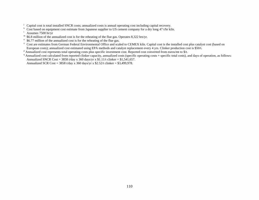
110
j Capital cost is total installed SNCR costs; annualized costs is annual operating cost including capital recovery. k Cost based on equipment cost estimate from Japanese supplier to US cement company for a dry long 47 t/hr kiln. l Assumes 7500 hr/yr m $6.8 million of the annualized cost is for the reheating of the flue gas. Operates 8,322 hrs/yr. n $6.77 million of the annualized cost is for the reheating of the flue gas. o Cost are estimates from German Federal Environmental Office and scaled to CEMEX kiln. Capital cost is the installed cost plus catalyst cost (based on
European costs); annualized cost estimated using EPA methods and catalyst replacement every 4 yrs. Clinker production cost is $50/t. p Annualized cost represents total operating costs plus specific investment cost. Reported cost converted from euros/mt to $/t. q Annualized cost calculated from reported clinker capacity, annualized costs (specific operating costs + specific total costs), and days of operation, as follows:
Annualized SNCR Cost = 3858 t/day x 360 days/yr x $1.11/t clinker = $1,541,657. Annualized SCR Cost = 3858 t/day x 360 days/yr x $2.52/t clinker = $3,499,978.

111
Table 12-2. SNCR and SCR Costs for Preheater/Precalciner Kilns in 2005 Dollars
No. Kiln Prod Rate, t/hr (t/yr)
Uncont. Emission
Rate
Cont. Emission
Rate
NOx Reduction
(%)
Original Yr of Cost
Annualized Cost ($)
Cost Effect. ($/t NOx)
Cost Burden ($/t
clinker)
Costing Method Ref.
Selective Noncatalytic Reduction (SNCR)
1 Model (urea) 100 (750000) 1360 t/yr 680 t/yr 50 1992 754,192 1,109 1.01 1
2 Model (urea) 150 (1125000)
2040 t/yr 1020 t/yr 50 1992 1,037,307 1,017 0.93 1
3 Model (NH3) 100 (750000)
1360 t/yr 680 t/yr 50 1992 822,422 1,209 1.10 1
4 Model (NH3) 150 (1125000)
2040 t/yr 1020 t/yr 50 1992 1,109,328 1,087 0.98 1
5 Kiln A 92 (736000)
340 lb/hr 204 lb/hr 40 1997 678,375 1,211 0.92 OAQPS Cost Manual
2
6 Kiln B 133 (1064000)
510 lb/hr 306 lb/hr 40 1997 2,422,768 3,028 2.28 OAQPS Cost Manual
2
7 Kiln 10–50 2004 327–2,635 3
8 Kiln (NH3 reagent) 1998 0.55–1.08 4
9 Kiln (urea reagent) 1998 1.60–2.52 4
10 4 Kilns 1500, 2500, 3500,
5000 t/day
2004 1800–2400 0.64–0.90 5
11 Suwannee American Cement, Branford, FL
No date 6
(continued)
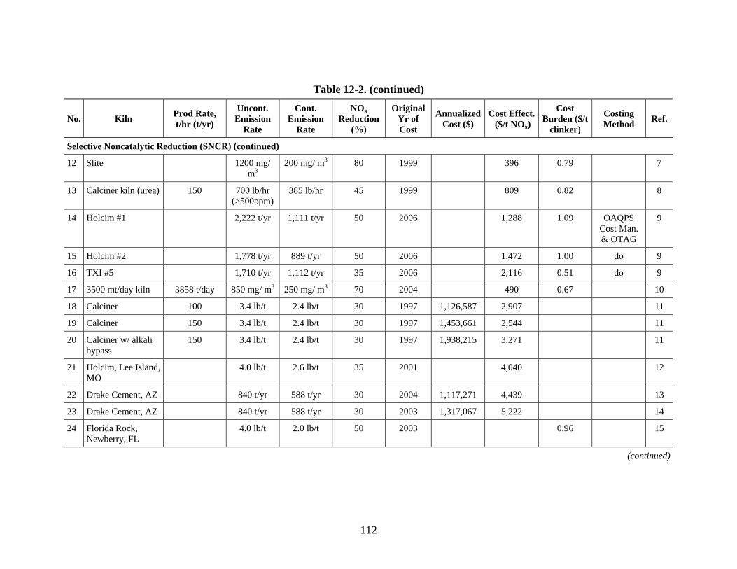
112
Table 12-2. (continued)
No. Kiln Prod Rate, t/hr (t/yr)
Uncont. Emission
Rate
Cont. Emission
Rate
NOx Reduction
(%)
Original Yr of Cost
Annualized Cost ($)
Cost Effect. ($/t NOx)
Cost Burden ($/t
clinker)
Costing Method Ref.
Selective Noncatalytic Reduction (SNCR) (continued)
12 Slite 1200 mg/ m3
200 mg/ m3 80 1999 396 0.79 7
13 Calciner kiln (urea) 150 700 lb/hr (>500ppm)
385 lb/hr 45 1999 809 0.82 8
14 Holcim #1 2,222 t/yr 1,111 t/yr 50 2006 1,288 1.09 OAQPS Cost Man. & OTAG
9
15 Holcim #2 1,778 t/yr 889 t/yr 50 2006 1,472 1.00 do 9
16 TXI #5 1,710 t/yr 1,112 t/yr 35 2006 2,116 0.51 do 9
17 3500 mt/day kiln 3858 t/day 850 mg/ m3 250 mg/ m3 70 2004 490 0.67 10
18 Calciner 100 3.4 lb/t 2.4 lb/t 30 1997 1,126,587 2,907 11
19 Calciner 150 3.4 lb/t 2.4 lb/t 30 1997 1,453,661 2,544 11
20 Calciner w/ alkali bypass
150 3.4 lb/t 2.4 lb/t 30 1997 1,938,215 3,271 11
21 Holcim, Lee Island, MO
4.0 lb/t 2.6 lb/t 35 2001 4,040 12
22 Drake Cement, AZ 840 t/yr 588 t/yr 30 2004 1,117,271 4,439 13
23 Drake Cement, AZ 840 t/yr 588 t/yr 30 2003 1,317,067 5,222 14
24 Florida Rock, Newberry, FL
4.0 lb/t 2.0 lb/t 50 2003 0.96 15
(continued)
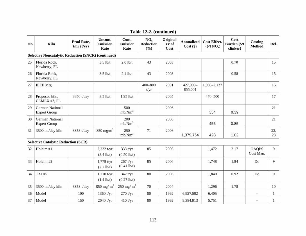
113
Table 12-2. (continued)
No. Kiln Prod Rate, t/hr (t/yr)
Uncont. Emission
Rate
Cont. Emission
Rate
NOx Reduction
(%)
Original Yr of Cost
Annualized Cost ($)
Cost Effect. ($/t NOx)
Cost Burden ($/t
clinker)
Costing Method Ref.
Selective Noncatalytic Reduction (SNCR) (continued)
25 Florida Rock, Newberry, FL
3.5 lb/t 2.0 lb/t 43 2003 0.70 15
26 Florida Rock, Newberry, FL
3.5 lb/t 2.4 lb/t 43 2003 0.58 15
27 IEEE Mtg 400–800 t/yr
2001 427,000–855,001
1,069–2,137 16
28 Proposed kiln, CEMEX #3, FL
3850 t/day 3.5 lb/t 1.95 lb/t 2005 470–500 17
29 German National Expert Group
500 mb/Nm3
2006 334 0.39
21
30 German National Expert Group
200 mb/Nm3
2006 455 0.85
21
31 3500 mt/day kiln 3858 t/day 850 mg/m3 250 mb/Nm3
71 2006 1,379,764 428 1.02
22, 23
Selective Catalytic Reduction (SCR)
32 Holcim #1 2,222 t/yr (3.4 lb/t)
333 t/yr (0.50 lb/t)
85 2006 1,472 2.17 OAQPS Cost Man.
9
33 Holcim #2 1,778 t/yr (2.7 lb/t)
267 t/yr (0.41 lb/t)
85 2006 1,748 1.84 Do 9
34 TXI #5 1,710 t/yr (1.4 lb/t)
342 t/yr (0.27 lb/t)
80 2006 1,840 0.92 Do 9
35 3500 mt/day kiln 3858 t/day 850 mg/ m3 250 mg/ m3 70 2004 1,296 1.78 10
36 Model 100 1360 t/yr 270 t/yr 80 1992 6,927,582 6,405 -- 1
37 Model 150 2040 t/yr 410 t/yr 80 1992 9,384,913 5,751 -- 1
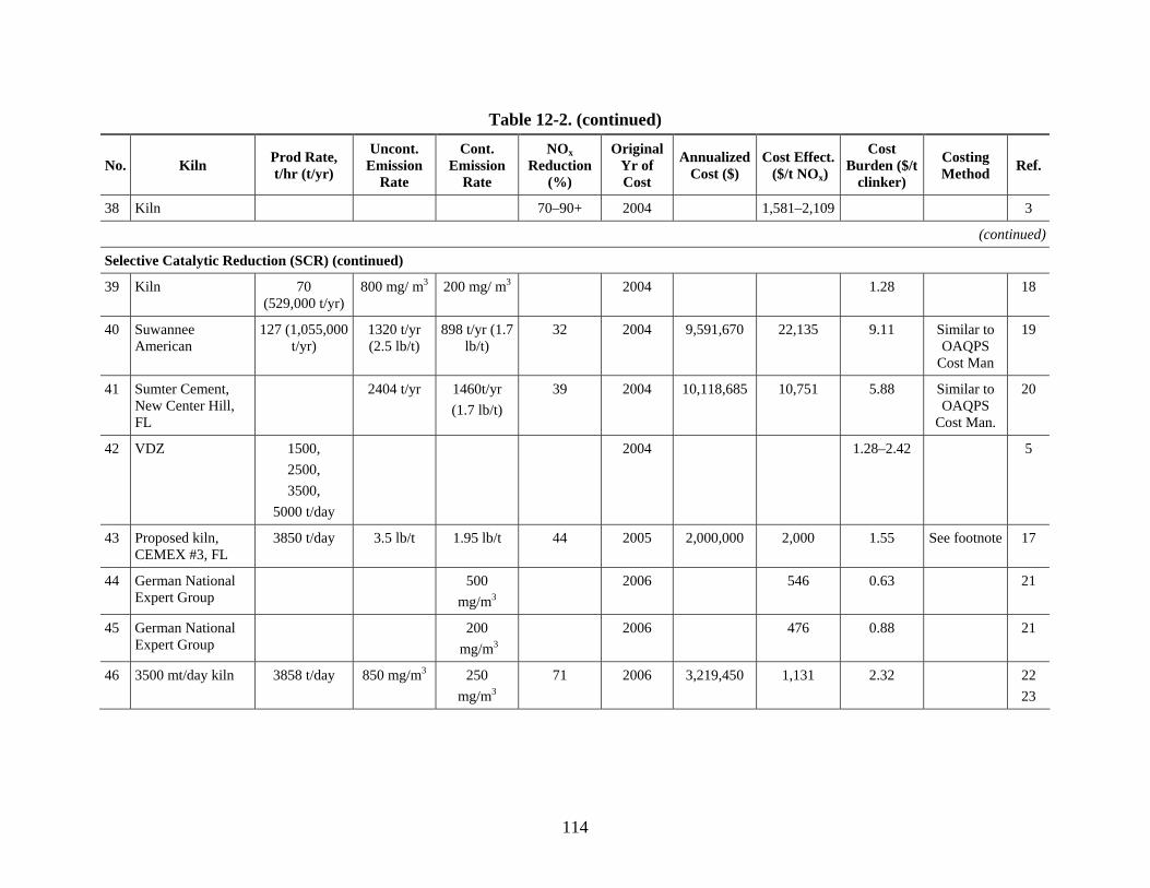
114
Table 12-2. (continued)
No. Kiln Prod Rate, t/hr (t/yr)
Uncont. Emission
Rate
Cont. Emission
Rate
NOx Reduction
(%)
Original Yr of Cost
Annualized Cost ($)
Cost Effect. ($/t NOx)
Cost Burden ($/t
clinker)
Costing Method Ref.
38 Kiln 70–90+ 2004 1,581–2,109 3
(continued)
Selective Catalytic Reduction (SCR) (continued)
39 Kiln 70 (529,000 t/yr)
800 mg/ m3 200 mg/ m3 2004 1.28 18
40 Suwannee American
127 (1,055,000 t/yr)
1320 t/yr (2.5 lb/t)
898 t/yr (1.7 lb/t)
32 2004 9,591,670 22,135 9.11 Similar to OAQPS
Cost Man
19
41 Sumter Cement, New Center Hill, FL
2404 t/yr 1460t/yr (1.7 lb/t)
39 2004 10,118,685 10,751 5.88 Similar to OAQPS
Cost Man.
20
42 VDZ 1500, 2500, 3500,
5000 t/day
2004 1.28–2.42 5
43 Proposed kiln, CEMEX #3, FL
3850 t/day 3.5 lb/t 1.95 lb/t 44 2005 2,000,000 2,000 1.55 See footnote 17
44 German National Expert Group
500 mg/m3
2006 546 0.63 21
45 German National Expert Group
200 mg/m3
2006 476 0.88 21
46 3500 mt/day kiln 3858 t/day 850 mg/m3 250 mg/m3
71 2006 3,219,450 1,131 2.32 22 23

115
12.1 REFERENCES
1. U.S. Environmental Protection Agency. Alternative Control Techniques Document – NOx
Emissions from Cement Manufacturing. EPA-453/R-94-004. March 1994. Available at www.epa.gov/ttn/cata/dir1/cement.pdf.
2. U.S. Environmental Protection Agency. NOx Control Technologies for the Cement Industry. Prepared by EC/R Incorporated. September 19, 2000. Available at www.epa.gov/ttn/naaqs/ozone/ozonetech/cement_nox_update_09152000.pdf.
3. Midwest Regional Planning Organization. Interim White Paper – Midwest RPO Candidate Control Measures. March 2005.
4. CEMBUREAU. Best Available Techniques for Cement Industry. December 1999.
5. VDZ (German Cement Works Association). Environmental protection in cement manufacture. VDZ Activity Report 2003 –2005. 2005.
6. Suwannee American Cement, Branford, FL. Best Available Control Technology (BACT) Determination. Undated.
7. Reduction of NOx with SNCR Technology at Slite Cement Program, March 2000, Per Junker, Director of Environmental Protection, County Administration of Gotland, Organization Committee on NO-N2O Emissions Control, November 17, 2000.
8. NESCAUM. Status Report on NOx Controls – Technologies and Cost Effectiveness. December 2000.
9. Texas Commission on Environmental Quality. Assessment of NOx Emissions Reduction Strategies for Cement Kilns – Ellis County. Prepared by ERG Inc. July 14, 2006. Available at www.tceq.state.tx/us/implementation/air/sip/BSA_settle.html.
10. VDZ. Technical and Scientific Cement Conference. The Present State of NOx Abatement with the SNCR Process, Nuremburg, Germany. November 27, 2005.
11. Portland Cement Association. Report on NOx Formation and Variability in Portland Cement Kiln Systems Potential Control Techniques and Their Feasibility and Cost Effectiveness. PCA R&D Serial No. 2227. Prepared by Penta Engineering Corporation. 1999.
12. Holcim. Project Review of Construction Permit. Lee Island, MO. May 31, 2002.
13. Letter from Drake Cement to Arizona Department of Environmental Quality. February 25, 2005.
14. Arizona Department of Environmenttal Quality. Drake Cement. Class 1 Air Permit Application. June 9, 2004.
116
15. Florida Rock Industries. SNCR Test Report. Newberry, FL. December 2004.
16. Hower, J. Cement Kiln Application of Selective Non-Catalytic Reduction – Myth or Reality? Presented at IEEE Florida Meeting, May 2002.
17. Florida Department of Environmental Protection. Report in Support of an Application for a PSD Construction Permit Review – CEMEX, Inc., Kiln 3. October 12, 2006. Available at www.dep.state.fl.us/Air/permitting/construction/cemex.htm.
18. Linero, A. SNCR NOx at US Cement Plants. Is SCR Close Behind? Paper #638 presented at the AWMA Annual Conference. June 2005.
19. Florida Department of Environmental Protection. Technical Evaluation and Preliminary Determination – Suwannee American Cement, Branford, FL. Permit Modification to Increase Production, Inject Fly Ash into Calciner, Install a Selective Non-Catalytic Reduction System. DEP File No. 1210465-011-AC. Division of Air Resources Management. February 16, 2005.
20. Florida Department of Environmental Protection. BACT Application. Sumter Cement, New Center Hill, FL. September 2005.
21. German National Expert Group. German Contribution to the Review of the Reference Document on Best Available Techniques in the Cement and Lime Manufacturing Industries. June 1, 2006.
22. Letter from A. Linero, Florida Department of Environmental Protection, to B. Neuffer, U.S. Environmental Protection Agency. Comments on Draft Alternative Control Techniques Document Update – NOx Emissions from New Cement Kilns (June 2006). July 18, 2007.
23. Scur, P., Dipl. Ing.; Hoppe, H., Ph.D., The Present State of NOx Abatement with the SNCR Process. Cement International, No. 2/2006.
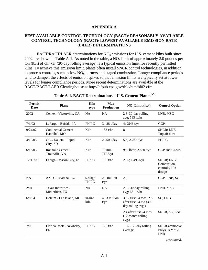
A-1
APPENDIX A
BEST AVAILABLE CONTROL TECHNOLOGY (BACT)/ REASONABLY AVAILABLE CONTROL TECHNOLOGY (RACT)/ LOWEST AVAILABLE EMISSION RATE
(LAER) DETERMINATIONS
BACT/RACT/LAER determinations for NOx emissions for U.S. cement kilns built since 2002 are shown in Table A-1. As noted in the table, a NOx limit of approximately 2.0 pounds per ton (lb/t) of clinker (30-day rolling average) is a typical emission limit for recently permitted kilns. To achieve this emission limit, plants often install SNCR control technologies, in addition to process controls, such as low NOx burners and staged combustion. Longer compliance periods tend to dampen the effects of emission spikes so that emission limits are typically set at lower levels for longer compliance periods. More recent determinations are available at the RACT/BACT/LAER Clearinghouse at http://cfpub.epa.gov/rblc/htm/bl02.cfm.
Table A-1. BACT Determinations – U.S. Cement Plants1–3
Permit Date Plant Kiln
type Max
Production NOx Limit (lb/t) Control Option
2002 Cemex - Victorville, CA NA NA 2.8–30-day rolling avg; 583 lb/hr
LNB, MSC
7/1/02 LaFarge - Buffalo, IA PH/PC 3,488 t/day 4; 2546 t/yr GCP
9/24/02 Continental Cement - Hannibal, MO
Kiln 183 t/hr 8 SNCR; LNB; Top air duct
4/10/03 GCC Dakota - Rapid City, SD
Kiln 2,250 t/day 5.5; 2,267 t/yr PH/PC
6/13/03 Roanoke Cement -Troutville, VA
Kiln 1.3mm TIBS/yr
982 lb/hr; 2,850 t/yr GCP and CEMS
12/11/03 Lehigh - Mason City, IA PH/PC 150 t/hr 2.85; 1,496 t/yr SNCR; LNB; Combustion controls, kiln design
NA AZ PC - Marana, AZ 5-stage PH/PC
2.3 million t/yr
2.3 GCP, LNB, SC
2/04 Texas Industries - Midlothian, TX
NA NA 2.8 - 30-day rolling avg; 681 lb/hr
LNB. MSC
6/8/04 Holcim - Lee Island, MO in-line kiln
4.83 million t/yr
3.0 - first 24 mos; 2.8 after first 24 mo (30-day rolling avg.)
SC, LNB
2.4 after first 24 mos (12-month rolling avg.)
SNCR, SC, LNB
7/05 Florida Rock - Newberry, FL
PH/PC 125 t/hr 1.95 - 30-day rolling average
SNCR-ammonia; Polysius MSC; LNB
(continued)

A-2
Table A-1. (continued) Permit Date Plant Kiln
type Max
Production NOx Limit (lb/t) Control Option
4/5/05 Titan Cement - Pennsuco, FL
PH/PC 250 t/hr 2.17–30-day rolling average
LNB, SC
2/6/06 Sumter Cement – New Center Hill, FL
PH/PC 208 t/hr 1.95; 406 lb/hr - 30-day rolling avg
LNB, SC, SNCR
2/13/06 American Cement – Sumterville, FL
PH/PC 125 t/hr (24-hr rolling)
1.95; 244 lb/hr - 30-day rolling avg
LNB, SC, SNCR
7/7/05 Florida Crushed Stone - Brooksville, FL
PH/PC 125 t/hr 1.95 - 30-day rolling average
same as above
6/9/06 Suwannee American - Branford, FL
PH/PC 127 t/hr 1.95 - 30-day rolling average
same as above
4/12/06 Drake – AZ (Class I area) PH/PC 83 t/hr 95 lb/hr (hourly rolling 24 hr avg); 1.95 lb/t (daily rolling 30-day average)
same as above
GCP- Good Combustion Practices; LNB - Low NOx Burners; CEMS - Continuous Emission Monitoring Systems
REFERENCES 1. Arizona Department of Environmental Quality. Technical Support Document and
Statement of Basis for Construction of Drake Cement, L.L.C., Portland Cement Plant. Air Quality Permit Number 1001770. June 9, 2004. Available at www.azdeq.gov/download/ draketsd.pdf. Accessed March 6, 2007.
2. Florida Department of Environmental Protection. Report in Support of an Application for a PSD Construction Permit Review – Natural Resources of Central Florida, Inc. American Cement Company, Sumterville, FL. October 4, 2005. pp. 93–99. Available at www.dep.state.fl.us/Air/ permitting/construction/american.
3. Florida Department of Environmental Protection. Technical Determination. Sumter Cement Company. December 21, 2005.

United States Environmental Protection Agency
Office of Air Quality Planning and Standards Sector Policies and Programs Division
Research Triangle Park, NC
Publication No. EPA 453/R-07-006 November 2007