urban highway design (non-freeway)odot highway design manual urban highway design (non-freeway) §...
TRANSCRIPT
Chapter
6
URBAN HIGHWAY DESIGN
(NON-FREEWAY)

ODOT Highway Design Manual Urban Highway Design (Non-Freeway)
§ 6-1 - Introduction 6-1
6.1 INTRODUCTION
Designing urban highway projects presents designers with a variety of challenges. Designers must balance the needs of autos, trucks, transit, bicyclists, and pedestrians, while considering highway function, speed, safety, alignment, channelization, right of way, environmental impacts, land use impacts, and roadside culture. Urban highways can take several forms: freeways, expressways, arterials, collectors, and sometimes, local roads. This chapter will focus on urban expressways and arterials. Urban freeway design is discussed in Chapter 5, Urban and Rural Freeway Design. This chapter will discuss a variety of issues, concerns, and areas for consideration when designing urban highways not only as expressways, but also arterial highways in terms of specific highway segment designations of Special Transportation Areas (STA), Urban Business Areas (UBA) and Commercial Centers (CC). In addition, this chapter will discuss the design of non-designated highways categorized as Urban Fringe/Suburban, Developed and Traditional Downtown/Central Business District (CBD) locations. Appropriate design standards will be discussed for each of these segment designations and categories of urban highways. Many of the concepts in this chapter, including expressways, state highway classification system, and highway segment designations, are based on the 1999 Oregon Highway Plan (OHP) Land Use and Transportation policies. This chapter of the Highway Design Manual focusing on urban, non-freeway design dovetails nicely with ODOT’s policy on Practical Design and provides appropriate flexibility in urban highway design in relation to land use, context sensitive design and community based decision processes.
The majority of this chapter will describe the standards that are appropriate for the design of new construction or 4R type projects on different urban highways. These standards are contained in section 6.1 through section 6.3 and in Table 6-1, through Table 6-6. Section 6.4 of this chapter describes the ODOT 3R Urban Design Standards applicable to non-freeway urban highways. Section 6.5 discusses ODOT 1R standards (Non-Freeway) and Section 6.6 explains ODOT Single Function (SF) Urban Design Standards (Non-Freeway). Other important design elements included in urban highway design are bicycle, pedestrian and transit facilities. Bicycle and pedestrian design elements are discussed throughout the individual chapter sections as needed and more specifically in Chapter 13, pedestrian and Bicycle and in Appendix L, Oregon Bicycle and Pedestrian Design Guide, while Chapter 12 provides guidelines for public transportation.
6.1.1 URBAN EXPRESSWAYS
Urban expressways are generally high-speed, limited access facilities whose function is to move both inter-urban and intra-urban traffic. Mobility is a high priority. Expressways may often serve as major freight corridors as well as being designated as an OHP Freight Route. They are often part of the National Highway System (NHS). Private property access is discouraged in favor of through mobility importance. Access is normally restricted to at-grade signalized and unsignalized public road intersections or interchanges. At-grade signalized intersections may
ODOT Highway Design Manual Urban Highway Design (Non-Freeway)
§ 6-1 - Introduction 6-2
provide full access. However, at-grade, unsignalized intersections should be considered carefully and for safety reasons, it is desirable to limit them to a right-in, right-out condition. In areas where there is no other reasonable access, private approach roads may be allowed. Private approach road connections to expressways need to be considered and evaluated carefully in order to minimize safety risks and to address driver expectancy related to the context and roadside culture and should also be limited to a right-in, right-out condition. Expressways may have a mixture of at-grade intersections and interchanges. However, the mixing of at-grade intersections with grade separated interchanges in proximity to each other should be kept to a minimum. Drivers may become confused in their perception of expectations at the different connection styles causing undesirable actions on their part as they interact with other vehicles entering or leaving the roadway. Some expressways may become freeways in the future and therefore should be designed, operated, and managed at the highest level to ensure long-term operations. The transitioning of urban roadways to expressways should take into account the long-term plan for the roadway, which can impact the design of the facility. Section 6.2 and Table 6-1 provide standards for the design of expressways.
6.1.2 URBAN ARTERIALS
State highways through urban areas are part of the state highway network and provide connectivity to rural areas and adjacent communities and urban areas. In addition, they serve as arterials for the particular community where they reside and often are the major or principal arterial in that community. The primary function of these arterials is to serve major through traffic movements with a high level of mobility and provide limited land access. Arterials carry the highest traffic volumes and serve as the conduit for longer internal and external trips as well as for intra-area travel between city centers. However, arterials often traverse major city centers such as traditional downtowns, central business districts or regional commercial centers. In addition, due to existing land use and development patterns, arterials often are adjacent to areas of intense auto oriented development. These different land use designations can significantly affect the design of a particular arterial highway. Issues such as pedestrian movement, transit accommodation, bicycles, freight routes, through traffic capacity, as well as the type of land use designation must all be considered when designing urban arterials. In order to address conflicts that arise when designing arterial highways in these locations, ODOT has developed a process to identify special areas along a highway where context sensitive designs and practical solutions are needed. Criteria have been developed for specific Highway Segment Designations outlined in the 1999 Oregon Highway Plan (OHP) and for Non-Designated Urban Highway Segments as well as for other OHP Special Overlay areas. Separate definitions and guidelines have been established and are outlined in this section. Highway Segment Designations include Special Transportation Areas, Urban Business Areas and Commercial Centers. Non-Designated Urban Highways are divided into groups by context and include Urban Fringe/Suburban sections, Developed sections and Traditional Downtown/Central Business District sections. OHP Special Overlays include Freight Routes, Lifeline Routes and Scenic Byway.
Since arterials can traverse many different types of areas within urban growth boundaries, speed is often a major concern. Transitioning design and operating speeds of an arterial as it enters an urban area on the fringe, to areas of normal urban density and then to compact town
ODOT Highway Design Manual Urban Highway Design (Non-Freeway)
§ 6-1 - Introduction 6-3
centers, is often a challenge for a designer. However, these transition areas are often the most critical design consideration for an urban arterial as it travels through an urban area. The designer is encouraged to utilize visual cues such as landscaping, roadside amenities, visual aesthetics, and design elements to help achieve the appropriate speed transitions for these areas and roadway sections.
Another important aspect to Urban Arterial design is determining the appropriate design speed. The selection of design speed is dependent on many factors that need to be carefully considered and evaluated. Section 5.2.1 provides information on selecting design speeds that should be reviewed prior to selection of a design speed for a particular project. After selection of an appropriate design speed, the following sections are used to provide standard design criteria based on the selected design speed for the different types of urban highways (OHP Highway Segment Designations and Non-Designated Urban Highways)
6.1.2.1 1999 OHP HIGHWAY SEGMENT DESIGNATIONS
Arterials can run adjacent to or traverse through many different types of land use areas. The function and desired attributes of the roadway may differ from area to area. The 1999 OHP identifies four types of highway segment designations in relation to adjacent land uses. Three of the four are listed below.
1 Special Transportation Areas (STAs; see Section 6.2.2)
2. Urban Business Areas (UBAs; see Section 6.2.3)
3. Commercial Centers (CCs; see Section 6.2.4)
These special highway segment designations express different goals and attributes from the rest of the urban arterial system. Although some urban environments may look similar to one of these special designated areas, they may not be classified the same. The OHP contains requirements that must be met in order for an area to receive these special designations. The designer needs to coordinate and work with the Region planner and/or Project Leader to identify the location of any special highway segment designations as well as applicable corridor, refinement, or Transportation System Plans (TSPs). These plans will provide valuable information and direction to the designer. Design standards for a specific OHP segment designation shall only be used if the area has received formal approval of the designation by the Oregon Transportation Commission (OTC) and be in an acknowledged TSP. The OHP designation should be reviewed for both 3R and 4R projects.
6.1.2.2 NON-DESIGNATED URBAN HIGHWAYS
The Non-Designated Highway is the fourth highway segment designation listed in the 1999 OHP. Non-designated Urban Highways are those highways within urban growth boundaries that are not designated as Interstate Highways, Expressways, STAs, UBAs, or Commercial Centers. The objective of urban highways is to efficiently move through traffic while also
ODOT Highway Design Manual Urban Highway Design (Non-Freeway)
§ 6-1 - Introduction 6-4
meeting the access needs of nearby properties. The urban highway designation is a very broad classification as urban arterials can traverse many different areas and each area has unique attributes that affect the appropriate design. For example, some downtown environments may have a similar look and feel as an STA, but have not been designated as an STA. This type of environment cannot use the STA design standards, but should be treated differently than urban areas with strip development or higher speed urban fringe areas. The OHP does not create sub-categories within the Non-Designated Urban Highways segment. To assist the designer, this manual breaks this urban highway designation into general categories that do not meet the requirements or intent of the other highway segment designations. These categories are shown below.
1. Urban Fringe/Suburban (See Section 6.3.1)
2. Developed (See Section 6.3.2).
3. Traditional Downtowns/Central Business Districts (CBD; see Section 6.3.3)
6.1.2.3 OTHER OHP SPECIAL OVERLAYS
In conjunction with the functions outlined in the previous sections, urban highway facilities may also be tasked with providing special functionality. The OHP describes these other special highway designations that must also be considered when designing urban highways. They are included in the following list.
1. Freight Route (See Section 6.2.5.1)
2. Lifeline Route (See Section 6.2.5.2)
3. Scenic Byway Route (See Section 6.2.5.3)
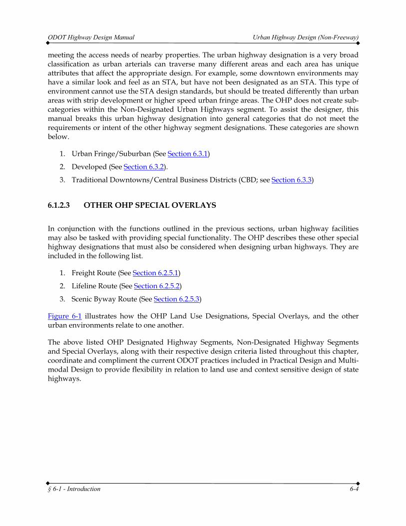
Figure 6-1 illustrates how the OHP Land Use Designations, Special Overlays, and the other urban environments relate to one another.
The above listed OHP Designated Highway Segments, Non-Designated Highway Segments and Special Overlays, along with their respective design criteria listed throughout this chapter, coordinate and compliment the current ODOT practices included in Practical Design and Multi-modal Design to provide flexibility in relation to land use and context sensitive design of state highways.
ODOT Highway Design Manual Urban Highway Design (Non-Freeway)
§ 6-1 - Introduction 6-5
Figure 6-1: OHP Land Use Designation Overlay
6.1.2.4 ROLE OF PLANNING DOCUMENTS AND DESIGN CRITERIA
Planning documents such as corridor plans, refinement plans, and regional or local transportation system plans and facility plans like Interchange Area Management Plans (IAMPs) provide valuable guidance to designers. These documents have undergone extensive public involvement to select the type and level of infrastructure improvements that address the identified problems. The designer needs to be aware of and understand the context of the recommendations contained in these planning documents when preparing project designs. The Region Planning Manager should be contacted to help identify and interpret the information in these plans. In the case of Interchange Area Management Plans (IAMP) and other types of planned facility designs the Chief Engineer’s approval is required.
The types of plans discussed above are all plans adopted by local jurisdictions and/or the Oregon Transportation Commission. Therefore, transportation improvement projects must be consistent with these adopted plans. Design elements and features on State Highways must meet the ODOT Design Standards. These standards are in the Highway Design Manual. The Department cannot construct, fund or permit design elements or features that are not up to standards unless a Design Exception has been approved by the State Traffic-Roadway Engineer. Because pertinent information may not be available in these planning processes, exceptions to design standards are typically processed during project development and are approved in writing at that time. Similarly, any traffic control changes such as traffic signals, signing, or
ODOT Highway Design Manual Urban Highway Design (Non-Freeway)
§ 6-1 - Introduction 6-6
striping must have the written approval of the State Traffic-Roadway Engineer.
However, since Transportation Plans commonly have design elements and features of State Highways discussed in them, there are times when deviations to design standards need to be addressed during planning to ensure they are incorporated in the final project development when the planning documents are actually implemented. These design elements and features may include roadway cross-sections, centerline alignments, interchange layout configurations, bike lanes, sidewalks, shoulders, and shared use paths.
Issues corresponding to interpretation can occur when the design elements and features shown in Transportation Plans differ from those in the Highway Design Manual. Since ODOT prepared, funded or reviewed the plan, local government or the public often think that the design elements and features shown have been approved by ODOT and that ODOT will construct or allow the construction of these elements and features according to the plan. Unless a Design Exception has been previously sought, future projects linked to an adopted plan may be required to follow ODOT standards regardless of the design elements or features that may have been identified in the plan.
To avoid this problem, planning studies should follow ODOT Design Standards or seek a Design Exception. Chapter 14 of the Highway Design Manual describes the Design Exception process. Below are some guidelines for inclusion of design elements and features in planning documents that include State Highways:
1. Don’t show specific dimensions for any design elements.
2. If you do show dimensions, they should be to ODOT standards.
3. For planning studies that have non-standard design elements and features that may be constructed within five years, obtain a Design Exception before incorporation of dimensions into the final plan.
4. For planning studies that have non-standard design elements and features that may be constructed within five to ten years, submit a Draft Design Exception request and obtain a written indication or concurrence that a Design Exception is warranted and would probably be approved from the State Traffic-Roadway Engineer before incorporation of dimensions into the final plan.
5. Planning documents cannot select an alternative with non-standard elements or features as the preferred alternative unless a Design Exception has been obtained or the State Traffic-Roadway Engineer has indicated that one would probably be approved.
6. In consideration of overall safety along a highway segment, proposed cross-sections with multiple non-standard design elements should be avoided. When avoidance is not possible, the cumulative effect on operations and safety of introducing multiple non-standard elements in the same cross-section must be considered and evaluated carefully.
The link to the Highway Design Manual, Chapter 14 (Design Exceptions) is provided below. Chapter 14 - Design Exception Process
ODOT Highway Design Manual Urban Highway Design (Non-Freeway)
§ 6-1 - Introduction 6-7
Planning documents are often long range. Their use is for planning land use and infrastructure options over 15 and 20 year time frames or more. These long-term plans designate future areas of development. They may designate areas such as UBAs or STAs as future nodes. Designers must ensure the safety of all users when designing projects that travel through these future areas of development. Consideration should be given to long range planning efforts and how those efforts impact the proposed roadway projects. The designer should work with the Project Team, Region Planning Manager, and/or Area Manager to gain a better understanding of the planning efforts and processes completed or underway for a particular area.
6.1.2.5 TRANSITIONS
One of the most important elements of urban highway design is the transition area. Transition areas occur when a rural highway enters an urban area, when urban expressways enter slower speed urban centers or between other different urban environments such as between a UBA and an STA. The types and treatments of transitions will vary depending upon the type of transition.
A very common type of transition is the transition from a rural high speed highway to an urban highway. In many small communities or rural communities, the length of transition is very short. The main emphasis for a designer in these areas is to try to change the look and feel of the highway segment. This often involves establishing urban design features such as sidewalks, buffer strips, marked crosswalks, landscaping, bike lanes, raised medians, and illumination. Generally these types of features will portray to the motorist that they are entering a changing environment that is urbanized and requires slower speeds and greater attention to pedestrians, bicyclists, and transit vehicles. Designing for the context of the roadway can also include designing for the intended operating speed of a roadway segment. Speed is part of the context of a roadway. In some of these transition areas, reducing the cross section width may be appropriate an option, but is only one of many ways to help transition speeds. Changing the roadway culture, including elements outside of the roadway section, can also help to create transition areas. Any modifications of the actual cross section elements should be consistent with the design standards for a particular urban environment (STA, UBA, Developed, Urban Fringe/Suburban areas). Many of these standards are also applicable to transitioning from a high-to-moderate speed urban expressway to other urban environments. The key message to send to motorists is that the culture and function of the highway has changed.
Other types of transitions occur between different urban environments such as between an UBA and an STA, or an Urban Fringe/Suburban area to a UBA, or other combinations. Again, even for these transitions, a message should be sent to the motorist that something is different. For example transition areas entering a UBA might include features such as buffer strips, change of median style, different curb type, landscaping and/or other roadside features, or change of sidewalk style or width. Generally, the land use patterns of these areas, with some minor design features, will be sufficient to establish the message “you are entering a developed business district.” In some cases, modifying the cross sectional elements may also be an appropriate option. These elements may include reduced shy distances, and/or narrower shoulder/bike lane, lane widths, or median widths. The design should reflect the standard for the specific
ODOT Highway Design Manual Urban Highway Design (Non-Freeway)
§ 6-1 - Introduction 6-8
urban environment as described later in this section.
Transitions to an STA or downtown/central business district type of environment are very important. These areas are often very low speed and controlling operating speeds is important to the success of these areas. A recommended approach to dealing with transitions into STA or downtown environments is the use of a “Gateway” approach. A “Gateway” is essentially a special entry that sends a message to motorists that this is a downtown environment. Features such as curb extensions, on-street parking, wider sidewalks, pedestrian scale lighting, landscaping and/or other roadside features, are good visual cues and can be incorporated into a Gateway concept. Other tools include narrow cross sections utilizing reduced shoulder, bike lane, median, shy distance, and/or lane widths. Gateways should include a vertical element that helps effect a visual narrowing. There are many different options to help achieve this result. A good source for additional guidance in transitions to downtown environments is the Main Street Handbook.
In summary, the goal of transition areas is to affect motorists’ perceptions of the area, establish speed expectations, establish the function of the highway, and make motorists aware that something has changed. Designing transition areas is not always easy. Resources are available to assist with design concepts and strategies for transition areas. These include staff resources from Technical Services, Bicycle and Pedestrian Program, Traffic Management, and written as Main Street… When a Highway Runs Through It: A Handbook for Oregon Communities, DLCD/ODOT; Oregon Roadway Design Concepts, ODOT; and Metro’s Street Design Guide, Creating Livable Streets - Street Design Guidelines for 2040.
6.1.2.6 OTHER DESIGN RESOURCES
Besides the principals and practice of urban design elements located in this chapter, there are other resource materials that provide additional background on urban design features. The designer should also be aware of local agency publications and documents that may have an impact to the project. Some of these publications are:
• Main Street…When a Highway Runs Through It: A Handbook for Oregon Communities, DLCD/ODOT, 1999
• Oregon Roadway Design Concepts, ODOT. • Creating Livable Streets - Street Design Guidelines for 2040, Metro, 1997. • Roadside Design Guide, AASHTO - 2011. • Oregon Bicycle and Pedestrian Guide, ODOT - 2011. • AASHTO: A Guide For Achieving Flexibility in Highway Design (2004) • FHWA: Flexibility in Highway Design
These other resources do not take the place of the design standards contained in this manual but can provide additional guidance, concepts, and strategies for design of urban highways. These additional resources can be used to assist with the design exception process. The concepts contained in these resources may apply to specific project locations and therefore could be used to provide pertinent information to justify application of a concept in a design exception request.
ODOT Highway Design Manual Urban Highway Design (Non-Freeway)
§ 6.2 - ODOT 4R/New Urban Design 6-9
6.2 ODOT 4R/NEW URBAN DESIGN STANDARDS
6.2.1 EXPRESSWAYS
6.2.1.1 DESIGN SPEED
The design speed of an expressway is a critical element for determining the appropriate standard to be applied to a given segment. Expressways are usually high-speed roadways and should be designed appropriately. Most urban expressways should be designed based upon a 55 mph design speed or higher. In more restrictive urban environments, a 50 mph design speed may be more appropriate. A 45 mph design speed may be considered only in highly constrained areas and retrofit situations. Several factors including planned operating speeds, amount of access control, use of at-grade intersections, use of grade separations and topography play major roles in determining the appropriate design speed. Some Urban Expressways may have the look and feel of a Freeway. In these instances, it is important to recognize the context and resultant driver expectation.
6.2.1.2 PEDESTRIANS
Design for and accommodation of pedestrians along expressways is accomplished on a case by case basis. On those expressways that look and function closer to a freeway, pedestrians generally are not accommodated adjacent to the roadway. For these types of expressways, pedestrian movements are better accommodated on parallel local roads and streets, if there is an appropriate parallel street system available. In some instances, a separate multi-use path may be constructed along expressways as the appropriate alternative. Where multi-use paths are used they should be a minimum of 10 feet wide. Where a multi-use path is parallel and adjacent to a roadway, there should be a 5 foot or greater width separating the path from the edge of roadway.
On some lower speed expressways, or along expressways in highly urbanized areas, pedestrians may be accommodated adjacent to the roadway. The preferred method is a sidewalk and buffer strip. The buffer strip should be at least 8 feet, but may be as low as 4 feet under constrained conditions. Sidewalks separated by a buffer strip should be at least 6 feet wide. Curbside sidewalks should be avoided along expressways. Chapter 13 and the Oregon Bicycle and Pedestrian Design Guide provide additional guidance to the design of pedestrian facilities in these areas.
In all instances, since expressways are designed for mobility rather than access, pedestrian
ODOT Highway Design Manual Urban Highway Design (Non-Freeway)
§ 6.2 - ODOT 4R/New Urban Design 6-10
crossings need to occur at signalized intersections or with grade-separation. Pedestrian activated crossings at uncontrolled locations are not appropriate on urban expressways and require special approvals for installation.
6.2.1.3 SHOULDERS AND BIKE LANES
Expressways must include an adequate shoulder. The shoulder is necessary for emergency parking, disabled vehicles, and emergency response vehicles. The shoulder also provides significant safety benefits to motorists and bicyclists, as well as improves traffic flow and capacity. In addition, a shoulder provides space for necessary maintenance and construction activities. A minimum 8 foot right side shoulder shall be used for all design speeds where no roadside barriers are used. This width of shoulder is necessary to help distinguish expressways as a higher order of roadway facility that should ultimately move towards being an access controlled facility and provide an area for disabled vehicles and emergencies.
Where roadside barriers are used such as guardrail, concrete barrier, or bridge rail, the right side shoulder should include an additional 2 foot shy distance from the shoulder to face of barrier.
Expressways can be physical barriers to well-connected bicycle route systems. As a result, when expressways run through urban areas, bicycles may need to use the expressway route as a connection to a destination if other routes are too far away. If there is a parallel street system that accommodates bicycles, the wide shoulder on the expressway is sufficient to accommodate bicyclists as necessary and a separate facility may not be required. If there is not an acceptable parallel street system available, a bicycle facility should be included with expressways. Bike lanes are not appropriate on expressways due to large differentials in anticipated speed between motor vehicles and bicycles. In addition, when a shoulder is designated as a bike lane, it can not serve disabled vehicles or other activities appropriate for shoulder use. A separated path that serves the same destinations as the expressway should be provided. Providing enough width is allocated, a two-way path is appropriate for an expressway because access is restricted thereby reducing conflicts with cross traffic or access.
Design for Bicycle accommodation along expressways can be challenging. However, ORS 366.514 requires that ODOT, cities and counties provide walkways and/or bikeways wherever a highway, road or street is being constructed, reconstructed, or relocated. They are not required if:
1. Sparsity of population or other factors indicate an absence of any need;
2. Costs are excessively disproportionate to need or probable use; or
3. Where public safety is compromised.
However, the greatest need for walking and bicycling facilities is on urban highways. The designer should provide that accommodation as required, and seek an exemption only where it is obvious that one of the three above exceptions applies. In most situations the shoulder of an expressway can also accommodate bicycle traffic. On some higher speed and higher volume
ODOT Highway Design Manual Urban Highway Design (Non-Freeway)
§ 6.2 - ODOT 4R/New Urban Design 6-11
expressways, bicycle traffic may be better accommodated on a multi-use path. Right turn channelization located with at-grade intersections on expressways can pose challenges for through bicyclists. How to best accommodate bicycle traffic along expressways should be handled on a case by case basis and will depend on balancing the needs and expectations of the various users of the roadway. For more information on multi-use paths and other bicycle accommodation methods, refer to the Oregon Bicycle and Pedestrian Guide. It has been included as an appendix to this document.
6.2.1.4 PARKING
Expressways, by definition, provide a high speed of travel with safety, while providing a low level of accessibility. As such, expressways shall not provide on-street parking. On-street parking violates the driver’s expectancy for the type of roadway and decreases safety, capacity and efficiency. Parking also negatively impacts bicycle traffic.
6.2.1.5 ACCESS MANAGEMENT
Access management is critical to retaining the efficiency, safety, and function of an expressway. The expressway designation implies higher mobility along the corridor over access to individual properties. In general, private land access is limited where the property has alternative access. Expressways should discourage private access and focus connections at public roads. In some cases this may require building alternate access to the property or the purchase of access rights. Existing private accesses should be eliminated when possible during project development. Additionally, public road connections that do not meet the spacing standards should be eliminated where possible during project development and in accordance with any adopted access management plans for the highway. If possible, full access rights should be purchased along the length of the expressway with access points only allowed at public roads that meet the spacing standards contained in Appendix C of the Oregon Highway Plan. Breaks in the access control line should only be given for those roadways that are connected during construction. All other future connections must obtain a grant of access to be connected. (See Section 2.6 for more information on the Grant of Access process.) The intent of this access control is to manage the number and locations of vehicular access to the expressway and to minimize potential conflict points along high speed, mobility centric highways. Where a multi-use pathway is provided along the expressway, connections for bicyclists and pedestrians to the local road system are strongly encouraged. These types of connections should be designed so that motorized vehicles are precluded from using them. For specific information regarding access management and Expressways, see the Oregon Highway Plan and OAR 734, Division 51.
6.2.1.6 MEDIAN
Expressways must include a median treatment. Generally, the preferred design is to use a non-traversable type of median. Non-traversable medians are required on all new, multi-lane urban
ODOT Highway Design Manual Urban Highway Design (Non-Freeway)
§ 6.2 - ODOT 4R/New Urban Design 6-12
or rural expressways on new alignment. All other existing urban expressways should consider construction of a non-traversable median when projects are developed along these highways.
Modernization of all rural, multi-lane Expressways, including Statewide (NHS), Regional and District level roadways require non-traversable medians.
For access management purposes, the preferred median type for urban expressways is a raised curb median. When mitigation for lane departure or median cross-over crashes is a design condition, then a barrier type non-traversable median should be installed. If an urban expressway is also a freeway and the width between opposing travel lanes is 60 feet or less, then a barrier type non-traversable median must be installed.
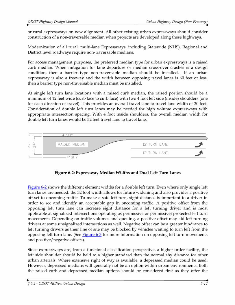
At single left turn lane locations with a raised curb median, the raised portion should be a minimum of 12 feet wide (curb face to curb face) with two 4 foot left side (inside) shoulders (one for each direction of travel). This provides an overall travel lane to travel lane width of 20 feet. Consideration of double left turn lanes may be needed for high volume expressways with appropriate intersection spacing. With 4 foot inside shoulders, the overall median width for double left turn lanes would be 32 feet travel lane to travel lane.
Figure 6-2: Expressway Median Widths and Dual Left Turn Lanes
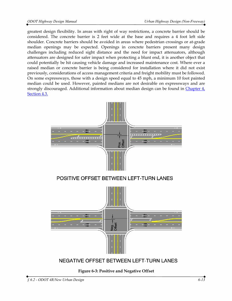
Figure 6-2 shows the different element widths for a double left turn. Even where only single left turn lanes are needed, the 32 foot width allows for future widening and also provides a positive off-set to oncoming traffic. To make a safe left turn, sight distance is important to a driver in order to see and identify an acceptable gap in oncoming traffic. A positive offset from the opposing left turn lane can increase sight distance for a left turning driver and is most applicable at signalized intersections operating as permissive or permissive/protected left turn movements. Depending on traffic volumes and queuing, a positive offset may aid left turning drivers at some unsignalized intersections as well. Negative offset can be a greater hindrance to left turning drivers as their line of site may be blocked by vehicles waiting to turn left from the opposing left turn lane. (See Figure 6-3 for more information on opposing left turn movements and positive/negative offsets).
Since expressways are, from a functional classification perspective, a higher order facility, the left side shoulder should be held to a higher standard than the normal shy distance for other urban arterials. Where extensive right of way is available, a depressed median could be used. However, depressed medians will generally not be an option within urban environments. Both the raised curb and depressed median options should be considered first as they offer the
ODOT Highway Design Manual Urban Highway Design (Non-Freeway)
§ 6.2 - ODOT 4R/New Urban Design 6-13
greatest design flexibility. In areas with right of way restrictions, a concrete barrier should be considered. The concrete barrier is 2 feet wide at the base and requires a 4 foot left side shoulder. Concrete barriers should be avoided in areas where pedestrian crossings or at-grade median openings may be expected. Openings in concrete barriers present many design challenges including reduced sight distance and the need for impact attenuators, although attenuators are designed for safer impact when protecting a blunt end, it is another object that could potentially be hit causing vehicle damage and increased maintenance cost. Where ever a raised median or concrete barrier is being considered for installation where it did not exist previously, considerations of access management criteria and freight mobility must be followed. On some expressways, those with a design speed equal to 45 mph, a minimum 10 foot painted median could be used. However, painted medians are not desirable on expressways and are strongly discouraged. Additional information about median design can be found in Chapter 4, Section 4.3.
Figure 6-3: Positive and Negative Offset
ODOT Highway Design Manual Urban Highway Design (Non-Freeway)
§ 6.2 - ODOT 4R/New Urban Design 6-14
6.2.1.7 LANE WIDTHS
Expressways offer a very high level of mobility and safety. As such lane widths should be held to a high operating standard. All travel lane widths shall be 12 feet on all urban expressways. Where right turn lanes are provided at intersections, they shall be in conformance with Figure 8-8. Left turn lanes shall include a 12 foot lane with a 4 foot traffic separator. For major intersections, dual left turn lanes may be required.
In these instances, the design should follow the recommendations in Figure 8-21. If the traffic separator is a raised curb, a 4 foot shy distance should be provided between the through travel lanes and the curb.
6.2.1.8 INTERSECTIONS AND INTERCHANGES
Connections to expressways can be either at-grade intersections or grade separated interchanges. There are many factors to consider in the design of these types of connections. Urban interchange spacing (crossroad to crossroad) shall follow Table 9-1. For more information relating to expressway intersection design, refer to Chapter 8. For additional information about interchange design for expressways, refer to Chapter 9.
6.2.1.9 DESIGN EXCEPTIONS
As with any urban roadway, right of way constraints, cost, terrain, and other constraints may necessitate designing expressways below the standards described above. The appropriate design exception must be obtained to reduce any design element below standard criteria. Exceptions from expressway design standards must be justified. Due to the mobility needs of expressways, they should be held to a high standard and therefore exceptions should be minimized. For more information on the design exception process, refer to Chapter 14.
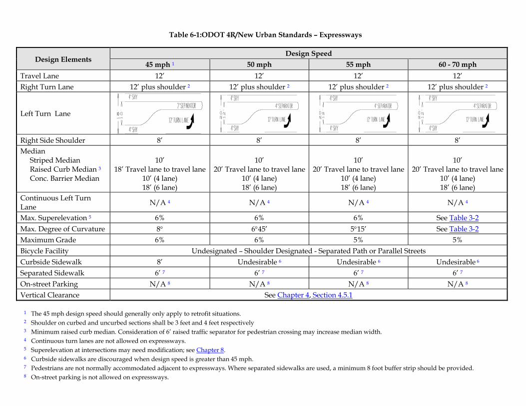
Table 6-1:ODOT 4R/New Urban Standards – Expressways
Design Elements Design Speed
45 mph 1 50 mph 55 mph 60 - 70 mph Travel Lane 12’ 12’ 12’ 12’ Right Turn Lane 12’ plus shoulder 2 12’ plus shoulder 2 12’ plus shoulder 2 12’ plus shoulder 2
Left Turn Lane
Right Side Shoulder 8’ 8’ 8’ 8’ Median
Striped Median Raised Curb Median 3 Conc. Barrier Median
10’
18’ Travel lane to travel lane 10’ (4 lane) 18’ (6 lane)
10’
20’ Travel lane to travel lane 10’ (4 lane) 18’ (6 lane)
10’
20’ Travel lane to travel lane 10’ (4 lane) 18’ (6 lane)
10’
20’ Travel lane to travel lane 10’ (4 lane) 18’ (6 lane)
Continuous Left Turn Lane N/A 4 N/A 4 N/A 4 N/A 4
Max. Superelevation 5 6% 6% 6% See Table 3-2 Max. Degree of Curvature 8° 6°45’ 5°15’ See Table 3-2 Maximum Grade 6% 6% 5% 5% Bicycle Facility Undesignated – Shoulder Designated - Separated Path or Parallel Streets Curbside Sidewalk 8’ Undesirable 6 Undesirable 6 Undesirable 6 Separated Sidewalk 6’ 7 6’ 7 6’ 7 6’ 7 On-street Parking N/A 8 N/A 8 N/A 8 N/A 8 Vertical Clearance See Chapter 4, Section 4.5.1
1 The 45 mph design speed should generally only apply to retrofit situations. 2 Shoulder on curbed and uncurbed sections shall be 3 feet and 4 feet respectively 3 Minimum raised curb median. Consideration of 6’ raised traffic separator for pedestrian crossing may increase median width. 4 Continuous turn lanes are not allowed on expressways. 5 Superelevation at intersections may need modification; see Chapter 8. 6 Curbside sidewalks are discouraged when design speed is greater than 45 mph. 7 Pedestrians are not normally accommodated adjacent to expressways. Where separated sidewalks are used, a minimum 8 foot buffer strip should be provided. 8 On-street parking is not allowed on expressways.
ODOT Highway Design Manual Urban Highway Design (Non-Freeway)
§ 6.2 - ODOT 4R/New Urban Design 6-16
6.2.2 SPECIAL TRANSPORTATION AREAS (STAS)
6.2.2.1 GENERAL DESIGN CONCEPTS
Policy 1B of the Oregon Highway Plan provides a link for highway design in conjunction with the adjacent land use and zoning. The policy defines several specific highway designations that are compatible with and encourage specific land use types. A Special Transportation Area (STA) is one of those highway designation types. STAs are those areas within urban growth boundaries that by their nature are more densely developed and populated. These areas are usually existing downtowns, central business districts, or community centers with lower ADT, lower posted speeds and generally two travel lanes. In some instances, a downtown multi-lane roadway section could meet the intended STA needs and criteria. This is particularly true for multi-lane couplet locations in high density, downtown core areas with appropriate adjacent land uses.
The primary objective of an STA is to provide access to community activities, businesses, and residences, and to accommodate pedestrian, bicycle, and transit movement along and across the highway. Providing and encouraging a well-designed pedestrian, bicycle, and transit friendly environment is a major goal of the designer in these areas. Traffic speeds are slow, usually 25 miles per hour or slower. This generally means that through traffic operations and efficiency may be reduced in order to improve the attractiveness and operations of other modes of travel. Intended STA concepts are best addressed in a narrower cross-section and are not as conducive to multi-lane roadways. Multi-lane roadways with lower volumes and lower speeds may exhibit characteristics and land uses that can benefit from STA concepts. However, multi-lane roadways with higher ADT and higher speed may be better suited to other highway designations that could utilize boulevard treatments to meet increased pedestrian and community needs. STA designations are important for incorporating community and livability along downtown roadway sections. They are an excellent location to utilize context sensitive design and practical design. In order to gain the most benefit from the concepts and characteristics of Special Transportation Areas, STAs should be utilized on roadway sections that reflect the intended attributes listed with the general discussion about Special Transportation Areas in the OHP on pages 49 through 51 and that coordinate with anticipated land uses as discussed in the Policy 1B sections of the OHP.
It may be desirable in some locations to have a roadway segment designated as an STA prior to all of the intended characteristics, attributes or adjacent land uses that define an STA are in place. This can set the stage for development to occur as a community would like to see it happen. In these locations, it is important for the designer to understand the design concepts and balance the need to provide design elements to fit the future development while addressing the needs of the current traffic patterns. It is important to utilize design elements that will encourage the development of the STA, rather than discourage it by using only design criteria that reflects the current environment. This is a difficult task and may require alternative design methods to accomplish it. These locations should be designed on a case-by-case basis in order to achieve the necessary balance of design elements.
ODOT Highway Design Manual Urban Highway Design (Non-Freeway)
§ 6.2 - ODOT 4R/New Urban Design 6-17
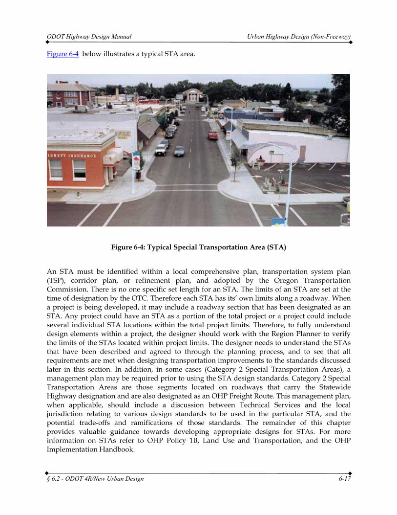
Figure 6-4 below illustrates a typical STA area.
Figure 6-4: Typical Special Transportation Area (STA)
An STA must be identified within a local comprehensive plan, transportation system plan (TSP), corridor plan, or refinement plan, and adopted by the Oregon Transportation Commission. There is no one specific set length for an STA. The limits of an STA are set at the time of designation by the OTC. Therefore each STA has its’ own limits along a roadway. When a project is being developed, it may include a roadway section that has been designated as an STA. Any project could have an STA as a portion of the total project or a project could include several individual STA locations within the total project limits. Therefore, to fully understand design elements within a project, the designer should work with the Region Planner to verify the limits of the STAs located within project limits. The designer needs to understand the STAs that have been described and agreed to through the planning process, and to see that all requirements are met when designing transportation improvements to the standards discussed later in this section. In addition, in some cases (Category 2 Special Transportation Areas), a management plan may be required prior to using the STA design standards. Category 2 Special Transportation Areas are those segments located on roadways that carry the Statewide Highway designation and are also designated as an OHP Freight Route. This management plan, when applicable, should include a discussion between Technical Services and the local jurisdiction relating to various design standards to be used in the particular STA, and the potential trade-offs and ramifications of those standards. The remainder of this chapter provides valuable guidance towards developing appropriate designs for STAs. For more information on STAs refer to OHP Policy 1B, Land Use and Transportation, and the OHP Implementation Handbook.
ODOT Highway Design Manual Urban Highway Design (Non-Freeway)
§ 6.2 - ODOT 4R/New Urban Design 6-18
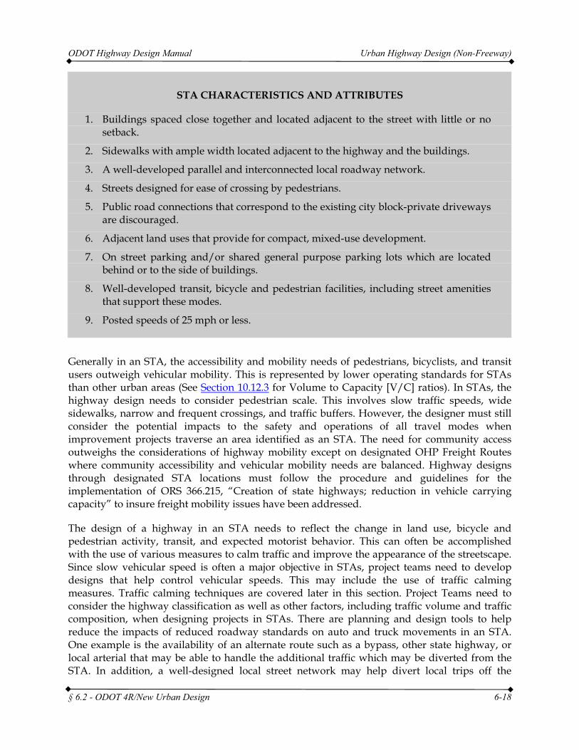
STA CHARACTERISTICS AND ATTRIBUTES
1. Buildings spaced close together and located adjacent to the street with little or no setback.
2. Sidewalks with ample width located adjacent to the highway and the buildings.
3. A well-developed parallel and interconnected local roadway network.
4. Streets designed for ease of crossing by pedestrians.
5. Public road connections that correspond to the existing city block-private driveways are discouraged.
6. Adjacent land uses that provide for compact, mixed-use development.
7. On street parking and/or shared general purpose parking lots which are located behind or to the side of buildings.
8. Well-developed transit, bicycle and pedestrian facilities, including street amenities that support these modes.
9. Posted speeds of 25 mph or less.
Generally in an STA, the accessibility and mobility needs of pedestrians, bicyclists, and transit users outweigh vehicular mobility. This is represented by lower operating standards for STAs than other urban areas (See Section 10.12.3 for Volume to Capacity [V/C] ratios). In STAs, the highway design needs to consider pedestrian scale. This involves slow traffic speeds, wide sidewalks, narrow and frequent crossings, and traffic buffers. However, the designer must still consider the potential impacts to the safety and operations of all travel modes when improvement projects traverse an area identified as an STA. The need for community access outweighs the considerations of highway mobility except on designated OHP Freight Routes where community accessibility and vehicular mobility needs are balanced. Highway designs through designated STA locations must follow the procedure and guidelines for the implementation of ORS 366.215, “Creation of state highways; reduction in vehicle carrying capacity” to insure freight mobility issues have been addressed.
The design of a highway in an STA needs to reflect the change in land use, bicycle and pedestrian activity, transit, and expected motorist behavior. This can often be accomplished with the use of various measures to calm traffic and improve the appearance of the streetscape. Since slow vehicular speed is often a major objective in STAs, project teams need to develop designs that help control vehicular speeds. This may include the use of traffic calming measures. Traffic calming techniques are covered later in this section. Project Teams need to consider the highway classification as well as other factors, including traffic volume and traffic composition, when designing projects in STAs. There are planning and design tools to help reduce the impacts of reduced roadway standards on auto and truck movements in an STA. One example is the availability of an alternate route such as a bypass, other state highway, or local arterial that may be able to handle the additional traffic which may be diverted from the STA. In addition, a well-designed local street network may help divert local trips off the
ODOT Highway Design Manual Urban Highway Design (Non-Freeway)
§ 6.2 - ODOT 4R/New Urban Design 6-19
highway and increase overall system capacity. Another factor is the availability and frequency of transit. A good transit system could reduce the auto commuter traffic not only within the STA, but on the entire highway. These factors as well as the highway classification must be considered when developing designs within STAs.
ODOT 4R/New Urban Design Standards for STAs have been developed to meet the goals and objectives of STAs, such as providing access to community and business activities, accommodating pedestrian and bicycle movement in downtown areas, and prioritizing the attractiveness and livability of downtowns over the through traffic movements. The standards listed in the discussion below and in the STA design criteria matrix, Table 6-2 provide a range of design elements to choose from. Because downtowns vary in nature, not all design elements will be the same. Communities are located in different terrain, vary in culture, vary in traffic volumes and composition, and have different goals and needs. STA designated locations may have some form of a management plan. During the design phase of STAs, the project team should review the STA Management Plan to determine the appropriate design element. The ranges of values should be discussed to determine if the values chosen during the design process are applicable for the specific STA location. The designer, working along with the Project Team should look at each STA independently and apply the STA design standards appropriately. The STA standards provide a range of values to use in design of the roadway typical section, as values for lane width, sidewalk, bike lane/shoulder width, median width, and parking width are variable. The surrounding culture, roadway environment, traffic volume and traffic type all need to be considered in order to select applicable standards for a particular STA.
6.2.2.2 PEDESTRIAN
Providing adequate pedestrian facilities in STAs is critical to the vitality of the area. Ample sidewalks of at least 10 feet should be provided in these areas. Sidewalks wider than 10’ are strongly encouraged. Where right-of-way is constrained, sidewalk width less than the required 10 feet may be found to be acceptable. However, the balance of all needs at the location in question must be considered. Providing sidewalks less than 10 feet in width will compromise the intended pedestrian activity of an STA. Where right of way is available, sidewalks wider than 10 feet will provide additional space for streetscape amenities like café furniture, benches, additional plantings, store front sales areas, signs, etc that will not interfere with pedestrian movement and should be considered. A buffer area of some type is strongly recommended in STAs. This may consist of on-street parking or a buffer strip. Where a buffer strip is used, it should be at least 4 feet wide. However, in most of these areas, a buffer strip will not be used as the sidewalk is typically curb-side. Tree wells, planter boxes, or other amenities provide a buffer area between traffic and pedestrians in these areas. Where amenities are used within the sidewalk area, a minimum clear walking path of 6 feet should be provided. The minimum 10 foot sidewalk can include use of a buffer strip of certain width as long as 6 feet of sidewalk (clear walking path) is maintained. For example, the 10 foot minimum sidewalk width can consist of a 4 foot buffer strip of some type and the 6 foot minimum clear walking path sidewalk. The designer may also want to contact the local agency for short and long term pedestrian needs. STAs should also accommodate transit vehicles. Where transit is expected, bus pullouts and bus stops should conform to the recommendations of Chapter 12, Public
ODOT Highway Design Manual Urban Highway Design (Non-Freeway)
§ 6.2 - ODOT 4R/New Urban Design 6-20
Transportation Guidelines, Section 12.3.
Pedestrians need to have many safe, well-designed crossings. All public road connections should allow crossings of each leg. The use of curb extensions, channelization islands, and median islands can reduce the crossing distances and improve pedestrian visibility and safety. In some situations, the use of mid-block pedestrian crossings may be viable and could enhance the pedestrian mobility and circulation within the STA. The same techniques used at intersections may be beneficial for mid-block crossings. The Traffic-Roadway Section of Technical Services can provide additional guidance for designing and locating safe mid-block pedestrian crossings. Approval by the State Traffic Engineer is needed when altering, modifying or installing traffic control elements including marked pedestrian crossings.
6.2.2.3 SHOULDERS/BIKE LANES
Shoulders are considered to be an integral part of the roadway cross-section in STAs. Shoulders provide an additional buffer area for pedestrians, assist with parking maneuvers, provide safer traffic flow, and provide economic and efficient accommodations for bicycle traffic. Shoulder/bike lanes of 5 feet are used in these areas where right of way permits and installation of the shoulder/bike lane will not reduce the sidewalk width below 10 feet. The standard ODOT shoulder/bike lane width is 6’. However, a shoulder/bike lane width of 5 feet will accommodate bicycle travel and is an acceptable width for STA design. The 5 foot shoulder/bike lane width is also used as the minimum width when bicycle lanes are next to curbs or other roadside barriers. In the built environment, the existing roadway cross-section may be limited by buildings, right-of-way or other constraints. In these sections, it may be difficult to fit all the expected and necessary STA design elements across the design section. However, bicycle access is an important piece to the multi-modal intent of an STA. If room for dedicated, striped bike lanes is limited, there may be other ways to provide bicycle access that meets the intent of STA design. For more information on designing bicycle accommodation in an STA, contact the ODOT Bicycle and Pedestrian Facility Specialist.
The shoulder/bike lane is normally located adjacent to the right side travel lane and provides a buffer to parking or curbs. In locations where the roadway consists of a one-way couplet, the left shoulder shall consist of a 1 foot shy distance (in addition to the travel lane width) based upon an STA design speed of 25-30 mph. For other design speeds on one-way couplets, the left side shy distance shall follow Table 4-2. When the left lane on a one-way couplet is up against raised curb that is not continuous, an additional 1 foot of shy distance should be added.
Bicycle lanes are an economical and efficient method of providing bike accommodation in an urban roadway section and, as such, are listed here as a preferred method. Design and striping guidelines have been established and accepted for their use. That is not to say bike lanes are the only option to provide a bicycle facility. There are other methods available to provide the necessary bicycle accommodation as well. However, their use may require additional approvals from the State Traffic-Roadway Engineer and they may entail additional construction cost or right of way acquisition. These alternative bicycle design options include, but are not limited to, cycle tracks, buffered bike lanes, raised bike lanes and separated multi-use paths. An alternative bicycle facility design may be used if it is determined to be the appropriate method for a specific
ODOT Highway Design Manual Urban Highway Design (Non-Freeway)
§ 6.2 - ODOT 4R/New Urban Design 6-21
project location and any necessary approvals have been granted. The Oregon Bicycle and Pedestrian Design Guide provide additional information regarding many types of bicycle facility design. It has been included as an appendix L to this document and should be consulted when exploring bicycle facility design. Page 1-3 provides a generalized matrix for Urban/Suburban bicycle facility separation recommendations based on speed and traffic volume of the adjacent roadway. Although this matrix is not definitive, it can be utilized as an aid in determining bicycle facility options.
6.2.2.4 PARALLEL PARKING
On-street parking is often a necessary component for maintaining a functioning and economically viable-downtown area. Businesses are generally close to the sidewalk with limited off-street parking opportunities. The decision to include on-street parking in these areas should consider the highway classification and function, availability of parallel roadways, adequacy of side street parking and other parking strategies, safety, and maintaining the economic vitality of the downtown area. Generally, on-street parking should be included with roadway designs for STAs whenever possible. On-street parking also increases the potential for conflict between bicyclists and motor vehicles. Through these areas, bicyclists need room to operate and maneuver for opening car doors, mirrors of motor vehicles, and vehicles exiting parking spaces. Where on-street parking is deemed appropriate, the combined on-street parking and bicycle travel width shall not be less than 12 feet (7 feet for parking and 5 feet for bicycle accommodation). If constraints prohibit parallel parking and a bike lane side-by-side and the posted speed is 25 mph or less, it may be possible to accommodate bicycle travel by sharing the travel lane. See Oregon Bicycle and Pedestrian Design Guide for additional information and the ODOT Traffic Line Manual for shared lane marking criteria.
NOTE: Only parallel parking is allowed on state highways. Any other type requires an exception.
6.2.2.5 DIAGONAL PARKING
Diagonal parking is generally not permitted on state highways and should be avoided. However, communities designated and approved by the OTC as an STA may have situations where diagonal parking may be considered. In addition to traditional head-in diagonal parking, many cities have been experimenting with back-in diagonal parking. In locations where diagonal parking is being considered in general, back-in diagonal parking may also be considered where deemed appropriate. The State Traffic-Roadway Engineer must jointly approve the installation of diagonal parking through the design exception process. In order to receive this approval, the diagonal parking is only allowed in an approved and designated STA.
1. A parking utilization study must be completed documenting the need for additional parking opportunities in the STA. The study should be in compliance with the Institute of Transportation Engineers (ITE) guidelines for parking studies and show an existing utilization factor of 85% or greater.
ODOT Highway Design Manual Urban Highway Design (Non-Freeway)
§ 6.2 - ODOT 4R/New Urban Design 6-22
2. The community must demonstrate that the parking demand can not be met by increasing side street parking opportunities or developing off-street shared parking areas.
3. The highway must have a posted speed of 25 mph or less.
4. The Average Daily Traffic (ADT) on the highway should be less than 6,000 vehicles. On multi-lane couplets, the ADT should be less than 6,000 vehicles per direction.
5. The available right of way must be sufficient to provide standard cross section features. A distance of 33 feet is desirable from the curb line to the centerline stripe of the highway. A minimum 10 foot sidewalk is desirable in STAs. Sidewalk widths should not be reduced below the minimum standard to install diagonal parking.
6. Bike lanes should only be striped where sufficient room exists to allow a shy distance to the bike lane and travel lane.
Diagonal parking should only be installed where the above criteria are met and space is available to accommodate all users, including bicycles. Travel lane, bike lane, and parking widths should not be compromised in order to install diagonal parking. The formal approval process will ensure that the conditions above have been met and documented. The decision to approve diagonal parking should only be made where the diagonal parking is justified, found to be reasonably safe, and does not detract from providing a high level of pedestrian design and accommodation. STAs are meant to be very pedestrian and alternative mode friendly; diagonal parking should not reduce these features.
6.2.2.6 ACCESS MANAGEMENT
Access management goals and objectives should be followed within these types of areas. Access management will help to improve the capacity and safety of vehicular traffic, but will also improve pedestrian safety and mobility. Individual private land access should be discouraged in favor of frequent connections to public roadways that correspond to city block patterns. Streets and acceses are design with a pedestrian orientation for increased pedestrian mobility.
Guidance for access management spacing standards for Special Transportation Areas are contained in Appendix C of the Oregon Highway Plan. For additional information regarding access management, see OAR 734, Division 51.
Generally, the purchase of access rights from adjacent properties is not appropriate for STAs. The best approach for managing access in these areas is through the planning and permits processes.
6.2.2.7 MEDIANS
A median is the area of a roadway or highway that separates opposing directions of travel. Medians can either be traversable or non-traversable. A median can be raised curbed or simply a painted stripe.
ODOT Highway Design Manual Urban Highway Design (Non-Freeway)
§ 6.2 - ODOT 4R/New Urban Design 6-23
The use of medians in STAs may or may not be needed. Medians in STAs are generally only located at spot locations to address left turn needs or specific pedestrian needs, such as a mid-block crossing. A left turn bay should be provided at intersections wherever significant left turning volumes are allowed. However, left turns from a through lane, may be acceptable in some situations. Generally, raised curb medians are not appropriate in STAs, unless they are needed to improve pedestrian crossing opportunities, general mobility, access control or appropriate vegetation treatments. The use of highway medians in these areas should consider the classification of the highway, function of the highway, availability of other routes or parallel roadways, economic vitality of the area, impact to pedestrian crossings and pedestrian mobility, and safety for all travel modes. Median widths should range between 12 - 14 feet (not including required shy distance) depending on the traffic volumes, right of way constraints, and other urban elements for both Continuous Two Way Left Turn Lanes (CTWLTLs) and raised curb medians. CTWLTLs should be avoided and should only be used where several continuous intersections are in need of left turn channelization. An additional shy distance is required where a raised curb median is used. Section 4.3 (Median Design) provides more detailed median design information. Table 4-2 provides the required left side shy distances.
Installation of medians in STAs can impact pedestrian crossings. Where medians are required to maintain acceptable traffic flow and safety, the designer needs to evaluate options that reduce the impact to pedestrian crossing and safety. The width of median used should take into consideration the pedestrians needs as well as the roadway needs. When medians are not needed for turning movements, but are needed for pedestrian crossings, the width of the pedestrian crossing median should be 6 feet and preferably 8 feet. In tightly constrained areas a 4 foot median could be used. However, a standard adult bicycle is on the order of 6 feet in length from front wheel to rear wheel at a minimum – longer if a trailer for pulling young children or cargo is attached. Providing less than a 6 foot median in locations where bicycle traffic is expected to cross the highway may not provide adequate median width should a cyclist need to use the median as a refuge. In areas where recreational paths cross the roadway, median widths may need to accommodate more than the length of a standard 6 foot bicycle. In addition to medians, options may include curb extensions, mid-block crossings, pedestrian refuges, or other treatments. Whether or not medians are used, improved pedestrian crossings should be the goal in urban environments.
Installing a raised median where one has not previously existed may require investigation and determination of its affect on truck traffic that uses the section of roadway. ORS 366.215, Creation of state highways; reduction of vehicle –carrying capacity, states that ODOT may not permanently reduce the vehicle-carrying capacity of an identified freight route when altering, relocating, changing or realigning a state highway unless safety or access consideration require the reduction. If a raised median is proposed to be installed, follow applicable ODOT guidance for determination of reduction of vehicle-carrying capacity and ORS 366.215 compliance. Additional information about median design can be found in Chapter 4, Section 4.3.
6.2.2.8 LANE WIDTHS
Functional class, purpose of the highway, volume and nature of traffic, pedestrian mobility and accessibility goals, and available right of way should determine the width of travel lanes within
ODOT Highway Design Manual Urban Highway Design (Non-Freeway)
§ 6.2 - ODOT 4R/New Urban Design 6-24
STAs. The width of all lanes should be evaluated collectively. Lane widths in STAs will vary from 10 to 12 feet. The 10 foot lane width may be used in highly restricted areas where there is little or no truck traffic. Little or no truck traffic is considered less than 100 (ADT) four axle or larger trucks in the design year. 11 foot lane widths are generally adequate to accommodate medium to high traffic volumes including trucks. A 12 foot lane width is most desirable on major highways carrying large volumes of truck and recreational vehicle traffic and is encouraged where practical. In physically constrained areas in STAs, it may be appropriate to utilize a shared lane for bicycle travel or it may be possible to reconfigure lane widths to provide bike lanes. See Chapter 1 of the Oregon Bicycle and Pedestrian Design Guide. In areas that are not physically constrained or where travel lanes are reconfigured to provide bike lanes and there is additional space across the roadway section, bike lanes can be striped with additional separation from on-street parking or the travel lane. Buffered Bike Lane striping must follow appropriate striping methods. Listed below are the requirements for STA lane widths on the NHS.
1. Minimum lane widths on NHS routes shall be 11 feet
2. On all other non-NHS routes:
• 10 foot minimum lane width is allowed for locations where the design year truck volume (ADT) is less than 100 four axle or larger trucks. However, if bus routes, street car lines or light rail transit facilities exist along the roadway, the designer must evaluate if a 10’ lane will adversely affect these transit operations or safety.
The use of narrower lanes can impact the safety and crash potential in downtown areas. For example, trucks and some recreational vehicles are 10.5 feet wide, mirror to mirror. This vehicle width not only has an impact on travel lane width, but also parking lane width, bicycle accommodation, and pedestrian design. All of the roadway elements need to be taken into consideration when designing STAs.
Where left side travel lanes (one-way couplets) are adjacent to curbs, the appropriate shy distance from Table 4-2 must be added to the standard travel lane width. For design speeds of 25 – 30 mph, the shy distance is 1 foot.
While lane widths less than 12’ may be used in designated STAs, requirements of ORS 366.215, Creation of state highways; reduction of vehicle –carrying capacity, must be satisfied. If design lane widths are proposed to be less than the existing lane widths, follow applicable ODOT guidance for determination of reduction of vehicle-carrying capacity and ORS 366.215 compliance.
6.2.2.9 TRAFFIC CALMING
Traffic Calming is a set of techniques used to reduce vehicular travel speeds and provide for safe and pleasant conditions for motorists, bicyclists, pedestrians, and residents. Listed below are several traffic calming techniques. Each roadway section through an STA is typically unique to itself. The traffic calming elements below may not apply to every situation. Appropriate traffic calming techniques applied to each project should be determined by the Project Team
ODOT Highway Design Manual Urban Highway Design (Non-Freeway)
§ 6.2 - ODOT 4R/New Urban Design 6-25
and project development process. The document, Main Street When a Highway Runs through It: a Handbook for Oregon Communities provides complementary traffic calming information to the Highway Design Manual surrounding STA and other downtown type areas located on State Highways.
A. CURB EXTENSIONS
Curb extensions, also known as “bulb-outs,” are effective tools to reduce the pedestrian crossing distances in areas with on-street parking. Curb extensions also increase pedestrian visibility, help control vehicular speeds, enhance transit, and give a “downtown look” to an urban area. Curb extensions also provide a narrowing or pinch point feel to the roadway at intersections.
The curb extensions still must be designed to accommodate the appropriate design vehicle. However, due to the speed, traffic characteristics, and importance of alternative modes in these areas, the level of accommodation (see Section 8.2.2) of large vehicles should be minimal. However, ORS 366.215, Creation of state highways; reduction of vehicle – carrying capacity, states that ODOT may not permanently reduce the vehicle-carrying capacity of an identified freight route when altering, relocating, changing or realigning a state highway unless safety or access consideration require the reduction. When considering the installation of curb extensions, follow applicable ODOT guidance for determination of reduction of vehicle-carrying capacity and ORS 366.215 compliance. Generally, curb extensions should be constructed to the full width of the on-street parking. However, the curbside lane at the curb extension should be at least 14 feet wide from the left lane line to the curb, excluding the parking width. This width allows for both vehicle and bicycle passage at the curb extension. Each curb extension design is different. The curb extension should not block bicycle lanes and the curb radius should accommodate the necessary design vehicle turning pattern. Multiple radii can be used to form an appropriate overall curb return that accommodates turning vehicles and minimizes pedestrian crossing widths. Figures 12-2 and 12-3 contain several design concepts for consideration. Special consideration is required in many situations for addressing drainage in conjunction with curb extensions, especially in retrofit situations. Elimination of water ponding along the curb extension is critical, particularly in front of sidewalk ramps and bus stop locations.
B. ON-STREET PARKING
Discussed earlier in this section, on-street parking is typically an element of STAs. On-street parking provides friction between the driver and the downtown environment and has potential for reducing speeds. The parked vehicles also provide a buffer between the traffic and pedestrians. An area of concern for designing on-street parking is that it also may reduce the visibility of pedestrians and vehicles approaching or entering the roadway. Also in a narrow cross-section where space is not available to designate a specific bike area, it is more difficult for bicyclists to negotiate the roadway advancing with traffic, while watching for the potential of a driver opening a car door into their path. In an STA, vehicle speed and bicycle speed are more closely matched and utilizing a shared lane condition to provide additional space to parked cars is more appropriate than in other roadway designations.
ODOT Highway Design Manual Urban Highway Design (Non-Freeway)
§ 6.2 - ODOT 4R/New Urban Design 6-26
C. TREES AND LANDSCAPING
Besides providing an STA with a more inviting and visually pleasing effect, landscaping, especially trees, can be a traffic calming technique. Trees provide a vertical element, much in the same way as adjacent buildings, which has an impact on the vehicle driver. A row of trees gives the appearance to the driver that the roadway is narrower and calms traffic. Trees and other landscaping features need to be located in the appropriate location so that sight distance, especially at intersections, is not compromised. Section 4.3.4 provides guidance on the placement of trees in the cross-section.
D. RAISED MEDIANS
As discussed earlier in this section, the need for installing a raised median in an STA should be determined by the Project Team and project development process. The inclusion of a median has multiple traffic calming effects. If wide enough, the median provides a refuge for pedestrians crossing the street. Medians also can be aesthetically pleasing. Medians provide visual narrowing and friction between the median and the motor vehicle driver, which may help in calming traffic speed. If landscaped medians are used, plant and vegitation types used should be low enough so that they do not obstruct visibility. Also, if pedestrian crossing is permissible, they need to be spaced far enough apart to allow for adequate passage. Guidance for the installation of trees in the raised median can be found in Section 4.3.4. Installation of raised medians must be in compliance with ORS 366.215.
E. OTHER TRAFFIC CALMING ELEMENTS
The vertical element is another tool used for traffic calming. Although not part of the roadway design elements, tall buildings adjacent to the highway can help to calm traffic by creating a feeling of enclosure and providing friction between the driver and the downtown environment. Other vertical features that can help to calm traffic include pedestrian scale lighting, hanging baskets, and raised planters.
6.2.2.10 EXCEPTIONS IN STA DESIGNATIONS
Areas within STAs often have very constrained right of way sections due to the existing built environment. Since right of way acquisition is usually difficult, expensive and often undesirable from a historic perspective within these land use areas, it is often minimized or avoided. In addition, project design goals may include elements striving to minimize the pavement cross section to enhance pedestrian circulation and crossing opportunities. Often these types of goals are important elements towards maintaining or improving the sense of place or livability of a community. The design standards listed above should provide the flexibility to accomplish the goals of enhanced pedestrian accommodation and livable communities. Every project is different and should be evaluated on a case by case basis. Each individual project may have a different priority. Any reduction in the design elements given herein will require a design
ODOT Highway Design Manual Urban Highway Design (Non-Freeway)
§ 6.2 - ODOT 4R/New Urban Design 6-27
exception. Table 6-2 lists STA standard design criteria in matrix format for easy review. As previously noted, the design standards for STAs are similar to AASHTO’S “A Policy on Geometric Design of Highways and Streets - 2011” requirements. Reduction in design standards below AASHTO minimums will require substantial documentation and justifications in order to obtain design exceptions.
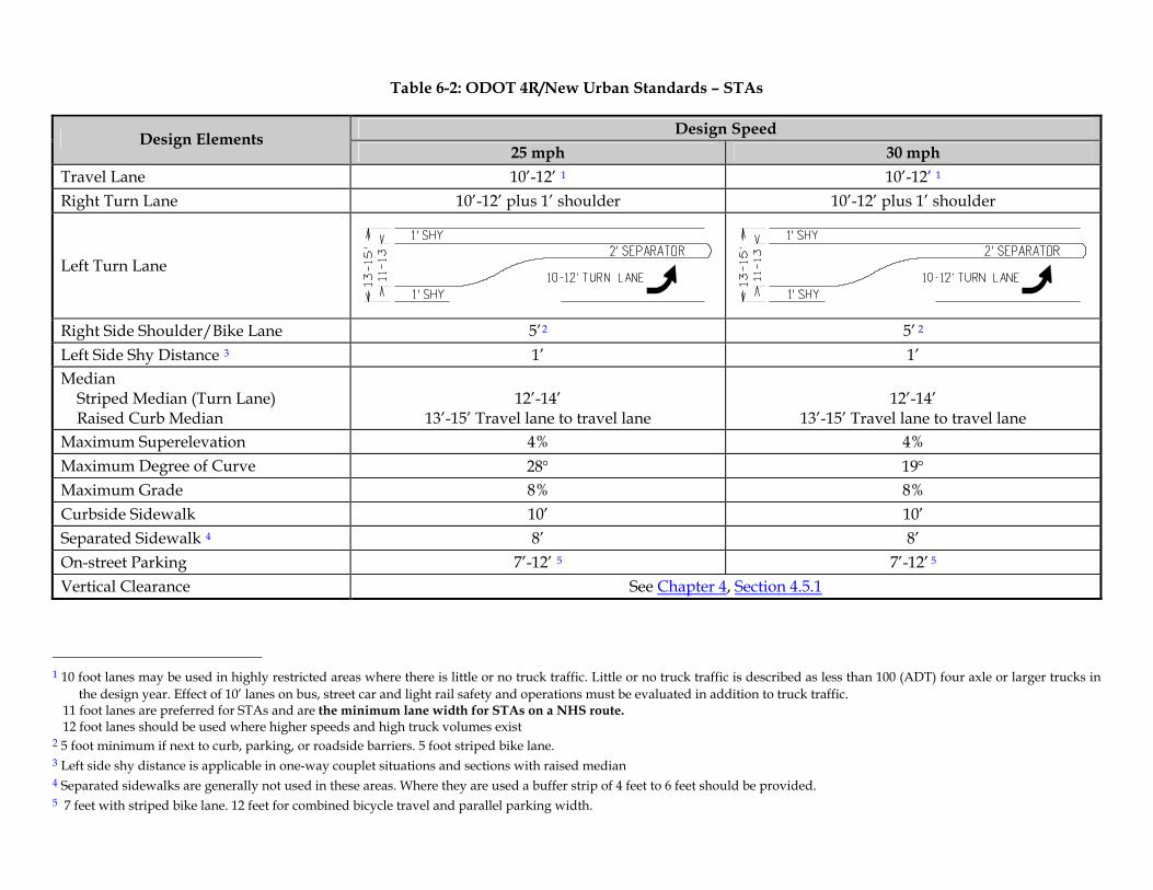
Table 6-2: ODOT 4R/New Urban Standards – STAs
Design Speed Design Elements 25 mph 30 mph
Travel Lane 10’-12’ 1 10’-12’ 1 Right Turn Lane 10’-12’ plus 1’ shoulder 10’-12’ plus 1’ shoulder
Left Turn Lane
Right Side Shoulder/Bike Lane 5’2 5’ 2
Left Side Shy Distance 3 1’ 1’ Median Striped Median (Turn Lane) Raised Curb Median
12’-14’
13’-15’ Travel lane to travel lane
12’-14’
13’-15’ Travel lane to travel lane Maximum Superelevation 4% 4% Maximum Degree of Curve 28° 19° Maximum Grade 8% 8% Curbside Sidewalk 10’ 10’ Separated Sidewalk 4 8’ 8’ On-street Parking 7’-12’ 5 7’-12’ 5
Vertical Clearance See Chapter 4, Section 4.5.1
1 10 foot lanes may be used in highly restricted areas where there is little or no truck traffic. Little or no truck traffic is described as less than 100 (ADT) four axle or larger trucks in
the design year. Effect of 10’ lanes on bus, street car and light rail safety and operations must be evaluated in addition to truck traffic. 11 foot lanes are preferred for STAs and are the minimum lane width for STAs on a NHS route. 12 foot lanes should be used where higher speeds and high truck volumes exist 2 5 foot minimum if next to curb, parking, or roadside barriers. 5 foot striped bike lane. 3 Left side shy distance is applicable in one-way couplet situations and sections with raised median 4 Separated sidewalks are generally not used in these areas. Where they are used a buffer strip of 4 feet to 6 feet should be provided. 5 7 feet with striped bike lane. 12 feet for combined bicycle travel and parallel parking width.
ODOT Highway Design Manual Urban Highway Design (Non-Freeway)
§ 6.2 - ODOT 4R/New Urban Design 6-29
6.2.3 URBAN BUSINESS AREAS (UBAs)
6.2.3.1 GENERAL DESIGN
Urban Business Areas (UBAs) are those areas within urban growth boundaries where commercial activity is located along the highway and where vehicular accessibility is important to economic vitality. UBAs may also be designated where future areas of commercial activity are planned for through a comprehensive plan. UBAs are not permitted on Interstate Highways or Expressways. UBAs may be located on Statewide, Regional, or District level highways with a posted speed greater than 35 mile per hour. The primary objective of the state highway in an UBA is to maintain existing traffic speeds while balancing the access needs of abutting properties with the need to move through traffic. As with STAs, UBAs must also be designated through a corridor plan or local jurisdictional transportation system plan and must be agreed to by both ODOT (OTC) and the local jurisdiction. Figure 6-5 illustrates a potential Urban Business Area.
The UBA highway segment designation is not necessary in areas where posted speeds are 35 miles per hour or less. Highway Design Manual standards for UBAs will be used in areas with posted speeds less than or equal to 35 miles per hour, except where an STA has been designated.
Figure 6-5: Potential Urban Business Area (UBA)
ODOT Highway Design Manual Urban Highway Design (Non-Freeway)
§ 6.2 - ODOT 4R/New Urban Design 6-30
UBA CHARACTERISTICS AND ATTRIBUTES
1. Businesses and buildings clustered in centers or nodes for new development and where possible as redevelopment occurs
2. Consolidated access for new development and where possible as redevelopment occurs.
3. Removal of impediments to inter-parcel circulation
4. Intersections designed to address the needs of pedestrians and bicyclists.
5. Bicycle lanes, sidewalks, crosswalks, or other bicycle/pedestrian accommodations to address safe and accessible pedestrian movement along, across and within the commercial area.
6. Provisions for good traffic progression.
7. Efficient parallel local street system where arterials and collectors connect to the state highway.
8. Provision of transit stops including van/bus stops, transportation demand management or other transit where available.
9. Generally, posted speeds of 35 miles per hour or more. (Highways with posted speed of 35 or less do not need UBA designation to use UBA design criteria, except where an STA has been designated.)
The design focus of a UBA is on designing or redesigning the commercial area so that traffic can circulate within the area rather than having to use the highway to get from place to place. This focus of inter-parcel circulation makes the existing development safer for both the motorist and pedestrian as well as improves the highway mobility. The key to designing a UBA is to maintain existing traffic speeds for through traffic while balancing the needs for accessibility to adjacent properties. Finding the balance of accessibility and mobility is the challenge for the designer on projects within UBAs. Accessibility in this case does not refer to the number of approaches but to the ease and safety of property access. Accessibility can still be obtained with shared approaches, inter-parcel circulation, and local street systems. The other concept in this goal is the term “balance”. Balance does not mean that the level of accessibility must be equal to the amount of mobility. The design of state highways within this land use designation should strive for an appropriate balance of accessibility with inter-community mobility. Therefore, the amount of accessibility is dependent upon the highway classification, speed, roadside culture, and overall system structure. The designer’s role will be to work with the Region Planner and local jurisdiction to use design techniques to maintain existing traffic speeds on the highway while designing for access, traffic progression, and safety features that also ensure the continued economic viability of the area. For more information about UBA segment designations, see the Oregon Highway Plan, Land Use and Transportation and Policy 1B sections.
ODOT Highway Design Manual Urban Highway Design (Non-Freeway)
§ 6.2 - ODOT 4R/New Urban Design 6-31
6.2.3.2 PEDESTRIANS
State highways within this land use area need to accommodate pedestrians on sidewalks. The preferred method is to separate the sidewalk from the highway utilizing a buffer strip. The standard width for sidewalks along state highways is 6 feet, unless the sidewalk is across a bridge. Standard sidewalk width increases to 7 feet on bridges to allow for shy distance to the bridge rail. These standard sidewalk widths are maintained in UBAs. The width of the buffer strip can be varied depending upon the type of landscaping features to be used. Typically, a buffer strip of 3 feet to 6 feet is adequate for most situations. If a buffer strip cannot be provided and the sidewalk is designed curbside, the designer is encouraged to increase sidewalk width to 8 feet in order to provide a more pedestrian friendly environment. When posted speed in a designated UBA is above 35 miles per hour, additional sidewalk width will provide some buffer between pedestrians and higher speed vehicle traffic. When transit vehicles are expected or planned to be using the highway, transit stops should utilize a bus pullout to minimize impact to through traffic. Refer to Chapters 12 and 13 for more information on pedestrian and transit design.
Providing adequate and properly designed pedestrian crossings are a goal in UBAs. At signalized intersections, all crossings should remain open for pedestrian. Raised curb medians should be considered to facilitate mid-block pedestrian crossings. Intersection designs should consider the impacts of turn lanes on pedestrian crossings. The use of channelization islands should be considered to shorten crossing distances.
6.2.3.3 SHOULDERS/BIKE LANES
Shoulders must be provided in these areas. Typically, a shoulder width of 6 feet is adequate for most traffic volume and speed conditions within these areas. As with all shoulders, they are meant to accommodate bicycle traffic as well as provide an operational buffer. Due to the urban nature of these areas, bicycle traffic is expected and therefore should be reasonably accommodated.
The shoulder/bike lane is normally located adjacent to the right side travel lane. In locations where the roadway consists of a one-way couplet, the left shoulder shall consist of a shy distance (in addition to the travel lane width) based upon the UBA’s design speed (see Table 6-3). For other design speeds on one-way couplets, the left side shy distance shall follow Table 4-2. When the left lane on a one-way couplet is up against raised curb that is not continuous, an additional 1 foot of shy distance shall be required.
Bicycle lanes are an economical and efficient method of providing bike accommodation in an urban roadway section and, as such, are listed here as a preferred method. Design and striping guidelines have been established and accepted for their use. That is not to say bike lanes are the only option to provide a bicycle facility. There are other methods available to provide the necessary bicycle accommodation as well. However, their use may require additional approvals from the State Traffic-Roadway Engineer and they may entail additional construction cost or right of way acquisition. These alternative bicycle design options include, but are not limited
ODOT Highway Design Manual Urban Highway Design (Non-Freeway)
§ 6.2 - ODOT 4R/New Urban Design 6-32
to, cycle tracks, buffered bike lanes, raised bike lanes and separated multi-use paths. An alternative bicycle facility design may be used if it is determined to be the appropriate method for a specific project location and any necessary approvals have been granted. The Oregon Bicycle and Pedestrian Design Guide provides additional information regarding many types of bicycle facility design. It has been included as an appendix to this document and should be consulted when exploring bicycle facility design. Page 1-3 provides a generalized matrix for Urban/Suburban bicycle facility separation recommendations based on speed and traffic volume of the adjacent roadway. Although this matrix is not definitive, it can be utilized as an aid in determining bicycle facility options.
6.2.3.4 PARKING
UBAs are not appropriate for on-street parking due to the higher traffic speeds, traffic volumes, and typical development patterns. In most UBAs, buildings are clustered in nodes or centers with limited access to the highway and parking located within the node. These types of businesses and land uses generally would not benefit from on-street parking. A major function of highways within these areas is to provide effective vehicular mobility. On-street parking reduces capacity and efficiency, and may decrease safety in UBAs. Therefore, on-street parking should not be considered on state highways within this land use area.
6.2.3.5 ACCESS MANAGEMENT
Mobility generally is still a high priority in UBAs. As such, access management is an important tool that can help to maintain the mobility and safety of the highway. However, highway mobility is balanced with property access in UBAs. The access management spacing standards are contained in Oregon Administrative Rule, Chapter 734, Division 51. Statewide (NHS) Highways should be held to a higher standard than Regional or District level highways. However, access management is also important for preserving the functionality of Regional and District level highways. The following guidelines should be used if possible when developing access management plans or designs:
1. Priority should be given for connections to public roads over private land access as applicable.
2. Access should be directed to public road connections and/or frontage roads.
3. Private drives, when alternatives do not exist, should be consolidated and shared between multiple properties where practical.
4. Private access points on opposite sides of the highway should be located across from each other where practical, particularly in conjunction with a CTWLTL.
Generally, access rights are not to be purchased from adjacent properties within this land use area. Under some conditions, such as protection around interchange ramp terminals or critical intersections, the purchase of access rights would be justified. For more information on access management objectives, guidelines, and tools refer to Section 2.6. For additional information on
ODOT Highway Design Manual Urban Highway Design (Non-Freeway)
§ 6.2 - ODOT 4R/New Urban Design 6-33
access management and spacing standards, refer to the Access Management Rule, Oregon Administrative Rule (OAR) Chapter 734, Division 51.
6.2.3.6 MEDIANS
All multi-lane state highways within this land use area, regardless of classification, shall use a median treatment. A median is the area of a roadway or highway that separates opposing directions of travel. Medians can either be traversable or non-traversable. A median can have a raised curb or simply be painted stripe. Non-traversable medians are used in UBAs for operational and safety purposes to control traffic movements to and from access points. The preferred type of non-traversable median for a UBA designated highway segment is a raised curb median and shall be designed and constructed for all new multi-lane highways constructed on completely new alignments. In addition, non-traversable medians are recommended and should be considered for:
1. All multi-lane highways with a forecasted volume of 28,000 vehicles a day or greater within the 20-year planning horizon.
2. Modernization of multi-lane highways which are:
(a) Statewide (NHS) Highways;
(b) Regional Highways where design speeds are greater than 45 mph.
3. Modernization or preservation of multi-lane highways with an annual accident rate greater than the average statewide rate for the same classification.
4. Topograph and horizontal or vertical alignment result in inadequate left-turn intersection sight distance and it is impractical to relocate or reconstruct the connecting approach road or impractical to reconstruct the highway in order to provide adequate intersection sight distance.
In UBA designations, a Continuous Two Way Left Turn Lane (CTWLTL) can be used on two-lane highways or any multi-lane highway where a traversable median is deemed appropriate. Even where a CTWLTL is the preferred median choice, consideration of sections of raised curb medians may be appropriate to control turn movements at signalized intersections or to provide pedestrian crossing opportunities. See Section 4.3 and the Oregon Highway Plan, "Policy 3B: Medians for more information on median design and location". Table 4-2 provides the required left side shy distances.
Installation of raised medians in UBAs must be in compliance with ORS 366.215.
6.2.3.7 LANE WIDTHS
Maintaining a high level of safety and mobility is still important in UBAs. Traffic volumes and speeds are generally moderate. Travel lanes need to be designed to move traffic in a safe and reasonably efficient manner. The width of all lanes should be evaluated collectively. Therefore
ODOT Highway Design Manual Urban Highway Design (Non-Freeway)
§ 6.2 - ODOT 4R/New Urban Design 6-34
travel lanes shall be 12 feet for all Statewide (NHS) Highways and those highways identified as Freight Routes either by the OHP or highways pre-approved for WB-67 interstate vehicles size trucks according to Route Map 7. This size truck has a 67 foot wheelbase and is referred to as the interstate size truck. It is the largest single tractor trailer truck allowed on Oregon Highways without a permit. Route Map 7 is color coded and identifies where the interstate truck is allowed without permit. For all other highways the travel lane width shall also be 12 feet unless:
1. The design speed of the highway is 35 mph or less; and
2. Truck volumes in the design year are less than 250 four axle or larger trucks per day.
Highways that meet both of the above thresholds may utilize an 11 foot lane without acquiring an exception. However, where bus, street car or light rail transit systems also utilize the travel lane, consideration must be given to the effects of an 11 foot lane on operations and safety of both the transit system and the highway. An evaluation should be performed to determine if any potential issues could be created by reducing the travel lane width from 12 feet.
6.2.3.8 DESIGN EXCEPTIONS
Due to the built environment in UBAs, project designs often must work within constrained right of way sections or other obstacles that do not allow use of the desired cross section. Since right of way acquisition is often difficult and expensive in these built up environments, it is often necessary to minimize or avoid these purchases during project development. This creates the potential for design exceptions in order to reduce cross-section elements to meet right of way requirements. ODOT’s Practical Design policy can aid in identifying appropriate design flexibility in these locations. When confronted with cross section constraints, the designer should follow the rationale below. Again, the information below is not in any specific order and is intended to provide the designer with a list of design elements that may be considered and evaluated for their feasibility reduction in constrained areas. Those design elements requiring design exceptions are noted.
1. Consideration of reducing the sidewalk width to 5 feet as long as a roadside buffer area is included in the design. This option should be avoided when pedestrian circulation is an identified project goal. Design exception required.
2. Consideration of reducing the shoulder/bike lane to 5 feet. Design exception required.
3. Consideration of reducing or eliminating the roadside buffer area between the curb line and sidewalk. If a minimum 3 foot buffer cannot be achieved, then the sidewalk should be designed as curbside, with a width of 6 feet. This option should be avoided when pedestrian circulation is an identified project goal.
4. Consideration of reducing the median width. If the design incorporates a raised median, the left side shy distance could be reduced. A minimum shy distance of 1 foot shall be used for raised curb medians. If the design includes a Continuous Two Way Left Turn Lane, the width can be reduced to 13 feet. A design exception is required for a 13 foot left turn lane.
ODOT Highway Design Manual Urban Highway Design (Non-Freeway)
§ 6.2 - ODOT 4R/New Urban Design 6-35
5. If the constraint is located at an intersection, reconsider the need for right turn lanes. If right turn lanes are critical to the operation of the intersection, consider reducing the overall turn lane width to 12 feet. Design exception required.
6. Consideration of reducing the travel lane widths. The minimum travel lane width shall be 11 feet on all classifications of highways within this land use area. Design exception required.
7. Use of multiple reduced design elements in the same cross-section should be avoided. When it is necessary to do so, the cumulative effect of all the reduced design elements must be evaluated in the overall relation to safety and operation of the roadway section.
The above priorities are based upon the premise that the major objectives of highways in UBAs are to balance accessibility and mobility while maintaining the safety of all roadway users. Reducing cross section elements from standards is discouraged. The standards reflect the priority of objectives for highways in these areas. Every reasonable attempt should be made to acquire the necessary right of way or mitigate for topographical constraints. If cross section reductions are needed, all reductions will require an exception. Refer to Chapter 14 for more information on the exception process.
NOTE: Some of the above reduction techniques (as noted) require the appropriate Design Exception approval from the State Traffic-Roadway Engineer.
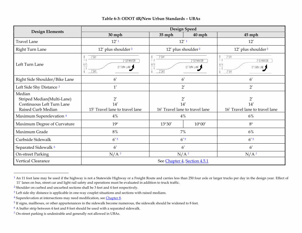
Table 6-3: ODOT 4R/New Urban Standards – UBAs
Design Speed Design Elements 30 mph 35 mph 40 mph 45 mph
Travel Lane 12’ 1 12’ 1 12’
Right Turn Lane 12’ plus shoulder 2 12’ plus shoulder 2 12’ plus shoulder 2
Left Turn Lane
Right Side Shoulder/Bike Lane 6’ 6’ 6’
Left Side Shy Distance 3 1’ 2’ 2’ Median Striped Median(Multi-Lane) Continuous Left Turn Lane Raised Curb Median
2’
14’ 15’ Travel lane to travel lane
2’
14’ 16’ Travel lane to travel lane
2’
14’ 16’ Travel lane to travel lane
Maximum Superelevation 4 4% 4% 6%
Maximum Degree of Curvature 19° 13°30’ 10°00’ 8°
Maximum Grade 8% 7% 6%
Curbside Sidewalk 6’ 5 6’ 5 6’ 5
Separated Sidewalk 6 6’ 6’ 6’ On-street Parking N/A 7 N/A 7 N/A 7 Vertical Clearance See Chapter 4, Section 4.5.1
1 An 11 foot lane may be used if the highway is not a Statewide Highway or a Freight Route and carries less than 250 four axle or larger trucks per day in the design year. Effect of
11’ lanes on bus, street car and light rail safety and operations must be evaluated in addition to truck traffic. 2 Shoulder on curbed and uncurbed sections shall be 3 feet and 4 feet respectively. 3 Left side shy distance is applicable in one-way couplet situations and sections with raised medians. 4 Superelevation at intersections may need modification, see Chapter 8. 5 If signs, mailboxes, or other appurtenances in the sidewalk become numerous, the sidewalk should be widened to 8 feet. 6 A buffer strip between 4 feet and 8 feet should be used with a separated sidewalk. 7 On-street parking is undesirable and generally not allowed in UBAs.
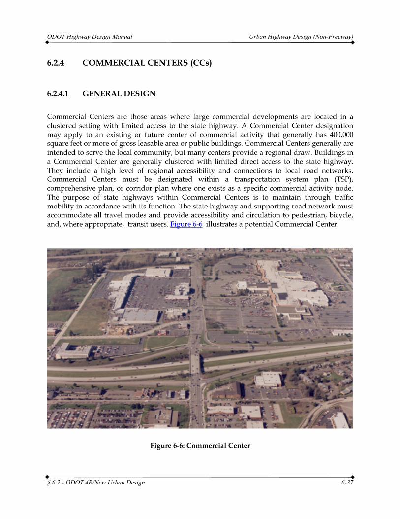
ODOT Highway Design Manual Urban Highway Design (Non-Freeway)
§ 6.2 - ODOT 4R/New Urban Design 6-37
6.2.4 COMMERCIAL CENTERS (CCs)
6.2.4.1 GENERAL DESIGN
Commercial Centers are those areas where large commercial developments are located in a clustered setting with limited access to the state highway. A Commercial Center designation may apply to an existing or future center of commercial activity that generally has 400,000 square feet or more of gross leasable area or public buildings. Commercial Centers generally are intended to serve the local community, but many centers provide a regional draw. Buildings in a Commercial Center are generally clustered with limited direct access to the state highway. They include a high level of regional accessibility and connections to local road networks. Commercial Centers must be designated within a transportation system plan (TSP), comprehensive plan, or corridor plan where one exists as a specific commercial activity node. The purpose of state highways within Commercial Centers is to maintain through traffic mobility in accordance with its function. The state highway and supporting road network must accommodate all travel modes and provide accessibility and circulation to pedestrian, bicycle, and, where appropriate, transit users. Figure 6-6 illustrates a potential Commercial Center.
Figure 6-6: Commercial Center
ODOT Highway Design Manual Urban Highway Design (Non-Freeway)
§ 6.2 - ODOT 4R/New Urban Design 6-38
COMMERCIAL CENTER CHARACTERISTICS AND ATTRIBUTES
1. Clustered, large-scale development with generally 400,000 square feet or more of gross leasable area or public buildings.
2. Commercial or mixed commercial, retail and office activities that may also include multi-family residential and public uses.
3. A high level of regional accessibility.
4. Clustered buildings with consolidated access to the state highway rather than developed along the highway with multiple accesses.
5. The center has convenient internal circulation including provisions for pedestrians and bicyclists. These include bicycle lanes, sidewalks, crosswalks, or other bicycle/pedestrian accommodations to address safe and accessible pedestrian movement along, across and within the commercial center.
6. Provisions of transit stops including van/bus stops, transportation demand management or other transit where available.
7. Connections to the local road network.
Commercial Centers are located within urban growth boundaries on Statewide, Regional or district highways. They can also be located on Expressways where mobility can be maintained as shown through management plans. Since Commercial Centers can be located on a variety of highway designations, there are no specific Highway Design Standards for Commercial Centers. Establishing a single design standard is not practical. The design of state highways around Commercial Centers should be consistent with the classification and function of the highway on which it is located. Speed, traffic volumes, proximity to interchanges, and context of the surrounding area are also important to design criteria in a Commercial Center. Generally these areas should be designed to the standards for either UBAs or for Urban Fringe/Suburban Areas, whichever best describes the surrounding area. If the Commercial Center is adjacent to an interchange, the design should minimize the impacts to the interchange area and the freeway, expressway, or Statewide Highway, and meet the appropriate interchange access management spacing standards as applicable. The spacing standards are contained in OAR Chapter 734, Division 51.
Commercial Centers should be planned and developed to reflect the following characteristics:
1. Convenient circulation within the center, including pedestrian and bicycle access and circulation
2. Provisions for transit access in urban areas planned for fixed route transit service
3. Shared parking and a reduction in parking to accommodate multimodal elements where alternate modes are available
4. A high level of regional accessibility
ODOT Highway Design Manual Urban Highway Design (Non-Freeway)
§ 6.2 - ODOT 4R/New Urban Design 6-39
5. Accessibility by a variety of routes and modes and a local road network so that most of the traffic circulation may occur off the state highway
6. Compact development patterns.
In return for having the above characteristics and adhering strictly to access management spacing standards as provided in OAR Chapter 734, Division 51, the Transportation Commission will consider allowing the highway mobility standard to be the same as that for a Special Transportation Area (STA) at the point of access to the state highway. However, the mobility of any affected freeway interchange may not decline below the highway mobility standard for the interchange designated by Policy 1F (OHP Tables 6 and 7).
6.2.5 OREGON HIGHWAY PLAN SPECIAL OVERLAYS
The OHP describes other special highway designations that must be considered when designing urban highways, including Freight, Lifeline, and Scenic Byway Routes.
6.2.5.1 FREIGHT ROUTE
The Oregon Freight Route system carries a significant tonnage of goods and materials within and through the state. They are shown with the nomenclature of FR in the OHP Highway Classification tables. These routes are to provide a higher level of service and mobility than other statewide highways. However, other state highways serve significant volumes of truck traffic as well and have been pre-approved for use of interstate size trucks. These routes are identified on Route Map 7 that is published by the ODOT Motor Carrier Transportation Division, Over-Dimension Permit Unit. Although Route Map 7 includes all highways, it identifies those highways where the use of interstate size trucks are allowed and should accommodate those vehicles in the design. Route Map 7 can be found at the following web address http://www.odot.state.or.us/forms/motcarr/od/8104.pdf
The OHP Freight Route map is located in Oregon Highway Plan, page 65. Route Map 7 is color coded and identifies where the interstate truck is allowed without permit. Projects on routes identified by either the OHP Freight Map or pre-approved for WB-67 size trucks as shown on Route Map 7 should strongly consider freight needs in the design, particularly intersections. A WB-67 size truck is a single tractor trailer truck with a 67 foot wheelbase; this is currently the largest single tractor trailer approved for travel on Oregon highways without a permit. It is often referred to as the “interstate” design truck. Reducing design standards and through carrying capacity is discouraged on OHP designated Freight Routes. These Freight Routes will generally be the most important facilities to the local jurisdiction as well as surrounding region and possibly the state. As such, they should maintain a high level of functionality. ORS 366.215, Creation of state highways; reduction of vehicle-carrying capacity, states that ODOT may not permanently reduce the vehicle-carrying capacity of an identified freight route when altering, relocating, changing or realigning a state highway unless safety or access consideration require the reduction. When a project is proposed on a designated freight route, follow applicable
ODOT Highway Design Manual Urban Highway Design (Non-Freeway)
§ 6.2 - ODOT 4R/New Urban Design 6-40
ODOT guidance for determination of reduction of vehicle-carrying capacity and ORS 366.215 compliance.
In conjunction with the OHP Freight Route system, the Oregon Highway Plan also recognizes the national truck route network. These routes are federally designated truck routes and are denoted in the OHP with the nomenclature TR for Truck Route in order to differentiate them from the FR used for the Oregon Freight Route system. In many instances, the FR routes and the TR routes are coincident. The FR routes are routes specific to Oregon designation for freight movement within and through the state. Where as, the TR routes are specific to federal designation designed to carry freight effectively from state to state at the national level and are part of the national network of truck routes. TR routes are part of the National Highway System (NHS) and in most cases, when a TR route is located on a state highway that is not designated as part of the FR system, it is still subject to the requirements of ORS 366.215. Projects on these routes must follow the guidelines set out for implementation of ORS 366.215.
A third group of roadways that comprise the freight route system in Oregon are roadways designated as Intermodal Connectors. Intermodal Connectors are part of the National Highway System and connect freight origin and destination points like ports, rail yards or major industrial areas to the arterial highway networks and interstate highways throughout the state. These routes are generally short in length with the majority of them less than a mile long. However, they are of vital importance for freight to get to and from origin and destination points. These roadway segments are located all across the state. A listing of them is included in Appendix E of the Oregon Highway Plan. All of these roadways must meet federal guidelines as part of the NHS. However, not all of these roadways are on state highways. Some of them are part of local jurisdiction networks. Intermodal Connectors located on state highways will need to meet ORS 366.215 requirements and projects on these segments must follow the guidelines set out for implementation of ORS 366.215.
6.2.5.2 LIFELINE ROUTE
Another designation is the Lifeline Route designation. These routes have been identified as critical connections between areas of the state that may become generally inaccessible during an emergency situation such as earthquakes or flooding. It is critical to keep these facilities operating during such disasters to aid evacuation and relief efforts. This designation will generally not have much effect on the design of a particular highway except for structures that are critical to maintaining accessibility.
6.2.5.3 SCENIC BYWAY POLICY
The OHP establishes a Scenic Byway Policy. Scenic Byways have exceptional scenic value to the state. The OTC must designate a route as a Scenic Byway. The intent of the designation is to ensure that the scenic qualities of the highway are preserved and may be enhanced by highway designs and projects. The Scenic Byway designation should not impact the design of urban arterialss. However, the designer should contact the Scenic Byway Program to make sure the

ODOT Highway Design Manual Urban Highway Design (Non-Freeway)
§ 6.2 - ODOT 4R/New Urban Design 6-41
Scenic Byway Corridor Management Plan will not affect the urban highway design. Page 68 of the OHP contains a map of Oregon’s Scenic Byways.
ODOT Highway Design Manual Urban Highway Design (Non-Freeway)
§ 6.3 - Non-Designated Urban Highway 6-42
6.3 NON-DESIGNATED URBAN HIGHWAY
As mentioned earlier, the Oregon Highway Plan established specific designations for urban highway segments that may be used to designate specific types of highways in relation to their adjacent land uses. The specific designations include Expressways, STAs, UBAs, and Commercial Centers. However, not all urban highways can be specifically classified using these designations. Therefore, the Oregon Highway Plan has established the Non-Designated Urban Highway category. As defined by the OHP, Non-Designated Urban Highways (Urban Highways) are those Statewide, Regional or District Highways within urban growth boundaries with posted speed greater than 35 miles per hour that are not otherwise designated or classified as Interstate Highways, Expressways, STAs, UBAs, or Commercial Centers.
The Urban Highway designation applies automatically to urban highway segments not otherwise designated. The objective of a non-designated Urban Highway segment is to efficiently move through traffic while also meeting the access needs of nearby properties. Access can be provided to and from individual properties abutting an Urban Highway segment consistent with permitting criteria set forth in OAR 734-051. Transit turnouts, sidewalks and bicycle lanes are accommodated.
Urban highways traverse many different types of land use areas, from urban fringe and suburban to developed areas and traditional downtowns. In addition, some urban environments will not meet the requirements for receiving the other land use designations, but will still look similar. The designer still needs guidance for dealing with these situations. To help guide design decisions to reflect the appropriate design for a given urban environment along highways, three additional categories are used. Although these categories are mentioned in the Oregon Highway Plan, no specific criteria are found in the OHP. The categories are:
1. Urban Fringe/Suburban
2. Developed
3. Traditional Downtowns/Central Business Districts.
Traditional Downtowns/Central Business Districts are a special case when considering Non-Designated Urban Highways. In many instances, they may have speeds below 35 mph and therefore do not fit the strict OHP definition of Non-Designated Urban Highways, They may look very much like an STA, but are not designated as such. Therefore, they are included in the non-designated section in order to provide guidance to aid designers when they encounter these roadway locations
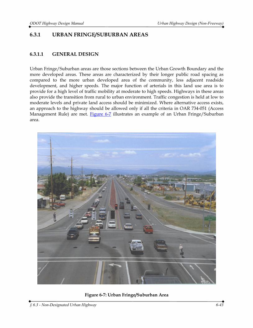
ODOT Highway Design Manual Urban Highway Design (Non-Freeway)
§ 6.3 - Non-Designated Urban Highway 6-43
6.3.1 URBAN FRINGE/SUBURBAN AREAS
6.3.1.1 GENERAL DESIGN
Urban Fringe/Suburban areas are those sections between the Urban Growth Boundary and the more developed areas. These areas are characterized by their longer public road spacing as compared to the more urban developed area of the community, less adjacent roadside development, and higher speeds. The major function of arterials in this land use area is to provide for a high level of traffic mobility at moderate to high speeds. Highways in these areas also provide the transition from rural to urban environment. Traffic congestion is held at low to moderate levels and private land access should be minimized. Where alternative access exists, an approach to the highway should be allowed only if all the criteria in OAR 734-051 (Access Management Rule) are met. Figure 6-7 illustrates an example of an Urban Fringe/Suburban area.
Figure 6-7: Urban Fringe/Suburban Area
ODOT Highway Design Manual Urban Highway Design (Non-Freeway)
§ 6.3 - Non-Designated Urban Highway 6-44
6.3.1.2 PEDESTRIAN
State highways within this land use area need to accommodate pedestrians on sidewalks. The preferred method is to separate the sidewalk from the highway utilizing a buffer area. Sidewalks should be a minimum of 6 feet wide in these areas. The width of the buffer area will be variable depending upon right of way and landscaping needs. Due to the higher traffic speeds found in these locations, the buffer area should be at least 6 feet wide. In locations where a buffer strip cannot be obtained, the designer is encouraged to increase the sidewalk width to 8 feet in order to provide a more pedestrian friendly environment. When transit vehicles are expected or planned to be using the highway, transit stops should utilize a bus pullout to minimize impact to through traffic. For additional information on Pedestrian and Transit Design see Chapters 12 and 13.
Pedestrian accessibility in these areas is often not a major function of the state highway. However, where needed, the design of the highway should still consider opportunities for pedestrians to cross the highway and connecting roadways safely. Signalized intersections should normally have all legs open for pedestrian crossings. Approval by the State Traffic-Roadway Engineer is required to close a crossing. Where feasible, the use of a raised curb median is recommended to facilitate mid-block pedestrian crossings. For additional information about median design see Chapter 4, Section 4.3.
6.3.1.3 SHOULDERS/BIKE LANES
Shoulders significantly improve the safety and operations of urban arterials. Since arterials in urban fringe/suburban areas are to provide a high level of mobility, and safety is a principal goal of any project, paved shoulders are required. Due to the higher speeds associated with these areas, shoulder widths of 6 feet are required. On some higher volume (above 12,000 ADT for two-lane and 28,000 ADT for multi-lane) and higher speed highways (design speed above 45 mph) a shoulder of 8 feet is required.
Shoulders also provide an area for bicycle use. The shoulder in these areas may or may not be striped as a bike lane. In general, when speeds are below 45 mph and the roadway is in a curbed, urban section bike lanes are striped. Regardless, the dimensions above will provide for adequate and safe movement of bicycle traffic.
Bicycle lanes are an economical and efficient method of providing bike accommodation in an urban roadway section and, as such, are listed here as a preferred method. Design and striping guidelines have been established and accepted for their use. That is not to say bike lanes are the only option to provide a bicycle facility. There are other methods available to provide the necessary bicycle accommodation as well. However, their use may require additional approvals from the State Traffic-Roadway Engineer and they may entail additional construction cost or right of way acquisition. These alternative bicycle design options include, but are not limited to, cycle tracks, buffered bike lanes, raised bike lanes and separated multi-use paths. An alternative bicycle facility design may be used if it is determined to be the appropriate method for a specific project location and any necessary approvals have been granted. The Oregon Bicycle and
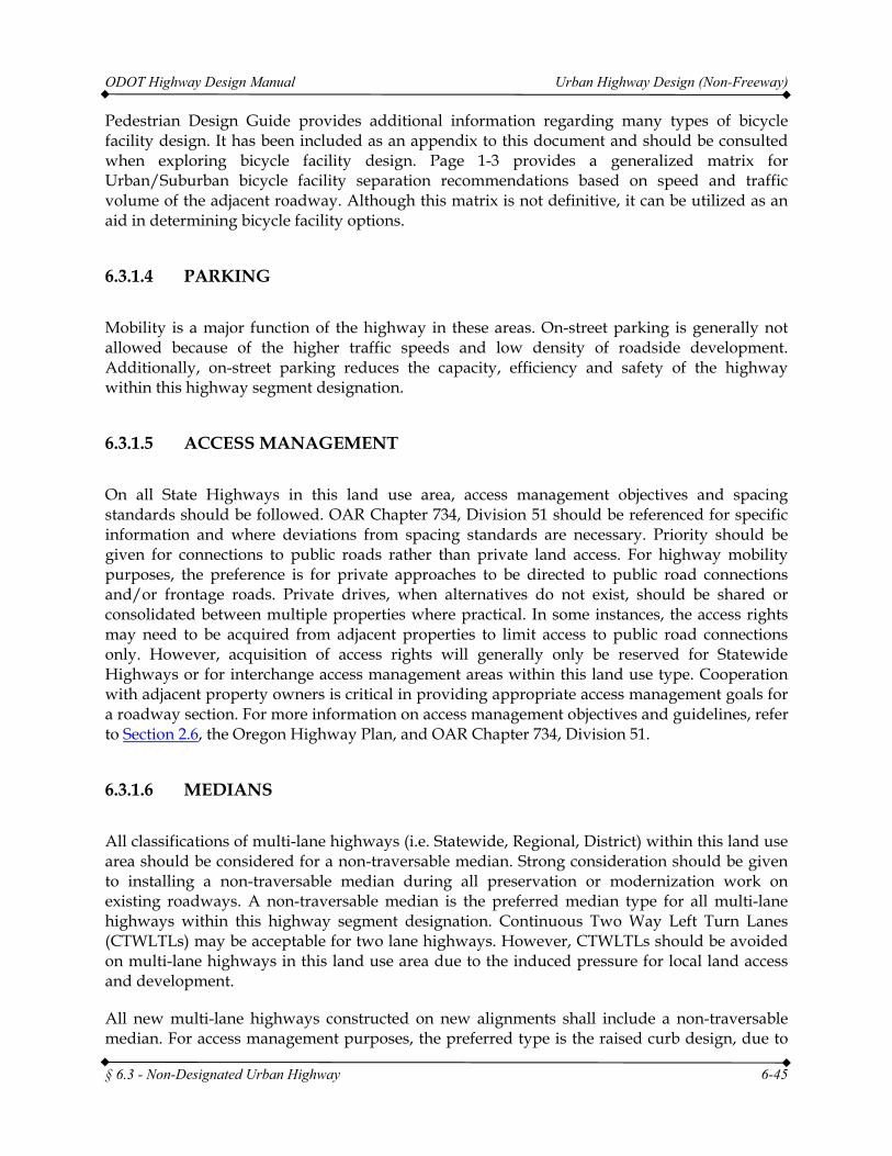
ODOT Highway Design Manual Urban Highway Design (Non-Freeway)
§ 6.3 - Non-Designated Urban Highway 6-45
Pedestrian Design Guide provides additional information regarding many types of bicycle facility design. It has been included as an appendix to this document and should be consulted when exploring bicycle facility design. Page 1-3 provides a generalized matrix for Urban/Suburban bicycle facility separation recommendations based on speed and traffic volume of the adjacent roadway. Although this matrix is not definitive, it can be utilized as an aid in determining bicycle facility options.
6.3.1.4 PARKING
Mobility is a major function of the highway in these areas. On-street parking is generally not allowed because of the higher traffic speeds and low density of roadside development. Additionally, on-street parking reduces the capacity, efficiency and safety of the highway within this highway segment designation.
6.3.1.5 ACCESS MANAGEMENT
On all State Highways in this land use area, access management objectives and spacing standards should be followed. OAR Chapter 734, Division 51 should be referenced for specific information and where deviations from spacing standards are necessary. Priority should be given for connections to public roads rather than private land access. For highway mobility purposes, the preference is for private approaches to be directed to public road connections and/or frontage roads. Private drives, when alternatives do not exist, should be shared or consolidated between multiple properties where practical. In some instances, the access rights may need to be acquired from adjacent properties to limit access to public road connections only. However, acquisition of access rights will generally only be reserved for Statewide Highways or for interchange access management areas within this land use type. Cooperation with adjacent property owners is critical in providing appropriate access management goals for a roadway section. For more information on access management objectives and guidelines, refer to Section 2.6, the Oregon Highway Plan, and OAR Chapter 734, Division 51.
6.3.1.6 MEDIANS
All classifications of multi-lane highways (i.e. Statewide, Regional, District) within this land use area should be considered for a non-traversable median. Strong consideration should be given to installing a non-traversable median during all preservation or modernization work on existing roadways. A non-traversable median is the preferred median type for all multi-lane highways within this highway segment designation. Continuous Two Way Left Turn Lanes (CTWLTLs) may be acceptable for two lane highways. However, CTWLTLs should be avoided on multi-lane highways in this land use area due to the induced pressure for local land access and development.
All new multi-lane highways constructed on new alignments shall include a non-traversable median. For access management purposes, the preferred type is the raised curb design, due to
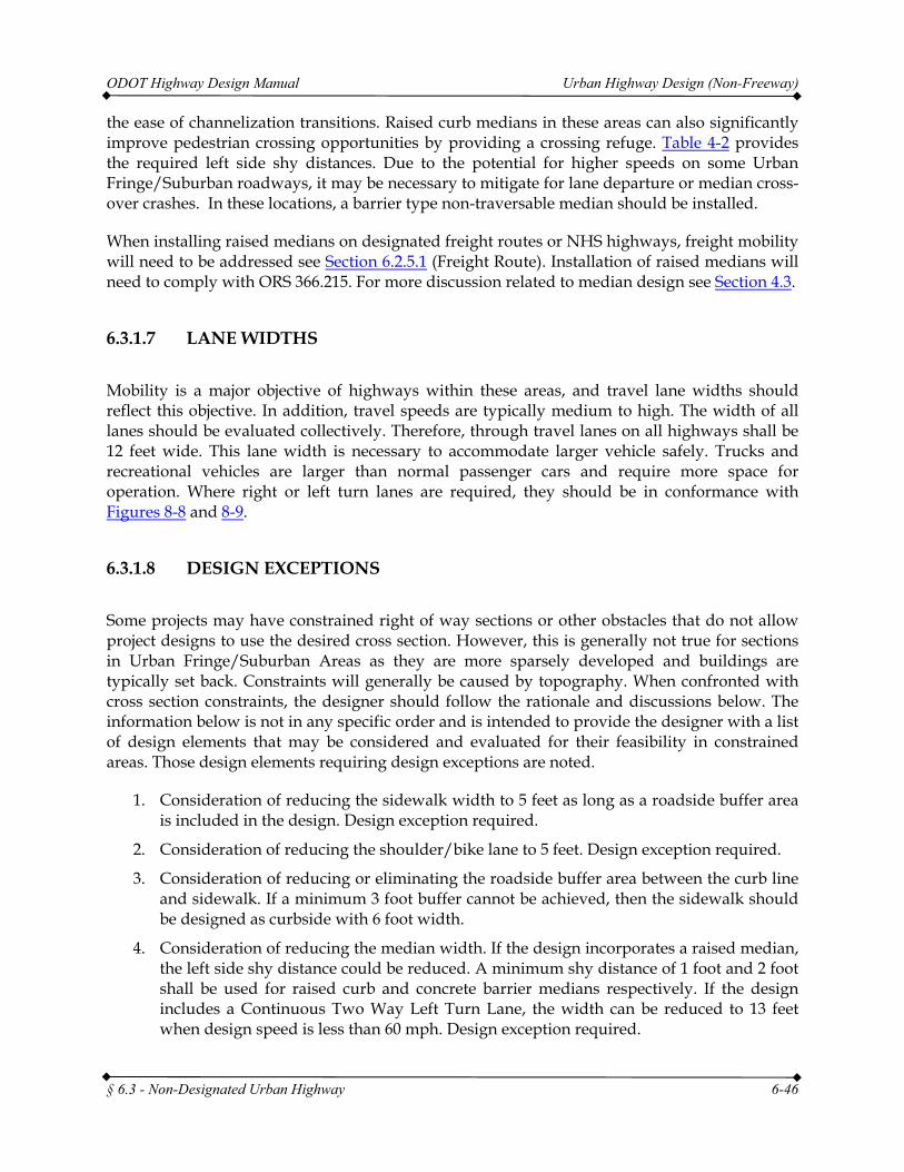
ODOT Highway Design Manual Urban Highway Design (Non-Freeway)
§ 6.3 - Non-Designated Urban Highway 6-46
the ease of channelization transitions. Raised curb medians in these areas can also significantly improve pedestrian crossing opportunities by providing a crossing refuge. Table 4-2 provides the required left side shy distances. Due to the potential for higher speeds on some Urban Fringe/Suburban roadways, it may be necessary to mitigate for lane departure or median cross-over crashes. In these locations, a barrier type non-traversable median should be installed.
When installing raised medians on designated freight routes or NHS highways, freight mobility will need to be addressed see Section 6.2.5.1 (Freight Route). Installation of raised medians will need to comply with ORS 366.215. For more discussion related to median design see Section 4.3.
6.3.1.7 LANE WIDTHS
Mobility is a major objective of highways within these areas, and travel lane widths should reflect this objective. In addition, travel speeds are typically medium to high. The width of all lanes should be evaluated collectively. Therefore, through travel lanes on all highways shall be 12 feet wide. This lane width is necessary to accommodate larger vehicle safely. Trucks and recreational vehicles are larger than normal passenger cars and require more space for operation. Where right or left turn lanes are required, they should be in conformance with Figures 8-8 and 8-9.
6.3.1.8 DESIGN EXCEPTIONS
Some projects may have constrained right of way sections or other obstacles that do not allow project designs to use the desired cross section. However, this is generally not true for sections in Urban Fringe/Suburban Areas as they are more sparsely developed and buildings are typically set back. Constraints will generally be caused by topography. When confronted with cross section constraints, the designer should follow the rationale and discussions below. The information below is not in any specific order and is intended to provide the designer with a list of design elements that may be considered and evaluated for their feasibility in constrained areas. Those design elements requiring design exceptions are noted.
1. Consideration of reducing the sidewalk width to 5 feet as long as a roadside buffer area is included in the design. Design exception required.
2. Consideration of reducing the shoulder/bike lane to 5 feet. Design exception required.
3. Consideration of reducing or eliminating the roadside buffer area between the curb line and sidewalk. If a minimum 3 foot buffer cannot be achieved, then the sidewalk should be designed as curbside with 6 foot width.
4. Consideration of reducing the median width. If the design incorporates a raised median, the left side shy distance could be reduced. A minimum shy distance of 1 foot and 2 foot shall be used for raised curb and concrete barrier medians respectively. If the design includes a Continuous Two Way Left Turn Lane, the width can be reduced to 13 feet when design speed is less than 60 mph. Design exception required.
ODOT Highway Design Manual Urban Highway Design (Non-Freeway)
§ 6.3 - Non-Designated Urban Highway 6-47
5. If the constraint is located at an intersection, reconsider the need for right turn lanes. If right turn lanes are critical to the operation of the intersection, consider reducing the right turn lane to 13 feet (12 foot lane width and 1 foot shoulder width/shy distance). Design exception required.
6. Consideration of reducing the travel lane widths. The minimum travel lane width shall be 11 feet on all classifications of highways within this land use area. Design exception required. In addition to design exception approval, freight mobility concerns will need to be addressed. This is particularly true when lane width reduction will take place on a designated freight route or NHS highway. In addition to freight mobility considerations, if bus, street car or light rail transit facilities are utilizing travel lanes, effects of 11’ lanes on safety and operation of these transit facilities must be evaluated.
7. Use of multiple reduced design elements in the same cross-section should be avoided. When it is necessary to do so, the cumulative effect of all the reduced design elements must be evaluated in the overall relation to safety and operation of the roadway section.
The considerations listed above are based upon the premise that the major objectives of highways in Urban Fringe/Suburban Areas are the safety and mobility of traffic. Reducing cross section elements from standards is discouraged. The standards reflect the priority of objectives for highways in these areas. Every reasonable attempt should be made to acquire the necessary right of way or mitigate for topographical constraints. If cross section reductions are needed, all reductions will require an exception. Refer to Chapter 14 for more information on the exception process.
NOTE: Some of the above reduction techniques (as noted) require the appropriate Design Exception approval from the State Traffic-Roadway Engineer.
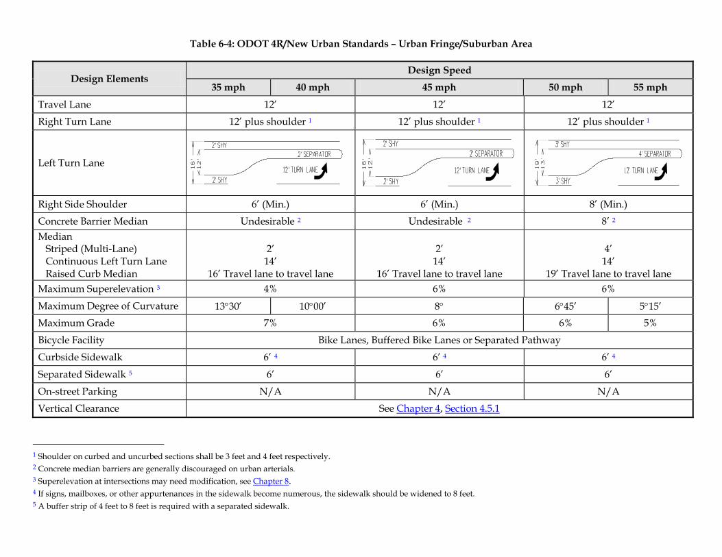
Table 6-4: ODOT 4R/New Urban Standards – Urban Fringe/Suburban Area
Design Elements Design Speed
35 mph 40 mph 45 mph 50 mph 55 mph
Travel Lane 12’ 12’ 12’
Right Turn Lane 12’ plus shoulder 1 12’ plus shoulder 1 12’ plus shoulder 1
Left Turn Lane
Right Side Shoulder 6’ (Min.) 6’ (Min.) 8’ (Min.)
Concrete Barrier Median Undesirable 2 Undesirable 2 8’ 2 Median Striped (Multi-Lane) Continuous Left Turn Lane Raised Curb Median
2’
14’ 16’ Travel lane to travel lane
2’
14’ 16’ Travel lane to travel lane
4’
14’ 19’ Travel lane to travel lane
Maximum Superelevation 3 4% 6% 6%
Maximum Degree of Curvature 13°30’ 10°00’ 8° 6°45’ 5°15’ Maximum Grade 7% 6% 6% 5%
Bicycle Facility Bike Lanes, Buffered Bike Lanes or Separated Pathway
Curbside Sidewalk 6’ 4 6’ 4 6’ 4
Separated Sidewalk 5 6’ 6’ 6’
On-street Parking N/A N/A N/A
Vertical Clearance See Chapter 4, Section 4.5.1
1 Shoulder on curbed and uncurbed sections shall be 3 feet and 4 feet respectively. 2 Concrete median barriers are generally discouraged on urban arterials. 3 Superelevation at intersections may need modification, see Chapter 8. 4 If signs, mailboxes, or other appurtenances in the sidewalk become numerous, the sidewalk should be widened to 8 feet. 5 A buffer strip of 4 feet to 8 feet is required with a separated sidewalk.
ODOT Highway Design Manual Urban Highway Design (Non-Freeway)
§ 6.3 - Non-Designated Urban Highway 6-49
6.3.2 DEVELOPED AREAS
6.3.2.1 GENERAL DESIGN
Developed areas are those areas where most of the adjacent roadside is developed at urban intensities and only a few parcels are vacant. These areas are sometimes referred to as ‘strip development’ areas, but may also include a mixture of industrial/warehouse and residential uses. Typical through traffic speeds are slow to moderate where land uses are intense or moderate. Where land uses are less intense, speeds are often higher. These areas are very similar in nature to Urban Business Areas (UBAs) discussed earlier in this chapter, but do not meet the criteria and intent of a UBA. Mobility of traffic is generally more important in these areas than property access. The amount of accessibility is dependent upon the highway classification, speed, roadside culture, and overall system structure.
6.3.2.2 ODOT 4R/NEW URBAN DESIGN STANDARDS – DEVELOPED AREAS
Generally, the design of state highways in this area should follow the standards and guidelines for UBAs. However, the access management standards for Developed areas are different than UBAs. Developed areas that are not designated as UBAs must adhere to the “Urban Other” standard for the appropriate highway classification. The access management standards are contained in Appendix C of the Oregon Highway Plan. For additional information regarding access management, see OAR 734, Division 51.
6.3.3 TRADITIONAL DOWNTOWN/CENTRAL BUSINESS DISTRICT
6.3.3.1 GENERAL DESIGN
Traditional Downtown/Central Business District areas are densely urbanized areas generally characterized by closely spaced buildings fronting sidewalks, shared or on-street parking, and lower traffic speeds typically around 25 mph to 30 mph. Maintaining traffic mobility is still important in these areas, but accessibility for other modes, especially pedestrians, is also important. These areas may look very similar to Special Transportation Areas (STAs) discussed earlier in this chapter, but do not meet the criteria and intent of an STA or have not been designated as an STA by the Oregon Transportation Commission.
6.3.3.2 PEDESTRIAN
Providing adequate pedestrian facilities in these areas is critical to the vitality of the area.
ODOT Highway Design Manual Urban Highway Design (Non-Freeway)
§ 6.3 - Non-Designated Urban Highway 6-50
Ample sidewalks of at least 10 feet or more should be provided in these areas. Where right of way is available, wider sidewalks should be considered. A buffer area is strongly recommended. This may consist of on-street parking or a buffer strip. Where a buffer strip is used, it should be at least 4 feet wide. However, in most of these areas, a buffer strip may not be used as the sidewalk is typically curb-side. However, tree wells, planter boxes, or other amenities do provide a buffer area between traffic and pedestrians in these areas and are recommended. Where amenities are used within the sidewalk area, a minimum clear walking path of 8 feet should be provided. Many of these areas will also accommodate transit vehicles. Where transit is expected, bus pullouts and bus stops should conform to the recommendations of Sections 12.2 and 12.3 of the HDM.
Pedestrians need to have many safe, well-designed crossings. All public road connections should allow crossings of each leg. The use of curb extensions, channelization islands, and median islands can reduce the crossing distances and improve pedestrian visibility and safety. In some situations, the use of mid-block pedestrian crossings may be viable and could enhance the pedestrian mobility and circulation within the downtown area. The same techniques used at intersections to facilitate pedestrian crossings may be beneficial for mid-block crossings as well. The Technical Services Traffic-Roadway Section can provide additional guidance for designing and locating safe mid-block pedestrian crossings.
6.3.3.3 SHOULDERS/BIKE LANES
Shoulders are an integral piece of the cross-section in these areas. The shoulders help provide additional buffer area for pedestrians, assist with parking maneuvers, provide safer traffic flow, and provide economic and efficient accommodations for bicycle traffic. The ODOT standard shoulder width is 6 feet. The minimum shoulder/bike lane width is 5 feet. In constrained sections within these areas and where right of way permits, the minimum shoulder/bike lane width may be used with approval. Installation of the minimum shoulder/bike lane may not reduce the sidewalk width below 10 feet.
The shoulder/bike lane is normally located adjacent to the right side travel lane. In locations where the roadway consists of a one-way couplet, the left shoulder shall consist of a 1 foot shy distance (in addition to the travel lane width) based upon a design speed of 25-30 mph. For other design speeds on one-way couplets, the left side shy distance shall follow Table 4-2. When the left lane on a one-way couplet is up against raised curb that is not continuous, an additional 1 foot of shy distance shall be required.
Bicycle lanes are an economical and efficient method of providing bike accommodation in an urban roadway section and, as such, are listed here as a preferred method. Design and striping guidelines have been established and accepted for their use. That is not to say bike lanes are the only option to provide a bicycle facility. There are other methods available to provide the necessary bicycle accommodation as well. However, their use may require additional approvals from the State Traffic-Roadway Engineer and they may entail additional construction cost or right of way acquisition. These alternative bicycle design options include, but are not limited to, cycle tracks, buffered bike lanes, raised bike lanes and separated multi-use paths. An alternative bicycle facility design may be used if it is determined to be the appropriate method
ODOT Highway Design Manual Urban Highway Design (Non-Freeway)
§ 6.3 - Non-Designated Urban Highway 6-51
for a specific project location and any necessary approvals have been granted. The Oregon Bicycle and Pedestrian Design Guide provides additional information regarding many types of bicycle facility design. It has been included as an Appendix L to this document and should be consulted when exploring bicycle facility design. Page 1-3 provides a generalized matrix for Urban/Suburban bicycle facility separation recommendations based on speed and traffic volume of the adjacent roadway. Although this matrix is not definitive, it can be utilized as an aid in determining bicycle facility options.
6.3.3.4 PARKING
Generally, on-street parking should be included with roadway designs for these types of areas whenever possible. On-street parking is often a necessary component for maintaining a functioning and economically viable downtown area. Businesses are generally close to the sidewalk with limited off-street parking opportunities. The decision to include on-street parking in these areas should consider the highway classification and function, availability of parallel roadways, adequacy of side street parking and other parking strategies, safety, and maintaining the economic vitality of the downtown area. On-street parking increases the potential for conflict between bicyclists and motor vehicles. Through these areas, bicyclists need room to operate and maneuver for opening car doors, mirrors of motor vehicles, and vehicles exiting parking spaces. The combined on-street parking and bicycle travel width shall be at least 12 feet. At this minimal total width, depending on how the parking width and bike travel width is divided, a design exception may be necessary.
NOTE: Only parallel parking is allowed on state highways. Any other type requires an exception.
6.3.3.5 ACCESS MANAGEMENT
Traditional Downtowns/Central Business Districts that have not received the STA designation must meet appropriate access management spacing criteria of the Oregon Highway Plan. However, since the block spacing typically associated with these types of areas is almost always less than the standard spacing, it means all new requests may require a deviation. New private approaches within these areas should be discouraged in favor of orienting accesses with public road connections that correspond with the city street network. New public roadway connections should be carefully evaluated to determine the safety, capacity, and operational impacts to the state highway system. New connections should not be allowed unless the analysis clearly shows the new connection will not significantly degrade the safety, capacity, and operation of the state highway. For specific information regarding access management, see OAR 734, Division 51.
6.3.3.6 MEDIANS
The use of medians may or may not be needed. A median is often needed to adequately handle
ODOT Highway Design Manual Urban Highway Design (Non-Freeway)
§ 6.3 - Non-Designated Urban Highway 6-52
left turning traffic. A left turn bay should be provided at intersections wherever significant left turning volumes are allowed. However, left turns from a through lane, especially within multi-lane sections, may be acceptable in some situations. Generally, raised curb medians are not appropriate in these areas, unless they are needed to improve pedestrian crossing opportunities and general mobility. The use of highway medians in these areas should consider the classification of the highway, function of the highway, availability of other routes or parallel roadways, economic vitality of the area, impact to pedestrian crossings and pedestrian mobility, and safety for all travel modes. Median widths shall be 14 feet for both Continuous Two Way Left Turn Lanes and raised curb medians. An additional shy distance is required where a raised curb median is used. Section 4.3 provides more detailed median design information. Table 4-2 provides the required left side shy distances. In addition to the above considerations, when installing raised medians on designated freight routes or NHS highways, freight mobility will need to be addressed and requirements of ORS 366.215 must be met.
Installation of medians in downtowns and CBDs can impact pedestrian crossings. Where medians are required to maintain acceptable traffic flow and safety, the designer needs to evaluate options that reduce the impact to pedestrian crossing and safety. The width of median used should take into consideration the pedestrians needs as well as the roadway needs. When medians are not needed for turning movements, but are needed for pedestrian crossings, the width of the pedestrian crossing median should be 6 feet and preferably 8 feet. In tightly constrained areas a 4 foot median could be used. However, a standard adult bicycle is on the order of 6 feet in length from front wheel to rear wheel at a minimum – longer if a trailer for pulling young children or cargo is attached. Providing less than a 6 foot median in locations where bicycle traffic is expected to cross the highway may not provide adequate median width should a cyclist need to use the median as a refuge. In areas where recreational paths cross the roadway, median widths may need to accommodate more than the length of a standard 6 foot bicycle. In addition to medians, options may include curb extensions, mid-block crossings, pedestrian refuges, or other treatments. Whether or not medians are used, improved pedestrian crossings should be the goal in urban environments.
Installing a raised median where one has not previously existed may require investigation and determination of its affect on truck traffic that uses the section of roadway. ORS 366.215, Creation of state highways; reduction of vehicle –carrying capacity, states that ODOT may not permanently reduce the vehicle-carrying capacity of an identified freight route when altering, relocating, changing or realigning a state highway unless safety or access consideration require the reduction. If a raised median is proposed to be installed, follow applicable ODOT guidance for determination of reduction of vehicle-carrying capacity and ORS 366.215 compliance. Additional information about median design can be found in Chapter 4, Section 4.3.
6.3.3.7 LANE WIDTHS
The standard lane width for these areas is 12 feet. However, an 11 foot lane may be used in these areas without an exception if all the following conditions are met:
1. The highway is not an NHS or OHP Freight Route; and
ODOT Highway Design Manual Urban Highway Design (Non-Freeway)
§ 6.3 - Non-Designated Urban Highway 6-53
2. Design speed of the highway is 30 mph or less; and
3. The highway section carries less than 250 four-axle or larger trucks per day in the design year.
Even when all of the above conditions have been met, if existing lane widths will be reduced during construction or after a project is completed, consult ODOT Motor Carrier to determine freight mobility issues or impacts and compliance with ORS 366.215.
All other conditions require an exception for reductions from the 12 foot standard. Where bus, street car or light rail transit systems also utilize the travel lane, consideration must be given to the effects of an 11 foot lane on operations and safety of both the transit system and the highway. An evaluation should be performed to determine if any potential issues could be created by reducing the travel lane width from 12 feet. Generally, lane widths should not be allowed below 11 feet even through the exception process.
6.3.3.8 MOBILITY STANDARDS
The final element that distinguishes these areas from STAs are the mobility standards. Traditional Downtowns/Central Business Districts that are not designated as STAs must adhere to the appropriate mobility standard contained in Section 10.12
6.3.3.9 TRAFFIC CALMING
Traffic calming is a set of techniques which are used to reduce vehicular travel speeds and provide for safe and pleasant conditions for motorists, bicyclists, pedestrians, and residents. These traffic calming methods are the same treatments mentioned in the STA design section. The document, Main Street… When a Highway Runs Through It: A Handbook for Oregon Communities provides complementary information to the Highway Design Manual surrounding downtown areas and State Highways. Not all traffic calming techniques will be appropriate for state highways. When considering the use of traffic calming elements, contact the Technical Services Roadway Section for guidance.
6.3.3.10 DESIGN EXCEPTIONS
Areas within traditional downtowns/CBDs often have very constrained right of way sections due to the built existing environment. Since right of way acquisition is usually difficult, expensive and often undesirable from a historic perspective within these land use areas, it is often minimized or avoided. In addition, project design goals may include elements striving to minimize the pavement cross section to enhance pedestrian circulation and crossing opportunities. Often these types of goals are important elements towards maintaining or improving the sense of place or livability of a community. The design standards should provide the flexibility to accomplish the goals of enhanced pedestrian accommodation and livable
ODOT Highway Design Manual Urban Highway Design (Non-Freeway)
§ 6.3 - Non-Designated Urban Highway 6-54
communities.
When confronted with cross section constraints, the designer should follow the rationale below. The information below is not in any specific order within the major categories and is intended to provide the designer with a list of design elements that may be considered and evaluated for their feasibility in constrained areas. Any reduction in the following design elements from those standards given above will require a design exception where noted.
1. First:
(a) Consideration of reducing the shoulder/bicycle lane to 4 feet. Design exception required.
(b) Consideration of reducing the combined on-street parking and bicycle lane width to 11 feet. Design exception required.
(c) Consideration of reducing the median width. If the design incorporates a raised median, the left side shy distance could be reduced. A minimum shy distance of 1 foot shall be used for raised curb medians. If the design includes a Continuous Two Way Left Turn Lane the width can be reduced to 13 feet. Design exception required.
(d) Consideration of reducing the sidewalk width. If the design originally proposed very wide sidewalks (greater than 10 feet) consider reducing sidewalk width to 10 feet.
(e) Consideration of reducing the through travel lanes. Reduce travel lane widths to 11 feet. Design exception required when not meeting criteria for 11 foot lane usage. Also, freight mobility impacts will need to be addressed, (ORS 366.215).
2. Second:
(a) Consideration of reducing the width of the sidewalk to 9 feet.
(b) Consideration of eliminating on-street parking on one or both sides.
(c) Consideration of eliminating left turn lanes. The median width could be reduced significantly, if appropriate. On multilane sections, a minimum 2 foot striped median should be included to provide some separation of traffic. Where left turn lanes are needed, consider reducing the median width to 12 feet. Design exception required.
3. Third:
(a) Consideration of reducing the sidewalk width to 8 feet. In addition, the through travel lanes may be reduced to 10 feet when:
• Design speed is 25 mph or less, and • Truck traffic is routed to alternative roadways and truck traffic in the area is
limited to 250 four-axle trucks or larger per day providing only localized service. Design exception required.
(b) Other considerations:
• If the constraint is at an intersection, reconsider the need for right turn lanes. If right turn lanes are critical to the operation of the intersection, consider reducing the turn lane width to 12 feet. Requires design exception.

ODOT Highway Design Manual Urban Highway Design (Non-Freeway)
§ 6.3 - Non-Designated Urban Highway 6-55
• If the constraint is at an intersection, consider eliminating parking at the intersection to obtain the necessary width to accommodate the needed lanes.
• A localized constraint should not be used to dictate the full project design.
The above priorities for Traditional Downtowns/CBDs attempt to hold pedestrian mobility to a higher standard while balancing the mobility and safety needs of other users. Reducing cross section elements from standards is discouraged. The standards reflect engineering best practices for highways in these areas. Every attempt should be made to acquire the necessary right of way or mitigate for topographical constraints. If cross section reductions are needed, they will require an exception. Refer to Chapter 14 for more information on the exception process.
NOTE: Some of the above reduction techniques (as noted) require the appropriate Design Exception approval from the State Traffic-Roadway Engineer during either project development or approval and adoption of an STA Management Plan in accordance with the OHP Implementation Handbook.
Use of multiple reduced design elements in the same cross-section should be avoided. When it is necessary to do so, the cumulative effect of all the reduced design elements must be evaluated in the overall relation to safety and operation of the roadway section
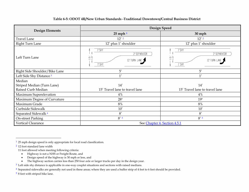
Table 6-5: ODOT 4R/New Urban Standards -Traditional Downtown/Central Business District
Design Speed Design Elements
25 mph 1 30 mph Travel Lane 12’ 2 12’ 2 Right Turn Lane 12’ plus 1’ shoulder 12’ plus 1’ shoulder
Left Turn Lane
Right Side Shoulder/Bike Lane 5’ 5’ Left Side Shy Distance 3 1’ 1’ Median Striped Median (Turn Lane) Raised Curb Median
14’
15’ Travel lane to travel lane
14’
15’ Travel lane to travel lane Maximum Superelevation 4% 4% Maximum Degree of Curvature 28° 19° Maximum Grade 8% 8% Curbside Sidewalk 10’ 10’ Separated Sidewalk 4 8’ 8’ On-street Parking 8’ 5 8’ 5 Vertical Clearance See Chapter 4, Section 4.5.1
1 25 mph design speed is only appropriate for local road classification. 2 12 foot standard lane width 11 foot allowed when meeting following criteria:
• Highway is not a NHS or Freight Route, and • Design speed of the highway is 30 mph or less, and • The highway section carries less than 250 four axle or larger trucks per day in the design year.
3 Left side shy distance is applicable in one-way couplet situations and sections with raised medians. 4 Separated sidewalks are generally not used in these areas; where they are used a buffer strip of 4 feet to 6 feet should be provided. 5 8 feet with striped bike lane.
ODOT Highway Design Manual Urban Highway Design (Non-Freeway)
§ 6.4 - ODOT 3R Urban (Non-Freeway) Design Standards 6-57
6.4 ODOT 3R URBAN (NON-FREEWAY) DESIGN STANDARDS
6.4.1 GENERAL DESIGN
Prior sections 6.1 through 6.3 described the ODOT 4R/New Urban Design Standards for various urban highways. This section discusses the appropriate design process and design standards for urban non-freeway projects utilizing ODOT 3R Urban Design Standards. Because urban preservation is generally more involved than rural, a number of processes are combined to develop the ODOT 3R Urban standards. The ODOT 3R Urban Design Standards incorporate the Safety Priority Indexing System (SPIS) and Urban Preservation Pavement Strategy. The Urban Preservation Strategy adds design guidance which provides statewide consistency in the urban preservation program. As with the 3R program in general, urban 3R projects require a roadside inventory to be completed.
6.4.2 DESIGN STANDARDS
The following are minimums for lane and shoulder width, with consideration and improvement to horizontal and vertical curvature, bridge width and side slopes as appropriate. A design feature not meeting the standards as specifically noted in the following areas: roadway width; bridge width; horizontal curvature; vertical curvature and stopping sight distance; pavement cross slope; superelevation; vertical clearance; ADA; or pavement design life must be upgraded or a design exception must be documented and approved. For more information on these criteria and other safety-conscious design considerations, the designer should become acquainted with "TRB Special Report #214”.
Once the decision is made to upgrade a roadway feature, the designer should use the “ODOT Highway Design Manual”, AASHTO’s “A Policy on Geometric Design of Highways and Streets – 2011”, the AASHTO “Roadside Design Guide- 2011” or “TRB Special Report #214” whichever gives guidance in the particular area of need. When evaluating intersections, turning radius to facilitate truck movements should also be considered as well as intersection sight distance.
6.4.3 ROADWAY WIDTHS
See Table 6-6 for minimum 3R roadway widths. When preservation type projects involve the installation of left or right turn channelization, the width of the existing approach lanes or those widths given in Table 6-6 shall be used as minimums. These widths also apply in the situation of a re-striping of an existing section of roadway. The widths of the channelized lanes shall conform to those specified in Figures 8-8, 8-9 and 8-22.
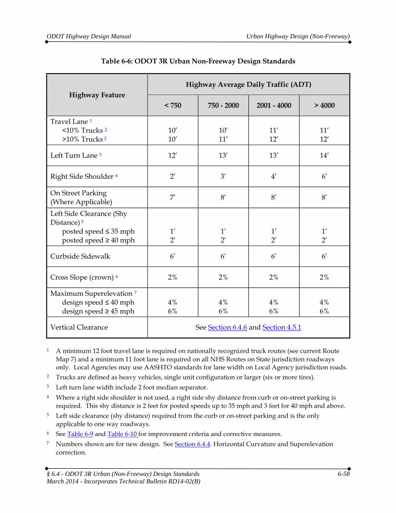
ODOT Highway Design Manual Urban Highway Design (Non-Freeway)
§ 6.4 - ODOT 3R Urban (Non-Freeway) Design Standards 6-58 March 2014 - Incorporates Technical Bulletin RD14-02(B)
Table 6-6: ODOT 3R Urban Non-Freeway Design Standards
Highway Feature Highway Average Daily Traffic (ADT)
< 750 750 - 2000 2001 - 4000 > 4000
Travel Lane 1 <10% Trucks 2 >10% Trucks 2
10’ 10’
10’ 11’
11’ 12’
11’ 12’
Left Turn Lane 3 12’ 13’ 13’ 14’
Right Side Shoulder 4 2’ 3’ 4’ 6’
On Street Parking (Where Applicable) 7’ 8’ 8’ 8’
Left Side Clearance (Shy Distance) 5
posted speed ≤ 35 mph posted speed ≥ 40 mph
1’ 2’
1’ 2’
1’ 2’
1’ 2’
Curbside Sidewalk 6’ 6’ 6’ 6’
Cross Slope (crown) 6 2% 2% 2% 2%
Maximum Superelevation 7 design speed ≤ 40 mph design speed ≥ 45 mph
4% 6%
4% 6%
4% 6%
4% 6%
Vertical Clearance See Section 6.4.6 and Section 4.5.1
1 A minimum 12 foot travel lane is required on nationally recognized truck routes (see current Route Map 7) and a minimum 11 foot lane is required on all NHS Routes on State jurisdiction roadways only. Local Agencies may use AASHTO standards for lane width on Local Agency jurisdiction roads.
2 Trucks are defined as heavy vehicles, single unit configuration or larger (six or more tires). 3 Left turn lane width include 2 foot median separator. 4 Where a right side shoulder is not used, a right side shy distance from curb or on-street parking is
required. This shy distance is 2 feet for posted speeds up to 35 mph and 3 feet for 40 mph and above. 5 Left side clearance (shy distance) required from the curb or on-street parking and is the only
applicable to one way roadways. 6 See Table 6-9 and Table 6-10 for improvement criteria and corrective measures. 7 Numbers shown are for new design. See Section 6.4.4. Horizontal Curvature and Superelevation
correction.
ODOT Highway Design Manual Urban Highway Design (Non-Freeway)
6.4.4 HORIZONTAL CURVATURE AND SUPERELEVATION
Each horizontal curve should be evaluated for design sufficiency compared to the ODOT Urban Standards. Deficient curves should be evaluated against criteria below to determine what level of corrective action, if any, is appropriate.
Evaluate reconstruction of horizontal curvature when the design speed of the existing curve is more than 15 mph below the project design speed, and the current year ADT is 2000 or greater. When curve reconstruction is not justified, appropriate mitigation measures such as those listed in Table 6-9 should be applied. Correction of the superelevation should be applied if the comfort speed of the curve is lower than the project design speed. If the comfort speed exceeds the project design speed, the superelevation should be maintained unless there is a justifiable reason to change it.
When curve reconstruction is not justified, appropriate mitigation measures such as those listed in Table 6-9 should be applied.
6.4.5 VERTICAL CURVATURE AND STOPPING SIGHT DISTANCE
Evaluate reconstruction of crest vertical curves if all of the following criteria are met:
1. The crest obstructs from view major hazards such as intersections, sharp horizontal curves, or narrow bridges, and the current year ADT is greater than 2000, or
2. The design speed based on the existing Safe Stopping Distance is more than 20 mph below the ODOT Urban Standards, and the current year ADT is greater than 2000.
If reconstruction of the vertical curve is not justified or cost effective, or the curve is not reconstructed to new construction standards, appropriate mitigation measures should be applied (See Table 6-9).
6.4.6 VERTICAL CLEARANCE
On projects utilizing ODOT 3R standards (Resurfacing, Restoration, and Rehabilitation), the vertical clearance of structures is considered over the entire roadway width, including usable shoulder width. For 3R projects, no reduction of the existing vertical clearance below the minimum vertical clearance is allowed. No reduction in vertical clearance is allowed if the existing vertical height is currently below the minimum vertical clearance.
Projects that do not meet these Vertical Clearance Standards will need to apply for a Design Exception and will require consultation with MCTD. MTCD will then involve the industry stakeholders in the consultation process necessary to fully evaluate user impacts, project construction, and design options. For additional information on Vertical Clearance over highways, see HDM Section 4.5.1. For vertical clearance requirements on Local Agency
§ 6.4 - ODOT 3R Urban (Non-Freeway) Design Standards 6-59 March 2014 - Incorporates Technical Bulletin RD14-02(B)
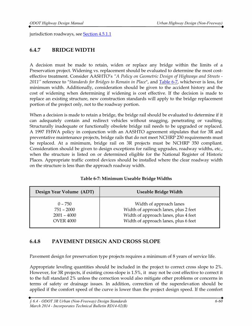
ODOT Highway Design Manual Urban Highway Design (Non-Freeway)
jurisdiction roadways, see Section 4.5.1.1
6.4.7 BRIDGE WIDTH
A decision must be made to retain, widen or replace any bridge within the limits of a Preservation project. Widening vs. replacement should be evaluated to determine the most cost-effective treatment. Consider AASHTO’s “A Policy on Geometric Design of Highways and Streets - 2011” reference to "Standards for Bridges to Remain in Place", and Table 6-7, whichever is less, for minimum width. Additionally, consideration should be given to the accident history and the cost of widening when determining if widening is cost effective. If the decision is made to replace an existing structure, new construction standards will apply to the bridge replacement portion of the project only, not to the roadway portion.
When a decision is made to retain a bridge, the bridge rail should be evaluated to determine if it can adequately contain and redirect vehicles without snagging, penetrating or vaulting. Structurally inadequate or functionally obsolete bridge rail needs to be upgraded or replaced. A 1997 FHWA policy in conjunction with an AASHTO agreement stipulates that for 3R and preventative maintenance projects, bridge rails that do not meet NCHRP 230 requirements must be replaced. At a minimum, bridge rail on 3R projects must be NCHRP 350 compliant. Consideration should be given to design exceptions for railing upgrades, roadway widths, etc., when the structure is listed on or determined eligible for the National Register of Historic Places. Appropriate traffic control devices should be installed where the clear roadway width on the structure is less than the approach roadway width.
Table 6-7: Minimum Useable Bridge Widths
Design Year Volume (ADT) Useable Bridge Width
0 – 750 751 – 2000 2001 – 4000 OVER 4000
Width of approach lanes Width of approach lanes, plus 2 feet Width of approach lanes, plus 4 feet Width of approach lanes, plus 6 feet
6.4.8 PAVEMENT DESIGN AND CROSS SLOPE
Pavement design for preservation type projects requires a minimum of 8 years of service life.
Appropriate leveling quantities should be included in the project to correct cross slope to 2%. However, for 3R projects, if existing cross-slope is 1.5%, it may not be cost effective to correct it to the full standard 2% unless the correction would also mitigate other problems or concerns in terms of safety or drainage issues. In addition, correction of the superelevation should be applied if the comfort speed of the curve is lower than the project design speed. If the comfort
§ 6.4 - ODOT 3R Urban (Non-Freeway) Design Standards 6-60 March 2014 - Incorporates Technical Bulletin RD14-02(B)
ODOT Highway Design Manual Urban Highway Design (Non-Freeway)
speed exceeds the project design speed the superelevation should be maintained unless there is a justifiable reason to change it.
6.4.9 SIDESLOPES AND CLEAR ZONE
As discussed earlier in Section 6.4.1 a roadside inventory shall be provided on all projects utilizing ODOT 3R Urban design standards. This inventory along with the accident summary and analysis gives the designer the information necessary to make good design decisions regarding safety improvements. Evaluation and improvement considerations of roadside features should be consistent with the following:
1. Flatten sideslopes of 1:3 or steeper at locations where run-off-road accidents are likely to occur (e.g., on the outside of horizontal curves).
2. Retain current slope ratios; do not steepen sideslopes, when widening lanes and shoulders unless warranted by special circumstances, such as flat existing slopes.
3. Remove, relocate or shield isolated roadside obstacles.
4. Remove vertical drop-offs at the edge of pavement after paving.
For ODOT 3R projects, Clear Zone issues are the responsibility of the Region Technical Center and should be documented in the project design narrative or related project files, as well as in a separate depository or library set up for the purpose of long term retention and future access as needed.
§ 6.4 - ODOT 3R Urban (Non-Freeway) Design Standards 6-61
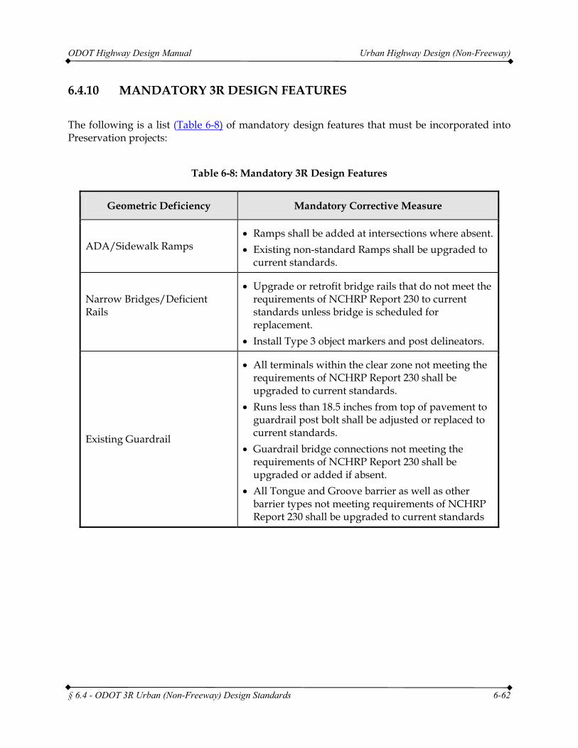
ODOT Highway Design Manual Urban Highway Design (Non-Freeway)
§ 6.4 - ODOT 3R Urban (Non-Freeway) Design Standards 6-62
6.4.10 MANDATORY 3R DESIGN FEATURES
The following is a list (Table 6-8) of mandatory design features that must be incorporated into Preservation projects:
Table 6-8: Mandatory 3R Design Features
Geometric Deficiency Mandatory Corrective Measure
ADA/Sidewalk Ramps • Ramps shall be added at intersections where absent. • Existing non-standard Ramps shall be upgraded to
current standards.
Narrow Bridges/Deficient Rails
• Upgrade or retrofit bridge rails that do not meet the requirements of NCHRP Report 230 to current standards unless bridge is scheduled for replacement.
• Install Type 3 object markers and post delineators.
Existing Guardrail
• All terminals within the clear zone not meeting the requirements of NCHRP Report 230 shall be upgraded to current standards.
• Runs less than 18.5 inches from top of pavement to guardrail post bolt shall be adjusted or replaced to current standards.
• Guardrail bridge connections not meeting the requirements of NCHRP Report 230 shall be upgraded or added if absent.
• All Tongue and Groove barrier as well as other barrier types not meeting requirements of NCHRP Report 230 shall be upgraded to current standards
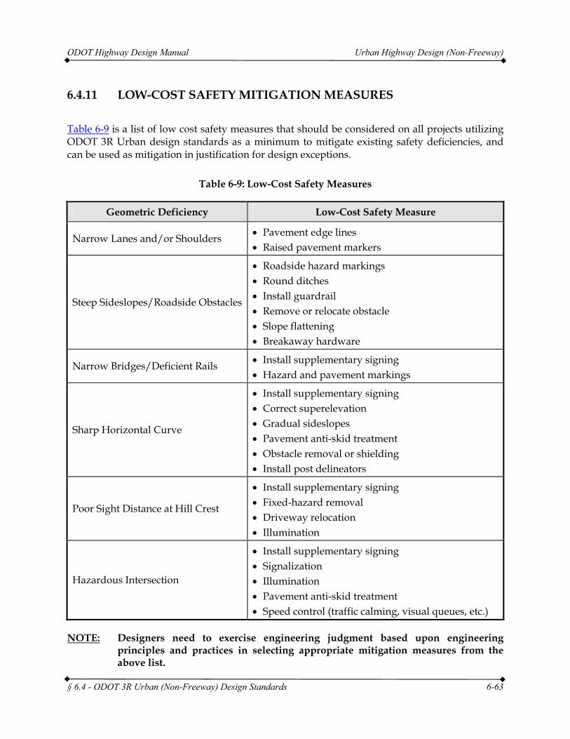
ODOT Highway Design Manual Urban Highway Design (Non-Freeway)
§ 6.4 - ODOT 3R Urban (Non-Freeway) Design Standards 6-63
6.4.11 LOW-COST SAFETY MITIGATION MEASURES
Table 6-9 is a list of low cost safety measures that should be considered on all projects utilizing ODOT 3R Urban design standards as a minimum to mitigate existing safety deficiencies, and can be used as mitigation in justification for design exceptions.
Table 6-9: Low-Cost Safety Measures
Geometric Deficiency Low-Cost Safety Measure
Narrow Lanes and/or Shoulders • Pavement edge lines • Raised pavement markers
Steep Sideslopes/Roadside Obstacles
• Roadside hazard markings • Round ditches • Install guardrail • Remove or relocate obstacle • Slope flattening • Breakaway hardware
Narrow Bridges/Deficient Rails • Install supplementary signing • Hazard and pavement markings
Sharp Horizontal Curve
• Install supplementary signing • Correct superelevation • Gradual sideslopes • Pavement anti-skid treatment • Obstacle removal or shielding • Install post delineators
Poor Sight Distance at Hill Crest
• Install supplementary signing • Fixed-hazard removal • Driveway relocation • Illumination
Hazardous Intersection
• Install supplementary signing • Signalization • Illumination • Pavement anti-skid treatment • Speed control (traffic calming, visual queues, etc.)
NOTE: Designers need to exercise engineering judgment based upon engineering principles and practices in selecting appropriate mitigation measures from the above list.
ODOT Highway Design Manual Urban Highway Design (Non-Freeway)
§ 6.4 - ODOT 3R Urban (Non-Freeway) Design Standards 6-64
6.4.12 3R URBAN PRESERVATION STRATEGY
The 3R Urban Preservation Strategy is a good place to utilize the ODOT Practical Design Policy. Urban areas are complex with many conflicting needs. An urban 4R project would attempt to rebuild and improve a roadway section on the whole. Where as, the intent of a 3R project is pavement preservation with improvements to selected design elements for safety and operations. Improvements to some of those design elements may be required by regulation or mandate. Other design elements may or may not be improved at the discretion of the project team. It is these elements where Practical Design can be employed to aid in the determination of the amount of value added to the system or corridor by making the improvements on either a wholesale basis or as an incremental improvement.
Due to the complexity and cost of urban preservation type projects, the Urban Preservation Strategy has developed a set of criteria for evaluating other design features for possible modifications or improvements. Table 6-10 contains the list of “Have To” and “Like To” corrective measures. The corrective measures listed under the “Have To” column must be addressed on all urban 3R preservation projects. The corrective measures listed under the “Like To” column should be considered where economically feasible (i.e., minimal extra cost or funds available from sources other than Preservation funding). Design exceptions are required for each design feature not meeting the “Have To” corrective measures.
Under some conditions, the “Like To” corrective measures are required as part of an Urban Preservation Project. These conditions include:
1. Pavement condition requiring reconstruction, or
2. Curb exposure less than 6 inches, or
3. Cross slope greater than 8%.
If any of these above conditions are met, design exceptions are required for not meeting the corrective measures from the “Like To” column of Table 6-10.
Urban Preservation projects must meet the design standards and features described above or obtain a design exception, depending upon certain conditions. However, it is often desirable to provide additional improvements in urban environments. Table 6-11 shows other design features that should be considered only if additional funding sources are available other than Preservation and where improvements are cost effective. This optional list is not a requirement for Urban Preservation projects and does not require design exceptions if these items are not included in a project.
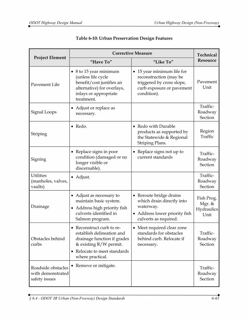
ODOT Highway Design Manual Urban Highway Design (Non-Freeway)
Table 6-10: Urban Preservation Design Features
Project Element Corrective Measure Technical
Resource “Have To” “Like To”
Pavement Life
• 8 to 15 year minimum (unless life cycle benefit/cost justifies an alternative) for overlays, inlays or appropriate treatment.
• 15 year minimum life for reconstruction (may be triggered by cross slope, curb exposure or pavement condition).
Pavement Unit
Signal Loops • Adjust or replace as
necessary. Traffic-
Roadway Section
Striping
• Redo. • Redo with Durable products as supported by the Statewide & Regional Striping Plans.
Region Traffic
Signing
• Replace signs in poor condition (damaged or no longer visible or discernable).
• Replace signs not up to current standards
Traffic-Roadway
Section
Utilities (manholes, valves, vaults)
• Adjust. Traffic-Roadway
Section
Drainage
• Adjust as necessary to maintain basic system.
• Address high priority fish culverts identified in Salmon program.
• Reroute bridge drains which drain directly into waterway.
• Address lower priority fish culverts as required.
Fish Prog. Mgr. &
Hydraulics Unit
Obstacles behind curbs
• Reconstruct curb to re-establish delineation and drainage function if grades & existing R/W permit.
• Relocate to meet standards where practical.
• Meet required clear zone standards for obstacles behind curb. Relocate if necessary.
Traffic-Roadway
Section
Roadside obstacles with demonstrated safety issues
• Remove or mitigate. Traffic-Roadway
Section
§ 6.4 - ODOT 3R Urban (Non-Freeway) Design Standards 6-65
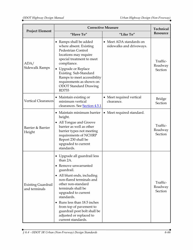
ODOT Highway Design Manual Urban Highway Design (Non-Freeway)
Project Element Corrective Measure Technical
Resource “Have To” “Like To”
ADA/ Sidewalk Ramps
• Ramps shall be added where absent. Existing Pedestrian Control locations may require special treatment to meet compliance.
• Upgrade or Replace Existing Sub-Standard Ramps to meet accessibility requirements as shown on ODOT Standard Drawing RD755
• Meet ADA standards on sidewalks and driveways.
Traffic-Roadway
Section
Vertical Clearances • Maintain existing or
minimum vertical clearances. See Section 4.5.1
• Meet required vertical clearance.
Bridge Section
Barrier & Barrier Height
• Maintain minimum barrier height.
• All Tongue and Groove barrier as well as other barrier types not meeting requirements of NCHRP Report 230 shall be upgraded to current standards.
• Meet required standard.
Traffic-Roadway
Section
Existing Guardrail and terminals
• Upgrade all guardrail less than 2A.
• Remove unwarranted guardrail.
• All blunt ends, including non-flared terminals and other non-standard terminals shall be upgraded to current standards.
• Runs less than 18.5 inches from top of pavement to guardrail post bolt shall be adjusted or replaced to current standards.
Traffic-Roadway
Section
§ 6.4 - ODOT 3R Urban (Non-Freeway) Design Standards 6-66
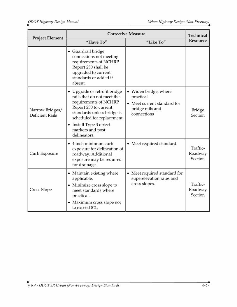
ODOT Highway Design Manual Urban Highway Design (Non-Freeway)
Project Element Corrective Measure Technical
Resource “Have To” “Like To”
• Guardrail bridge connections not meeting requirements of NCHRP Report 230 shall be upgraded to current standards or added if absent.
Narrow Bridges/ Deficient Rails
• Upgrade or retrofit bridge rails that do not meet the requirements of NCHRP Report 230 to current standards unless bridge is scheduled for replacement.
• Install Type 3 object markers and post delineators.
• Widen bridge, where practical
• Meet current standard for bridge rails and connections
Bridge Section
Curb Exposure
• 4 inch minimum curb exposure for delineation of roadway. Additional exposure may be required for drainage.
• Meet required standard. Traffic-
Roadway Section
Cross Slope
• Maintain existing where applicable.
• Minimize cross slope to meet standards where practical.
• Maximum cross slope not to exceed 8%.
• Meet required standard for superelevation rates and cross slopes. Traffic-
Roadway Section
§ 6.4 - ODOT 3R Urban (Non-Freeway) Design Standards 6-67
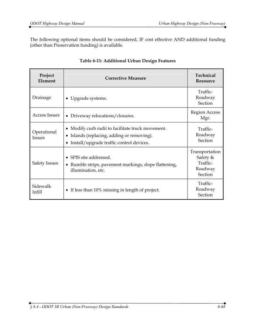
ODOT Highway Design Manual Urban Highway Design (Non-Freeway)
§ 6.4 - ODOT 3R Urban (Non-Freeway) Design Standards 6-68
The following optional items should be considered, IF cost effective AND additional funding (other than Preservation funding) is available.
Table 6-11: Additional Urban Design Features
Project Element Corrective Measure Technical
Resource
Drainage • Upgrade systems. Traffic-
Roadway Section
Access Issues • Driveway relocations/closures. Region Access
Mgr.
Operational Issues
• Modify curb radii to facilitate truck movement. • Islands (replacing, adding or removing). • Install/upgrade traffic control devices.
Traffic-Roadway
Section
Safety Issues • SPIS site addressed. • Rumble strips, pavement markings, slope flattening,
illumination, etc.
Transportation Safety & Traffic-
Roadway Section
Sidewalk Infill • If less than 10% missing in length of project.
Traffic-Roadway
Section
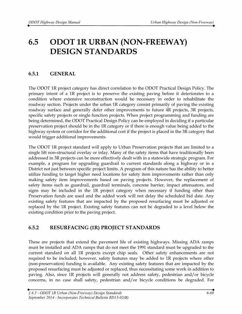
ODOT Highway Design Manual Urban Highway Design (Non-Freeway)
6.5 ODOT 1R URBAN (NON-FREEWAY) DESIGN STANDARDS
6.5.1 GENERAL
The ODOT 1R project category has direct correlation to the ODOT Practical Design Policy. The primary intent of a 1R project is to preserve the existing paving before it deteriorates to a condition where extensive reconstruction would be necessary in order to rehabilitate the roadway section. Projects under the urban 1R category consist primarily of paving the existing roadway surface and generally defer other improvements to future 4R projects, 3R projects, specific safety projects or single function projects. When project programming and funding are being determined, the ODOT Practical Design Policy can be employed in deciding if a particular preservation project should be in the 1R category or if there is enough value being added to the highway system or corridor for the additional cost if the project is placed in the 3R category that would trigger additional improvements.
The ODOT 1R project standard will apply to Urban Preservation projects that are limited to a single lift non-structural overlay or inlay. Many of the safety items that have traditionally been addressed in 3R projects can be more effectively dealt with in a statewide strategic program. For example, a program for upgrading guardrail to current standards along a highway or in a District not just between specific project limits. A program of this nature has the ability to better utilize funding to target higher need locations for safety item improvements rather than only making safety item improvements based on paving projects. However, the replacement of safety items such as guardrail, guardrail terminals, concrete barrier, impact attenuators, and signs may be included in the 1R project category when necessary if funding other than Preservation funds are used and the added work will not delay the scheduled bid date. Any existing safety features that are impacted by the proposed resurfacing must be adjusted or replaced by the 1R project. Existing safety features can not be degraded to a level below the existing condition prior to the paving project.
6.5.2 RESURFACING (1R) PROJECT STANDARDS
These are projects that extend the pavement life of existing highways. Missing ADA ramps must be installed and ADA ramps that do not meet the 1991 standard must be upgraded to the current standard on all 1R projects except chip seals. Other safety enhancements are not required to be included; however, safety features may be added to 1R projects where other (non-preservation) funding is available. Any existing safety features that are impacted by the proposed resurfacing must be adjusted or replaced, thus necessitating some work in addition to paving. Also, since 1R projects will generally not address safety, pedestrian and/or bicycle concerns, in no case shall safety, pedestrian and/or bicycle conditions be degraded. For
§ 6.5 - ODOT 1R Urban (Non-Freeway) Design Standards 6-69 September 2014 - Incorporates Technical Bulletin RD13-02(B)
ODOT Highway Design Manual Urban Highway Design (Non-Freeway)
example, a resurfacing project that is limited to the travel lanes shall not leave a seam, sunken drainage grates or other hazards in the shoulder or bike lane. Also, on facilities where the 1R standard is applied, it is intended that all safety features be inventoried and the applicable safety feature information is added to designated safety feature databases, and that the safety feature is addressed based on system priorities in stand alone projects or other STIP projects. When scoping 1R projects, the safety feature databases are used to identify opportunities to add safety enhancements with other (non-preservation) funding. Following is an outline of the ODOT Resurfacing 1R project standard design criteria. While the criteria primarily relate to the paving treatment and the ability to pave without degrading existing conditions, there may be corridors where analysis of the crash history indicates that a full 3R project is warranted. Therefore projects are screened for 1R eligibility from a safety perspective as well.
6.5.2.1 CRITERIA TO APPLY THE 1R STANDARD
A. 1R PROJECT REQUIREMENTS
1. A paving project is initially designated 1R based on the appropriate paving treatment – a single lift overlay or inlay. (There is no formal requirement for pavement design life for an individual project; however, since the 1R treatment is location specific, it is expected that an 8 year pavement life will be the goal of the program).
• Pavement Services is the final authority regarding the pavement design.
2. Where less than approximately 5% of a project (based on lane miles paved) includes more than a single lift non-structural overlay or inlay, the project may be designated 1R.
3. Where up to approximately 25% of a project (based on lane miles paved) includes more than a single lift non-structural overlay or inlay, the project may be designated 1R; however, this requires the approval of a design exception.
4. Where more than approximately 25% of a project (based on lane miles paved) includes more than a single lift non-structural overlay or inlay, the project must be designated 3R
• As an exception to this is rule, a grind and inlay plus an overlay may also be considered for development under the 1R standard; however, this would be uncommon and requires the approval of a design exception.
5. Where the appropriate course of action is not clear based on the percentages noted above, include Technical Services Roadway staff in the discussion.
6. The safety assessment may indicate that a paving project is best developed under the 3R standard (see below).
7. Chip seals are 1R projects and subject to the requirements of the 1R standard, including the roadside inventory. Chip seals do not require ADA work.
§ 6.5 - ODOT 1R Urban (Non-Freeway) Design Standards 6-70 September 2014 - Incorporates Technical Bulletin RD13-02(B)
ODOT Highway Design Manual Urban Highway Design (Non-Freeway)
8. The 1R Pavements and Region Roadway Managers Approval Form must be completed, signed, and submitted to Technical Services Roadway staff prior to the completion of project scoping.
a. Pavement Services Unit will be the technical resource for screening projects for 1R eligibility from a pavement design perspective (single lift treatment); identifying treatments or providing pavement design recommendations and reports.
b. The Region Roadway Manager will be responsible for screening projects for 1R eligibility from a safety features perspective.
9. Work does not degrade safety or bicycle/pedestrian facilities
10. Work does not reduce curb exposure below 4 inches.
11. Work does not result in a cross-slope in excess of 8%.
12. Work does not adversely affect drainage.
13. Work does not result in an algebraic difference greater than 11% at ADA ramps.
14. 1R project work typically does not change the existing striping. Modifying existing striping requires a design exception and shall consider ORS 366.215 impact.
15. All projects that include resurfacing (except for chip seals) shall install curb ramps where applicable.
16. All projects that include resurfacing (except for chip seals) shall bring curb ramps up to current standards; except, if a ramp meets the 1991 standard as a minimum, upgrading the ramp may be deferred.
17. Ramps that have been rendered nonfunctional over time from excessive settlement, degradation, or by subsequent overlays must be upgraded to current standards.
18. The following items of work are required in addition to paving where applicable.
a. Replacement of striping and delineation.
b. Gravel shoulders will match the paved surface elevation.
c. Replacement of signal loops if impacted
d. Replacement of rumble strips if impacted.
e. Adjust existing features that are affected by resurfacing
• Safety features (Guardrail, Barrier, etc.)
• Monuments
• Catch basins
§ 6.5 - ODOT 1R Urban (Non-Freeway) Design Standards 6-71 September 2014 - Incorporates Technical Bulletin RD13-02(B)
ODOT Highway Design Manual Urban Highway Design (Non-Freeway)
• Manholes
19. 1R projects in urban areas also require coordination with local projects with separate funding. For example, it is undesirable to finish paving and then shortly thereafter cut into the pavement for a culvert, sewage, drainage, utility or other type of project.
20. The 1R standard does not require addressing non-related substandard features of the roadway with a design exception request. However, the steps and processes required for the Vertical Clearance and Traffic Mobility Standards still apply and must still be followed (See Section 4.5).
21. All 1R projects will complete a Roadside Inventory to ensure that all substandard safety features are documented and asset management databases appropriately updated.
B. SCOPING REQUIREMENTS
In order to ensure the intent of the program is met in addressing pavement and safety needs, adequate advance information is needed to assure adequate statewide decisions are made.
1. FACS-STIP tool - Download existing roadside inventory at time of scoping
a. Identify pre-230 elements. Funds should be requested from the 1R Safety Features Upgrade Program or other funding sources as early in the process as possible. Replacement of pre-230 elements should be added to the 1R project if additional funds are available.
b. Identify any corners that must be upgraded for ADA
c. Drive through project and note any obvious safety issues not included in the existing inventory
2. Safety Assessment
a. The Safety Assessment is a formal review process established in each region to ensure the identification of any safety concerns where a 1R project is planned. It provides a basis for the Region Roadway Manager to sign the Roadway Managers Approval Form indicating it is appropriate to apply the 1R standard from a safety standpoint.
b. The Safety Assessment serves two key purposes: First, it needs to ensure that the safety issues are not best addressed through a 3R project rather than a 1R project; that analysis will review whether a crash hotspot exists in the project limits (e.g. a SPIS site) and whether the crash frequency and severity is such that a 3R project should be considered. Second, if the decision is made that the safety issues are not significant, it is important that the analysis examine safety treatments that avoid reducing safety and examine low cost safety treatments
§ 6.5 - ODOT 1R Urban (Non-Freeway) Design Standards 6-72 September 2014 - Incorporates Technical Bulletin RD13-02(B)
ODOT Highway Design Manual Urban Highway Design (Non-Freeway)
that are practical considering the roadway and roadside character with these locations and treatments expected to come from the systematic safety plans.
c. The Safety Assessment includes a review of the Department’s Roadway Departure Safety Plan, Intersection Safety Plan, forthcoming Pedestrian/Bicycle Safety Plan, and any other systematic safety plan that is developed. The Safety Assessment includes a list of crash hotspots. The safety assessment identifies recommended countermeasures that could be incorporated into the 1R project.
d. The Safety Assessment identifies funding sources (e.g. Safety funds, Maintenance funds) for additional work and proposes a schedule for safety work considering
• The extent of the safety work proposed, its staging, and traffic control
• Contractor and State forces availability
• The opportunities for bundling like safety work in larger contracts
• Recommended countermeasures should be added to the 1R project if additional funds are available.
e. If systemic plans are not current a more detailed analysis will be needed and such a crash history review should cover 3 to 5 years and will include at a minimum:
• The number and type of crashes
• The crash severity
• The crash rate and comparison to the average rate for type of facility
• Any SPIS sites and ranking
• The crash analysis should identify crash patterns, contributing factors, and outline potential solutions and remediation
f. If systemic plans are not current a more detailed countermeasure analysis process will need to be conducted and should consider:
• The significance of the existing crash pattern
• The possibility for changes in future traffic and roadway characteristics
g. Where critical safety issues need to be addressed and other funding is not available, it may be most appropriate to designate the paving project 3R. If critical safety needs are identified and the project is still to be progressed as a 1R project, the safety assessment must directly state the Region Traffic and Safety’s support for that approach.
h. The Region Traffic Engineer signs the safety assessment and provides a copy to the Region Roadway Manager as supporting documentation for signing the 1R Roadway Manager’s Approval Form. Technical Services Roadway Staff is also
§ 6.5 - ODOT 1R Urban (Non-Freeway) Design Standards 6-73 September 2014 - Incorporates Technical Bulletin RD13-02(B)
ODOT Highway Design Manual Urban Highway Design (Non-Freeway)
provided a copy and the Safety Assessment is marked complete on the 1R Tracking Spreadsheet.
C. PROJECT INITIATION REQUIREMENTS
At project initiation, the 1R Roadside Inventory must be completed to verify and update the data in the FAC-STIP tool (see section 11.1.5). The Safety Assessment must be reviewed and updated if necessary to ensure it is appropriate to continue to develop the project under the 1R Standard.
§ 6.5 - ODOT 1R Urban (Non-Freeway) Design Standards 6-74 September 2014 - Incorporates Technical Bulletin RD13-02(B)
ODOT Highway Design Manual Urban Highway Design (Non-Freeway)
6.6 ODOT SINGLE FUNCTION (SF) URBAN (NON-FREEWAY) DESIGN STANDARDS
6.6.1 GENERAL
The specific design standards used for a Single Function Standard project will generally be the same design standards used for a 4R/New Construction project. The difference is that the scope of work is very limited on SF projects, so the SF Standard does not require addressing non-related substandard features of the roadway. For example, if a guardrail upgrade qualifies as a Single Function project, it will not be necessary to address other substandard features on the roadway, such as lane and shoulder width, horizontal and vertical alignment, etc.
6.6.2 APPLICATION OF SINGLE FUNCTION (SF) PROJECT STANDARDS
Single Function projects include projects that are within the right of way but do not permanently impact the travel lanes or shoulders of the highway. Generally, projects that only include work outside the edge of pavement will qualify for the SF standard. The SF standard can also be applied to certain projects within the roadway such as re-striping projects as long as the final configuration of the travel lanes and shoulders is not changed in any way. These projects address a specific need. The scope of work is limited to features that are directly impacted as a result of addressing the specific need. For example, a signal upgrade at an urban intersection may impact the sidewalk and trigger the need to provide necessary ADA upgrades. In no case shall safety, operations, pedestrian and/or bicycle conditions be degraded as a result of a SF project. Each feature constructed in a SF project must be built to the applicable standard for new construction. The SF Standard does not apply to resurfacing projects.
§ 6.6 - ODOT Single Function (SF) Urban (Non-Freeway) Design Standards 6-75