unsteady forces on an accelerating plate and...
TRANSCRIPT

J. Fluid Mech. (2004), vol. 509, pp. 1–21. c© 2004 Cambridge University Press
DOI: 10.1017/S0022112004008821 Printed in the United Kingdom
1
Unsteady forces on an accelerating plate andapplication to hovering insect flight
By D. I. PULLIN1 AND Z. JANE WANG2
1Graduate Aeronautical Laboratories, 105-50, California Institute of Technology,Pasadena, CA 91125, USA
2Theoretical and Applied Mechanics, Cornell University, Ithaca, NY 14853, USA
(Received 7 August 2003 and in revised form 10 November 2003)
The aerodynamic forces on a flat plate accelerating from rest at fixed incidence intwo-dimensional power-law flow are studied analytically and numerically. An inviscidapproximation is made in which separation at the two plate edges is modelledby growing spiral vortex sheets, whose evolution is determined by the Birkhoff–Rott equation. A solution based on a similarity expansion is developed, valid whenthe scale of the separated vortex is much smaller than the plate dimension. Theleading order is given by the well-known similarity growth of a vortex sheet from asemi-infinite flat plate, while equations at the second order describe the asymmetricsweeping effect of that component of the free-stream parallel to the plate. Owing tosubtle cancellation, the unsteady vortex force exerted on the plate during the startingmotion is independent of the sweeping effect and is determined by the similaritysolution, to the order calculated. This gives a mechanism for dynamic stall based ona combination of unsteady vortex lift and pure added mass; the incidence angle formaximum vortex lift is arccos
√3/8 ≈ 52.2◦ independent of the acceleration profile.
Circulation on the flat plate makes no direct contribution. Both lift and drag forcepredictions from the unsteady inviscid theory are compared with those obtained fromnumerical solutions of the two-dimensional unsteady Navier–Stokes equations for anellipse of high aspect ratio, and with predictions of Wagner’s classical theory. Thereis good agreement with numerical results at high incidence and moderate Reynoldsnumber. The force per unit span predicted by the vortex theory is evaluated forparameters typical of insect wings and is found to be in reasonable agreement withnumerical simulations. Estimates for the shed circulation and the size of the start-upvortices are also obtained. The significance of this flow as a mechanism for insecthovering flight is discussed.
1. IntroductionThe aerodynamics of insect flight have drawn fascination from both biologists and
fluid dynamicists. See Weis-Fogh & Jensen (1956), Maxworthy (1981), Ellington(1984), Dickinson (1996) for reviews. For hovering flight, various aerodynamicmechanisms have been proposed for lift generation by the timewise periodic motionof flapping wings (Weis-Fogh 1973; Lighthill 1977; Ellington 1984; Ellington et al.1996; Dickinson, Lehmann & Sane 1999; Wang 2000a). An understanding of thisprocess can be viewed from two perspectives. The first refers to the near-wing vortexdynamics of producing local pressure lift in single wing strokes. Or equivalently, in

2 D. I. Pullin and Z. J. Wang
order to maintain lift over many wing cycles, an insect must create a flux of downwardmomentum in the direction of the gravity vector.
In terms of near-wing aerodynamics, it is clear that unsteady vortex separationduring the thrust stroke of the wing motion plays a crucial role in the production offorces on the heaving insect wing. This has been studied by direct numerical simulationof the Navier–Stokes equations in both two and three spatial dimensions; see Wang(2000a) and Sun & Tang (2002). Wang (2000a) conducted numerical simulations, usinga fourth-order finite difference scheme, of an elliptical wing undergoing a periodicheaving and pitching motion in a viscous fluid at Reynolds numbers of order 10−103.The wing motion was strictly two-dimensional but nevertheless appeared to capturethe essential features of the period-averaged force production via the generation of apair of unsteady vortices during the downward stroke, and, crucially, the combinationof the pair into a vortex dipole under the wing on the return stroke. This sequentialpair/dipole production, coupled with the dipole’s self-convection downward and awayfrom the wing, then produces induced momentum flux and a subsequent reaction forceon the body in a sense that can be qualitatively described by a momentum balanceapplied to the reverse von-Karman vortex street: see Milne-Thomson (1968) andSaffman (1992). In three dimensions the dipoles will probably be replaced by arraysof possibly interconnected vortex-ring-like structures. See also Rayner(1979a, b) for atheoretical calculation of induced power assuming the wake to be a stack of coaxialvortex rings, Ellington (1984) for related models of vortex wakes and Freymuth et al.(1991) for experimental flow visualization of the wake.
Theoretical analysis of force generation during the translating phase of a flappingwing has been primarily based on Kutta–Joukowski’s theory of a wing moving at aconstant velocity, which ignores the influence of the near-wing vorticity and the effectof acceleration. Moreover, the theories of Wagner (1925) (linear) and of von Karman& Sears (1938) (nonlinear) include only the trailing-edge vortices and, as a result,are applicable to small angle of attack. At large angles of attack, as in the case ofhovering insects, the separated vortices are better modelled by spiral vortex sheets,which assume a self-similar form at small times (Smith 1966; Pullin 1978; Saffman1992). This idea was used by Graham (1983) to estimate the initial development ofthe lift on an aerofoil in inviscid starting flow producedby vortex separation at thetrailing edge. He found singular behaviour at t = 0 for the impulsive case and alsoargued that corrections produced by the non-singular part of the velocity field nearthe separating edge could have significant influence at finite times. Recent work byJones (2003) formulated the separated flow around a moving plate using a regularizedboundary-integral representation and obtained numerical solutions at angles of attackclose to 90◦.
In the present paper we use a conformal map and extend the similarity approachto model the unsteady vortex force produced during an accelerating phase of aninsect wing stroke over the full range of angle of attack. The wing is modelled intwo dimensions by a flat plate at incidence in inviscid starting flow. Separation fromboth the leading and trailing edges is modelled by spiral vortex sheets whose timewiseevolution is asymmetrical about the normal to the wing centreline. The observationof Wang (2000a), that the vortex pair produced on the prior stroke quickly convectsaway from the wing, suggests that this localized model may be sufficient to analysethe vortex dynamics of lift generation.
In § 2, the inviscid vortex dynamics of separation from a flat-plate aerofoil of finitechord is discussed and a similarity expansion of the integro-differential equationgoverning growth of the edge vortices is developed. It is shown in § 3 that, to second

Unsteady forces on an accelerating plate 3
α
y'
y
x'
xL/2–L/2
U(t) = Btm
Figure 1. Definition of the plate motion and the two coordinate systems employed.
order, the effect of the finite part of the attached-flow velocity at the plate edgesproduces asymmetry in the growth of vortices from the leading and trailing wingedges but generates equal and opposite contributions to forces exerted on the wing,with subsequent cancellation. For small times, lift and drag forces on the wing aretherefore dominated by the self-similar vortex growth. Circulation on the wing doesnot contribute. In § 4 comparisons are made between the inviscid vortex theory, theclassical theory of Wagner (1925), and numerical solutions of the Navier–Stokesequations for starting flow about an elliptical wing of high aspect ratio. Applicationof the vortex theory to force generation in simplified models of insect hovering flightmotion is described in § 5. The implications of the current theory for the aerodynamicbasis of insect flight is discussed in § 6.
2. Flat plate in inviscid starting flow2.1. Unsteady force on moving plate
We consider two-dimensional starting flow about a flat plate of length L. Thiswill represent a model of part of an insect wing motion that is sufficiently simpleto be analytically tractable, yet which contains some of the essential dynamics ofthe unsteady vortex-lift generation process. In Cartesian coordinates (x, y), in alaboratory-fixed frame of reference at time t = 0, the plate is in y = 0, −L/2 � x � L/2(see figure 1). For t � 0, the plate moves into the third quadrant, without rotation,with speed U (t) and in a straight-line trajectory such that its centreline makes anangle α with the negative x-axis. The plate speed profile is of power-law form
U (t) = B tm, (2.1)
where m � 0 is a power exponent and B constant with dimensions Length ×Time−(1+m). This kinematic is chosen for analytical simplicity in describing theunsteady vortex dynamics of separation at the plate edges; it can be thought ofas a single-stroke wing motion. We wish to determine the time-dependent force onthe plate generated by the start-up flow for t � 0. It is assumed that the flow is two-dimensional and inviscid but the effect of viscosity ν in the limit ν → 0 is modelledby allowing separation at the plate edges x = ± L/2 in the form of a pair of unsteadyvortex sheets. These roll up into structures to be specified subsequently. The flow is

4 D. I. Pullin and Z. J. Wang
considered to be everywhere irrotational, save for the singular distribution of vorticityalong the vortex sheets.
It is convenient to work in a non-inertial frame of reference at rest with respectto the plate. In this frame let C(t) be a closed contour surrounding and immediatelyadjacent to the plate and both vortex sheets. We now introduce the complex potential
W (z, t) =φ(x, y, t) + i ψ(x, y, t), (2.2)
where z = x+i y, φ is the velocity potential and ψ is the stream function. The complexvelocity is u(x, y, t) − i v(x, y, t)=dW/dz and, at z → ∞, the complex velocity relativeto the plate is then U (t) − i V (t) = U (t) exp(−iα). Since the total circulation aroundthe plate–vortex system is always zero, the instantaneous force per unit length exertedby the fluid on the plate can be expressed as (Newman 1977; Milne-Thomson 1968)
Fy − i Fx = −ρd
dt
∮C(t)
[W (z, t) − W∞(z, t)] dz, (2.3)
W∞(z, t) = U (t) exp(−iα) z, (2.4)
where ρ is the fluid density, Fx , Fy are the components of the force per unit span onthe plate in the x- and y-directions respectively and the integration is anti-clockwiseon the contour C(t). W (z, t) must be such that, d[W (z, t) − W∞(z, t)]/dz ∼ O(z−2),z → ∞. Under these conditions, an integral on the right-hand side of (2.3) giving themomentum flux across, and the external pressure force on a large circle at infinitycan be shown to vanish.
2.2. Vortex-sheet model of edge separation
To construct W (z, t) we first introduce the conformal mapping
ζ (z) = 12(z +
√z2 − L2/4), (2.5)
that maps the z-plane exterior to the plate to the exterior of the circle |ζ | =L/4 inthe ζ -plane. The complex potential can now be written as
W (z, t) = U (t)wa(z) + Wv(ζ (z), t), (2.6)
where
wa(z) = z cosα − i sinα√
z2 − L2/4 (2.7)
gives the attached flow and Wv(z, t) is the complex potential produced by separationat the plate edges. The attached flow satisfies the boundary condition Im[wa] = 0, ony = 0, −L/2 <x <L/2 as it should, where Im denotes the imaginary part.
To construct the complex potential for the separated flow we introduce two freevortex sheets, each of which emanates from one of the two sharp edges at z = L/2,z = −L/2. Each vortex sheet, denoted by the complex functions Z+(Γ, t) and Z−(Γ, t)respectively, is paramaterized by Γ , where Γ is a Lagrangian parameter for each sheetthat lies in the range 0 < |Γ | < |Γ±(t)|. This is a standard representation of vortexsheets well-suited to a compact description of their dynamical evolution; see Saffman(1992). The parameter Γ is the total circulation concentrated on the sheet betweena point on the sheet and the sheet tip, and Γ±(t) is the total shed circulation attime t on sheet ±. The functions Z+(Γ, t) and Z−(Γ, t) satisfy the Euler dynamics ofvortex-sheet evolution for which Γ is a conserved quantity moving with the averagevelocity of two instantaneously adjacent fluid particles, one on each side of the sheet.

Unsteady forces on an accelerating plate 5
Now let
Z± = 12(Z± +
√Z2
± − L2/4), (2.8)
where Z± = Z±(Γ, t) are the vortex sheets mapped onto the ζ -plane. The complexpotential contributed by the separated vortex sheets at time t can then be written as
Wv(ζ, t) =1
2π i
∑±
∫ Γ±(t)
0
[log(ζ − Z±(Γ, t)) − log
(ζ − L2
16 Z∗±(Γ, t)
)]dΓ, (2.9)
where the sum, used here and elsewhere, is over the ± sheets, ∗ denotes the complexconjugate and where images of the sheets in the circle |ζ | =L/4 have been used tosatisfy the boundary condition for Wv , namely that ψv = Im[Wv] is constant on theplate surface in the z-plane.
The force on the moving plate can now be obtained by substituting (2.7) and (2.9)together with (2.5) into (2.6) and then into (2.3). For both the components contributedby the attached and separated flow, the resulting integrals can be readily evaluatedby expanding C(t) to infinity and applying the method of residues. The attached flowwa then gives the well-known result
F (a)y = ρ L2 sin α
π
4
dU (t)
dt. (2.10)
This is just the force produced by the attached-flow added mass accelerating atdU (t)/dt . For Wv , the contour integral is most easily handled in the ζ -plane, and it isfound that the additional force per unit length on the plate produced by the separatedflow is then
F (v)y − i F (v)
x = −ρd
dt
∑±
∫ Γ±(t)
0
(L2
16 Z∗±(Γ, t)
− Z±(Γ, t)
)dΓ. (2.11)
We shall refer to this as the vortex force.
3. Vortex dynamics3.1. Birkhoff–Rott equation
Evaluation of (2.11) requires a solution for the dynamical evolution Z±(Γ, t), orequivalently Z±(Γ, t), for given U (t). This can be obtained from the Birkhoff–Rottequation (Rott 1956) for the vortex sheet growing from z = (L/2, 0)
∂Z∗+(Γ, t)
∂t=
dW
dz(z = Z+(Γ, t)). (3.1)
Using (2.5)–(2.9), this can be written as
∂Z∗+(Γ, t)
∂t= B tm
(cosα − i Z+ sinα√
Z2+ − L2/4
)+
1
2
(1 +
Z+√Z2
+ − L2/4
)
× 1
2 π i
∫ Γ (t)
0
(1
Z+ − Z′+
− 1
Z+ − L2/(16 Z∗′+)
)dΓ ′, (3.2)
where Z+ ≡ Z+(Γ, t) and Z′+ ≡ Z+(Γ ′, t). In (3.2) we have omitted the velocity
induced on the vortex near z = L/2 by the vortex shed from z = −L/2. In the expansionthat follows, this term can be shown to be of higher formal order, for sufficiently small
6 D. I. Pullin and Z. J. Wang
t , than the order-one attached-flow velocity near z = L/2. Equation (3.2) is a highlynonlinear problem of vortex dynamics that will in general require numerical treatment.Presently we make use of an analytical approximation in the form of a similarityexpansion that, for finite plate length L, will provide an accurate description of thevortex dynamics only for times sufficiently small such that |Z+(Γ, t) − L/2|/L � 1.Although this condition will be seen to be violated at late times in application toinsect wing aerodynamics, the resulting force may nevertheless be expected to providea reasonable analytical estimate of the unsteady vortex force in terms of parametersthat characterize hovering flight.
3.2. Similarity expansion
The first term on the right-hand side of (3.2) is the complex velocity provided by theattached flow. If we put Z+ = Z+ − L/2 and expand in powers of Z+/L � 1 aboutZ+ = 0, it is found that, to leading order, this term is singular and of the form
dWa
dz(z =Z+) = − i
2a tm Z+
−1/2+ · · · , (3.3)
where
a =L1/2 B sinα. (3.4)
Equation (3.3) gives the attached flow past a semi-infinite flat plate for which there isno natural, fixed length scale. This can be used to construct a leading-order similaritysolution to (3.2), valid for sufficiently small t (Smith 1966; Pullin 1978), for which theappropiate time-dependent length scale is
δ(t) = K a2/3 t2(1+m)/3, (3.5)
K =
[3
4 (1 + m)
]2/3
, (3.6)
where K is a convenient scaling constant.The angle α affects the similarity sheet evolution for small t only through the
parameter a. Since the dominant term in the expansion of the attached-flow velocityis essentially the same near z = ±L/2, it follows that, at leading order, the vortexsheets shed from z = ± L/2 are symmetric about x = 0; their circulations are equaland opposite, as are their image circulations on the plate. The plate circulation istherefore zero. In what follows, we wish to obtain asymmetric corrections to theleading-order solution and to evaluate the subsequent effect on the vortex forceexerted on the plate. Motivated by (3.5), we thus introduce the similarity expansion
Z+(Γ, t) =L
2(1 + 2 ε2 ω0(λ) + 2 ε2+µ1 (t) ω1(λ) · · · ), (3.7)
Γ =δ2(t) t−1
K3/2(J0 + εµ2 (t) J1 + · · · ) (1 − λ), (3.8)
where ε = (δ(t)/L)1/2 � 1 is a time-dependent parameter and λ is a dimensionlesscirculation parameter. In (3.7)–(3.8), ω0(λ) and ω1(λ) are complex shape functions,and J0 and J1 are dimensionless constants to be determined. It will be arguedsubsequently that the exponents µ1 and µ2 must take the values µ1 =µ2 = 1, andthese values will now be assumed.

Unsteady forces on an accelerating plate 7
When (3.7) and (3.8) are substituted into (3.2), and an expansion in powers of ε(t)is made, after taking care with evaluation of the time derivative on the left-hand sideat fixed Γ , it is found that all terms scale as δ(t) t−1εp(t), p =0, 1, 2, . . . . Cancellingδ(t) t−1 uniformly and equating terms of order ε0 then gives
ω∗0 + Q (1 − λ)
dω∗0
dλ=
1
ω1/20
(−i +
J0
2 π i
∫ 1
0
F (ω0|ω′0) dλ′
), (3.9)
F (ω0|ω′0) =
1
ω1/20 − ω′
01/2
− 1
ω1/20 + ω∗′
0
1/2, (3.10)
where ω0 ≡ ω0(λ), ω′0 ≡ ω0(λ
′) and Q =(4 m + 1)/(2 m + 2). When λ→ 0, then ω0 → 0and the right-hand side of (3.9) is unbounded unless the (zeroth-order) Kutta conditionis satisfied:
1 +J0
2 π
∫ 1
0
F (0|ω0) dλ= 0. (3.11)
This condition determines J0. Equation (3.9) is a nonlinear integral equation definingω0(λ). Its numerical solution (Pullin 1978) gives the similarity solution for startingflow past a semi-infinite flate plate discussed above.
At O(ε), it is found that
3
2ω∗
1 + Q (1 − λ)dω∗
1
dλ+
J1
2 J0
(1 − λ)dω∗
0
dλ=2 cotα +
1
2
ω1
ω3/20
(i − J0
2 π i
∫ 1
0
F (ω0|ω′0) dλ′
)
− 1
ω1/20
J0
2 π i
∫ 1
0
G(ω0, ω1|ω′0, ω
′1) dλ′ +
1
ω1/20
J1
2 π i
∫ 1
0
F (ω0|ω′0) dλ′, (3.12)
where
2 G(ω0, ω1|ω′0, ω
′1) =
ω1ω′01/2 − ω′
1ω1/20
ω1/20 ω′
01/2
(ω
1/20 − ω′
01/2
)2− ω1 ω∗′
0
1/2+ ω∗′
1 ω01/2
ω1/20 ω∗′
0
1/2(ω
1/20 + ω∗′
0
1/2)2. (3.13)
Equation (3.12) is a singular but linear integral equation for ω1(λ). This gives acorrection to the similarity solution defined by (3.9) and can be solved only whenω0(λ) and J0 are known. When λ→ 0, then ω0 → 0 and ω1 → 0 (this follows from (3.7))and terms on the right-hand side contain singular factors. In this limit, using (3.9), theterms multiplied by ω
−3/20 may be shown to be bounded. Using (3.11), it follows that
the remaining terms on the right-hand side are bounded if the O(ε) Kutta condition
J1 − J 20
4 π
∫ 1
0
(ω1
ω3/20
+ω∗
1
ω∗3/20
)dλ= 0 (3.14)
is satisfied. This is sufficient to determine J1, which gives a correction to the vortexcirculation predicted by the similarity solution. We remark that, unless µ1 = µ2 = 1,it is not possible to relieve all singular terms in the expansion of (3.2) when λ→ 0,uniformly in time. Putting λ= 0 in (3.8) gives the circulation shed at time t
Γ+(t) = K1/2 a4/3 t4(1+m)/3−1(J0 + J1 K1/2 L−1/2 a1/3 t (1+m)/3 + · · ·
). (3.15)
From (3.7) with λ= 1 we obtain the locus of the vortex centre
Z+(0, t) = K a2/3 t2(1+m)/3(ω0(1) + K1/2 L−1/2 a1/3 t (1+m)/3ω1(1) + · · ·
). (3.16)

8 D. I. Pullin and Z. J. Wang
Equation (3.12) describes the effect of asymmetry in the vortex-sheet evolutionfrom the edge z = L/2. This is driven by the first term on the right-hand side, whichis produced by the ‘sweeping’ component of the fluid velocity at infinity tangentialto the plate. The α-dependence can be removed explicitly from (3.12) by rescaling,from which it follows that both J1 and ω1 are proportional to cotα. Althougha similar equation for the sheet shed at z = −L/2 can be obtained, this case canbe deduced using symmetry arguments applied to (3.12) as follows: for m � 0 andα < π/2 let ω0(λ) and J0, ω1(λ) and J1 be solutions to (3.9)–(3.11) and to (3.12)–(3.14)respectively, representing the leading-order and sweeping-asymmetry correction forthe sheet shed at z = L/2. Because α < π/2 (see figure 1), we denote this (+) sheet aleeward separation, and that (−) from z = −L/2 a windward separation. The effectof the sweeping asymmetry on the windward sheet can be inferred by replacing α byπ − α in (3.12)–(3.14). At fixed time t , we note that this has the effect of reflecting thewhole asymmetric vortex structure about the normal to the plate centreline (y-axis),so that the sheet from z = L/2 is then ‘windward’ while that from z = −L/2 becomes‘leeward’. But when α → π − α, it can be seen that (3.12)–(3.14) are invariant underω1 → −ω1 and J1 = → −J1. Applying this result to the sheet from z = −L/2, andtaking into account the reflection property discussed above, it follows that, whenα < π/2, the circulation and shape of this sheet are respectively
Γ−(t) = K1/2 a4/3 t4(1+m)/3−1(−J0 + J1 K1/2 L−1/2 a1/3 t (1+m)/3 + · · ·
), (3.17)
Z−(Γ, t) +L
2= K a2/3 t2(1+m)/3
(−ω∗
0(λ) + K1/2 L−1/2 a1/3 t (1+m)/3ω∗1(λ) + · · ·
). (3.18)
This result can also be obtained by the simple physical argument that, at fixed α, thesweeping flow is equal and opposite at the leading/trailing edges of the plate. Thedimensionless circulation on the plate produced by sweeping asymmetry is equal to2 J1.
3.3. Point-vortex model
The effects of asymmetry can be evaluated explicitly by the use of a point-vortexmodel. Here, for simplicity, the entire vortex sheet is concentrated into a single pointvortex joined by a cut in the z-plane to z = L/2. The point-vortex equations can beobtained by first replacing the Birkhoff–Rott equation by the requirement that theforce on the vortex-cut system be zero as the vortex increases in circulation and movesaway from z =L/2. This is then followed by the application of a similarity expansionanalogous to (3.7)–(3.8) to the result. An alternative is to integrate (3.9)–(3.14) in0 � λ � 1 and to identify the right-hand side with point-vortex kinematics. In eithercase care must be exercised in evaluating the point-vortex self-induction using Routh’stheorem (Milne-Thomson 1968). The results obtained using both methods agree, withthe result that the point-vortex similarity-expansion equations are, to leading order,
(1 + Q) ω∗0v = − i
ω1/20v
+J0
2 π i
(− 1
2 ω0v
+1
ω1/20v
Fv(ω0v)
), (3.19)
1 =J0
2 π
(1
ω1/20v
+1
ω∗1/20v
), (3.20)
Fv(ω0v) = − 1
ω1/20v + ω∗1/2
0v
, (3.21)
where ω0v is the leading-order position of the point vortex. The O(ε1) equations are
Unsteady forces on an accelerating plate 9
(32
+ Q)ω∗
1v +J1
2J0
ω∗0v = 2 cotα− J1
4π i ω0v
+J0 ω1v
4π i ω20v
+1
2
ω1v
ω3/20v
(i − J0
2 π iFv(ω0v)
)
− 1
ω1/20v
(J0
2 π iGv(ω0v, ω1v) − J1
2 π iFv(ω0v)
), (3.22)
with associated Kutta condition
J1 =J 2
0
4π
(ω1v
ω3/20v
+ω∗
1v
ω∗3/20v
), (3.23)
where
2 Gv(ω0v, ω1v) = − ω1v ω∗1/20v + ω∗
1vω1/20v
ω1/20v ω∗1/2
0v
(ω
1/20v + ω∗1/2
0v
)2, (3.24)
and ω1v is the O(ε1) correction to the point-vortex position in the similarity expansion.The point-vortex equations can be solved analytically. The solution to (3.19)–(3.21)
is (Rott 1956)
ω0v =i
21/3
(1 + m
3 + 6 m
)2/3
, J0 = 21/3π
(1 + m
3 + 6 m
)1/3
. (3.25)
When these results are substituted into (3.22)–(3.23), their solution can be obtainedas
ω1v =4 (1 + m)
7 + 13 mcotα
(1 +
i
3
), (3.26)
J1 = − 4
(2
3
)2/3(1 + m)2/3 (1 + 2 m)1/3
7 + 13 mπ cotα. (3.27)
When 0 < α < π/2, the effect of asymmetry on the vortex from z = L/2 is to weakenthe (positive) vortex circulation and to cause it to move outboard and further abovethe plane of the plate in comparison to the trajectory of the leading-order similaritysolution. The asymmetric effect on the vortex near z = −L/2 is the opposite: thevortex circulation increases in magnitude (becomes more negative) and the vortexmoves, relatively, inboard and towards the plate surface. Cortelezzi & Leonard (1993)obtained a point-vortex solution for power-law starting flow past a semi-infinite flatplate in the presence of parallel plate motion, also of power-law form in time. Theyconsider cases for which the power exponents of t for these velocities are generallydifferent. For an appropriate choice of matching parameters, (3.25)–(3.27) are inagreement with their equations (24).
3.4. Vortex force exerted on plate
The vortex force can now be evaluated by applying (3.7)–(3.8) to (2.11). First writethis equation as
F (v)y − i F (v)
x = −ρd
dt(I+(t) + I−(t)) , (3.28)

10 D. I. Pullin and Z. J. Wang
where I+(t), I−(t) are the integrals in (2.11) contributed by the vortices shed at z = L/2,z = −L/2 respectively. Applying (3.7)–(3.8) to I+(t), gives, after some algebra
I+(t) = −L1/2 δ5/2(t) t−1
2 K3/2
[J0
∫ 1
0
(ω
1/20 + ω∗
01/2)
dλ + ε(t)
(J1
∫ 1
0
(ω
1/20 + ω∗
01/2)
dλ
+ J0
∫ 1
0
(ω1
2 ω1/20
+ω∗
1
2 ω∗01/2
+ ω0 − ω∗0
)dλ
)+ O(ε2)
]. (3.29)
A similar expression can be obtained for I−(t). When these results are used in (3.28)together with (3.17)–(3.18), it is found that the O(ε) contribution to the vortex forcecontributed by asymmetric corrections vanishes owing to cancellations. As a result,the vortex force can be expressed as
F (v)y = 2
(5 m + 2
3
)K ρ L1/2 J0 a5/3 t5 (1+m)/3−2 Re
[∫ 1
0
ω1/20 (λ) dλ
]+ O
(t7 (m+1)/3
),
(3.30)
where the cancelling terms are each of O(t2m). In (3.30), the leading-order power-lawscaling in time agrees with Graham (1983). The present result, that the leading-order,asymmetric correction to the vortex force vanishes can be understood as follows:the relative movements of the separated vortex systems produced by asymmetry willtend to enhance vortex-induced, low-pressure suction under the windward vortex asit moves inboard near z = −L/2, while relieving this effect near the leeward vortex,which moves outboard from z = L/2. To the order calculated, these effects cancel. Thepresence of circulation on the plate, produced by asymmetry in the two shed vortices,plays no direct role in the mechanism of force production. The integral in (3.30) canbe estimated either from the point-vortex solution (3.25) or from detailed similaritysolutions for the vortex-sheet evolution. The latter show that ω0(λ) is a function thatoscillates rapidly about the centre of roll-up ω0(1). Hence, for present purposes weapproximate
Re
[∫ 1
0
ω1/20 (λ) dλ
]≈ Re
[ω
1/20 (λ = 1)
]. (3.31)
The numbers J0 and ω0(1) used here are from Pullin (1978) but the point-vortexsolution could also be used to provide an approximate analytical expression for thevortex force.
4. Comparison with Navier–Stokes simulations and Wagner’s theoryWe now compare the unsteady forces derived above to the Navier–Stokes
simulations of an accelerating ellipse at angles of attack ranges from 0◦ to 90◦.In particular, we shall consider the linearly accelerating case, where m =1. For thispurpose it is convenient to rotate axes by α in the counter-clockwise direction onto axes (x ′, y ′), with rotation matrix [R(α)], such that (x ′, y ′)T =[R(α)](x, y)T . In the(x ′, y ′) system, the ellipse accelerates in the negative x ′-direction with velocity U (t)and at angle of attack α.
4.1. Wagner theory
In the case of small α, it is also appropriate to compare our results with predictionsfrom Wagner’s classical theory of an unsteady airfoil (Wagner 1925). The maindifference between Wagner’s theory and the present approach is the assumption

Unsteady forces on an accelerating plate 11
about the shed vortices. Wagner includes the vortex shed from the trailing edge only,which is a reasonable approximation at small angle of attack. In addition, Wagner’stheory ignores the roll-up of the vortex sheet, but assumes that the vortex distributionshed at time t is convected by U (t), the velocity of the airfoil at time t . Despitethese simplifications, Wagner’s theory predicts the unsteady circulation around anaccelerating airfoil remarkably well, as verified by the experiments of Walker (1931).
In the case of m =1, Wagner’s theory predicts (von Karman & Burgers 1963;Childress 1981)
F wx ′ =
d
dt(m′
11U ), (4.1)
F wy ′ = ρπLU 2(t) sinα +
d
dt(m′
21U (t)) +1
2ρU (t)L
∫ X(t)
0
γ (ξ, t)√Lξ + ξ 2
dξ, (4.2)
where X(t) the distance travelled, γ (ξ, t) is the circulation per unit length in the x-direction of the vortex sheet shed at the trailing edge, and m′
11, m′21 are components of
the added mass tensor m′ij . In the x ′, y ′ coordinates, [m] = [R−1(α)][m′][R(α)], where
[m] is the added mass tensor in the x, y or body coordinates, and [R(α)] the rotationmatrix between the two coordinate systems. At small time (ξ/L � 1), the integral in(4.2) can be approximated by
L
∫ X(t)
0
γ (ξ, t)√Lξ + ξ 2
dξ ∼∫ X(t)
0
γ (ξ, t)
√L + ξ
ξdξ,
∼ −πLU (t) sin α, (4.3)
and therefore
F wy ′ = 1
2ρπLU 2 sinα +
d
dt(m′
21U ), (4.4)
where the first term is equal to half of the steady state value. The net force due tocirculation is orthogonal to the relative flow at infinity.
In contrast, the vortex force predicted from the current theory is normal to theplate, and from (3.31) and using (3.4) with m =1 it is found that
Fn = 143ρ K J0 B5/3 L4/3 sin5/3 α t4/3 Re
[∫ 1
0
ω1/20 (λ) dλ
]. (4.5)
The vortex-sheet similarity solutions give J0 = 2.2, and the integral ∼ 0.32. Here wetake B = 4, L =2. The force components in the x ′- and y ′-directions are
Fy ′ = Fn cosα + m′21
dU
dt, (4.6)
Fx ′ = Fn sinα + m′11
dU
dt, (4.7)
For a translating ellipse of major and minor axes a and b, mij are given by
m11 = −ρπb2, (4.8)
m22 = −ρπa2, (4.9)
m12 = m21 = 0. (4.10)
The flat plate corresponds to b =0, a = L/2.
12 D. I. Pullin and Z. J. Wang
4.2. Navier–Stokes simulations
To obtain the unsteady force on an accelerating, non-rotating ellipse, we solve thetwo-dimensional Navier–Stokes equation in vorticity–stream function formulation inelliptic coordinates (Wang et al. 2004),
∂(Sω)
∂t+ (
√Su · ∇)ω = ν�ω, (4.11)
∇ · (√
Su) = 0. (4.12)
where u is the velocity field, ω the vorticity field, and S the local scaling factorS(µ, θ) = C2
0 (cosh2 µ−cos2 θ) resulting from coordinates transformation. The derivat-ives are with respect to the elliptic coordinates (µ, θ). The conformal transformationis given by
x + iy = c0 cosh(µ + iθ). (4.13)
In the two-dimensional vorticity–stream function formulation, the non-inertial frameintroduces only one extra term, the rotational acceleration of the wing, which isabsent for the present case of strictly linear acceleration. Other non-inertial terms canbe expressed as a gradient of a potential function. Thus they can be absorbed intothe pressure term. The curl of the gradient of pressure is zero. The body motion isreflected in the far-field boundary conditions, and the no-slip boundary condition atthe wing is enforced explicitly through the vorticity and stream function boundaryconditions.
The velocity and vorticity are solved in the accelerating body coordinates, (x, y),and are then transformed into the inertial frame. Navier–Stokes computations wereperformed for an ellipse with a constant acceleration along the negative x ′-axis (seefigure 1), with m =1, U (t) = 4t , so B = 4 in (2.1). In computational units, a =L/2 = 1,b =0.125. The ellipse travels a chord length over a unit time in this case. The viscosityis chosen such that the Re ≡ U (t) L/ν =800 at t = 1.
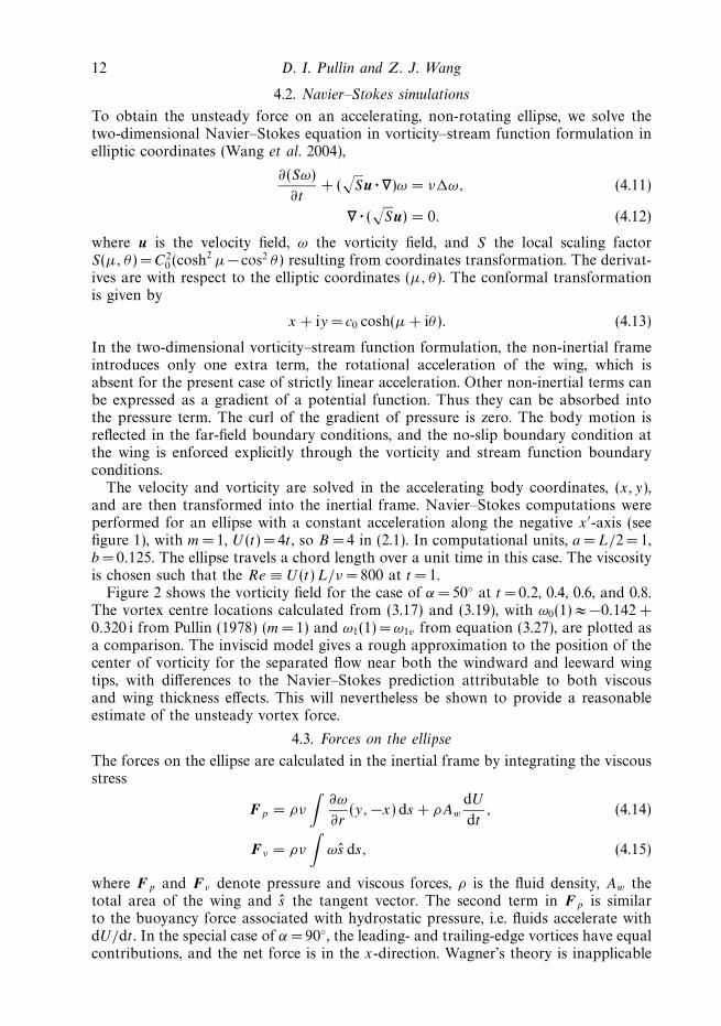
Figure 2 shows the vorticity field for the case of α = 50◦ at t = 0.2, 0.4, 0.6, and 0.8.The vortex centre locations calculated from (3.17) and (3.19), with ω0(1) ≈ −0.142 +0.320 i from Pullin (1978) (m =1) and ω1(1) = ω1v from equation (3.27), are plotted asa comparison. The inviscid model gives a rough approximation to the position of thecenter of vorticity for the separated flow near both the windward and leeward wingtips, with differences to the Navier–Stokes prediction attributable to both viscousand wing thickness effects. This will nevertheless be shown to provide a reasonableestimate of the unsteady vortex force.
4.3. Forces on the ellipse
The forces on the ellipse are calculated in the inertial frame by integrating the viscousstress
Fp = ρν
∫∂ω
∂r(y, −x) ds + ρAw
dU
dt, (4.14)
Fν = ρν
∫ωs ds, (4.15)
where Fp and Fν denote pressure and viscous forces, ρ is the fluid density, Aw thetotal area of the wing and s the tangent vector. The second term in Fp is similarto the buoyancy force associated with hydrostatic pressure, i.e. fluids accelerate withdU/dt . In the special case of α = 90◦, the leading- and trailing-edge vortices have equalcontributions, and the net force is in the x-direction. Wagner’s theory is inapplicable

Unsteady forces on an accelerating plate 13
(b)
(c) (d)
(a)
1
0
–1
1
0
–1
1
0
–1
1
0
–1
–2 –1 0 1 2 –2 –1 0 1 2
–2 –1 0 1 2–2 –1 0 1 2
Figure 2. The vorticity field in the case of α = 50◦. Grey scale indicates the vorticity strength.The ∗ mark the positions of the vortices calculated from the inviscid point-vortex model. Thearrow indicates the direction of the acceleration. Axes labels are omitted. (a) t = 0.2, (b) 0.4,(c) 0.6, (d) 0.8. Other parameters are m= 1, U = 4t , L = 2, e =0.125.
100
0.5 1.0 1.5 2.0
50
0
t
Fx'
Figure 3. Comparison of theoretical and computational forces for a special case, α = 90◦:present theory (dashed lines with circles) and computational results (solid line). Wagner’stheory (dash-dotted line with squares) is inapplicable here. Ellipse thickness ratio, e = 0.125,and the velocity, U (t)= 4t .
here, but the present theory is expected to work best in this case since the symmetrybetween the leading and trailing edge vortices is exact. It is seen in figure 3 that thetheoretical prediction fits the computational force up to t = 2, or equivalently, up to4 chords of travel, beyond the small time scale assumed by the theory.
To be consistent with the conventional definition of lift and drag in airfoil theory,the forces are decomposed into drag, Fx ′ , anti-parallel to wing motion, and lift, Fy ′
orthogonal to wing motion, indicated in figure 1. Figure 4 shows the comparison ofthe two theories and the computed force at angles seen in insect flight, 30◦–60◦. Asexpected, Wagner’s theory is a better approximation of lift (Fy ′) at small angle ofattack while the present theory works better at higher angle of attack. At α = 30◦,Wagner’s theory follows the computed Fy ′ closely up to t ∼ 1.8, while the presenttheory starts to deviate at t ∼ 1. At α =60◦, Wagner’s theory overpredicts computed

14 D. I. Pullin and Z. J. Wang
Fx'
Fx'
Fy'
Fy'
60
40
20
0.5 1.0 1.5 2.0
0.5 1.0 1.5 2.0
0.5 1.0 1.5 2.0
0.5 1.0 1.5 2.0
0.5 1.0 1.5 2.0
0.5 1.0 1.5 2.0
0.5 1.0 1.5 2.0
0.5 1.0 1.5 2.0
0
100
50
0
100
50
0
100
50
0
100
50
0
100
50
0
100
50
0
100
50
0
α = 30°α = 40°
α = 50°
t t
α = 60°
Figure 4. Comparison of theoretical and computational forces: present theory (dashed lineswith circles); Wagner’s theory (dash-dotted line with squares); and computational results (solidline). e = 0.125, and U = 4t .
Fy ′ starting at t ∼ 0.5, while the vortex theory agrees well up to t ∼ 2. By definitionWagner’s theory does not predict Fx ′ other than the component contributed by theattached-flow added mass. In contrast, the vortex theory is uniformly valid in α and soprovides estimates of Fx ′ that appear to work especially well at stalled angles. Navier–Stokes calculations were also carried out for an ellipse of higher thickness ratio,e =0.25. The forces were found to be almost identical to the results for e = 0.125,shown in figures 3 and 4.
5. Application of vortex theory to insect hovering flight5.1. Lift coefficients in single-stroke horizontal motion
We now use the vortex theory to calculate the average normal forces produced bystarting flow to time t = ts , and use these to estimate unsteady aerodynamic forces ininsect hovering flight. In (x, y)-coordinates, where y is normal to the plate surface,the average normal forces on the plate to time t = ts are
F(a)y =
1
ts
∫ ts
0
F (a)y (t) dt, F
(v)y =
1
ts
∫ ts
0
F (v)y (t) dt, (5.1)

Unsteady forces on an accelerating plate 15
where F(a)y , F
(v)y are the average added mass (attached flow) and vortex normal forces
per unit length respectively. From (2.10) and (3.30), these are
F(a)y =
π
4ρ L2 B sinα tm−1
s , (5.2)
F(v)y = 2 ρ K J0 B5/3 L4/3 sin5/3 α t5(1+m)/3−2
s Re
[ ∫ 1
0
ω1/20 (λ) dλ
], (5.3)
where (3.4) has been used.We define two normal force coefficients for power-law motion for time ts by
C(a)y =
F(a)y
12ρ L u2
, C(v)y =
F(v)y
12ρ L u2
, (5.4)
where u= S/ts is the mean speed and the stroke length is
S =1
1 + mB t1+m
s . (5.5)
In order to make comparisons with measurements and computation for a single wingstroke in the horizontal direction at angle of attack α, it is convenient to rotate to(x ′, y ′)-axes, with corresponding lift coefficients
C(a)L = C(a)
y cos α, C(v)L = C(v)
y cos α, CL = C(a)L + C
(v)L . (5.6)
These can now be estimated by use of (5.2) and (5.3). When (5.5) is used to eliminateB , it is found that
C(a)L =
π
2(1 + m) sinα cos α
(L
S
), (5.7)
C(v)L = 4 J0(1 + m)
(3
4
)2/3 (L
S
)1/3
sin5/3 α cos α Re
[∫ 1
0
ω1/20 (λ) dλ
]. (5.8)
Of interest is the (L/S)1/3 dependence of the vortex-lift coefficient with exponentindependent of m. To obtain numerical estimates, the wing chord is taken asL = 0.01 m with stroke S = 0.025 m and frequency f =40 Hz giving ts = 0.0125 s.These are typical of dragonfly wings. The lift coefficients for m =0.5 are shownin figure 5. It can be seen that the lift is dominated by the vortex force but theattached-flow contribution to the single-stroke lift coefficient is not negligible. From(5.8) the vortex lift is maximum at α = arcos
(√3/8
)≈ 52.2◦, independent of m while
the attached-flow single-stroke lift is maximum at α = 45◦. The total lift coefficientis maximized at a value of α somewhere between these values. Thus the vortex-lifttheory provides a mechanism for delayed/dynamic stall.
Total lift coefficients for three values of m are shown in figure 6 compared tothe results of experiment (Dickenson & Gotz 1993) and direct simulation (Wang2000a), at Reynolds number of order 200. Both the experiments and the numericswere obtained for a wing moving at constant velocity at a fixed incidence. Therefore,the comparison here is mainly about the α dependence of CL.
5.2. Forces in hovering flight
We now make numerical estimates of time-averaged forces in hovering flight for twodrastically simplified profiles of wing motion. In each case the wing is modelled intwo-dimensional flow by the present flat plate of chord L which moves in a periodic

16 D. I. Pullin and Z. J. Wang
2.0
1.5
1.0
0.5
20 40 60 800α (deg.)
CL
Figure 5. Lift coefficients, m= 1/2. L = 0.01 m, S = 0.025 m. Dashed line, vortex-lift coefficientC
(v)L . Solid line, total-lift coefficient CL. The difference is the attached-flow lift coefficient C
(a)L .
2.5
2.0
1.5
1.0
0.5
α (deg.)0 20 40 60 80
CL
Figure 6. Total lift coefficients CL during lift stroke. Dash-dot line, m= 0; dashed line,m= 1/2; solid line, m= 1. L = 0.01 m, S = 0.025 m. Filled circles, direct numerical simulation,Re = 192 (Wang 2000a); open squares, experiment (Dickenson & Gotz 1993).
motion with frequency f = 1/T where T =2 ts is the period. The first profile, denotedI, is an approximation to that used in the numerical simulations of Wang (2000b),where the wing moves in a combined pitching and heaving motion along a line atπ/3 to the horizontal. For simplicity we ignore the pitching motion, so that the wingremains horizontal (parallel to the x-axis) during a downward, or lift stroke, andmoves a stroke length S in the time interval 0 � t � ts as described in § 2.1, at aconstant angle α = π/4 to the negative x-axis. It is this stroke that produces the entirevortex force during the wing cycle. During the interval ts � t � T , the wing sheds thevortices by a return motion unspecified here but similar to that described by Wang(2000b). During the return stroke, the wing produces no overall contribution to theforce save that required to just cancel the attached-flow force (2.10); it is well-knownthat this force must average zero in the periodic translational motion of a rigid

Unsteady forces on an accelerating plate 17
m FL [N m−1] Γ+(ts) [m2 s−1] Γ−(ts) [m2 s−1] δ/L
0 0.018 0.019 −0.066 0.511/2 0.021 0.028 −0.088 0.511 0.025 0.037 −0.11 0.42
Table 1. Average force and other parameters, wing cycle I. L = 0.01 m,S = 0.025 m, ts = 0.0125 s.
m FL [N m−1] Γ+(ts) [m2 s−1] Γ−(ts) [m2 s−1] δ/L
0 0.027 0.028 −0.071 0.551/2 0.030 0.039 −0.095 0.491 0.037 0.051 −0.121 0.45
Table 2. Average force and other parameters, wing cycle II. L = 0.01 m,S = 0.025 m, ts = 0.0125 s.
two-dimensional body. With this model of the wing motion, the average vortex forceover the period T in the y-direction, taken as the vertical for this cycle, is then one-halfof that given by (5.3). The average force per unit length averaged over T = 2 ts cannow be expressed as
Fy = 12F
(v)y
= 14ρ L
(S
ts
)2
C(v)y . (5.9)
In this expression, only the vortex force contributes. We utilize previous values forL, S and ts , with α = π/4. Values for the average normal force and other parametersdefined previously for three values of m are shown in table 1. Values of the vortex forceper unit span are somewhat lower than that found by Wang (2000b), 0.026 N m−1,from unsteady simulations of sinusoidal motion at Reynolds number of 1256 basedon chord and maximum velocity. The normal force shows rather weak dependence onm when S is fixed. Also shown in table 1 are point-vortex estimates of the circulationsshed from the two wing edges at t = ts , and δ(ts)/L. It can be seen that this ratio notsmall compared with unity as formally required by the theory but the estimated sizeof the shed vortices is nevertheless of order those found by Wang (2000b) towardsthe end of the thrust stroke.
In a second model wing cycle, denoted II, it is convenient to work in (x ′, y ′)-axes,where the plate centerline moves with power-law velocity along the negative x ′-axisin 0 � t � ts , remaining at constant angle of attack α = 52.2◦. The lift coefficientis then given by (5.8). At t = ts , the wing halts and rotates instantaneously through75.6◦ clockwise, shedding the vortex pair, and then executes a power-law motion inthe positive x ′-direction at angle of attack α = 52.2◦. Following further instantaneousdeceleration and counterclockwise rotation, the cycle is repeated. If it is assumed thatthe half-cycle rotations do not contribute to the overall lift (this could be estimatedusing an extension of the present model; see also discussion in § 6), the time-averagedvortex force in the y ′-direction, taken as the vertical for this cycle, can be obtainedfrom (5.8). Numerical values shown in table 2 are substantially larger than thoseobtained for cycle I.

18 D. I. Pullin and Z. J. Wang
6. DiscussionThe present theory provides a theoretical basis for two effects observed in studies
of insect flight. First, it is well-known that most hovering insects employ anglesof attack much higher than the stalled angle of an airfoil. Typical values during thetranslational phase are about 25◦–45◦ in normal hovering (Ellington 1984). Dragonfliesand butterflies employ even higher angles of attack. At these ‘stalled’ angles, the wingcan generate higher transient lift coefficients compared to the steady-state value, aphenomenon called dynamic stall. Recent discussions have mainly focused on therole of dynamic stall on lift enhancement (Dickinson & Gotz 1993; Ellington et al.1996; Wang 2000b). A side effect of dynamic stall is the increase of drag. In factat such high angle of attack, it is no longer most convenient to separate lift anddrag in the traditional sense, which was appropriate for an unstalled airfoil. Wangrecently argued that insects might use both lift and drag to manoeuvre in air (Wang2003). In particular, a wing executing idealized kinematics similar to those used bydragonflies uses mostly pressure drag to generate the vertical force to hover (Wang2003). Classical steady and unsteady airfoil theories, however, were designed to treatthe regime of small angle of attack where the flow is attached at the leading edge;they do not predict pressure drag. To extend these theories to a full range of angleof attack, it is necessary to include both the leading- and trailing-edge vortices.The theory presented here is a second-order unsteady theory for a stalled airfoil.In § 5.1 it was shown that the combination of vortex and attached-flow added massforces produces a maximum lift coefficient at an angle between 45◦ and 52.2◦, in fairagreement with observation.
Second, a reciprocating insect wing must accelerate and decelerate periodically nearwing reversal. The unsteady forces associated with such an acceleration are neglectedin the classical quasi-steady theory, which includes only the term depending on thetranslational velocity (Weis-Fogh & Jensen 1956; Weis-Fogh 1973). Added mass(attached flow) is the simplest contribution to the force due to wing acceleration, butis not necessarily the dominant contribution. Another effect of the wing accelerationon the force generation is related to the unsteady growth of vorticity and the presenceof the vorticity near to the wing. Their effects have been investigated in the recentexperiments and computations of two families of wing kinematics. One consists ofconstant translation in the middle of the stroke and sharp accelerations near theend of the stroke (Dickinson et al. 1999; Sun & Tang 2002), and another simplesinusoidal motions (Wang, Birch & Dickinson 2004). The differences between themeasured forces and the steady-state theory based on translational velocity alonehave been a subject of recent discussions. The proposed mechanisms for the observedpeaks near wing reversal include the wing–wake interaction (Dickinson et al. 1999;Birch & Dickinson 2003), wing rotation during reversal (Dickinson et al. 1999; Sane& Dickinson 2002), and wing acceleration (Sun & Tang 2002). All of them still requirefurther clarification and theoretical analysis.
The present analysis allows quantification of unsteady forces due to accelerationnear the wing reversal. For power-law start-up velocity given by (2.1), the contributionof pure added mass and separated vorticity provides start-up forces proportional totm−1, m �= 0, and t (5 m−1)/3 respectively. If wing reversal is modelled by impulsivestart-up, m =0, at t = 0, the corresponding forces are proportional to δ(t), wherehere δ denotes the Dirac delta function, and t−1/3 respectively, and are thereforeunbounded when t → 0+. This suggests peaked starting forces in periods of rapidacceleration/deceleration at wing reversal. Figure 7 shows an example of the forcecoefficient as a function of time for m =1. Note that the initial transient coefficients

Unsteady forces on an accelerating plate 19
6
4
2
0
–2
6
4
2
0
–2
0.5 1.0 1.5 2.0
0.5 1.0 1.5 2.0
log(
Cy')
log(
Cx')
t
Figure 7. Dimensionless force coefficients for α = 50◦, normalized by 12ρU 2(t)L: present
theory (dashed lines with squares) and computational results (solid line).
are much higher than the steady-state value. This is associated with the fact thatthe wing acquires an instantaneous non-zero force at t = 0+ where U (t) = 0+. Thissurprising result was already predicted by Wagner’s theory that an impulsively startedwing instantaneously acquires half of its final lift. In the present context, this non-zero force at zero velocity, or extremely high lift coefficients, may explain in part theforce peaks near wing reversal as seen in experiments and computations of reciprocalmotions (Dickinson et al. 1999; Sun & Tang 2002; Wang et al. 2004). It is not clear,however, that this is advantageous to insect flight: the three-dimensional simulationsof Sun & Tang (2002) show both positive and negative spikes in lift coefficient,relative to the mean-cycle value, during wing reversal, with expected cancellations.This is consistent with earlier assumptions in our modeling of wing cycle II.
7. Concluding remarksIn obtaining the main analytical result of this paper, the unsteady vortex force
given by (3.31), we have invoked several simplifications. The strongest may be theassumption of two-dimensional flow. Yet even for a three-dimensional lifting surfacein accelerated motion, the initial, near-edge vortex generation process is expected tobe approximately two dimensional for short times. Even given the two-dimensionalmodel, our description of the growth of the edge vortices further neglects the effects offinite viscosity and its effect in producing secondary separation of the wing boundarylayer induced near the wing edge by the unfavourable pressure gradient produced bythe primary separated vortex; see figure 2 at t = 0.8. This is known to modify thenear-edge pressure distribution. Despite these gross omissions the good agreementobtained between forces predicted by the vortex model, and fully resolved Navier–Stokes simulation at moderate Reynolds number indicates that the former capturesapproximately the dynamics of the dominant vortex growth mechanism in the locallift generation process on the accelerating wing. The second part of the lift-productionmechanism, in which the insect produces a directed train of vortices as the agent of

20 D. I. Pullin and Z. J. Wang
momentum flux, requires further study. In two dimensions, the model of the insectsitting atop a column, spray, or sea of vortex dipoles (Wang 2000a) seems physicallyappropriate. In three dimensions the means by which the insect organizes coherentvortex structures remains an area for future research. Complex vortex dynamics canbe anticipated, which may have an impact on issues of stability and control.
D. I. P. wishes to thank P. E. Dimotakis for helpful discussions. Z. J.W. wishes toacknowledge the support by NSF Early Career grant, ONR YIP, AFOSR and thePackard Foundation.
REFERENCES
Birch, J. M. & Dickinson, M. H. 2003 The influence of wing-wake interactions on the productionof aerodynamic forces in flapping flight. J. Expl Biol. 206, 2257–2272.
Childress, S. 1981 Swimming and Flying in Nature. Cambridge University Press.
Cortelezzi, L. & Leonard, A. 1993 Point-vortex model of the unsteady separated flow past asemi-infinite plate with transverse motion. Fluid Dyn. Res. 11, 263–295.
Dickinson, M. H. 1996 Unsteady mechanisms of force generations in aquatic and aerial locomotion.Am. Zool. 36(6), 537–554.
Dickinson, M. H. & Gotz, E. K. 1993 Unsteady aerodynamic performance of model wings at lowReynolds numbers. J. Expl Biol. 174, 45.
Dickinson, M. H., Lehmann, F. O. & Sane, S. P. 1999 Wing rotation and the aerodynamic basis ofinsect flight. Science 284, 1954–1960.
Ellington, C. P. 1984 The aerodynamics of hovering insect flight i.-v. Phil. Trans. R. Soc. Lond. B305, 1–181.
Ellington, C. P., Van Den Berg, C., Willmott, A. P. & Thomas, A. L. R. 1996 Leading edgevortices in insect flight. Nature 384, 626.
Freymuth, P., Gustafson, K. & Leben, R. 1991 Visualization and computation of hovering mode.In Votex method and vortex motion (ed. K. Gustavson & J. Sethian), p. 143. Philadelphia:SIAM.
Graham, J. M. R. 1983 The lift on an airfoil in starting flow. J. Fluid Mech. 133, 413–425.
Jones, M. 2003 The separated flow of an inviscid fluid around a moving flat plate and the unsteadykutta condition. J. Fluid Mech. 496, 405–441.
von Karman, T. & Burgers, J. M. 1963 General Aerodynamic Theory – Perfect Fluids . Springer.
von Karman, T. & Sears, W. R. 1938 Airfoil theory for non-uniform motion. J. Aero. Sci. 5(10),379–390.
Lighthill, M. J. 1977 Introduction to the scaling of aeriel locomotion. In Scaling Effects in AnimalLocomotion (ed. T. Pedley) p. 365. Academic.
Maxworthy, T. 1981 The fluid dynamics of insect flight. Annu. Rev. Fluid Mech. 13, 329.
Milne-Thomson, L. M. 1968 Theoretical Hydrodymanics , 5th edn. MacMillan.
Newman, J. N. 1977 Marine Hydrodymanics , 1st edn. The MIT Press.
Pullin, D. I. 1978 The large-scale structure of unsteady self-similar rolled-up vortex sheets. J. FluidMech. 88, 401–430.
Rayner, J. 1979a A vortex theory of animal flight. Part 1. The vortex wake of a hovering animal.J. Fluid Mech. 91, 697.
Rayner, J. 1979b A vortex theory of animal flight. Part 2. The forward flight of birds. J. FluidMech. 91, 731.
Rott, N. 1956 Diffraction of a weak shock with vortex generation. J. Fluid Mech. 1, 111.
Saffman, P. G. 1992 Vortex Dynamics , 1st edn. Cambridge University Press.
Sane, S. & Dickinson, M. H. 2002 The aerodynamic effects of wing rotation and a revisedquasi-steady model of flapping flight. J. Expl Biol. 205, 1087–1096.
Smith, J. 1966 Theoretical work on the formation of vortex sheets. Prog. Aero. Sci. 7, 35–51.
Sun, M. & Tang, J. 2002 Lift and power requirements of hovering flight in drosophilia virilis.J. Expl Biol. 205, 2413–2427.

Unsteady forces on an accelerating plate 21
Wagner, H. 1925 Uber die entstehung des dynamischen auftriebes von tragflueln. Z. Angew. Math.Mech. 5, 17–35.
Walker, P. B. 1931 Experiments on the growth of circulation about a wing. Tech. Rep. Aero. Res.Committee No. 1402.
Wang, Z. J. 2000a Two-dimensional mechanism for insect hovering. Phys. Rev. Lett. 85, 2216–2219.
Wang, Z. J. 2000b Vortex shedding and frequency selection in flapping flight. J. Fluid Mech. 410,323–341.
Wang, Z. J. 2003 Using drag to hover. J. Expl Biol. (submitted); http://arxiv.org/ps/physics/0304069.
Wang, Z. J., Birch, J. & Dickinson, M. H. 2004 Unsteady forces in hovering flight: Computationvs experiments. J. Expl Biol. 207, 447.
Weis-Fogh, T. 1973 quick estimates of flight fitness in hovering animals, including novel mechanismsfor lift production. J. Expl Biol. 59, 169–230.
Weis-Fogh, T. & Jensen, M. 1956 Biology and physics of locust flight. Proc. R. Soc. B 239 239,415–584.