universiti teknikal malaysia melaka - eprints.utem.edu.myeprints.utem.edu.my/15459/1/experiment al...
TRANSCRIPT
UNIVERSITI TEKNIKAL MALAYSIA MELAKA
UNIVERSITI TEKNIKAL MALAYSIA MELAKA
EXPERIMENT AL ANALYSIS AND STUDY OF FUEL SA VER DEVICE
This report submitted in accordance with requirement of the Universiti Teknikal
Malaysia Melaka (UTeM) for the Bachelor Degree of Engineering Technology
(Automotive Technology) with Honours
by
MOHD FIRDAUS BIN OMAR
B071110383
860618-14-5165
FACULTY OF ENGINEERING TECHNOLOGY
2015
. .
© Universiti Teknikal Malaysia Melaka
UNIVERSITI TEKNIKAL MALAYSIA MELAKA
BORANG PENGESAHAN STATUS LAPORAN PROJEK SARJANA MUDA
TAJUK: Experimental Analysis And Study Of Fuel Saver Device
SESI PENGAJIAN: 2014/15 Semester 2
Saya MOHD FIRDAUS BIN OMAR
mengaku membenarkan Laporan PSM ini disimpan di Perpustakaan Universiti Teknikal Malaysia Melaka (UTeM) dengan syarat-syarat kegunaan seperti berikut:
1. Laporan PSM adalah hak milik Universiti Teknikal Malaysia Melaka dan penulis. 2. Perpustakaan Universiti Teknikal Malaysia Melaka dibenarkan membuat salinan
untuk tujuan pengajian sahaja dengan izin penulis. 3. Perpustakaan dibenarkan membuat salinan laporan PSM ini sebagai bahan
pertukaran antara institusi pengajian tinggi. 4. **Sila tandakan ( ./)
D SULIT (Mengandungi maklumat yang berdarjah keselamatan atau kepentingan Malaysia sebagaimana yang termaktub dalam AKT A RAHS IA RASMI 1972)
D TERHAD (Mengandungi maklumat TERHAD yang telah ditentukan ~ oleh organisasi/badan di mana penyelidikan dijalankan)
~ TIDAK TERHAD
Alamat Tetap:
NO. 8 Jalan Bunga Cempaka 5,
Taman Mawar Cheras,
56100 Kuala Lumpur,
Disahkan oleh:
Cop Rasmi: AINAN llN lATIJA.N
Jurutera l"engajar .JabQton T ei<nologi Kejuruteroan Mek.anik.al
fakutti Tek.riologi J:ejuruteroon " Universiti TeKnik.al Malaysia Melak.a
· v,t
** Jika Laporan PSM ini SULIT atau TERHAD, sila lampirkan surat daripada pihak berkuasa/ organisasi berkenaan dengan menyatakan sekali sebab dan tempoh laporan PSM ini perlu dikelaskan sebagai SULIT atau TERHAD.
© Universiti Teknikal Malaysia Melaka
DECLARATION
I hereby, declared this report entitled "Experimental Analysis And Study Of Fuel
Saver Device" is the results of my own research except as cited in references.
Signature
Author's Name
Date
MOHD FIRDAUS BIN OMAR
...... ?.t!.. ! .P.:.~ . ~r. ..................... .
© Universiti Teknikal Malaysia Melaka
APPROVAL
This report is submitted to the Faculty of Engineering Technology of UTeM as a
partial fulfillment of the requirements for the degree of Bachelor of Engineering
Technology Mechanical (Automotive.). The member of the supervisory is as
follow:
............ k. .............. . (Mr Adnan Bin Katijan)
ADNAN llN KATIJAN • •• . ) 11ru1er.o P.enQOIOr
J~f¥~§~~~k0/ UJ'.~J!!!Jn.-r.;; ~ ~::'~e}Jft1~~an ••.-...""'"1~~~~r
© Universiti Teknikal Malaysia Melaka
ABSTRAK
Kajian ini adalah untuk memeriksa dan membandingkan keberkesanan alat
penjimatan bahan api ( Voltage Stabilizer, Magnectic Fuel Saver dan Mini Turbo
Fan) dalam enjin petrol 4 lejang. Menurut pengilang, penstabil voltan akan
mengurangkan penggunaan radas elektronik semasa memandu di dalam kenderaan
dan oleh itu enjin akan berasa lebih ringan dan akan menyebabkan penggunaan
bahan api dapat dikurangkan. Untuk penjimat bahan api magnet, menurut pengilang
bahan api ini akan berinteraksi didalam medan magnet di dalam talian bahan api dan
menyebabkan bahan api dibakar dengan mudah dalam kebuk pembakaran oleh
dengan itu ia akan menghasilkan pembakaran yang sempurna serta penggunaan
bahan api dapat dikurangkan. Alat terakhir sekali, menurut tuntutan pengilang kipas
mini turbo boleh meningkatkan aliran udara di dalam sistem pengambilan seperti
sistem turbo atau sistem supercharger dan ini akan dapat meningkatkan prestasi
enjin. Oleh itu ia dapat mengurangkan penggunaan bahan api. Untuk mengesahankan
tuntutan daripada pengilang, eksperimen akan dijalankan secara teori dan ujian
menggunakan ketiga-tiga alat penjimat bahan api . Pengesahan eksperimen akan
dijalankan dengan menggunakan Toyota Wish 1.8 2ZR 1.8 L dengan Transmisi
Automatik . Ujian akan dijalankan di jalan raya sebenar di jalan bandar atau jalan
persekutuan dan lebuh raya. Projek ini akan dilakukan dengan mengikut jadual atau
perancangan yang dicadangkan kepada penyelia.
© Universiti Teknikal Malaysia Melaka
ABSTRACT
This study to examine and compare the effectiveness of fuel saving devices (Voltage
Stabilizer, Magnetic Fuel Saver and Mini Turbo Fan) in the petrol engine. According
to the manufacturer, the voltage stabilizer will reduce current consumption in the
vehicle and therefore the engine will feel lighter and will result in reduced fuel
consumption. For magnetic fuel saver, manufacturer claimed fuel will interact in the
magnetic field inside fuel line and cause fuel to be burned easily inside combustion
chamber and thus will produce perfect combustion and reduced fuel consumption.
For last device, according manufacturer claim mini turbo fan can increase air flow
inside intake system like turbo or supercharger system and this will increase engine
performance thus reduce fuel consumption. The experimental validation will be
conducted by theory and testing using three aftermarket fuel saver. The experimental
validation will conduct with using Toyota Wish 2ZR 1.8 L with Automatic
Transmission. The tests have been conducted on actual road at city road or federal
road and high way.
11
© Universiti Teknikal Malaysia Melaka

DEDICATION
Especially to my beloved mother, father and family
Ill
© Universiti Teknikal Malaysia Melaka
ACKNOWLEDGEMENT
I would like to express my greatest gratitude to ALLAH S.W.T for giving me
courage and strength to complete this thesis successfully. With HIS blessing and
bestowed, I be able to complete and finishing this thesis on time.
My special thanks go to my dedicated supervisor, Mr Adnan bin Katijan who
always provides good supervision, encouragement, critic and guiding me to complete
this thesis. I am truly indebt with all the helps that he provide for me during to
complete this thesis.
Lastly, to all people that have been involve directly and indirectly with full
willingness of contributing their effort, time, energy, and idea, helping me to
complete this thesis. There are not exact words that would be able express my feeling
of gratitude toward them except thank you and may ALLAH S.W.T bless you all.
Hope this thesis will become the guideline and reference for the other student
in the future.
IV
© Universiti Teknikal Malaysia Melaka
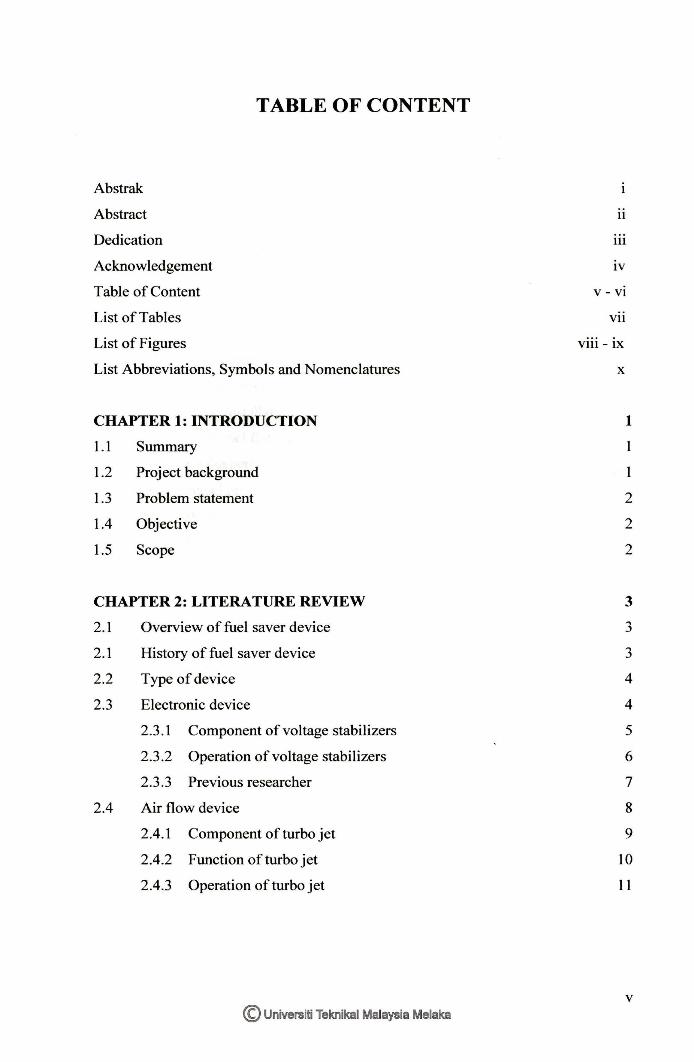
TABLE OF CONTENT
Abstrak
Abstract
Dedication
Acknowledgement
Table of Content
List of Tables
List of Figures
List Abbreviations, Symbols and Nomenclatures
CHAPTER 1: INTRODUCTION
1.1 Summary
1.2 Project background
1.3 Problem statement
1.4 Objective
1.5 Scope
CHAPTER 2: LITERATURE REVIEW
2.1
2.1
2.2
2.3
2.4
Overview of fuel saver device
History of fuel saver device
Type of device
Electronic device
2.3.1 Component of voltage stabilizers
2.3.2 Operation of voltage stabilizers
2.3.3 Previous researcher
Air flow device
2.4.1 Component of turbo jet
2.4.2 Function of turbo jet
2.4.3 Operation of turbo jet
© Universiti Teknikal Malaysia Melaka
11
Ill
lV
V - Vl
Vll
Vlll - lX
x
1
2
2
2
3
3
3
4
4
5
6
7
8
9
10
11
v
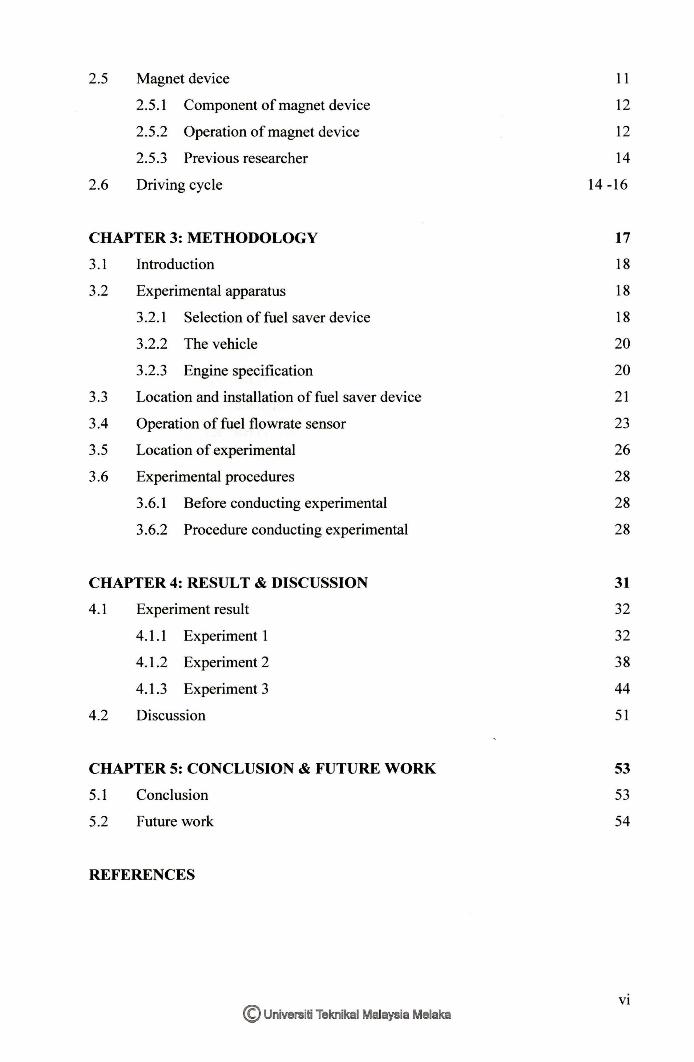
2.5 Magnet device
2.5.1 Component of magnet device
2.5.2 Operation of magnet device
2.5.3 Previous researcher
2.6 Driving cycle
CHAPTER3:METHODOLOGY
3.1 Introduction
3.2 Experimental apparatus
3.2.1 Selection of fuel saver device
3.2.2 The vehicle
3.2.3 Engine specification
3.3 Location and installation of fuel saver device
3.4 Operation of fuel flowrate sensor
3.5 Location of experimental
3.6 Experimental procedures
3.6.l Before conducting experimental
3.6.2 Procedure conducting experimental
CHAPTER 4: RESULT & DISCUSSION
4.1 Experiment result
4.1.1 Experiment 1
4.1.2 Experiment 2
4.1.3 Experiment 3
4.2 Discussion
CHAPTER 5: CONCLUSION & FUTURE WORK
5.1
5.2
Conclusion
Future work
REFERENCES
© Universiti Teknikal Malaysia Melaka
11
12
12
14
14 -16
17
18
18
18
20
20
21
23
26
28
28
28
31
32
32
38
44
51
53
53
54
VI
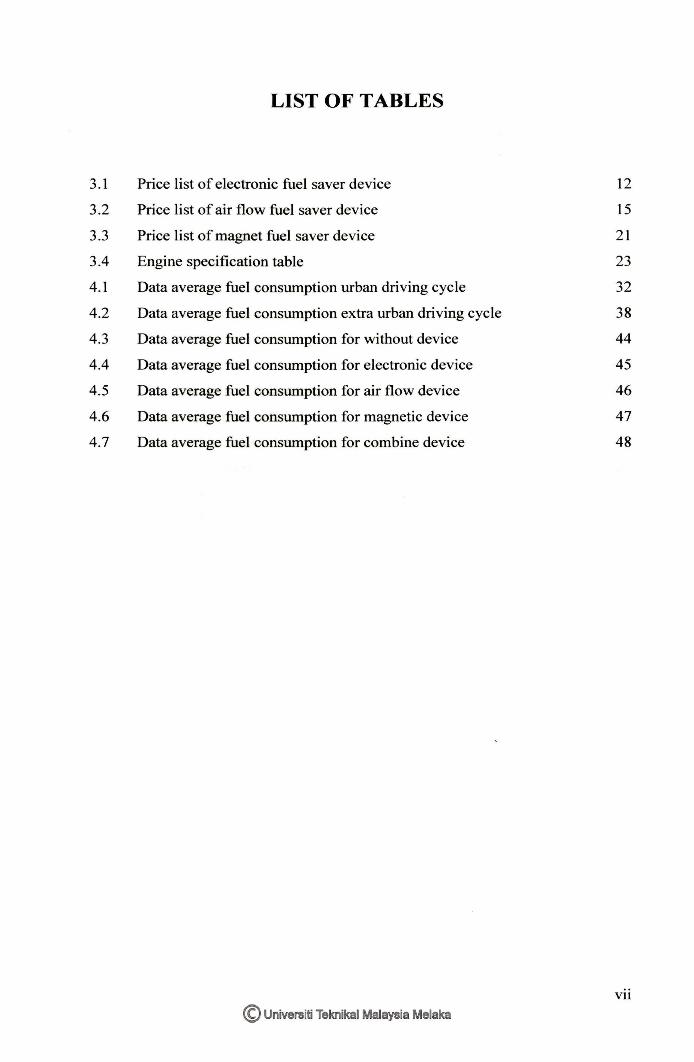
LIST OF TABLES
3.1 Price list of electronic fuel saver device 12
3.2 Price list of air flow fuel saver device 15
3.3 Price list of magnet fuel saver device 21
3.4 Engine specification table 23
4.1 Data average fuel consumption urban driving cycle 32
4.2 Data average fuel consumption extra urban driving cycle 38
4.3 Data average fuel consumption for without device 44
4.4 Data average fuel consumption for electronic device 45
4.5 Data average fuel consumption for air flow device 46
4.6 Data average fuel consumption for magnetic device 47
4.7 Data average fuel consumption for combine device 48
Vil
© Universiti Teknikal Malaysia Melaka
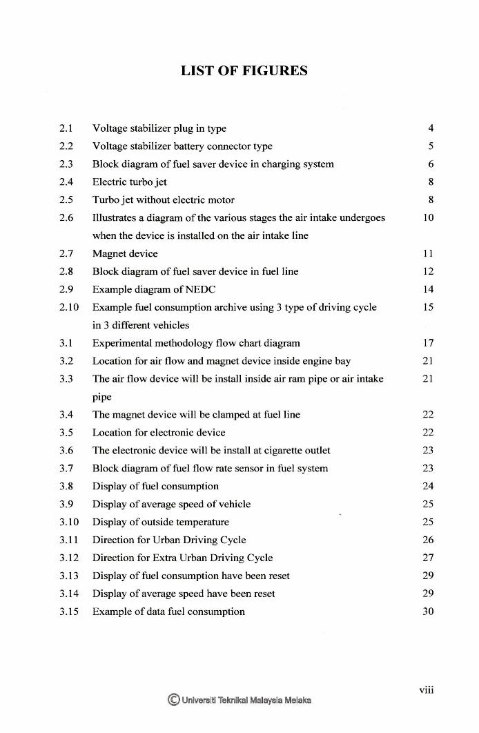
LIST OF FIGURES
2.1 Voltage stabilizer plug in type 4
2.2 Voltage stabilizer battery connector type 5
2.3 Block diagram of fuel saver device in charging system 6
2.4 Electric turbo jet 8
2.5 Turbo jet without electric motor 8
2.6 Illustrates a diagram of the various stages the air intake undergoes 10
when the device is installed on the air intake line
2.7 Magnet device 1 1
2.8 Block diagram of fuel saver device in fuel line 12
2.9 Example diagram ofNEDC 14
2.10 Example fuel consumption archive using 3 type of driving cycle 15
in 3 different vehicles
3.1 Experimental methodology flow chart diagram 17
3.2 Location for air flow and magnet device inside engine bay 21
3.3 The air flow device will be install inside air ram pipe or air intake 21
pipe
3.4 The magnet device will be clamped at fuel line 22
3.5 Location for electronic device 22
3.6 The electronic device will be install at cigarette outlet 23
3.7 Block diagram of fuel flow rate sensor in fuel system 23
3.8 Display of fuel consumption 24
3.9 Display of average speed of vehicle 25
3.10 Display of outside temperature 25
3.11 Direction for Urban Driving Cycle 26
3.12 Direction for Extra Urban Driving Cycle 27
3.13 Display of fuel consumption have been reset 29
3.14 Display of average speed have been reset 29
3.15 Example of data fuel consumption 30
© Universiti Teknikal Malaysia Melaka Vlll
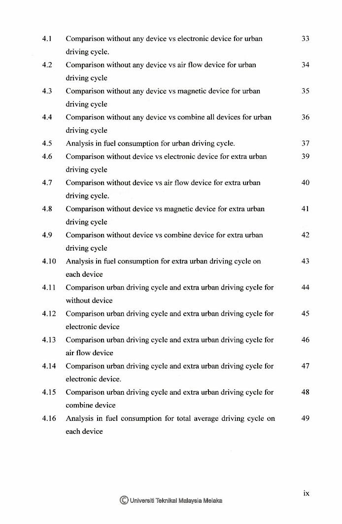
4.1 Comparison without any device vs electronic device for urban 33
driving cycle.
4.2 Comparison without any device vs air flow device for urban 34
driving cycle
4.3 Comparison without any device vs magnetic device for urban 35
driving cycle
4.4 Comparison without any device vs combine all devices for urban 36
driving cycle
4.5 Analysis in fuel consumption for urban driving cycle. 37
4.6 Comparison without device vs electronic device for extra urban 39
driving cycle
4.7 Comparison without device vs air flow device for extra urban 40
driving cycle.
4.8 Comparison without device vs magnetic device for extra urban 41
driving cycle
4.9 Comparison without device vs combine device for extra urban 42
driving cycle
4.10 Analysis in fuel consumption for extra urban driving cycle on 43
each device
4.11 Comparison urban driving cycle and extra urban driving cycle for 44
without device
4.12 Comparison urban driving cycle and extra urban driving cycle for 45
electronic device
4.13 Comparison urban driving cycle and extra urban driving cycle for 46
air flow device
4.14 Comparison urban driving cycle and extra urban driving cycle for 47
electronic device.
4.15 Comparison urban driving cycle and extra urban driving cycle for 48
combine device
4.16 Analysis in fuel consumption for total average driving cycle on 49
each device
© Universiti Teknikal Malaysia Melaka IX
NEDC
KM
L
AVG
DC
v RPM
ADC
FTP-75
EUDC
AT
RM
VVT-i
DOCH
DIS
ETCS-i
0
c m
UMNO
MBMB
psi
RON
kg
%
ECU
LIST OF ABBREVIATIONS, SYMBOLS AND
NOMENCLATURE
New European Driving Cycle
Kilometre
Litre
Average
Direct Current
Voltage
Rotation/Revolution Per Minute
Athens Driving Cycle
US Environment Protection Egency
Extra Urban Driving Cycle
Automatic Tranmission
Ringgit Malaysia
Variable Valve Timing-intelligent
Double Overhead Camshaft Head
Direct Ignition System
Electronic Throttle Control System-intelligent
Degree
Celsius
Metre
United Malays Nation Organization
Majlis Bandaraya Melaka Bersejarah
Pound Per Square Inch
Research Octane Number
Kilogram
Percent
Electronic Control Unit
© Universiti Teknikal Malaysia Melaka x
CHAPTERl
INTRODUCTION
As long as there are vehicles that use internal combustion engines, there is a
revolutionary device that promises improvements in performance and mileage. And
every time the fuel price hike, this device is growing like mushrooms after the rain.
According to dealer and testimony from customer that have use this device said to
get the significant and bigger reduction in fuel consumption, the vehicle should equip
more than one fuel saving device.
1.1 Project Background
At present, oil prices are unstable and this will further burden the lower class worker.
In this unstable situation, some people are trying to take advantage of the difficulties
of others such as selling useless items like fuel saving device. There are a variety of
fuel-saving devices such as electronic, magnet and air flow device in the current
market and according to the manufacturer claim, their fuel saving devices truly
effective in reducing fuel consumption and some dare to guarantee the device being
sold. Most of dealer and testimony from customer that have use this device said to
get the significant and bigger reduction in fuel consumption, the vehicle should be
equip more than one fuel saving device. If not get the desired results, the money will
be refunded.
© Universiti Teknikal Malaysia Melaka
1.2 Problem statement
From manufacturer advertisements, theirs simjlar claimed the voltage stabilizer,
magsaver and mini turbo fan can give high frequency impedance for more stable
voltage current to all electronic device, give a boost of air flow and also give a better
fuel ablaze. This will result in increased power, torque and improve fuel economy.
For this research the aim is only to investigation the effectives of this device on the
manufacturer claim of improving fuel economy. The effective for this device will be
validated after the experimental vehicle test with road testing. The analyze data and
results will approve or disapprove that the installation of this device will reduce the
fuel consumption.
1.3 Objective
The objective of this project is to validate the effectiveness of these fuel saver device
products by experimental method using actual road test at federal/city road and
highway road based on supplier and manufacturer's claims which states that their
product has impact on fuel saving usage.
1.4 Scope
The scope of this project is:-
(a) Determjne and compare with and without the use of each _fuel saver device on
vehicle.
(b) The experimental is conducted using Toyota Wish second generation (2013)
2ZR-FAE l.8L.
(c) The test is conducted at city road and highway using Driving cycle.
2 © Universiti Teknikal Malaysia Melaka
CHAPTER2
LITERATURE REVIEW
A case study on crude oil prediction at 2007 by Prof L. David Roper from Virginia
Polytechnic Institute and State University said, crude oil price prediction will
increase about 400 percent in 2020. This will lead about 30 percent increase price of
crude oil each year. With higher oil demand over the years, a variety of fuel-saving
devices have been created by the manufacturer to reduce fuel consumption on a
vehicle. This study is important because it will have a significant impact on daily
vehicle consumer.
2.1 History of fuel saver device
Fuel saver device already exist in early l 980' s when a company started by Mr. Joel
Robinson introduced a product called "The platinum fuel saver" in which device is
placed in vehicle vacuum line. This product claims that it can increase 22% of
overall gas mileage (platinum 22). Since then, there are many devices available today
that boast about saving gasoline and harnessing more miles per gallon by using their
product.
3 © Universiti Teknikal Malaysia Melaka
2.2 Type of device
There are many type of fuel saver device at the market today and most of device is to
optimize the ignition, fuel flow and air flow in engine system. This device usually is
easy to install at vehicle without cutting a wire or changing the part of engine. This
research is more on electronic device, air flow device and magnets device because
this entire device is more popular than other type and easy to install
2.3 Electronic device
Some of electronic devices is marketed as fuel saver and this device is the most
popular among the many types of fuel saving devices. This product also knows as
voltage stabilizers. This is because many types of electronic fuel saving device
requires no complicated installation in vehicles and easy to use. There are two
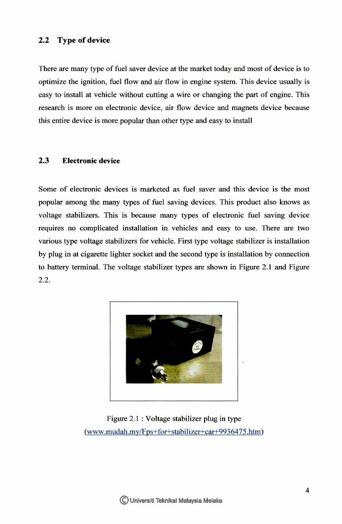
various type voltage stabilizers for vehicle. First type voltage stabilizer is installation
by plug in at cigarette lighter socket and the second type is installation by connection
to battery terminal. The voltage stabilizer types are shown in Figure 2.1 and Figure
2.2.
Figure 2.1 : Voltage stabilizer plug in type
(www.mudah.my/Fps+for+stabilizer+car+9936475.htm)
© Universiti Teknikal Malaysia Melaka
4
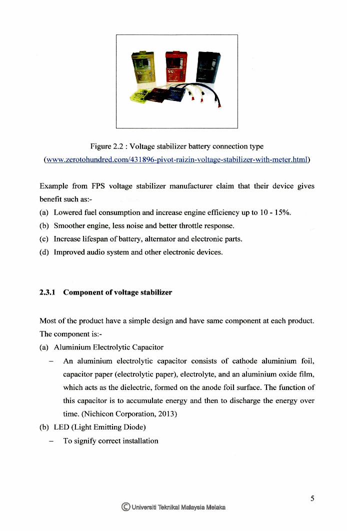
Figure 2.2 : Voltage stabilizer battery connection type
(www.zerotohundred.com/431896-pivot-raizin-voltage-stabilizer-with-meter.html)
Example from FPS voltage stabilizer manufacturer claim that their device gives
benefit such as:-
(a) Lowered fuel consumption and increase engine efficiency up to I 0 - 15%.
(b) Smoother engine, less noise and better throttle response.
( c) Increase lifespan of battery, alternator and electronic parts.
( d) Improved audio system and other electronic devices.
2.3.1 Component of voltage stabilizer
Most of the product have a simple design and have same component at each product.
The component is:-
( a) Aluminium Electrolytic Capacitor
An aluminium electrolytic capacitor consists of cathode aluminium foil ,
capacitor paper (electrolytic paper), electrolyte, and an aluminium oxide film,
which acts as the dielectric, formed on the anode foil surface. The function of
this capacitor is to accumulate energy and then to discharge the energy over
time. (Nichicon Corporation, 2013)
(b) LED (Light Emitting Diode)
To signify correct installation
5 © Universiti Teknikal Malaysia Melaka
( c) Replaceable fuse
Low resistance resistor that acts as a sacrificial device to provide overcurrent
protection of either the load or source circuit.
( d) Polyester capacitor
Paul Harden (n.d) state that polyester films use layers of metal and polyester
dielectric to make a wide range of capacitances in a relatively small package
at low voltages. These have become the standard caps for DC applications.
( e) Metal oxide varistor resistor
Varistor is polycrystalline ceramic devices exhibiting highly nonlinear
electrical behavior and greater energy absorption capability. The fabrication
of varistor is done by mixing semiconducting ZnO powder with other oxide
powders, and subjecting the powder mixture to conventional ceramic pressing
and sintering. The sintering results in a polycrystalline ceramic with grain
boundary property which produces the nonlinear current-voltage
characteristics of the device. When applied voltage exceeds rate clamping
voltage, the device effectively become short circuit and protecting the
component. (Thinking Electonic Industrial Co. LTD, 2012)
2.3.2 Operation of voltage stabilizer
12V Voltage Stabilizer
v 12¥ ... .. w
•!'I:*> ua!'u ,_,.,., s ~uo
- ~L ~ ~~~
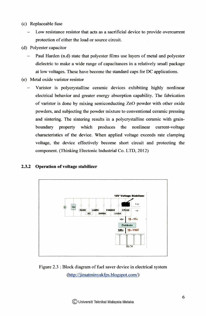
Figure 2.3 : Block diagram of fuel saver device in electrical system
(http://j imatminyakfus. blogspot.comL)
© Universiti Teknikal Malaysia Melaka 6
Before engine start, voltage stabilizer used the power source from battery,
combination of series and parallel of Aluminium Electrolytic Capacitor will case and
store energy. When ignition switch on, Aluminium Electrolytic Capacitor will
discharge output voltage. Polyster Capacitor will precision voltage rate not higher
than 14V and delivers the relatively constant voltage to measure by digital voltmeter
before transmitted voltage output to electrical load. Aluminium Electrolytic
Capacitor will case and discharge all overtime. When the input voltage from
alternator is lower than 14V, this device still deliver a constant output of 14V by
using restore current energy from Aluminium Electrolytic Capacitor. If the input
voltage higher that limit, Polyester Capacitor will close the circuit, store energy from
Aluminium Electrolytic Capacitor will discharge and the same time recharge
simultaneously using the surplus voltage from polyester capacitor. Metal Oxide
Varistor resistor will protect this system when voltage exceeds rated clamping
voltage; the device effectively becomes a short circuit. (Noor affandy, 2010)
2.3.3 Previous research of voltage stabilizer device
Noor affandy bin ahas, 2010. Studied on Experimental Validation Of Aftermarket
Fuel Saving Device (Voltage Stabilizer). The experiment was conduct using Nissan
Grand Livina 1.6L HRl 6DE 1.6 L with Automatic Transmission. The vehicle has
tested before and after the installation voltage stabilizer with Dynomax 2000 Chassis
Dynamometer for torque and power performance to determine its effects on fuel
economy. The results indicated that the voltage stabilizer device has increase of
torque performance about 1.4% begins at 2900 rpm and continuously to 6050 rpm.
However, there is no significant effect for the purpose of fuel saving and reducing
the cost of fuel consider the behaviour of driver and limit speed ofthis country.
7 © Universiti Teknikal Malaysia Melaka
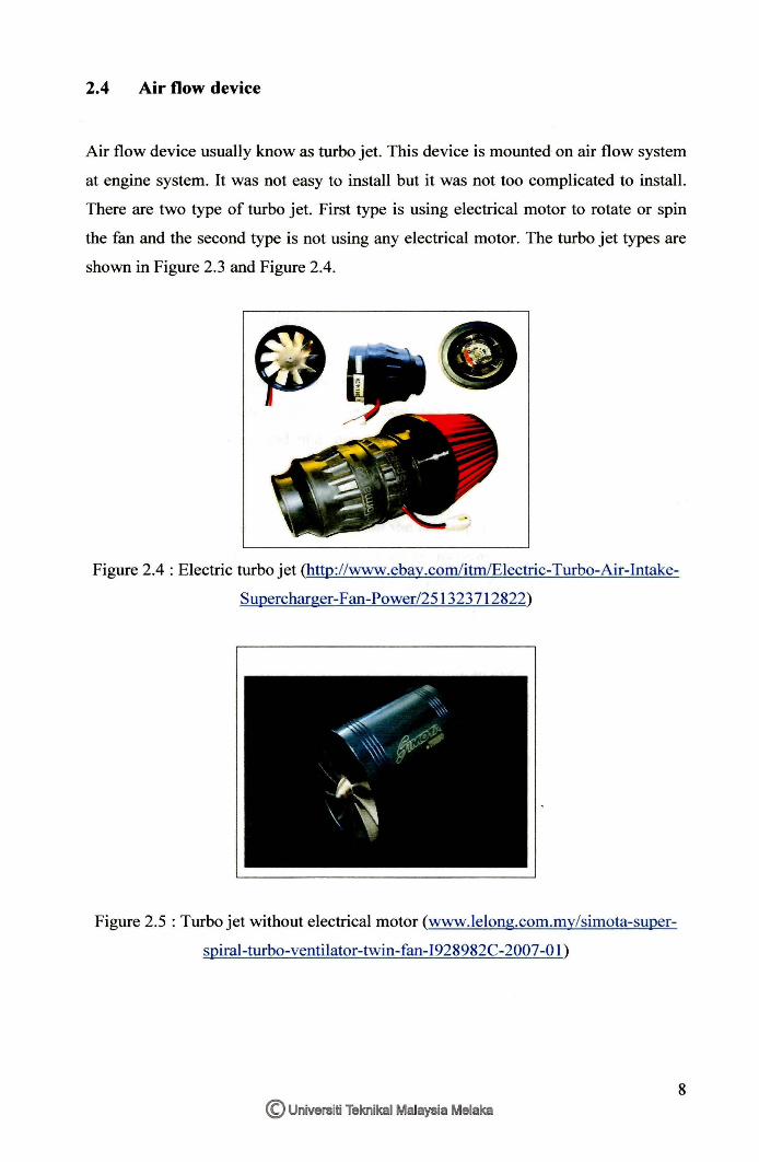
2.4 Air flow device
Air flow device usually know as turbo jet. This device is mounted on air flow system
at engine system. It was not easy to install but it was not too complicated to install.
There are two type of turbo jet. First type is using electrical motor to rotate or spin
the fan and the second type is not using any electrical motor. The turbo jet types are
shown in Figure 2.3 and Figure 2.4.
Figure 2.4 : Electric turbo jet (http://www.ebay.com/itm/Electric-Turbo-Air-Intake
Supercharger-Fan-Power/251323712822)
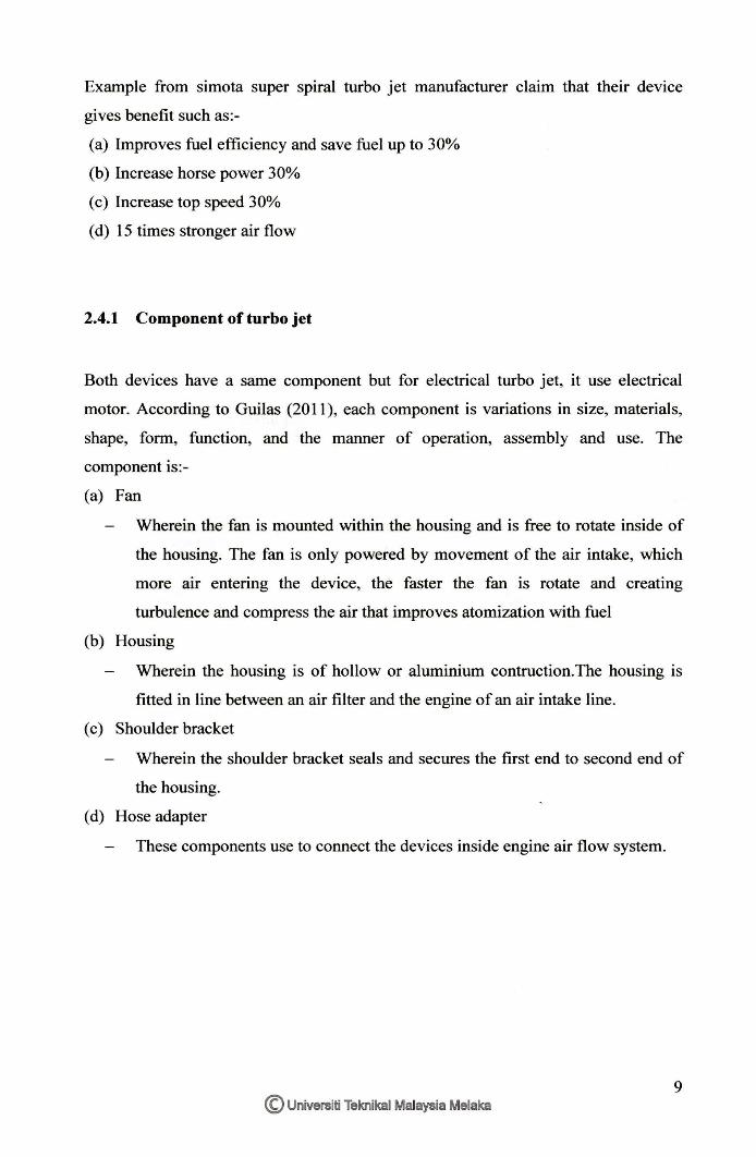
Figure 2.5 : Turbo jet without electrical motor (www.lelong.com.my/simota-super
spiral-turbo-ventilator-twin-fan-I928982C-2007-01 )
8 © Universiti Teknikal Malaysia Melaka
Example from simota super spiral turbo jet manufacturer claim that their device
gives benefit such as:-
(a) Improves fuel efficiency and save fuel up to 30%
(b) Increase horse power 30%
( c) Increase top speed 30%
( d) 15 times stronger air flow
2.4.1 Component of turbo jet
Both devices have a same component but for electrical turbo jet, it use electrical
motor. According to Guilas (2011), each component is variations in size, materials,
shape, form, function, and the manner of operation, assembly and use. The
component is:-
( a) Fan
Wherein the fan is mounted within the housing and is free to rotate inside of
the housing. The fan is only powered by movement of the air intake, which
more air entering the device, the faster the fan is rotate and creating
turbulence and compress the air that improves atomization with fuel
(b) Housing
Wherein the housing is of hollow or aluminium contruction.The housing is
fitted in line between an air filter and the engine of an air intake line.
( c) Shoulder bracket
Wherein the shoulder bracket seals and secures the first end to second end of
the housing.
( d) Hose adapter
These components use to connect the devices inside engine air flow system.
9 © Universiti Teknikal Malaysia Melaka
2.4.2 Function of turbo jet
The air intake accessory includes a housing containing a non-electric fan. The
housing has an inlet and outlet each of which connects between the air filter and
engine on the air intake line. The housing has a nozzle along the side of the fan
closest the air filter, which speeds up movement of the intake air. The inclusion of
the nozzle and non-electric fan improves fuel efficiency and engine performance.
(Guilas. M, 2011)
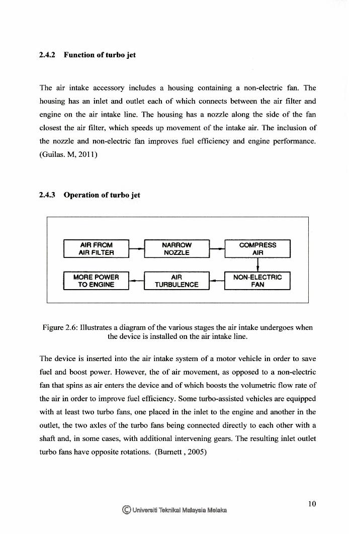
2.4.3 Operation of turbo jet
AIR FROM AIR FILTER
MORE POWER TO ENGINE
NARROW NOZZLE
AIR TURBULENCE
COMPRESS AIR
NON-ELECTRIC FAN
Figure 2.6: Illustrates a diagram of the various stages the air intake undergoes when the device is installed on the air intake line.
The device is inserted into the air intake system of a motor vehicle in order to save
fuel and boost power. However, the of air movement, as opposed to a non-electric
fan that spins as air enters the device and of which boosts the volumetric flow rate of
the air in order to improve fuel efficiency. Some turbo-assisted vehicles are equipped
with at least two turbo fans, one placed in the inlet to the engine and another in the
outlet, the two axles of the turbo fans being connected directly to each other with a
shaft and, in some cases, with additional intervening gears. The resulting inlet outlet
turbo fans have opposite rotations. (Burnett , 2005)
© Universiti Teknikal Malaysia Melaka IO