universiti teknikal malaysia melakaeprints.utem.edu.my/15182/1/activated carbon and... ·...
TRANSCRIPT
UNIVERSITI TEKNIKAL MALAYSIA MELAKA
ACTIVATED CARBON AND GRAPHENE BASED ELECTROCHEMICAL
CAPASITOR IN AQUEOUS ELECTROLYTE
This report submitted in accordance with requirement of the Universiti Teknikal Malaysia
Melaka (UTeM) for the Bachelor Degree of Manufacturing Engineering
(Engineering Materials)(Hons.)
by
NORASIMAH BINTI DORAH
B051010121
900515126096
FACULTY OF MANUFACTURING ENGINEERING
2014
DECLARATION
I hereby, declared this report entitled “Activated carbon and graphene based
electrochemical capacitor in aqueous electrolyte ” is the results of my own
research except as cited in references.
Signature : ………………………..
Author’s Name : Norasimah binti Dorah
Date : 23th
June 2014
APPROVAL
This report is submitted to the Faculty of Manufacturing Engineering of UTeM
as a partial fulfillment of the requirements for the degree of Bachelor of
Manufacturing Engineering (Engineering Material). The member of the
supervisory is as follow:
………………………………
(Dr Mohd Asyadi Azam bin Mohd Abid)
i
ABSTRAK
Laporan ini membincangkan tentang kapasitan satu kapasitor elektrokimia (SPR)
dengan menggunakan jenis yang sama bahan elektrod elektrolit tetapi berbeza.
Penggunaan elektrod dalam eksperimen ini diaktifkan karbon dicampur dengan
graphene. Terdapat dua elektrolit yang telah digunakan yang kalium hidroksida
(KOH) dan asid sulfurik (H2SO4). Fabrikasi satu EC meningkatkan permintaan
dalam penggunaan bateri dan kapasitor. Walau bagaimanapun, ketumpatan tenaga
yang rendah EC mengehadkan permohonannya. Oleh itu, penyelidik cuba untuk
membangunkan EC yang lebih baik dengan meningkatkan kawasan permukaan
mereka dengan menggunakan bahan berliang. Selain itu, kajian terdahulu mendapati
bahawa elektrolit yang berbeza memberi kesan yang kecil dalam kapasitan daripada
SPR. Kaedah yang digunakan dalam laporan ini adalah teknik keadaan pepejal.
Graphene itu melintang berorientasikan dan dengan itu menurunkan turun kemuatan
tertentu (Csp) nilai. Nilai kapasitan tertentu yang diperolehi daripada eksperimen
adalah 13 F g-1
dan 14 masing-masing F g-1
dalam KOH dan H2SO4 elektrolit.
ii
ABSTRACT
This report discuss about the capacitance of an electrochemical capacitor (EC) by
using same type of electrode material but different electrolyte. The electrode use in
this experiment is activated carbon mixed with graphene. There are two electrolytes
that are being use which are potassium hydroxide (KOH) and sulphuric acid
(H2SO4). The fabrication of an EC improves the demands in the usage of batteries
and capacitor. However, low energy density of EC limiting its application. Hence,
researchers try to develop a better EC by increasing their surface area by using a
porous material. Apart from that, previous researches found out that different
electrolytes give out small effect in the capacitance of an EC. The method used in
this report is solid state technique. The graphene was horizontally oriented and hence
lowering down the specific capacitance (Csp) value. The specific capacitance value
gained from the experiment was 13 F g-1
and 14 F g-1
in KOH and H2SO4 electrolytes
respectively.

iii
DEDICATION
This report is dedicated to my parents (Mr Dorah bin Tajallah and Mdm Minah binti
Amit) and my siblings (Mohd Asri, Hajmin, Mohd Romi, Lijawati, Norhasmi, Mohd
Hamdan, Mohd Nazri, and Mohd Arif).
I love you all.
iv
ACKNOWLEDGEMENT
I would like to offer my unreserved gratitude and praises to Almighty Allah for His
generous blessing and the undying strength bestowed upon me during the course of
this research.
Special thanks to my supervisor, Dr. Mohd Asyadi Azam bin Mohd Abid who guide,
assist and advise me all the way through this project.
Next, I want to thank my lovely parents whom with their prayers and moral support,
I have gained strength to endure in this study.
Thank you very much also to my mentors and friends especially to Elyas bin Talib,
Nor Syafira binti Abdul Manaf and Raja Noor Amalina binti Raja Seman.
Not forgotten, thank you to Tunku Ishak Tunku Kudin and Ainnur Sherene Kamisan
from iMADE Lab, UiTM Shah Alam for their technical support and guidance
throughout the experiment.
Last but not least, to the person who always there when needed, Malik Younis Omar
Kreishan, thank you so much.
v
TABLE OF CONTENT
Abstrak i
Abstract ii
Dedication iii
Acknowledgement iv
Table of Content v
List of Tables viii
List of Figures ix
List of Abbreviations, Symbols and Nomenclatures xi
CHAPTER 1: INTRODUCTION 1
1.1 Background 2
1.1.2 Energy storage devices 2
1.2 Problem Statement 5
1.3 Objectives 6
1.4 Scope of Project 6
vi
CHAPTER 2: LITERATURE REVIEW 7
2.1 Classification of electrochemical capacitor (EC) 7
2.2 Electrode materials 11
2.2.1 Electrochemical double layer capacitor (EDLC) 12
2.2.2 Pseudocapacitor 16
2.2.3 The composition of electrode materials 17
2.3 Electrolyte 18
2.3.1 Aqueous electrolyte 18
2.3.2 Non-aqueous electrolyte 19
2.4 Material Characterization 20
2.5 Energy dispersive x-ray (EDX) 21
2.6 Electrochemical performance 21
2.6.1 Cyclic voltammetry 21
CHAPTER 3: METHODOLOGY 23
3.1 Fabrication of carbon based EC 23
3.2 Electrode material preparation 24
3.2.1 Materials for EC fabrication 25
3.2.2 Equipment for EC fabrication 27
3.2.3 Experimental procedures 30
3.3 Fabrication process to produce EC 31
3.4 Set up for CV analysis 32
3.5 Flow chart 34
vii
3.6 Prototype development 35
CHAPTER 4: RESULT & DISCUSSION 37
4.1 EC fabrication process 37
4.2 Problem occurs in the experiment 41
4.2.1 Problem occurs in fabricating the electrodes 41
4.2.2 Problem occurs during testing the coin cell 42
4.3 Material characterization 43
4.4 Energy dispersive x-ray (EDX) performance 47
4.5 Electrochemical characterization 48
4.5.1 Performance of electrodes in 1M H2SO4 electrolyte 49
4.5.2 Performance of electrodes in 6M KOH electrolyte 52
CHAPTER 5: CONCLUSION & RECOMMENDATION 55
5.1 Conclusion 55
5.2 Recommendation 56
5.3 Future prospect 57
REFERENCES 58
GANTT CHART 62

viii
LIST OF TABLES
1.1 The differences between capacitor, electrochemical capacitor,
and battery
4
2.1 Properties of various electrolytes 19
2.3 The difference in CV, SEV and EV vulcanisation systems 28
3.1 Material and its function 25
3.2
3.3
Apparatus and its function
Materials used and its weight percentage
27
31
4.1 The compositions of electrode and its Csp value 38
4.2 The composition of materials that gave out the highest specific
capacitance value
39
ix
LIST OF FIGURES
1.1 Ragone plot of power density versus energy density 3
2.1 Schematic diagram of EDLC 8
2.3 Different types of capacitive charge storage mechanism 11
2.4 3D diagram of graphene, graphite, carbon nanotube and
buckminsterfullerene
13
2.5 Schematic diagram of the pore sizes network of an activated
carbon grain
14
2.6 SEM image of an activated carbon aerogel substrate prior to CNT
growth
20
2.7 Cyclic voltammetry curve of activated carbon 22
3.1 Schematic diagram of cross-sectional of an EC 24
3.2 Activated carbon powder and grapheme powder 24
3.3 Testing battery jig by using CV 32
3.4 Flow chart of methodology 34
3.5 Testing fabricated EC with LED light 35
x
3.6 Connected coin cell and LED in a larger amount 36
4.1
4.2
CV curve with different composition
Components of an EC
38
39
4.3 Corroded electrode 40
4.4 Slurry stuck in the mould 41
4.5 Coin cell burst open 42
4.6 The morphology of the electrode before (left) and after (right),
magnified into 500, 2000, and 5000x magnification
44
4.7 EDX graphs of electrode before and after immersed in the
electrolyte
46
4.8 CV curve of scan rate at 1mV/s in H2SO4 electrolyte 47
4.9 CV curve of scan rate at 1mV/s in H2SO4 electrolyte with
different cycles
49
4.10 CV curve of scan rate at 1mV/s in H2SO4 electrolyte with
different scan rate
50
4.11 CV curve of scan rate at 1mV/s in KOH electrolyte 51
4.12 CV curve of scan rate at 1mV/s in KOH electrolyte with different
scan rate
52
4.13 CV curve of activated carbon mixed with graphene in 6M KOH
with different scan rate
54
xi
LIST OF ABBREVIATIONS, SYMBOLS AND
NOMENCLATURE
AC - Activated carbon
C4H603 - Propylene carbonate
C2H3N - Acetonitrile
CV - Cyclic voltammetry
CNT - Carbon nanotube
Csp - Specific capacitance value
EC - Electrochemical capacitor
EDLC - Electrochemical double layer capacitor
EDX - Energy dispersive x-ray
G - Graphene
H2SO4 - Sulphuric acid
KOH - Potassium hydroxide
NMP - N-methylpyrrolidinone
OLC - Onion-like carbon
PF - Phenol-furfural
PVDF - Polyvinileidene difluoride
RF - Resorcinol-formaldehyde
SEM - Scanning electron microscop
1
CHAPTER 1
INTRODUCTION
This chapter discusses about the background and the different types of
electrochemical capacitor (ECs) that exist. The types of each energy storage device
are compared as long as its working mechanism which will be discussed in Chapter
2. The limitations of the batteries and conventional capacitors are brought upon and
the advantages of EC are being explained.
1.1 Background
Currently, energy has become a major focus in the scientific and industrial societies
due to climate change and fast development of the global economy. With the
increasing in environmental pollution and consumption of fossil fuel, there is high
demand to seek renewable and clean energy sources to ensure the sustainable
development of economies and societies (Azam, 2012). Alternatively, energy storage
devices such as batteries, fuel cells, and electrochemical capacitors (ECs) are being
used to store energy for various applications including mobile phones, laptops,
airplanes, buses, hybrid electric vehicles and etc. (Cary L. Pint, 2011). Recently, ECs
are considered as one of the most promising energy storage devices due to its high
rate performance, such as long life cycle and outstanding power density (Byungwoo
2
Kim, 2012). As for today, the three major commercialized energy storage devices are
capacitors, batteries and fuel cells. To illustrate the advantage of ECs, the structure,
mechanism and performance comparison of those devices are discussed in the
following sections of this chapter.
1.1.2 Energy storage devices
Basically, energy storage devices can be classified into three parts which are
Pconventional capacitors, ECs, and batteries. Conventional capacitors are defined as
fundamental electric circuit elements that store electrical energy in microfarads and
assist in filtering. It varies in terms of shape and size but possesses similar basic
configuration. Capacitor consists of two conductors carrying equal but opposite
charges. There are many important applications for capacitor in electronics field
including storing electric potential energy, delaying voltage changes when coupled
with resistors, filtering out unwanted frequency signals, forming resonant circuits
and making frequency dependent and independent voltage dividers when combined
with resistors.
Electrochemical capacitors (ECs) or supercapacitors work as energy storage devices
due to its high power densities and excellent cycling stability (Yuan, 2005). It
competes with another three energy storage devices which are conventional
capacitors, batteries and fuel cells. It also differs from conventional capacitors due to
its porous conductor of electrodes that comes from the same material for both
electrodes. These electrodes have huge surface area, and collect a large number of
charges in its thin layer of electrodes/electrolytes interface through electrostatic force
(EDLC) or non-faradic effect (pseudocapacitor), in order to possess a huge
capacitance (Yuan, 2005). Another type of EC is hybrid capacitor. Hybrid capacitor
combines the mechanism of a faradic and non-faradic electrode (Katsuhiko Naoi,
2013).
3
The working principle of batteries is based on the chemical separation. Due to this
principle, it possesses chemical reaction that limits its life cycles. Generally battery
consists of two unlike metals or conducting substances (electrodes) that are placed in
a liquid which causes a greater chemical change in one of the electrode than in the
other. Hence, an electrical pressure or electromotive force is caused to exist between
the two electrodes. The greater the difference in the chemical action on the
electrodes, the greater will be the electrical pressure. By connecting wires or any
electrical conductor to the terminals of the battery, an electric current will flow
through the path or circuit. As the current flows though the system, one or both
electrodes will undergo chemical changes and it will continue to flow until one or
both electrodes change entirely.
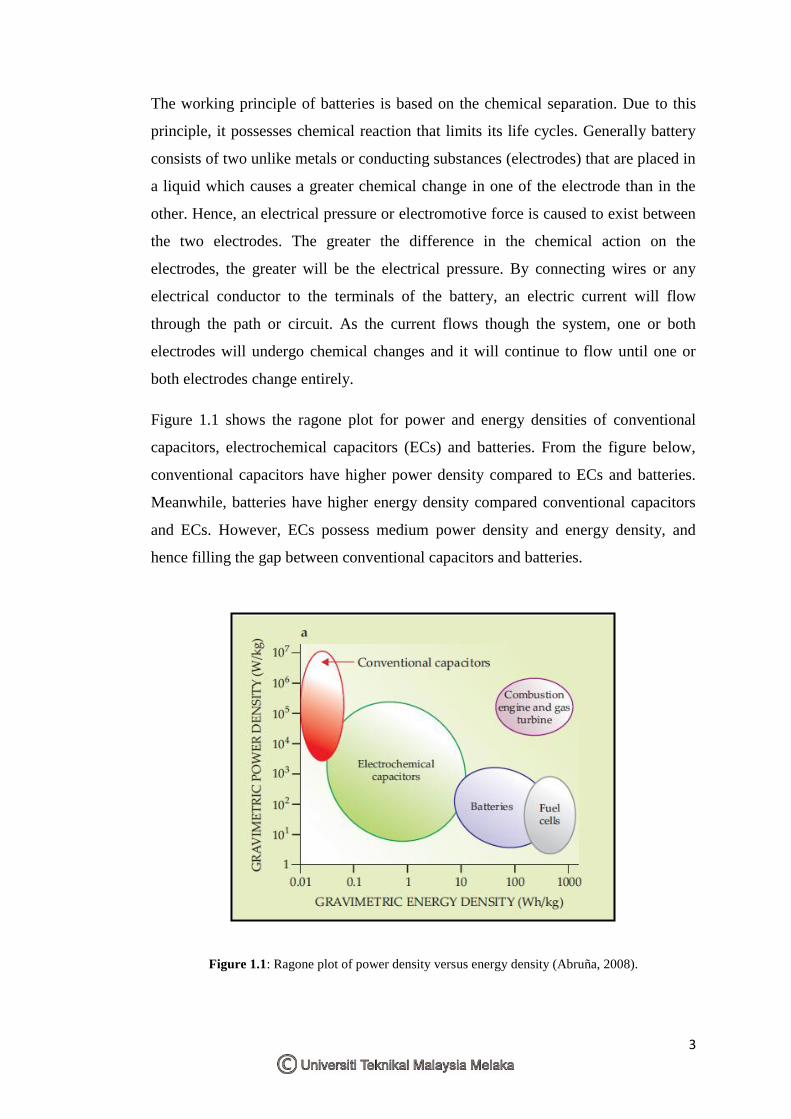
Figure 1.1 shows the ragone plot for power and energy densities of conventional
capacitors, electrochemical capacitors (ECs) and batteries. From the figure below,
conventional capacitors have higher power density compared to ECs and batteries.
Meanwhile, batteries have higher energy density compared conventional capacitors
and ECs. However, ECs possess medium power density and energy density, and
hence filling the gap between conventional capacitors and batteries.
Figure 1.1: Ragone plot of power density versus energy density (Abruña, 2008).
4
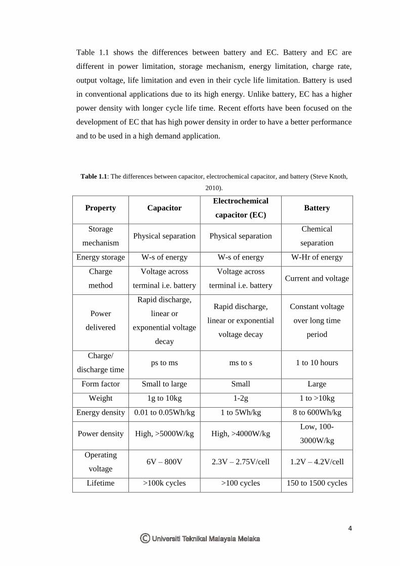
Table 1.1 shows the differences between battery and EC. Battery and EC are
different in power limitation, storage mechanism, energy limitation, charge rate,
output voltage, life limitation and even in their cycle life limitation. Battery is used
in conventional applications due to its high energy. Unlike battery, EC has a higher
power density with longer cycle life time. Recent efforts have been focused on the
development of EC that has high power density in order to have a better performance
and to be used in a high demand application.
Table 1.1: The differences between capacitor, electrochemical capacitor, and battery (Steve Knoth,
2010).
Property Capacitor Electrochemical
capacitor (EC) Battery
Storage
mechanism Physical separation Physical separation
Chemical
separation
Energy storage W-s of energy W-s of energy W-Hr of energy
Charge
method
Voltage across
terminal i.e. battery
Voltage across
terminal i.e. battery Current and voltage
Power
delivered
Rapid discharge,
linear or
exponential voltage
decay
Rapid discharge,
linear or exponential
voltage decay
Constant voltage
over long time
period
Charge/
discharge time ps to ms ms to s 1 to 10 hours
Form factor Small to large Small Large
Weight 1g to 10kg 1-2g 1 to >10kg
Energy density 0.01 to 0.05Wh/kg 1 to 5Wh/kg 8 to 600Wh/kg
Power density High, >5000W/kg High, >4000W/kg Low, 100-
3000W/kg
Operating
voltage 6V – 800V 2.3V – 2.75V/cell 1.2V – 4.2V/cell
Lifetime >100k cycles >100 cycles 150 to 1500 cycles
5
1.2 Problem statement
The study of conventional capacitors to replace batteries has been widely focused
into supercapacitosr which also known as ultracapacitors or in this study as
electrochemical capacitors (ECs). ECs possess remarkable property as it fills the gap
between conventional capacitors and batteries. Batteries have been used in
conventional application and conventional capacitors are applied on electronic
devices replacing batteries. However, the applications of conventional capacitors are
restricted by its low energy density. ECs have more power density than batteries but
low energy density. Hence, researchers are trying to overcome this problem by
varying the materials used as electrode to achieve a better performance. This study
will cover the effect of mixing activated carbon (AC) with graphene (G) as electrode
in two different aqueous electrolytes which are potassium hydroxide (KOH) and
sulphuric acid (H2SO4) on specific capacitance. In order to do so, basic
understanding of cyclic voltammetry (CV) is crucial. There are two parameters that
may affect the result obtained, which are the scan rate and voltage window. Apart
from that, CV will help to determine the type of EC whether it is electrochemical
double layer capacitor (EDLC) or pseudocapacitor.
6
1.3 Objective
The objectives of this research project are:
1. To fabricate the electrochemical capacitor by using activated carbon mixed
with graphene as electrode material in aqueous electrolytes.
2. To analyze the fabricated electrochemical capacitor by using cyclic
voltammetry (CV) analysis in aqueous electrolytes.
1.4 Scope
This experiment had used activated carbon and graphene as electrode and KOH and
H2SO4 as electrolyte. Note that 6M of KOH and 1M H2SO4 were used in this
experiment. Basically, this experiment will be focusing on the performance of EC
with two different electrolytes. This report will discuss about the activated carbon
and graphene, their applications and the importance of both in the electric device
field. The experiment was mostly done in the Material Laboratory, Faculty of
Manufacturing, University Teknikal Malaysia Melaka (UTeM). Fabrication of the
EC was done at UiTM Shah Alam before it was characterize in the material
laboratory UTeM. The electrochemical performance of working electrode, stainless
steel mesh coated with AC/G was evaluated using cyclic voltammetry to obtain a
desired gravimetric specific capacitance.

7
CHAPTER 2
LITERATURE REVIEW
This chapter discusses the three types of ECs that exist. The working principles of
each EC are also explained. Nonetheless, this topic is focusing more on EDLC and
the types of electrolyte that are being used in the experiment. Apart from that, the
material characterization and electrochemical performance that were used to test the
fabricated EC are also discussed in this chapter.
2.1 Classification of electrochemical capacitor (EC)
EC is divided into three; according to their energy storage modes to achieve
capacitance. Electrochemical double layer capacitor (EDLC) is known for its ions
polarization in which when a voltage is applied, current is generated due to the
rearrangement of charges. Pseudocapacitor in contrast, is popular with its faradic
processes and fast redox reaction that takes place at the electrode/electrolyte
interface due to change in oxidation state (Dar et al, 2013). EC has magnificient
power density ability compared to batteries. According to that fact, ECs can be put as
having good acceleration but poor range. From a viewpoint, ECs are a device with
excellent cycle life that can be used in a longer time but small in size compared to
the batteries (Scherson, 2006). The unit cell of an EC is based on its
8
electrode/electrolyte interface of high surface area (activated carbon). ECs stores
electrical energy like conventional capacitor which is based on the separation of the
positive and negative phase inside its interface.
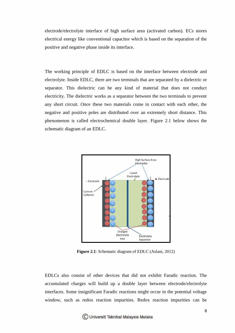
The working principle of EDLC is based on the interface between electrode and
electrolyte. Inside EDLC, there are two terminals that are separated by a dielectric or
separator. This dielectric can be any kind of material that does not conduct
electricity. The dielectric works as a separator between the two terminals to prevent
any short circuit. Once these two materials come in contact with each other, the
negative and positive poles are distributed over an extremely short distance. This
phenomenon is called electrochemical double layer. Figure 2.1 below shows the
schematic diagram of an EDLC.
Figure 2.1: Schematic diagram of EDLC (Aslani, 2012)
EDLCs also consist of other devices that did not exhibit Faradic reaction. The
accumulated charges will build up a double layer between electrode/electrolyte
interfaces. Some insignificant Faradic reactions might occur in the potential voltage
window, such as redox reaction impurities. Redox reaction impurities can be
9
considered as self-discharge reaction of EC. The effect of this insignificant reaction
is the accumulated charges cross the interface will be consumed in those reactions,
and the total amount of the charges in the double layer will decrease. Therefore, the
side reaction of Faradic that are mostly the redox impurities in the solution should be
avoided.
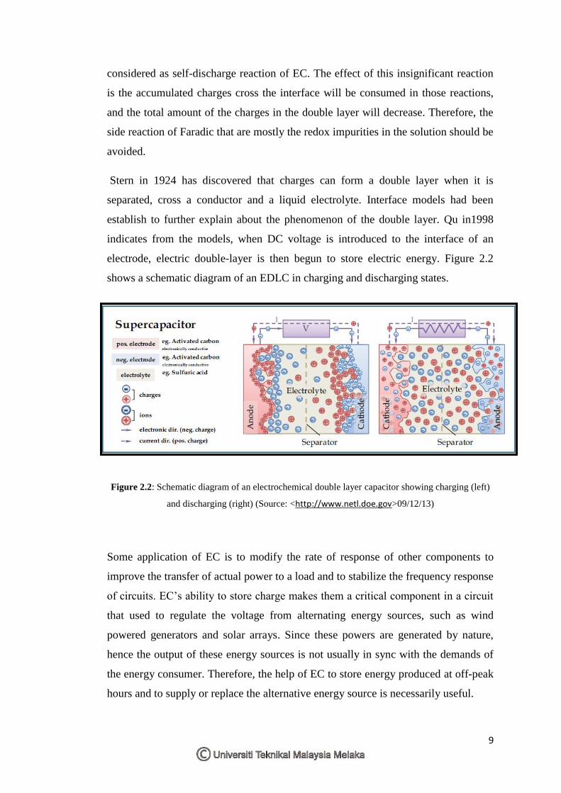
Stern in 1924 has discovered that charges can form a double layer when it is
separated, cross a conductor and a liquid electrolyte. Interface models had been
establish to further explain about the phenomenon of the double layer. Qu in1998
indicates from the models, when DC voltage is introduced to the interface of an
electrode, electric double-layer is then begun to store electric energy. Figure 2.2
shows a schematic diagram of an EDLC in charging and discharging states.
Figure 2.2: Schematic diagram of an electrochemical double layer capacitor showing charging (left)
and discharging (right) (Source: <http://www.netl.doe.gov>09/12/13)
Some application of EC is to modify the rate of response of other components to
improve the transfer of actual power to a load and to stabilize the frequency response
of circuits. EC’s ability to store charge makes them a critical component in a circuit
that used to regulate the voltage from alternating energy sources, such as wind
powered generators and solar arrays. Since these powers are generated by nature,
hence the output of these energy sources is not usually in sync with the demands of
the energy consumer. Therefore, the help of EC to store energy produced at off-peak
hours and to supply or replace the alternative energy source is necessarily useful.
10
The relationship between the amounts of energy stored (Q) in an EC, the voltage
applied (V) to drive the charge onto the plates of the EC, and the capacitance (C) is
given below;
Q=CV (Eq. 2.1)
Helmholtz explains that the capacitance per unit area of an EC is determined by the
distance between the parallel plates and the dielectric constant of a material between
the plates. These parameters can be translated into;
Eq. (2.2)
Where ɛr is the relative dielectric constant of the material between the plates, ɛo is the
vacuum permeability, A is the cross-sectional area of the plates, and d is the distance
between plates.
In contrast to EDLC where the charge is stored electrostatically at the interfaces of
the electrodes, pseudocapacitor stored charge through redox process at the electrodes
surface. This process originally comes from faradic process since it involves electron
transfer across the double layer at the electrode/electrolyte interfaces (John, 2009).
Pseudocapacitance is produced by the faradic charge transfer from species adsorbed
ineffective contact with the electrode surface or forming the electrode surface. The
charge storage possess by this mechanism is approximately one order of magnitude
higher than EDLC mechanism (Conway, 1999). However, when the electrostatic
stresses are produced by charge transfer and built up of charge on the surface, it will
lead to the mechanical strain within the electrode that will decrease the charge
storage capacity. Pseudocapacitors lose capacity much more rapidly than EDLC.
High charge and discharge rate also can produce extra stress that will shorter the
device lifetimes. In principle, pseudocapacitance is controlled by thermodynamics,
where the amount of charge accumulation (∆Q) from faradic charge transfer
processes which depends on the change in applied potential (∆V). Therefore,
pseudocapacitance corresponds to the derivative of ∆Q/∆V∙dQ/dV (John, 2009).
Figure 2.3 shows the working mechanism of EDLC and pseudocapacitor.