universiti putra malaysia application of …psasir.upm.edu.my/9042/1/fsas_2000_12_a.pdf ·...
TRANSCRIPT
UNIVERSITI PUTRA MALAYSIA
APPLICATION OF ELECTRICAL RESISTIVITY METHOD IN QUANTITATIVE ASSESSMENT OF GROUNDWATER
RESERVE OF UNCONFINED AQUIFER
HAGO ALI HAGO
FSAS 2000 12
APPLICATION OF ELECTRICAL RESISTIVITY METHOD IN QUANTITATIVE ASSESSMENT OF GROUNDWATER
RESERVE OF UNCONFINED AQUIFER
BY
HAGO ALI HAGO
Thesis Submitted in Fulfilment of Requirements for the Degree of Master of Science in the Faculty of Science and Environmental Studies
Universiti Putra Malaysia
January 2000

DEDICATED TO
The soul of my beloved brother Mohammed El Fadl EI Amin
in his falseless abode. Who was my true mentor in the
wisdom of his words and in the strength
of his protection. May Allah
accept him as a true
shahid.
11
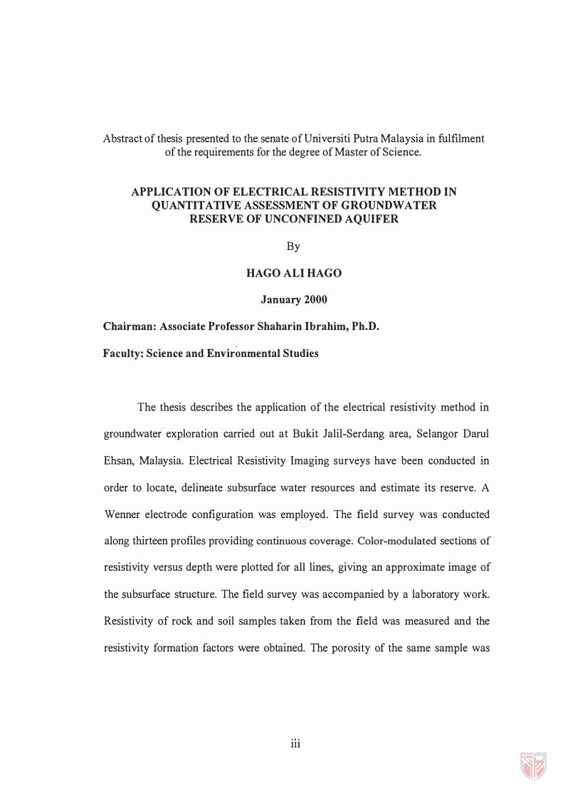
Abstract of thesis presented to the senate of Universiti Putra Malaysia in fulfilment of the requirements for the degree of Master of Science.
APPLICATION OF ELECTRICAL RESISTIVITY METHOD IN QUANTITATIVE ASSESSMENT OF GROUNDWATER
RESERVE OF UNCONFINED AQUIFER
By
HAGO ALI HAGO
January 2000
Chairman: Associate Professor Shaharin Ibrahim, Ph.D.
Faculty: Science and Environmental Studies
The thesis describes the application of the electrical resistivity method in
groundwater exploration carried out at Bukit Jalil�Serdang area, Selangor Darnl
Ehsan, Malaysia. Electrical Resistivity Imaging surveys have been conducted in
order to locate, delineate subsurface water resources and estimate its reserve. A
Wenner electrode configuration was employed. The field survey was conducted
along thirteen profiles providing continuous coverage. Color�modulated sections of
resistivity versus depth were plotted for all lines, giving an approximate image of
the subsurface structure. The field survey was accompanied by a laboratory work.
Resistivity of rock and soil samples taken from the field was measured and the
resistivity formation factors were obtained. The porosity of the same sample was
III
calculated. A relationship between the porosity and the formation factor has been
established. The laboratory established relationship was applied to the data
obtained in the field to calculate the porosity values of the formation present within
the investigated area. The porosity values were contoured and plotted. Depth to the
bedrock for each line was obtained. A 2-dimensional and 3-dimensional
representation of the subsurface topography of the area was prepared using a
commercial computer software. The use of the software also enabled the
computation of groundwater reserve within the investigated area.
The results showed that the layer associated with the aquifer has resistivities
between 20 Q.m and 150 Q.m and is located at a depth varying from 5 to 20m. The
layer has porosity between 18% and 35%. The results obtained from the electrical
resistivity profiles indicate that the aquifer occupies a surface area of about
15977900 m2 and has a mean depth of 13m, with net volume of 204610000 m3. The
average aquifer porosity is 30%. Therefore, a usable capacity of about 61,383,000 ±
6,752,130 m3 can be inferred.
lV
Abstrak tesis ini dikemukakan kepada Senat Universiti Putra Malaysia sebagai memenuhi keperluan untuk mendapatkan Ijazah Master Sains.
PENGGUNAAN KAEDAH KERINTANGAN ELEKTRIK DALAM PENINJAUAN SECARA KUANTITATIF SIMP AN AN AIR BA W AH
T ANAH UNTUK AKUIFER TERBUKA
Oleh
HAGO ALI HAGO
Januari 2000
Pengerusi: Profesor Madya Shaharin Ibrahim, Ph.D.
Fakulti: Sains dan Pengajian Alam Sekitar
Kajian ini menerangkan satu contoh penggunaan kaedah kerintangan
elektrik dalam eksplorasi air bawah tanah yang telah dijalankan dikawasan Bukit
Jalil-Serdang, di Negeri Selangor Darul Ehsan, Malaysia. Tinjauan pengimejan
kerintangan elektrik telah dijalankan untuk mengenalpasti lokasi dan memetakan
sumber air bawah tanah serta menganggarkan jumlah kandungan air yang terdapat
didalam sumber tersebut. Konfigurasi elektrod Wenner telah digunakan dalam
kaj ian ini. Kerja lapangan di sepanjang tiga belas profil telah dikendalikan. Keratan
rentas bermodulasikan warna bagi kerintangan bahan melawan kedalaman telah
diplot untuk semua profil yang menghasilkan imej bagi struktur dibawah tanah.
Kaj ian dimakmal juga telah dijalankan bersama-sama kajian dilapangan.
v
Kerintangan sampel batuan dan tanah telah diukur. Jumlah kandungan liang
rongga bagi sampel-sampel batuan dan tanah ini juga telah dikira. Daripada nilai
kerintangan ini, faktor formasi telah diperolehi. Satu hubungan antara jumlah
kandungan liang rongga dan faktor formasi telah diperolehi. Kaitan faktor formasi
kandungan liang rongga ini telah diaplikasikan keatas data-data kerintangan
elektrik yang diperolehi dari lapangan. Penggunaan kaitan ini telah menghasilkan
nilai keronggaan bagi formasi-formasi batuan dikawasan kaj ian.
Nilai-nilai jumlah kandungan liang rongga telah dikontur dan diplotkan.
Kedalaman batuan desar di bawah tiap-tiap geris rentasan telah diperolehi. Satu
gambaran 2-dimensi dan 3-dimensi topografi permukaan batuan dasar telah
disediakan dengan menggunakan perisian komersial. Penggunaan perisian ini juga
telah membolehkan pengiraan jumlah kandungan air tanah yang terdapat di
kawasan kajian.
Keputusan menunjukkan lapisan pada akuifer memiliki kerintangan di
antara 20 n.m dan 1 50 n.m dan berada pada kedalaman yang di antara 5 hingga
20 m. Lapisan ini mempunyai jumlah kandungan liang rongga di antara 1 8% dan
35%. Keputusan daripada profil kerintangan elektrik menunjukkan, akuifer yang
dikaji meliputi kawasan permukaan seluas 1 5,977,900 m2 dan memiliki purata
VI

kedalaman 1 3 m dari permukaan dengan isipadu bersih 204,61 0,000 m3. Purata
jumlah liang rongga bagi akuifer ialah 30%. Oleh itu kapasiti penggunaan
6 1 ,3 83,000 ± 6,752, 1 30m3 boleh diperolehi.
Vll

ACKNOWLEDGMENTS
Firstly Praise be to Allah for giving me the strength and patience to
complete this work and Peace be upon his final Prophet and Messenger
Mohammed. My full thanks to associate professor, Dr. Shaharin bin Ibrahim,
chairman of my supervisory committee, for his useful discussions, invaluable
suggestions, unlimited assistance, beneficial advice and continuous encouragement
through out this work. I have the highest regard for his professional courtesy and
the profound humility of his character.
Similar thanks must go to members of my supervisory committee, associate
professor Dr. Wan Nor Azmin bin Sulaiman and associate professor, Dr. Mohd
Kamil bin Yusoff, for taking interest in and offering helpful suggestions and
guidance.
I would like to thank members and staff in the department of physics who
have always willing to offer assistance, in particular, Mr. Mohd Shah Ibrahim, Mr.
Roslim Mohd, Mr. Nordin Abdul Kadir and Mr. Razak Harun. I would like to take
this opportunity to express my thanks to my friends who have helped me in this
work: Mr. Ugantharan Maruthaveeran, Mr. Abdelatif Mukhtar, Mr. Elrashied Imam
Elkhidir and Mr. Elsadig Eljack.
viii

Higher Education Ministry (Sudan) and Malaysian Technical Corporation
program (MTCP) which is highly appreciated and gratefully acknowledged
provided financial support. May Allah reward my supervisor and committee for
their dedication and service to humankind.
ix
I certify that an Examination Committee met on January 27, 2000, to conduct the final examination of Hago Ali Hago Ali, on his Master of Science thesis entitled "Application of Electrical Resistivity Method in Quantitative Assessment of Groundwater Reserve of Unconfined Aquifer" in accordance with Universiti Pertanian Malaysia (Higher Degree) Act 1 980 and Universiti Pertanian Malaysia (Higher Degree) Regulation 1 98 1 . The Committee recommends that the candidate be awarded the relevant degree. Members of the Examination Committee are as follows:
PAUZIAH ABD. LATIF, Ph.D. Lecturer, Department of Environmental Studies Faculty of Science and Environmental Studies Universiti Putra Malaysia (Chairman)
SHAHARIN IBRAHIM, Ph.D. Associate Professor, Physics Department Faculty of Science and Environmental Studies Universiti Putra Malaysia (Member)
MOHD KAMIL YUSOFF, Ph.D. Associate Professor, Department of Environmental Studies Faculty of Science and Environmental Studies Universiti Putra Malaysia (Member)
WAN NOR AZMIN SULAIMAN, Ph.D. Lecturer, Department of Environmental Studies Faculty of Science and Environmental Studies Universiti Putra Malaysia (Member)
----------�--�----------------------
HAZALI MOHA YIDIN, Ph.D. Professor !Deputy Dean of Graduate School Universiti Putra Malaysia
Date: � � FE'B 2000
x
This thesis was submitted to the Senate of Universiti Putra Malaysia and was accepted as fulfillment of the requirements for the degree of Master of Science.
Xl
KAMIS XWAN(i,ih.D. Associate Professor Dean of Graduate School Universiti Putra Malaysia
Date:1 1 MAY 2000
DECLARATION
I hereby declare that the thesis is based on my original work except for quotations and citations, which have been duly acknowledged. I also declare that it has not been previously or concurrently submitted for any other degree at UPM or other institutions.
xu
Hago Ali Hago Ali
Date: Q Lt / 2 } 2o�o
TABLE OF CONTENTS
Page
DEDICATION. . . . . . . . . . . . . . . . . . . . . . . . . . . . . . . . . . . . . . . . . . . . . . . . . . . . . . . . . . . . . . . . . . . . . . . . . . . . ii ABSTRACT. . . . . . . . . . . . . . . . . . . . . . . . . . . . . . . . . . . . . . . . . . . . . . . . . . . . . . . . . . . . . . . . . . . . . . . . . . . . . . . iii ABSTRAK. . . . . . . . . . . . . . . . . . . . . . . . . . . . . . . . . . . . . . . . . . . . . . . . . . . . . . . . . . . . . . . . . . . . . . . . . . . . . . . . . v ACKNOWLEDGEMENTS. . . . . . . . . . . . . . . . . . . . . . . . . . . . . . . . . . . . . . . . . . . . . . . . . . . . . . . . . . . . viii APPROVAL SHEETS. . . . . . . . . . . . . . . . . . . . . . . . . . . . . . . . . . . . . . . . . . . . . . . . . . . . . . . . . . . . . . . . . . x DECLARATION FORM. . . . . . . . . . . . . . . . . . . . . . . . . . . . . . . . . . . . . . . . . . . . . . . . . . . . . . . . . . . . . . . xii LIST OF TABLES. . . . . . . . . . . . . . . . . . . . . . . . . . . . . . . . . . . . . . . . . . . . . . . . . . . . . . . . . . . . . . . . . . . . . . . xvii LIST OF FIGURES. . . . . . . . . . . . . . . . . . . . . . . . . . . . . . . . . . . . . . . . . . . . . . . . . . . . . . . . . . . . . . . . . . . . . xix
CHAPTER
I INTRODUCTION . . . . . . . . . . . . . . . . . . . . . . . . . . . . . . . . . . . . . . . . . . . . . . . . . . . . . Previous Work in the Study Area . . . . . . . . . . . . . . . . . . . . . . . . . . . . . . . . . . . . . Objectives of the Present Study . . . . . . . . . . . . . . . . . . . . . . . . . . . . . . . . . . . . . . . The Study Area . . . . . . . . . . . . . . . . . . . . . . . . . . . . . . . . . . . . . . . . . . . . . . . . . . . . . . . . . .
Drainage . . . . . . . . . . . . . . . . . . . . . . . . . . . . . . . . . . . . . . , . . . . . . . . . . . . . . . . . . Topography . . . . . . . . . . . . . . . . . . . . . . . . . . . . . . . . . . . . . . . . . . . . . . . . . . . . . . Climate . . . . . . . . . . . . . . . . . . . . . . . . . . . . . . . . . . . . . . . . . . . . . . . . . . . . . . . . . . . Vegetation . . . . . . . . . . . . . . . . . . . . . . . . . . . . . . . . . . . . . . . . . . . . . . . . . . . . . . .
Layout of the Thesis . . . . . . . . . . . . . . . . . . . . . . . . . . . . . . . . . . . . . . . . . . . . . . . . . . . . .
II LITERATURE REVIEW . . . . . . . . . . . . . . . . . . . . . . . . . . . . . . . . . . . . . . . . . . . . Introduction . . . . . . . . . . . . . . . . . . . . . . . . . . . . . . . . . . . . . . . . . . . . . . . . . . . . . . . . . . . . . . . Role of Geophysics in Groundwater Prospecting and Hydrogeology . . . . . . . . . . . . . . . . . . . . . . . . . . . . . . . . . . . . . . . . . . . . . . . . . . . . . . . The Use of the Resistivity Method in Groundwater Prospecting . . . . . . . . . . . . . . . . . . . . . . . . . . . . . . . . . . . . . . . . . . . . . . . . . . . . . . . . . . . . . . . .
III GEOLOGY OF THE STUDY AREA . . . . . . . . . . . . . . . . . . . . . . . . . . . . . . Introduction . . . . . . . . . . . . . . . . . . . . . . . . . . . . . . . . . . . . . . . . . . . . . . . . . . . . . . . . . . . . . . Kenny Hill Formation . . . . . . . . . . . . . . . . . . . . . . . . . . . . . . . . . . . . . . . . . . . . . . . . . . .
Occurrence . . . . . . . . . . . . . . . . . . . . . . . . . . . . . . . . . . . . . . . . . . . . . . . . . . . . . . Lithology . . . . . . . . . . . . . . . . . . . . . . . . . . . . . . . . . . . . . . . . . . . . . . . . . . . . . . . . . Structure . . . . . . . . . . . . . . . . . . . . . . . . . . . . . . . . . . . . . . . . . . . . . . . . . . . . . . . . . Fossils and Age . . . . . . . . . . . . . . . . . . . . . . .. . . . . . . . . . . . . . . . . . . . . . . . . . Origin of Sediments . . . . . . . . . . . . . . . . . . . . . . . . . . . . . . . . . . . . . . . . . . . . Tectonic History . . . . . . . . . . . . . . . . . . . . . . . . . . . . . . . . . . . . . . . . . . . . . . . .
VI METHODS OF INVESTIGATIONS . . . . . . . . . . . . . . . . . . . . . . . . . . . . . . . . . . Introduction . . . . . . . . . . . . . . . . . . . . . . . . . . . . . . . . . . . . . . . . . . . . . . . . . . . . . . . . . . . . . . . . . . . Traditional Resistivity Surveys . . . . . . . . . . . . . . . . . . . . . . . . . . . . . . . . . . . . . . . . . . . . .
Xlll
1 3
3
4
5
6
6
7
7
9
9
10
16
35
35
37
37
38
41
42
44
46
48
48
49
v
The Relationship between Geology and Resistivity . . . . . . . . . . . . . . . .. 52
Earth Resistivity Method. . . . . . . . . . . . . . . . . . . . . . . . ... ................. .... 54
Electrode Configuration used. . . . . . . . . . . . . . . . . . . . . . . . . . . . . . . . . . . . . . . . . . 58
Wenner Configuration . . .. . . . ,. ... ......... ...... ......... ...... 58
2-D Electrical Imaging Surveys. . . . . . . . . . . . . . . . . . . . . . . . . . . . . . . . . . . . . . . 59
Introduction. . . . . . . . . . . . . . . . . . . . . . . . . . . . . . . . . . . . . . . . . . . . . . . . . . . ... 59
Field Survey Method. . . . . . . . . . . . . . . . . . . . . . . . . . . . . . . . . . . . . . . . . . . 62
Pseudosection Data Plotting Method. . . . . . . . . . . . . . . . . . . . . . . . ...... ... 65
The Advantages and Disadvantages of the Different Arrays . . . . . . 67
Wenner Array . . . . . . . . . . . . . . . . . . . . . . . . . . . . . . . . . . . . . . . . . . . . . . . ..... 7 1
Dipole-Dipole Array .............. , .................. ... ... .... 72
Schlumberger Array .. . . . . . . . . . . . . . . . . . . . . . . . . . . . . . . . . . . . . . . . ... 73
Summary. . . . . . . . . . . . . . . . . . . . . . . . . . . . . . . . . . . . . . . . . . . . . . . . . . . . . . . . . . . . . . . . . 74
Interpretation of Resistivity Field Data with the Aid of Computer. . . . . . . . . . . . . . . . . . . . . .............................. 74
Contouring of Porosity Values . . . . . . . . . . . . . . . . . . . . . ... ............ 76
LABORATORY DETERMINATIONS OF PETROPHYSICAL PROPERTIES . . . . . . . . . . . . . . . . . . . . . . . . . . . . . . . Introduction . . . . . . . . . . . . . . . . . . . . . . . . . . . . . . . . . . . . . . . . . . . . . . . . . . . . . . . . . . . . .. Total Porosity and Effective Porosity . . . . . . . . . . . . . . . . . . . . . . . . . . . . . . ..
Total or Absolute Porosity . . . . . . . . . . . . . . . . . . . . . . . . . . . . . . . . . . .. Effective Porosity . . . . . . . . . . . . . . . . . . . . . . . . . . . . . . . . . . . . . . . . . . . . . .
Rocks and their Porosity . . . . . . . . . . . . . . . . . . . . . . . . . . . . . . . . . . . . . . . . . . . . . "
Determinations of Effective Porosity of the Core Samples . . . . . . . Introduction . . . . . . . . . . . . . . . . . . . . . . . . . . . . . . . . . . . . . . . . . . . . . . . . . . . . .. Methodology . . . . . . . . . . . . . . . . . . . . . . . . . . . . . . . . . . . . . . . . . . . . . . . . . . . .
Selection and Preparation of Samples . . . . . . . . . . . . ' "
Cleaning of Samples . . . . . . . . . . . . . . . . . . . . . . . . . . . . . . . . . . . Drying of Samples . . . . . . . . . . . . . . . . . . . . . . . . . . . . . . . . . . . , . Weighing of Samples and Volume Determination Saturation of Samples . . . . . . . . . . . . . . . . . . . . . . . . . . . . . . . . .
Calculations of Effective Porosity . . . . . . . . . . . . . . . . . . . . . . . . ' "
Determinations of Hydraulic Conductivity of the Core Samples . . . . . . . . . . . . . . . . . . . . . . . . . . . . . . . . . . . . . . . . . . . . . . . . . . . . . . . . . . . .
Introduction . . . . . . . . . . . . . . . . . . . . . . . . . . . . . . . . . . , . . . . . . . . . . . . . . . . . . Darcy's Law . . . . . . . . . . . . . . . . . . . . . . . . . . . . . . . . . . . . . . . . . . . . . . . . . . . . . . . . . . . .
Permeability . . . . . . . . . . . . . . . . . . . . . . . . . . . . . . . . . . . . . . . . . . . . . . . . . . . . Determinations of Hydraulic Conductivity . . . . . . . . . . . . . . . . . . . . . . . . .
Laboratory Methods . . . . . . . . . . . . . . . . . . . . . . . . . . . . . . . . . . . . . . . . . . . Equation for the Determination of Hydraulic Conductivity of a Rock Specimen by the Falling Head Method . . . . . . . . . . . . . . . . . . . . . . . . . . . . . . . . . . . . . . . . . . . . . . . . . . . .
D t . .
f EI .
I R . . .
e ermmatlOn 0 ectnca eSlstlvlty . . . . . . . . . . . . . . . . . . . . . . . . . . . . . .
XIV
78
78
79
79
80
80
81
81
82
82
82
83
83
84
84
85
85
86
86
88
88
90
94
VI
Introduction. . . . . . . . . . . . . . . . . . . . . . . . . . . . . . . . . . . . . . . . . . . . . . . . . . . ... 94
Methodology. . . . . . . . . . . . . . . . . . . . . . . . . . . . . . . . . . . . . . . . . . . . . . . . . . .. 95
Preparation of Core Samples. . . . . . . . . . . . . . . .. . . . . . . ... 95
Sample Drying . . . . . . . . . . . . ... . . . . . . . .... . . . , ...... ... ... 95
Samples Saturation with Electrolyte Solution. . . ... 96
Measurements of Resistivity. . . . . . . . . . . . . . . . . . . . . . . . . . . . . . . . . 97
Formation Factor. . . . . . . . . . . . . . . . . . . . . . . . . . . . . . . . . . . . . . . . . . . . . . . . .. . . . . . . 99
Methods of Calculation. . . .. . . . . . . . .. . . . . ............... ... .... 99
Measurements of Parameters on Soil Samples. ...... . . . . . . . . .... . . 101
Porosity. . .... . . . ..... . . . . . . . . . . . . . .. . ... . . . . .. . . . . . ... . . . . ... . . .. 101
Hydraulic Conductivity. . ....... ........... .. .......... ........ 103
RESULTS AND DISCUSSION . . . . . . . . .. . . . . . . . . . . . . . . . . . . . . . . . . . . . Introduction ..... .. . . ....... . . . . . . . . . . .... . . .. . . . . . . . . ..... . . . . . ... .. . . . . .
Laboratory Work .... . . . . . . .... . . . . . . . . . . . .. . . . .. . . . . , . . . . . . . . . . .. .. . . . . . . Effective Porosity .. . . . . . . . .. . . . . . ... . . . . . .. .. . . . . . .. . . . . ... ... . The Variation of Electrical Resistivity, Formation Factor and Fractional Porosity of Earth Materials from the Study Area . .. . . . . .. . .. .. . .. . . . . . .. . . . .. . ... .. . ... .. . . Hydraulic Conductivity ... . . . . . . . . . . . . .... .. . . . . .. . . . . . . . . . . . .
2 Dimensional Electrical Resistivity Imaging . . . . .. . . . ... . . . . . ... . . Bukit Jalil Line 1 . . . . . . . . . . . . . . . . . . . . . . . . . . . . . . . . . . . . . . . . . . . . . . . Bukit Jalil Line 2 .............................................. . Bukit Jalil Line 3 . . . . . . . . . . . . . . . . . . . . . . . . . . . . . . . . . . . . . . . . . . . . . . . Bukit Jalil Line 4 ............................................. .. Bukit Jalil Line 7 . . . . . . . . . . . . . . . . . . . . . . . . . . . . . . . . . . . . . . . . . . . . . . . Bukit Jalil Line 5 . . . . . . . . . . . . . . . . . . . . . . . . . . . . . . . . . . . . . . . . . . . . . .. Bukit Jalil Line 6 . . . . . . . . . . . . . . . . . . . . . . . . . . . . . . . . . . . . . . . . . . . . . . . Bukit Jalil Line 8 . . . . . . . . . . . . . . . . . . . . . . . . .. . . . . . . . . . . .. . . . . . . . .. ApmLine . . . . . . ....... . . . . . .. . . .. . . .. . .. . . . . ... . .. . .. . . . . . .... . Taman Uninersity Line . . . . . . . . . ... .. . . . . .. . ... . . . .. . . .. . ... .. Mardi Line 1 . . . . . . . . . . . . . . . . . . . . . . . . . . . . . . . . . . ... . . . . . . . . . . . . . . . Mardi Line 2 . . . . . . . . . . . . . . . . . . . . . . . . . . . . . . . . . . . . . . . . . . . . . . . . . . . .
Mardi Line 3 ........ .. ........ ..... . . . . ....... . . .. . . . . . . . .. . ... . Porosity Distribution .. . ..... . . ... . . ..... . . . . . . .. . . ... . . . ... . . . ... . . ... .
Porosity Distribution along Electrical Resistivity Imaging Lines . . . ... . . . . . . ... . . . . . . . . . ... . .. . . . .. . . . .. . . . . . .. . . .. . . ... . ..
Bukit Jalil Line 1 . . . . . . . . . . . . . . . . . . . . . . . . . . . . . . . . . . . . . . . . . . . . . . . Bukit Jalil Line 2 . . . . . . . . . . . . .. . . . . . . . . . . . . .. . . . . . . . . .. . . . . . . . .. Bukit Jalil Line 3 . . . . . .. ... . . .. . . .. .... . . . . . . . ... . . .. . . . . . . . . . .. Bukit Jalil Line 4 ............................................. ..
Bukit Jalil Line 7 . . . .. .. . . . . . .. . .. . . .. . . . . . . . . . . . . .. , . . . . .. . . .. .
Bukit Jalil Line 5 . . . . . . . . . . . . . . . . . . . . . . . . . . . . . . . . . . . . . . . . . . . . . ..
xv
105
105
106
106
107
114
118
118
120
121
122
123
124
125
126
127
128
129
130
131
132
135
135
136
137
138
139
140
VII
Bukit Jalil Line 6 . . . . . . . . . . . . . . . . . . . . .. . . . . . . . . . . . . . . . . . . . . . . . . . 141
Bukit Jalil Line 8 . . . . . . . . . . . . . . . . . . . . . . . . . . . . . . . . . . . . . . . . . . . . . . . 142
Apm Line . . . . . . . . . . . . . . . . . . . . . . . . . . . . . . . . . . . . . . . . . . . . . . . . . . . . . . 143
Taman University Line . . . . . . . . . . . . . . . . . . . . . . . . . . . . . . . . . . . . ... 144
Mardi Line 1............. ...... ...... . . .. . . . . . . . . . . . . . .. . . . . . . . . 145
Mardi Line 2. . . . . . . . . . . . . . . . . . . . . . . . . . . . . . . . . . . . . . . . . . . . . . . . . . . . 146
Mardi Line 3... .. . ... . . ....... . . .............. . . . . . . . . . ......... 147
Bedrock Elevation and the Estimation of Groundwater Reserve . . . . . . . . . . . . . . . . . . . . . . . . . . . . . . . . . . . . . . . . . . . . . . . . ... 148
SUMMARY AND CONCLUSION . . . . . . . . . .. . . . . . . . . . . ..... . .... . . 152
BIBLIOGRAPHy.. . ..... . . ...... . . . .. . . . . . . . . . . . . . . . . . . . . . . . . . .. . . . ... . . . ... . . . . . . 154
APPENDICES 165
A Borehole Geological Logging . . . . . . . . . . . . . . . . . . . . . . . . . . . . . . . . ....... .... 166
B Laboratory Investigations . . . . . . . . . . . . . . . . . . . . . . . . . . . . . . . . . . . . . . . . . . . . . . 169
C Interpretation of Resistivity Field Data with the Aid of Computer. . . . . . ...... ... ........... ....... ...... ......... .... 174
D Relationship between Porosity and Formation Factor using Curve Fit . . . . . . . . . . . . . . . . . . . . . . . . . . . . . . . . . . . . . . . . . . . . . . . .... 187
E Determination of the Total Volume ofthe Aquifer. . . . . . . . . . . . . . ... 189
BIODATA.. . . . . . . . . . . . . . . . . ............................. ... ............ .... ........... 191
xvi
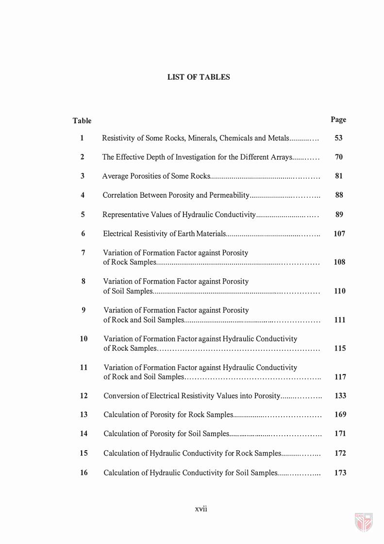
LIST OF TABLES
Table Page
1 Resistivity of Some Rocks, Minerals, Chemicals and Metals . . . . . . . . . . . . . , 53
2 The Effective Depth of Investigation for the Different Arrays. . . . . . . . . . . . 70
3 Average Porosities of Some Rocks. . . . . . . . . . . . . . . . . . . . . . . . . . . . . . . . . . . . . . . . . . . . . . . . . . . . . 81
4 Correlation Between Porosity and Permeability... . . . . . . . . . . . . . . . .. . . . ... . . . . . . . 88
5 Representative Values of Hydraulic Conductivity. . . . . . . . . . . . . . . . . . . . . . . . . .... . 89
6 Electrical Resistivity of Earth Materials . . . . . . . . . . . . . . . ... . . . . . . . . . . . . . . . . . . . . . . . . . . . , 107
7 Variation of Formation Factor against Porosity of Rock Samples. . . . . . . . . . . . . . . . . . . . . . . . . . . . . . . . . . . . . . . . . . . . . . . . . . . . . . . . . . . . . . . . . . . . . . . . . . . . . . . 108
8 Variation of Formation Factor against Porosity of Soil Samples. . . . . . . . . . . . . . . . . . . . . . . . . . ......... ................................ . . . . . . . . . . . . . . 110
9 Variation of Formation Factor against Porosity of Rock and Soil Samples . . . . . . . . . . . . . . . . . . . . . . . ,. .......... ............ . . . . . . . . . . . . . . . . . 111
10 Variation of Formation Factor against Hydraulic Conductivity of Rock Samples. . . . . . . . . . . . . . . ... ............ ...... ........................... 115
11 Variation of Formation Factor against Hydraulic Conductivity of Rock and Soil Samples . . . . . . . . . . . . . . . . . . . . . . . . . . . . . . . . . . . . ... . . . . . . . . . . . . . . 117
12 Conversion of Electrical Resistivity Values into Porosity. . . . . . . . . . . . . . . . .. 133
13 Calculation of Porosity for Rock Samples... . . . . . . . . . . . . . . . . . . . . . . . . . . . . ....... 169
14 Calculation of Porosity for Soil Samples. .... .... ....... ...... . . . . . . . . . . . . . . . . . .. 171
15 Calculation of Hydraulic Conductivity for Rock Samples. . . . . . . . . . . . . . . ... 172
16 Calculation of Hydraulic Conductivity for Soil Samples. . . . . . . . . . . . . . . .... 173
XVll
17
18
Elevation of the Bedrock . . . . . . . . . . . . . . . . . . . . . . .. . . . . . . . . . . . . . . . . . . . . . . . . . . . . . .
Depth to the Bedrock . . . . . . . . . . . . . . . . . . . . . . . . . . . . . . . . . . . . . . . . . . . . . . . . . . . . . . . . . .
xviii
189
190
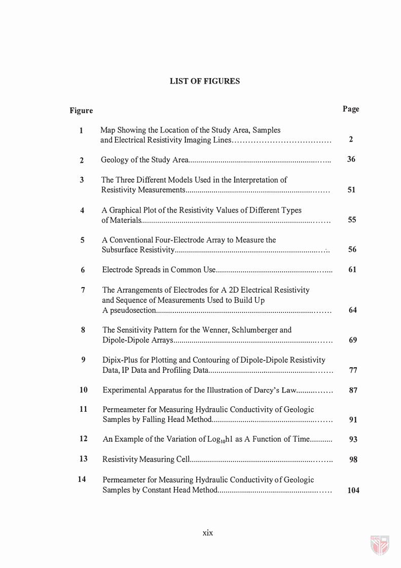
LIST OF FIGURES
Figure Page
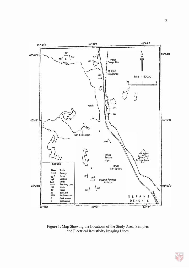
1 Map Showing the Location of the Study Area, Samples and Electrical Resistivity Imaging Lines . . . . . . . . . . . . . . . . . . . . . . . . . . . . . . . . . . . . . 2
2 Geology of the Study Area . . . . . . . . . . . . . . . . . . . . . . . ... . . . . . . . . . . . . . . . . . . . . . . . . . . . . . . . . . . . . . . . . . . . 36
3 The Three Different Models Used in the Interpretation of
4
5
6
7
8
9
10
11
12
13
14
Resistivity Measurements . . . . . . . . . . . . . . . . ........... ..... ....... . ....... ....... ........ . . . . . . . 51
A Graphical Plot of the Resistivity Values of Different Types of Materials ................................... ................................................. . . . . . . .
A Conventional Four-Electrode Array to Measure the Subsurface Resistivity . . . . . . . . . . . . . . . . . . . . . . . . . . . . . . . . . . . . . . . . . . . . . . . . . . . . . . . . . . . . . . . . . . . . . . . . . . . .
Electrode Spreads in Common Use . . . . . . . . . . . . . . . . . . . . . . . . . . . . . . . . . . . . . . . . . . . . . . . . . . . . . . . .
The Arrangements of Electrodes for A 2D Electrical Resistivity and Sequence of Measurements Used to Build Up A pseudosection . . . . . . . ... . . . . . . . . . . . . . . . . . . . . . . . . . . . . . . . . . . . . . . . . . . . . . . . . . . . . . . . . . . . . . . . . . . . . . . . . . .
The Sensitivity Pattern for the Wenner, Schlumberger and Dipole-Dipole Arrays . . . . . . . . . . . . . . . . . . . . . . . . . . . . . . . . . . . . . . . . . . . . . . . . . . . . . . . . . . . . . . . . . . . . . . . . . . . .
Dipix-Plus for Plotting and Contouring of Dipole-Dipole Resistivity Data, IP Data and Profiling Data . . . . . . . . . . . . . . . . . . . . . . . . . . ... . . . . . . . . . . . . . . . . . . . . . . . . . . . . . .
Experimental Apparatus for the Illustration of Darcy's Law .......... . . . .. .
Permeameter for Measuring Hydraulic Conductivity of Geologic Samples by Falling Head Method . . . . . . . . . . . . . . . . . . ... . . . . . . . . . . . . . . . . . . . . . . . . . . . . . . . . . . . .
An Example of the Variation ofLogJOhl as A Function of Time . . . . . . . . . ..
Resistivity Measuring CelL . . . . . . . . . . . . . . . . . . . . . . . . . . . . . . . . . . . . . . . . . . . . . . . . . . . . . . . . . . . . . . . . . .
Permeameter for Measuring Hydraulic Conductivity of Geologic Samples by Constant Head Method . . . . . . . . . . . . . . ... . . . . . . . . . ... . . . ... . . . . . . . . . . . . . . . . . . .
XIX
55
56
6 1
64
69
77
87
9 1
93
98
104
15 Variation of Formation Factor against Porosity of Rock Samples. . . . . . . . . . . . . . . . . . . . . . . . . . . . . . . . . . . . . . . . . . . . . . . . . . . . . . . ... . . . . . . . . . . . . . . . . . . . . . . . . . . . . . . . . . . . . . . . 109
16 Variation of Formation Factor against Porosity of Soil Samples.. . . . . . . . . . . . . . . ............ ...................... ......................................... . . . . .. 110
17 Variation of Formation Factor against Porosity of Rock and Soil Samples. . . . . . . . . . . . . . . . . . . . . . . . . . . . .................... ..... ........................... . . .. 113
18 Variation of Formation Factor against Hydraulic Conductivity of Rock Samples. . . . . . . . . . . . . . . . . . . . . . . . . . . . . . . . . . . . . . . . . . . . . . . . . . . . . . . . . . . . . . . . . . . . . . . . . . . . . . . . . . . . 116
19 Variation of Formation Factor against Hydraulic Conductivity of Soil Samples. . . . . . . . . . . . . ... . . . . . . . . . . . ... . . . . . . . . . . . . . . . . . . . . . . . . . . . . . . . . . . . . . . . . . . . . . . . . . . . . . . . 117
20 Distribution of Electrical Resistivity Values along Bukit Jalil Line 1 . . . . 119
21 Distribution of Electrical Resistivity Values along Bukit Jalil Line 2. . . . 120
22 Distribution of Electrical Resistivity Values along Bukit Jalil Line 3 . . . . 121
23 Distribution of Electrical Resistivity Values along Bukit Jalil Line 4.. . 122
24 Distribution of Electrical Resistivity Values along Bukit Jalil Line 7 . . . . 123
25 Distribution of Electrical Resistivity Values along Bukit Jalil Line 5.... 124
26 Distribution of Electrical Resistivity Values along Bukit Jalil Line 6.... 125
27 Distribution of Electrical Resistivity Values along Bukit Jalil Line 8.... 126
28 Distribution of Electrical Resistivity Values along Apm Line. . . . . . . . . . . . ... 127
29 Distribution f Electrical Resistivity Values along Taman University Line... . . . . . . . . . . . . . . . . . . . . . . . . . . . . . . . . . . . . . . . . . . . . . . . . . . . . . . . . . . . . . . . . . . . . . . . . . . . . . . . . . . . . .. . . . . . . . . . . . . 128
30 Distribution of Electrical Resistivity Values along Mardi Line 1 . . . . . . . . . . 129
31 Distribution of Electrical Resistivity Values along Mardi Line 2 . . . . . . . . . . 130
32 Distribution of Electrical Resistivity Values along Mardi Line 3 . . . . . . . . . . 131
33 Subsurface Porosity Distribution along Line Bukit Jalil 1................... . . 135
xx
34 Subsurface Porosity Distribution along Line Bukit Jalil 2..................... 136
35 Subsurface Porosity Distribution along Line Bukit Jalil3. . . . . . . . . . . . . . . . . . . . . 137
36 Subsurface Porosity Distribution along Line Bukit Ja1il 4 . . . . . . . . . . . . . . . . . . . . . 138
37 Subsurface Porosity Distribution along Line Bukit Jalil 7...................... 139
38 Subsurface Porosity Distribution along Line Bukit Jalil 5 . . . . . . . . . . . . . . . . . . . . . . 140
39 Subsurface Porosity Distribution along Line Bukit JaliI 6 . . . . . . . . . . . . . . . . . . . . . . 141
40 Subsurface Porosity Distribution along Line Bukit Jalil 8...................... 142
41 Subsurface Porosity Distribution along Apm Line. . . . . . . . . . . . . . . . . . . . . . . . . . . . . . . . . 143
42 Subsurface Porosity Distribution along Taman University Line. . . . . . . . . . . . 144
43 Subsurface Porosity Distribution along Mardi Line 1 . . . . . . . . . . . . . . . . . . . .......... 145
44 Subsurface Porosity Distribution along Mardi Line 2. ................. ..... ..... 146
45 Subsurface Porosity Distribution along Mardi Line 3 . . . . . . . . . . . . . . . . . . . . . . . . . . . . 147
46 Bedrock Contour. . . . . . . . . . . . . .. . . . . . . . . . . . . . . . . . . . . . . . . . . . . . . . . . . . . . . . . . . . . . . . . . . . . . . . . . . . . . . . . . . . . 150
47 3-D View of the Top of the Bedrock. . . . . . . . . . . . . . . . . . . . . . . . . . . . . . . . . . . . . . . . . . . . . . . . . . . . . . 151
48 3-D view of the Depth to the Bedrock . . . . . . . . . . . . . . . . . . . . . . . . . . . ......... ... 151
49 Geological Profile for Borehole 1 . . .. . . . . . . . . . . . . . . . . . . . . . . . . . . . . . . . . . . . . . . . . . . . . . . . . . . 166
50 Geological Profile for Borehole 2 . . . . . . . . . . . . . . . . . . . . . . . . . . . . . . . . . . . . . . . . . . . . . . . . . . . . . . . . 167
51 Geological Profile for Borehole 3 . . . . . . . . . ............ ............ ............ 168
52 Variation of Formation factor against Porosity of Rock and Soil Samples using Curve Fit . . . . . . . . . . . . . . . . . . . . . . . . .......... ................ 188
XXI
CHAPTER I
INTRODUCTION
Groundwater is a major source of clean drinking water all over the world. It
has been an important resource especially in the dry part of the world. Groundwater
has been used in Malaysia for many decades (Ang, 1 994).
Increased demands for water have stimulated development of underground
water resources. As a result, techniques for investigating the occurrence and
movement of groundwater have been improved, better equipment for extracting has
been developed, concepts for resource management have been established, and the
research has contributed to a better understanding of the subject.
Since geophysical exploration is the scientific measurement of physical
properties of the earth crust for investigation of mineral deposits or geologic
structure, the present project conducted mainly to apply electrical resistivity
method in groundwater exploration, in particular to estimate the groundwater
reserve within the unconfined aquifer.
03"02'u
� �oJ LEGENDS - Roads
- Railways
c; R.�m ru\ Contours
cO Lakes 03 "OO'U r-- Resistivity Lmes
Md Mard. Md2\ TU Taman BJ Buk.tJahl APM Aor-Cooo.hOllet R Rotk samples S Soli Samples
S
Mdl -
BJ8
s
Pekon SUngol Besl
Kg Syed Mohommad
APM\
Tomon Serdonq .Joyo
Toman Sen Seroong
UolVerult PertOllion M,,!u)sIO
\Md3
101"44'T
N
t Scale I 50000
o
do
��� �I� Pekon Serdo£2j,omo
DENGKIL 101040T 101042'T 101°44 T
Figure 1: Map Showing the Locations of the Study Area, Samples and Electrical Resistivity Imaging Lines
2 I
2
03°0tU
03"00'U
3
PREVIOUS WORK IN THE STUDY AREA
The geological survey of Malaysia first started hydrogeological
investigations in Peninsular Malaysia in 1 903. The only previous published
account of the geology of the whole of the present area was entitled "Account of
the geology and mining industries of south Selangor and Negeri Sembilan"
(Will bourn 1 922). A geological map accompanies this publication on a scale of
1 inch to 4 miles.
Ahmed and Othman ( 1 992, 1 997), usmg DC resistivity and other
methods to provide sharp lateral resistivity variations by electrical profiling
carried out two geophysical investigations. The resistivity profiling was carried
out at Sungai Besi Toll plaza along the Kuala Lumpur-Seremban Highway
using Wenner array with 1 0m-electrode spacing. They found that in the first
line, the southern part has low resistivity value due to higher water and higher
clay content. In the second line the resistivity profiling results show localized
anomalies occurring at several parts of the line which is most probably due to
the presence of week zones in the sediment layer.
OBJECTIVES OF THE PRESENT STUDY
The pnmary objective of the present study is to apply electrical
resistivity method in the quantitative assessment of groundwater reserve. From
the combination of the resistivity techniques used in the field, processing and