università degli studi di pisa facoltà di ingegneria ... · università degli studi di pisa...
TRANSCRIPT
1
Paolo Clemente Limit analysis of masonry arch bridges 1
LIMIT ANALYSIS OF MASONRY ARCH BRIDGES
Paolo Clemente
Università degli Studi di PisaFacoltà di Ingegneria
Dottorato in Scienze e Tecniche dell’Ingegneria Civile26 maggio 2006
Paolo Clemente Limit analysis of masonry arch bridges 2
LIMIT ANALYSIS OF MASONRY ARCH BRIDGES
Limit analysis
Funicular arch
Check under dead loads
Check under moving loads
Check under horizontal actions
2
Paolo Clemente Limit analysis of masonry arch bridges 3
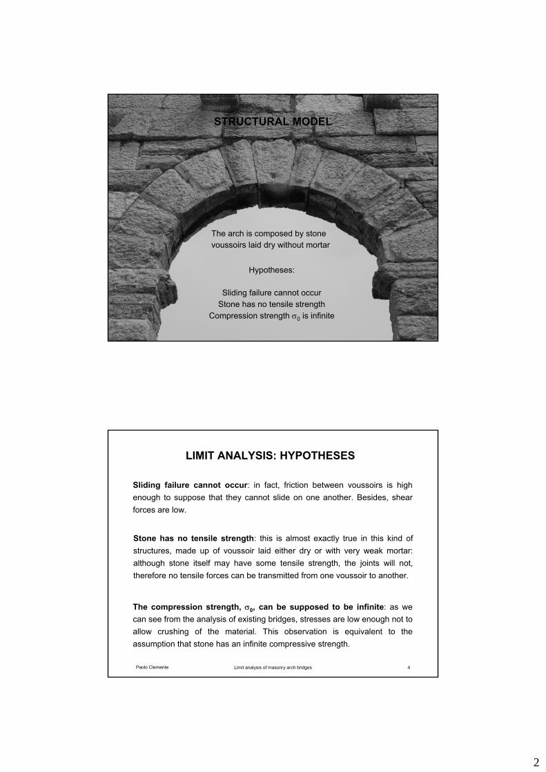
STRUCTURAL MODEL
The arch is composed by stone voussoirs laid dry without mortar
Hypotheses:
Sliding failure cannot occurStone has no tensile strength
Compression strength σ0 is infinite
Paolo Clemente Limit analysis of masonry arch bridges 4
LIMIT ANALYSIS: HYPOTHESES
Stone has no tensile strength: this is almost exactly true in this kind of structures, made up of voussoir laid either dry or with very weak mortar: although stone itself may have some tensile strength, the joints will not, therefore no tensile forces can be transmitted from one voussoir to another.
Sliding failure cannot occur: in fact, friction between voussoirs is high enough to suppose that they cannot slide on one another. Besides, shear forces are low.
The compression strength, σ0, can be supposed to be infinite: as we can see from the analysis of existing bridges, stresses are low enough not to allow crushing of the material. This observation is equivalent to the assumption that stone has an infinite compressive strength.
3
Paolo Clemente Limit analysis of masonry arch bridges 5
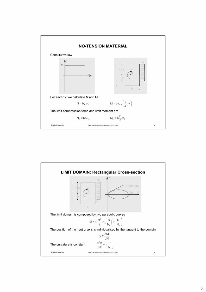
NO-TENSION MATERIAL
0 t M = byσ -y2
⎛ ⎞⎜ ⎟⎝ ⎠
0 N = by σ
For each “y” we calculate N and M:
ε
σ
σ 0
Constitutive law
tb = N 00 σ
The limit compression force and limit moment are2
0 0 t M = b σ8
Paolo Clemente Limit analysis of masonry arch bridges 6
LIMIT DOMAIN: Rectangular Cross-section
⎟⎟⎠
⎞⎜⎜⎝
⎛σ±
00 0
2
NN- 1
NN
2bt = M
dNdM= y
b
1 = dN
Md 0
2
2
σm
The position of the neutral axis is individualised by the tangent to the domain
The limit domain is composed by two parabolic curves
The curvature is constant
4
Paolo Clemente Limit analysis of masonry arch bridges 7
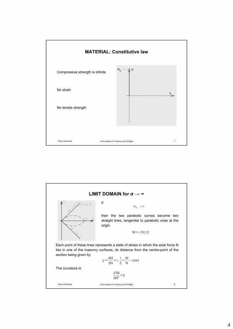
MATERIAL: Constitutive law
Compressive strength is infinite
No strain
No tensile strength
ε
σσ 0
Paolo Clemente Limit analysis of masonry arch bridges 8
LIMIT DOMAIN for σ → ∞
2t N = M ±
tcosNM=
2t =
dNdM= y =±
0 = dN
Md 2
2
∞σ → 0 If
Each point of these lines represents a state of stress in which the axial force N lies in one of the masonry surfaces, its distance from the centre-point of the section being given by
then the two parabolic curves become two straight lines, tangential to parabolic ones at the origin
The curvature is
5
Paolo Clemente Limit analysis of masonry arch bridges 9
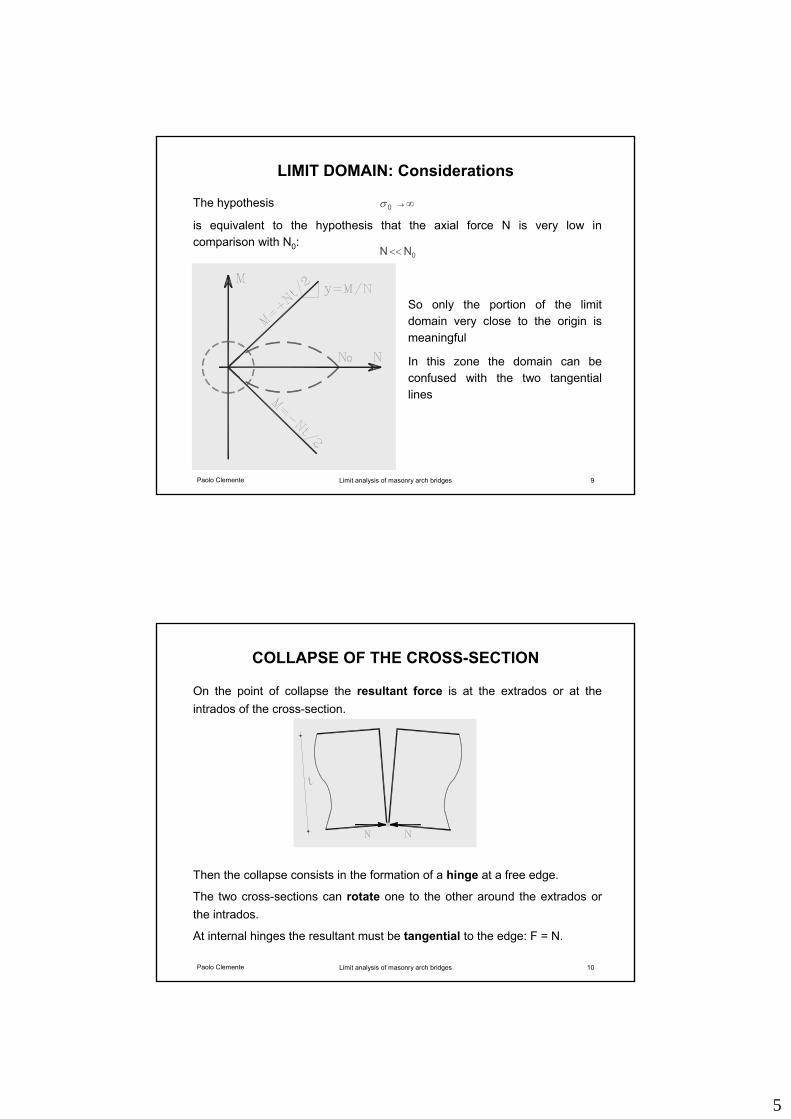
LIMIT DOMAIN: Considerations
The hypothesis
So only the portion of the limit domain very close to the origin is meaningful
In this zone the domain can be confused with the two tangential lines
is equivalent to the hypothesis that the axial force N is very low in comparison with N0:
∞→ 0 σ
0N N <<
Paolo Clemente Limit analysis of masonry arch bridges 10
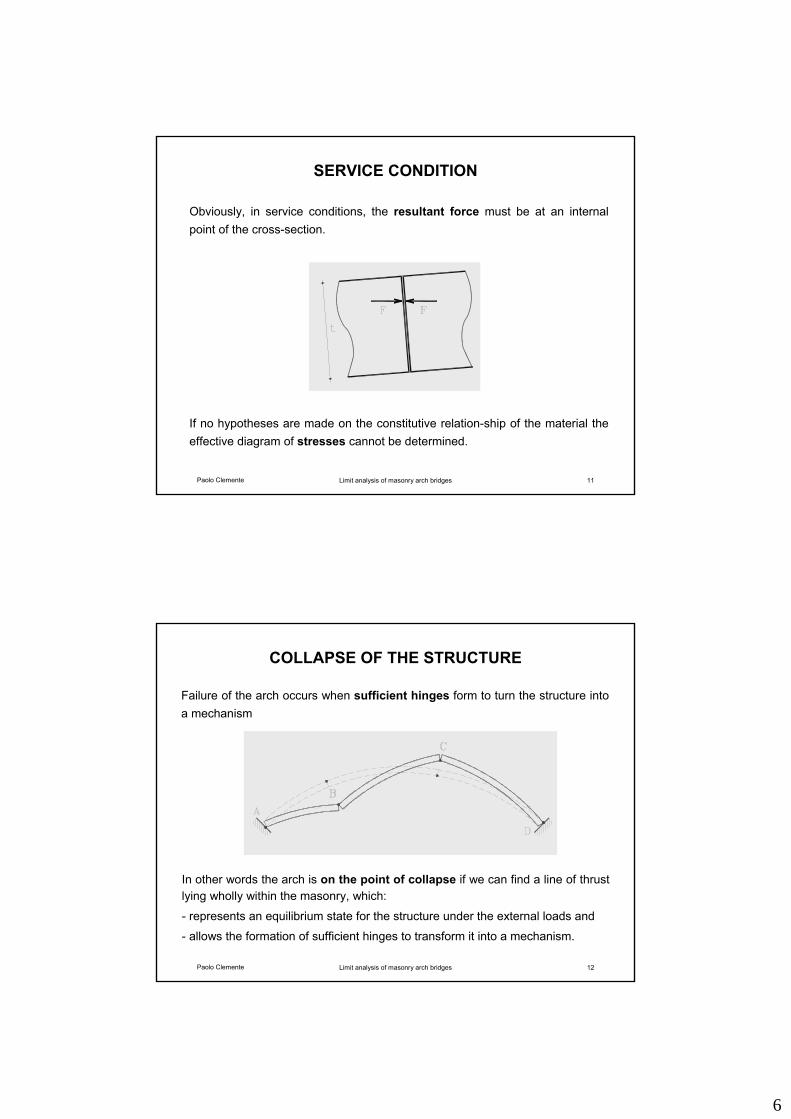
COLLAPSE OF THE CROSS-SECTION
On the point of collapse the resultant force is at the extrados or at the intrados of the cross-section.
Then the collapse consists in the formation of a hinge at a free edge.
The two cross-sections can rotate one to the other around the extrados or the intrados.
At internal hinges the resultant must be tangential to the edge: F = N.
6
Paolo Clemente Limit analysis of masonry arch bridges 11
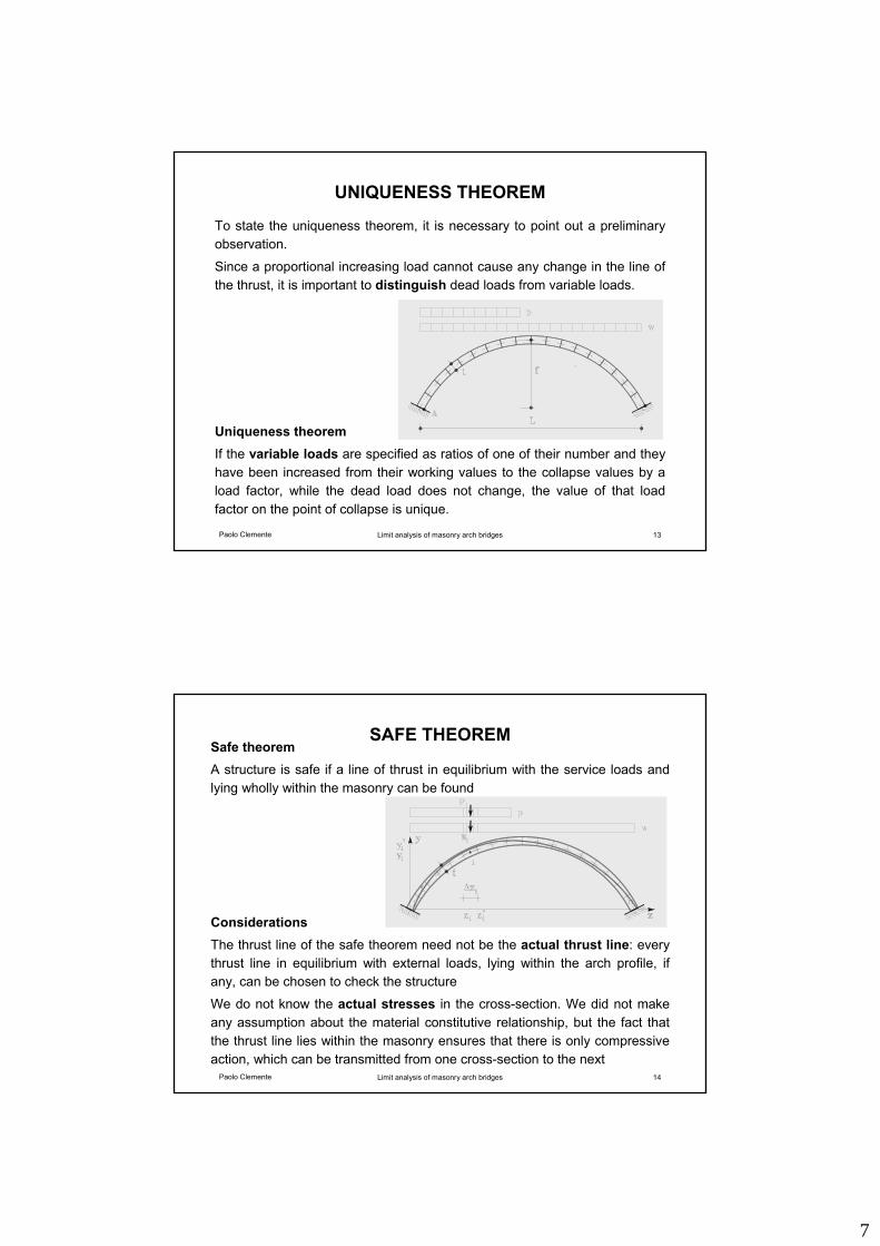
SERVICE CONDITION
If no hypotheses are made on the constitutive relation-ship of the material the effective diagram of stresses cannot be determined.
Obviously, in service conditions, the resultant force must be at an internal point of the cross-section.
Paolo Clemente Limit analysis of masonry arch bridges 12
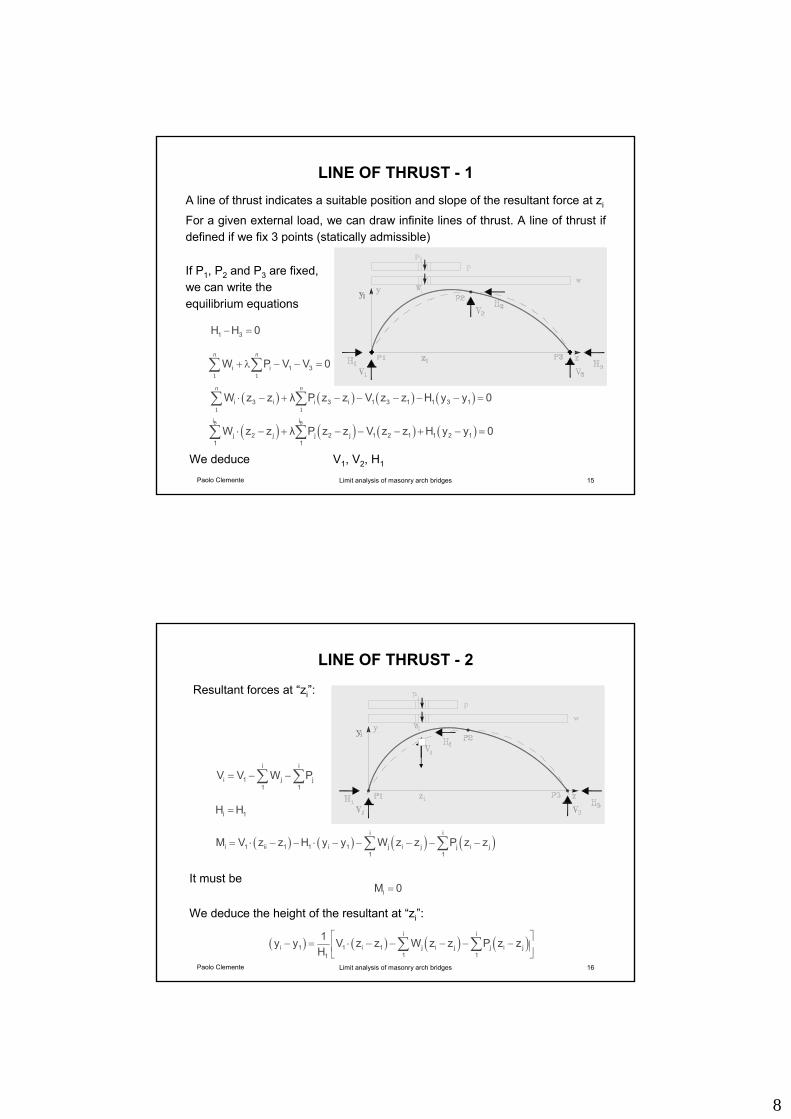
COLLAPSE OF THE STRUCTURE
In other words the arch is on the point of collapse if we can find a line of thrust lying wholly within the masonry, which:
- represents an equilibrium state for the structure under the external loads and
- allows the formation of sufficient hinges to transform it into a mechanism.
Failure of the arch occurs when sufficient hinges form to turn the structure into a mechanism
7
Paolo Clemente Limit analysis of masonry arch bridges 13
UNIQUENESS THEOREM
To state the uniqueness theorem, it is necessary to point out a preliminary observation.
Since a proportional increasing load cannot cause any change in the line of the thrust, it is important to distinguish dead loads from variable loads.
Uniqueness theoremIf the variable loads are specified as ratios of one of their number and they have been increased from their working values to the collapse values by a load factor, while the dead load does not change, the value of that load factor on the point of collapse is unique.
Paolo Clemente Limit analysis of masonry arch bridges 14
SAFE THEOREMSafe theoremA structure is safe if a line of thrust in equilibrium with the service loads and lying wholly within the masonry can be found
ConsiderationsThe thrust line of the safe theorem need not be the actual thrust line: every thrust line in equilibrium with external loads, lying within the arch profile, if any, can be chosen to check the structure
We do not know the actual stresses in the cross-section. We did not make any assumption about the material constitutive relationship, but the fact that the thrust line lies within the masonry ensures that there is only compressive action, which can be transmitted from one cross-section to the next
8
Paolo Clemente Limit analysis of masonry arch bridges 15
LINE OF THRUST - 1A line of thrust indicates a suitable position and slope of the resultant force at zi
For a given external load, we can draw infinite lines of thrust. A line of thrust if defined if we fix 3 points (statically admissible)
1 1i i 1 3W P V V 0
n n
+ λ − − =∑ ∑
( ) ( ) ( ) ( )1 1
i 3 i i 3 i 1 3 1 1 3 1W z z λ P z z V z z H y y 0n n
⋅ − + − − − − − =∑ ∑
( ) ( ) ( ) ( )B Bi i
j 2 j j 2 j 1 2 1 1 2 11 1
W z z λ P z z V z z H y y 0⋅ − + − − − + − =∑ ∑
1 3H H 0− =
We deduce V1, V2, H1
If P1, P2 and P3 are fixed, we can write the equilibrium equations
Paolo Clemente Limit analysis of masonry arch bridges 16
LINE OF THRUST - 2
i i
i 1 j j1 1
V V W P= − −∑ ∑
i 1H H=
( ) ( ) ( ) ( )i i
i 1 ii 1 1 i 1 j i j j i j1 1
M V z z H y y W z z P z z= ⋅ − − ⋅ − − − − −∑ ∑
Resultant forces at “zi”:
( ) ( ) ( ) ( )i i
i 1 1 i 1 j i j j i j1 11
1y y V z z W z z P z zH
⎡ ⎤− = ⋅ − − − − −⎢ ⎥
⎣ ⎦∑ ∑
We deduce the height of the resultant at “zi”:
iM 0=It must be
9
Paolo Clemente Limit analysis of masonry arch bridges 17
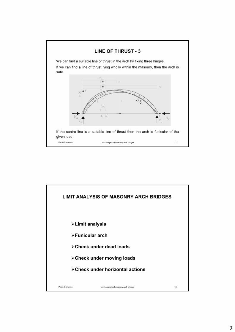
LINE OF THRUST - 3
We can find a suitable line of thrust in the arch by fixing three hinges.
If we can find a line of thrust lying wholly within the masonry, then the arch is safe.
∆ s
If the centre line is a suitable line of thrust then the arch is funicular of the given load
Paolo Clemente Limit analysis of masonry arch bridges 18
LIMIT ANALYSIS OF MASONRY ARCH BRIDGES
Limit analysis
Funicular arch
Check under dead loads
Check under moving loads
Check under horizontal actions
10
Paolo Clemente Limit analysis of masonry arch bridges 19
FUNICULAR ARCH
The arch is funicular with reference to a load condition
The arch is funicular with reference to a load condition if so is its centre line
Usually, we consider arches funicular with reference to dead loads
Suppose dead load to be uniformly distributed along the span, then the centre line of the funicular arch has parabolic shape
We consider moving load coming on to the bridge.
So the load condition consists in a uniformly distributed load between z=0 and the end load abscissa zp, which individualised the load condition
Paolo Clemente Limit analysis of masonry arch bridges 20
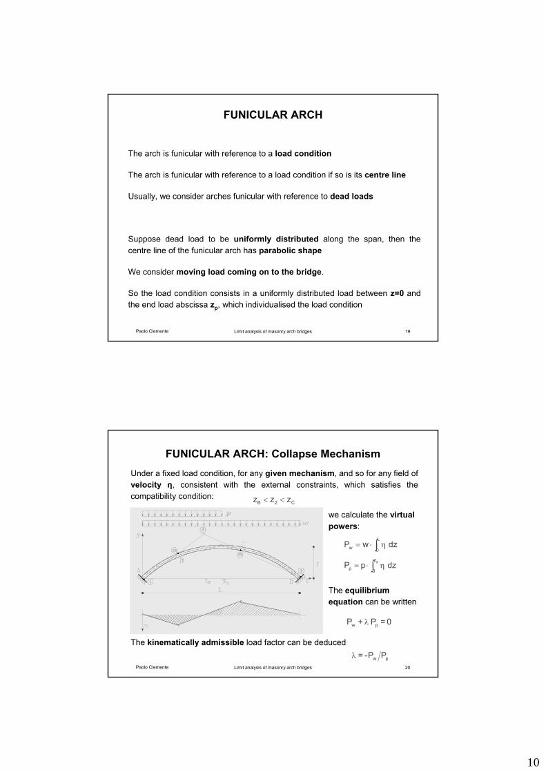
FUNICULAR ARCH: Collapse Mechanism
∫ η⋅=L
0w dzwP
∫ η⋅= pz
0p dzpP
C2B zzz <<
Under a fixed load condition, for any given mechanism, and so for any field of velocity η, consistent with the external constraints, which satisfies the compatibility condition:
we calculate the virtual powers:
0 = P + P pw λ
PP-= pwλ
The equilibrium equation can be written
The kinematically admissible load factor can be deduced
11
Paolo Clemente Limit analysis of masonry arch bridges 21
FUNICULAR ARCH: Equilibrium Equation
0 = P + P pw λ
) ) load factor = min (kinematic admissible = max (statically admissible λ λ
there are no terms with the internal forces acting at the hinges.
This circumstance is greatly appreciable, because the values of the internal forces are still unknown
We must find the minimum kinematically admissible load factor, which is also statically admissible:
It is very important to observe that in the equilibrium equation
This can be done by using an iteration procedure.
Paolo Clemente Limit analysis of masonry arch bridges 22
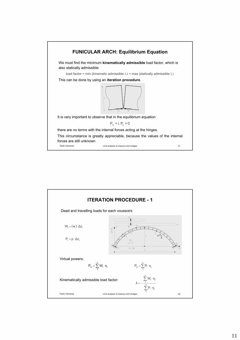
ITERATION PROCEDURE - 1
∑ ⋅=n
1iiw ηWP ∑ ⋅=
n
1iip ηPP
( ) ii ∆zwW ⋅=
ii ∆zpP ⋅=
∑
∑
⋅
⋅−= n
1ii
n
1ii
ηP
ηWλ
Dead and travelling loads for each voussoirs
Virtual powers:
Kinematically admissible load factor:
∆ s
12
Paolo Clemente Limit analysis of masonry arch bridges 23
ITERATION PROCEDURE - 2
0VVPW DAii =−−λ+ ∑∑nn
11
( ) ( ) ( ) ( ) 0yyHzzVzzPλzzW ADAADAiDiiDi =−−−−−+−⋅ ∑∑nn
11
( ) ( ) ( ) ( ) 0yyHzzVzzPλzzW ABAABA
i
1jBj
i
1jBj
BB
=−+−−−+−⋅ ∑∑
0HH DA =−
Equilibrium equations
We deduce VA, VD, HA
λλ
Loads: w + λp
Paolo Clemente Limit analysis of masonry arch bridges 24
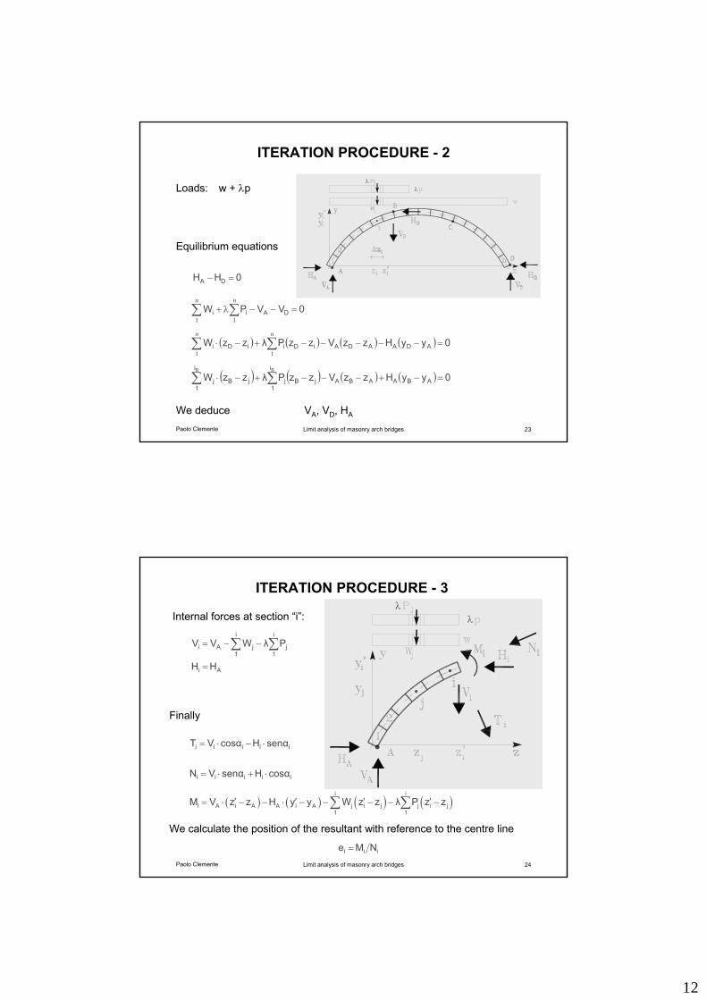
ITERATION PROCEDURE - 3
∑∑ −−=i
1j
i
1jAi PλWVV
Ai HH =
iiiii cosαHsenαVN ⋅+⋅=
iiiii senαHcosαVT ⋅−⋅=
( ) ( ) ( ) ( )i i
i A i A A i A j i j j i j1 1
M V z z H y y W z z λ P z z′ ′ ′ ′= ⋅ − − ⋅ − − − − −∑ ∑
iii NMe =
Internal forces at section “i”:
Finally
λλ
We calculate the position of the resultant with reference to the centre line
13
Paolo Clemente Limit analysis of masonry arch bridges 25
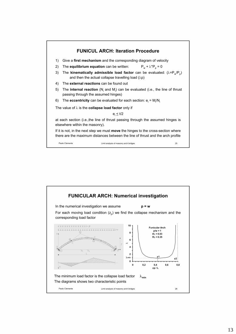
FUNICUL ARCH: Iteration Procedure
1) Give a first mechanism and the corresponding diagram of velocity
2) The equilibrium equation can be written: Pw + λ*Pp = 0
3) The kinematically admissible load factor can be evaluated: (λ=Pw/Pp)and then the actual collapse travelling load (λp)
4) The external reactions can be found out
5) The internal reaction (Ni and Mi) can be evaluated (i.e., the line of thrustpassing through the assumed hinges)
6) The eccentricity can be evaluated for each section: ei = Mi/Ni
The value of λ is the collapse load factor only if ei < t/2
at each section (i.e.,the line of thrust passing through the assumed hinges is elsewhere within the masonry).
If it is not, in the next step we must move the hinges to the cross-section where there are the maximum distances between the line of thrust and the arch profile
Paolo Clemente Limit analysis of masonry arch bridges 26
FUNICULAR ARCH: Numerical investigation
The minimum load factor is the collapse load factor λmin
In the numerical investigation we assume p = w
For each moving load condition (zp) we find the collapse mechanism and the corresponding load factor
The diagrams shows two characteristic points
Funicular Archp/w = 1
t/L = 0.03f/L = 0.35
0
2
4
6
8
10
0 0,2 0,4 0,6 0,8zp / L
λ
λmin z1z2
14
Paolo Clemente Limit analysis of masonry arch bridges 27
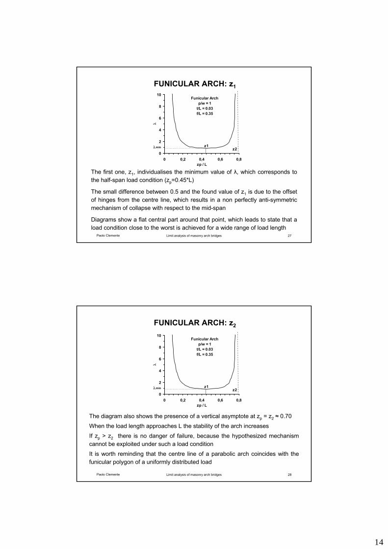
FUNICULAR ARCH: z1
The first one, z1, individualises the minimum value of λ, which corresponds to the half-span load condition (zp=0.45*L)
The small difference between 0.5 and the found value of z1 is due to the offset of hinges from the centre line, which results in a non perfectly anti-symmetric mechanism of collapse with respect to the mid-span
Diagrams show a flat central part around that point, which leads to state that a load condition close to the worst is achieved for a wide range of load length
Funicular Archp/w = 1
t/L = 0.03f/L = 0.35
0
2
4
6
8
10
0 0,2 0,4 0,6 0,8zp / L
λ
λmin z1z2
Paolo Clemente Limit analysis of masonry arch bridges 28
FUNICULAR ARCH: z2
The diagram also shows the presence of a vertical asymptote at zp = z2 ≈ 0.70
When the load length approaches L the stability of the arch increases
If zp > z2 there is no danger of failure, because the hypothesized mechanism cannot be exploited under such a load condition
It is worth reminding that the centre line of a parabolic arch coincides with the funicular polygon of a uniformly distributed load
Funicular Archp/w = 1
t/L = 0.03f/L = 0.35
0
2
4
6
8
10
0 0,2 0,4 0,6 0,8zp / L
λ
λmin z1z2
15
Paolo Clemente Limit analysis of masonry arch bridges 29
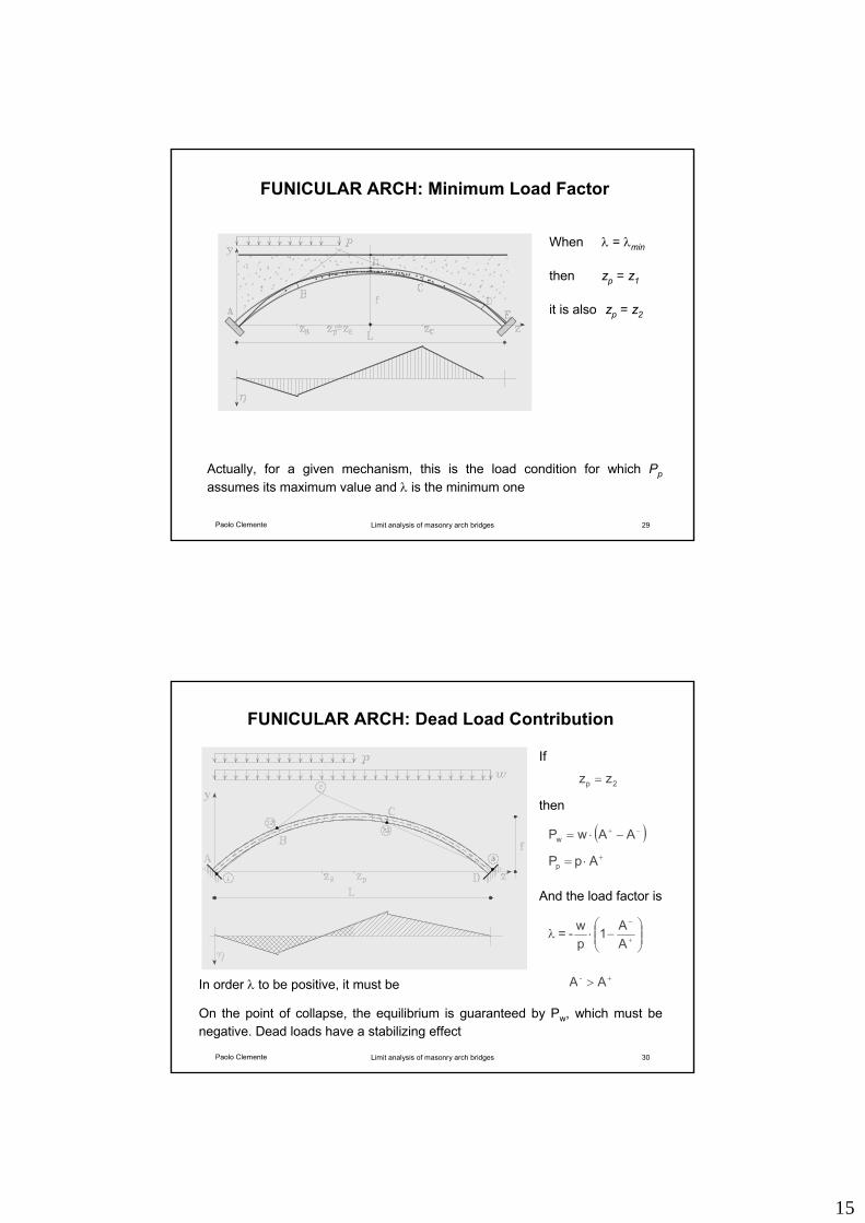
FUNICULAR ARCH: Minimum Load Factor
When λ = λmin
then zp = z1
it is also zp = z2
Actually, for a given mechanism, this is the load condition for which Ppassumes its maximum value and λ is the minimum one
Paolo Clemente Limit analysis of masonry arch bridges 30
FUNICULAR ARCH: Dead Load Contribution
2p zz =
( )−+ −⋅= AAwPw
+⋅= ApPp
AA1
pw-= ⎟⎟
⎠
⎞⎜⎜⎝
⎛−⋅λ +
−
+> A A-
If
In order λ to be positive, it must be
On the point of collapse, the equilibrium is guaranteed by Pw, which must be negative. Dead loads have a stabilizing effect
And the load factor is
then
16
Paolo Clemente Limit analysis of masonry arch bridges 31
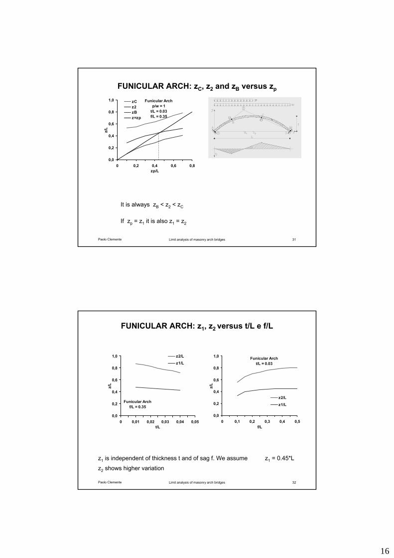
FUNICULAR ARCH: zC, z2 and zB versus zp
It is always zB < z2 < zC
If zp = z1 it is also z1 = z2
Funicular Archp/w = 1
t/L = 0.03f/L = 0.35
0,0
0,2
0,4
0,6
0,8
1,0
0 0,2 0,4 0,6 0,8zp/L
z/L
zCz2zBz=zp
Paolo Clemente Limit analysis of masonry arch bridges 32
FUNICULAR ARCH: z1, z2 versus t/L e f/L
z1 is independent of thickness t and of sag f. We assume z1 = 0.45*L
z2 shows higher variation
Funicular Archf/L = 0.35
0,0
0,2
0,4
0,6
0,8
1,0
0 0,01 0,02 0,03 0,04 0,05t/L
z/L
z2/L
z1/LFunicular Arch
t/L = 0.03
0,0
0,2
0,4
0,6
0,8
1,0
0 0,1 0,2 0,3 0,4 0,5f/L
z/L
z2/L
z1/L
17
Paolo Clemente Limit analysis of masonry arch bridges 33
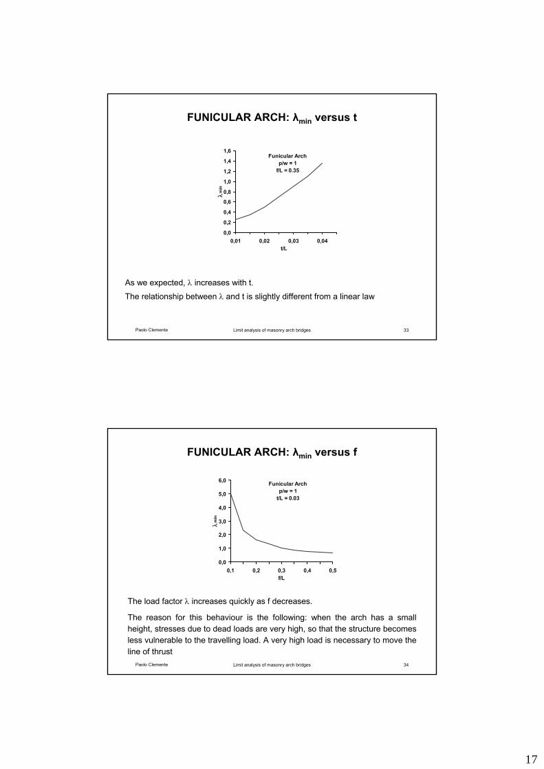
FUNICULAR ARCH: λmin versus t
As we expected, λ increases with t.
The relationship between λ and t is slightly different from a linear law
Funicular Archp/w = 1
f/L = 0.35
0,0
0,2
0,4
0,6
0,8
1,0
1,2
1,4
1,6
0,01 0,02 0,03 0,04t/L
λm
in
Paolo Clemente Limit analysis of masonry arch bridges 34
FUNICULAR ARCH: λmin versus f
The load factor λ increases quickly as f decreases.
The reason for this behaviour is the following: when the arch has a small height, stresses due to dead loads are very high, so that the structure becomes less vulnerable to the travelling load. A very high load is necessary to move the line of thrust
Funicular Archp/w = 1
t/L = 0.03
0,0
1,0
2,0
3,0
4,0
5,0
6,0
0,1 0,2 0,3 0,4 0,5f/L
λm
in
18
Paolo Clemente Limit analysis of masonry arch bridges 36
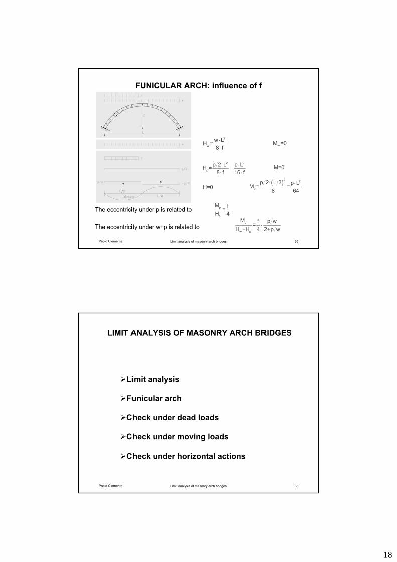
FUNICULAR ARCH: influence of f
2
ww LH =8 f
⋅⋅ wM =0
2 2
pp 2 L p LH =
8 f 16 f⋅ ⋅
=⋅ ⋅
M=0
H=0( )2 2
p
p 2 L 2 p LM = =8 64
⋅ ⋅
p
p
M f=H 4
p
w p
M f p w=H +H 4 2+p w
⋅The eccentricity under w+p is related to
The eccentricity under p is related to
Paolo Clemente Limit analysis of masonry arch bridges 38
LIMIT ANALYSIS OF MASONRY ARCH BRIDGES
Limit analysis
Funicular arch
Check under dead loads
Check under moving loads
Check under horizontal actions
19
Paolo Clemente Limit analysis of masonry arch bridges 39
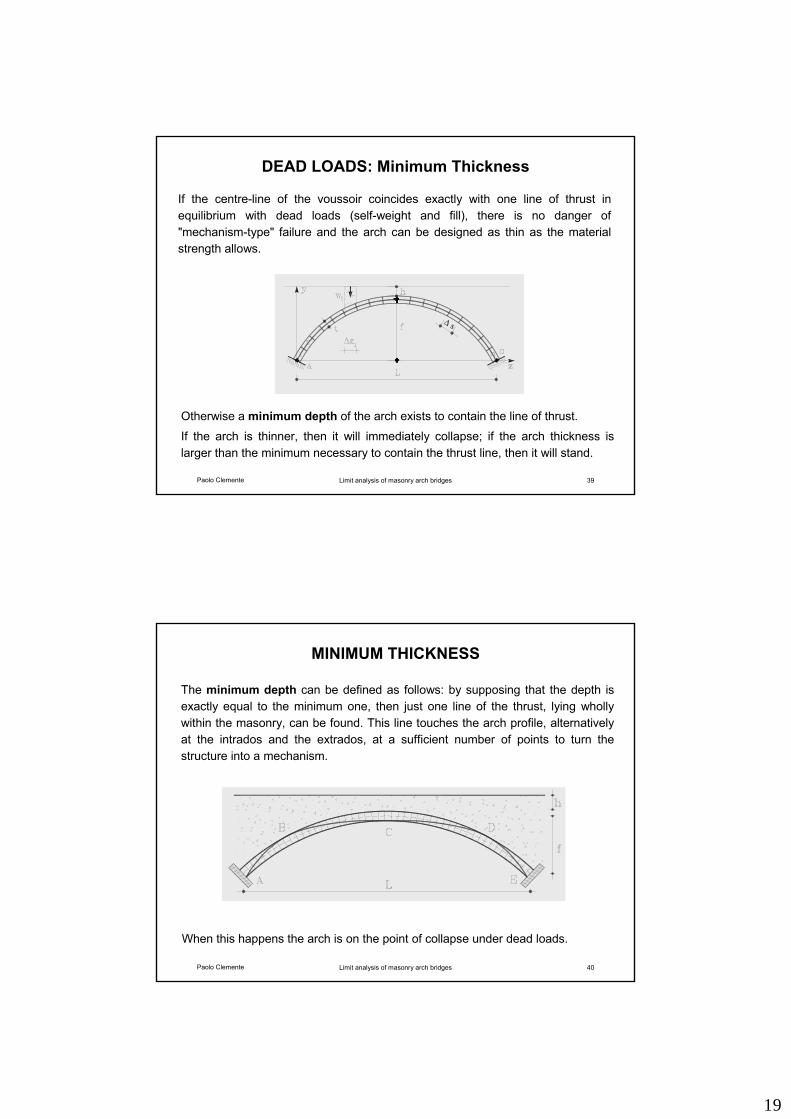
DEAD LOADS: Minimum Thickness
Otherwise a minimum depth of the arch exists to contain the line of thrust.
If the arch is thinner, then it will immediately collapse; if the arch thickness is larger than the minimum necessary to contain the thrust line, then it will stand.
If the centre-line of the voussoir coincides exactly with one line of thrust in equilibrium with dead loads (self-weight and fill), there is no danger of "mechanism-type" failure and the arch can be designed as thin as the material strength allows.
∆ s
Paolo Clemente Limit analysis of masonry arch bridges 40
MINIMUM THICKNESS
The minimum depth can be defined as follows: by supposing that the depth is exactly equal to the minimum one, then just one line of the thrust, lying wholly within the masonry, can be found. This line touches the arch profile, alternatively at the intrados and the extrados, at a sufficient number of points to turn the structure into a mechanism.
When this happens the arch is on the point of collapse under dead loads.
20
Paolo Clemente Limit analysis of masonry arch bridges 41
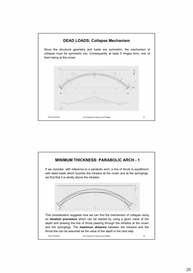
DEAD LOADS: Collapse Mechanism
Since the structural geometry and loads are symmetric, the mechanism of collapse must be symmetric too. Consequently at least 5 hinges form, one of them being at the crown.
Paolo Clemente Limit analysis of masonry arch bridges 42
MINIMUM THICKNESS: PARABOLIC ARCH - 1
This consideration suggests how we can find the mechanism of collapse using an iteration procedure which can be started by using a given value of the depth and drawing the line of thrust passing through the intrados at the crown and the springings. The maximum distance between the intrados and the thrust line can be assumed as the value of the depth in the next step
If we consider, with reference to a parabolic arch, a line of thrust in equilibrium with dead loads which touches the intrados at the crown and at the springings, we find that it is wholly above the intrados
21
Paolo Clemente Limit analysis of masonry arch bridges 43
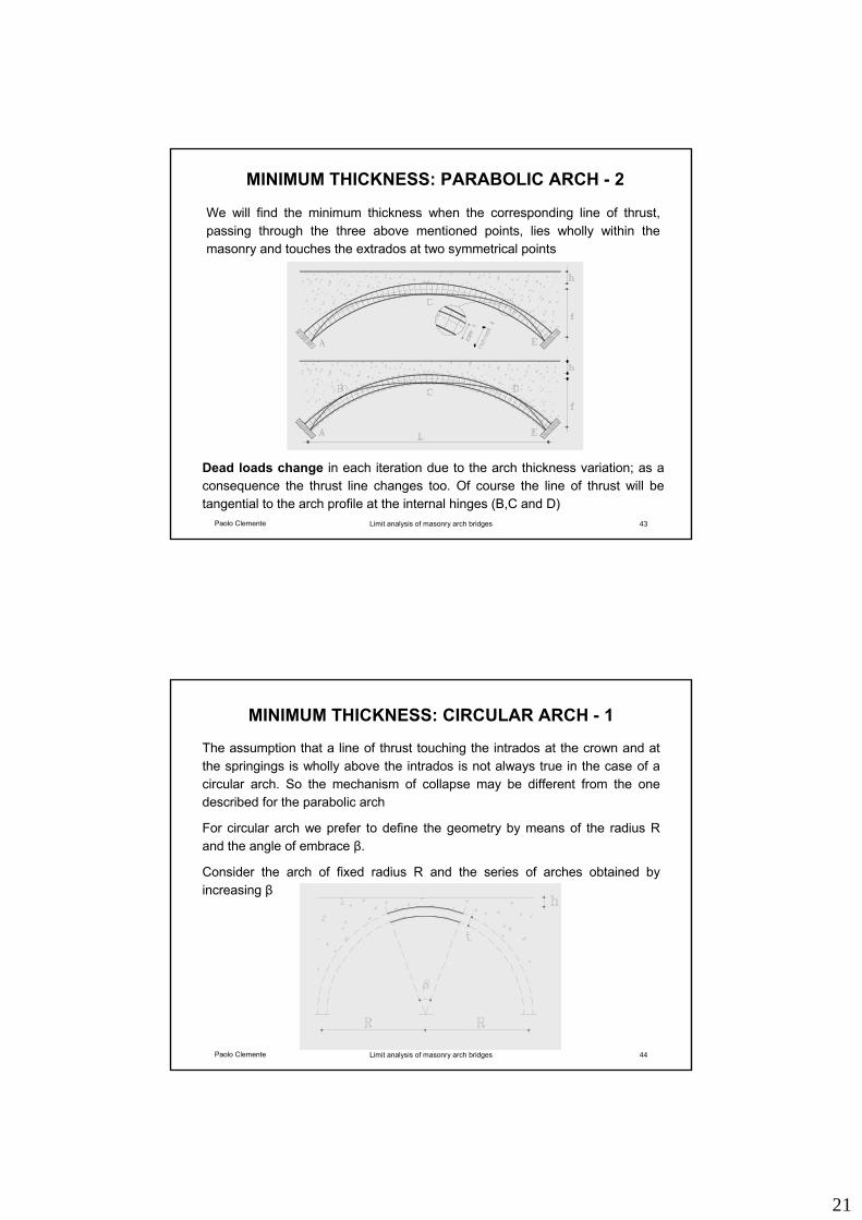
MINIMUM THICKNESS: PARABOLIC ARCH - 2
Dead loads change in each iteration due to the arch thickness variation; as a consequence the thrust line changes too. Of course the line of thrust will be tangential to the arch profile at the internal hinges (B,C and D)
We will find the minimum thickness when the corresponding line of thrust, passing through the three above mentioned points, lies wholly within the masonry and touches the extrados at two symmetrical points
Paolo Clemente Limit analysis of masonry arch bridges 44
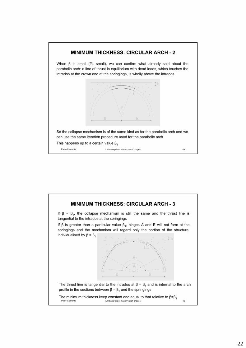
MINIMUM THICKNESS: CIRCULAR ARCH - 1
The assumption that a line of thrust touching the intrados at the crown and at the springings is wholly above the intrados is not always true in the case of a circular arch. So the mechanism of collapse may be different from the one described for the parabolic arch
For circular arch we prefer to define the geometry by means of the radius R and the angle of embrace β.
Consider the arch of fixed radius R and the series of arches obtained by increasing β
22
Paolo Clemente Limit analysis of masonry arch bridges 45
MINIMUM THICKNESS: CIRCULAR ARCH - 2
When β is small (f/L small), we can confirm what already said about the parabolic arch: a line of thrust in equilibrium with dead loads, which touches the intrados at the crown and at the springings, is wholly above the intrados
So the collapse mechanism is of the same kind as for the parabolic arch and we can use the same iteration procedure used for the parabolic arch
This happens up to a certain value β1
Paolo Clemente Limit analysis of masonry arch bridges 46
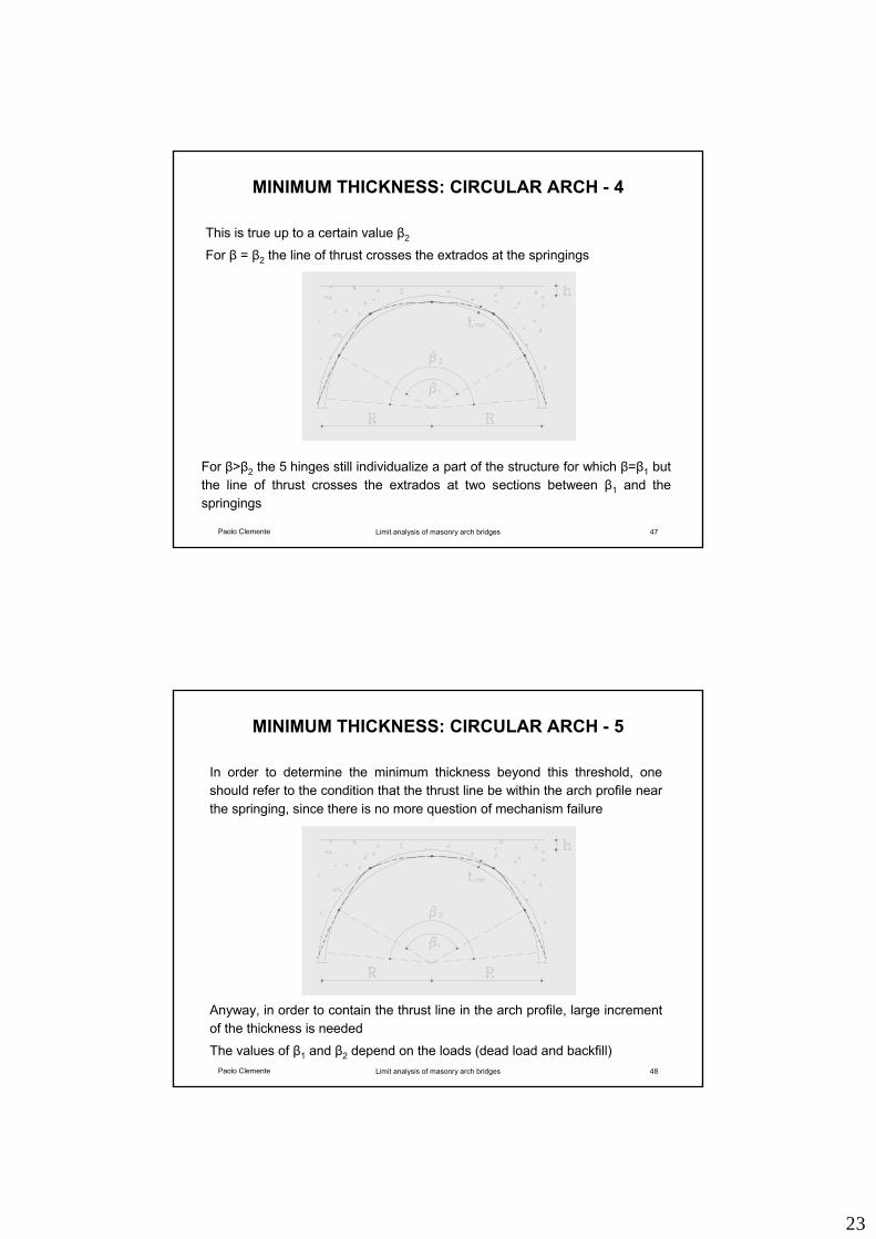
MINIMUM THICKNESS: CIRCULAR ARCH - 3
The thrust line is tangential to the intrados at β = β1 and is internal to the arch profile in the sections between β = β1 and the springings
The minimum thickness keep constant and equal to that relative to β=β1
If β = β1, the collapse mechanism is still the same and the thrust line is tangential to the intrados at the springings
If β is greater than a particular value β1, hinges A and E will not form at the springings and the mechanism will regard only the portion of the structure, individualised by β = β1
23
Paolo Clemente Limit analysis of masonry arch bridges 47
MINIMUM THICKNESS: CIRCULAR ARCH - 4
For β>β2 the 5 hinges still individualize a part of the structure for which β=β1 but the line of thrust crosses the extrados at two sections between β1 and the springings
This is true up to a certain value β2
For β = β2 the line of thrust crosses the extrados at the springings
Paolo Clemente Limit analysis of masonry arch bridges 48
MINIMUM THICKNESS: CIRCULAR ARCH - 5
Anyway, in order to contain the thrust line in the arch profile, large increment of the thickness is needed
The values of β1 and β2 depend on the loads (dead load and backfill)
In order to determine the minimum thickness beyond this threshold, one should refer to the condition that the thrust line be within the arch profile near the springing, since there is no more question of mechanism failure
24
Paolo Clemente Limit analysis of masonry arch bridges 49
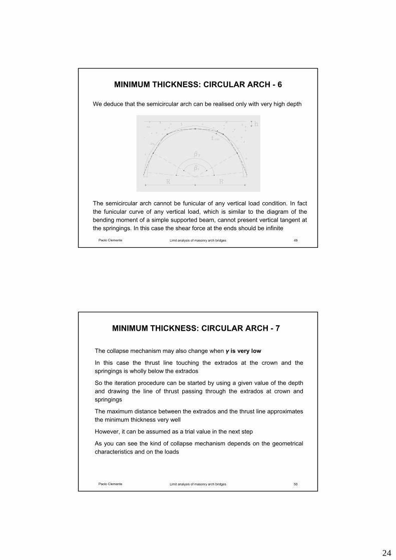
MINIMUM THICKNESS: CIRCULAR ARCH - 6
The semicircular arch cannot be funicular of any vertical load condition. In fact the funicular curve of any vertical load, which is similar to the diagram of the bending moment of a simple supported beam, cannot present vertical tangent at the springings. In this case the shear force at the ends should be infinite
We deduce that the semicircular arch can be realised only with very high depth
Paolo Clemente Limit analysis of masonry arch bridges 50
MINIMUM THICKNESS: CIRCULAR ARCH - 7
The collapse mechanism may also change when γ is very low
In this case the thrust line touching the extrados at the crown and the springings is wholly below the extrados
So the iteration procedure can be started by using a given value of the depth and drawing the line of thrust passing through the extrados at crown and springings
The maximum distance between the extrados and the thrust line approximates the minimum thickness very well
However, it can be assumed as a trial value in the next step
As you can see the kind of collapse mechanism depends on the geometrical characteristics and on the loads
25
Paolo Clemente Limit analysis of masonry arch bridges 51
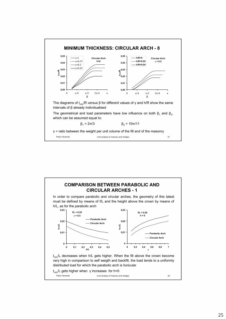
MINIMUM THICKNESS: CIRCULAR ARCH - 8
The diagrams of tmin/R versus β for different values of γ and h/R show the same intervals of β already individualised
The geometrical and load parameters have low influence on both β1 and β2, which can be assumed equal to:
β1 = 2π/3 β2 = 10π/11
γ = ratio between the weight per unit volume of the fill and of the masonry
Circular Archh=0
0,00
0,01
0,02
0,03
0,04
0,05
0 π /4 π /2 3π /4 π
β
t min
/Rγ=1γ=0.75γ=0.5γ=0.25
Circular Archγ = 0.5
0,00
0,01
0,02
0,03
0,04
0,05
0 π /4 π /2 3π /4 πβ
t min
/R
h/R=0h/R=0.02h/R=0.04
Paolo Clemente Limit analysis of masonry arch bridges 52
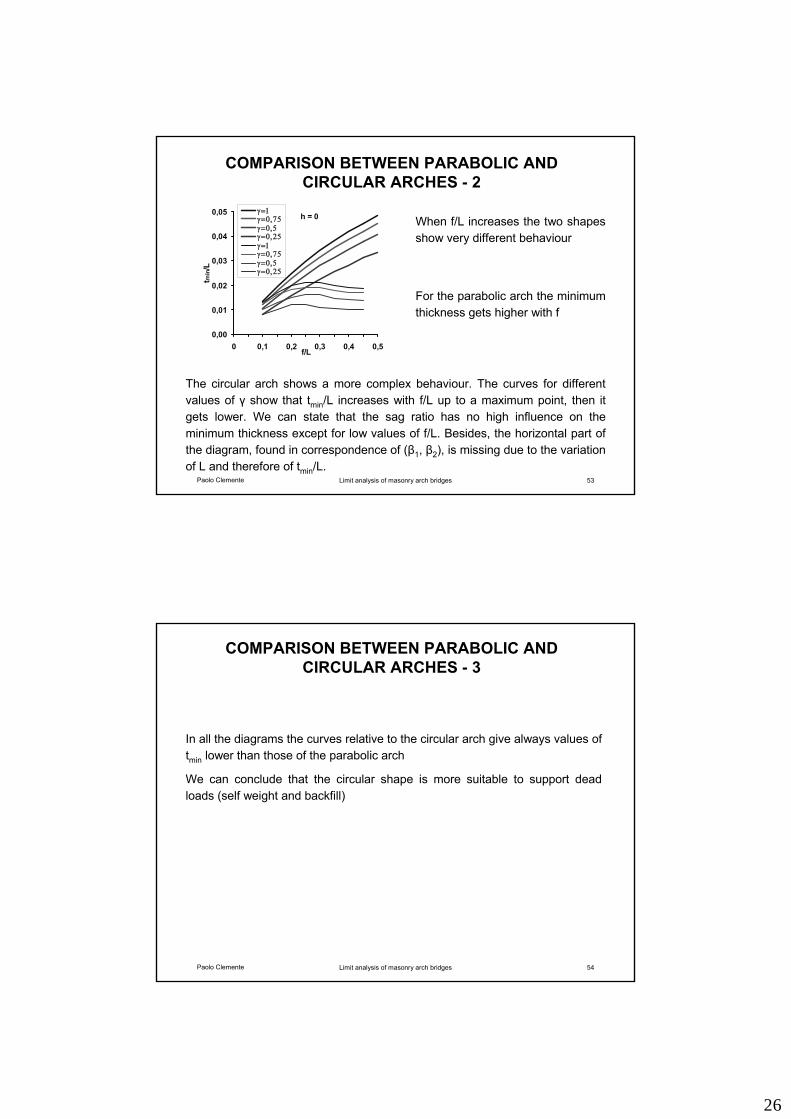
COMPARISON BETWEEN PARABOLIC AND CIRCULAR ARCHES - 1
In order to compare parabolic and circular arches, the geometry of this latest must be defined by means of f/L and the height above the crown by means of h/L, as for the parabolic arch
tmin/L decreases when h/L gets higher. When the fill above the crown become very high in comparison to self weigth and backfill, the load tends to a uniformly distributed load for which the parabolic arch is funicular
tmin/L gets higher when γ increases for h=0
f/L = 0.20γ = 0.5
0
0,01
0,02
0,03
0 0,1 0,2 0,3 0,4 0,5h/L
tmin
/L
Parabolic Arch
Circular Arch
f/L = 0.20h = 0
0
0,01
0,02
0,03
0 0,2 0,4 0,6 0,8 1γ
t min
/L
Parabolic Arch
Circular Arch
26
Paolo Clemente Limit analysis of masonry arch bridges 53
COMPARISON BETWEEN PARABOLIC AND CIRCULAR ARCHES - 2
When f/L increases the two shapes show very different behaviour
The circular arch shows a more complex behaviour. The curves for different values of γ show that tmin/L increases with f/L up to a maximum point, then it gets lower. We can state that the sag ratio has no high influence on the minimum thickness except for low values of f/L. Besides, the horizontal part of the diagram, found in correspondence of (β1, β2), is missing due to the variation of L and therefore of tmin/L.
For the parabolic arch the minimum thickness gets higher with f
h = 0
0,00
0,01
0,02
0,03
0,04
0,05
0 0,1 0,2 0,3 0,4 0,5f/L
tmin
/Lγ=1γ=0,75γ=0,5γ=0,25γ=1γ=0,75γ=0,5γ=0,25
Paolo Clemente Limit analysis of masonry arch bridges 54
COMPARISON BETWEEN PARABOLIC AND CIRCULAR ARCHES - 3
In all the diagrams the curves relative to the circular arch give always values of tmin lower than those of the parabolic arch
We can conclude that the circular shape is more suitable to support dead loads (self weight and backfill)
27
Paolo Clemente Limit analysis of masonry arch bridges 55
CHECK UNDER DEAD LOADS - 1
The structural stability under dead loads can be evaluated first, by means of locating at least one thrust line which lies wholly within the arch profile.
As already said, it is possible to estimate the minimum thickness tmin the structure needs to contain such a thrust line.
If the actual depth t is greater than tmin the structure is safe, and its lifetime will depend on the decay of the materials.
The ratio between the actual depth and the theoretical minimum one can be assumed as a measure of safety when only dead loads are acting on the masonry arch; moreover the greater α, the greater the structure will be able to carry travelling loads
ttα
min=
Paolo Clemente Limit analysis of masonry arch bridges 56
CHECK UNDER DEAD LOADS - 2
The question is the safety margin with reference to a non proportional variation of the loads but also to a reduction of the effective cross-section, due to cracks or damages to the material.
In this latest case it is meaningful to evaluate the difference
which represents the maximum crack or the maximum imperfection under dead loads
mintt −=∆
28
Paolo Clemente Limit analysis of masonry arch bridges 59
LIMIT ANALYSIS OF MASONRY ARCH BRIDGES
Limit analysis
Funicular arch
Check under dead loads
Check under moving loads
Check under horizontal actions
Paolo Clemente Limit analysis of masonry arch bridges 60
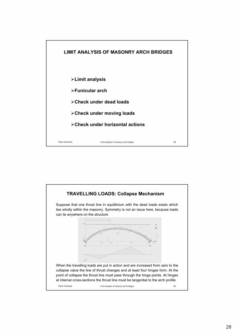
TRAVELLING LOADS: Collapse Mechanism
Suppose that one thrust line in equilibrium with the dead loads exists which lies wholly within the masonry. Symmetry is not an issue here, because loads can lie anywhere on the structure
When the travelling loads are put in action and are increased from zero to the collapse value the line of thrust changes and at least four hinges form. At the point of collapse the thrust line must pass through the hinge points. At hinges at internal cross-sections the thrust line must be tangential to the arch profile
29
Paolo Clemente Limit analysis of masonry arch bridges 61
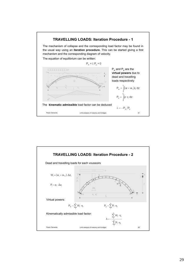
TRAVELLING LOADS: Iteration Procedure - 1
0 = P + P pw λ
( )∫ η+=L
01w dzwwP
∫ η=pz
0p dzpP
pw PP−=λ
Pw and Pp are the virtual powers due to dead and travelling loads respectively
The mechanism of collapse and the corresponding load factor may be found in the usual way using an iteration procedure. This can be started giving a first mechanism and the corresponding diagram of velocity.
The equation of equilibrium can be written:
The kinematic admissible load factor can be deduced
Paolo Clemente Limit analysis of masonry arch bridges 62
TRAVELLING LOADS: Iteration Procedure - 2
∑ ⋅=n
1iiw ηWP
Dead and travelling loads for each voussoirs
Virtual powers:
∑ ⋅=n
1iip ηPP
( ) i1iii ∆zwwW ⋅+=
iii ∆zpP ⋅=
∑
∑
⋅
⋅−= n
1ii
n
1ii
ηP
ηWλ
Kinematically admissible load factor:
∆ s
30
Paolo Clemente Limit analysis of masonry arch bridges 63
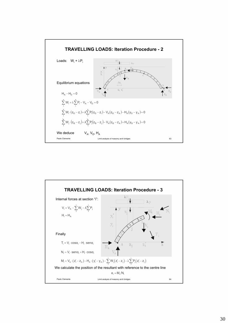
TRAVELLING LOADS: Iteration Procedure - 2
0VVPW DAii =−−λ+ ∑∑nn
11
( ) ( ) ( ) ( ) 0yyHzzVzzPλzzW ADAADAiDiiDi =−−−−−+−⋅ ∑∑nn
11
( ) ( ) ( ) ( ) 0yyHzzVzzPλzzW ABAABA
i
1jBj
i
1jBj
BB
=−+−−−+−⋅ ∑∑
0HH DA =−
Equilibrium equations
We deduce VA, VD, HA
Loads: Wi + λPi λλ
Paolo Clemente Limit analysis of masonry arch bridges 64
TRAVELLING LOADS: Iteration Procedure - 3
Internal forces at section “i”:
∑∑ −−=i
1j
i
1jAi PλWVV
Ai HH =
iiiii cosαHsenαVN ⋅+⋅=
iiiii senαHcosαVT ⋅−⋅=
( ) ( ) ( ) ( )i i
i A i A A i A j i j j i j1 1
M V z z H y y W z z P z z′ ′ ′ ′= ⋅ − − ⋅ − − − − λ −∑ ∑
iii NMe =
Finally
λλ
We calculate the position of the resultant with reference to the centre line
31
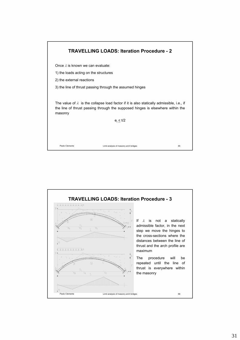
Paolo Clemente Limit analysis of masonry arch bridges 65
TRAVELLING LOADS: Iteration Procedure - 2
Once λ is known we can evaluate:
1) the loads acting on the structures
2) the external reactions
3) the line of thrust passing through the assumed hinges
The value of λ is the collapse load factor if it is also statically admissible, i.e., if the line of thrust passing through the supposed hinges is elsewhere within the masonry
ei < t/2
Paolo Clemente Limit analysis of masonry arch bridges 66
TRAVELLING LOADS: Iteration Procedure - 3
If λ is not a statically admissible factor, in the next step we move the hinges to the cross-sections where the distances between the line of thrust and the arch profile are maximum
The procedure will be repeated until the line of thrust is everywhere within the masonry
32
Paolo Clemente Limit analysis of masonry arch bridges 67
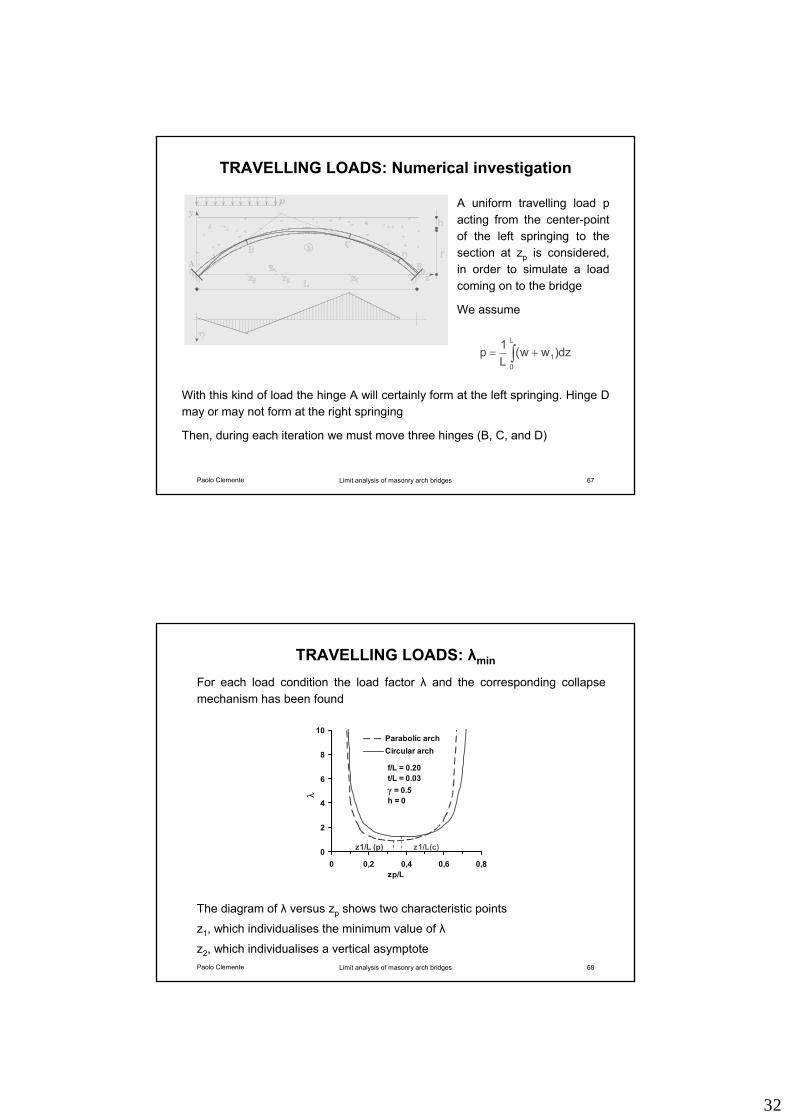
TRAVELLING LOADS: Numerical investigation
∫ +=L
01 dz)ww(
L1p
A uniform travelling load p acting from the center-point of the left springing to the section at zp is considered, in order to simulate a load coming on to the bridge
We assume
With this kind of load the hinge A will certainly form at the left springing. Hinge D may or may not form at the right springing
Then, during each iteration we must move three hinges (B, C, and D)
Paolo Clemente Limit analysis of masonry arch bridges 68
TRAVELLING LOADS: λmin
For each load condition the load factor λ and the corresponding collapse mechanism has been found
The diagram of λ versus zp shows two characteristic points
z1, which individualises the minimum value of λ
z2, which individualises a vertical asymptote
0
2
4
6
8
10
0 0,2 0,4 0,6 0,8zp/L
λ
Parabolic archCircular arch
z1/L (p) z1/L(c)
f/L = 0.20t/L = 0.03γ = 0.5h = 0
33
Paolo Clemente Limit analysis of masonry arch bridges 69
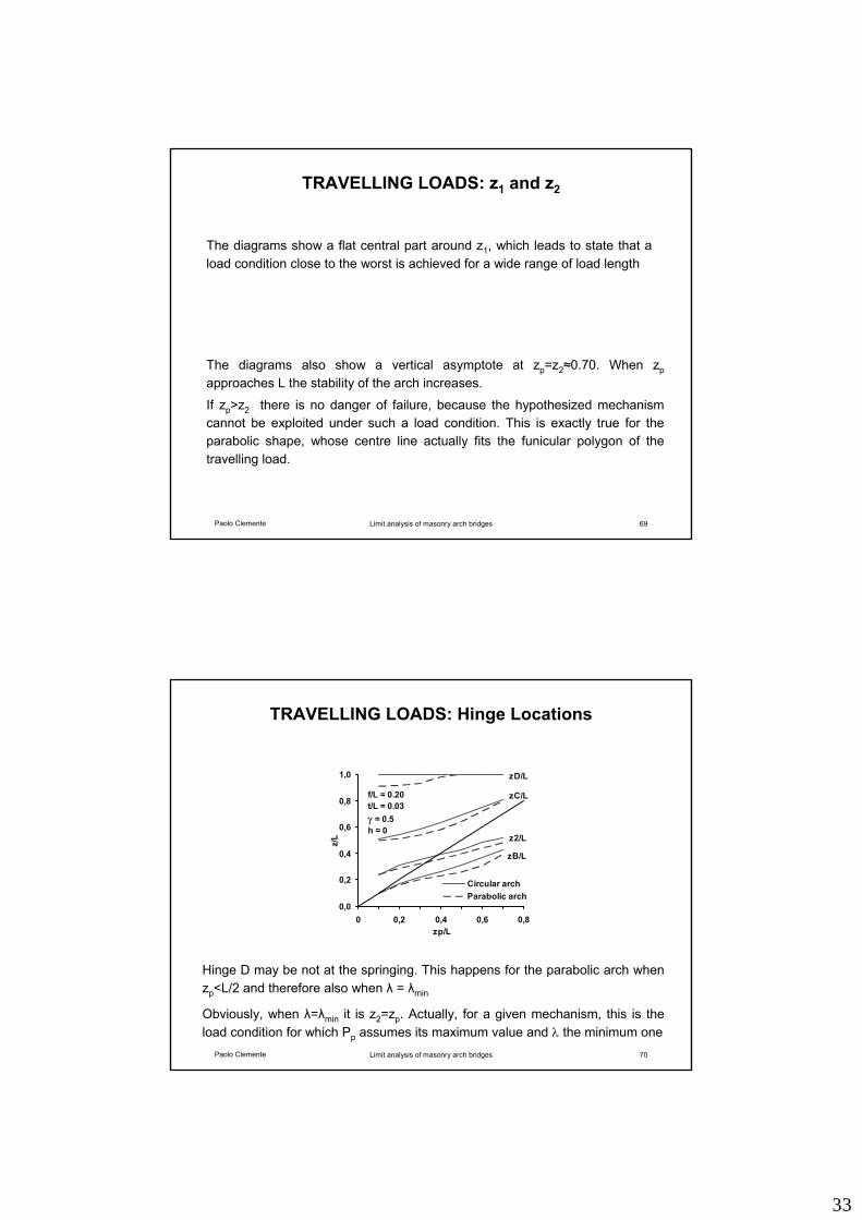
TRAVELLING LOADS: z1 and z2
The diagrams show a flat central part around z1, which leads to state that a load condition close to the worst is achieved for a wide range of load length
The diagrams also show a vertical asymptote at zp=z2≈0.70. When zpapproaches L the stability of the arch increases.
If zp>z2 there is no danger of failure, because the hypothesized mechanism cannot be exploited under such a load condition. This is exactly true for the parabolic shape, whose centre line actually fits the funicular polygon of the travelling load.
Paolo Clemente Limit analysis of masonry arch bridges 70
TRAVELLING LOADS: Hinge Locations
Hinge D may be not at the springing. This happens for the parabolic arch when zp<L/2 and therefore also when λ = λmin
Obviously, when λ=λmin it is z2=zp. Actually, for a given mechanism, this is the load condition for which Pp assumes its maximum value and λ the minimum one
0,0
0,2
0,4
0,6
0,8
1,0
0 0,2 0,4 0,6 0,8zp/L
z/L
Circular archParabolic arch
zB/L
z2/L
zC/L
zD/L
f/L = 0.20t/L = 0.03γ = 0.5h = 0
34
Paolo Clemente Limit analysis of masonry arch bridges 71
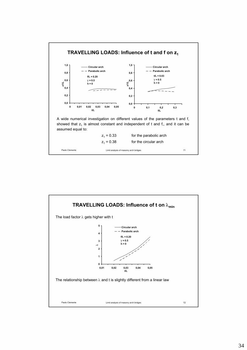
TRAVELLING LOADS: Influence of t and f on z1
A wide numerical investigation on different values of the parameters t and f, showed that z1 is almost constant and independent of t and f,, and it can be assumed equal to:
z1 = 0.33 for the parabolic arch
z1 = 0.38 for the circular arch
f/L = 0.20γ = 0.5h = 0
0,0
0,2
0,4
0,6
0,8
1,0
0 0,01 0,02 0,03 0,04 0,05t/L
z1/L
Circular archParabolic arch
t/L = 0.03γ = 0.5h = 0
0,0
0,2
0,4
0,6
0,8
1,0
0 0,1 0,2 0,3
z1/L
Circular archParabolic arch
f/L
Paolo Clemente Limit analysis of masonry arch bridges 72
TRAVELLING LOADS: Influence of t on λmin
The load factor λ gets higher with t
The relationship between λ and t is slightly different from a linear law
f/L = 0.20γ = 0.5h = 0
0
1
2
3
4
5
0,01 0,02 0,03 0,04 0,05t/L
λ
Circular archParabolic arch
35
Paolo Clemente Limit analysis of masonry arch bridges 73
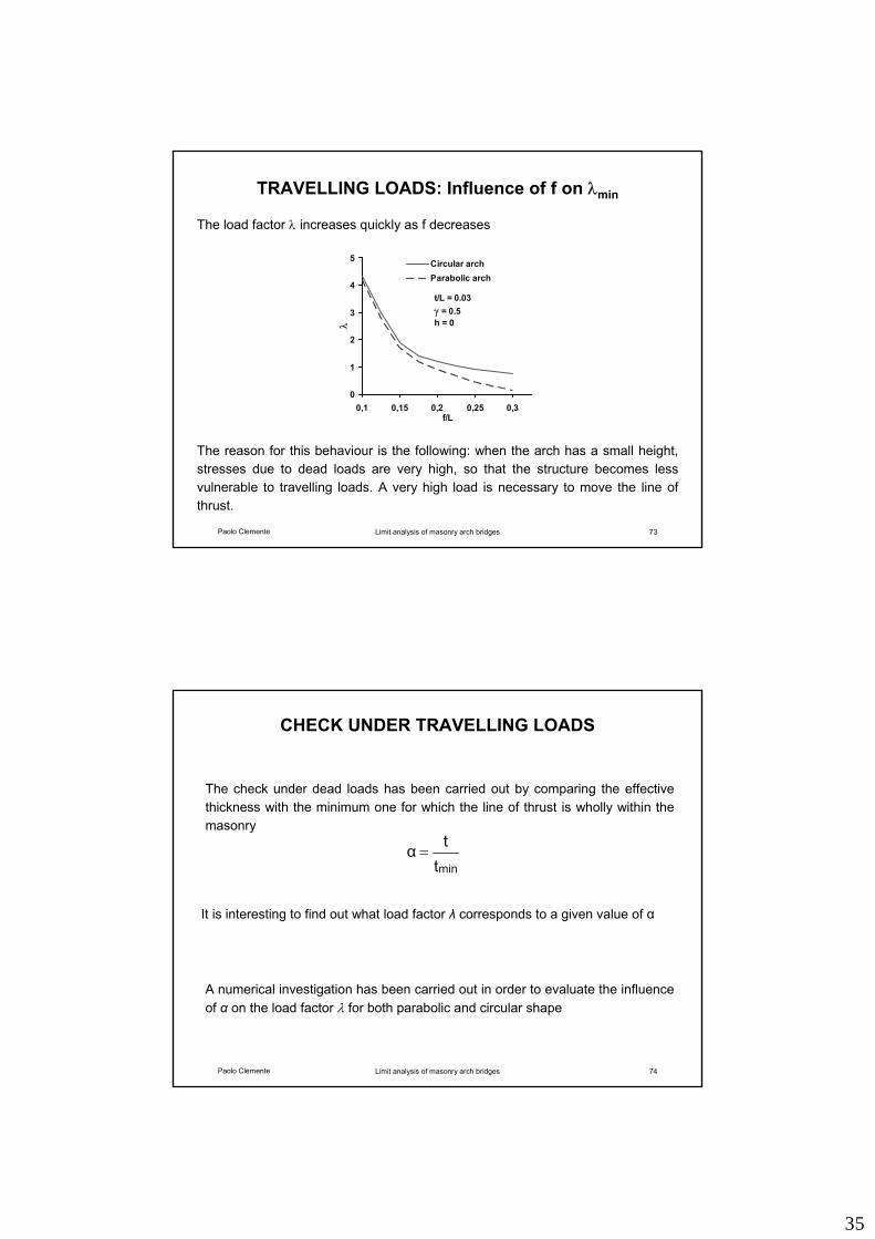
TRAVELLING LOADS: Influence of f on λmin
The reason for this behaviour is the following: when the arch has a small height, stresses due to dead loads are very high, so that the structure becomes less vulnerable to travelling loads. A very high load is necessary to move the line of thrust.
The load factor λ increases quickly as f decreases
t/L = 0.03γ = 0.5h = 0
0
1
2
3
4
5
0,1 0,15 0,2 0,25 0,3f/L
λ
Circular archParabolic arch
Paolo Clemente Limit analysis of masonry arch bridges 74
CHECK UNDER TRAVELLING LOADS
The check under dead loads has been carried out by comparing the effective thickness with the minimum one for which the line of thrust is wholly within the masonry
A numerical investigation has been carried out in order to evaluate the influence of α on the load factor λ for both parabolic and circular shape
ttα
min=
It is interesting to find out what load factor λ corresponds to a given value of α
36
Paolo Clemente Limit analysis of masonry arch bridges 75
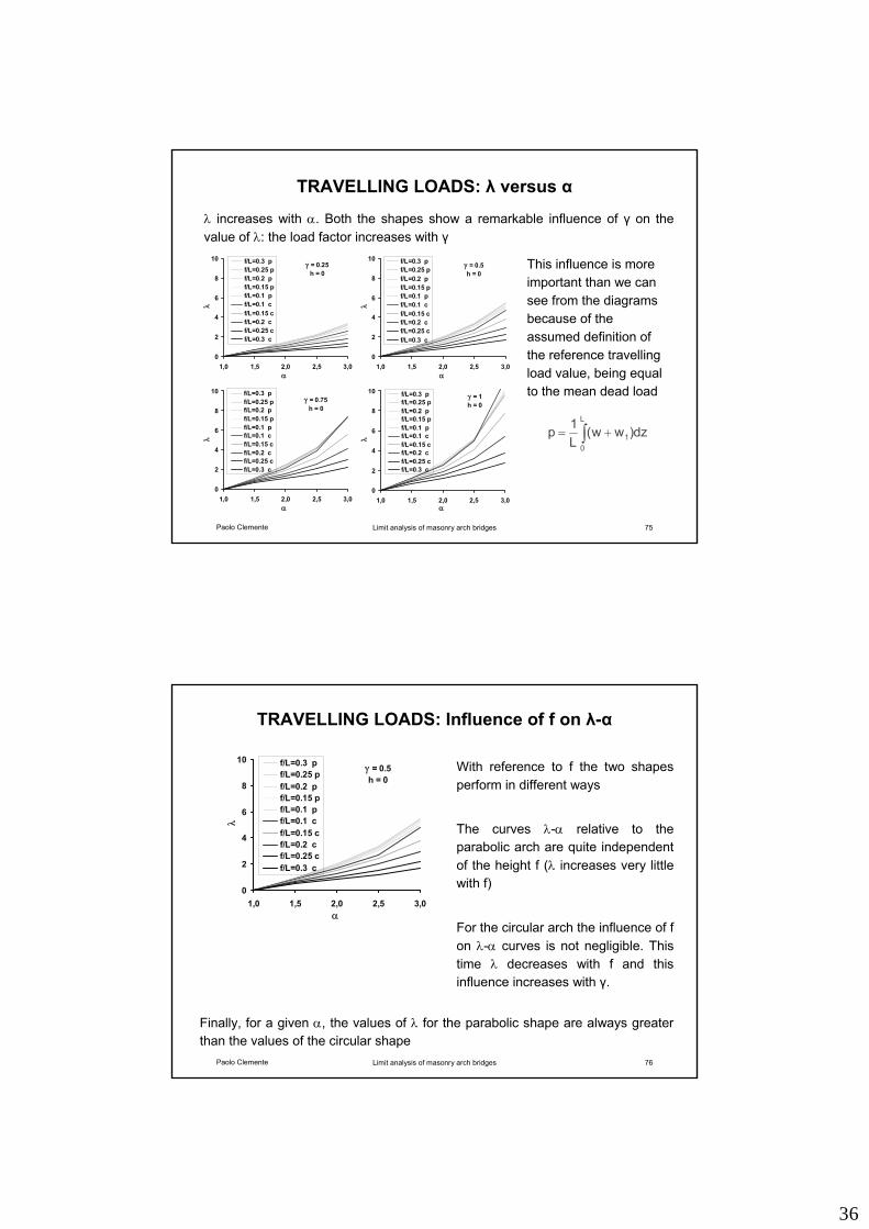
TRAVELLING LOADS: λ versus α
∫ +=L
01 dz)ww(
L1p
λ increases with α. Both the shapes show a remarkable influence of γ on the value of λ: the load factor increases with γ
This influence is more important than we can see from the diagrams because of the assumed definition of the reference travelling load value, being equal to the mean dead load
γ = 0.5h = 0
0
2
4
6
8
10
1,0 1,5 2,0 2,5 3,0α
λ
f/L=0.3 pf/L=0.25 pf/L=0.2 pf/L=0.15 pf/L=0.1 pf/L=0.1 cf/L=0.15 cf/L=0.2 cf/L=0.25 cf/L=0.3 c
γ = 0.25h = 0
0
2
4
6
8
10
1,0 1,5 2,0 2,5 3,0α
λ
f/L=0.3 pf/L=0.25 pf/L=0.2 pf/L=0.15 pf/L=0.1 pf/L=0.1 cf/L=0.15 cf/L=0.2 cf/L=0.25 cf/L=0.3 c
γ = 0.75h = 0
0
2
4
6
8
10
1,0 1,5 2,0 2,5 3,0α
λ
f/L=0.3 pf/L=0.25 pf/L=0.2 pf/L=0.15 pf/L=0.1 pf/L=0.1 cf/L=0.15 cf/L=0.2 cf/L=0.25 cf/L=0.3 c
γ = 1h = 0
0
2
4
6
8
10
1,0 1,5 2,0 2,5 3,0α
λ
f/L=0.3 pf/L=0.25 pf/L=0.2 pf/L=0.15 pf/L=0.1 pf/L=0.1 cf/L=0.15 cf/L=0.2 cf/L=0.25 cf/L=0.3 c
Paolo Clemente Limit analysis of masonry arch bridges 76
TRAVELLING LOADS: Influence of f on λ-α
With reference to f the two shapes perform in different ways
Finally, for a given α, the values of λ for the parabolic shape are always greater than the values of the circular shape
The curves λ-α relative to the parabolic arch are quite independent of the height f (λ increases very little with f)
For the circular arch the influence of f on λ-α curves is not negligible. This time λ decreases with f and this influence increases with γ.
γ = 0.5h = 0
0
2
4
6
8
10
1,0 1,5 2,0 2,5 3,0α
λ
f/L=0.3 pf/L=0.25 pf/L=0.2 pf/L=0.15 pf/L=0.1 pf/L=0.1 cf/L=0.15 cf/L=0.2 cf/L=0.25 cf/L=0.3 c
37
Paolo Clemente Limit analysis of masonry arch bridges 77
LIMIT ANALYSIS OF MASONRY ARCH BRIDGES
Limit analysis
Funicular arch
Check under dead loads
Check under moving loads
Check under horizontal actions
Paolo Clemente Limit analysis of masonry arch bridges 78
INTRODUCTION TO SEISMIC ANALYSIS - 1
The behaviour of the arch made up of rigid voussoir laid dry is very different from that of an elastic structure, especially when subject to seismic actions.
In fact, the vulnerability of an elastic structure under seismic loading is essentially related to the frequency content of the seismic input.
If the Fourier spectrum of this shows significant content at the main structural resonances, the structure is sensitive to it and may present high values of the amplification factor from the basement to the top.
Vice versa if the frequencies of the structure are not in the interval in which the seismic input spectrum shows important amplitudes, the earthquake will have not important effects on the structure
38
Paolo Clemente Limit analysis of masonry arch bridges 79
INTRODUCTION TO SEISMIC ANALYSIS - 2
The study of an arch of rigid voussoir must be performed in a very different way. Because of its infinite rigidity, a stone arch does not show relative motion with respect to its base, until the amplitude of the external load is that to turn the structure into a mechanism.
From this consideration one can deduce that the safety check of stone arches can be studied as a static problem
Paolo Clemente Limit analysis of masonry arch bridges 80
INTRODUCTION TO SEISMIC ANALYSIS - 2
If the arch is subject to the self-weight only, the horizontal forces are equal to the product between the mass of each voussoir and the horizontal acceleration and are applied at the centre gravity of each voussoir, i.e. at the same point of the vertical loads.
The structure is subjected to a parallel forces system, whose direction is determined by the ratio between the horizontal ground acceleration and the gravity acceleration.
It is as the springings of the arch were not at the same height, and the structure was fixed on a inclined plane
If the back-fill is acting on the structure the problem is quite complex. Suppose that its base is subjected to a horizontal negative acceleration
gx&&−Each voussoir is subjected to the inertial force due to its own mass, acting at the centre point of the voussoir. Four models are assumed to simulate the structure - back-fill interaction
39
Paolo Clemente Limit analysis of masonry arch bridges 81
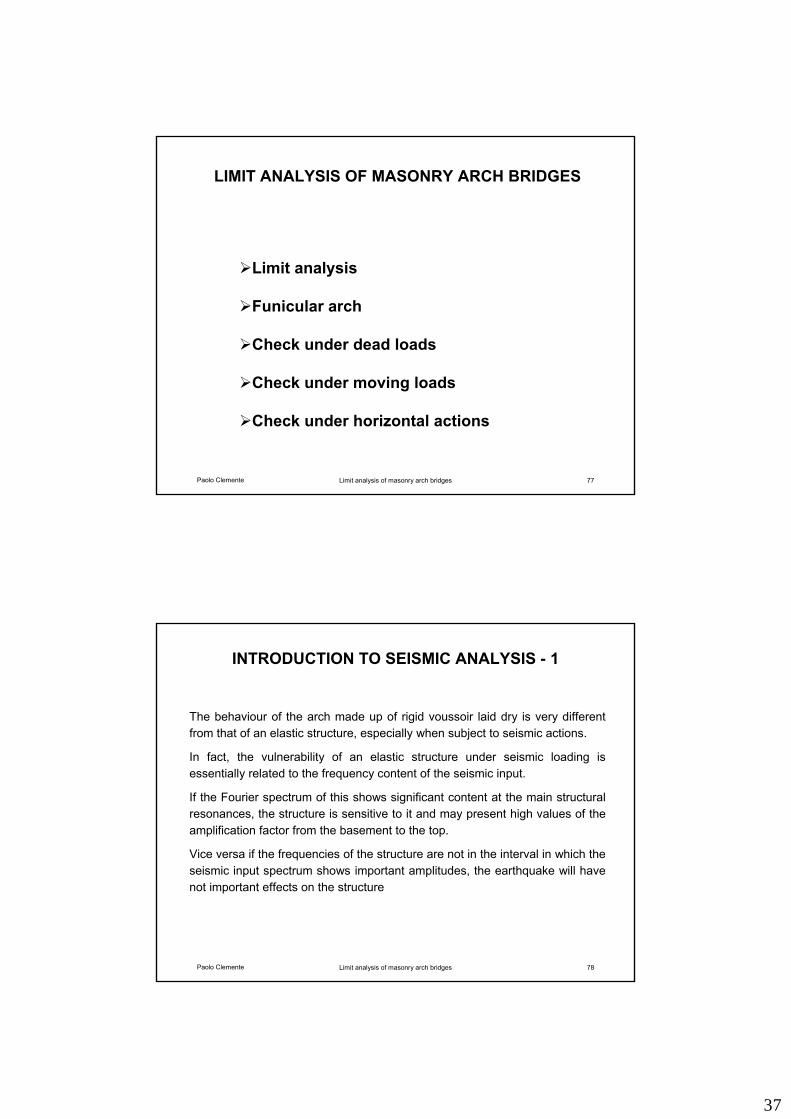
SEISMIC ACTION: Model M1
Model M1
each voussoir on the left is subjected to the inertial force due to an horizontal strip of the back-fill, and acting at its centre point. The length of this strip is assumed to be equal to the distance between the arch centre line and the vertical line passing through the left springing of the arch. The back-fill on the right tends to separate from the arch, because of its inertial forces. As a result the right half structure is subject to vertical loads and own inertial forces due to its own mass only
Paolo Clemente Limit analysis of masonry arch bridges 82
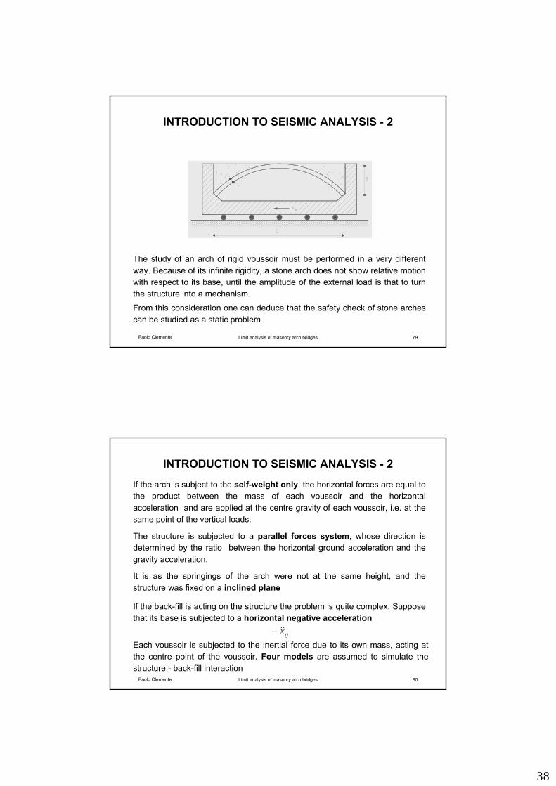
SEISMIC ACTION: Model M2
Model M2
the left half arch is loaded as in the model M1. The back-fill on the right is supposed to be attached to the structure. As a result the voussoir of the right half arch are subjected to the inertial forces due to an horizontal strip of the back-fill and acting at its centre point. The length of this strip is assumed to be equal to the distance between the centre line and the vertical line passing through the right springing
This load condition is anti-symmetric
40
Paolo Clemente Limit analysis of masonry arch bridges 83
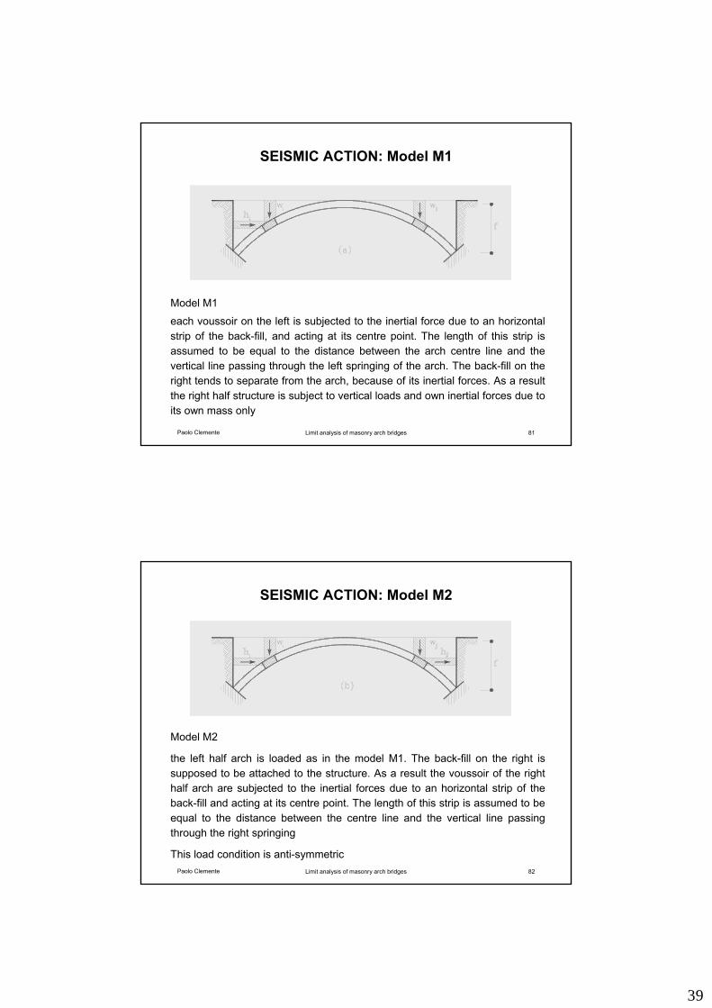
SEISMIC ACTION: Model M3
Model M3
each voussoir is subjected to an horizontal force equal to the vertical loadsacting on it
Also this load condition is anti-symmetric
Paolo Clemente Limit analysis of masonry arch bridges 84
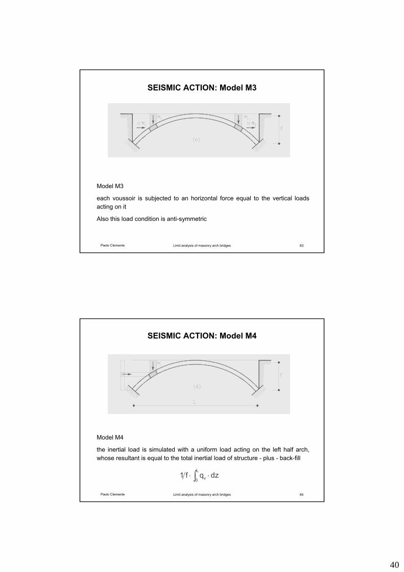
SEISMIC ACTION: Model M4
Model M4
the inertial load is simulated with a uniform load acting on the left half arch, whose resultant is equal to the total inertial load of structure - plus - back-fill
L
v01 f q dz⋅ ⋅∫
41
Paolo Clemente Limit analysis of masonry arch bridges 85
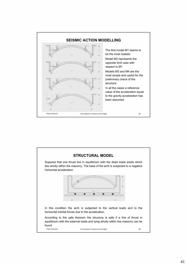
SEISMIC ACTION MODELLING
The first model M1 seems to be the most realistic
Model M2 represents the opposite limit case with respect to M1
Models M3 and M4 are the most simple and useful for the preliminary check of the structure
In all the cases a reference value of the acceleration equal to the gravity acceleration has been assumed
Paolo Clemente Limit analysis of masonry arch bridges 86
STRUCTURAL MODEL Suppose that one thrust line in equilibrium with the dead loads exists which lies wholly within the masonry. The base of the arch is subjected to a negative horizontal acceleration .
In this condition the arch is subjected to the vertical loads and to the horizontal inertial forces due to the acceleration.
According to the safe theorem the structure is safe if a line of thrust in equilibrium with the external loads and lying wholly within the masonry can be found
42
Paolo Clemente Limit analysis of masonry arch bridges 87
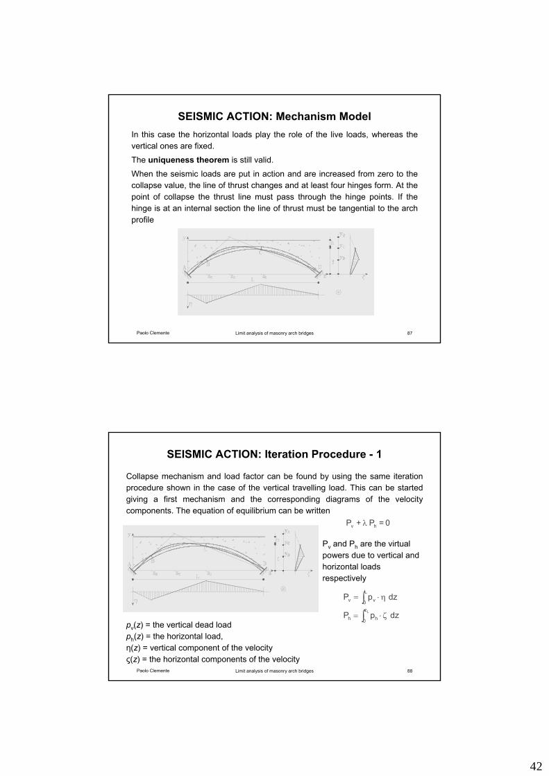
SEISMIC ACTION: Mechanism Model In this case the horizontal loads play the role of the live loads, whereas the vertical ones are fixed.
The uniqueness theorem is still valid.
When the seismic loads are put in action and are increased from zero to the collapse value, the line of thrust changes and at least four hinges form. At the point of collapse the thrust line must pass through the hinge points. If the hinge is at an internal section the line of thrust must be tangential to the arch profile
Paolo Clemente Limit analysis of masonry arch bridges 88
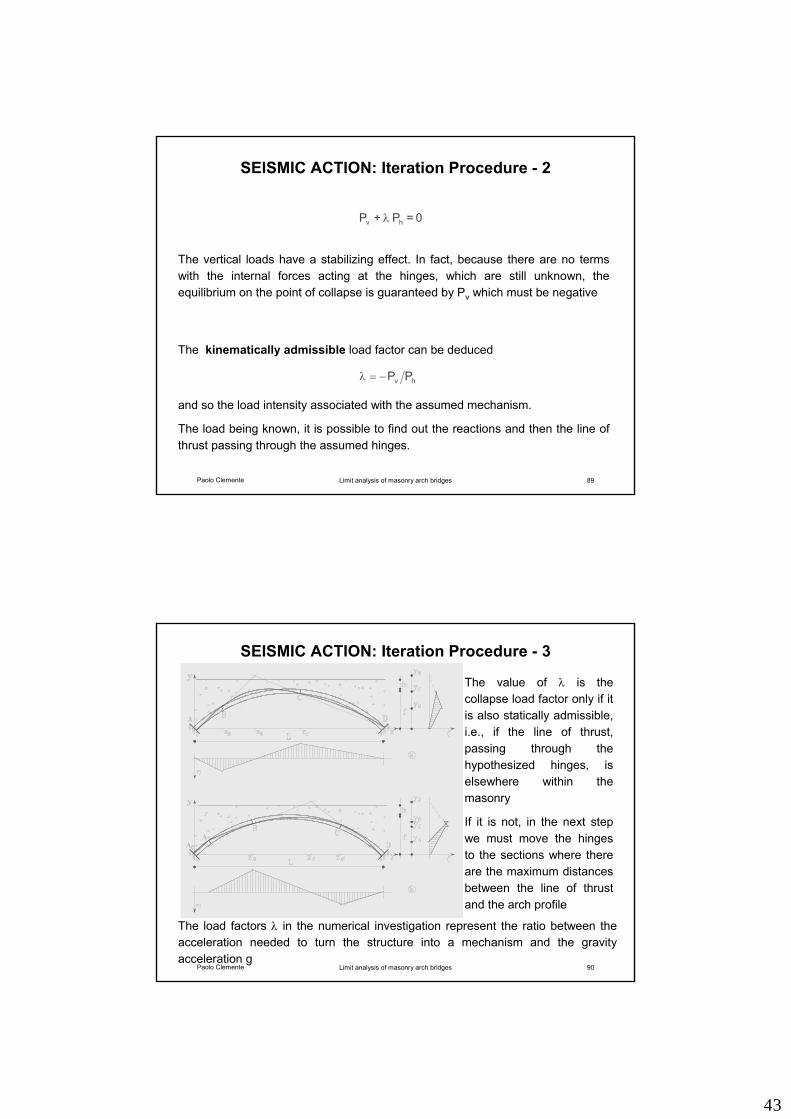
SEISMIC ACTION: Iteration Procedure - 1
Pv and Ph are the virtual powers due to vertical and horizontal loads respectively
Collapse mechanism and load factor can be found by using the same iteration procedure shown in the case of the vertical travelling load. This can be started giving a first mechanism and the corresponding diagrams of the velocity components. The equation of equilibrium can be written
0 = P + P hv λ
∫ η⋅=L
0 vv dzpP
∫ ζ⋅=Lz
0 hh dzpPpv(z) = the vertical dead load ph(z) = the horizontal load, η(z) = vertical component of the velocityς(z) = the horizontal components of the velocity
43
Paolo Clemente Limit analysis of masonry arch bridges 89
SEISMIC ACTION: Iteration Procedure - 2
The kinematically admissible load factor can be deduced
hv PP−=λ
and so the load intensity associated with the assumed mechanism.
The load being known, it is possible to find out the reactions and then the line of thrust passing through the assumed hinges.
The vertical loads have a stabilizing effect. In fact, because there are no terms with the internal forces acting at the hinges, which are still unknown, the equilibrium on the point of collapse is guaranteed by Pv which must be negative
0 = P + P hv λ
Paolo Clemente Limit analysis of masonry arch bridges 90
SEISMIC ACTION: Iteration Procedure - 3
The value of λ is the collapse load factor only if it is also statically admissible, i.e., if the line of thrust, passing through the hypothesized hinges, is elsewhere within the masonry
If it is not, in the next step we must move the hinges to the sections where there are the maximum distances between the line of thrust and the arch profile
The load factors λ in the numerical investigation represent the ratio between the acceleration needed to turn the structure into a mechanism and the gravity acceleration g
44
Paolo Clemente Limit analysis of masonry arch bridges 91
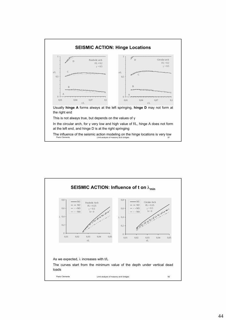
SEISMIC ACTION: Hinge Locations
Parabolic archf/L = 0.2
γ = 0.5
0
0,5
1
0,01 0,04 0,07 0,1t/L
z/L
D
B
C
A
Circular archf/L = 0.2
γ = 0.5
0
0,5
1
0,01 0,04 0,07 0,1t/L
z/L
A
D
C
B
Usually hinge A forms always at the left springing, hinge D may not form at the right end
This is not always true, but depends on the values of γ
In the circular arch, for γ very low and high value of f/L, hinge A does not form at the left end, and hinge D is at the right springing
The influence of the seismic action modeling on the hinge locations is very low
Paolo Clemente Limit analysis of masonry arch bridges 92
SEISMIC ACTION: Influence of t on λmin
As we expected, λ increases with t/L
The curves start from the minimum value of the depth under vertical dead loads
Parabolic Archf/L = 0.25
γ = 0.5h = 0
0
0,2
0,4
0,6
0,8
0,01 0,02 0,03 0,04 0,05
t/L
λ
M1M2M3M4
Circular Archf/L = 0.25
γ = 0.5h = 0
0
0,2
0,4
0,6
0,8
0,01 0,02 0,03 0,04 0,05t/L
λ
M1M2M3M4
45
Paolo Clemente Limit analysis of masonry arch bridges 93
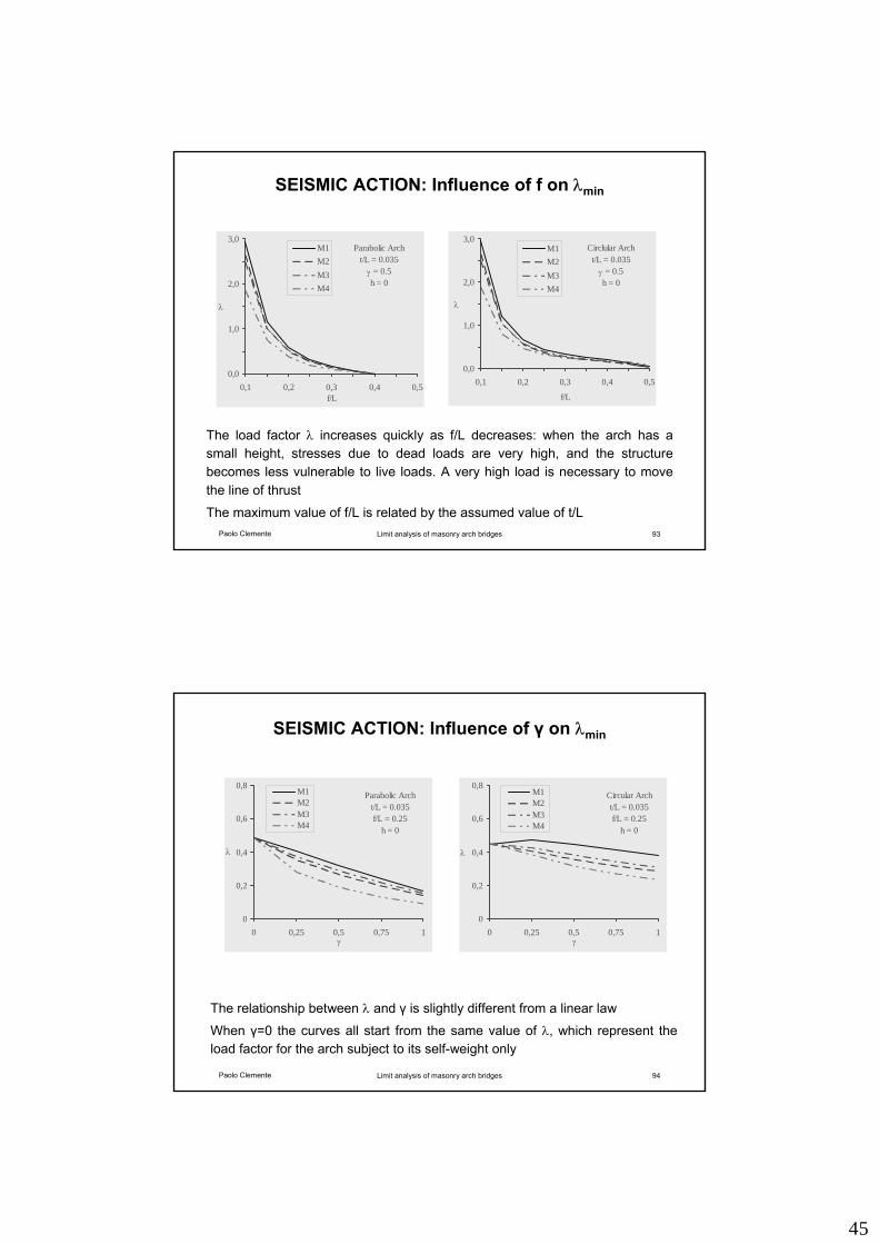
SEISMIC ACTION: Influence of f on λmin
The load factor λ increases quickly as f/L decreases: when the arch has a small height, stresses due to dead loads are very high, and the structure becomes less vulnerable to live loads. A very high load is necessary to move the line of thrust
The maximum value of f/L is related by the assumed value of t/L
Parabolic Archt/L = 0.035
γ = 0.5h = 0
0,0
1,0
2,0
3,0
0,1 0,2 0,3 0,4 0,5f/L
λ
M1M2M3M4
Circlular Archt/L = 0.035
γ = 0.5h = 0
0,0
1,0
2,0
3,0
0,1 0,2 0,3 0,4 0,5
f/L
λ
M1M2M3M4
Paolo Clemente Limit analysis of masonry arch bridges 94
SEISMIC ACTION: Influence of γ on λmin
The relationship between λ and γ is slightly different from a linear law
When γ=0 the curves all start from the same value of λ, which represent the load factor for the arch subject to its self-weight only
Parabolic Archt/L = 0.035f/L = 0.25
h = 0
0
0,2
0,4
0,6
0,8
0 0,25 0,5 0,75 1γ
λ
M1M2M3M4
Circular Archt/L = 0.035f/L = 0.25
h = 0
0
0,2
0,4
0,6
0,8
0 0,25 0,5 0,75 1γ
λ
M1M2M3M4
46
Paolo Clemente Limit analysis of masonry arch bridges 96
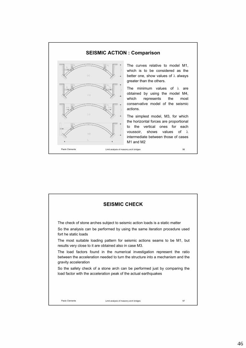
SEISMIC ACTION : Comparison
The curves relative to model M1, which is to be considered as the better one, show values of λ always greater than the others.
The minimum values of λ are obtained by using the model M4, which represents the most conservative model of the seismic actions.
The simplest model, M3, for which the horizontal forces are proportional to the vertical ones for each voussoir, shows values of λintermediate between those of cases M1 and M2
Paolo Clemente Limit analysis of masonry arch bridges 97
SEISMIC CHECK
The check of stone arches subject to seismic action loads is a static matter
So the analysis can be performed by using the same iteration procedure used fort he static loads
The most suitable loading pattern for seismic actions seams to be M1, but results very close to it are obtained also in case M3.
The load factors found in the numerical investigation represent the ratio between the acceleration needed to turn the structure into a mechanism and the gravity acceleration
So the safety check of a stone arch can be performed just by comparing the load factor with the acceleration peak of the actual earthquakes