universal verification methodology(uvm) - rf-silicon.com · universal verification methodology(uvm)...
TRANSCRIPT
Universal Verification Methodology(UVM)A Powerful Methodology for Functional Verification of Digital Hardware
Abstract - With the increasing adoption of UVM, there is a growing demand for guidelines and best practices to ensure successful SoC verification. It is true that the verification problems did not change but the way the problems are approached and the structuring of the solutions, i.e. verification environments, depends much on the methodology. There are two key categories for SoC verification guidelines: process, enabled by tools, and methodology. The process guidelines are about what you need to do and in what order, while the methodology guidelines are about how to do it. This paper will first describe the basic tenets of UVM, and then it tries to summarize key guidelines to maximize the benefits of using state of the art verification methodology such as UVM. It uses TLM standard to describe communication between verification components in a UVM environment.
INTRODUCTIONUniversal Verification Methodology(UVM) is a methodology for functional verification using System Verilog complete with a supporting library of System Verilog code. UVM environment used for the functional verification of digital hardware, primarily using simulation. The hardware or system to be verified would typically be described using Verilog, System Verilog, VHDL or SystemC at any appropriate abstraction level. This could be behavioral, register transfer level, or gate level. UVM is explicitly simulation-oriented, but UVM can also be used alongside assertion-based verification, hardware acceleration or emulation. UVM test benches are complete verification environments composed of reusable verification components, and used as part of an overarching methodology of constrained random, coverage-driven, verification.If you currently run RTL simulations in Verilog or VHDL, you can think of UVM as replacing whatever framework and coding style you use for your test benches. But UVM test benches are more than traditional HDL test benches, which might wiggle a few pins on the design-under-test (DUT) and rely on the designer to inspect a waveform diagram to verify correct operation. UVM Improves productivity and ensures re-usability. Maintenance of the verification
components will be much easier because the components are standardized . Using UVM environment a test case developer does not need to understand the full flow of the architecture.
GENERAL FEATURES OF UVM
Transaction-Level Modeling (TLM)UVM uses TLM standard to describe communication between verification components in a UVM environment. One of the main advantages of using TLM is in abstracting the pin and timing details. A transaction, the unit of information exchange between TLM components, encapsulates the abstract view of stimulus that can be expanded by a lower-level component.
Use of sequences for stimulus generationThe uvm_sequence and uvm_sequencer both provides the flexibility of running different streams of transactions without having to change the component instantiation. The transactions need to be generated by an entity in the verification environment. Relying on a component to generate the transactions is limiting because it will require changing the component each time a different sequence of transactions is required. Instead UVM allows for flexibility by introducing uvm_sequence. uvm_sequence when started, register itself with a uvm_sequencer which is an uvm_component that acts as the holder of different sequences and can connect to other uvm_components.
LayeringLayering is a powerful concept in which every level takes care of the details at specific layers. UVM layering can be applied to components, which can be called hierarchy and composition, and to configuration and to stimulus. Typically there is a correspondence between layering of components and objects. Layering stimulus, on the other hand, can reduce the complexity of stimulus generation.
Configurable Configurable, an enabler to productivity and reuse, is a key element in UVM. In UVM, user can change the behaviour of an already instantiated component by three means: configuration API, Factory overrides and callbacks.
Re-usabilityAll the tenets mentioned above lead to another important goal which is reuse. Extensibility, configurability and layering facilitate reuse. Horizontal reuse refers to reusing Verification IPs (VIPs) across projects and vertical reuse describes the ability to use block-level VIPs in cluster and chip level verification environments.
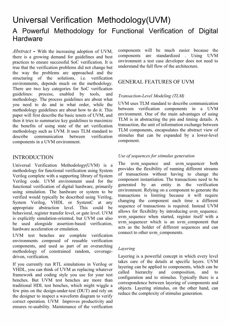
UVM Architecture
UVM TEST-BENCHuvm test, uvm env and uvm component are the three main building blocks of a test-bench in uvm based verification.
UVM Testuvm_test is derived from uvm_component class and there is no extra functionality is added. The advantage of used uvm_test for defining the user defined test is that the test case selection can be done from command line option +UVM_TESTNAME =<
testcase_string>. User can also select the testcase by passing the testcase name as string to uvm_root::run_test(<testcase_string>) method.
UVM Environmentuvm_env is extended from uvm_component. uvm_env is used to create and connect the uvm_components like driver, monitors ,sequencers. The environment (env) is the top-level component of the verification component. It contains one or more agents, as well as other components such as a bus monitor. The environment contains configuration properties that enable you to customize the topology and behavior and make it reusable. For example, active agents can be changed into passive agents when the verification environment is reused in system verification.
uvm_env is extended from uvm_component and does not contain any extra functionality. uvm_env is used to create and connect the uvm_components like driver, monitors , sequencers . A environment class can also be used as sub-environment in another environment. As there is no difference between uvm_env and uvm_component.
UVM ComponentsUVM verification component classes are derived from uvm_component class which provides features like hierarchy searching, phasing, configuration , reporting , factory and transaction recording.
Following are some of the uvm component classes :• my_agent
• my_transaction• my_sequencer
• my_driver• my_monitor
• my_scoreboard
my_agent: Sequencers, drivers, and monitors can be reused independently, but this requires the environment integrator to learn the names, roles, configuration, and hookup of each of these entities. To reduce the amount of work and knowledge required by the test writer, UVM recommends that environment developers create a more abstract container called an agent. Agents can emulate and verify DUT devices. The configurable so that they
Uvm test
Uvm env
Coverage
Predictor Comparator
Config
Analysis port
my_monitor my_driver
my_sequencer
my_agent
my_scoreboad
my_transaction
Seq_item_export
DUT
can be either active or passive. Active agents emulate devices and drive transactions according to test directives. Passive agents only monitor DUT activity.
my_transaction: User has to define a transaction by extending uvm_sequence_item. uvm_sequence_item class provides the basic functionality for objects, both sequence items and sequences, to operate in the sequence mechanism.
A complete sequence generation requires following 4 classes.1- my_transaction2- my_sequence3- my_sequencer4- my_driver
my_sequence: A sequence is a series of transaction. User can define the complex stimulus, sequences can be reused, extended, randomized, and combined sequentially and hierarchically in various ways. User should extend uvm_sequence class and define the construction of sequence of transactions. These transactions can be directed, constrained randomized or fully randomized. The uvm_sequence class provides the interfaces necessary in order to create streams of sequence items and/or other sequences.
my_sequencer: UVM sequencer is responsible for the coordination between sequence and driver. Sequencer sends the transaction to driver and gets the response from the driver. When multiple sequences are running in parallel, then sequencer is responsible for arbitrating between the parallel sequences.
my_driver: User should extend uvm_driver class to define driver component. UVM driver is a component that initiate requests for new transactions and drives it to lower level components. uvm_sequencer is connected to uvm_driver.
my_monitor: A monitor is a passive entity that samples DUT signals but does not drive them. Monitors collect coverage information and perform checking. Even though reusable drivers and sequencers drive bus traffic, they are not used for coverage and checking but monitors are used. A monitor:
• Collects transactions (sequence items): A monitor extracts signal information from a
bus and translates the information into a transaction that can be made available to other components and to the test writer.
• Extracts events: The monitor detects the availability of information (such as a transaction), structures the data, and emits an event to notify other components of the availability of the transaction. A monitor also captures status information so it is available to other components and to the test writer.
• Performs checking and coverage: Checking typically consists of protocol and data checkers to verify that the DUT output meets the protocol specification. Coverage also is collected in the monitor.
• Optionally prints trace information.
my_scoreboard: A critical component of self-checking test-benches is the scoreboard that is responsible for checking data integrity from input to output. A scoreboard checks that the DUT is behaving correctly. UVM scoreboards use analysis transactions from the monitors implemented inside agents. A scoreboard will usually compare transactions from at least two agents, which is why it is usually present in the environment. A Scoreboard operation can be summarized in the following equations:Expected = TF(Input Transaction); Compare(Actual , Expected);
TF : Transfer function representing the DUT functionality from inputs to outputs
Scoreboard operation is described as Predictor and Comparator where the predictor computes the next output (transfer function) and the comparator checks the actual versus predicted (compare function).
Predictor - A Predictor is a verification component that represents a "golden" reference model of all or part of the DUT functionality. It takes the same input stimulus that is sent to the DUT and produces expected response data that is by definition correct.
Comparator - The scoreboard evaluates the predicted activity(from predictor) with actual observed activity on the DUT.
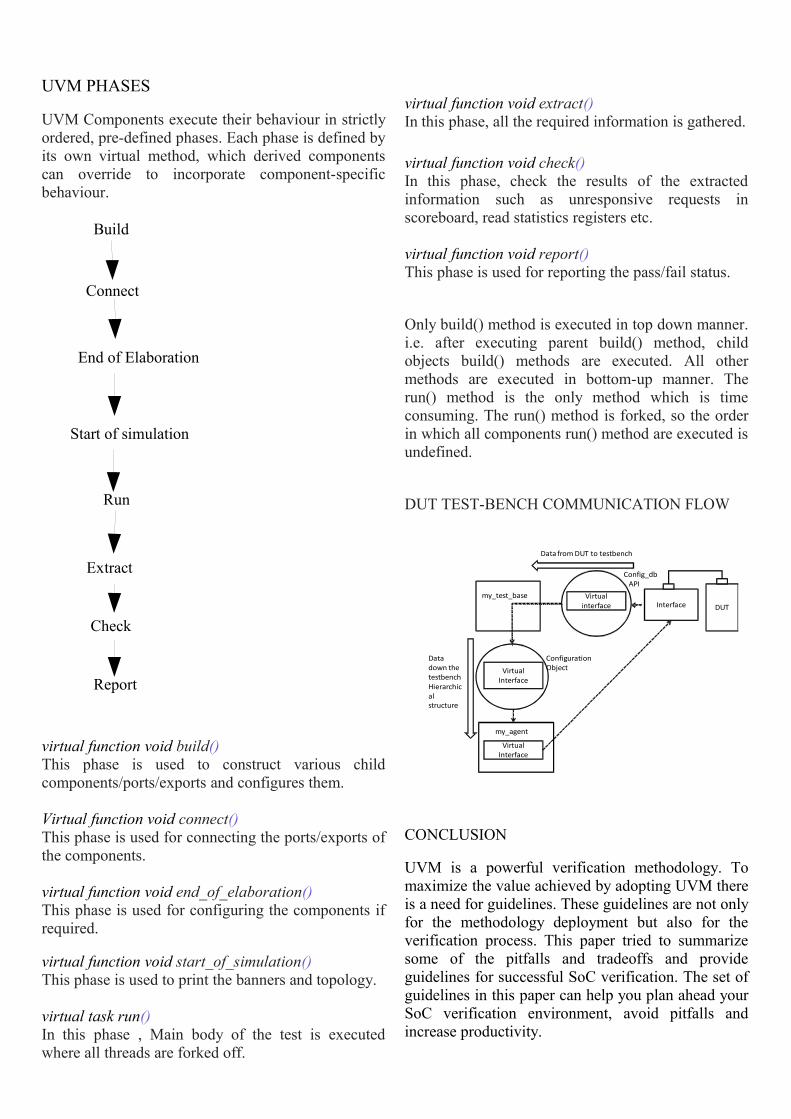
UVM PHASES
UVM Components execute their behaviour in strictly ordered, pre-defined phases. Each phase is defined by its own virtual method, which derived components can override to incorporate component-specific behaviour.
virtual function void build()This phase is used to construct various child components/ports/exports and configures them.
Virtual function void connect()This phase is used for connecting the ports/exports of the components.
virtual function void end_of_elaboration()This phase is used for configuring the components if required.
virtual function void start_of_simulation()This phase is used to print the banners and topology.
virtual task run()In this phase , Main body of the test is executed where all threads are forked off.
virtual function void extract()In this phase, all the required information is gathered.
virtual function void check()In this phase, check the results of the extracted information such as unresponsive requests in scoreboard, read statistics registers etc.
virtual function void report()This phase is used for reporting the pass/fail status.
Only build() method is executed in top down manner. i.e. after executing parent build() method, child objects build() methods are executed. All other methods are executed in bottom-up manner. The run() method is the only method which is time consuming. The run() method is forked, so the order in which all components run() method are executed is undefined.
DUT TEST-BENCH COMMUNICATION FLOW
CONCLUSION
UVM is a powerful verification methodology. To maximize the value achieved by adopting UVM there is a need for guidelines. These guidelines are not only for the methodology deployment but also for the verification process. This paper tried to summarize some of the pitfalls and tradeoffs and provide guidelines for successful SoC verification. The set of guidelines in this paper can help you plan ahead your SoC verification environment, avoid pitfalls and increase productivity.
Build
Connect
End of Elaboration
Start of simulation
Run
Extract
Check
Report
Mmymy_agentf
DUTInterfaceVirtual
interface
Virtual Interface
Virtual Interface
Configuration Object
my_test_base
Data down the testbenchHierarchicalstructure
Config_dbAPI
Data from DUT to testbench
my_agent
References1. Sasan Iman and Sunita Jushi, The e-Hardware
Verification Language, Springer 2004. 2. Mark Glasser, Open Verification
Methodology Cookbook, Springer 2009 3. Rich Edelman et al., You Are In a Maze of Twisty
Little Sequences, All Alike – or Layering Sequences for Stimulus Abstraction, DVCON 2010.
4. Victor Besyakov et al., Constrained Random Test Environment for SoC Verification using VERA, 2002.
5. OVM Register Package, www.ovmworld.org, May 18, 2010, ovm_register-2.0.
6. Accellera VIP TSC, UVM Register Modeling Requirements, www.accellera.org/activities/vip/
7. www.doulos.com