universal flow monitors, inc ... - industrial · pdf fileuniversal flow monitors, inc. 3 dtman...
TRANSCRIPT

UNIVERSAL FLOW MONITORS, INC.
DTMAN 200.2M - REV #2 - 04/14/031
See separate instructions for installing and maintaining the flow sensing portion of the unit
APPLIES TO CONTROL BOX WITH TRANSMITTER OPTIONSTT, TTV, TTL, TTZ, TTLZ, RT, RTV, RTZ, TP, RP AND REMOTEMOUNTED TRANSMITTER UT-PM-DT AND UT-PM-DTLCD.
INSTALLATION & MAINTENANCEINSTRUCTIONS FOR UFM DIGITAL
TRANSMITTERS
U N I V E R S A L
FLOW MONITORSFLOW MONITORS
R
UNIVERSAL FLOW MONITORS INC.1755 E. Nine Mile Road
Hazel Park, MI 48030-0249Ph. 248-542-9635 / Fax 248-398-4274
Email: [email protected]
See our Website for a copy of the �Warranty Statement at www.universalflow.com �
or give us a call at 248/542-9635 �to have one sent.
Contents of this Instruction Manual are applicable to instruments�shipped on or after April 15, 2003. (Ref. S/N 030400040)�
For instruments shipped on or before April 14, 2003,�see REV #1 dated 5/17/1999.
INDUSTRIAL DYNAMICS CO www.industrialdynamics.com 1-800-940-0453

UNIVERSAL FLOW MONITORS, INC.
DTMAN 200.2M - REV #2 - 04/14/03 2
TABLE OF CONTENTS
SUBJECT PAGE
DESCRIPTION................................................................................................................................................ 3
SPECIFICATIONS .......................................................................................................................................... 4
HOW IT WORKS ............................................................................................................................................ 4
WIRING ........................................................................................................................................................... 4
HAZARDOUS LOCATION WIRING ............................................................................................................... 5
INTRINSICALLY SAFE WIRING .................................................................................................................... 5
WIRING REMOTE MOUNTED TRANSMITTER ............................................................................................ 6
DC CURRENT OUTPUT WIRING .................................................................................................................. 7
OPERATING VOLTAGE REQUIREMENTS .................................................................................................. 7
OPEN COLLECTOR ALARM OUTPUT CONNECTIONS ............................................................................. 8
SETTING OPEN COLLECTOR ALARM POINTS................................................................................... 8 & 9
DIGITAL TRANSMITTER REPLACEMENT PROCEDURE................................................................. 10 & 11
CONNECTING THE REMOTE PROGRAMMER................................................................................... 11 & 12
CALIBRATION PROCEDURE ...................................................................................................................... 13
SAMPLE CALIBRATION SHEET ................................................................................................................. 14
CALIBRATION SHEET INSTRUCTIONS....................................................................................................... 15
Proprietary Notice
The information contained in this publication is derived in part from proprietary and patent data. This information
has been prepared for the expressed purpose of assisting installation, operating, and maintenance personnel in theefficient use of the instruments described herein. Publication of this information does not convey any rights to use
or reproduce it or to use for any purpose other than in connection with the installation, operation and maintenance
of the equipment described herein. Universal Flow Monitors, Inc. reserves the right to change the informationcontained in this publication at any time and without prior notice.
Copyright © 1999, UNIVERSAL FLOW MONITORS, INC.Printed in USA. All Rights Reserved,
INDUSTRIAL DYNAMICS CO www.industrialdynamics.com 1-800-940-0453

UNIVERSAL FLOW MONITORS, INC.
DTMAN 200.2M - REV #2 - 04/14/033
R Style Control Box with Transmitter Options
The "R" style control box contains a large high reso-lution analog scale and one junction box for connec-tion of transmitter and switches. This provides me-chanical flow rate indication, a 4-20 mA output signal,and optional electrical switch.
"RT": R control box with transmitter option T con-tains an analog scale and pointer for indication of flowrate, 4-20 mA output signal, and one optional electri-cal switch.
"RTV": R control box with transmitter option TVcontains an analog scale and pointer for indicationof flow rate, with either 1-5 or 2-10 VDC outputsignal, and one optional electrical switch.
"RTZ": R control box with transmitter option TZcontains an analog scale and pointer for indicationof flow rate, 4-20 mA output signal, and is ratedIntrinsically Safe. No switches are available withthis option.
T Style Control Box with Transmitter Options
The T style box has two intregral junction boxes. The oneto the right of the nameplate is for connecting to the low-voltage transmitter (NEC Class II); the one to the left is forconnecting to a mechanically-actuated micro switch (NECClass I), or to the open collector alarm outputs, if present.The micro switch may be a 3-wire or a 4-wire type. (Seeflow meter instructions for switch information.)
"TT": T control box with transmitter option T containsan analog scale and pointer for indication of flow rate, 4-20 mA output signal, and optional electrical switch(es).
"TTL": T control box with transmitter option TL containsa LCD digital display for indication of flow rate, 4-20 mAoutput signal, 2 open collector outputs with local LEDalarm indicators, and optional electrical switch(es).
"TTV": T control box with transmitter option TV con-tains an analog scale and pointer for indication of flowrate, with either 1-5 or 2-10 VDC output signal, andoptional electrical switch(es).
"TTZ": T control box with transmitter option TZ containsan analog scale and pointer for indication of flow rate, 4-20 mA output signal, and is rated Intrinsically Safe. Noswitches or open collectors are available with thisoption.
"TTLZ": T control box with transmitter option TLZcontains a LCD digital display for indication of flow rate,4-20 mA output signal, is rated Intrinsically Safe andlocal LED alarm indicators. No switches or opencollectors are available with this option.
DESCRIPTIONThis is a micro processor based flow transmitter. It provides a 2-wire linear 4-20mA dc output signal. High accuracyis assured by individual calibration. Reliability is assured by high temperature burn-in of the circuit boards. Thetransmitter is commonly supplied in the control box of the flowmeter along with the driving potentiometer. There aretwo styles of control boxes "T" & "R" (shown below).
The transmitter has been CE certified for general purpose locations, CSA NRTL/C for Non-Hazardous locations andHazardous locations with an Intrinsically Safe Barrier. Wiring must be in accordance with Control Drawing #7079 andarticle 504 of NEC, ANSI NPF 70 (Fig. 1, pg. 5). Applicable Symbols for Intrinsically Safe (I.S.) versions are TTZ, TTLZand RTZ.
INDUSTRIAL DYNAMICS CO www.industrialdynamics.com 1-800-940-0453

UNIVERSAL FLOW MONITORS, INC.
DTMAN 200.2M - REV #2 - 04/14/03 4
WIRING
Connect a twisted wire pair (not provided) to the termi-nals marked + and - in the right-hand junction box. Thewire may be up to AWG 12 size, but no smaller than AWG22. An electrical ground connection may be made to theground screw provided in the box. If shielded cable isused the shield may also be grounded here. (See Fig. 3,Pg. 7).
The twisted wire pair connects the transmitter and allreceiving equipment in a loop. Wire length of up to 1000feet is acceptable if the wire is kept dry and distant fromelectrical noise sources. The receiving equipment mustaccept industry-standard 4-20 mA transmitter input.Supply power (typically 24 VDC at 30 mA) must besupplied by one of the receiving units (such as a recorderor controller) or by a separate power supply, as shown asFig. 3, Pg. 7. While the transmitter is rated for supplyvoltages of 10-30 VDC, it can handle up to 39 volts, butwill degrade signal accuracy and damage will occurabove 39 VDC.
Several receivers may be connected in series, but onlyone power supply source should be used. All shouldhave isolated inputs.
The supply voltage provided must be within the limitsshown in Fig. 4, Pg. 7, which requires you calculate totalloop resistance. To do this simply add up the resistanceof all the receivers, indicators, and wire in the loop. If wireresistance is unknown, use a value of 50 ohms for up to1000 feet of twisted wire pair.
All loop shields should be grounded, at only one end,either the transmitter(s) or receivers(s). Some receivingequipment inputs are grounded when they’re manufac-tured. You can utilize this; but only one receiver per loop.
HOW IT WORKS
A precision potentiometer is attached to the springloaded shaft of the flow meter. As this shaft is causedto rotate, due to flow, it turns the potentiometer shaft.The potentiometer output is a non-linear voltage vary-ing with changes in flow. The transmitter conditionsthe voltage input from the potentiometer providing alinear 4-20 mA signal proportional to flow. For receiv-ers that require a 1 to 5, or 2 to 10 VDC input the usermay install a precision 250 ohm or 500 ohm resistor,0.1%, 1/2-W respectively, between signal input andcommon of the receiver.Note: The transmitter and flowmeter are suppliedfactory calibrated. Recalibration is necessary if thetransmitter is replaced or if the flowmeter is rebuilt orrepaired. Consult Factory for instructions.
SPECIFICATIONS
Input power10-30 VDC @ 21 mA (24 VDC Max. for IntrinsicallySafe)Output4-20 mA DC Linear (2-Wire Transmitter)V Option 1-5 VDCY Option 2-10 VDCMaximum Output Current21mAPot Voltage1.25 VDCOperating Temperature0∞F +176∞F (-18∞C to +80∞C)Response Time250 MillisecondsCalibrated AccuracySame as primary device. Electrical Accuracy = +/-1% of FS (over entire range of operation)Temperature Effect on AccuracyNo effect on Electrical AccuracyOutput Noise0.5% FS peak-to-peak, 0.25% FS RMSDisplay Type4 1/2 Digit 7-segment LCD, 0.30" digit heightAlarm Outputs2 opto-isolated open-collector PNP transistors withcorresponding LEDs (for Low & High Flowrate).Alarm Output Rating(Open Collectors)50 mA per output at 30 VDCData RetentionEEPROM (40 years)Approvals/CertificationCSA (NRTL/C), Intrinsically Safe for all Classes andGroups of hazardous locations and CE.Board Dimensions1.15"W x 2.75"L x 0.50"H (including LCD)
INDUSTRIAL DYNAMICS CO www.industrialdynamics.com 1-800-940-0453
3
4
1
2-
++
-
+
-
(+)
(-)
(CHASSIS)
SPECIAL CONDITION FOR SAFE USE IN HAZARDOUS LOCATIONS (CENELEC CONDITION "X"):THESE UFM DEVICES DO NOT HAVE THE REQUIRED 500 V ISOLATION BETWEEN THE CIRCUITS AND THE CASE. ON INSTALLATION, THE CASEMUST EITHER BE ISOLATED FROM GROUNDED SURFACES, OR BE AT THE SAME POTENTIAL AS THE I.S. BARRIER GROUND.
6. I.S. BARRIER OR ASSOCIATED DEVICE CONNECTED TO THIS EQUIPMENT MUST MEET THE FOLLOWING REQUIREMENTS:
5. INSTALL IN ACCORDANCE WITH THE CANADIAN ELECTRICAL CODE, PART 1 FOR INSTALLATION IN CANADA, OR WITH THE NEC (ANSI/NFPA 70) AND ANSI/ISA RP12.6 FOR INSTALLATION IN U.S.
4. THE RESISTANCE FROM THE FURTHEST I.S. BARRIER GROUND TO THE DESIGNATED GROUND ELECTRODE MUST NOT EXCEED 1 OHM.
2. BARRIERS MUST BE CSA CERTIFIED FOR INSTALLATION IN CANADA, NRTL APPROVED FOR INSTALLATION IN U.S., OR CENELEC APPROVED FOR INSTALLATION IN EUROPE, AND MUST BE INSTALLED IN ACCORDANCE WITH MANUFACTURERS INSTRUCTIONS.3. MAXIMUM NON-HAZARDOUS AREA VOLTAGE MUST NOT EXCEED 250V.
1. I.S. BARRIER ENTITY PARAMETERS: VMAX=28 VOLTS, IMAX=69mA, CI=.012uFD, LI=100uH
VOC ≤ VMAXISC ≤ IMAXCA ≥ CI + CCABLELA ≥ LI + LCABLE
I.S. BARRIER NOTES:
G-BOX METERS MODELS GTL, GTLZ, GPLR, & UT-PM-DTLCDMODULAR SENSOR MANIFOLD MODEL MSM &
CLASS III HAZARDOUS LOCATIONSCLASS II GROUPS E, F & G
CSA/NRTL: CLASS I GROUPS A,B,C &D
UFM DEVICES SUITABLE FOR USE IN:
EUROPEAN EExia: IIC T4
TO UFM DEVICE:
SUPPLYPOWER24 VDC
THE POWER SUPPLY CONTROL
THAN 250 VOLTS.ABLE TO GENERATE MOREUNIT MUST NOT USE OR BE
I.S. GROUND
250 OHMS MAX.
I.S. BARRIERMFR: R. STAHL
MODEL: 9001/01-280-75-10
SAFE AREAHAZARDOUSAREA LOAD
LOAD4-20 mA
Ref: Drawing 7079B08
UNIVERSAL FLOW MONITORS, INC.
DTMAN 200.2M - REV #2 - 04/14/035
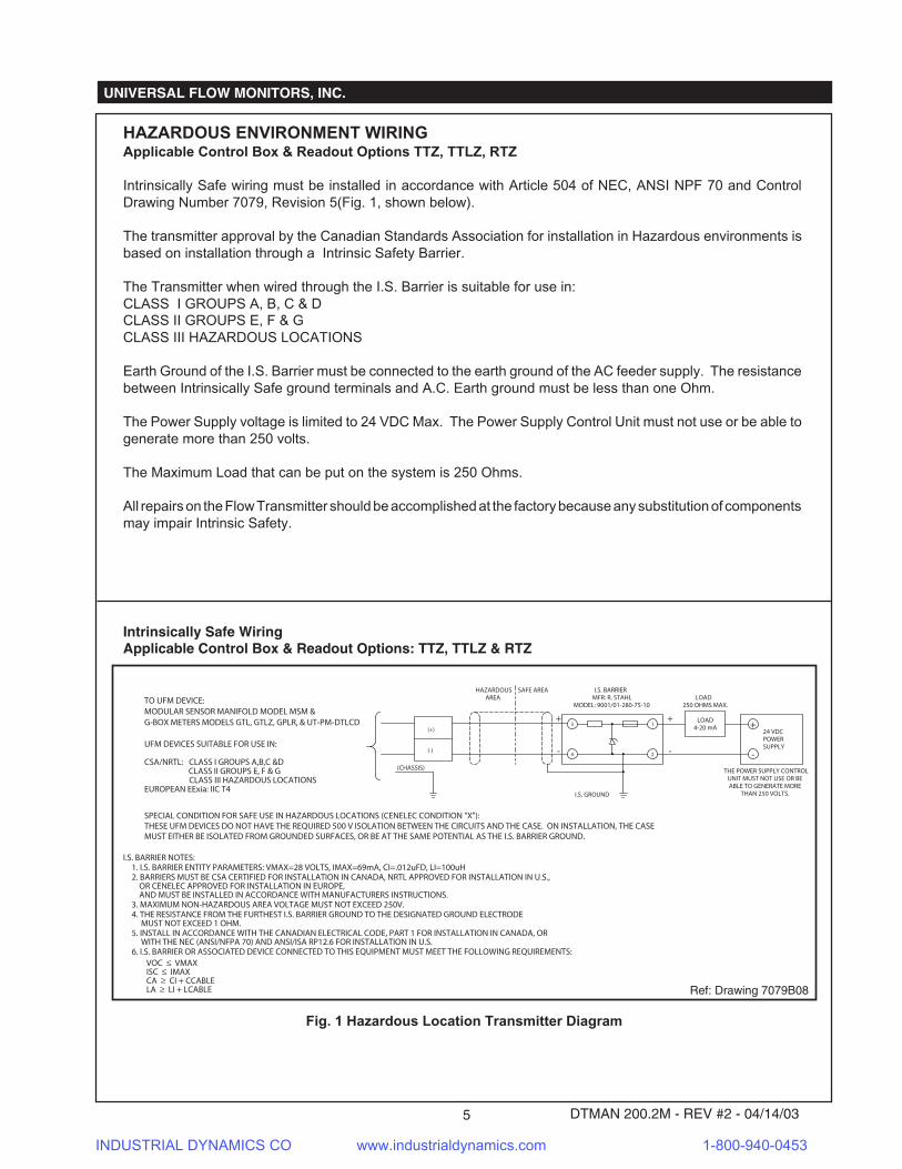
HAZARDOUS ENVIRONMENT WIRINGApplicable Control Box & Readout Options TTZ, TTLZ, RTZ
Intrinsically Safe wiring must be installed in accordance with Article 504 of NEC, ANSI NPF 70 and ControlDrawing Number 7079, Revision 5(Fig. 1, shown below).
The transmitter approval by the Canadian Standards Association for installation in Hazardous environments isbased on installation through a Intrinsic Safety Barrier.
The Transmitter when wired through the I.S. Barrier is suitable for use in:CLASS I GROUPS A, B, C & DCLASS II GROUPS E, F & GCLASS III HAZARDOUS LOCATIONS
Earth Ground of the I.S. Barrier must be connected to the earth ground of the AC feeder supply. The resistancebetween Intrinsically Safe ground terminals and A.C. Earth ground must be less than one Ohm.
The Power Supply voltage is limited to 24 VDC Max. The Power Supply Control Unit must not use or be able togenerate more than 250 volts.
The Maximum Load that can be put on the system is 250 Ohms.
All repairs on the Flow Transmitter should be accomplished at the factory because any substitution of componentsmay impair Intrinsic Safety.
Intrinsically Safe WiringApplicable Control Box & Readout Options: TTZ, TTLZ & RTZ
Fig. 1 Hazardous Location Transmitter Diagram
INDUSTRIAL DYNAMICS CO www.industrialdynamics.com 1-800-940-0453

UNIVERSAL FLOW MONITORS, INC.
DTMAN 200.2M - REV #2 - 04/14/03 6
WIRING REMOTE MOUNTED TRANSMITTER WITH 4-20 mA OUTPUTApplicable Control Box & Readout Options TP & RP
Note: The transmitter must be matched by the Serial Number to the meter, for which it has been calibrated.The TP or RP control box utilizes a Potentiometer for converting motion to a voltage output. Connect a twisted3-wire shielded cable between the TP or RP control box and the transmitter, grounding the shield at only one end.
The potentiometer will be wired to a terminal strip inside the right electrical ear of the TP or RP control box. Therewill be a diagram affixed to the inside of the right cover plate identifying which terminal is the CCW, W and CWconnection.
NOTE: Shielded cable may be run in conduit with other low level signals but may not be run in conduit with 110V.A.C. or other power wiring. Shielded cable may not be run in conduit with pulse signals.
Supply power requirement (typically 10 - 30 VDC @ 21 mA) must be supplied by one of the receiving units (suchas a recorder or controller) or by a separate power supply, as shown in Fig. 2, below.
Several receivers may be connected in series, but only one power supply source should be used. All receiversshould have isolated inputs.
The Negative connection, for the loop, goes to terminal with black wire on the transmitter and the Positiveconnection goes to terminal with red wire as shown in Fig. 2, below.
The 3-wire shielded cable will connect the terminal strip in the control box to the transmitter. (Fig. 2, below).
Fig. 2 Remote Mounted 4-20 mA Transmitter Wiring
Remote Mounted Transmitter WiringApplicable Control Box & Readout Options: TP & RP
1(CCW)
2(W)
3(CW) WHT/BLK
CCW
RED/BLKW
GRNCW
}4-20 mALOOP
REMOTETRANSMITTER
FLOWXMTR
EARTHGROUND
- + + -
RED(+)
BLK(-)
RECEIVERPOWER SUPPLY(CAN BE PART OF A RECEIVER)
AC IN
ELECTRICAL (RIGHT) EAROF CONTROL BOX
IN LINECONN.
(UT-PM-DT or UT-PM-DTLCD)
INDUSTRIAL DYNAMICS CO www.industrialdynamics.com 1-800-940-0453
UNIVERSAL FLOW MONITORS, INC.
DTMAN 200.2M - REV #2 - 04/14/037
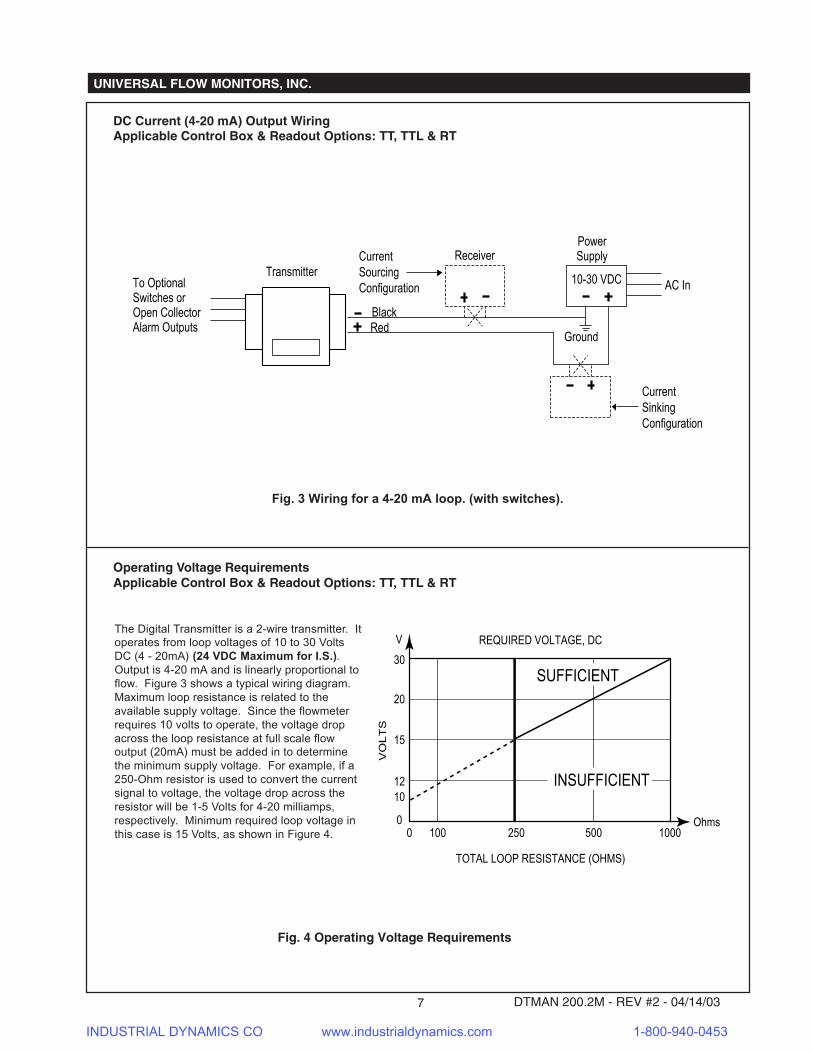
DC Current (4-20 mA) Output WiringApplicable Control Box & Readout Options: TT, TTL & RT
Fig. 3 Wiring for a 4-20 mA loop. (with switches).
Fig. 4 Operating Voltage Requirements
Current SinkingConfiguration
PowerSupply
Transmitter
Red
AC In
Black
10-30 VDC
Receiver
Ground
Current SourcingConfigurationTo Optional
Switches orOpen CollectorAlarm Outputs
Operating Voltage RequirementsApplicable Control Box & Readout Options: TT, TTL & RT
The Digital Transmitter is a 2-wire transmitter. Itoperates from loop voltages of 10 to 30 VoltsDC (4 - 20mA) (24 VDC Maximum for I.S.).Output is 4-20 mA and is linearly proportional toflow. Figure 3 shows a typical wiring diagram.Maximum loop resistance is related to theavailable supply voltage. Since the flowmeterrequires 10 volts to operate, the voltage dropacross the loop resistance at full scale flowoutput (20mA) must be added in to determinethe minimum supply voltage. For example, if a250-Ohm resistor is used to convert the currentsignal to voltage, the voltage drop across theresistor will be 1-5 Volts for 4-20 milliamps,respectively. Minimum required loop voltage inthis case is 15 Volts, as shown in Figure 4.
REQUIRED VOLTAGE, DC
TOTAL LOOP RESISTANCE (OHMS)
VO
LT
S
0 100 250 500 1000
15
0
10
20
30
INSUFFICIENT
SUFFICIENT
12
V
Ohms
INDUSTRIAL DYNAMICS CO www.industrialdynamics.com 1-800-940-0453

UNIVERSAL FLOW MONITORS, INC.
DTMAN 200.2M - REV #2 - 04/14/03 8
Open Collector Alarm Output ConnectionsApplicable Control Box & Readout Options: TTL
Fig. 5 Open Collector Alarm Output Connections(Shown for Typical Relay Installation)
External Flyback Diode 1N4002
+24 VDC
ExternalRelay
Alarm Output 1 (high alarm / blue)
Digital Transmitter (internal circuit)
Alarm Output Connection
Alarm Output 2 (low alarm / orange)
+24 VDC
ExternalRelay
External Flyback Diode1N4002
*NOTE 1: Maximum load voltage of open collector contact is 50 mA @ 30 volts DC.
-24 VDC Alarm Common (white)
ADJUSTA1
ENT./SETA2
ALARM 1
ALARM 2
Adjust/A1
Ent/Set/A2
HFLOTo Set High Alarm:
Push Adjust/A1.Hold until display reads 'HFLo', thenchanges to 'Set',
then release Adjust/A1.
To Set Low Alarm:Push Ent/Set/A2.Hold until display reads 'LFLo', thenchanges to 'Set',
then release Ent/Set/A2.
When done, push and holdEnt/Set/A2. Display will read
'Set' and flash the new setpoint. Release button.
Use Ent/Set/A2 button toselect digit to be changed.
Then use Adjust/A1 to change it's value.
Setting Open Collector Alarm PointsApplicable Control Box & Readout Options: TTL & UT-PM-DTLCD
Fig. 6 Setting Open Collector Alarm Points
INDUSTRIAL DYNAMICS CO www.industrialdynamics.com 1-800-940-0453

UNIVERSAL FLOW MONITORS, INC.
DTMAN 200.2M - REV #2 - 04/14/039
SETTING OPEN COLLECTOR ALARM POINTSApplicable Control Box & Readout Options TTL & UT-PM-DTLCD
High Alarm Programming mode is entered using the ADJUST-A1 button. Low alarm programming mode isentered using the ENT/SET-A2 button. (See Fig. 6, pg. 8)
1. To enter high alarm programming mode, press and hold the A1 button. The transmitter will display"HFLo" for 2 seconds followed by "SEt". Release the A1 button.
2. The transmitter will display a 4 digit value with the first digit blinking. To adjust this digit, press theADJUST button to cycle from 0-9 and back to 0. To enter the value and cycle to the next digit,press and release the ENT/SET button.
Repeat step 2 for the subsequent digits. After the most significant digit is entered, hold down the ENT/SETbutton until "SEt" is displayed, and then release the button. The transmitter will display "SEt" for 1 second.It will then flash the calibrated high alarm value 2 times before exiting to run mode.
Note: If it is required to go back and change any of the digits, press and immediately release the ENT/SET button after the most significant digit is adjusted. The calibration will cycle back to the leastsignificant digit.
3. To enter the low alarm programming mode, press and hold the A2 button. The transmitter willdisplay "LFLo" for 2 seconds followed by "SEt. Release the A2 button.
4. Follow the instructions in steps 2 for programming the low alarm.
Note: While in alarm programming mode the transmitter is not monitoring flow. To prevent this conditionfrom occurring for an extended period of time, there is a 20 second time limit for programminginactivity; i.e., no switches being pushed. If this time limit is exceeded then alarm programming isautomatically exited with no change to any previous programming.
ALARM SETTING LIMITATIONS
While it is possible for the user to input any 4 digit value in either high or low alarm programming mode, thetransmitter is designed not to store values greater than 125% of the full scale display value for high alarmsettings. The transmitter is also designed not to store values greater than 100% of the full scale displayvalue for the low alarm settings. In the event of an invalid alarm value the transmitter defaults to an alarmsetting equal to 125% of the full scale display value for high alarms or 100% of the full scale display valuefor low alarms. This value will then flash 2 times before exiting alarm programming mode.
Example 1: Invalid High Alarm Setting100 gpm flow meter;User inputs 150 for the high alarm setting;Upon exiting high alarm programming mode, the value 125 flashes 2 times, indicating that thestored high alarm setting has defaulted to 125 gpm (125% of the full scale display value).
Example 2: Invalid Low Alarm Setting100 gpm flow meter;User inputs 110 for the low alarm setting;Upon exiting low alarm programming mode the value 100 flashes 2 times, indicating that thestored low alarm setting has defaulted to 100 gpm (100% of the full scales display value).
INDUSTRIAL DYNAMICS CO www.industrialdynamics.com 1-800-940-0453

UNIVERSAL FLOW MONITORS, INC.
DTMAN 200.2M - REV #2 - 04/14/03 10
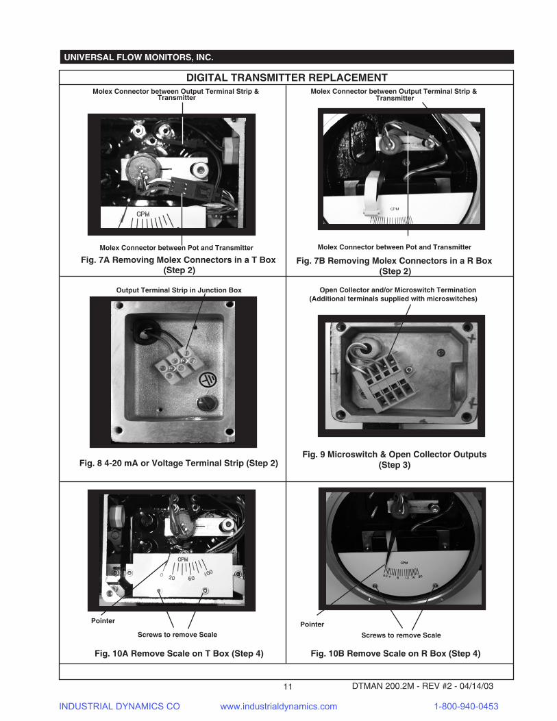
DIGITAL TRANSMITTER REPLACEMENT PROCEDURE
Universal Flow Monitors' new Digital Transmitter is designed to be user friendly. Checking, recalibrating orreplacement of a failed transmitter can be easily accomplished in the field. Each Flow Meter is suppliedwith its own Calibration Sheet (sample shown on page 14 & 15). Specific flow data such as mv signal, andrelated % of full scales calibration points are provided on this sheet. This procedure can be done in the fieldor at the bench level. Follow the instructions below for the applicable Control Box & Readout Options.
Control Box & Readout Options TTL, TTLZ,Remote Mounted Transmitter UT-PM-DTLCD &
Remote Programmer RPM-R*
ADJUSTA1
ENT./SETA2
ALARM 1
ALARM 2
23.0
Control Box & Readout OptionsTT, TTV, TTZ, RT, RTV, RTZ, TP, RP, & Remote
Mounted Transmitter UT-PM-DT
GPM
410 20 30
4050
0
50
3010
0
GPM
ROUND BOX
T BOX
Units with the LCD option require no special tools or instruments.
1. Shut off power to any switch in the control box, as well as isolate the loop if the process is running.2. Remove the nameplate and cover assembly from the control box, disconnect the 3 Molex connectors
between the Pot (3 wires) and the transmitter and the output terminal strip (2 wires going to terminationsin the junction box) (Figs. 7A, 7B & 8, pg. 11).
3. Disconnect the Open Collector Outputs (3 wires going to terminating junction box) (Fig. 9, pg. 11)4. Remove the scale using a 7/64 Allen wrench. Be careful not to bend the pointer when removing scale
(Figs. 10A & 10B, pg. 11). If pointer is bent or moved during scale removal, reposition pointer whenreinstalling scale. If the unit has a LCD, then there will be no scale to remove, go to step 5.
5. Remove the existing transmitter using a 9/64 Allen wrench (Figs. 11A & 11B, pg. 11).6. Install the replacement Transmitter.7. Reconnect the Pot connector and the Open Collectors.8. Refer to Step 1 of the Calibration Procedure before reconnecting the LCD loop power to enter the
calibration mode.9. You are now in calibration mode and begin entering data from the Original Calibration Sheet for this
meter, per the Steps 2-8 of the Calibration Procedures.
If you have Control Box & Readout options TT, TTV, RT, RTV, TTZ & RTZ you will require a RPM-R* Calibra-tor which includes a special ribbon cable, pin connector and a 9-volt battery with a Molex connector to supplypower to the Digital Transmitter to permit calibration at the bench, instead of using the loop power. Using thispower source and special connector, either unit, LCD or others, may be calibrated at the bench or in the field,without using the loop power source. Control Box & Readout options TTZ & RTZ must be bench calibrated.Simply reattach the Molex connector of the loop power source when the calibration is complete or when thebench calibrated transmitter is installed into the meter. The Blind Digital Transmitter has a mating specialribbon cable that allows connection of the RPM-R*, since it does not have an LCD display on which thecalibration data can be viewed, changed or entered (See Figs. 12A & 12B, pg.13). It also does not have theOpen Collector alarm function, as it is a function of the LCD board.
If the Digital Transmitter is a LCD version, refer to the section on Setting the Open Collector Alarms on page8-9, to enter the low, low low, high or high high set points desired for this application.*Note: Open Collector outputs are normally open for low and high alarm functions. So when using the low asa second high contact, or the high as a second low contact, they will be normally closed in this format,providing one NO and one NC contact.
*Indicates the current revision level of the Remote Calibrator.
INDUSTRIAL DYNAMICS CO www.industrialdynamics.com 1-800-940-0453
UNIVERSAL FLOW MONITORS, INC.
DTMAN 200.2M - REV #2 - 04/14/0311
Molex Connector between Pot and Transmitter
Molex Connector between Output Terminal Strip &Transmitter
DIGITAL TRANSMITTER REPLACEMENT
Fig. 7A Removing Molex Connectors in a T Box(Step 2)
Fig. 8 4-20 mA or Voltage Terminal Strip (Step 2)
Fig. 10A Remove Scale on T Box (Step 4)
Output Terminal Strip in Junction Box
Screws to remove Scale
Pointer
Screws to remove Scale
Pointer
Fig. 10B Remove Scale on R Box (Step 4)
Open Collector and/or Microswitch Termination
Fig. 9 Microswitch & Open Collector Outputs(Step 3)
(Additional terminals supplied with microswitches)
Fig. 7B Removing Molex Connectors in a R Box(Step 2)
Molex Connector between Pot and Transmitter
Molex Connector between Output Terminal Strip &Transmitter
INDUSTRIAL DYNAMICS CO www.industrialdynamics.com 1-800-940-0453
UNIVERSAL FLOW MONITORS, INC.
DTMAN 200.2M - REV #2 - 04/14/03 12
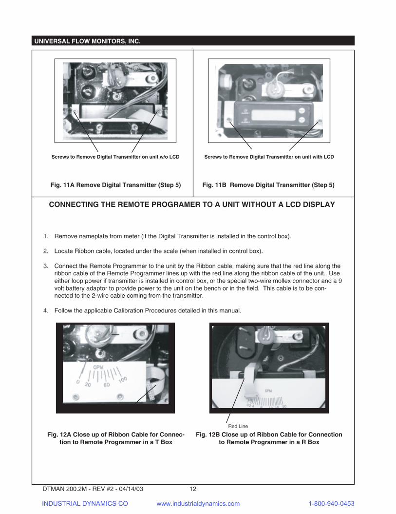
CONNECTING THE REMOTE PROGRAMER TO A UNIT WITHOUT A LCD DISPLAY
1. Remove nameplate from meter (if the Digital Transmitter is installed in the control box).
2. Locate Ribbon cable, located under the scale (when installed in control box).
3. Connect the Remote Programmer to the unit by the Ribbon cable, making sure that the red line along theribbon cable of the Remote Programmer lines up with the red line along the ribbon cable of the unit. Useeither loop power if transmitter is installed in control box, or the special two-wire mollex connector and a 9volt battery adaptor to provide power to the unit on the bench or in the field. This cable is to be con-nected to the 2-wire cable coming from the transmitter.
4. Follow the applicable Calibration Procedures detailed in this manual.
Fig. 12B Close up of Ribbon Cable for Connectionto Remote Programmer in a R Box
Fig. 12A Close up of Ribbon Cable for Connec-tion to Remote Programmer in a T Box
Red Line
Red Line
Fig. 11A Remove Digital Transmitter (Step 5)
Screws to Remove Digital Transmitter on unit w/o LCD Screws to Remove Digital Transmitter on unit with LCD
Fig. 11B Remove Digital Transmitter (Step 5)
INDUSTRIAL DYNAMICS CO www.industrialdynamics.com 1-800-940-0453

UNIVERSAL FLOW MONITORS, INC.
DTMAN 200.2M - REV #2 - 04/14/0313
CALIBRATION PROCEDURECalibration is performed by entering Manual CAL mode upon power-up. To perform this, an LCD display must be connected to the digital transmitter, either internally on a display meter or externally using a remote programming module (RPM-R*). The push buttons have multiple functions in CAL mode: the ADJUST button is used to either 1. "Skip" a parameter, 2. Adjust the digits for calibrating a set point, or 3. Switch between operating modes for the flow meter (forward or reverse flow). The ENT/SET button is used to enter the desired parameter into the EEPROM.1. To enter CAL mode press the ADJUST and ENT/SET buttons within 4 seconds of applying power to the meter �
(12-30VDC supply).2. Continue pressing both buttons during transmitter power up sequence. The transmitter will initially turn on all LCD
segments for 2 seconds. It will then display the Code revision for 2 seconds, followed by displaying "CAL", indicating that the transmitter is now in calibration mode. Release the ENT/SET button first and then release the ADJUST button.
3. The transmitter will display “For”; indicating that forward flow mode is selected. For reverse flow mode the transmitter will display “rE”. To switch between forward and reverse flow modes, press and release the ADJUST button. Once the desired mode of operation is selected, press and release the ENT/SET button.NOTE 1: “For” is the default setting. Every time you enter CAL mode the transmitter will automatically be set for forward flow. If “rE” mode is desired it must be manually selected each time CAL mode is entered.
4. The transmitter will display “P-0”, indicating that it is ready for the first percentage point (always 0%) to be calibrated. Press and release the ENT/SET button.NOTE 2: To “skip” a calibration point (previously calibrated transmitter only), press and release the ADJUST button to cycle to the next percentage point (P-1, P-2, etc.).
5. The transmitter will display a four-digit value with the first digit blinking. To adjust this digit, press the ADJUST button to cycle from 0-9 and back to 0. To enter the value and cycle to the next digit press and release the ENT/SET button.
5.1.Repeat step 5 for the subsequent digits. After the most significant digit is entered, hold down the ENT/SET button until “SEt” is displayed and then release the button. NOTE 3: If you need to go back and change any of the digits, press and release the ENT/SET button after the most significant digit is adjusted. The calibration will cycle back to the least significant digit
6. The transmitter will display “U-0” for 1.5 seconds, followed by a four digit value indicating that it is ready for the voltage corresponding to the first percentage point (0%) to be calibrated. Input the voltage value, following steps 4 and 4.1 above for adjusting the display.
7. The transmitter will display “P-1”, indicating that it is ready for the second percentage point to be calibrated. There are a total of 9 percentage points (including 0%) numbered P-0 through P-8, and 9 corresponding voltages numbered U-0 through U-8 to be calibrated on the digital transmitter. Repeat steps 5 through 6 for each of these calibrations points up to and including P-8/U-8 (100% point).NOTE 4: The percentage points and the corresponding voltages are listed on the Calibration Sheet for the Meter.NOTE 5: There are two aids in determining whether the transmitter is displaying percentage or voltage. The first aid is the high and low alarm LED’s. The high alarm LED is on during percentage point calibration. The low alarm LED is on during voltage calibration. The second aid is the decimal point location. The display is to one decimal place during the percentage calibration. The display is to three decimal places during the voltage calibration.
8. When the ENT/SET button is pushed at the end of the P-8/U-8 calibration the transmitter will display “SEt” for 1 second, followed by “FS” for 1 second. The transmitter will then display a 4-digit value, indicating that it is in full-scale display calibration mode.NOTE 6: The first time that a transmitter is calibrated it is undetermined what 4 digit Value will be displayed and, in fact, it is possible that more than one decimal point will be initially activated. This is normal for a transmitter that has not been previously calibrated.
8.1.Set the decimal place for the display by pressing and holding the ADJUST button. The display will cycle between 0, 1 and 2 decimal places. When the decimal point is in the desired position, release the ADJUST button. Press and release the ENT/SET button.
8.2.The digits for the full-scale display value are calibrated following the instructions in steps 5 and 5.1. After the most significant digit is entered, press and hold the ENT/SET button. The transmitter will display “SEt” for 1 second, indicating that it has exited to run mode. Release the ENT/SET button. The flow meter should now function properly under flow.NOTE 7: If it is necessary to re-check or change any calibration points, it will be necessary to re-enter the Calibration Mode.This calibration procedure requires the use of all available calibration points. If it is desired that fewer points be calibrated, the following must be done: All used calibration points must be in consecutive order starting with P-0 (0%) and ending with the 100% calibration point.NOTE: ALL unused calibration points must be set to a valid value and the points entered into the Transmitter by pressing and releasing the ENT/SET button. For a 4-calibration point transmitter P2, P4, P6 & P8 will be duplicate numbers for the numbers entered into P1, P3, P5 & P7 and must be entered into the transmitter. For a 5-calibration point transmitter P4, P6 & P8 will be duplicate numbers for the numbers entered into P3, P5 & P7 and must be entered into the transmitter. For a 6-calibration point transmitter P6 & P8 will be duplicate numbers for the numbers entered into P5 & P7 and must be entered into the transmitter. For a 7-calibration point transmitter P8 will be a duplicate number for the number entered into P7 and must be entered into the transmitter. Failure to comply with these instructions will result in transmitter malfunction.
INDUSTRIAL DYNAMICS CO www.industrialdynamics.com 1-800-940-0453

UNIVERSAL FLOW MONITORS, INC.
DTMAN 200.2M - REV #2 - 04/14/03 14
UNIVERSAL FLOW MONITORS, INC.1755 East Nine Mile RoadP.O. Box 249, Hazel Park MI 48030-0249(248) 542-9635 • Fax (248) 398-4274
O------------------------------------------------------------------------------------------------------------------ --------------; Transmitter S/N: 010300757 Model: SN-ASB2GM-6-789V.9-TT1WU-.6D; Full-scale display: 30.0 GPM Asset: 0001; Calibration points: 6; Flow direction: Forward; Hysteresis band (%): +/- 2 ; High Alarm: 6.0; Low Alarm: 24.0; Pot Zero (volts): 0.030; Pot Offset (mV): 8;--------------------------------------------------------------------------; Comments:; This is a Test file with Comments typed in DTCom3.1 program.; The Second line is here. Press 'C' to Clear the text.; Use the 'Tab' key to switch between text lines;--------------------------------------------------------------------------V-Up V-Down V-Split Hyst Percent mA Flow(GPM)0.266 0.274 0.270 1.5 100.00 20.00 300.266 0.274 0.270 1.5 100.00 20.00 300.220 0.230 0.225 1.9 80.00 16.80 240.220 0.230 0.225 1.9 80.00 16.80 240.176 0.186 0.181 1.9 60.00 13.60 180.132 0.142 0.137 1.9 40.00 10.40 120.086 0.094 0.090 1.5 20.00 7.20 60.049 0.059 0.054 1.9 10.00 5.60 30.038 0.038 0.038 0.0 00.00 4.00 0
;---------------------------------------------------------------------------; FOR UFM USE ONLY ;---------------------------------------------------------------------------; [ ]Master mA LCD LCD mA mA ; [ ]Scale Out Up Down Up Down ;---------------------------------------------------------------------------; ;---------------------------------------------------------------------------; ;---------------------------------------------------------------------------; ;---------------------------------------------------------------------------; ;---------------------------------------------------------------------------; ;---------------------------------------------------------------------------; ;---------------------------------------------------------------------------; ;---------------------------------------------------------------------------; ;---------------------------------------------------------------------------; ;---------------------------------------------------------------------------; ;------------------------------ DTCOM3.1 ----------------------------
SAMPLE
INDUSTRIAL DYNAMICS CO www.industrialdynamics.com 1-800-940-0453

UNIVERSAL FLOW MONITORS, INC.
DTMAN 200.2M - REV #2 - 04/14/0315
DIGITAL TRANSMITTER CALIBRATION SHEET INSTRUCTIONS
PURPOSE: This is to enable the Calibration Technician in filing out the Transmitter Calibration Sheet correctly and enable the customer to understand what the data that is recorded means.
SCOPE: This applies to all UFM Calibration Technicians and customers who need to understand the data recorded.
1. Transmitter S/N: This is for recording the serial number of the transmitter being calibrated.2. Model: This is for recording the model number of the meter that is being calibrated.3. Full-scale display: This is where the maximum calibrated flow point is recorded.4. Asset: This is where the number that is written on the solder side of the Digital Transmitter circuit
board is recorded.5. Calibration points: This is where the number of calibration points that the transmitter has been
calibrated for is recorded.6. Flow direction: This is where the flow direction of the meter is recorded.7. Hysteresis Band (%): This is where the Total allowable Hysteresis of the meter is recorded.8. High Alarm: This is where the High Alarm Set Point is recorded which is only valid for those
transmitters that have an LCD display.9. Low Alarm: This is where the Low Alarm Set Point is recorded which is only valid for those
transmitters that have an LCD display.10.Pot Zero (volts): This is where the split voltage for 0% of flow is recorded before Pot Offset voltage is
added for the deadband.11.Pot Offset (mV): This is where the actual Pot Offset voltage is recorded.12.Comments: This section is used for making any notes that the technician may feel is important for
reference that may be helpful at a future date.13.V-Up: This is where the actual voltage for the flow point when going from zero to the maximum flow is
recorded.14.V-Down: This is where the actual voltage for the flow point when going from the maximum flow to
zero flow is recorded.15.V-Split: This is where the split voltage, which was calculated from the V-Up and V-Down voltages is
recorded.16.Hyst: This is where the actual hysteresis of each flow point is recorded.17.Percent: This is where the percentage of flow is recorded. This is calculated by dividing the flow rate
at the point by the Max. Flow Rate. Example: The flow rate at this Calibration point is 2 GPM and the Max. Flow Rate is 10 GPM. 2 divided by 10 is .2 or 20%.
18.mA: This is where the output current that represents the flow rate for the 4-20mA output is recorded. The number is determined by multiplying 16.00 mA (which is the amount of current between 0 and the maximum calibrated current point) by the percentage of flow for that calibration point. Then 4.00 mA is added to the results. Example: The 2 GPM point on a 10 GPM meter is .2 (20%) times 16.00 plus 4.00 which is 7.20mA.
19.Flow (XXX): This is where the flow units of measurement are recorded and the type of measurement is recorded. Example: If the flow is measured in gallons per minute the GPM would be recorded and all the numbers in this column would reflect the GPM readings. P0 would be the 0 GPM flow point and P8 would be the Maximum calibrated flow point.
20.FOR UFM USE ONLY: This is where the actual flow rate is recorded with respect to the displayed flow rate. For those models that have a LCD Display, the actual flow rate on the calibration stand will be indicated for both up and down flow. For those units with a scale the current for that scale mark will be recorded.
INDUSTRIAL DYNAMICS CO www.industrialdynamics.com 1-800-940-0453