unit-3 & 4 embedded systems (a1430) rtos.pdf
TRANSCRIPT
J. KRISHNA CHAITHANYA Associate Professor
EMBEDDED SYSTEMS (A1430) UNIT-III & IV RTOS
Department of Electronics and Communication Engineering
(AUTONOMOUS) Shamshabad, Hyderabad - 501218

3.0 INTRODUCTION TO REAL-TIME OPERATING SYSTEMS (RTOS)
A more complex software architecture is needed to handle multiple tasks, coordination, communication, and interrupt handling – an RTOS architecture
Distinction:
Desktop OS – OS is in control at all times and runs applications, OS runs in different address space
RTOS – OS and embedded software are integrated, ES starts and activates the OS – both run in the same address space (RTOS is less protected)
RTOS includes only service routines needed by the ES application
RTOS vendors: VxWorks (we got it!), VTRX, Nucleus, LynxOS, uC/OS
Most conform to POSIX (IEEE standard for OS interfaces)
Desirable RTOS properties: use less memory, application programming interface, debugging tools, support for variety of microprocessors, already-debugged network drivers

3.1 Tasks and Task States
A task – a simple subroutine
ES application makes calls to the RTOS functions to start tasks, passing to the OS, start address, stack pointers, etc. of the tasks
Task States:
Running
Ready (possibly: suspended, pended)
Blocked (possibly: waiting, dormant, delayed)
[Exit]
Scheduler – schedules/shuffles tasks between Running and Ready states
Blocking is self-blocking by tasks, and moved to Running state via other tasks’ interrupt signaling (when block-factor is removed/satisfied)
When a task is unblocked with a higher priority over the ‘running’ task, the scheduler ‘switches’ context immediately (for all pre-emptive RTOSs)
(See Fig 6.1)


3.1 Tasks – 1
Issue – Scheduler/Task signal exchange for block-unblock of tasks via function calls
Issue – All tasks are blocked and scheduler idles forever (not desirable!)
Issue – Two or more tasks with same priority levels in Ready state (time-slice, FIFO)
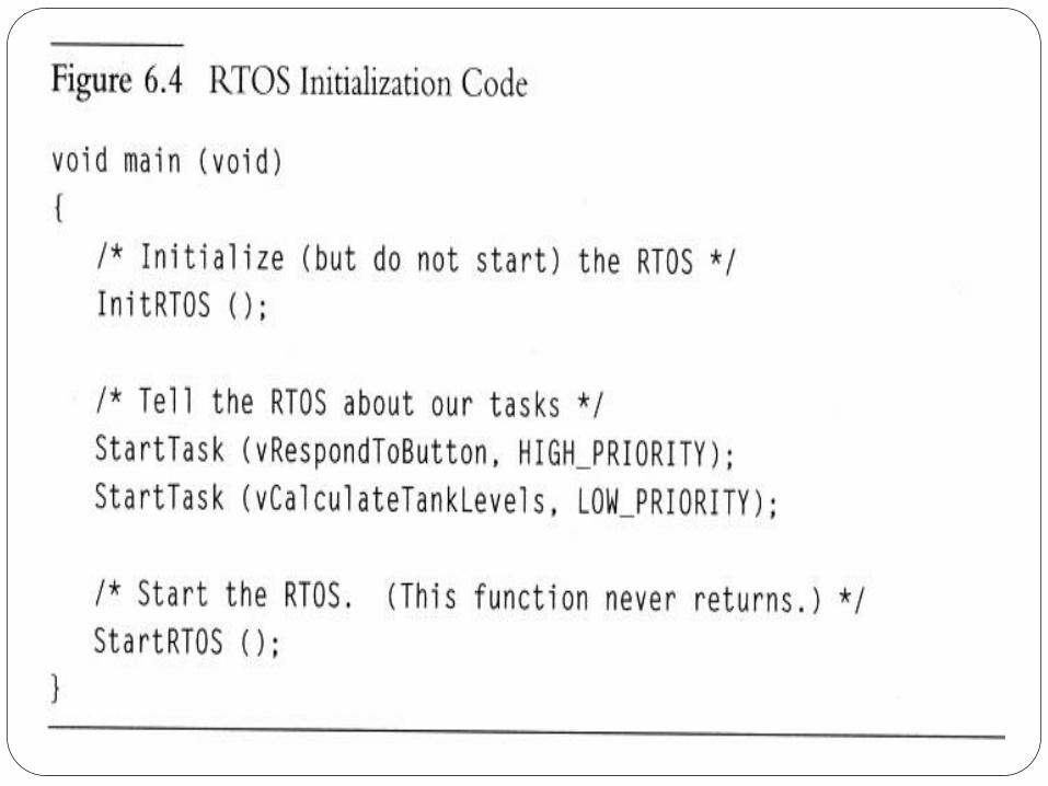
Example: scheduler switches from processor-hog vLevelsTask to vButtonTask (on user interruption by pressing a push-button), controlled by the main() which initializes the RTOS, sets priority levels, and starts the RTOS
(See Fig 6.2, Fig 6.3, Fig 6.4)


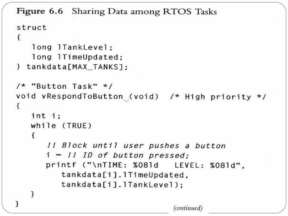
3.3 Tasks and Data
Each tasks has its won context - not shared, private registers, stack, etc.
In addition, several tasks share common data (via global data declaration; use of ‘extern’ in one task to point to another task that declares the shared data
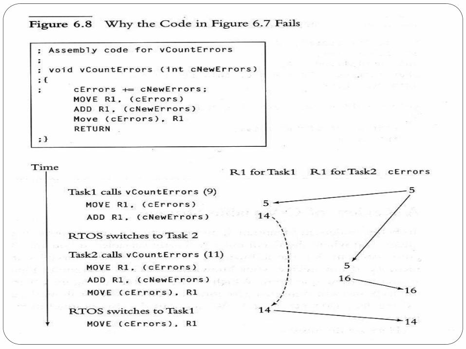
Shared data caused the ‘shared-data problem’ without solutions discussed in Chp4 or use of ‘Reentrancy’ characterization of functions
(See Fig 6.5, Fig 6.6, Fig 6.7, and Fig 6.8)


3.2 Tasks – 2
Reentrancy – A function that works correctly regardless of the number of tasks that call it between interrupts
Characteristics of reentrant functions –
Only access shared variable in an atomic-way, or when variable is on callee’s stack
A reentrant function calls only reentrant functions
A reentrant function uses system hardware (shared resource) atomically
Inspecting code to determine Reentrancy:
See Fig 6.9 – Where are data stored in C? Shared, non-shared, or stacked?
See Fig 6.10 – Is it reentrant? What about variable fError? Is printf reentrant?
If shared variables are not protected, could they be accessed using single assembly instructions (guaranteeing non-atomicity)?


20
Race condition Assume the scenario in which
process A reads the free slot (e.g. 7) but before printing, CPU switches to process B and process B reads the free slot ( again 7 ) and prints its file name there and updates it to 8. In that case when CPU switches back to process A , it starts from the point it left off and writes its file in 7. Thus process B never gets the print of its file.
Situations like this , when two processes are using the shared data and result depends on who runs precisely when are called race conditions.

21
Race condition
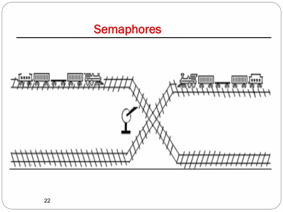
Semaphore is one of the ways for providing mutual exclusion by protecting critical regions.
22
Semaphores
23
Semaphore Definition
A semaphore is a data structure that is shared by several processes. Semaphores are most often used to synchronize operations (to avoid race conditions) when multiple processes access a common, non-shareable resource.
By using semaphores, we attempt to avoid other multi-programming problems such as:
Starvation » Occurs when a process is habitually denied access
to a resource it needs.
Deadlock » Occurs when two or more processes each hold a
resource that the other needs while waiting for the other process to release its resource.

24
Semaphore Definition
To indicate a process has gained access to the resource, the process decrements the semaphore.
For events to progress correctly, the test and decrement operation on the semaphore must be atomic (i.e., no interruptible/indivisible).
There are two kinds of Semaphores:
Binary semaphores
» Control access to a single resource, taking the value of 0 (resource is in use) or 1 (resource is available).
Counting semaphores
» Control access to multiple resources, thus assuming a range of nonnegative values.
25
Semaphore Definition
Semaphore is a nonnegative integer that is stored in the kernel.
Access to the semaphore is provided by a series of semaphore system calls.
26
Creating and Accessing Semaphore Sets
Before a semaphore set can be used, it must be created.
The creation of the semaphore set generates a unique data structure that the system uses to identify and manipulate the semaphores.
A conceptual arrangement of a system semaphore structure for a newly allocated set of three semaphores is shown in Figure 1.

27
Creating and Accessing Semaphore Sets
Figure 1. Data structures for a set of three semaphores.
28
Creating and Accessing Semaphore Sets
To create a semaphore or gain access to one that exists, the semget system call is used.
(Table 1)

29
Creating and Accessing Semaphore Sets
Return
int semget (key_t key,intnsems,int semflg); Summary
2 Manual Section
<sys/types.h>
<sys/ipc.h>
<sys/sem.h>
Include File(s)
Sets errno Failure Success
Yes -1 The semaphore identifier
Table 1. Summary of the semget System Call

3.3 Semaphores and Shared Data – A new tool for atomicity
Semaphore – a variable/lock/flag used to control access to shared resource (to avoid shared-data problems in RTOS)
Protection at the start is via primitive function, called take, indexed by the semaphore
Protection at the end is via a primitive function, called release, also indexed similarly
Simple semaphores – Binary semaphores are often adequate for shared data problems in RTOS
(See Fig 6.12 and Fig 6.13)


3.3 Semaphores and Shared Data – 1
RTOS Semaphores & Initializing Semaphores
Using binary semaphores to solve the ‘tank monitoring’ problem
(See Fig 6.12 and Fig 6.13)
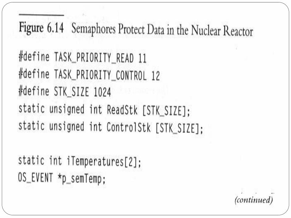
The nuclear reactor system: The issue of initializing the semaphore variable in a dedicated task (not in a ‘competing’ task) before initializing the OS – timing of tasks and priority overrides, which can undermine the effect of the semaphores
Solution: Call OSSemInit() before OSInit()
(See Fig 6.14)


3.3 Semaphores and Shared Data – 2
Reentrancy, Semaphores, Multiple Semaphores, Device Signaling,
Fig 6.15 – a reentrant function, protecting a shared data, cErrors, in critical section
Each shared data (resource/device) requires a separate semaphore for individual protection, allowing multiple tasks and data/resources/devices to be shared exclusively, while allowing efficient implementation and response time
Fig 6.16 – example of a printer device signaled by a report-buffering task, via semaphore signaling, on each print of lines constituting the formatted and buffered report


3.3 Semaphores and Shared Data – 3
Semaphore Problems – ‘Messing up’ with semaphores
The initial values of semaphores – when not set properly or at the wrong place
The ‘symmetry’ of takes and releases – must match or correspond – each ‘take’ must have a corresponding ‘release’ somewhere in the ES application
‘Taking’ the wrong semaphore unintentionally (issue with multiple semaphores)
Holding a semaphore for too long can cause ‘waiting’ tasks’ deadline to be missed
Priorities could be ‘inverted’ and usually solved by ‘priority inheritance/promotion’
(See Fig 6.17)
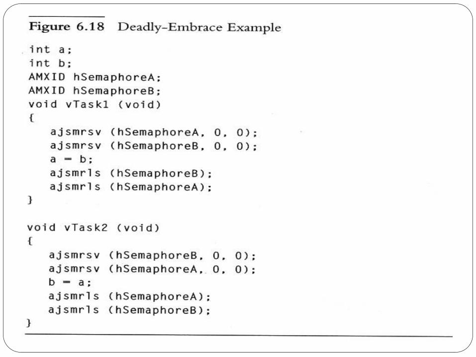
Causing the deadly embrace problem (cycles)
(See Fig 6.18)


3.3 Semaphores and Shared Data – 4
Variants:
Binary semaphores – single resource, one-at-a time, alternating in use (also for resources)
Counting semaphores – multiple instances of resources, increase/decrease of integer semaphore variable
Mutex – protects data shared while dealing with priority inversion problem
Summary – Protecting shared data in RTOS
Disabling/Enabling interrupts (for task code and interrupt routines), faster
Taking/Releasing semaphores (can’t use them in interrupt routines), slower, affecting response times of those tasks that need the semaphore
Disabling task switches (no effect on interrupt routines), holds all other tasks’ response

More Operating System Services
The other features offered by commercial RTOSs.

Contents Message Queues, Mailboxes and Pipes
Timer Functions
Events
Memory Management
Interrupt Routines in an RTOS Environment

Message Queues, Mailboxes and Pipes
Task must be able to communicate with one another to coordinate their activities or to share data.
queues, mailboxes, and pipes

Message Queues, Mailboxes and Pipes
void Task1(void)
{
…
if (!!problem arises)
vLogError(ERROR_TYPE_X);
…
!! Other things that need to be done soon.
}
void Task2(void)
{
…
if (!!problem arises)
vLogError(ERROR_TYPE_Y);
…
!! Other things that need to be done soon.
}
void vLogError(int iErrorType)
{
AddToQueue(iErrorType);
}
static int cErrors;
void ErrorTask(void)
{
int iErrorType;
while(FOREVER)
{
ReadFromQueue(&iErrorType);
++cErrors;
!! Send cErrors and iErrorType out on network
}
}

Details with Message Queues Initialize your queues before using queue.
Have as many queues as you want
the identity of the queue
When queue is full, the RTOS must
return an error
block
Details with Message Queues A function that will read from a queue if there is any data
and will return error code and block if not.
Write onto a queue the number of bytes taken up by a void pointer

Pointer and Queues Casting the data as a void pointer
One task can pass data to one other task
Put the data into buffer
And write a pointer to the buffer onto queue
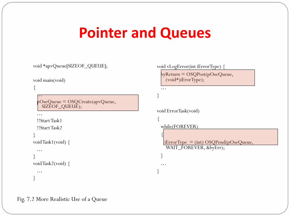
Pointer and Queues
void *apvQueue[SIZEOF_QUEUE];
void main(void)
{
…
pOseQueue = OSQCreate(apvQueue, SIZEOF_QUEUE);
…
!!Start Task1
!!Start Task2
}
void Task1(void) {
…
}
void Task2(void) {
…
}
void vLogError(int iErrorType) {
byReturn = OSQPost(pOseQueue, (void*)iErorType);
…
}
void ErrorTask(void)
{
while(FOREVER)
{
iErrorType = (int) OSQPend(pOseQueue, WAIT_FOREVER, &byErr);
}
…
}
Fig. 7.2 More Realistic Use of a Queue

static OS_EVENT *pOseQueueTemp;
void vReadTemperaturesTask(void)
{
int *pTemperatures;
While(TRUE) {
…
pTemperatures = (int*)malloc(2*sizeof*pTemperatures);
pTemperatures[0] =
pTemperatures[1] =
OSQPost(pOseQueueTemp,
(void*)pTemperatures);
}
}
void vMainTask(void)
{
int *pTemperatures;
BYTE byErr;
while(TRUE)
{
pTemperatures = (int*)OSQPend(pOseQueueTemp, WAIT_FOREVER, &byErr);
if (pTemperatures[0] != pTemperatures[1])
!! Set Off howling alarm;
}
}
Fig. 7.3 Passing Pointer on Queues
Pointer and Queues

Mailboxes Much like queues.
RTOS can Create, write ,check and read from mail boxes.
The number of messages in a mailbox is limited.
User can prioritize mailbox messages.
MultiTask! sndmsg, rcvmsg, chkmsg

Pipes Much like queues.
RTOS can
Create, write ,check and read from pipes.
Byte-oriented.
Use fread(), fwrite()
Which should we use? Trade-offs among
Flexibility, speed, memory space, disabled interrupt time length
Refer to documents

Pitfalls
void vReadTemperaturesTask(void)
{
int *pTemperatures;
While(TRUE) {
…
pTemperatures = (int*)malloc(2*sizeof*pTemperatures);
pTemperatures[0] =
pTemperatures[1] =
OSQPost(pOseQueueTemp,
(void*)pTemperatures);
}
}
void vReadTemperaturesTask(void)
{
int iTemperatures[2];
While(TRUE) {
…
iTemperatures[0] =
iTemperatures[1] =
OSQPost(pOseQueueTemp,
(void*)iTemperatures);
}
}
•Passing Pointers through a queue may create
shared data bugs

Timer Functions Must Keep track of the passage of time
Offer taskDelay() functions.
void vMakePhoneCallTask(void)
{
…
taskDelay(100);
vDialingToneOn(*p_chPhoneNumber –’0’);
taskDelay(100);
vDialingToneOff();
…
}

Events • Procedure
1. More than task can block waiting
2. The events occurs
3. The RTOS will unblock all of tasks
Form group of events and any subset of events within the group
Need to reset events automatically or manually

Comparison for Inter task Comm.
Semaphore : the fastest and simplest
not much information
Events : more complicated than semapohre
can wait several events at the same time
take more CPU time
Queues : much information
CPU-intensive
bugs-opportunity.

Memory Management Avoid malloc and free function
Slow and unpredictable
Use the functions that allocate and free fixed-size buffers. Predictable
At MultiTask! system void *getbuf(PoolID, timeout); void *reqbuf(PoolID); void *reluf(PoolID, *p_vBuffer);
NOTE-: The function malloc is used to allocate a certain amount of memory during the execution of a program. The malloc function will request a block of memory from the heap. If the request is granted, the operating system will reserve the requested amount of memory. When the amount of memory is not needed anymore, you must return it to the operating system by calling the function free.
To allocate space for an array in memory you use calloc()
To allocate a memory block you use malloc()
To reallocate a memory block with specific size you use realloc()
To de-allocate previously allocated memory you use free()

Interrupt Routines in an RTOS Environment
Interrupt Routines must not call any RTOS functions that-
1. Might block the caller.
2. Might cause the RTOS to switching tasks without fair
warning

Interrupt Routines in an RTOS Environment
RTOS
TaskLow
ISR
TaskHigh Send message
to mailbox
Time
Fig. 7.14 How Interrupt Routines Should Work
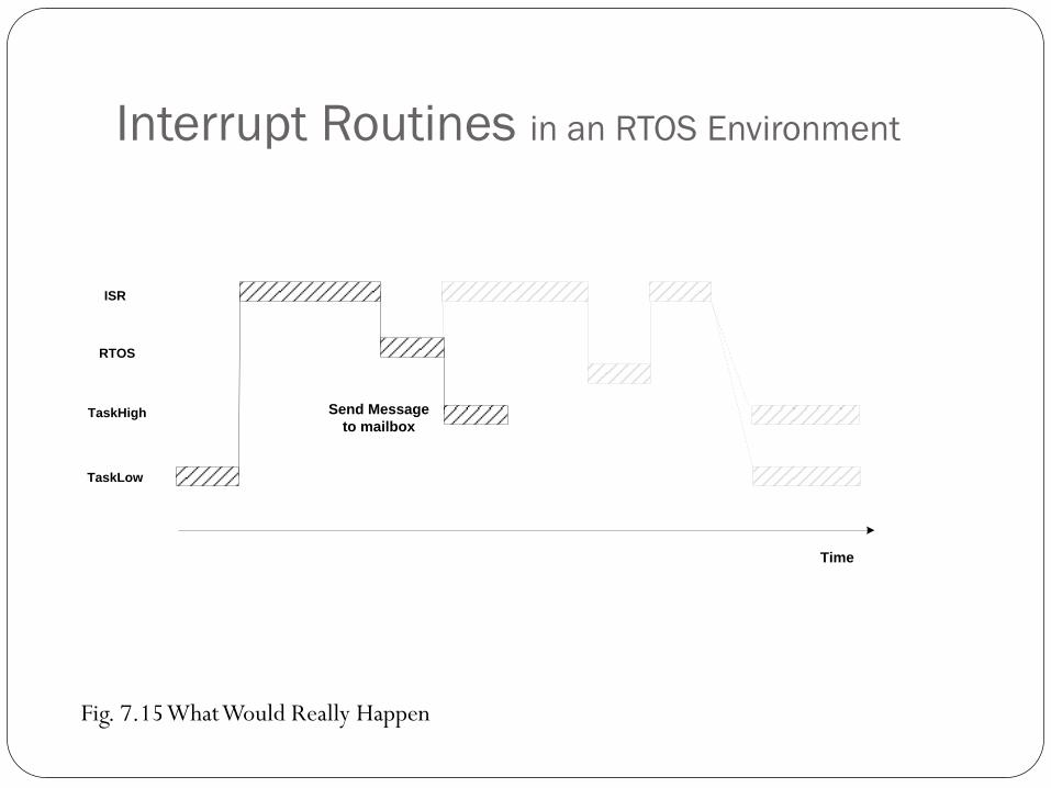
Interrupt Routines in an RTOS Environment
RTOS
TaskLow
ISR
TaskHigh Send Message
to mailbox
Time
Fig. 7.15 What Would Really Happen

Interrupt Routines in an RTOS Environment
Fig. 7.16 How Interrupt Routines Do Work
1. The RTOS intercepts all the interrupts and then call your interrupt routine.
RTOS
TaskLow
ISR
TaskHigh
Call
Send Message
to mailbox
Return
Time

Interrupt Routines in an RTOS Environment
Fig. 7.17 How Interrupt Routines Do Work:Plan B
2. Disabling the scheduler for the duration of the interrupt routine.
RTOS
TaskLow
ISR
TaskHigh
Time
Enter
interrupt
routine.
Send Message
to mailbox
Jump or call

Interrupt Routines in an RTOS Environment
3. A separate set of functions for
interrupt routines specially
OSSemPost
OSISRSemPost for interrupt routines

Nested Interrupts
RTOS
TaskLow
TaskHigh
Time
Low-priority
ISR
High-priority
ISR
High-priority
interrupt
occurs.
Send Message
to mailbox
RTOS schedler goes to TaskHigh
instead of finishing low-priority ISR.
• The RTOS must know
when the lower-priority interrupt routine.
Fig. 7.18 Nested Interrupts and the RTOS

BASIC DESIGN OF AN EMBEDDED SOFTWARE USING RTOS
To design an ES, first pick a software architecture –
Round Robin
Round Robin with Interrupts
Function-Queue-Scheduling
RTOS
ES design concept and techniques discussed in assumes the RTOS architecture
Key RTOS mechanisms used include tasks, task management, inter task communication mechanisms (semaphores, queues, mailboxes, pipes), and interrupts

BASIC DESIGN OF AN EMBEDDED SOFTWARE USING RTOS
Prior to design, we must construct a specification of the ES to meet such requirements / properties as:
Completeness
Time (timing constraints - response time, reactive time, deadlines – soft vs. hard)
Properties of the target hardware (for effective design of the ES), e.g., a 9600-bps serial port that receives 1200 chars per second, requires an IR that handles interrupts 1200 times each second. If chars can be written to RAM using DMA, IR code will be different
Knowledge of microprocessor speed – can the mproc run the IR 1200 times per sec?
Need all the software engineering skill you have, plus such properties as: structures, encapsulation, info-hiding, modularity, coupling, cohesion, maintainability, testability
Effective use of design tools and methodologies – RoseRT, OO, UML, YES-UML, …
Testing and debugging ES requires specialized hardware tools and software tools and techniques

Design considerations
ES is interrupt-driven and ES remains dormant until
Time passes for an event to occur (timer interrupt)
A need for a response to an external request/interrupt arises
Interrupts create cascade of events, causing RTOS tasks act/behave accordingly
ES design technique: Create all needed tasks, get them into blocked-state or idle state – waiting on interrupts (to be generated by an external event, e.g., frame-arrival at a network port)
(See Fig 8.1 – network port and serial port comm via tasks that implement DDP and ADSP protocol stack)


Principles – 1
Write Short IR’s:
Even lowest priority IR’s are handled before the highest priority task code (minimize task code response time)
IR’s are error prone and hard to debug (due to hardware-dependent software parts)
Parts IR code requiring immediate / quick response should be in the core of IR code; parts needing ‘longer’ processing and not-so-urgent response should be done a task (signaled by the IR)

Principles – 2
Consider the ff specs:
A system responds to commands from a serial port
All commands end with a carriage-return (CR)
Commands arrive one at a time, the next arrives iff the preceding one is processed
Serial port’s buffer is 1 character long, and characters arrive quickly (at X bps)
System’s processing time per character is Y char per second
Three possible designs:
A. Let IR handle everything => long response time, big IR code, hard to debug errors
B. Let skeletal IR code, with a command parsing task that queues commands (with all the attendant message/data queuing problems
C. Better compromise: Let IR save chars in a mailbox-buffer until CR, then the command parsing task can work on the buffer
(See Fig 8.2 – IR and parsing-task use different parts of the mail-buffer: tail and head)


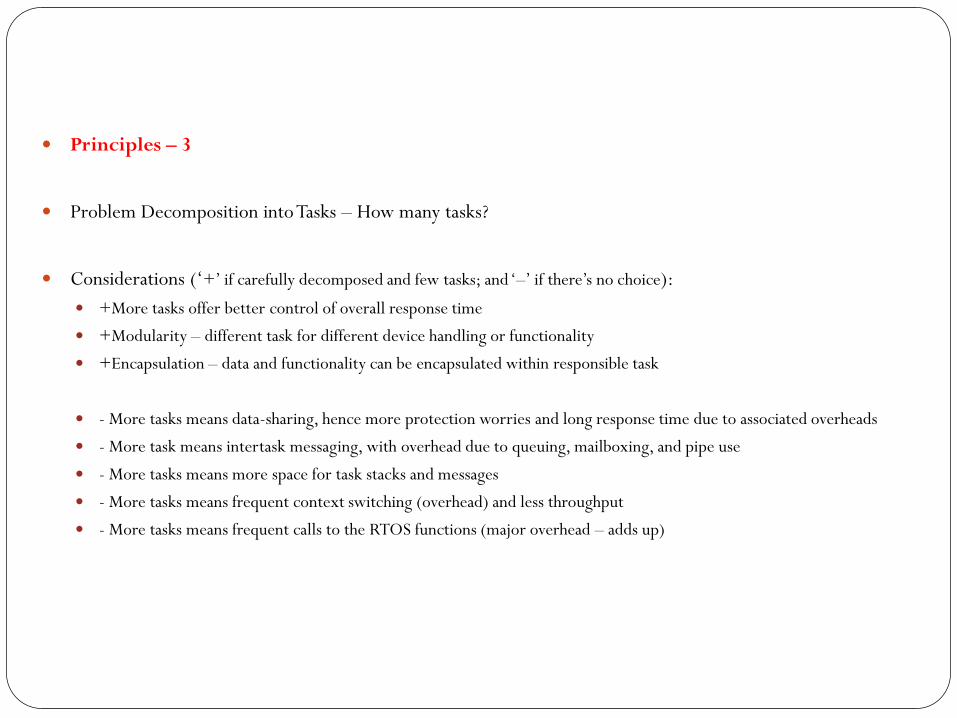
Principles – 3
Problem Decomposition into Tasks – How many tasks?
Considerations (‘+’ if carefully decomposed and few tasks; and ‘–’ if there’s no choice):
+More tasks offer better control of overall response time
+Modularity – different task for different device handling or functionality
+Encapsulation – data and functionality can be encapsulated within responsible task
- More tasks means data-sharing, hence more protection worries and long response time due to associated overheads
- More task means intertask messaging, with overhead due to queuing, mailboxing, and pipe use
- More tasks means more space for task stacks and messages
- More tasks means frequent context switching (overhead) and less throughput
- More tasks means frequent calls to the RTOS functions (major overhead – adds up)

Principles – 3
Priorities (advantage of using RTOS software architecture):
Decomposing based on ‘functionality’ and ‘time criticality,’ separates ES components into tasks (naturally), for
quicker response time using task prioritization – high priority for time-critical ones, and low priority for
others
Encapsulating functionality in Tasks
A dedicated task to encapsulate the handling of each shared device (e.g., printer display unit) or a common
data structure (e.g., an error log)
(See Fig 8.3)
Parts of a target hardware storing data in a flash memory – a single task encapsulates the handling of
permission-to-write-to-flash (set / reset of flash at given times)
(See Fig 8.4 – using POSIX standard RTOS functions: mq_open, mq_receive, mq_send, nanosleep)


Principles – 4
Other Tasks ?
Need many small, simple tasks? But worry about data-sharing, intertask comm …
Need a task per stimuli? Same problems!
Recommended Task Structure
Modeled/Structured as State-Machines –
Tasks run in an infinite loop
Tasks wait on RTOS for an event (expected in each task’s independent message queue)
Tasks declare their own private data to use (fully encapsulated)
Tasks block on in one place (RTOS signal), and not any other semaphore, no data sharing
Tasks use no microprocessor time when their queues are empty
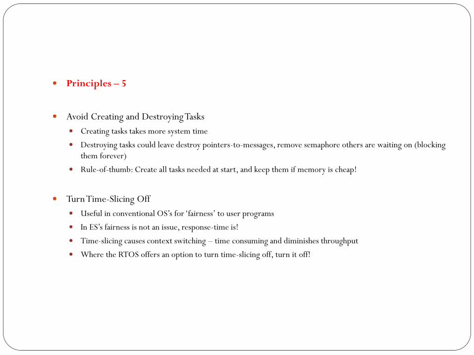
Principles – 5
Avoid Creating and Destroying Tasks
Creating tasks takes more system time
Destroying tasks could leave destroy pointers-to-messages, remove semaphore others are waiting on (blocking
them forever)
Rule-of-thumb: Create all tasks needed at start, and keep them if memory is cheap!
Turn Time-Slicing Off
Useful in conventional OS’s for ‘fairness’ to user programs
In ES’s fairness is not an issue, response-time is!
Time-slicing causes context switching – time consuming and diminishes throughput
Where the RTOS offers an option to turn time-slicing off, turn it off!

Principles – 6
Restrict the use of RTOS functions/features
Customize the RTOS features to your needs (Note: the RTOS and your ES gets linked and located together
into same address space of ROM/RAM – See Chapter 9)
If possible write ES functions to interface with RTOS select features to minimize excessive calls to several
RTOS functions (increases opportunity for errors)
Develop a shell around the RTOS functions, and let your own ES tasks call the shell (and not the RTOS
directly) – improves portability since only the shell may be rewritten fro RTOS to RTOS

An Example – Designing an Underground Tank Monitoring ES System
Summary of Problem Specification:
System of 8 underground tanks
Measures read:
temperature of gas (thermometer) read at any time
float levels (float hardware) interrupted periodically by the microprocessor
Calculate the number of gallons per tank using both measures
Set an alarm on leaking tank (when level slowly and consistently falls over time)
Set an alarm on overflow (level rising slowly close to full-level)
User interface: a) 16-button control panel, LCD, thermal printer
System can override user display options and show warning messages
Histories of levels and temperature over time can be requested by user (30-50 lines long) and user can queue up ‘several’ reports
Issuing commands require 2 or 3 buttons, and system can prompt the display in the middle of a user command sequence
Buttons interrupt the microprocessor
One dedicated button turns alarm off (connected to the system) through software
The printer prints one line at a time, and interrupts the microprocessor when done
The LCD prints the most recent line; saves its display-data and doesn’t need the microprocessor to retrieve info
(See Fig 8.7)

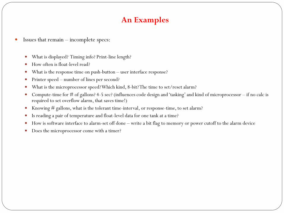
An Examples
Issues that remain – incomplete specs:
What is displayed? Timing info? Print-line length?
How often is float-level read?
What is the response time on push-button – user interface response?
Printer speed – number of lines per second?
What is the microprocessor speed? Which kind, 8-bit? The time to set/reset alarm?
Compute-time for # of gallons? 4-5 sec? (influences code design and ‘tasking’ and kind of microprocessor – if no calc is required to set overflow alarm, that saves time!)
Knowing # gallons, what is the tolerant time-interval, or response-time, to set alarm?
Is reading a pair of temperature and float-level data for one tank at a time?
How is software interface to alarm-set off done – write a bit flag to memory or power cutoff to the alarm device
Does the microprocessor come with a timer?
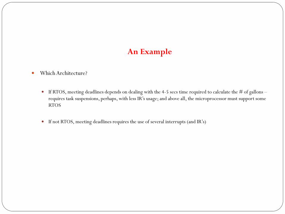
An Example
Which Architecture?
If RTOS, meeting deadlines depends on dealing with the 4-5 secs time required to calculate the # of gallons –
requires task suspensions, perhaps, with less IR’s usage; and above all, the microprocessor must support some
RTOS
If not RTOS, meeting deadlines requires the use of several interrupts (and IR’s)

An Example
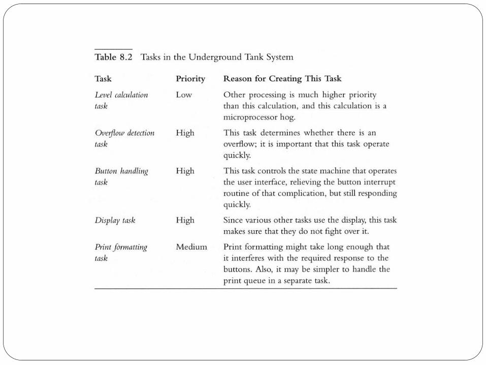
System Decomposition for Tasks
One low priority task that handles all # gallons calculations and detects leaks as well (for all tanks – 1 at a time)
A high priority overflow-detection task (higher than a leak-detection task)
A high priority float-hardware task, using semaphores to make the level-calc and overflow-detection task wait on it for reading (semaphores will be simpler, faster than queuing requests to read levels)
A high priority button handling tasks – need a state-machine model (an IR? with internal static data structures, a simple wait on button-signal, and an action which is predicated on sequence of button signals) since semaphores won’t work
(See Fig 8.8)
A high priority display task – to handle contention for LCD use
[Turning the alarm bell on/off by the level-calc, overflow, and user-button is typically non-contentious – an atomic op – hence do not need a separate alarm-bell task] However, need a module with BellOn(), BellOff() functions to encapsulate the alarm hardware
Low priority task to handle report formatting (one line at a time), and handle report queue
(See Table 8.2)


An Example
Moving System Forward – Putting it together as Scenarios
System is interrupt driven via interrupt routines responding to signals, activating tasks to their work
User presses button, button hardware interrupts the microprocessor, the button IR sends message to button-handling task to interpret command, which activates display task or printer task
Timer interrupts, timer IR -> signal to Overflow-Detection task
UML Activity Diagram
UBT BHI BIR BHT
DT
PT
[dt]
[pt]
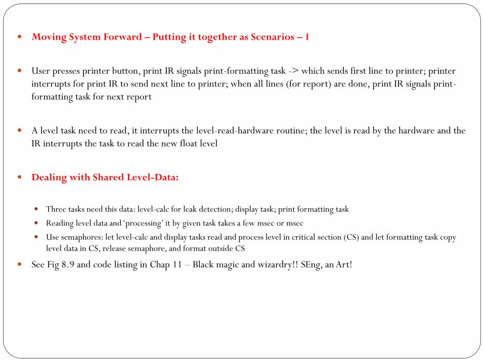
Moving System Forward – Putting it together as Scenarios – 1
User presses printer button, print IR signals print-formatting task -> which sends first line to printer; printer
interrupts for print IR to send next line to printer; when all lines (for report) are done, print IR signals print-
formatting task for next report
A level task need to read, it interrupts the level-read-hardware routine; the level is read by the hardware and the
IR interrupts the task to read the new float level
Dealing with Shared Level-Data:
Three tasks need this data: level-calc for leak detection; display task; print formatting task
Reading level data and ‘processing’ it by given task takes a few msec or msec
Use semaphores: let level-calc and display tasks read and process level in critical section (CS) and let formatting task copy
level data in CS, release semaphore, and format outside CS
See Fig 8.9 and code listing in Chap 11 – Black magic and wizardry!! SEng, an Art!

Encapsulating Semaphores and Queues
Encapsulating Semaphores:
Don’t assume that all tasks will use semaphore correctly (take/release), leading to errors
Protect semaphores and associated data – encapsulate/hide them in a task
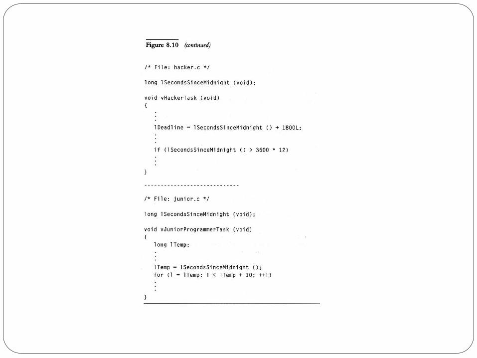
Let all tasks call a separate module (acting as an intermediary) to get to the CS - this separate
module/function will in turn call the task which encapsulates the semaphore
(See Fig 8.10 – the correct code)
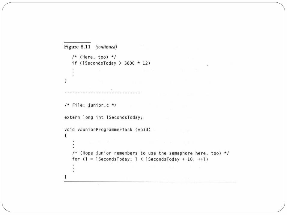
(See Fig 8.11 – the incorrect alternative, which bypasses the intermediate function


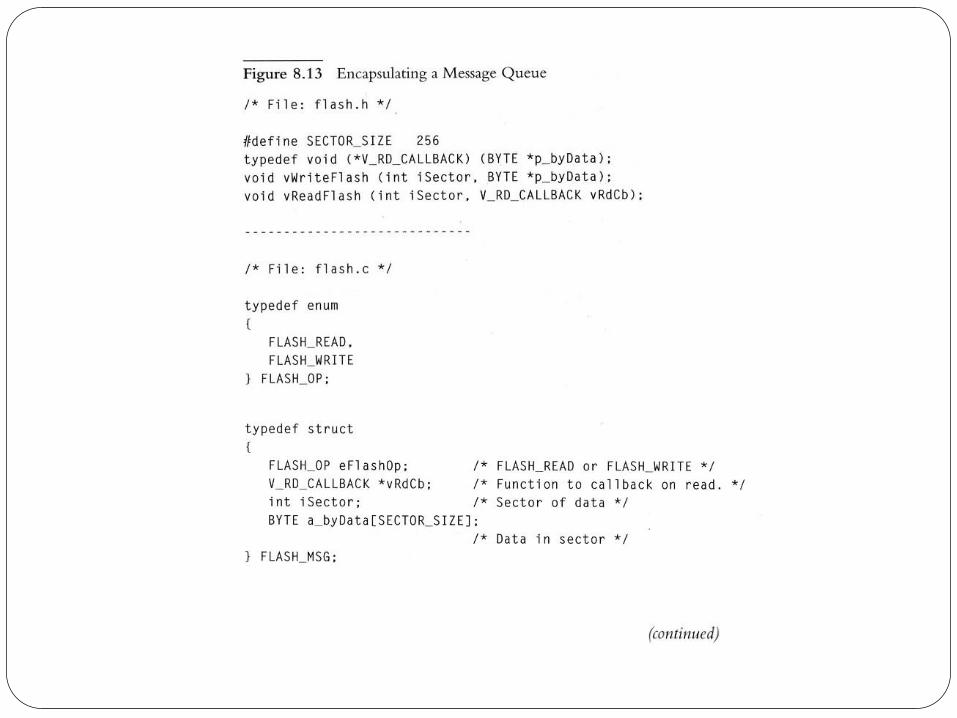
Encapsulating Semaphores and Queues
Encapsulating Queues:
Writing to or reading from a flash memory using queues to enqueue messages, the correctness of Fig 8.4
implementation depends passing the correct FLASH_MSG type
Can a message meant for the FLASH be enqueued elsewhere
Exposing the flash queue to inadvertent deletion or destruction
Extra layer of data queue for holding data read from the FLASH – could this auxiliary queue be referenced wrongly?
Type compatible with the FLASH content? …
Solution – Encapsulate the Flash Queue structure inside a separate module, flash.c; with access to it only through
intermediate task vHandleFlashTask, which is supported by auxiliary functions vReadFlash and vWriteFlash. [The
handle-task provides an interface for all other tasks to get to the queue]
(See Fig 8.13)


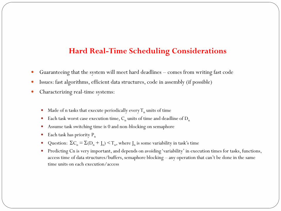
Hard Real-Time Scheduling Considerations
Guaranteeing that the system will meet hard deadlines – comes from writing fast code
Issues: fast algorithms, efficient data structures, code in assembly (if possible)
Characterizing real-time systems:
Made of n tasks that execute periodically every Tn units of time
Each task worst case execution time, Cn units of time and deadline of Dn
Assume task switching time is 0 and non-blocking on semaphore
Each task has priority Pn
Question: SCn = S(Dn + Jn) < Tn, where Jn is some variability in task’s time
Predicting Cn is very important, and depends on avoiding ‘variability’ in execution times for tasks, functions,
access time of data structures/buffers, semaphore blocking – any operation that can’t be done in the same
time units on each execution/access

Saving Memory Space
Considerations of limited memory space for ES systems
Code is stored in ROM (loaded into RAM for execution), Data is stored in RAM (except for
initialization/shadowing. The two memory space types are not interchangeable
Trade-offs: packed data saves RAM space, but unpacking code takes ROM space
Estimate space by:
A. Tasks take stack space, fewer tasks take less RAM space, inspect code to estimate stack-bytes per task –
local variables, parameters, function nesting-level, worst-case nesting of interrupt routines, space for the
RTOS (or select features) from the manual
B. Experimental runs of the code – not easy and won’t reflect worst-case behavior

Saving Memory Space – 1
Techniques / Suggestions:
Substitute or eliminate large functions, watch for repeated calls to large functions
Consider writing your own function to replace RTOS functions, watch RTOS functions that call several others
Configure or customize the RTOS functions to suit only the needs of the ES
Study assembly listing of cross-compilers, and rework your C code or write your own assembly unit/task
Use ‘static’ variable instead of relying on stack variables (push/pop and pointering takes space)
Copy data structures passed to a function, via a pointer, into the function’s local, static variables – process the data and copy
back into structures: trade-off – code is slower
For an 8-bit processor, use char instead of int variable (int takes 2-bytes and longer in calculations than 1-byte chars)
If ROM is really tight, experiment with coding most functions/tasks in assembly lang
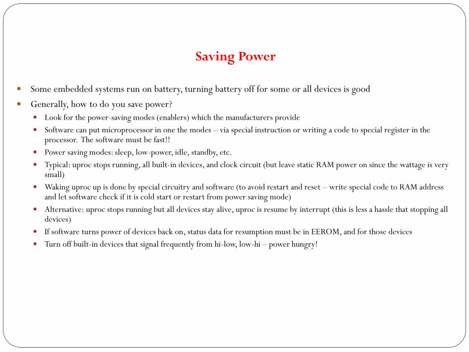
Saving Power
Some embedded systems run on battery, turning battery off for some or all devices is good
Generally, how to do you save power?
Look for the power-saving modes (enablers) which the manufacturers provide
Software can put microprocessor in one the modes – via special instruction or writing a code to special register in the processor. The software must be fast!!
Power saving modes: sleep, low-power, idle, standby, etc.
Typical: uproc stops running, all built-in devices, and clock circuit (but leave static RAM power on since the wattage is very small)
Waking uproc up is done by special circuitry and software (to avoid restart and reset – write special code to RAM address and let software check if it is cold start or restart from power saving mode)
Alternative: uproc stops running but all devices stay alive, uproc is resume by interrupt (this is less a hassle that stopping all devices)
If software turns power of devices back on, status data for resumption must be in EEROM, and for those devices
Turn off built-in devices that signal frequently from hi-low, low-hi – power hungry!
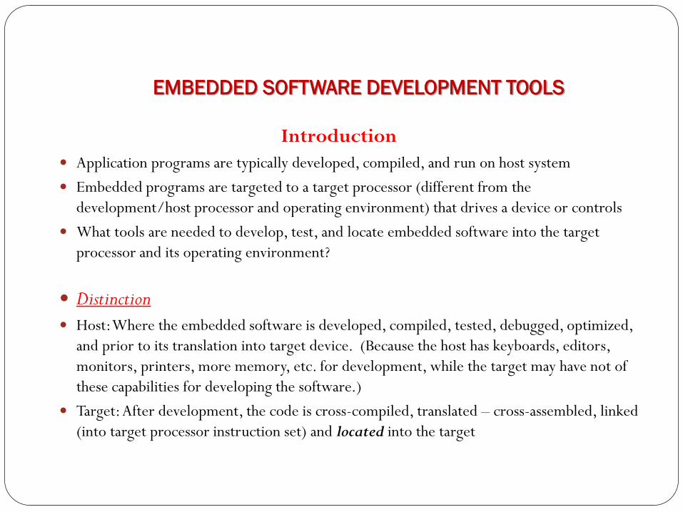
Introduction
Application programs are typically developed, compiled, and run on host system
Embedded programs are targeted to a target processor (different from the
development/host processor and operating environment) that drives a device or controls
What tools are needed to develop, test, and locate embedded software into the target
processor and its operating environment?
Distinction
Host: Where the embedded software is developed, compiled, tested, debugged, optimized,
and prior to its translation into target device. (Because the host has keyboards, editors,
monitors, printers, more memory, etc. for development, while the target may have not of
these capabilities for developing the software.)
Target: After development, the code is cross-compiled, translated – cross-assembled, linked
(into target processor instruction set) and located into the target
EMBEDDED SOFTWARE DEVELOPMENT TOOLS

Cross-Compilers – Native tools are good for host, but to port/locate embedded code to target, the host must have a tool-chain that
includes a cross-compiler, one which runs on the host but produces code for the target processor
Cross-compiling doesn’t guarantee correct target code due to (e.g., differences in word sizes, instruction sizes, variable
declarations, library functions)
Cross-Assemblers and Tool Chain Host uses cross-assembler to assemble code in target’s instruction syntax for the target
Tool chain is a collection of compatible, translation tools, which are ‘pipelined’ to produce a complete binary/machine
code that can be linked and located into the target processor
(See Fig 9.1)


Linker/Locators for Embedded Software Native linkers are different from cross-linkers (or locators) that perform additional tasks to locate embedded
binary code into target processors
Address Resolution – Native Linker: produces host machine code on the hard-drive (in a named file), which the loader loads into RAM, and then
schedules (under the OS control) the program to go to the CPU.
In RAM, the application program/code’s logical addresses for, e.g., variable/operands and function calls, are ordered or organized by the linker. The loader then maps the logical addresses into physical addresses – a process called address resolution. The loader then loads the code accordingly into RAM (see Fig 9.2). In the process the loader also resolves the addresses for calls to the native OS routines
Locator: produces target machine code (which the locator glues into the RTOS) and the combined code (called map) gets copied into the target ROM. The locator doesn’t stay in the target environment, hence all addresses are resolved, guided by locating-tools and directives, prior to running the code (See Fig 9.3 and Fig 9.4)


Locating Program Components – Segments
Unchanging embedded program (binary code) and constants must be kept in ROM to be remembered even
on power-off
Changing program segments (e.g., variables) must be kept in RAM
Chain tools separate program parts using segments concept
Chain tools (for embedded systems) also require a ‘start-up’ code to be in a separate segment and ‘located’
at a microprocessor-defined location where the program starts execution
Some cross-compilers have default or allow programmer to specify segments for program parts, but cross-
assemblers have no default behavior and programmer must specify segments for program parts
(See Fig 9.5 - locating of object-code segments in ROM and RAM)


Locating Program Components – Segments – 1
Telling/directing the locator where (which segments) to place parts
E.g., Fig 9.6
The –Z tells which segments (list of segments) to use and the start-address of the first segment
The first line tells which segments to use for the code parts, starting at address 0; and the second line tells which
segments to use for the data parts, starting at x8000
The proper names and address info for the directing the locator are usually in the cross-compiler documentation
Other directives: range of RAM and ROM addresses, end of stack address (segment is placed below this address
for stack to grow towards the end)
Segments/parts can also be grouped, and the group is located as a unit

Initialized Data and Constant Strings
Segments with initialized values in ROM are shadowed (or copied into RAM) for correct reset of
initialized variables, in RAM, each time the system comes up (esp. for initial values that are take
#define constants, and which can be changed)
In C programs, a host compiler may set all uninitialized variable to zero or null, but this is not generally
the case for embedded software cross-compilers (unless the startup code in ROM does so
If part(s) of a constant string is(are) expected to be changed during run-time, the cross-compiler must
generate a code to allow ‘shadowing’ of the string from ROM

Locator Maps and Executing Out of RAM
Output file of locators are Maps – list addresses of all segments
Maps are useful for debugging
An ‘advanced’ locator is capable of running (albeit slowly) a startup code in ROM, which (could
decompress and) load the embedded code from ROM into RAM to execute quickly since RAM is faster,
especially for RISC microprocessors
(See Fig 9.7 – Maps)


Getting Embedded Software into Target System
Moving maps into ROM or PROM, is to create a ROM using hardware tools or a PROM programmer
(for small and changeable software, during debugging)
If PROM programmer is used (for changing or debugging software), place PROM in a socket (which
makes it erasable – for EPROM, or removable/replaceable) rather than ‘burnt’ into circuitry
PROM’s can be pushed into sockets by hand, and pulled using a chip puller
The PROM programmer must be compatible with the format (syntax/semantics) of the Map
(See Fig 9.8)

Getting Embedded Software into Target System – 1
ROM Emulators – Another approach is using a ROM emulator (hardware) which emulates the target
system, has all the ROM circuitry, and a serial or network interface to the host system. The locator
loads the Map into the emulator, especially, for debugging purposes.
Software on the host that loads the Map file into the emulator must understand (be compatible with)
the Map’s syntax/semantics
(See Fig 9.9)


Getting Embedded Software into Target System – 2
Using Flash Memory
For debugging, a flash memory can be loaded with target Map code using a software on the host over a serial port
or network connection (just like using an EPROM)
Advantages:
No need to pull the flash (unlike PROM) for debugging different embedded code
Transferring code into flash (over a network) is faster and hassle-free
New versions of embedded software (supplied by vendor) can be loaded into flash memory by customers over a network -
Requires a) protecting the flash programmer, saving it in RAM and executing from there, and reloading into flash after new
version is written and b) the ability to complete loading new version even if there are crashes and protecting the startup code as in
(a)
Modifying and/or debugging the flash programming software requires moving it into RAM, modify/debug, and reloading it into
target flash memory using above methods

DEBUGGING TECHNIQUES
Introduction
Rule of Thumb: Write good, bug-free code from start if you could
Testing/Debugging embedded software is more difficult than application software
Post-shipment application problems are more tolerable than embedded (real-time or life-critical)
software

Testing on Host Machine
Some reasons why you can’t test (much, if any) on target machine:
Test early (target may not ready or completely stable)
Exercise all code, including exceptions (real situations may be difficult to exercise)
Develop reusable, repeatable test (difficult to do in target environment, and likelihood of hitting the
same bug is low)
Store test results (target may not even have disk drive to store results)

Testing on Host Machine – 1
Basic Techniques
Fig 10.1 –
Target system on the left: (hardware-indep code, hardware-dep code, hw)
Test system (on host) on the right: (hardware-indep code – same, scaffold – rest)
Scaffold provides (in software) all functionalities and calls to hardware as in the hardware-dep and hardware
components of the target system – more like a simulator for them!


Testing on Host Machine – 2
Basic Techniques
Fig 10.2 –
Radio.c -- hardware independent code
Radiohw.c – hardware dependent code (only interface to hw: inp() and outp() supporting
vTurnOnTransmitter() and vTurnOffTransmitter() functions
Inp() and outp() must have real hardware code to read/write byte data correctly - makes testing harder!!
Fig 10.3 –
Replace radiohw.c with scaffold, eliminating the need for inp() and outp() – both are simulated in software – a
program stub!!

Figure 10.2 A Poor Plan for Testing
/* File: radio.c */
void vRadioTask (void)
{...!! Complicated code to determine if turning on the radio now
!! is within FCC regulations....!! More complicated code to decide if turning on the radio now
!! makes sense in our protocol.
If (!! Time to send something on the radio)
{
vTurnOnTransmitter (FREQ_NORMAL);
!! Send data out
vTurnOffRadio ();
}
}
-----------------------------------------------
(continued)

Figure 10.2 (continued)
/* File: radiohw.c */
void vTurnOnTransmitter (int iFrequencyValue)
{
BYTE byPower; /* Byte read from device controlling power. */
int i;
/* Turn on main power for the radio. */
disable_interrupts ();
byPower = inp (PWR_CONTROL_ADDR);
byPower |= PWR_CONTROL_RADIO_MAIN;
outp (PWR_CONTROL_ADDR, byPower);
enable_interrupts ();
/* Shift the frequency value out to hardware. */
for (i = 0; i < 16; ++i)
{
/* Send out the lowest bit of iFrequencyValue */
if (iFrequencyValue & 0x0001)
{
/* The data is a binary 1 */
/* Put a '1' on the data line; pulse the clock line. */
outp (FRQ_CONROL, DATA_1 & CLOCK_LOW)
outp (FRQ_CONROL, DATA_1 & CLOCK_HIGH);
}
(continued)

Figure 10.2 (continued)
else
{
/* The data is a binary 0 */
/* put a '0' on the data line; pulse the clock line. */
outp (FRQ_CONROL, DATA_0 & CLOCK_LOW)
outp (FRQ_CONROL, DATA_0 & CLOCK_HIGH);
}
/* Shift iFrequencyValue to get the next lowest bit. */
iFrequencyValue >>= 1;
}
/* Turn on the receiver. */
byPower = inp (PWR_CONTROL_ADDR);
byPower |= PWR_CONTROL_RADIO_RECEIVER;
outp (PWR_CONTROL_ADDR, byPower);
enable_interrupts ();
}
void vTurnOffRadio (void)
{
BYTE byPower; /* Byte read from device controlling power. */
/* Turn off main power for the radio. */
disable_interrupts ();
byPower = inp (PWR_CONTROL_ADDR);
byPower &= ~PWR_CONTROL_RADIO_MAIN;
outp (PWR_CONTROL_ADDR, byPower);
enable_interrupts ();
}
------------------------------------------- (continued)

Figure 10.2 (continued) /* File: test.c */ void outp (int Address, BYTE byData)
{
#ifdef LET_USER_SIMULATE_HARDWARE
PRINTF ("program wrote %02x to %04x.", byData, iAddress);
#endif
#ifdef SIMULATE_HARDWARE
!! Remember that software wrote byData to iAddress
!! Update state of simulated hardware.
#endif
} BYTE inp (int iAddress)
{
int iData;
#ifdef LET_USER_SIMULATE_HARDWARE
PRINTF ("program wrote %02x to %04x. Enter value.",
iAddress);
scanf ("%x", &iData);
#endif
#ifdef SIMULATE_HARDWARE
!! Figure out what the real hardware would return
#endif
return ((BYTE) iData);
}

Figure 10.3 Better Plan for Testing
/* File: radio.c */
void vRadioTask (void)
{...!! Complicated code to determine if turning on the radio now
!! is within FCC regulations....!! More complicated code to decide if turning on the radio now
!! makes sense in our protocol.
If (!! Time to send something on the radio)
{
vTurnOnTransmitter (FREQ_NORMAL);
!! Send data out
vTurnOffRadio ();
}
}
-----------------------------------------------
(continued)
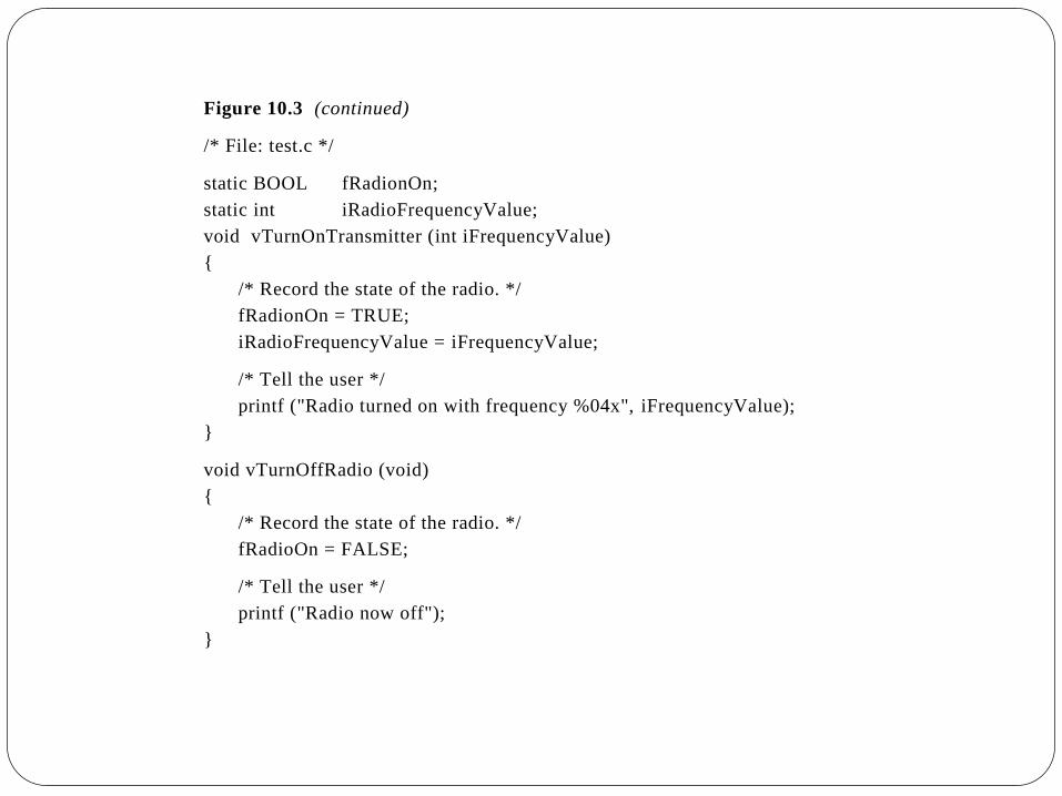
Figure 10.3 (continued)
/* File: test.c */
static BOOL fRadionOn;
static int iRadioFrequencyValue;
void vTurnOnTransmitter (int iFrequencyValue)
{
/* Record the state of the radio. */
fRadionOn = TRUE;
iRadioFrequencyValue = iFrequencyValue;
/* Tell the user */
printf ("Radio turned on with frequency %04x", iFrequencyValue);
}
void vTurnOffRadio (void)
{
/* Record the state of the radio. */
fRadioOn = FALSE;
/* Tell the user */
printf ("Radio now off");
}

Testing on Host Machine – 3
Calling Interrupt Routines –
Embedded systems are interrupt-driven, so to test based on interrupts
1) Divide interrupt routines into two components
A) a component that deals with the hardware
B) a component of the routine which deals with the rest of the system
2) To test, structure the routine such that the hardware-dependent component (A) calls the hardware-independent part
(B).
3) Write component B in C-language, so that the test scaffold can call it
E.g., Fig 10.4 –
Hw component (A) is vHandleRxHardware(), which reads characters from the hw
Sw component (B) is vHandleByte, called by A to buffer characters, among others
The test scaffold, vTestMain(), then calls vHandleByte(), to test if the system works [where vTestMain() pretends to be
the hardware sending the chars to vHandleByte()]
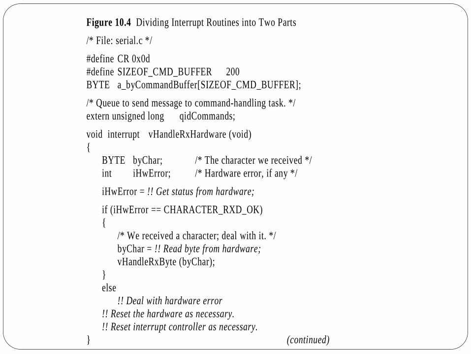
Figure 10.4 Dividing Interrupt Routines into Two Parts
/* File: serial.c */
#define CR 0x0d
#define SIZEOF_CMD_BUFFER 200
BYTE a_byCommandBuffer[SIZEOF_CMD_BUFFER];
/* Queue to send message to command-handling task. */
extern unsigned long qidCommands;
void interrupt vHandleRxHardware (void)
{
BYTE byChar; /* The character we received */
int iHwError; /* Hardware error, if any */
iHwError = !! Get status from hardware;
if (iHwError == CHARACTER_RXD_OK)
{
/* We received a character; deal with it. */
byChar = !! Read byte from hardware;
vHandleRxByte (byChar);
}
else
!! Deal with hardware error
!! Reset the hardware as necessary.
!! Reset interrupt controller as necessary.
} (continued)
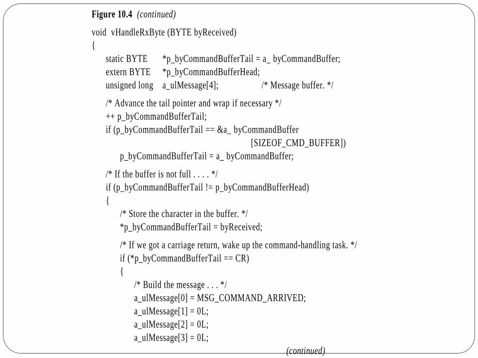
Figure 10.4 (continued)
void vHandleRxByte (BYTE byReceived)
{
static BYTE *p_byCommandBufferTail = a_ byCommandBuffer;
extern BYTE *p_byCommandBufferHead;
unsigned long a_ulMessage[4]; /* Message buffer. */
/* Advance the tail pointer and wrap if necessary */
++ p_byCommandBufferTail;
if (p_byCommandBufferTail == &a_ byCommandBuffer
[SIZEOF_CMD_BUFFER])
p_byCommandBufferTail = a_ byCommandBuffer;
/* If the buffer is not full . . . . */
if (p_byCommandBufferTail != p_byCommandBufferHead)
{
/* Store the character in the buffer. */
*p_byCommandBufferTail = byReceived;
/* If we got a carriage return, wake up the command-handling task. */
if (*p_byCommandBufferTail == CR)
{
/* Build the message . . . */
a_ulMessage[0] = MSG_COMMAND_ARRIVED;
a_ulMessage[1] = 0L;
a_ulMessage[2] = 0L;
a_ulMessage[3] = 0L;
(continued)

Figure 10.4 (continued)
/* . . . and send it. */
q_send (qidCommands, a_ulMessage);
}
}
else
{
/* Discard the character; move the pointer back. */
if (p_byCommandBufferTail == a_ byCommandBuffer)
p_byCommandBufferTail ==
&a_ byCommandBuffer[SIZEOF_CMD_BUFFER];
-- p_byCommandBufferTail;
}
}
--------------------------------------------
/* File: test.c */
void vTestMain (void)
{
BYTE a_byTestCommand[] = "THUMBS UP\x0dSIMON SAYS THUMBS UP\x0d";
BYTE *p_by;../* Send each of the characters in a_byTestCommand */
p_by = a_byTestCommand;
while (*p_by)
{
/* Send a single character as though received by the interrupt */
vHandleRxByte (*p_by);
/* Go to the next character */
++p_by;
}..
}

Testing on Host Machine – 4
Calling the Timer Interrupt Routine
Design the test scaffold routine to directly call the timer interrupt routine, rather than other part of the host
environment, to avoid interruptions in the scaffold’s timing of events
This way, the scaffold has control over sequences of events in the test which must occur within intervals of timer
interrupts
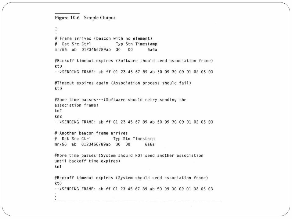
Script Files and Output Files
To let the scaffold test the system in some sequence or repeated times, write a script file (of commands and
parameters) to control the test
Parse the script file, test system based on commands/parameters, and direct output – intermixture of the input-
script and output lines – into an output file
The commands in the script cause the scaffold to call routines in the B (sw-indp) component -- See Fig 10.5 and
Fig 10.6 – for the cordless bar-code scanner


Testing on Host Machine – 5
More Advanced Techniques
Making the scaffold automatically control sequence of events – e.g., calling the printer interrupt many times but in
a controlled order to avoid swamping
Making the scaffold automatically queue up requests-to-send output lines, by automatically controlling the button
interrupt routine, which will cause successive pressing of a button to let the next output line be received from the
hardware (the printer interrupt routine). In this way, the hardware-independent software is controlled by the
scaffold, where the button interrupts serve as a switch
The scaffold may contain multiple instances of the software-independent code, and the scaffold serves as a controller
of the communication between the instances – where each instance is called by the scaffold when the hardware
interrupt occurs (e.g., the scanner or the cash register). In this way, the scaffold simulates the hardware (scanner or
register) and provides communication services to the software-independent code instances it calls. – See Fig 10.7

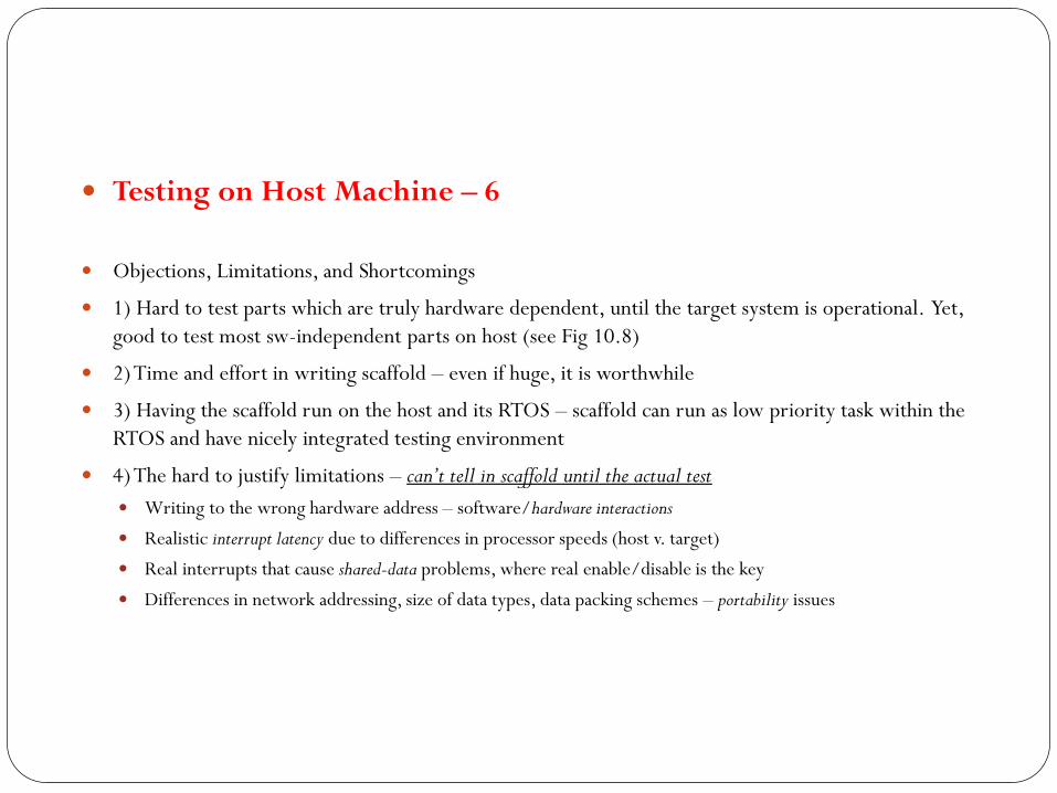
Testing on Host Machine – 6
Objections, Limitations, and Shortcomings
1) Hard to test parts which are truly hardware dependent, until the target system is operational. Yet,
good to test most sw-independent parts on host (see Fig 10.8)
2) Time and effort in writing scaffold – even if huge, it is worthwhile
3) Having the scaffold run on the host and its RTOS – scaffold can run as low priority task within the
RTOS and have nicely integrated testing environment
4) The hard to justify limitations – can’t tell in scaffold until the actual test
Writing to the wrong hardware address – software/hardware interactions
Realistic interrupt latency due to differences in processor speeds (host v. target)
Real interrupts that cause shared-data problems, where real enable/disable is the key
Differences in network addressing, size of data types, data packing schemes – portability issues

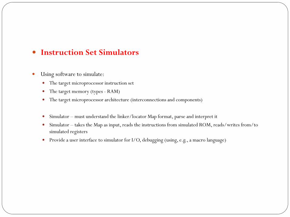
Instruction Set Simulators
Using software to simulate:
The target microprocessor instruction set
The target memory (types - RAM)
The target microprocessor architecture (interconnections and components)
Simulator – must understand the linker/locator Map format, parse and interpret it
Simulator – takes the Map as input, reads the instructions from simulated ROM, reads/writes from/to
simulated registers
Provide a user interface to simulator for I/O, debugging (using, e.g., a macro language)

Instruction Set Simulators – 1
Capabilities of Simulators:
Collect statistics on # instructions executed, bus cycles for estimating actual times
Easier to test assembly code (for startup software and interrupt routines) in simulator
Easier to test for portability since simulator takes same Map as the target
Other parts, e.g., timers and built-in peripherals, can be tested in the corresponding simulated versions in the
simulated microprocessor architecture
What simulators can’t help:
Simulating and testing ASICs, sensors, actuators, specialized radios (perhaps, in future systems!!)
Lacking I/O interfaces in simulator to support testing techniques discussed (unless additional provision is made for
I/O to support the scaffold; and scripts to format and reformat files between the simulator, simulated memory, and
the scaffold)

The assert Macro
The assert is used (with a boolean-expression parameter) to check assumptions
If the expression is TRUE nothing happens, if FALSE, a message is printed and the program crashes
Assert works well in finding bugs early, when testing in the host environment
On failure, assert causes a return to the host operating systems (can’t do on target, and can’t print such
message on target – may not have the display unit)
Assert macro that runs on the target are useful for spotting problems:
1) disabling interrupts and spin in infinite loop – effectively stopping the system
2) turn on some pattern of LEDs or blinking device
3) write special code memory for logic analyzer to read
4) write location of the instruction that cause problem to specific memory for logic analyzer to read (the Map can
help isolate which source code is the culprit!)
5) execute an illegal op or other to stop the system – e.g., using in-circuit emulators

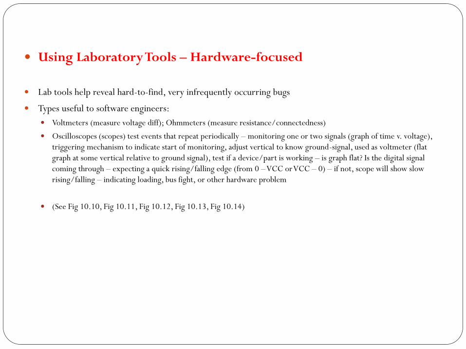
Using Laboratory Tools – Hardware-focused
Lab tools help reveal hard-to-find, very infrequently occurring bugs
Types useful to software engineers:
Voltmeters (measure voltage diff); Ohmmeters (measure resistance/connectedness)
Oscilloscopes (scopes) test events that repeat periodically – monitoring one or two signals (graph of time v. voltage),
triggering mechanism to indicate start of monitoring, adjust vertical to know ground-signal, used as voltmeter (flat
graph at some vertical relative to ground signal), test if a device/part is working – is graph flat? Is the digital signal
coming through – expecting a quick rising/falling edge (from 0 – VCC or VCC – 0) – if not, scope will show slow
rising/falling – indicating loading, bus fight, or other hardware problem
(See Fig 10.10, Fig 10.11, Fig 10.12, Fig 10.13, Fig 10.14)


Using Laboratory Tools – Hardware-focused - 1
Logic Analyzer
Like storage scopes that (first) capture many signals and displays them simultaneously
It knows only of VCC and ground voltage levels (displays are like timing diagrams) – Real scopes display exact
voltage (like analog)
Can be used to trigger on-symptom and track back in stored signal to isolate problem
Many signals can be triggered at their low and/or high points and for how long in that state
Used in Timing or State Mode
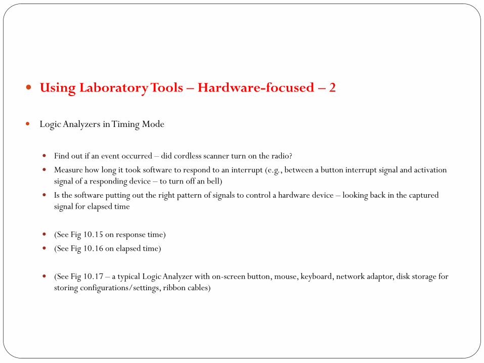
Using Laboratory Tools – Hardware-focused – 2
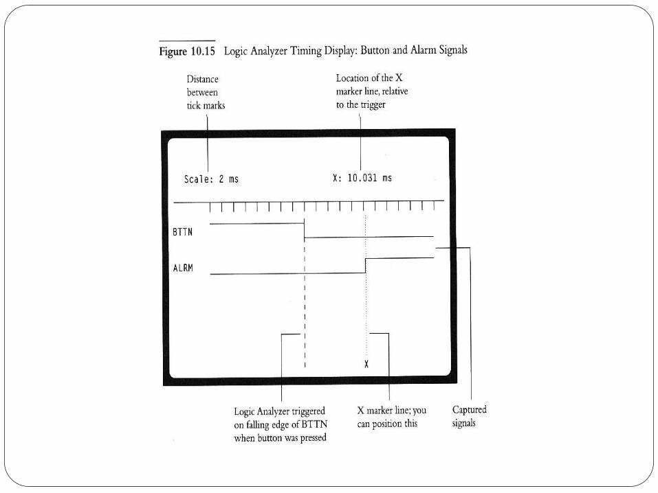
Logic Analyzers in Timing Mode
Find out if an event occurred – did cordless scanner turn on the radio?
Measure how long it took software to respond to an interrupt (e.g., between a button interrupt signal and activation
signal of a responding device – to turn off an bell)
Is the software putting out the right pattern of signals to control a hardware device – looking back in the captured
signal for elapsed time
(See Fig 10.15 on response time)
(See Fig 10.16 on elapsed time)
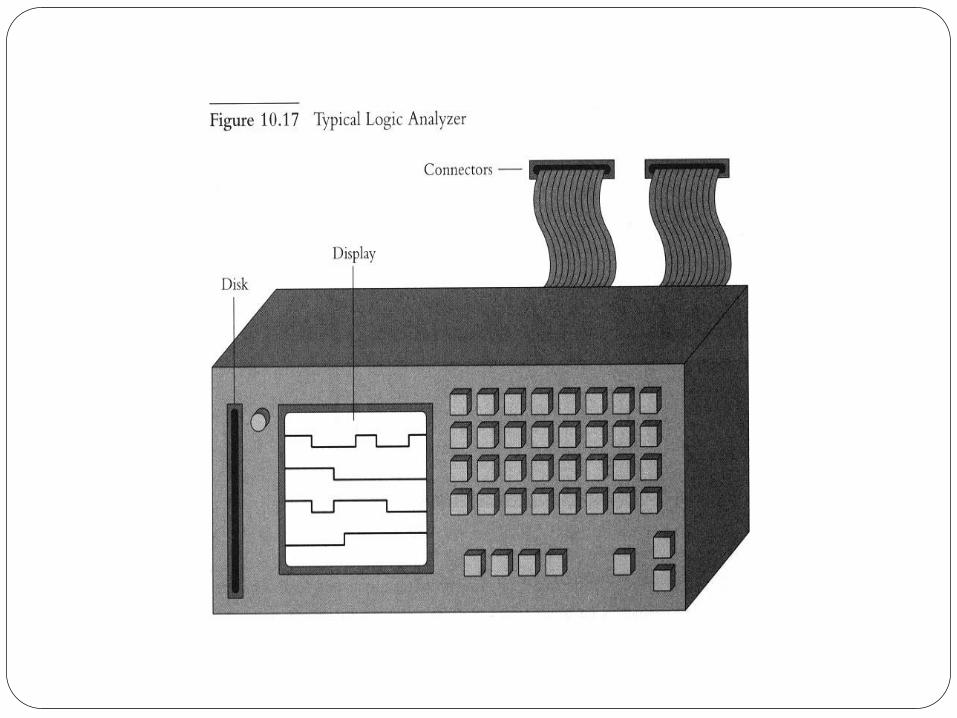
(See Fig 10.17 – a typical Logic Analyzer with on-screen button, mouse, keyboard, network adaptor, disk storage for
storing configurations/settings, ribbon cables)

Using Laboratory Tools – Hardware-focused – 3
Logic Analyzers in State Mode
Captures signals only on clock-event occurring from the attached hardware
Typical use: instructions read/fetched by microprocessor, data read from or written to ROM, RAM, or I/O devices
To do so, connect LA to address and data signals and RE/ signal on the ROM (or RAM)
If triggering is on rising edge of RE/ pin, address and data signals will be captured
Output of LA, called trace, is stored for later analysis – see Fig 10.18
LA can be triggered on unusual event occurrences, then capture signals therefrom – especially for debugging
purposes (e.g., writing data to wrong address, tracking a rarely occurring bug, filtering signals for select devices or
events)
LA can’t capture all signals, e.g., on fetch from caches, registers, un-accessed memory


Using Laboratory Tools – Hardware-focused – 4
In-Circuit Emulators (ICE)
Replaces target microprocessor in target circuitry (with some engineering)
Has all the capabilities of a software debugger
Maintains trace, similar to that of an LA’s
Has overlay memory to emulate ROM and RAM for a specified range of address within the ICE (rather than the
system’s main ROM or RAM) – facilitates debugging
ICE v. LA
LA’s have better trace and filtering mechanism, and easier to detail and find problems
LA’s run in timing mode
LA’s work with any microprocessor – ICE is microprocessor-specific
LA’s support many but select signals to attach, ICE requires connecting ALL signals
ICE is more invasive

Using Laboratory Tools – Hardware-focused – 5
Hardware Peculiarities that Make Debugging Difficult
Inter-pin distances/intervals for attaching probes – getting smaller
Providing sockets for debugging hardware – simply increases product size
ASIC’s encase signals that are hard to probe and track using LA’s or ICE’s
Use of RISC architectural designs makes it difficult to track when read/write happen in on-board (microprocessor)
caches – different from the external RAM or ROM
Increasingly necessary to know the lab tool chain as it influences the design of product
Using Laboratory Tools – Hardware-focused – 6
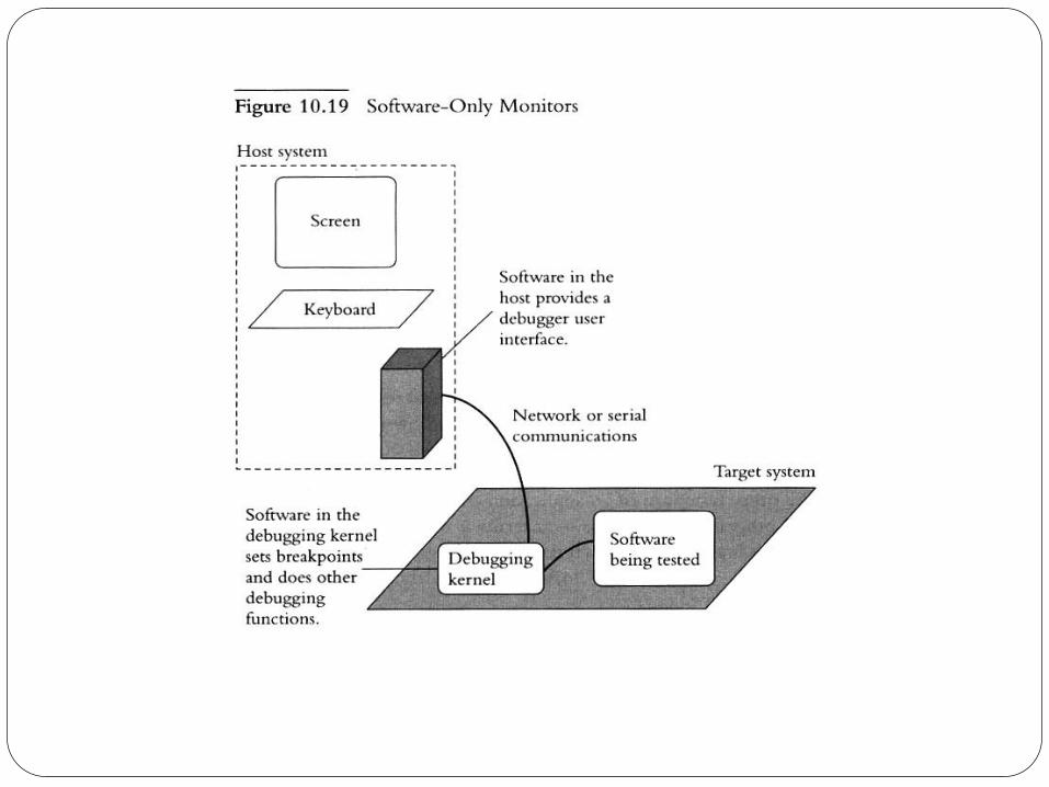
Software-Only Monitors
Monitors allow running an embedded system in the target environment, while providing debugging interfaces on both
the host and target environments
A small portion of the Monitor resides in the target ROM (debugging kernel or monitor):
The codes receives programs from serial port, network, copies into target’s RAM, and run it with full debugging capabilities to
test/debug the programs
Another portion of monitor resides on host – provides debugging capability and communicates with the debugging
kernel over serial port or network, without hardware modifications
Compiled, linked (may be located into Map) code is downloaded from the host (by the portion on the host) to the target
RAM or flash (received by the kernel)
Other designs: ROM Emulator interface and JPAG comm. port on the target processor
(See Fig 10.19)