unified analysis of internal flowfield in an integrated ...2014,sung)-part i.pdf · unified...
TRANSCRIPT
Unified Analysis of Internal Flowfield in an IntegratedRocket Ramjet Engine. I: Transition from Rocket
Booster to Ramjet SustainerHong-Gye Sung1 and Vigor Yang2
Abstract: A comprehensive numerical analysis was conducted to study the internal flow development in an integrated rocket-ramjet (IRR)propulsion system. The study consists of two parts: transition from the rocket booster to the ramjet sustainer and combustion dynamics duringramjet operation. The physical model of concern includes the entire IRR flow path, extending from the leading edge of the inlet center bodythrough the exhaust nozzle. The theoretical formulation is based on the Farve-averaged conservation equations of mass, momentum, energy,and species concentration in axisymmetric coordinates and accommodates finite-rate chemical kinetics and variable thermophysical properties.Turbulence closure is achieved using a low-Reynolds-number k-ɛ two-equation model. The governing equations are solved numerically bymeans of a finite-volume preconditioned flux-differencing scheme capable of treating a chemically reacting flow over a wide range of Machnumbers. Various important physiochemical processes involved in the transition from the booster to the sustainer phase are investigatedsystemically. Emphasis is placed on the flow interactions between the inlet diffuser and combustor. The effects of operation timing on the flowevolution, fuel spread, ignition, and flame development are studied.DOI: 10.1061/(ASCE)AS.1943-5525.0000255.© 2014 American Societyof Civil Engineers.
Author keywords: Integrated rocket ramjet engine; Ignition transients; Supersonic aerodynamics.
Introduction
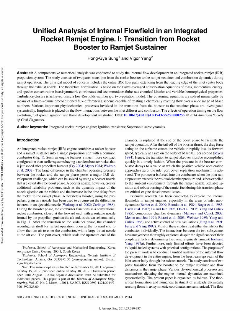
An integrated rocket-ramjet (IRR) engine combines a rocket boosterand a ramjet sustainer into a single propulsion unit with a commoncombustor (Fig. 1). Such an engine features a much more compactconfiguration than earlier systems having a tandembooster rocket thatis jettisoned after propellant burnout (Fry 2004;Myers 1984;Waltrupet al. 2002). The large difference in the chamber operating pressurebetween the rocket and the ramjet phase poses a major IRR de-velopment challenge, which can be solved by using a booster nozzlethat is ejected after the boost phase.Abooster nozzle, however, createsadditional reliability problems, such as the dynamic impact of thenozzle ejection on the vehicle and the increase in the time delay fromthe rocket to the ramjet phase. A nozzleless booster, using the pro-pellant grain as a nozzle, has been used to circumvent the difficultiesinherent in an ejectable nozzle (Waltrup et al. 2002; Zarlingo 1988).During the booster phase, the combustor functions as a conventionalrocket combustor, closed at the forward end, with a suitable nozzleformed by the propellant grain at the aft end, as shown schematicallyin Fig. 1. After the transition to the sustainer phase, the chamberreconfigures itself for ramjet operation, open at the forward end toallow the ram air to enter the combustor, with a large-throat nozzleat the aft end. The port cover, which seals the upstream end of the
chamber, is ruptured at the end of the boost phase to facilitate theramjet operation. After the tail-off of the booster thrust, the drag forceacting on the airframe causes the vehicle to rapidly lose its forwardspeed, typically at a rate on the order of Mach 0.1 per second (Myers1984). Hence, the transition to ramjet takeover must be accomplishedquickly in a timely fashion. When the pressure in the booster com-bustor decays to a value at which the positive vehicle accelerationapproaches zero, the inlet port cover separation mechanism is acti-vated. The port cover is forced into the combustor when the inlet ramair pressure exceeds the residual chamber pressure and is then expelledto the ambient environment through the ramjet nozzle. Reliable ig-nition and robust burning of the ramjet fuel during this transient phaseare critical engine development issues.
Extensive research has been conducted to explore the internalflowfields in ramjet engines, especially in the areas of inlet aero-dynamics (Barber et al. 2009; Bemdot et al. 1984; Bogar et al. 1985;Hsieh et al. 1987; Lu and Jain 1998; Oh et al. 2005; Yang and Culick1985), combustion chamber dynamics (Matveev and Culick 2003;Menon and Jou 1991; Ristori et al. 2003; Webster 1989; Yang andCulick 1986), and active control of flow oscillations (Fung et al. 1991;Fung and Yang 1992). Most of these studies treat either the inlet or thecombustor individually. The interactions between the two subsystemshave not yet been thoroughly explored, despite the significance of theircoupling effects indetermining theoverall enginedynamics (Hsieh andYang 1997a). Furthermore, only limited efforts have been devotedto liquid-fueled systems with practical configurations. The purpose ofthe present work is to conduct a unified analysis of the internal flowdevelopment in the entire engine, from the freestream upstream of theinlet center body through the exhaust nozzle. The study consists of twoparts: transition from the booster to the ramjet sustainer and flowdynamics in the ramjet phase. Various physiochemical processes andmechanisms dictating the engine internal dynamics are examinedsystematically. The present paper is organized as follows. The theo-retical formulation and numerical treatment of unsteady chemicallyreacting flows in axisymmetric coordinates are summarized. The flow
1Professor, School of Aerospace and Mechanical Engineering, KoreaAerospace Univ., Geonggi 200-1, South Korea.
2Professor, School of Aerospace Engineering, Georgia Institute ofTechnology, Atlanta, GA 30332-0150 (corresponding author). E-mail:[email protected]
Note. This manuscript was submitted on November 18, 2011; approvedon May 15, 2012; published online on May 18, 2012. Discussion periodopen until August 1, 2014; separate discussions must be submitted forindividual papers. This paper is part of the Journal of Aerospace Engi-neering, Vol. 27, No. 2, March 1, 2014. ©ASCE, ISSN 0893-1321/2014/2-390–397/$25.00.
390 / JOURNAL OF AEROSPACE ENGINEERING © ASCE / MARCH/APRIL 2014
J. Aerosp. Eng. 2014.27:390-397.
Dow
nloa
ded
from
asc
elib
rary
.org
by
GE
OR
GIA
TE
CH
LIB
RA
RY
on
03/0
3/14
. Cop
yrig
ht A
SCE
. For
per
sona
l use
onl
y; a
ll ri
ghts
res
erve
d.
transients from the booster to the sustainer phase are presented in thesection, “Flow Transients from Booster to Sustainer.” The situationwith the inlet port cover in place is also considered, to provide a morecomplete description. The ignition transients after the removal of theport cover are treated. The phenomena of fuel injection, mixing ofreactants, ignition, and flame evolution in the chamber are examined.
Theoretical Formulation and Numerical Treatment
Governing Equations
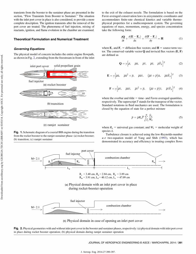
The physical model of concern includes the entire engine flowpath,as shown inFig. 2, extending from the freestream in front of the inlet
to the exit of the exhaust nozzle. The formulation is based on theFavre-averaged conservation laws in axisymmetric coordinates andaccommodates finite-rate chemical kinetics and variable thermo-physical properties for a multicomponent system. The governingequations of mass, momentum, energy, and species concentrationtake the following form:
∂Q∂t
þ ∂ðE2EvÞ∂x
þ ∂ðF2FvÞ∂y
¼ H (1)
whereEv and Fv 5 diffusion flux vectors; andH5 source term vec-tor. The conserved variable vectorQ and inviscid flux vectors (E, F)are defined as
Q ¼ yhr, r~u, r~v, r~e, r~Yk
iT (2)
E ¼ yhr~u, r~u2 þ p, r~u~v,
�r~eþ p
�~u, r~u~Yk
iT (3)
F ¼ yhr~v, r~u~v, r~v2 þ p,
�r~eþ p
�~v, r~v~Yk
iT (4)
where the overbar and tilde5 time- and Favre-averaged quantities,respectively. The superscript T stands for the transpose of the vector.Standard notations in fluid mechanics are used. The formulation isclosed by the equation of state for a perfect mixture
p ¼ rRuTPNk51
~Yk
Wk(5)
where Ru 5 universal gas constant; and Wk 5 molecular weight ofspecies k.
Turbulence closure is achieved using the low-Reynolds-numberk-ɛ two-equation model of Yang and Shih (1993), which hasdemonstrated its accuracy and efficiency in treating complex flows
Fig. 1.Schematic diagram of a coaxial IRR engine during the transitionfrom the rocket booster to the ramjet sustainer phase: (a) rocket booster;(b) transition; (c) ramjet sustainer
Fig. 2. Physical geometries with andwithout inlet port cover in the booster and sustainer phases, respectively: (a) physical domainwith inlet port coverin place during rocket booster operation; (b) physical domain during ramjet sustainer operation
JOURNAL OF AEROSPACE ENGINEERING © ASCE / MARCH/APRIL 2014 / 391
J. Aerosp. Eng. 2014.27:390-397.
Dow
nloa
ded
from
asc
elib
rary
.org
by
GE
OR
GIA
TE
CH
LIB
RA
RY
on
03/0
3/14
. Cop
yrig
ht A
SCE
. For
per
sona
l use
onl
y; a
ll ri
ghts
res
erve
d.
over a wide range of Reynolds numbers. The approach includesa time scale–based k-ɛ model for the near-wall turbulence to avoidthe singularity at the wall. Adaptation to separated flows is made byusing a damping function based on the Reynolds number instead ofy1. The model is designed to maintain the high Reynolds numberformulation in the logarithmic law region and is further tuned to fitexperimental data for the viscous and buffer layers.
The one-step global kinetics scheme proposed byWestbrook andDryer (1981) is adopted in light of its simplicity and reasonablyaccurate modeling of hydrocarbon flames in air. The overall reactionmechanism for the combustion of hydrocarbon fuel (CxHy) with airis written as
CxHy þ aðO2 þ 3:76N2Þ→ xCO2 þ ðy=2ÞH2Oþ bO2 þ 3:76aN2
(6)
where the coefficients a and b are determined by the fuel formulaand mixture composition. The reaction rate of the fuel takes thefollowing Arrhenius form:
_vCxHy ¼ ATm exp
�2 ERuT
��CxHy
�a½O2�b (7)
The consumption rates of other species can be obtained from theoverall reactionmechanism [Eq. (6)]. In this study, propane (C3H8) isselected as a fuel. The frequency factor A is 1:423 1011 m3=kmol×s,and the activation energy E is 125:52 kJ=mol (30 kcal=mol). Theexponents a, b, and m have values of 0.1, 1.65, and 0, respectively(Zarlingo 1988). The unit of _vCxHy is kg=m
3s.
Physical Domain and Boundary Conditions
Fig. 2 shows the IRR engine under consideration, consisting of anaxisymmetric mixed-compression supersonic inlet, a dump com-bustion chamber, a fuel injection unit, a port cover, and an exhaustnozzle. The projected cowl radius Rc is 3.4 cm, and the length ofthe inlet diffuser is 40.12 cm. The combustion chamber measures38.93 cm in length and 7.786 cm in radius, and the nozzle length is8.16 cm. The throat area of the inlet diffuser Ati is fixed at 0.615 Ac
and that of the exhaust nozzle Atn at 1.322 Ac, where Ac is theprojected area of the cowl, Ac [pR2
c . Detailed information aboutthe cowl and center body geometries is given inOh et al. (2005). Thefreestream conditions include a Mach number of 2.1 and an altitudeof 2.5 km. The corresponding temperature and pressure are 272 Kand 74.98 kPa, respectively, and the stagnation temperature andpressure are 512 K and 6.77 atm, respectively.
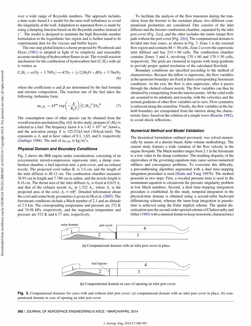
To facilitate the analysis of the flow transients during the tran-sition from the booster to the sustainer phase, two different com-putational geometries are considered. One consists of the inletdiffuser and the booster combustion chamber, separated by the inletport cover [Fig. 2(a)], and the other includes the entire ramjet flowpath without the port cover [Fig. 2(b)]. The computational domain isdivided into four zones, as shown in Fig. 3. Zone 1 is the externalflow region and contains 883 50 cells. Zone 2 covers the supersonicinlet diffuser and has 2143 60 cells. The combustion chambercontains Zones 3 and 4, involving 1703 60 and 1703 50 cells,respectively. The grids are clustered in regions with steep gradientsto provide proper spatial resolution of the calculated flowfield.
Boundary conditions are specified according to the method ofcharacteristics. Because the inflow is supersonic, the flow variablesat the upstream boundary are fixed at their corresponding freestreamconditions. At the exit, the flow is also supersonic, after it passesthrough the choked exhaust nozzle. The flow variables can thus beobtained by extrapolating from the interior points. All the solid wallsare assumed to be adiabatic and nonslip, with the velocities and thenormal gradients of other flow variables set to zero. Flow symmetryis enforced along the centerline. Finally, the flow variables at the far-field boundary are extrapolated from the interior along the charac-teristic lines, based on the solution of a simple wave (Roache 1982),to avoid shock reflections.
Numerical Method and Model Validation
The theoretical formulation outlined previously was solved numeri-cally by means of a density-based, finite-volume methodology. Thecurrent study features a wide variation of the flow velocity in theengine flowpath. The Mach number ranges from 2.1 in the freestreamto a low value in the dump combustor. The resulting disparity of theeigenvalues of the governing equations may cause serious numericalstiffness and convergence problems. To overcome this difficulty,a preconditioning algorithm augmented with a dual time-steppingintegration procedure is used (Hsieh and Yang 1997b). The methodproceeds in two steps. First, a rescaled pressure term is used in themomentum equation to circumvent the pressure singularity problemat low Mach numbers. Second, a dual time-stepping integrationprocedure is established. In this study, temporal integration in thephysical-time domain is obtained using a second-order backwarddifferencing scheme, whereas the inner-loop integration in pseudo-time is achieved using the Euler implicit scheme. The spatial dis-cretization uses the second-order upwind schemeofChakravarthy andOsher (1985)with aminmod limiter to keepmonotonic characteristics
Fig. 3. Computational domains for cases with and without inlet port cover: (a) computational domain with an inlet port cover in place; (b) com-putational domain in case of opening an inlet port cover
392 / JOURNAL OF AEROSPACE ENGINEERING © ASCE / MARCH/APRIL 2014
J. Aerosp. Eng. 2014.27:390-397.
Dow
nloa
ded
from
asc
elib
rary
.org
by
GE
OR
GIA
TE
CH
LIB
RA
RY
on
03/0
3/14
. Cop
yrig
ht A
SCE
. For
per
sona
l use
onl
y; a
ll ri
ghts
res
erve
d.
for convective terms and a second-order central differencing schemefor viscous terms. Finally, the alternating-direction-implicit scheme isused to treat the discretized governing equations in the block penta-diagonal matrix form. The overall algorithm was optimized to min-imize the computational time and memory requirements.
The numerical approach has been validated against a variety offlow problems to assess its accuracy. These include the aero-dynamics in an isentropic compression inlet (Hsieh and Yang1997a), shock/acoustic wave interactions (Yang and Culick 1985),solid-propellant rocket motor interior flows (Roh et al. 1995), andflow instabilities in porous chambers (Apte and Yang 2003). In eachof these studies, good agreement was obtained with either analyticalsolutions or experimental data.
Flow Transients from Booster to Sustainer
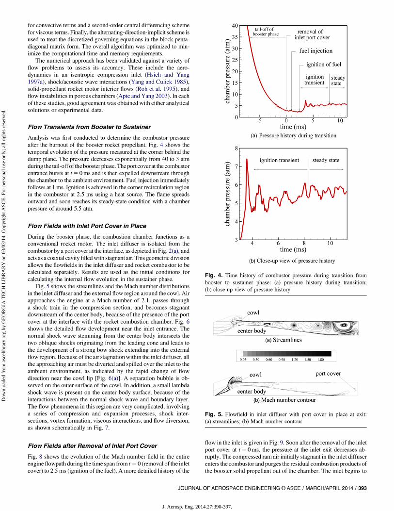
Analysis was first conducted to determine the combustor pressureafter the burnout of the booster rocket propellant. Fig. 4 shows thetemporal evolution of the pressure measured at the corner behind thedump plane. The pressure decreases exponentially from 40 to 3 atmduring the tail-off of thebooster phase.Theport cover at the combustorentrance bursts at t5 0ms and is then expelled downstream throughthe chamber to the ambient environment. Fuel injection immediatelyfollows at 1 ms. Ignition is achieved in the corner recirculation regionin the combustor at 2.5 ms using a heat source. The flame spreadsoutward and soon reaches its steady-state condition with a chamberpressure of around 5.5 atm.
Flow Fields with Inlet Port Cover in Place
During the booster phase, the combustion chamber functions as aconventional rocket motor. The inlet diffuser is isolated from thecombustor by a port cover at the interface, as depicted in Fig. 2(a), andacts as a coaxial cavityfilledwith stagnant air. This geometric divisionallows the flowfields in the inlet diffuser and rocket combustor to becalculated separately. Results are used as the initial conditions forcalculating the internal flow evolution in the sustainer phase.
Fig. 5 shows the streamlines and the Mach number distributionsin the inlet diffuser and the external flow region around the cowl. Airapproaches the engine at a Mach number of 2.1, passes througha shock train in the compression section, and becomes stagnantdownstream of the center body, because of the presence of the portcover at the interface with the rocket combustion chamber. Fig. 6shows the detailed flow development near the inlet entrance. Thenormal shock wave stemming from the center body intersects thetwo oblique shocks originating from the leading cone and leads tothe development of a strong bow shock extending into the externalflow region. Because of the air stagnationwithin the inlet diffuser, allthe approaching air must be diverted and spilled over the inlet to theambient environment, as indicated by the rapid change of flowdirection near the cowl lip [Fig. 6(a)]. A separation bubble is ob-served on the outer surface of the cowl. In addition, a small lambdashock wave is present on the center body surface, because of theinteractions between the normal shock wave and boundary layer.The flow phenomena in this region are very complicated, involvinga series of compression and expansion processes, shock inter-sections, vortex formation, viscous interactions, and flow diversion,as shown schematically in Fig. 7.
Flow Fields after Removal of Inlet Port Cover
Fig. 8 shows the evolution of the Mach number field in the entireengineflowpath during the time span from t5 0 (removal of the inletcover) to 2.5 ms (ignition of the fuel). A more detailed history of the
flow in the inlet is given in Fig. 9. Soon after the removal of the inletport cover at t5 0ms, the pressure at the inlet exit decreases ab-ruptly. The compressed ram air initially stagnant in the inlet diffuserenters the combustor and purges the residual combustion products ofthe booster solid propellant out of the chamber. The inlet begins to
Fig. 4. Time history of combustor pressure during transition frombooster to sustainer phase: (a) pressure history during transition;(b) close-up view of pressure history
Fig. 5. Flowfield in inlet diffuser with port cover in place at exit:(a) streamlines; (b) Mach number contour
JOURNAL OF AEROSPACE ENGINEERING © ASCE / MARCH/APRIL 2014 / 393
J. Aerosp. Eng. 2014.27:390-397.
Dow
nloa
ded
from
asc
elib
rary
.org
by
GE
OR
GIA
TE
CH
LIB
RA
RY
on
03/0
3/14
. Cop
yrig
ht A
SCE
. For
per
sona
l use
onl
y; a
ll ri
ghts
res
erve
d.
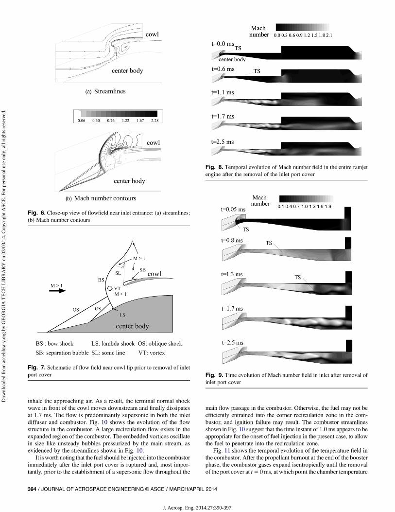
inhale the approaching air. As a result, the terminal normal shockwave in front of the cowl moves downstream and finally dissipatesat 1.7 ms. The flow is predominantly supersonic in both the inletdiffuser and combustor. Fig. 10 shows the evolution of the flowstructure in the combustor. A large recirculation flow exists in theexpanded region of the combustor. The embedded vortices oscillatein size like unsteady bubbles pressurized by the main stream, asevidenced by the streamlines shown in Fig. 10.
It isworth noting that the fuel should be injected into the combustorimmediately after the inlet port cover is ruptured and, most impor-tantly, prior to the establishment of a supersonic flow throughout the
main flow passage in the combustor. Otherwise, the fuel may not beefficiently entrained into the corner recirculation zone in the com-bustor, and ignition failure may result. The combustor streamlinesshown in Fig. 10 suggest that the time instant of 1.0 ms appears to beappropriate for the onset of fuel injection in the present case, to allowthe fuel to penetrate into the recirculation zone.
Fig. 11 shows the temporal evolution of the temperature field inthe combustor. After the propellant burnout at the end of the boosterphase, the combustor gases expand isentropically until the removalof the port cover at t5 0ms, at which point the chamber temperature
Fig. 6. Close-up view of flowfield near inlet entrance: (a) streamlines;(b) Mach number contours
Fig. 7. Schematic of flow field near cowl lip prior to removal of inletport cover
Fig. 8. Temporal evolution of Mach number field in the entire ramjetengine after the removal of the inlet port cover
Fig. 9. Time evolution of Mach number field in inlet after removal ofinlet port cover
394 / JOURNAL OF AEROSPACE ENGINEERING © ASCE / MARCH/APRIL 2014
J. Aerosp. Eng. 2014.27:390-397.
Dow
nloa
ded
from
asc
elib
rary
.org
by
GE
OR
GIA
TE
CH
LIB
RA
RY
on
03/0
3/14
. Cop
yrig
ht A
SCE
. For
per
sona
l use
onl
y; a
ll ri
ghts
res
erve
d.
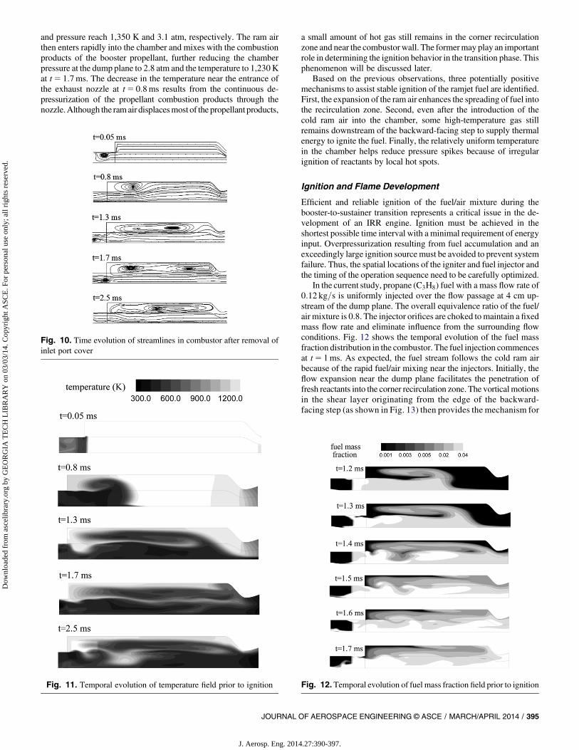
and pressure reach 1,350 K and 3.1 atm, respectively. The ram airthen enters rapidly into the chamber and mixes with the combustionproducts of the booster propellant, further reducing the chamberpressure at the dump plane to 2.8 atm and the temperature to 1,230Kat t5 1:7ms. The decrease in the temperature near the entrance ofthe exhaust nozzle at t5 0:8ms results from the continuous de-pressurization of the propellant combustion products through thenozzle.Although the ramair displacesmost of the propellant products,
a small amount of hot gas still remains in the corner recirculationzone and near the combustor wall. The formermay play an importantrole in determining the ignition behavior in the transition phase. Thisphenomenon will be discussed later.
Based on the previous observations, three potentially positivemechanisms to assist stable ignition of the ramjet fuel are identified.First, the expansion of the ram air enhances the spreading of fuel intothe recirculation zone. Second, even after the introduction of thecold ram air into the chamber, some high-temperature gas stillremains downstream of the backward-facing step to supply thermalenergy to ignite the fuel. Finally, the relatively uniform temperaturein the chamber helps reduce pressure spikes because of irregularignition of reactants by local hot spots.
Ignition and Flame Development
Efficient and reliable ignition of the fuel/air mixture during thebooster-to-sustainer transition represents a critical issue in the de-velopment of an IRR engine. Ignition must be achieved in theshortest possible time interval with a minimal requirement of energyinput. Overpressurization resulting from fuel accumulation and anexceedingly large ignition source must be avoided to prevent systemfailure. Thus, the spatial locations of the igniter and fuel injector andthe timing of the operation sequence need to be carefully optimized.
In the current study, propane (C3H8) fuel with a mass flow rate of0:12 kg=s is uniformly injected over the flow passage at 4 cm up-stream of the dump plane. The overall equivalence ratio of the fuel/air mixture is 0.8. The injector orifices are choked tomaintain a fixedmass flow rate and eliminate influence from the surrounding flowconditions. Fig. 12 shows the temporal evolution of the fuel massfraction distribution in the combustor. The fuel injection commencesat t5 1ms. As expected, the fuel stream follows the cold ram airbecause of the rapid fuel/air mixing near the injectors. Initially, theflow expansion near the dump plane facilitates the penetration offresh reactants into the corner recirculation zone. The vorticalmotionsin the shear layer originating from the edge of the backward-facing step (as shown in Fig. 13) then provides the mechanism for
Fig. 10. Time evolution of streamlines in combustor after removal ofinlet port cover
Fig. 11. Temporal evolution of temperature field prior to ignition Fig. 12. Temporal evolution of fuel mass fraction field prior to ignition
JOURNAL OF AEROSPACE ENGINEERING © ASCE / MARCH/APRIL 2014 / 395
J. Aerosp. Eng. 2014.27:390-397.
Dow
nloa
ded
from
asc
elib
rary
.org
by
GE
OR
GIA
TE
CH
LIB
RA
RY
on
03/0
3/14
. Cop
yrig
ht A
SCE
. For
per
sona
l use
onl
y; a
ll ri
ghts
res
erve
d.
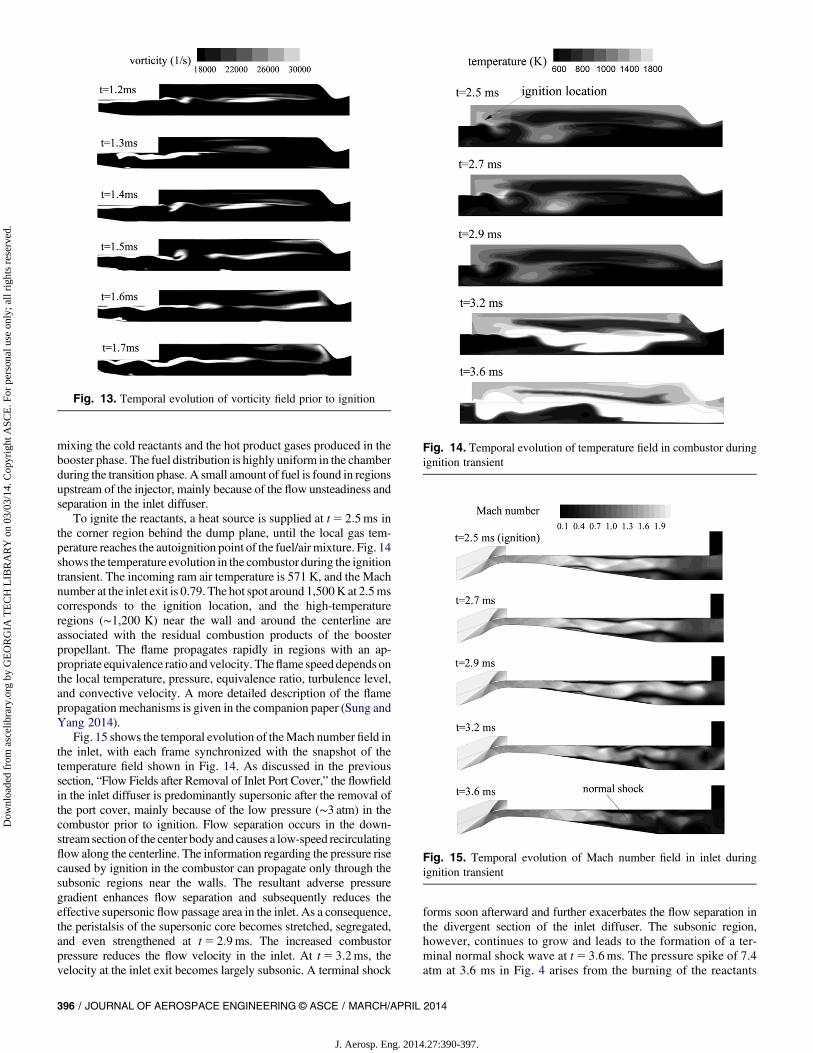
mixing the cold reactants and the hot product gases produced in thebooster phase. The fuel distribution is highly uniform in the chamberduring the transition phase. A small amount of fuel is found in regionsupstream of the injector, mainly because of the flow unsteadiness andseparation in the inlet diffuser.
To ignite the reactants, a heat source is supplied at t5 2:5ms inthe corner region behind the dump plane, until the local gas tem-perature reaches the autoignition point of the fuel/airmixture. Fig. 14shows the temperature evolution in the combustor during the ignitiontransient. The incoming ram air temperature is 571 K, and the Machnumber at the inlet exit is 0.79. The hot spot around 1,500K at 2.5mscorresponds to the ignition location, and the high-temperatureregions (∼1,200 K) near the wall and around the centerline areassociated with the residual combustion products of the boosterpropellant. The flame propagates rapidly in regions with an ap-propriate equivalence ratio and velocity. Theflame speed depends onthe local temperature, pressure, equivalence ratio, turbulence level,and convective velocity. A more detailed description of the flamepropagation mechanisms is given in the companion paper (Sung andYang 2014).
Fig. 15 shows the temporal evolution of theMach number field inthe inlet, with each frame synchronized with the snapshot of thetemperature field shown in Fig. 14. As discussed in the previoussection, “Flow Fields after Removal of Inlet Port Cover,” the flowfieldin the inlet diffuser is predominantly supersonic after the removal ofthe port cover, mainly because of the low pressure (∼3 atm) in thecombustor prior to ignition. Flow separation occurs in the down-stream section of the center body and causes a low-speed recirculatingflow along the centerline. The information regarding the pressure risecaused by ignition in the combustor can propagate only through thesubsonic regions near the walls. The resultant adverse pressuregradient enhances flow separation and subsequently reduces theeffective supersonic flow passage area in the inlet. As a consequence,the peristalsis of the supersonic core becomes stretched, segregated,and even strengthened at t5 2:9ms. The increased combustorpressure reduces the flow velocity in the inlet. At t5 3:2ms, thevelocity at the inlet exit becomes largely subsonic. A terminal shock
forms soon afterward and further exacerbates the flow separation inthe divergent section of the inlet diffuser. The subsonic region,however, continues to grow and leads to the formation of a ter-minal normal shock wave at t5 3:6ms. The pressure spike of 7.4atm at 3.6 ms in Fig. 4 arises from the burning of the reactants
Fig. 13. Temporal evolution of vorticity field prior to ignition
Fig. 14. Temporal evolution of temperature field in combustor duringignition transient
Fig. 15. Temporal evolution of Mach number field in inlet duringignition transient
396 / JOURNAL OF AEROSPACE ENGINEERING © ASCE / MARCH/APRIL 2014
J. Aerosp. Eng. 2014.27:390-397.
Dow
nloa
ded
from
asc
elib
rary
.org
by
GE
OR
GIA
TE
CH
LIB
RA
RY
on
03/0
3/14
. Cop
yrig
ht A
SCE
. For
per
sona
l use
onl
y; a
ll ri
ghts
res
erve
d.
accumulated in the chamber prior to the arrival of the flame. As theflame develops in the combustor, the chamber pressure increasesand eventually reaches its design condition of 5.5 atm for ramjetoperation.
Summary and Conclusions
The transition from the rocket booster to the ramjet sustainer phaseof an IRR engine was numerically investigated by treating theconservation equations for a multicomponent chemically reactingsystem. The model takes into account finite-rate chemical kineticsand uses a low-Reynolds-number k-ɛ turbulence scheme. Thecomputational geometry consists of the entire engine flowpath, fromthe freestream in front of the inlet through the exit of the exhaustnozzle.
The flowfields in the inlet diffuser and combustion chamber werefirst obtained with the port cover in place at the entrance of thecombustor. Immediately on the removal of the port cover, the ram airentered the combustor at a supersonic speed. Fuel injection andignition then followed. The ensuing flame establishment increasedthe chamber pressure to its design value for ramjet operation.Concurrently, the flowfield in the inlet diffuser started to settledown, and eventually a terminal normal shockwave formed andwassustained in the divergent section of the inlet diffuser. The operationtiming played an important role in achieving robust ignition andflame development.
References
Apte, S., and Yang, V. (2003). “A large eddy simulation study of transitionand flow instability in a porous-walled chamber with mass injections.”J. Fluid Mech., 447(2), 215–225.
Barber, T., Maicke, B., and Majdalani, J. (2009). “Current state of highspeed propulsion: Gaps, obstacles and technological challenges inhypersonic applications.”AIAAPaper 09-5118, 45th AIAA/ASME/SAE/ASEE Joint Propulsion Conf., American Institute of Aeronautics andAstronautics (AIAA), Reston, VA.
Bemdot, J. G., Heins, A. E., and Piercy, T. G. (1984). “Ramjet air inductionsystem for tactical missile application.” AGARD-LS-136, MarquardtCompany, Van Nuys, CA, 2.1–49.
Bogar, T. J., Sajben, M., and Kroutil, J. C. (1985). “Response of supersonicinlet to downstream perturbations.” J. Propul. Power, 1(2), 118–125.
Chakravarthy, S. R., and Osher, S. (1985). “A new class of high accuracyTVD schemes for hyperbolic conservation laws.” AIAA Paper 85-0363,23rd AIAA Aerospace Science Meeting, American Institute of Aero-nautics and Astronautics (AIAA), Reston, VA.
Fry, R. S. (2004). “A century of ramjet propulsion technology evolution.”J. Propul. Power, 20(1), 27–38.
Fung, Y. T., and Yang, Y. (1992). “Active control of nonlinear pressureoscillation in combustion chambers.” J. Propul. Power, 8(6), 1282–1289.
Fung, Y. T., Yang, Y., and Sinha, A. (1991). “Active control of combustioninstabilities with distributed actuators.”Combust. Sci. Technol., 78(4–6),217–245.
Hsieh, S., and Yang, V. (1997a). “A unified analysis of unsteady flowstructures in a supersonic ramjet engines.” AIAA Paper 97–0396, 35thAIAA Aerospace Science Meeting, American Institute of Aeronauticsand Astronautics (AIAA), Reston, VA.
Hsieh, S. Y., and Yang, V. (1997b). “A preconditioned flux-differencingscheme for chemically reacting flows at all mach numbers.” Int.J. Comput. Fluid Dyn., 8(1), 31–49.
Hsieh, T., Bogar, T. J., and Coakley, T. J. (1987). “Numerical simulationand comparisonwith experiment for self-excited oscillations in a diffuserflow.” AIAA J., 25(7), 936–943.
Lu, P., and Jain, L. (1998). “Numerical investigation of inlet buzz flow.”J. Propul. Power, 14(1), 90–100.
Matveev, K., and Culick, F. (2003). “A model for combustion instabilityinvolving vortex shedding.” Combust. Sci. Technol., 175(6), 1059–1083.
Menon, S., and Jou, W.-H. (1991). “Large-eddy simulations of combustioninstability in an axisymmetric ramjet combustor.”Combust. Sci. Technol.,75(1–3), 53–72.
Myers, T. D. (1984). “Integral boost, heat protection, port covers andtransition.” AGARD-LS-136, United Technologies Chemical SystemsDivision, San Jose, CA, 4.1–20.
Oh, J. Y., Ma, F., Hsieh, S. Y., and Yang, V. (2005). “Interactions betweenshock and acoustic waves in a supersonic inlet diffuser.” J. Propul.Power, 21(3), 486–495.
Ristori, A., Heid, G., Brossard, C., and Bresson, A. (2003). “Character-ization of the reacting two-phase flow inside a research ramjet com-bustor.” ONERA TP No. 2003-145, ONERA, Chatillon, France.
Roache, P. J. (1982). Computational fluid dynamics, Hermosa Publishers,Albuquerque, NM, 282–283.
Roh, T. S., Tseng, I. S., and Yang, V. (1995). “Effect of acoustic oscillationson flame dynamics of homogeneous propellants in rocket motors.”J. Propul. Power, 11(4), 640–650.
Sung, H.-G., and Yang, V. (2014). “Unified analysis of internal flowfield inan integrated rocket ramjet engine. II: Ramjet sustainer.” J. Aerosp. Eng.,10.1061/(ASCE)AS.1943-5525.0000256, 398–403.
Waltrup, P. J., White, M. E., and Gravlin, E. S. (2002). “History of U.S.Navy ramjet, scramjet, and mixed-cycle propulsion development.”J. Propul. Power, 18(1), 14–27.
Webster, F. F. (1989). “Ramjet development testing: Which way is right?”J. Propul. Power, 5(5), 565–576.
Westbrook, C. K., andDryer, F. L. (1981). “Simplified reactionmechanismsfor the oxidation of hydrocarbon fuels in flames.”Combust. Sci. Technol.,27(1–2), 31–43.
Yang, V., and Culick, F. E. C. (1985). “Analysis of unsteady invisciddiffuser flow with a shock wave.” J. Propul. Power, 1(3), 222–228.
Yang, V., and Culick, F. E. C. (1986). “Analysis of low frequency com-bustion instabilities in a laboratory ramjet combustor.” Combust. Sci.Technol., 45(1), 1–25.
Yang, Z., and Shih, T. H. (1993). “New time scale based k-ɛmodel for near-wall turbulence.” AIAA J., 31(7), 1191–1197.
Zarlingo, F. (1988). “Airbreathing propulsion concepts for high speedtacticalmissiles.”AIAAPaper 1988–3070, 24th AIAA/ASME/SAE/ASEEJoint Propulsion Conf., American Institute of Aeronautics and Astro-nautics (AIAA), Reston, VA.
JOURNAL OF AEROSPACE ENGINEERING © ASCE / MARCH/APRIL 2014 / 397
J. Aerosp. Eng. 2014.27:390-397.
Dow
nloa
ded
from
asc
elib
rary
.org
by
GE
OR
GIA
TE
CH
LIB
RA
RY
on
03/0
3/14
. Cop
yrig
ht A
SCE
. For
per
sona
l use
onl
y; a
ll ri
ghts
res
erve
d.