understanding the true meaning of precision - ibspe.com · understanding the true meaning of...
TRANSCRIPT
Understanding the true meaning of precision
Non-contact position and displacement measuring systems
Contents
05 Introduction and applications
06 Capacitive position and displacement measurement
08 Capacitive measuring systems overview
09 CPL490 Series
10 CPL190/CPL290 Series
12 CPL230/CPL350 Series
14 Capacitiveprobe dimensions
15 Eddy-current position and displacement measurement
16 Eddy-current position and displacement measuring systems overview
18 ECL202 Series
20 ECL150 Series
22 ECW110 Series
24 ECL101 Range
26 ECA101 System
28 Eddy-current probe dimensions
5
Introduction and applications
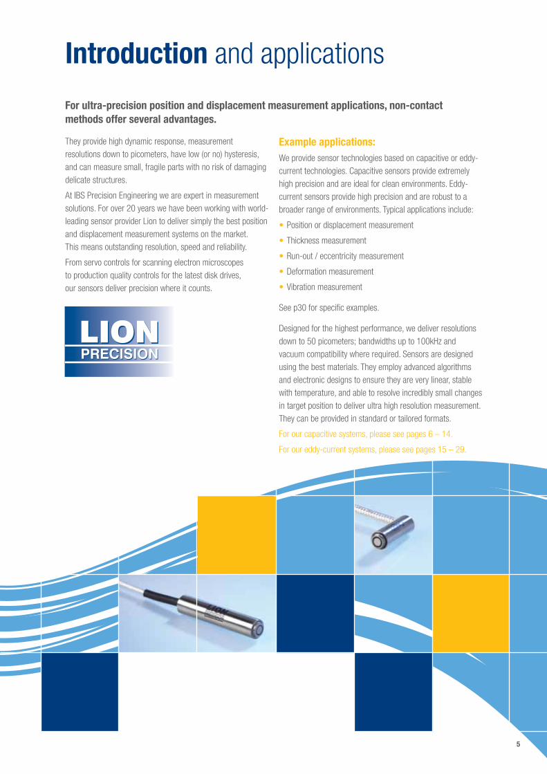
They provide high dynamic response, measurement resolutions down to picometers, have low (or no) hysteresis, and can measure small, fragile parts with no risk of damaging delicate structures.
At IBS Precision Engineering we are expert in measurement solutions. For over 20 years we have been working with world-leading sensor provider Lion to deliver simply the best position and displacement measurement systems on the market. This means outstanding resolution, speed and reliability.
From servo controls for scanning electron microscopes to production quality controls for the latest disk drives, our sensors deliver precision where it counts.
Example applications:We provide sensor technologies based on capacitive or eddy-current technologies. Capacitive sensors provide extremely high precision and are ideal for clean environments. Eddy-current sensors provide high precision and are robust to a broader range of environments. Typical applications include:
•Position or displacement measurement
•Thickness measurement
•Run-out / eccentricity measurement
•Deformation measurement
•Vibration measurement
See p30 for specific examples.
Designed for the highest performance, we deliver resolutions down to 50 picometers; bandwidths up to 100kHz and vacuum compatibility where required. Sensors are designed using the best materials. They employ advanced algorithms and electronic designs to ensure they are very linear, stable with temperature, and able to resolve incredibly small changes in target position to deliver ultra high resolution measurement. They can be provided in standard or tailored formats.
For our capacitive systems, please see pages 6 – 14.
For our eddy-current systems, please see pages 15 – 29.
For ultra-precision position and displacement measurement applications, non-contact methods offer several advantages.
6
Capacitive position and displacement measurement
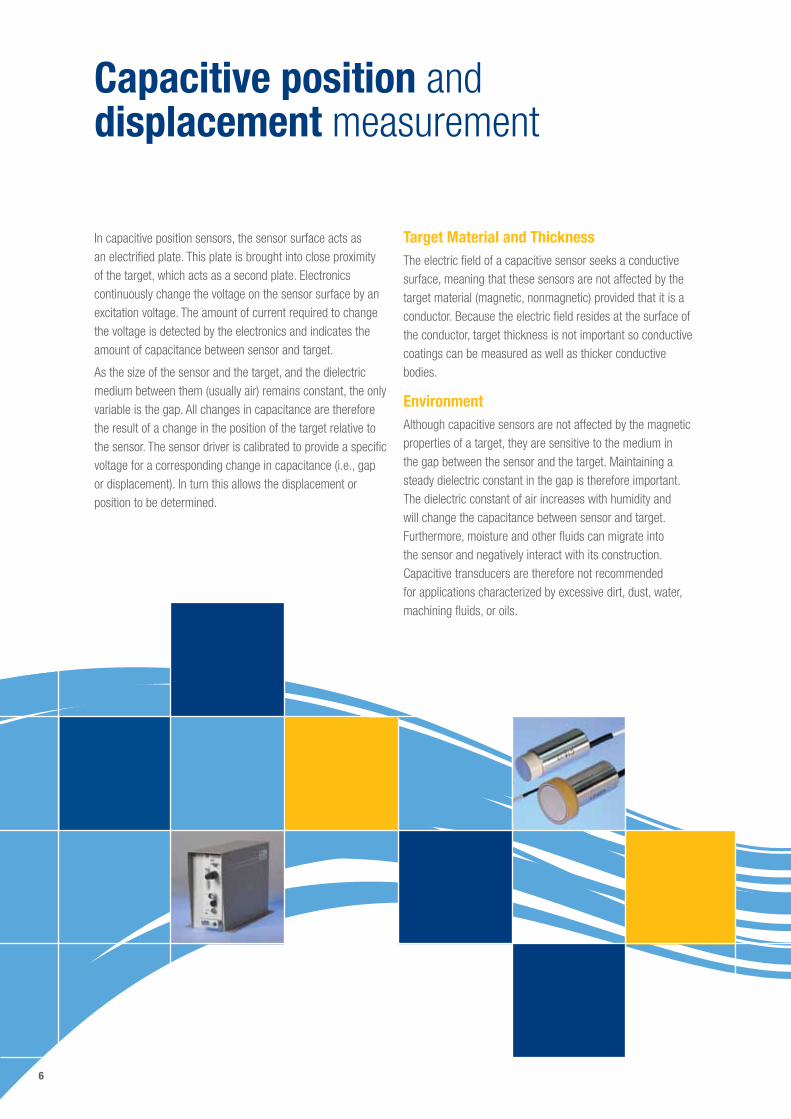
Target Material and ThicknessThe electric field of a capacitive sensor seeks a conductive surface, meaning that these sensors are not affected by the target material (magnetic, nonmagnetic) provided that it is a conductor. Because the electric field resides at the surface of the conductor, target thickness is not important so conductive coatings can be measured as well as thicker conductive bodies.
EnvironmentAlthough capacitive sensors are not affected by the magnetic properties of a target, they are sensitive to the medium in the gap between the sensor and the target. Maintaining a steady dielectric constant in the gap is therefore important. The dielectric constant of air increases with humidity and will change the capacitance between sensor and target. Furthermore, moisture and other fluids can migrate into the sensor and negatively interact with its construction. Capacitive transducers are therefore not recommended for applications characterized by excessive dirt, dust, water, machining fluids, or oils.
In capacitive position sensors, the sensor surface acts as an electrified plate. This plate is brought into close proximity of the target, which acts as a second plate. Electronics continuously change the voltage on the sensor surface by an excitation voltage. The amount of current required to change the voltage is detected by the electronics and indicates the amount of capacitance between sensor and target.
As the size of the sensor and the target, and the dielectric medium between them (usually air) remains constant, the only variable is the gap. All changes in capacitance are therefore the result of a change in the position of the target relative to the sensor. The sensor driver is calibrated to provide a specific voltage for a corresponding change in capacitance (i.e., gap or displacement). In turn this allows the displacement or position to be determined.
8
Capacitive measuring systems overview
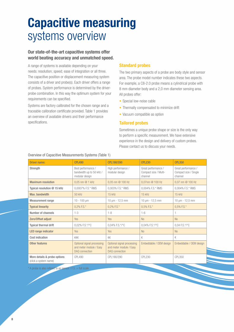
A range of systems is available depending on your needs: resolution; speed; ease of integration or all three. The capacitive position or displacement measuring system consists of a driver and probe(s). Each driver offers a range of probes. System performance is determined by the driver-probe combination. In this way the optimum system for your requirements can be specified.
Systems are factory calibrated for the chosen range and a traceable calibration certificate provided. Table 1 provides an overview of available drivers and their performance specifications.
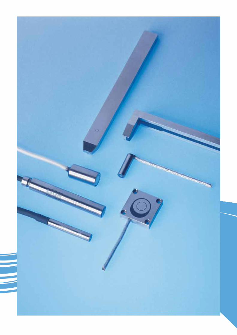
Standard probesThe two primary aspects of a probe are body style and sensor area. The probe model number indicates these two aspects. For example, a C8-2.0 probe means a cylindrical probe with 8 mm diameter body and a 2,0 mm diameter sensing area. All probes offer:
•Special low-noise cable
•Thermally compensated to minimize drift
•Vacuum compatible as option
Tailored probesSometimes a unique probe shape or size is the only way to perform a specific measurement. We have extensive experience in the design and delivery of custom probes. Please contact us to discuss your needs.
Overview of Capacitive Measurements Systems (Table 1)
Driver name: CPL490 CPL190/290 CPL230 CPL350
Strength Best performance / bandwidth up to 50 kHz / modular design
High performance / modular design
Great performance / Compact size / Multi-channel
Great performance / Compact size / Single channel
Maximum resolution 0,05 nm @ 1 kHz 0,05 nm @ 100 Hz 0,07nm @ 100 Hz 0,07 nm @ 100 Hz
Typical resolution @ 15 kHz 0,0007% F.S.* RMS 0,003% F.S.* RMS 0,004% F.S.* RMS 0,004% F.S.* RMS
Max. bandwidth 50 kHz 15 kHz 15 kHz 15 kHz
Measurement range 10 - 100 µm 10 µm - 12,5 mm 10 µm - 12,5 mm 10 µm - 12,5 mm
Typical linearity 0,2% F.S.* 0,2% F.S.* 0,5% F.S.* 0,5% F.S.*
Number of channels 1-3 1-8 1-6 1
Zero/Offset adjust Yes Yes No No
Typical thermal drift 0,02% F.S.*/°C 0,04% F.S.*/°C 0,04% F.S.*/°C 0,04 F.S.*/°C
LED range indicator Yes Yes No No
Cost indication €€€ €€ € €
Other features Optional signal processing and meter module / Easy DAQ connection
Optional signal processing and meter module / Easy DAQ connection
Embeddable / OEM design Embeddable / OEM design
More details & probe options (click a system name)
CPL490 CPL190/290 CPL230 CPL350
* A probe is also refered to as sensor / F.S. = full scale
Our state-of-the-art capacitive systems offer world beating accuracy and unmatched speed.
9
CPL490 Series
Ultimate Precision and Speed
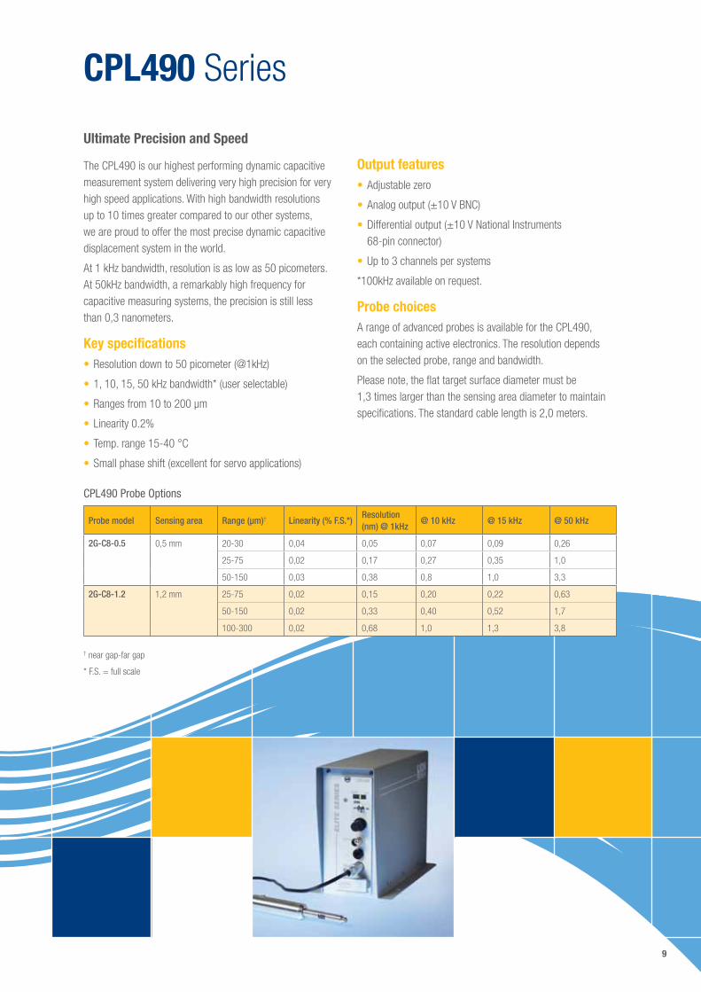
The CPL490 is our highest performing dynamic capacitive measurement system delivering very high precision for very high speed applications. With high bandwidth resolutions up to 10 times greater compared to our other systems, we are proud to offer the most precise dynamic capacitive displacement system in the world.
At 1 kHz bandwidth, resolution is as low as 50 picometers. At 50kHz bandwidth, a remarkably high frequency for capacitive measuring systems, the precision is still less than 0,3 nanometers.
Key specifications•Resolution down to 50 picometer (@1kHz)
•1, 10, 15, 50 kHz bandwidth* (user selectable)
•Ranges from 10 to 200 µm
•Linearity 0.2%
•Temp. range 15-40 °C
•Small phase shift (excellent for servo applications)
Output features•Adjustable zero
•Analog output (±10 V BNC)
•Differential output (±10 V National Instruments 68-pin connector)
•Up to 3 channels per systems
*100kHz available on request.
Probe choicesA range of advanced probes is available for the CPL490, each containing active electronics. The resolution depends on the selected probe, range and bandwidth.
Please note, the flat target surface diameter must be 1,3 times larger than the sensing area diameter to maintain specifications. The standard cable length is 2,0 meters.
CPL490 Probe Options
Probe model Sensing area Range (µm)† Linearity (% F.S.*)Resolution (nm) @ 1kHz
@ 10 kHz @ 15 kHz @ 50 kHz
2G-C8-0.5 0,5 mm 20-30 0,04 0,05 0,07 0,09 0,26
25-75 0,02 0,17 0,27 0,35 1,0
50-150 0,03 0,38 0,8 1,0 3,3
2G-C8-1.2 1,2 mm 25-75 0,02 0,15 0,20 0,22 0,63
50-150 0,02 0,33 0,40 0,52 1,7
100-300 0,02 0,68 1,0 1,3 3,8
† near gap-far gap
* F.S. = full scale
10
CPL190/CPL290 Series
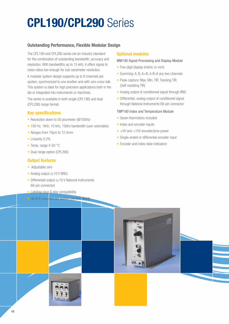
The CPL190 and CPL290 series set an industry standard for the combination of outstanding bandwidth, accuracy and resolution. With bandwidths up to 15 kHz, it offers signal to noise ratios low enough for sub nanometer resolution.
A modular system design supports up to 8 channels per system, synchronized to one another and with zero cross talk. This system is ideal for high precision applications both in the lab or integrated into instruments or machines.
The series is available in both single (CPL190) and dual (CPL290) range format.
Key specifications•Resolution down to 50 picometer (@100Hz)
•100 Hz, 1kHz, 10 kHz, 15kHz bandwidth (user selectable)
•Ranges from 10µm to 12.5mm
•Linearity 0.2%
•Temp. range 4-50 °C
•Dual range option (CPL290)
Output features• Adjustable zero
•Analog output (±10 V BNC)
•Differential output (±10 V National Instruments 68-pin connector)
•LabView plug & play compatibility
•Up to 8 channels per system (synchronized)
Outstanding Performance, Flexible Modular Design
Optional modulesMM190 Signal Processing and Display Module
•Five-digit display (metric or inch)
•Summing: A, B, A+B, A-B of any two channels
•Peak-capture: Max, Min, TIR, Tracking TIR (Self-resetting TIR)
•Analog output of conditioned signal through BNC
•Differential, analog output of conditioned signal through National Instruments 68-pin connector
TMP190 Index and Temperature Module
•Seven thermistors included
• Index and encoder inputs
•+5V and +15V encoder/prox power
•Single-ended or differential encoder input
•Encoder and index state indicators
11
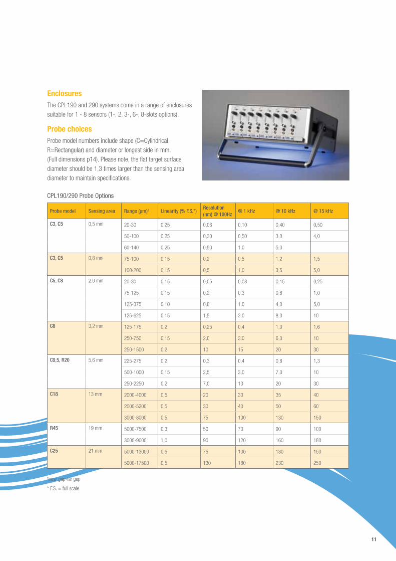
EnclosuresThe CPL190 and 290 systems come in a range of enclosures suitable for 1 - 8 sensors (1-, 2, 3-, 6-, 8-slots options).
Probe choicesProbe model numbers include shape (C=Cylindrical, R=Rectangular) and diameter or longest side in mm. (Full dimensions p14). Please note, the flat target surface diameter should be 1,3 times larger than the sensing area diameter to maintain specifications.
CPL190/290 Probe Options
Probe model Sensing area Range (µm)† Linearity (% F.S.*)Resolution (nm) @ 100Hz
@ 1 kHz @ 10 kHz @ 15 kHz
C3, C5 0,5 mm 20-30 0,25 0,06 0,10 0,40 0,50
50-100 0,25 0,30 0,50 3,0 4,0
60-140 0,25 0,50 1,0 5,0
C3, C5
0,8 mm
75-100 0,15 0,2 0,5 1,2 1,5
100-200 0,15 0,5 1,0 3,5 5,0
C5, C8
2,0 mm 20-30 0,15 0,05 0,08 0,15 0,25
75-125 0,15 0,2 0,3 0,6 1,0
125-375 0,10 0,8 1,0 4,0 5,0
125-625 0,15 1,5 3,0 8,0 10
C8 3,2 mm 125-175 0,2 0,25 0,4 1,0 1,6
250-750 0,15 2,0 3,0 6,0 10
250-1500 0,2 10 15 20 30
C9,5, R20 5,6 mm 225-275 0,2 0,3 0,4 0,8 1,3
500-1000 0,15 2,5 3,0 7,0 10
250-2250 0,2 7,0 10 20 30
C18 13 mm
2000-4000 0,5 20 30 35 40
2000-5200 0,5 30 40 50 60
3000-8000 0,5 75 100 130 150
R45 19 mm 5000-7500 0,3 50 70 90 100
3000-9000 1,0 90 120 160 180
C25 21 mm 5000-13000 0,5 75 100 130 150
5000-17500 0,5 130 180 230 250
†near gap-far gap
* F.S. = full scale
12
CPL230/CPL350 Series
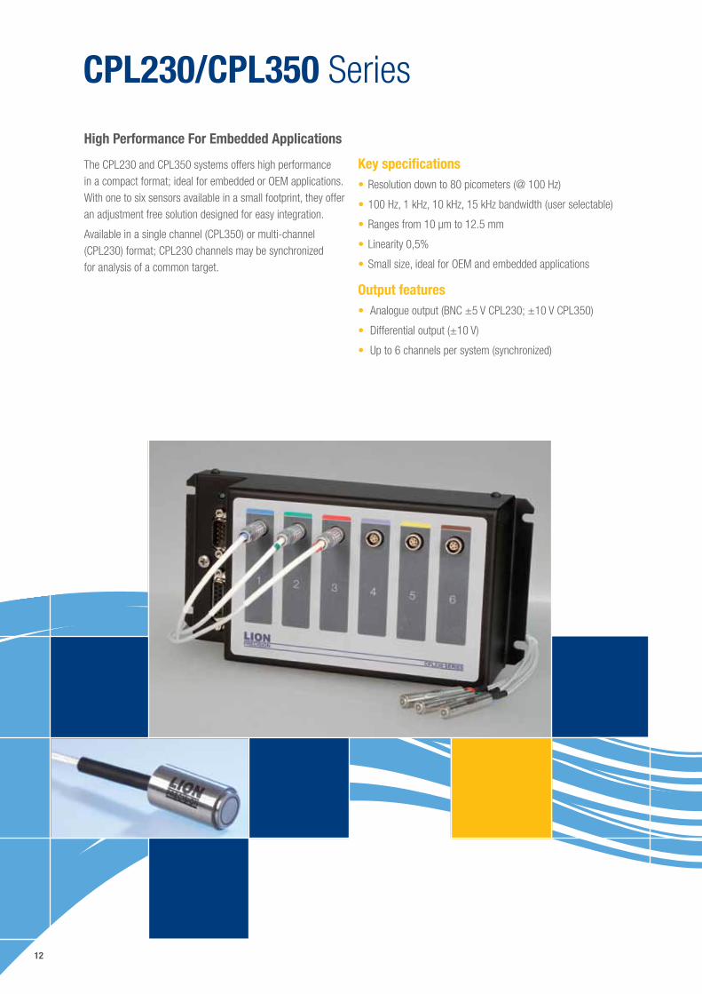
The CPL230 and CPL350 systems offers high performance in a compact format; ideal for embedded or OEM applications. With one to six sensors available in a small footprint, they offer an adjustment free solution designed for easy integration.
Available in a single channel (CPL350) or multi-channel (CPL230) format; CPL230 channels may be synchronized for analysis of a common target.
High Performance For Embedded Applications
Key specifications•Resolution down to 80 picometers (@ 100 Hz)
•100 Hz, 1 kHz, 10 kHz, 15 kHz bandwidth (user selectable)
•Ranges from 10 µm to 12.5 mm
•Linearity 0,5%
•Small size, ideal for OEM and embedded applications
Output features• Analogue output (BNC ±5 V CPL230; ±10 V CPL350)
• Differential output (±10 V)
• Up to 6 channels per system (synchronized)
13
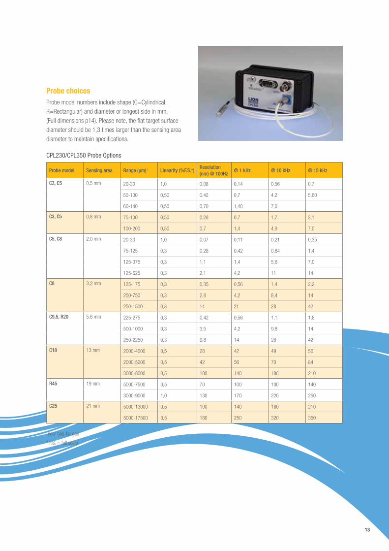
Probe choicesProbe model numbers include shape (C=Cylindrical, R=Rectangular) and diameter or longest side in mm. (Full dimensions p14). Please note, the flat target surface diameter should be 1,3 times larger than the sensing area diameter to maintain specifications.
CPL230/CPL350 Probe Options
Probe model Sensing area Range (µm)† Linearity (%F.S.*)Resolution (nm) @ 100Hz
@ 1 kHz @ 10 kHz @ 15 kHz
C3, C5
0,5 mm 20-30 1,0 0,08 0,14 0,56 0,7
50-100 0,50 0,42 0,7 4,2 5,60
60-140 0,50 0,70 1,40 7,0
C3, C5
0,8 mm
75-100 0,50 0,28 0,7 1,7 2,1
100-200 0,50 0,7 1,4 4,9 7,0
C5, C8 2,0 mm 20-30 1,0 0,07 0,11 0,21 0,35
75-125 0,3 0,28 0,42 0,84 1,4
125-375 0,3 1,1 1,4 5,6 7,0
125-625 0,3 2,1 4,2 11 14
C8 3,2 mm
125-175 0,3 0,35 0,56 1,4 2,2
250-750 0,3 2,8 4,2 8,4 14
250-1500 0,3 14 21 28 42
C9,5, R20 5,6 mm 225-275 0,3 0,42 0,56 1,1 1,8
500-1000 0,3 3,5 4,2 9,8 14
250-2250 0,3 9,8 14 28 42
C18 13 mm 2000-4000 0,5 28 42 49 56
2000-5200 0,5 42 56 70 84
3000-8000 0,5 100 140 180 210
R45 19 mm 5000-7500 0,5 70 100 100 140
3000-9000 1,0 130 170 220 250
C25 21 mm 5000-13000 0,5 100 140 180 210
5000-17500 0,5 180 250 320 350
†near gap-far gap
* F.S. = full scale
14
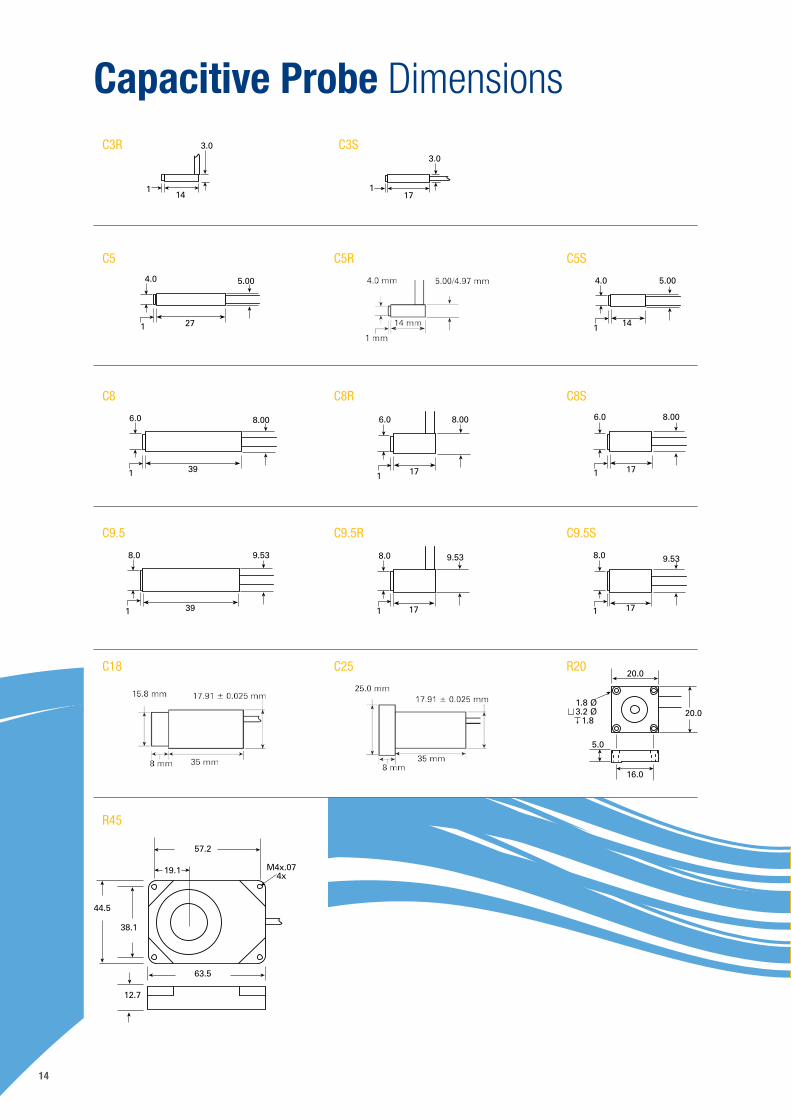
Capacitive Probe Dimensions
16.0
5.0
20.0
20.01.8 Ø3.2 Ø
1.8
57.2
19.1 M4x.07 4x
38.1
44.5
63.5
12.7
3.0
141
3.0
171
27
5.00
1
4.0
14
5.00
1
4.0
39
8.00
1
6.0
17
8.00
1
6.0
17
8.00
1
6.0
39
9.53
1
8.0
17
9.53
1
8.0
17
9.53
1
8.0
C3R
C5
C8
C9.5
C18
R45
C5R
C8R
C9.5R
C25
C5S
C8S
C9.5S
R20
C3S
15
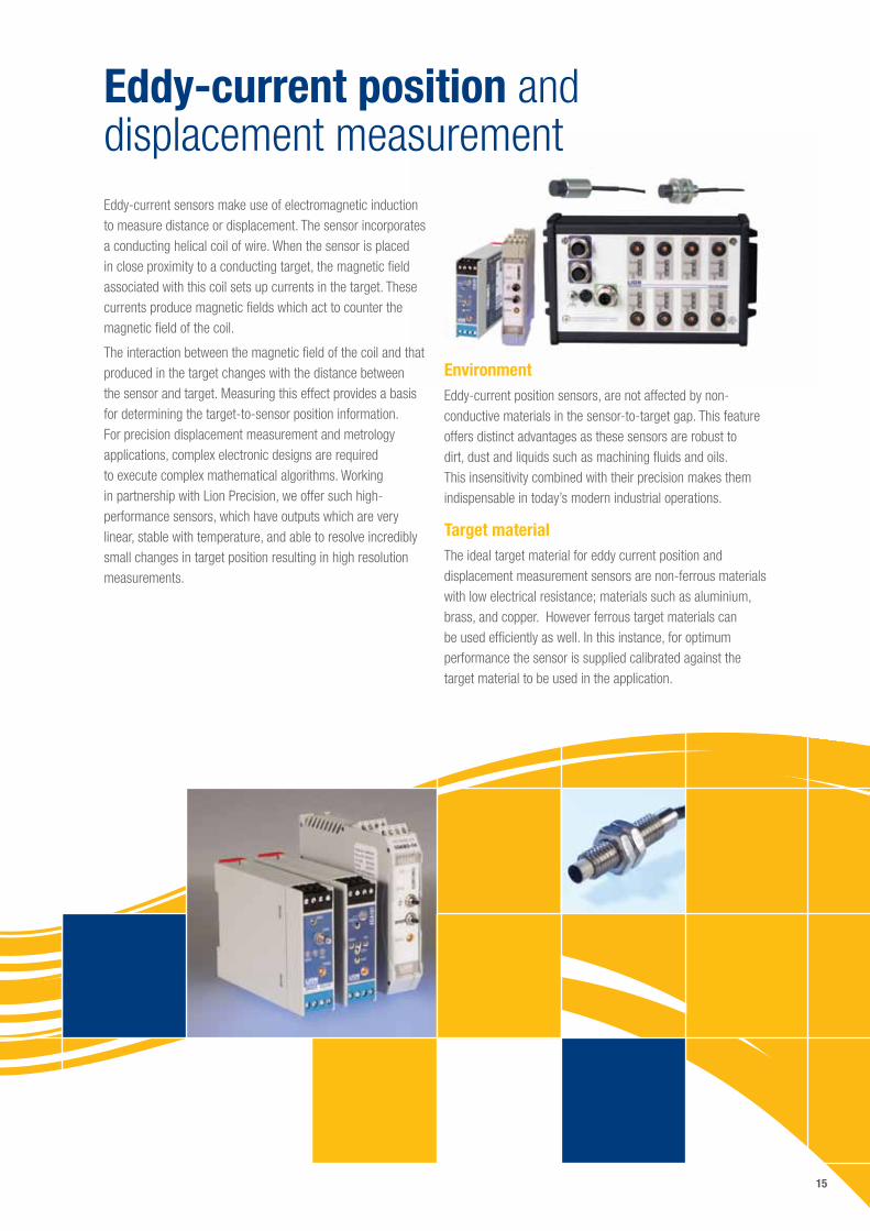
Eddy-current position and displacement measurementEddy-current sensors make use of electromagnetic induction to measure distance or displacement. The sensor incorporates a conducting helical coil of wire. When the sensor is placed in close proximity to a conducting target, the magnetic field associated with this coil sets up currents in the target. These currents produce magnetic fields which act to counter the magnetic field of the coil.
The interaction between the magnetic field of the coil and that produced in the target changes with the distance between the sensor and target. Measuring this effect provides a basis for determining the target-to-sensor position information. For precision displacement measurement and metrology applications, complex electronic designs are required to execute complex mathematical algorithms. Working in partnership with Lion Precision, we offer such high-performance sensors, which have outputs which are very linear, stable with temperature, and able to resolve incredibly small changes in target position resulting in high resolution measurements.
Environment Eddy-current position sensors, are not affected by non-conductive materials in the sensor-to-target gap. This feature offers distinct advantages as these sensors are robust to dirt, dust and liquids such as machining fluids and oils. This insensitivity combined with their precision makes them indispensable in today’s modern industrial operations.
Target materialThe ideal target material for eddy current position and displacement measurement sensors are non-ferrous materials with low electrical resistance; materials such as aluminium, brass, and copper. However ferrous target materials can be used efficiently as well. In this instance, for optimum performance the sensor is supplied calibrated against the target material to be used in the application.
16
Eddy-current position and displacement measuring systems overviewFor precision displacement, position measurement or metrology applications in environments involving liquids, dirt or other contaminants our high performance Eddy current measuring systems provide an outstanding solution. Low noise and very high speed are just some of the advantages.
The system consists of a driver and probe that, together with the calibration, determine the performance specifications. Table 2 provides an overview of available drivers and related performance. Further details, including the probes available for each driver is described in the following pages.
Systems are factory calibrated for the chosen range and material. A traceable calibration certificate is provided.
Critical specifications•Nanometer resolution
•High bandwidth (up to 80 kHz)
•Low noise
•Great linearity
•Low temperature coefficient
• Insensitive to humidity and environmental contamination
•Vacuum compatible as option
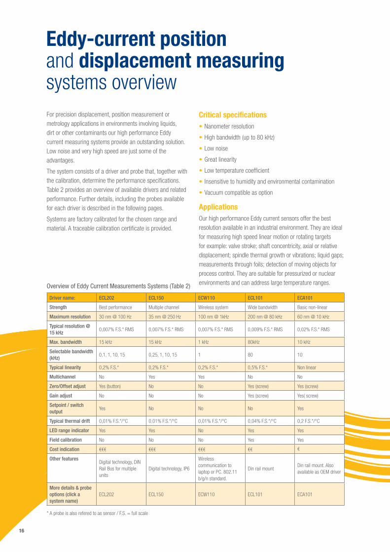
ApplicationsOur high performance Eddy current sensors offer the best resolution available in an industrial environment. They are ideal for measuring high speed linear motion or rotating targets for example: valve stroke; shaft concentricity, axial or relative displacement; spindle thermal growth or vibrations; liquid gaps; measurements through foils; detection of moving objects for process control. They are suitable for pressurized or nuclear environments and can address large temperature ranges.Overview of Eddy Current Measurements Systems (Table 2)
Driver name: ECL202 ECL150 ECW110 ECL101 ECA101
Strength Best performance Multiple channel Wireless system Wide bandwidth Basic non-linear
Maximum resolution 30 nm @ 100 Hz 35 nm @ 250 Hz 100 nm @ 1kHz 200 nm @ 80 kHz 60 nm @ 10 kHz
Typical resolution @ 15 kHz
0,007% F.S.* RMS 0,007% F.S.* RMS 0,007% F.S.* RMS 0,009% F.S.* RMS 0,02% F.S.* RMS
Max. bandwidth 15 kHz 15 kHz 1 kHz 80kHz 10 kHz
Selectable bandwidth (kHz)
0,1, 1, 10, 15 0,25, 1, 10, 15 1 80 10
Typical linearity 0,2% F.S.* 0,2% F.S.* 0,2% F.S.* 0,5% F.S.* Non linear
Multichannel No Yes Yes No No
Zero/Offset adjust Yes (button) No No Yes (screw) Yes (screw)
Gain adjust No No No Yes (screw) Yes( screw)
Setpoint / switch output
Yes No No No Yes
Typical thermal drift 0,01% F.S.*/°C 0,01% F.S.*/°C 0,01% F.S.*/°C 0,04% F.S.*/°C 0,2 F.S.*/°C
LED range indicator Yes Yes No Yes Yes
Field calibration No No No Yes Yes
Cost indication €€€ €€€ €€€ €€ €
Other features Digital technology, DIN Rail Bus for multiple units
Digital technology, IP6
Wireless communication to laptop or PC. 802.11 b/g/n standard.
Din rail mountDin rail mount. Also available as OEM driver
More details & probe options (click a system name)
ECL202 ECL150 ECW110 ECL101 ECA101
* A probe is also refered to as sensor / F.S. = full scale
18
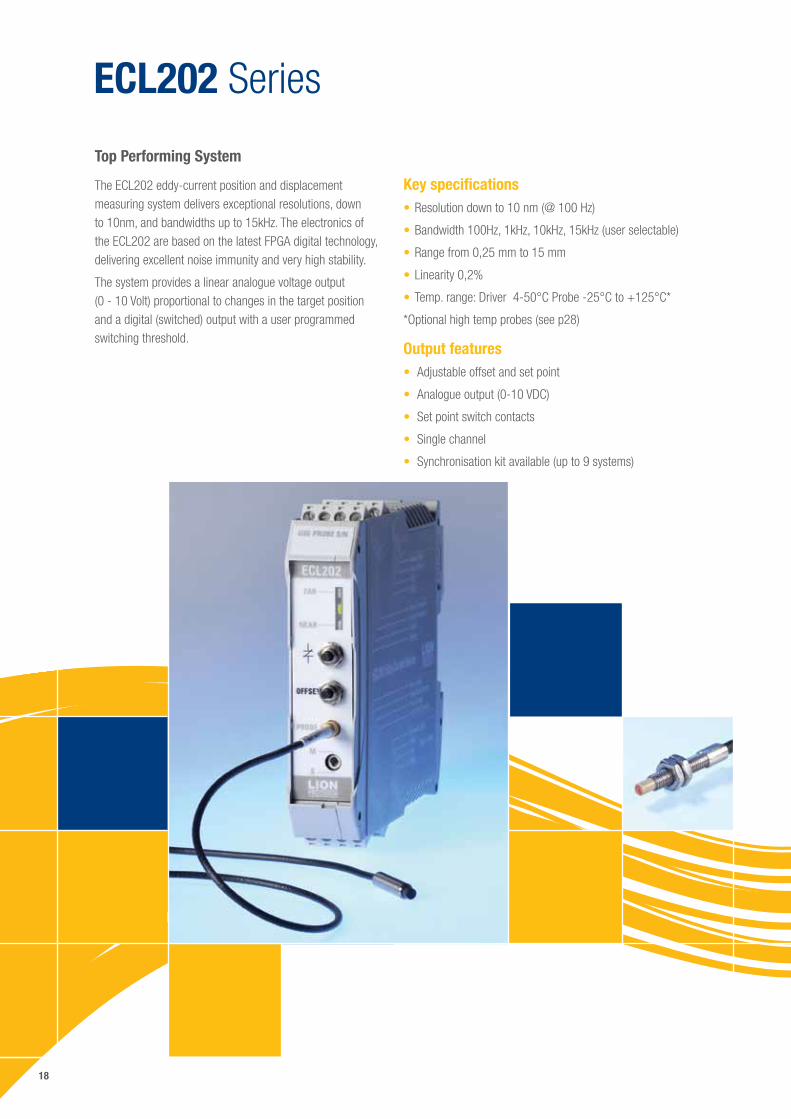
ECL202 Series
The ECL202 eddy-current position and displacement measuring system delivers exceptional resolutions, down to 10nm, and bandwidths up to 15kHz. The electronics of the ECL202 are based on the latest FPGA digital technology, delivering excellent noise immunity and very high stability.
The system provides a linear analogue voltage output (0 - 10 Volt) proportional to changes in the target position and a digital (switched) output with a user programmed switching threshold.
Top Performing System
Key specifications•Resolution down to 10 nm (@ 100 Hz)
•Bandwidth 100Hz, 1kHz, 10kHz, 15kHz (user selectable)
•Range from 0,25 mm to 15 mm
•Linearity 0,2%
•Temp. range: Driver 4-50°C Probe -25°C to +125°C*
*Optional high temp probes (see p28)
Output features• Adjustable offset and set point
• Analogue output (0-10 VDC)
• Set point switch contacts
• Single channel
• Synchronisation kit available (up to 9 systems)
19
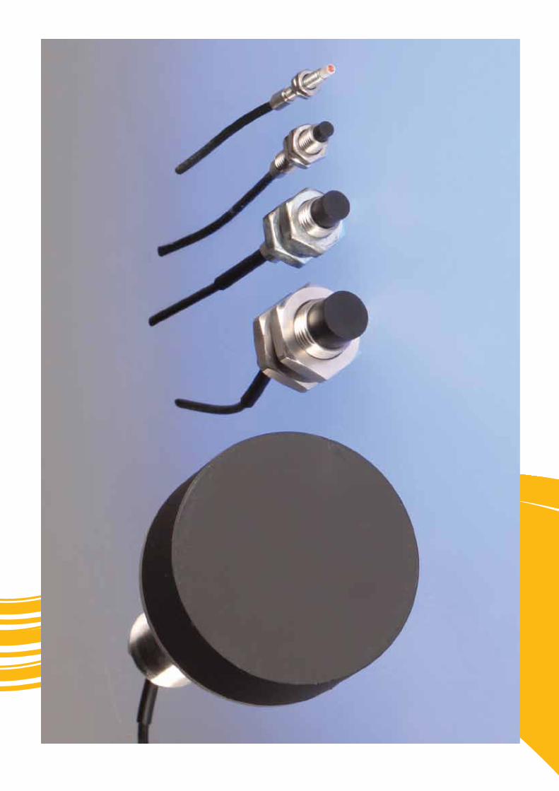
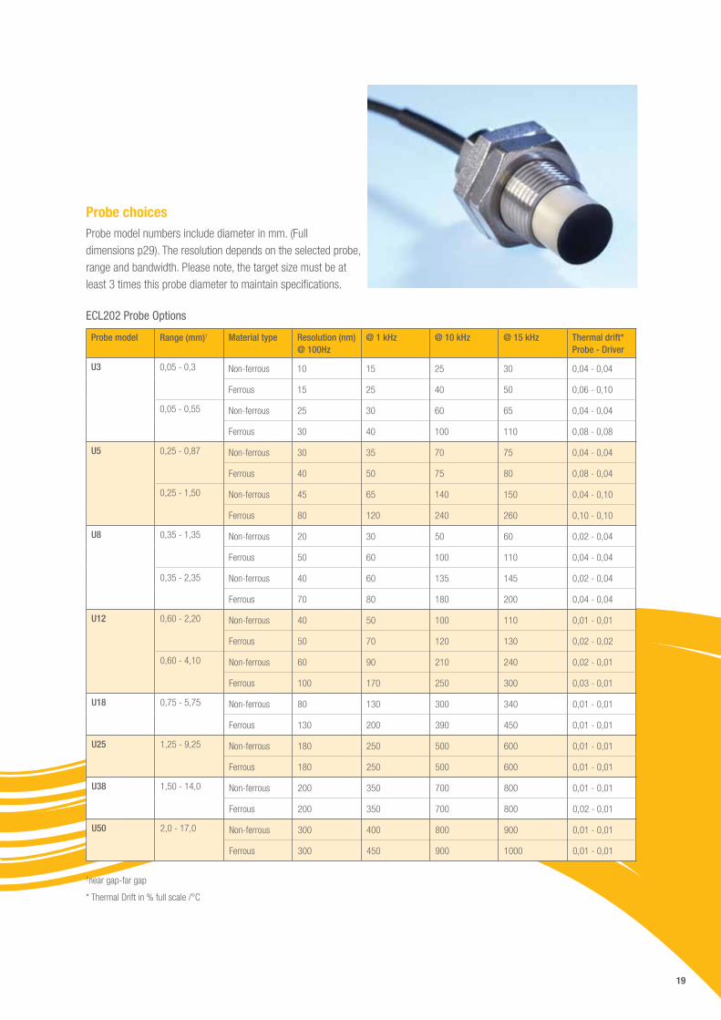
Probe choicesProbe model numbers include diameter in mm. (Full dimensions p29). The resolution depends on the selected probe, range and bandwidth. Please note, the target size must be at least 3 times this probe diameter to maintain specifications.
ECL202 Probe Options
Probe model Range (mm)† Material type Resolution (nm) @ 100Hz
@ 1 kHz @ 10 kHz @ 15 kHz Thermal drift* Probe - Driver
U3
0,05 - 0,3
Non-ferrous 10 15 25 30 0,04 - 0,04
Ferrous 15 25 40 50 0,06 - 0,10
0,05 - 0,55
Non-ferrous 25 30 60 65 0,04 - 0,04
Ferrous 30 40 100 110 0,08 - 0,08
U5
0,25 - 0,87
Non-ferrous 30 35 70 75 0,04 - 0,04
Ferrous 40 50 75 80 0,08 - 0,04
0,25 - 1,50
Non-ferrous 45 65 140 150 0,04 - 0,10
Ferrous 80 120 240 260 0,10 - 0,10
U8 0,35 - 1,35
Non-ferrous 20 30 50 60 0,02 - 0,04
Ferrous 50 60 100 110 0,04 - 0,04
0,35 - 2,35
Non-ferrous 40 60 135 145 0,02 - 0,04
Ferrous 70 80 180 200 0,04 - 0,04
U12 0,60 - 2,20
Non-ferrous 40 50 100 110 0,01 - 0,01
Ferrous 50 70 120 130 0,02 - 0,02
0,60 - 4,10
Non-ferrous 60 90 210 240 0,02 - 0,01
Ferrous 100 170 250 300 0,03 - 0,01
U18
0,75 - 5,75
Non-ferrous 80 130 300 340 0,01 - 0,01
Ferrous 130 200 390 450 0,01 - 0,01
U25
1,25 - 9,25
Non-ferrous 180 250 500 600 0,01 - 0,01
Ferrous 180 250 500 600 0,01 - 0,01
U38
1,50 - 14,0
Non-ferrous 200 350 700 800 0,01 - 0,01
Ferrous 200 350 700 800 0,02 - 0,01
U50
2,0 - 17,0
Non-ferrous 300 400 800 900 0,01 - 0,01
Ferrous 300 450 900 1000 0,01 - 0,01
†near gap-far gap
* Thermal Drift in % full scale /°C
20
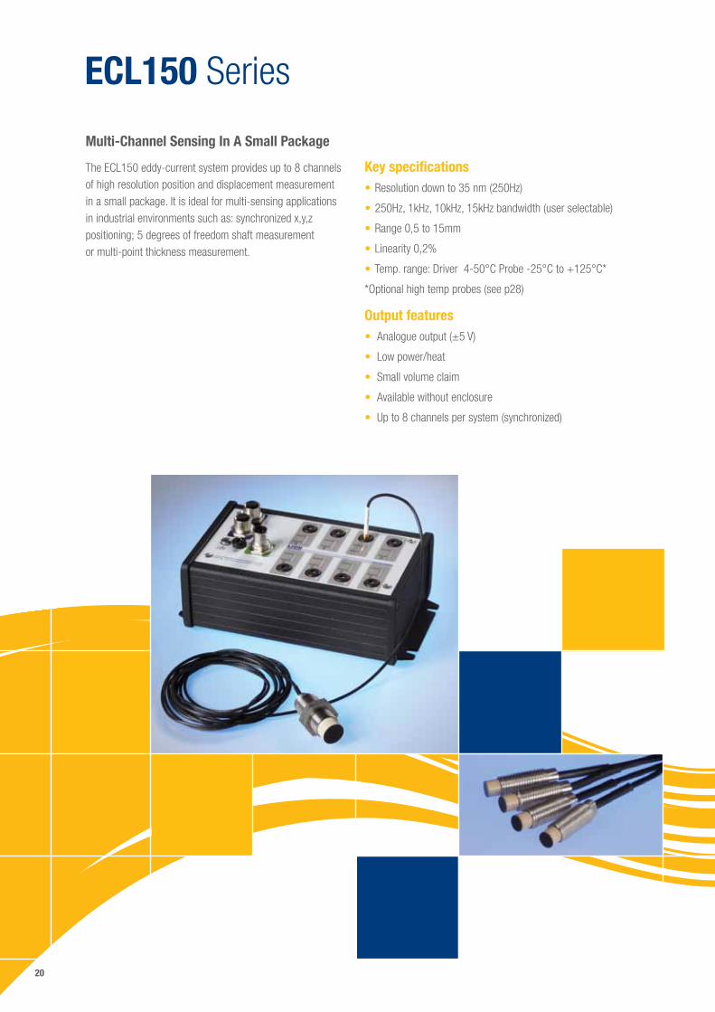
ECL150 Series
The ECL150 eddy-current system provides up to 8 channels of high resolution position and displacement measurement in a small package. It is ideal for multi-sensing applications in industrial environments such as: synchronized x,y,z positioning; 5 degrees of freedom shaft measurement or multi-point thickness measurement.
Multi-Channel Sensing In A Small Package
Key specifications•Resolution down to 35 nm (250Hz)
•250Hz, 1kHz, 10kHz, 15kHz bandwidth (user selectable)
•Range 0,5 to 15mm
•Linearity 0,2%
•Temp. range: Driver 4-50°C Probe -25°C to +125°C*
*Optional high temp probes (see p28)
Output features• Analogue output (±5 V)
• Low power/heat
• Small volume claim
• Available without enclosure
• Up to 8 channels per system (synchronized)
21
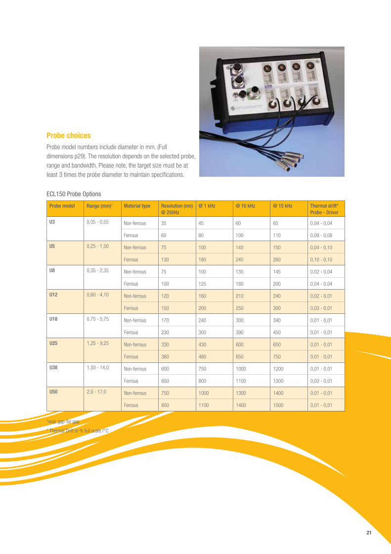
Probe choicesProbe model numbers include diameter in mm. (Full dimensions p29). The resolution depends on the selected probe, range and bandwidth. Please note, the target size must be at least 3 times the probe diameter to maintain specifications.
ECL150 Probe Options
Probe model Range (mm)† Material type Resolution (nm) @ 250Hz
@ 1 kHz @ 10 kHz @ 15 kHz Thermal drift* Probe - Driver
U3
0,05 - 0,55
Non-ferrous 35 45 60 65 0,04 - 0,04
Ferrous 60 80 100 110 0,08 - 0,08
U5
0,25 - 1,50
Non-ferrous 75 100 140 150 0,04 - 0,10
Ferrous 130 180 240 260 0,10 - 0,10
U8
0,35 - 2,35
Non-ferrous 75 100 135 145 0,02 - 0,04
Ferrous 100 125 180 200 0,04 - 0,04
U12
0,60 - 4,10
Non-ferrous 120 160 210 240 0,02 - 0,01
Ferrous 150 200 250 300 0,03 - 0,01
U18
0,75 - 5,75
Non-ferrous 170 240 300 340 0,01 - 0,01
Ferrous 230 300 390 450 0,01 - 0,01
U25
1,25 - 9,25
Non-ferrous 330 430 600 650 0,01 - 0,01
Ferrous 360 480 650 750 0,01 - 0,01
U38
1,50 - 14,0
Non-ferrous 600 750 1000 1200 0,01 - 0,01
Ferrous 650 800 1100 1300 0,02 - 0,01
U50
2,0 - 17,0
Non-ferrous 750 1000 1300 1400 0,01 - 0,01
Ferrous 800 1100 1400 1500 0,01 - 0,01
†near gap-far gap
* Thermal Drift in % full scale /°C
22
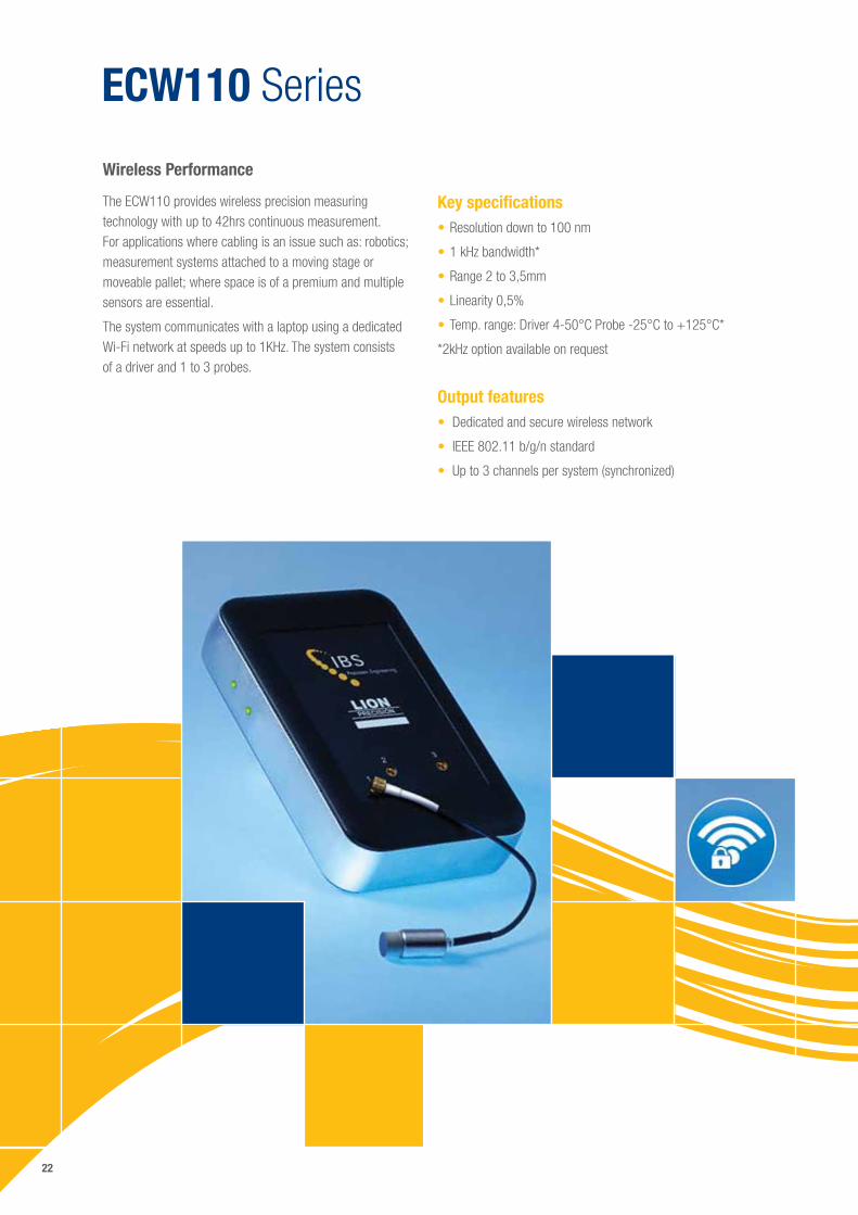
ECW110 Series
The ECW110 provides wireless precision measuring technology with up to 42hrs continuous measurement. For applications where cabling is an issue such as: robotics; measurement systems attached to a moving stage or moveable pallet; where space is of a premium and multiple sensors are essential.
The system communicates with a laptop using a dedicated Wi-Fi network at speeds up to 1KHz. The system consists of a driver and 1 to 3 probes.
Wireless Performance
Key specifications•Resolution down to 100 nm
•1 kHz bandwidth*
•Range 2 to 3,5mm
•Linearity 0,5%
•Temp. range: Driver 4-50°C Probe -25°C to +125°C*
*2kHz option available on request
Output features• Dedicated and secure wireless network
• IEEE 802.11 b/g/n standard
• Up to 3 channels per system (synchronized)
23
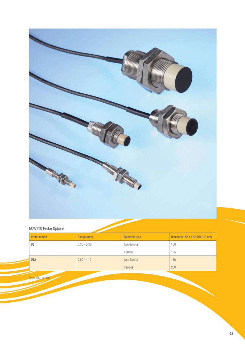
ECW110 Probe Options
Probe model Range (mm)† Material type Resolution @ 1 kHz (RMS in nm)
U8
0,35 - 2,35
Non-ferrous 100
Ferrous 125
U12
0,60 - 4,10
Non-ferrous 160
Ferrous 200
†near gap-far gap
24
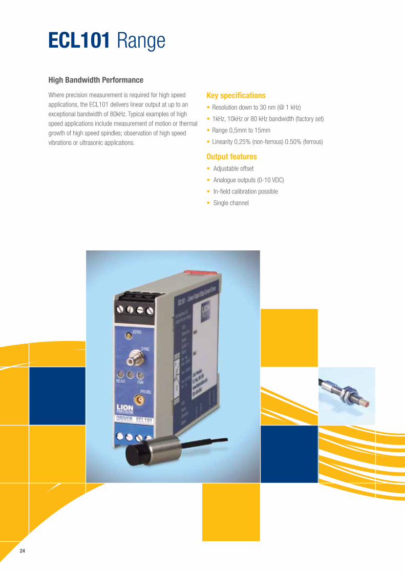
ECL101 Range
Where precision measurement is required for high speed applications, the ECL101 delivers linear output at up to an exceptional bandwidth of 80kHz. Typical examples of high speed applications include measurement of motion or thermal growth of high speed spindles; observation of high speed vibrations or ultrasonic applications.
High Bandwidth Performance
Key specifications•Resolution down to 30 nm (@ 1 kHz)
•1kHz, 10kHz or 80 kHz bandwidth (factory set)
•Range 0,5mm to 15mm
•Linearity 0,25% (non-ferrous) 0.50% (ferrous)
Output features• Adjustable offset
• Analogue outputs (0-10 VDC)
• In-field calibration possible
• Single channel
25
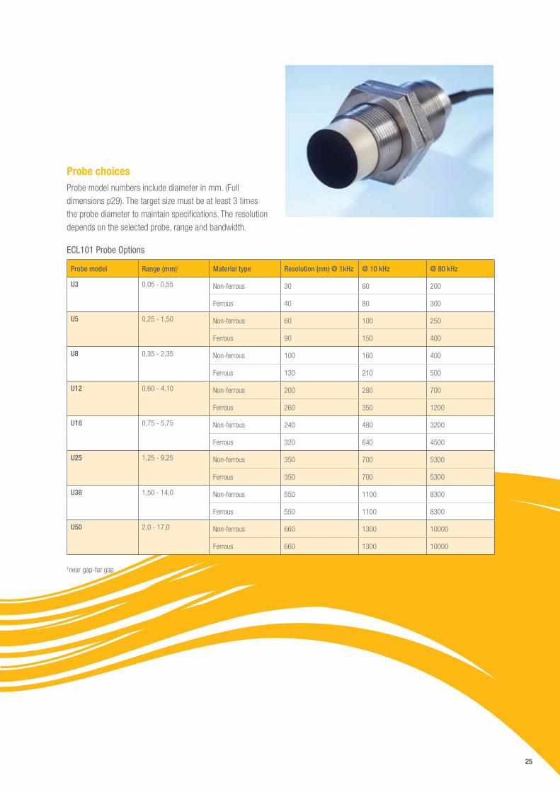
Probe choicesProbe model numbers include diameter in mm. (Full dimensions p29). The target size must be at least 3 times the probe diameter to maintain specifications. The resolution depends on the selected probe, range and bandwidth.
ECL101 Probe Options
Probe model Range (mm)† Material type Resolution (nm) @ 1kHz @ 10 kHz @ 80 kHz
U3
0,05 - 0,55
Non-ferrous 30 60 200
Ferrous 40 80 300
U5
0,25 - 1,50
Non-ferrous 60 100 250
Ferrous 90 150 400
U8
0,35 - 2,35
Non-ferrous 100 160 400
Ferrous 130 210 500
U12
0,60 - 4,10
Non-ferrous 200 280 700
Ferrous 260 350 1200
U18
0,75 - 5,75
Non-ferrous 240 480 3200
Ferrous 320 640 4500
U25
1,25 - 9,25
Non-ferrous 350 700 5300
Ferrous 350 700 5300
U38
1,50 - 14,0
Non-ferrous 550 1100 8300
Ferrous 550 1100 8300
U50
2,0 - 17,0
Non-ferrous 660 1300 10000
Ferrous 660 1300 10000
†near gap-far gap
26
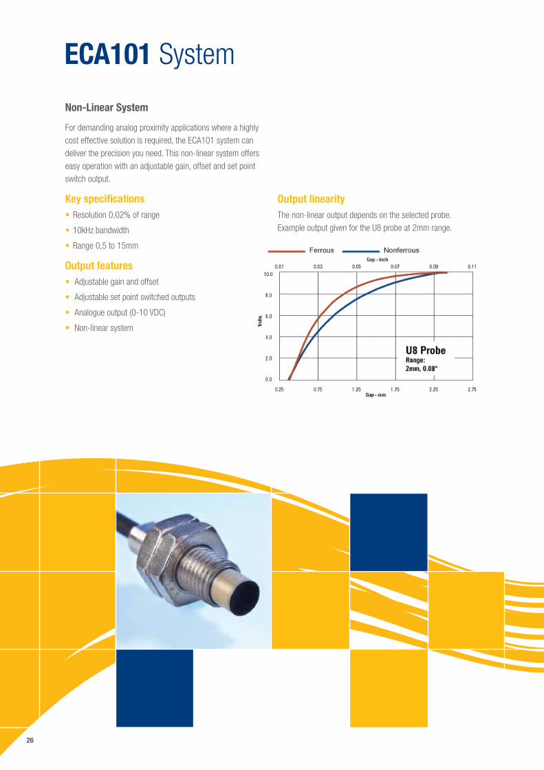
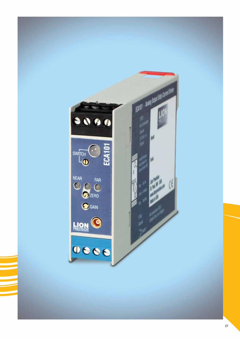
ECA101 System
For demanding analog proximity applications where a highly cost effective solution is required, the ECA101 system can deliver the precision you need. This non-linear system offers easy operation with an adjustable gain, offset and set point switch output.
Key specifications•Resolution 0,02% of range
•10kHz bandwidth
•Range 0,5 to 15mm
Output features• Adjustable gain and offset
• Adjustable set point switched outputs
• Analogue output (0-10 VDC)
• Non-linear system
Non-Linear System
Output linearityThe non-linear output depends on the selected probe. Example output given for the U8 probe at 2mm range.
27
28
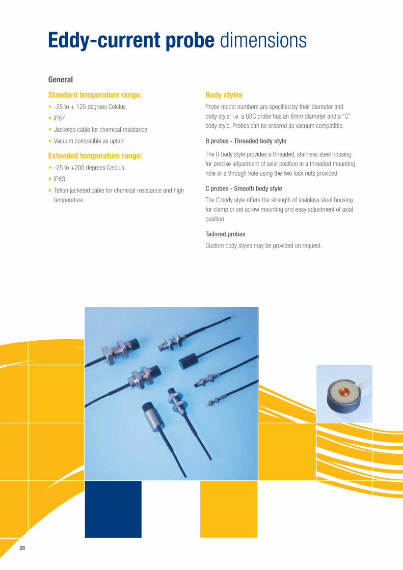
Eddy-current probe dimensions
Standard temperature range:• -25 to + 125 degrees Celcius
• IP67
•Jacketed cable for chemical resistance
•Vacuum compatible as option
Extended temperature range:• -25 to +200 degrees Celcius
• IP63
•Teflon jacketed cable for chemical resistance and high temperature
General
Body stylesProbe model numbers are specified by their diameter and body style: i.e. a U8C probe has an 8mm diameter and a “C” body style. Probes can be ordered as vacuum compatible.
B probes - Threaded body style
The B body style provides a threaded, stainless steel housing for precise adjustment of axial position in a threaded mounting hole or a through hole using the two lock nuts provided.
C probes - Smooth body style
The C body style offers the strength of stainless steel housing for clamp or set screw mounting and easy adjustment of axial position.
Tailored probes
Custom body styles may be provided on request.
29
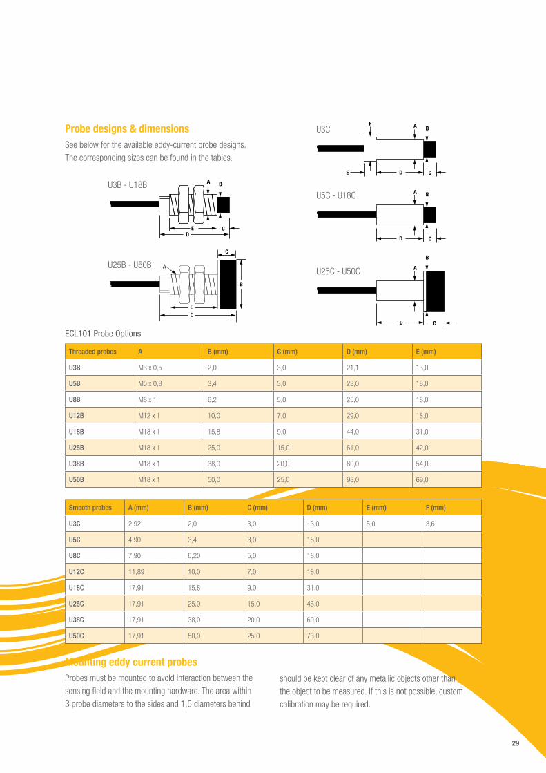
Probe designs & dimensionsSee below for the available eddy-current probe designs. The corresponding sizes can be found in the tables.
Mounting eddy current probesProbes must be mounted to avoid interaction between the sensing field and the mounting hardware. The area within 3 probe diameters to the sides and 1,5 diameters behind
should be kept clear of any metallic objects other than the object to be measured. If this is not possible, custom calibration may be required.
ECL101 Probe Options
Threaded probes A B (mm) C (mm) D (mm) E (mm)
U3B M3 x 0,5 2,0 3,0 21,1 13,0
U5B M5 x 0,8 3,4 3,0 23,0 18,0
U8B M8 x 1 6,2 5,0 25,0 18,0
U12B M12 x 1 10,0 7,0 29,0 18,0
U18B M18 x 1 15,8 9,0 44,0 31,0
U25B M18 x 1 25,0 15,0 61,0 42,0
U38B M18 x 1 38,0 20,0 80,0 54,0
U50B M18 x 1 50,0 25,0 98,0 69,0
Smooth probes A (mm) B (mm) C (mm) D (mm) E (mm) F (mm)
U3C 2,92 2,0 3,0 13,0 5,0 3,6
U5C 4,90 3,4 3,0 18,0
U8C 7,90 6,20 5,0 18,0
U12C 11,89 10,0 7,0 18,0
U18C 17,91 15,8 9,0 31,0
U25C 17,91 25,0 15,0 46,0
U38C 17,91 38,0 20,0 60,0
U50C 17,91 50,0 25,0 73,0
C E D
B A U3B - U18B
CDE
BAFU3C
CD
BAU5C - U18C
CD
B
AU25C - U50C
C
A
ED
B
U25B - U50B
30
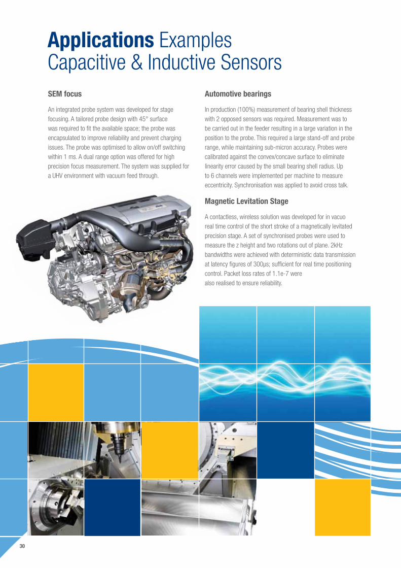
Applications Examples Capacitive & Inductive SensorsSEM focus
An integrated probe system was developed for stage focusing. A tailored probe design with 45° surface was required to fit the available space; the probe was encapsulated to improve reliability and prevent charging issues. The probe was optimised to allow on/off switching within 1 ms. A dual range option was offered for high precision focus measurement. The system was supplied for a UHV environment with vacuum feed through.
Automotive bearings
In production (100%) measurement of bearing shell thickness with 2 opposed sensors was required. Measurement was to be carried out in the feeder resulting in a large variation in the position to the probe. This required a large stand-off and probe range, while maintaining sub-micron accuracy. Probes were calibrated against the convex/concave surface to eliminate linearity error caused by the small bearing shell radius. Up to 6 channels were implemented per machine to measure eccentricity. Synchronisation was applied to avoid cross talk.
Magnetic Levitation Stage
A contactless, wireless solution was developed for in vacuo real time control of the short stroke of a magnetically levitated precision stage. A set of synchronised probes were used to measure the z height and two rotations out of plane. 2kHz bandwidths were achieved with deterministic data transmission at latency figures of 300µs; sufficient for real time positioning control. Packet loss rates of 1.1e-7 were also realised to ensure reliability.
31
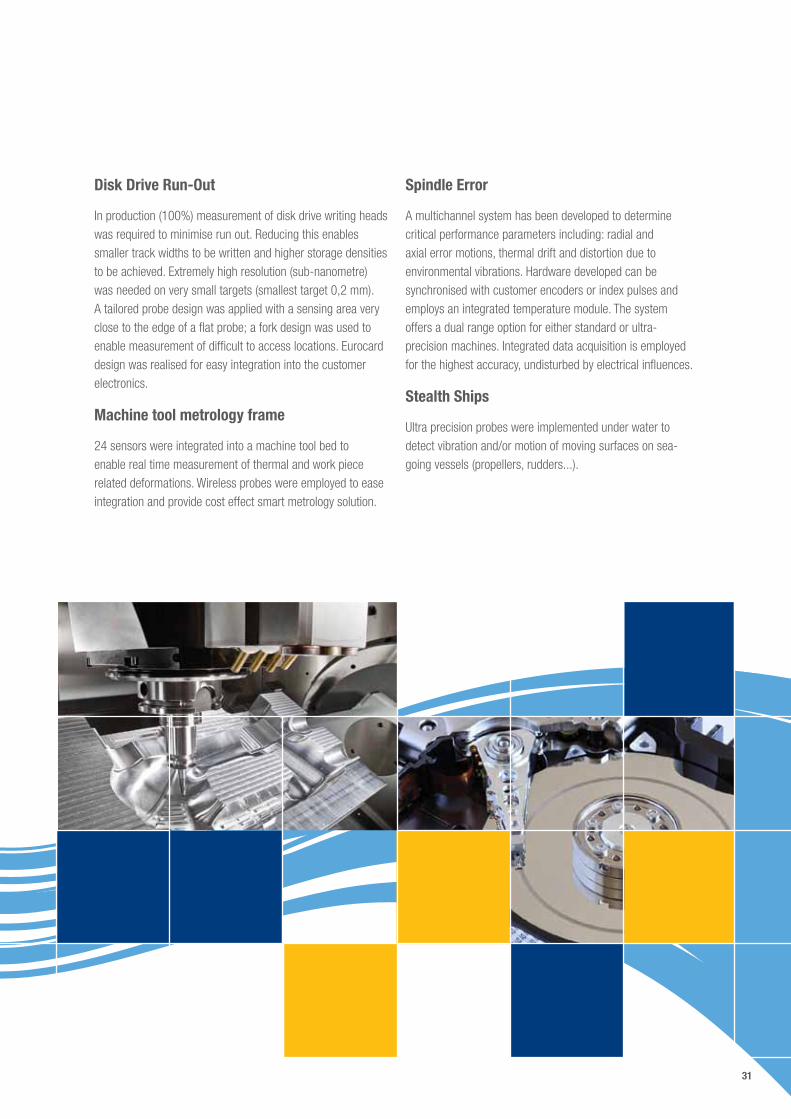
Disk Drive Run-Out
In production (100%) measurement of disk drive writing heads was required to minimise run out. Reducing this enables smaller track widths to be written and higher storage densities to be achieved. Extremely high resolution (sub-nanometre) was needed on very small targets (smallest target 0,2 mm). A tailored probe design was applied with a sensing area very close to the edge of a flat probe; a fork design was used to enable measurement of difficult to access locations. Eurocard design was realised for easy integration into the customer electronics.
Machine tool metrology frame
24 sensors were integrated into a machine tool bed to enable real time measurement of thermal and work piece related deformations. Wireless probes were employed to ease integration and provide cost effect smart metrology solution.
Spindle Error
A multichannel system has been developed to determine critical performance parameters including: radial and axial error motions, thermal drift and distortion due to environmental vibrations. Hardware developed can be synchronised with customer encoders or index pulses and employs an integrated temperature module. The system offers a dual range option for either standard or ultra-precision machines. Integrated data acquisition is employed for the highest accuracy, undisturbed by electrical influences.
Stealth Ships
Ultra precision probes were implemented under water to detect vibration and/or motion of moving surfaces on sea-going vessels (propellers, rudders...).

V.001.11.15
ww
w.gi
nger
-cre
ative
.com
IBS Precision Engineering BV (Head Office)
Esp 2015633 AD Eindhoven, The Netherlands
Telephone: +31 40 290 1270Fax: +31 40 290 1279E-mail: [email protected]
www.ibspe.com
IBS Precision Engineering Deutschland GmbH
Leitzstraße 4570469 Stuttgart, Germany
Telephone: +49 711 490 66 230Fax: +49 711 490 66 232
E-mail: [email protected] www.ibspe.de
IBS Precision Engineering sarl
Le Megellan, 7 rue Montespan91024 Evry Cedex, France
Telephone: +33 1 69 47 60 53Fax: +33 1 69 47 60 70
E-mail: [email protected] www.ibspe.fr