ultrasound controller model d72 - aq...
TRANSCRIPT
Ultrasound Controller
Manual
AQ M-Tech AB

2 Ultrasound Controller Manual
AQ M-Tech AB Ultrasound Controller Manual 3
Ultrasound Controller
D72, DP72, D128, G72, GP72, G128
AQ M-Tech AB
Manual version 5.20
Software version 5.2x
D72 hardware version RevE
DP72 hardware version RevE
D128 hardware version RevA
G72 hardware version RevA
GP72 hardware version RevA
GSD file version 5.0
The manual version should conform to the software and hardware version of the Ultrasound Controller.
The version of the Ultrasound Controller is shown briefly on the display when power is switched on. This manual is available at www.aqmtech.com
May 2017
4 Ultrasound Controller Manual
Table of contents
1. Manufacturer information ................................................................................................................. 6
Manufacturer Declaration of Conformity ......................................................................................... 6
Limited Warranty ............................................................................................................................ 6
Warning .......................................................................................................................................... 6
Certificate of Quality and Function ................................................................................................. 6
Manufacturer: ................................................................................................................................. 6
2. Introduction ....................................................................................................................................... 7
Ultrasound Controller ...................................................................................................................... 7
Installing Ultrasound Controller D72, G72 ...................................................................................... 7
Installing Ultrasound Controller DP72, GP72 ................................................................................. 8
Installing Ultrasound Controller D128, G128 .................................................................................. 8
3. Navigating the menu system ........................................................................................................... 9
Sensor MODE and the start-screen ............................................................................................... 9
4. Electric Noise................................................................................................................................... 10
Ground Connection and Sensor Cable ........................................................................................ 10
Noise from Variable Frequency Drives ......................................................................................... 10
5. Ex-installation with ex-barriers ...................................................................................................... 10
6. Air Sensor Mode .............................................................................................................................. 11
Quick start guide ........................................................................................................................... 11
Functional Description .................................................................................................................. 11
Orientation of the Air Sensor ........................................................................................................ 11
Connecting the Air Sensor............................................................................................................ 12
Connecting the Air Sensor Ex via zener-barrier ........................................................................... 13
Setting lowest possible sensitivity for bubbles ............................................................................. 13
SETTINGS .................................................................................................................................... 14
Air Sensor start-screen ................................................................................................................. 15
ADVANCED SETTINGS ............................................................................................................... 15
CALIBRATION .............................................................................................................................. 15
SHOW DATA ................................................................................................................................ 16
Calibration Data ............................................................................................................................ 16
Normal Measurement Data .......................................................................................................... 16
Very Low Sensitivity Data ............................................................................................................. 16
AUXILIARY DATA ........................................................................................................................ 17
HELP ............................................................................................................................................ 17
Sound velocity in the Air Sensor .................................................................................................. 17
Air Sensor TROUBLESHOOTING ............................................................................................... 17
7. Level Switch Mode .......................................................................................................................... 18
Quick start guide ........................................................................................................................... 18
Connecting the Level Switch ........................................................................................................ 18
Level Switch Type and Technique ............................................................................................... 18
Echo Technique ............................................................................................................................ 19
WR Technique .............................................................................................................................. 19
Mounting the Level Switch............................................................................................................ 19
Stainless Steel and Glass Containers .......................................................................................... 20
Level Switch start-screen ............................................................................................................. 20
SETTINGS .................................................................................................................................... 20
Container with jacket .................................................................................................................... 21
CALIBRATION .............................................................................................................................. 21
SHOW DATA ................................................................................................................................ 21
ADVANCED SETTINGS ............................................................................................................... 22
HELP ............................................................................................................................................ 22
Sound velocity and the Level Switch ............................................................................................ 22
Measurement Reliability ............................................................................................................... 22
Level Switch TROUBLESHOOTING ............................................................................................ 22
8. Level Sensor Mode ......................................................................................................................... 24
Quick start guide ........................................................................................................................... 24
Functional Description .................................................................................................................. 24
Connecting the level sensor ......................................................................................................... 25
Mounting the Sensor for level and velocity ................................................................................... 25
AQ M-Tech AB Ultrasound Controller Manual 5
Mounting the sensor for velocity ................................................................................................... 25
Installing the sensor on a non-horizontal bottom ......................................................................... 26
Container top ................................................................................................................................ 26
Level Sensor start-screen............................................................................................................. 26
SETTINGS .................................................................................................................................... 26
CALIBRATION .............................................................................................................................. 27
SHOW DATA ................................................................................................................................ 27
ADVANCED SETTINGS ............................................................................................................... 28
HELP ............................................................................................................................................ 28
Level Sensor TROUBLESHOOTING ........................................................................................... 28
9. Gel Distance Mode .......................................................................................................................... 30
Quick start guide ........................................................................................................................... 30
Functional Description .................................................................................................................. 30
Connecting the gel distance sensor ............................................................................................. 31
Gel Distance start-screen ............................................................................................................. 31
SETTINGS .................................................................................................................................... 31
CALIBRATION .............................................................................................................................. 32
SHOW DATA ................................................................................................................................ 32
ADVANCED SETTINGS ............................................................................................................... 32
HELP ............................................................................................................................................ 32
Gel Distance TROUBLESHOOTING ............................................................................................ 32
10. Gel Sensor Mode ............................................................................................................................. 33
Quick start guide ........................................................................................................................... 33
Connecting the Gel Sensor .......................................................................................................... 33
Measuring Gel .............................................................................................................................. 34
Measurement technique ............................................................................................................... 34
Mounting the Level Switch............................................................................................................ 35
Gel Sensor start-screen ................................................................................................................ 35
SETTINGS .................................................................................................................................... 36
CALIBRATION .............................................................................................................................. 36
SHOW DATA ................................................................................................................................ 37
ADVANCED SETTINGS ............................................................................................................... 37
HELP ............................................................................................................................................ 37
Measurement Reliability ............................................................................................................... 37
Gel Sensor TROUBLESHOOTING .............................................................................................. 38
11. Profibus DP ...................................................................................................................................... 39
Connecting Profibus ..................................................................................................................... 39
PROFIBUS Parameters ................................................................................................................ 39
Profibus Status-symbol ................................................................................................................. 39
Request Data ................................................................................................................................ 39
Response Data ............................................................................................................................. 40
Request Data table ....................................................................................................................... 40
TROUBLESHOOTING ................................................................................................................. 40
12. Technical specifications Ultrasound Controller .......................................................................... 42
13. Parameter settings .......................................................................................................................... 43
Air Sensor mode ........................................................................................................................... 43
Level Switch mode ....................................................................................................................... 43
Level Sensor mode ....................................................................................................................... 44
Gel Distance Sensor mode........................................................................................................... 44
Gel Sensor mode .......................................................................................................................... 45
PROFIBUS ................................................................................................................................... 45
14. Hardware and Software Version History ...................................................................................... 46
D72RevE and DP72RevE and D128RevA and G72RevA ........................................................... 46
D72RevD and DP72RevD ............................................................................................................ 47
6 Ultrasound Controller Manual
1. Manufacturer information
AQ M-Tech AB, (previously AQ Elteknik AB) operates a policy of on-going development and reserves the right to make changes and improvements to any of the products described in this manual without prior notice. Under no circumstances shall AQ M-Tech be held responsible for any loss or indirect damage howsoever caused. The content of this document is provided as it is. AQ M-Tech AB reserves the right to revise this document or withdraw it at any time without prior notice.
Manufacturer Declaration of Conformity
Manufacturer AQ M-Tech AB, Sweden declares, that the product: Ultrasound Controller marked with CE-label conforms with the following standards: EN 61000-6-2, EN 61000-6-4, EN55011 (Group 1, Class B).
Ultrasound Controller marked with conforms to WEEE directive 2012/19/EU. The Ultrasound Controller also conforms to RoHS directive 2011/65/EU. When the Ultrasound Controller is to be discarded, send it back to AQ M-Tech AB for safe disposal.
Limited Warranty
AQ M-Tech AB warrants to the original end user that the Ultrasound Controller is free from any defects in materials or workmanship for a period of one year from the date of purchase. During the warranty period, should the Ultrasound Controller have indications of failure due to faulty workmanship or materials, AQ M-Tech AB will replace it with no charge. This warranty shall not apply if the Ultrasound Controller is modified, misused or subjected to abnormal working conditions. Replacement as provided under this warranty is the only remedy of the purchaser. The purchaser pays freight to AQ M-Tech AB. AQ M-Tech AB shall in no event be held liable for indirect or consequential damages of any kind or character to the purchaser.
Warning
The Ultrasound Controller is intended to be used with the Air Sensor or the Level Switch, all of them manufactured by AQ M-Tech AB. AQ M-Tech AB takes no responsibility for any possible damage that could happen if any other sensor not manufactured by AQ M-Tech AB is connected to the Ultrasound Controller.
It is not allowed to repair or modify sensors or Ultrasound Controller.
Certificate of Quality and Function
AQ M-Tech AB guaranties that the Ultrasound Controller has passed function and quality tests.
Manufacturer:
AQ M-Tech AB Bolandsgatan 10 Phone: +46 184702900 SE-753 23 Uppsala Sweden www.aqmtech.se [email protected]
AQ M-Tech AB Ultrasound Controller Manual 7
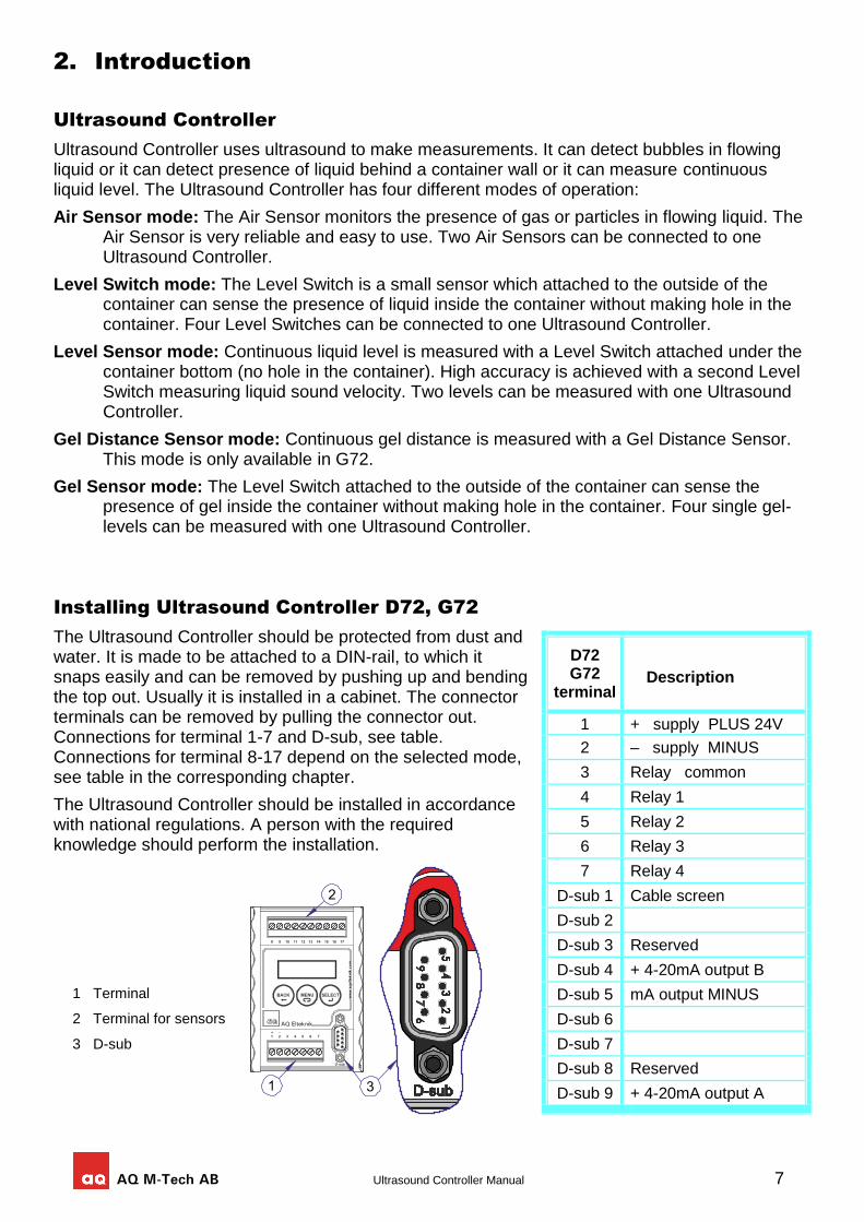
1 Terminal
2 Terminal for sensors
3 D-sub
2. Introduction
Ultrasound Controller
Ultrasound Controller uses ultrasound to make measurements. It can detect bubbles in flowing liquid or it can detect presence of liquid behind a container wall or it can measure continuous liquid level. The Ultrasound Controller has four different modes of operation:
Air Sensor mode: The Air Sensor monitors the presence of gas or particles in flowing liquid. The Air Sensor is very reliable and easy to use. Two Air Sensors can be connected to one Ultrasound Controller.
Level Switch mode: The Level Switch is a small sensor which attached to the outside of the container can sense the presence of liquid inside the container without making hole in the container. Four Level Switches can be connected to one Ultrasound Controller.
Level Sensor mode: Continuous liquid level is measured with a Level Switch attached under the container bottom (no hole in the container). High accuracy is achieved with a second Level Switch measuring liquid sound velocity. Two levels can be measured with one Ultrasound Controller.
Gel Distance Sensor mode: Continuous gel distance is measured with a Gel Distance Sensor. This mode is only available in G72.
Gel Sensor mode: The Level Switch attached to the outside of the container can sense the presence of gel inside the container without making hole in the container. Four single gel-levels can be measured with one Ultrasound Controller.
Installing Ultrasound Controller D72, G72
The Ultrasound Controller should be protected from dust and water. It is made to be attached to a DIN-rail, to which it snaps easily and can be removed by pushing up and bending the top out. Usually it is installed in a cabinet. The connector terminals can be removed by pulling the connector out. Connections for terminal 1-7 and D-sub, see table. Connections for terminal 8-17 depend on the selected mode, see table in the corresponding chapter.
The Ultrasound Controller should be installed in accordance with national regulations. A person with the required knowledge should perform the installation.
D72 G72
terminal Description
1 + supply PLUS 24V
2 – supply MINUS
3 Relay common
4 Relay 1
5 Relay 2
6 Relay 3
7 Relay 4
D-sub 1 Cable screen
D-sub 2
D-sub 3 Reserved
D-sub 4 + 4-20mA output B
D-sub 5 mA output MINUS
D-sub 6
D-sub 7
D-sub 8 Reserved
D-sub 9 + 4-20mA output A
8 Ultrasound Controller Manual
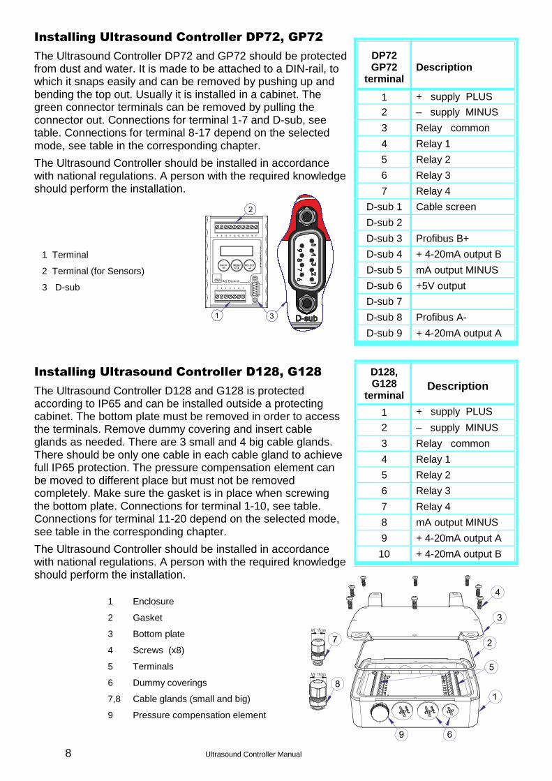
1 Terminal
2 Terminal (for Sensors)
3 D-sub
Installing Ultrasound Controller DP72, GP72
The Ultrasound Controller DP72 and GP72 should be protected from dust and water. It is made to be attached to a DIN-rail, to which it snaps easily and can be removed by pushing up and bending the top out. Usually it is installed in a cabinet. The green connector terminals can be removed by pulling the connector out. Connections for terminal 1-7 and D-sub, see table. Connections for terminal 8-17 depend on the selected mode, see table in the corresponding chapter.
The Ultrasound Controller should be installed in accordance with national regulations. A person with the required knowledge should perform the installation.
Installing Ultrasound Controller D128, G128
The Ultrasound Controller D128 and G128 is protected according to IP65 and can be installed outside a protecting cabinet. The bottom plate must be removed in order to access the terminals. Remove dummy covering and insert cable glands as needed. There are 3 small and 4 big cable glands. There should be only one cable in each cable gland to achieve full IP65 protection. The pressure compensation element can be moved to different place but must not be removed completely. Make sure the gasket is in place when screwing the bottom plate. Connections for terminal 1-10, see table. Connections for terminal 11-20 depend on the selected mode, see table in the corresponding chapter.
The Ultrasound Controller should be installed in accordance with national regulations. A person with the required knowledge should perform the installation.
DP72 GP72
terminal Description
1 + supply PLUS 24V 2 – supply MINUS
3 Relay common
4 Relay 1
5 Relay 2
6 Relay 3
7 Relay 4
D-sub 1 Cable screen
D-sub 2
D-sub 3 Profibus B+
D-sub 4 + 4-20mA output B
D-sub 5 mA output MINUS
D-sub 6 +5V output
D-sub 7
D-sub 8 Profibus A-
D-sub 9 + 4-20mA output A
D128, G128
terminal Description
1 + supply PLUS 24V 2 – supply MINUS
3 Relay common
4 Relay 1
5 Relay 2
6 Relay 3
7 Relay 4
8 mA output MINUS
9 + 4-20mA output A
10 + 4-20mA output B
1 Enclosure
2 Gasket
3 Bottom plate
4 Screws (x8)
5 Terminals
6 Dummy coverings
7,8 Cable glands (small and big)
9 Pressure compensation element
AQ M-Tech AB Ultrasound Controller Manual 9
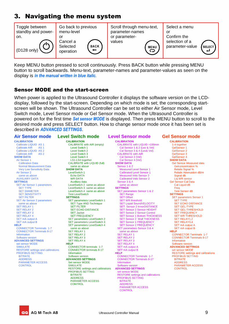
3. Navigating the menu system
Switches
Keep MENU button pressed to scroll continuously. Press BACK button while pressing MENU button to scroll backwards. Menu-text, parameter-names and parameter-values as seen on the display is in the manual written in blue italic.
Sensor MODE and the start-screen
When power is applied to the Ultrasound Controller it displays the software version on the LCD-display, followed by the start-screen. Depending on which mode is set; the corresponding start-screen will be shown. The Ultrasound Controller can be set to either Air Sensor mode, Level Switch mode, Level Sensor mode or Gel Sensor mode. When the Ultrasound Controller is powered on for the first time Set sensor MODE is displayed. Then press MENU button to scroll to the desired mode and press SELECT button. How to change sensor mode once it has been set is described in ADVANCED SETTINGS.
Air Sensor mode Level Switch mode Level Sensor mode Gel Sensor mode
CALIBRATION CALIBRATION CALIBRATION CALIBRATION Calibrate LIQUID AS 1 CALIBRATE with AIR (empty) CALIBRATE with LIQUID >100mm 1-4 together Calibrate AIR AS 1 Level Switch 1 Cal Sensor 1 & 2 (Lev & Vel) GelSensor 1 Calibrate LIQUID AS 2 Level Switch 2 Cal Sensor 3 & 4 (Lev& Vel) GelSensor 2 Calibrate AIR AS 2 Level Switch 3 CALIBRATE with AIR GelSensor 3 SHOW DATA Level Switch 4 Cal Sensor 2 (Vel) GelSensor 4 Air Sensor 1 LS1-LS4 together Cal Sensor 4 (Vel) SHOW DATA Calibration Data CALIBRATE with LIQUID (full) SHOW DATA Gel Sensor Measured data Normal Measurement Data same as above Sensor 1 & 2 Gelconcentration % Very Low Sensitivity Data SHOW DATA Measured Level Sensor 1 Relativ Signal %
Air Sensor 2 LevelSwitch 1 Calibrated Level Sensor 1 Relativ Attenuation dB/m same as above Echo DATA Measured Velo Sensor 2 Signal dB AUXILIARY DATA WR DATA Calibrated Velo Sensor 2 Liq WR sensor SETTINGS Auxiliary data Sensor 3 & 4 Gel Sensor Cal Data SET Air Sensor 1 parameters LevelSwitch 2 same as above same as above Cal Liquid dB SET TYPE LevelSwitch 3 same as above SETTINGS Freq
SET DIAMETER LevelSwitch 4 same as above SET parameters Sensor 1 & 2 Test Sensor dB SET SENSITIVITY Test LevelSwitch SET Range SETTINGS SET FILTER SETTINGS SET Offset SET parameters Sensor 1
SET Air Sensor 2 parameters SET parameters LevelSwitch 1 SET WR threshold SET TYPE same as above SET Type AND Technique SET Liquid SoundVELOCITY SET ECHO DISTANCE SET RELAY 1 SET FILTER SET Sensor 2 InnerDISTANCE SET GEL-TYPE SET RELAY 2 SET ECHO-DISTANCE SET Sensor 2 Sensor HEIGHT SET GEL-THRESHOLD SET RELAY 3 SET Jacket SET Sensor 2 Sensor Control SET FREQUENCY SET RELAY 4 SET FREQUENCY SET Sensor 1 Bottom THICKNESS SET WR THRESHOLD SET mA output A SET parameters LevelSwitch 2 SET Sensor 2 Wall THICKNESS SET RELAY1,2 SET mA output B SET parameters LevelSwitch 3 SET Sensor 1 FREQUENCY SET RELAY3,4 HELP SET parameters LevelSwitch 4 SET Sensor 2 FREQUENCY SET mA output A CONNECTOR Terminals 1-7 same as above SET parameters Sensor 3 & 4 SET mA output B CONNECTOR Terminals 8-17 SET RELAY 1 same as above HELP Information SET RELAY 2 SET RELAY 1 CONNECTOR Terminals 1-7 Software version SET RELAY 3 SET RELAY 2 CONNECTOR Terminals 8-17 ADVANCED SETTINGS SET RELAY 4 SET RELAY 3 Information set sensor MODE HELP SET RELAY 4 Software version SIMULATE CONNECTOR terminals 1-7 SET mA output A ADVANCED SETTINGS RESTORE settings and calibrations CONNECTOR terminals 8-17 SET mA output B set sensor MODE PROFIBUS SETTING Information HELP RESTORE settings and calibrations BITRATE Software version CONNECTOR Terminals 1-7 PROFIBUS SETTING ADDRESS ADVANCED SETTINGS CONNECTOR Terminals 8-17 BITRATE PARAMETER ACCESS Set sensor MODE Information ADDRESS CONTROL SIMULATE Software version PARAMETER ACCESS RESTORE settings and calibrations ADVANCED SETTINGS CONTROL
PROFIBUS SETTING set sensor MODE BITRATE RESTORE settings and calibrations ADDRESS PROFIBUS SETTING PARAMETER ACCESS BITRATE CONTROL ADDRESS PARAMETER ACCESS CONTROL
Toggle between standby and power-on.
(D128 only)
Go back to previous menu-level or Cancel a Selected operation
Scroll through menu-text, parameter-names or parameter- values
Select a menu or Confirm the selection of a parameter-value
10 Ultrasound Controller Manual
4. Electric Noise
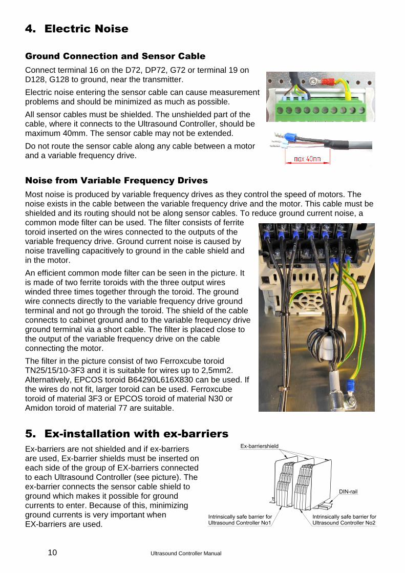
Ground Connection and Sensor Cable
Connect terminal 16 on the D72, DP72, G72 or terminal 19 on D128, G128 to ground, near the transmitter.
Electric noise entering the sensor cable can cause measurement problems and should be minimized as much as possible.
All sensor cables must be shielded. The unshielded part of the cable, where it connects to the Ultrasound Controller, should be maximum 40mm. The sensor cable may not be extended.
Do not route the sensor cable along any cable between a motor and a variable frequency drive.
Noise from Variable Frequency Drives
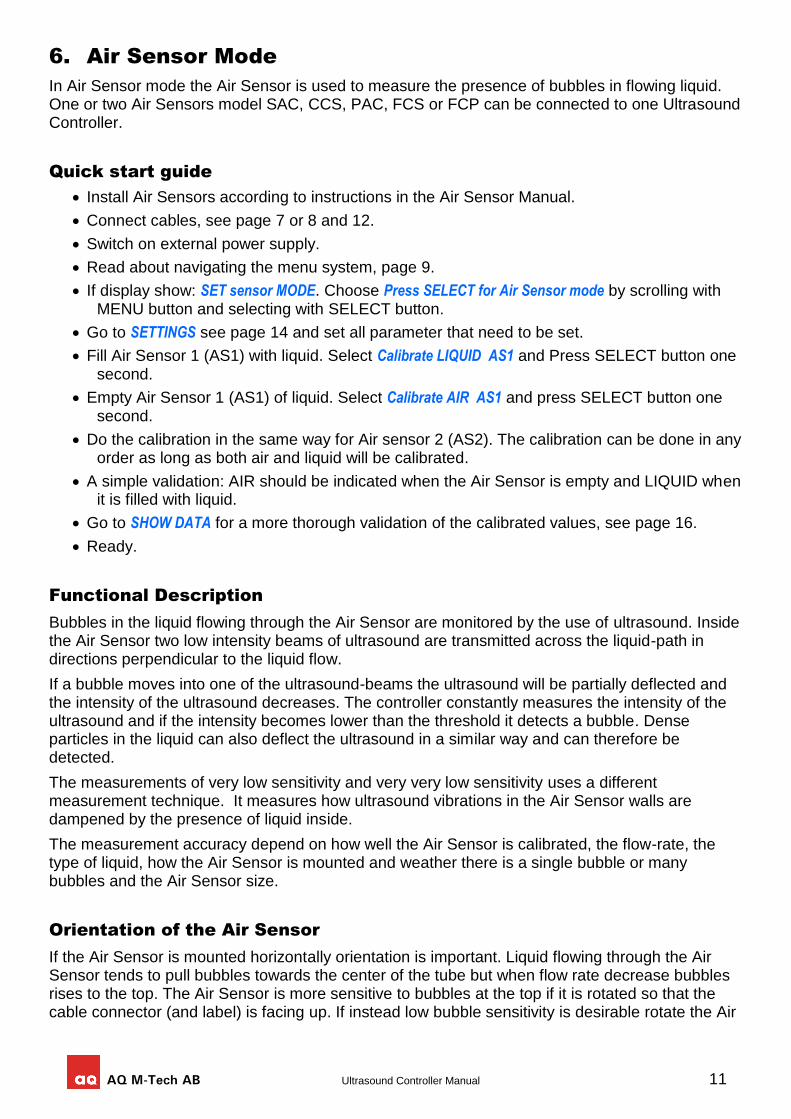
Most noise is produced by variable frequency drives as they control the speed of motors. The noise exists in the cable between the variable frequency drive and the motor. This cable must be shielded and its routing should not be along sensor cables. To reduce ground current noise, a common mode filter can be used. The filter consists of ferrite toroid inserted on the wires connected to the outputs of the variable frequency drive. Ground current noise is caused by noise travelling capacitively to ground in the cable shield and in the motor.
An efficient common mode filter can be seen in the picture. It is made of two ferrite toroids with the three output wires winded three times together through the toroid. The ground wire connects directly to the variable frequency drive ground terminal and not go through the toroid. The shield of the cable connects to cabinet ground and to the variable frequency drive ground terminal via a short cable. The filter is placed close to the output of the variable frequency drive on the cable connecting the motor.
The filter in the picture consist of two Ferroxcube toroid TN25/15/10-3F3 and it is suitable for wires up to 2,5mm2. Alternatively, EPCOS toroid B64290L616X830 can be used. If the wires do not fit, larger toroid can be used. Ferroxcube toroid of material 3F3 or EPCOS toroid of material N30 or Amidon toroid of material 77 are suitable.
5. Ex-installation with ex-barriers
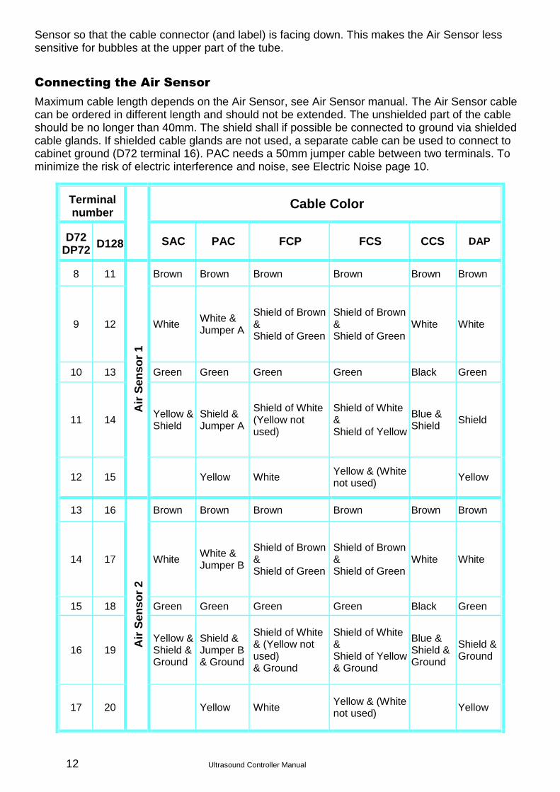
Ex-barriers are not shielded and if ex-barriers are used, Ex-barrier shields must be inserted on each side of the group of EX-barriers connected to each Ultrasound Controller (see picture). The ex-barrier connects the sensor cable shield to ground which makes it possible for ground currents to enter. Because of this, minimizing ground currents is very important when EX-barriers are used.
AQ M-Tech AB Ultrasound Controller Manual 11
6. Air Sensor Mode
In Air Sensor mode the Air Sensor is used to measure the presence of bubbles in flowing liquid. One or two Air Sensors model SAC, CCS, PAC, FCS or FCP can be connected to one Ultrasound Controller.
Quick start guide
Install Air Sensors according to instructions in the Air Sensor Manual.
Connect cables, see page 7 or 8 and 12.
Switch on external power supply.
Read about navigating the menu system, page 9.
If display show: SET sensor MODE. Choose Press SELECT for Air Sensor mode by scrolling with MENU button and selecting with SELECT button.
Go to SETTINGS see page 14 and set all parameter that need to be set.
Fill Air Sensor 1 (AS1) with liquid. Select Calibrate LIQUID AS1 and Press SELECT button one second.
Empty Air Sensor 1 (AS1) of liquid. Select Calibrate AIR AS1 and press SELECT button one second.
Do the calibration in the same way for Air sensor 2 (AS2). The calibration can be done in any order as long as both air and liquid will be calibrated.
A simple validation: AIR should be indicated when the Air Sensor is empty and LIQUID when it is filled with liquid.
Go to SHOW DATA for a more thorough validation of the calibrated values, see page 16.
Ready.
Functional Description
Bubbles in the liquid flowing through the Air Sensor are monitored by the use of ultrasound. Inside the Air Sensor two low intensity beams of ultrasound are transmitted across the liquid-path in directions perpendicular to the liquid flow.
If a bubble moves into one of the ultrasound-beams the ultrasound will be partially deflected and the intensity of the ultrasound decreases. The controller constantly measures the intensity of the ultrasound and if the intensity becomes lower than the threshold it detects a bubble. Dense particles in the liquid can also deflect the ultrasound in a similar way and can therefore be detected.
The measurements of very low sensitivity and very very low sensitivity uses a different measurement technique. It measures how ultrasound vibrations in the Air Sensor walls are dampened by the presence of liquid inside.
The measurement accuracy depend on how well the Air Sensor is calibrated, the flow-rate, the type of liquid, how the Air Sensor is mounted and weather there is a single bubble or many bubbles and the Air Sensor size.
Orientation of the Air Sensor
If the Air Sensor is mounted horizontally orientation is important. Liquid flowing through the Air Sensor tends to pull bubbles towards the center of the tube but when flow rate decrease bubbles rises to the top. The Air Sensor is more sensitive to bubbles at the top if it is rotated so that the cable connector (and label) is facing up. If instead low bubble sensitivity is desirable rotate the Air
12 Ultrasound Controller Manual
Sensor so that the cable connector (and label) is facing down. This makes the Air Sensor less sensitive for bubbles at the upper part of the tube.
Connecting the Air Sensor
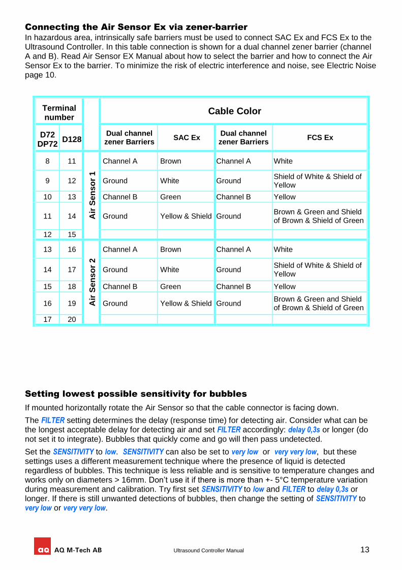
Maximum cable length depends on the Air Sensor, see Air Sensor manual. The Air Sensor cable can be ordered in different length and should not be extended. The unshielded part of the cable should be no longer than 40mm. The shield shall if possible be connected to ground via shielded cable glands. If shielded cable glands are not used, a separate cable can be used to connect to cabinet ground (D72 terminal 16). PAC needs a 50mm jumper cable between two terminals. To minimize the risk of electric interference and noise, see Electric Noise page 10.
Terminal number
Cable Color
D72 DP72
D128 SAC PAC FCP FCS CCS DAP
8 11
Air
Se
ns
or
1
Brown Brown Brown Brown Brown Brown
9 12 White White & Jumper A
Shield of Brown & Shield of Green
Shield of Brown & Shield of Green
White White
10 13 Green Green Green Green Black Green
11 14 Yellow & Shield
Shield & Jumper A
Shield of White (Yellow not used)
Shield of White & Shield of Yellow
Blue & Shield
Shield
12 15 Yellow White Yellow & (White not used)
Yellow
13 16
Air
Se
ns
or
2
Brown Brown Brown Brown Brown Brown
14 17 White White & Jumper B
Shield of Brown & Shield of Green
Shield of Brown & Shield of Green
White White
15 18 Green Green Green Green Black Green
16 19 Yellow & Shield & Ground
Shield & Jumper B & Ground
Shield of White & (Yellow not used) & Ground
Shield of White & Shield of Yellow & Ground
Blue & Shield & Ground
Shield & Ground
17 20 Yellow White Yellow & (White not used)
Yellow
AQ M-Tech AB Ultrasound Controller Manual 13
Connecting the Air Sensor Ex via zener-barrier
In hazardous area, intrinsically safe barriers must be used to connect SAC Ex and FCS Ex to the Ultrasound Controller. In this table connection is shown for a dual channel zener barrier (channel A and B). Read Air Sensor EX Manual about how to select the barrier and how to connect the Air Sensor Ex to the barrier. To minimize the risk of electric interference and noise, see Electric Noise page 10.
Setting lowest possible sensitivity for bubbles
If mounted horizontally rotate the Air Sensor so that the cable connector is facing down.
The FILTER setting determines the delay (response time) for detecting air. Consider what can be the longest acceptable delay for detecting air and set FILTER accordingly: delay 0,3s or longer (do not set it to integrate). Bubbles that quickly come and go will then pass undetected.
Set the SENSITIVITY to low. SENSITIVITY can also be set to very low or very very low, but these settings uses a different measurement technique where the presence of liquid is detected regardless of bubbles. This technique is less reliable and is sensitive to temperature changes and works only on diameters > 16mm. Don’t use it if there is more than +- 5°C temperature variation during measurement and calibration. Try first set SENSITIVITY to low and FILTER to delay 0,3s or longer. If there is still unwanted detections of bubbles, then change the setting of SENSITIVITY to very low or very very low.
Terminal number
Cable Color
D72 DP72
D128 Dual channel zener Barriers
SAC Ex Dual channel zener Barriers
FCS Ex
8 11
Air
Se
ns
or
1
Channel A Brown Channel A White
9 12 Ground White Ground Shield of White & Shield of Yellow
10 13 Channel B Green Channel B Yellow
11 14 Ground Yellow & Shield Ground Brown & Green and Shield of Brown & Shield of Green
12 15
13 16
Air
Se
ns
or
2
Channel A Brown Channel A White
14 17 Ground White Ground Shield of White & Shield of Yellow
15 18 Channel B Green Channel B Yellow
16 19 Ground Yellow & Shield Ground Brown & Green and Shield of Brown & Shield of Green
17 20
14 Ultrasound Controller Manual
SETTINGS
Through the SETTINGS-menu the parameters of the Air Sensor can be set.
Select SET TYPE to set the type of Air Sensor connected. This tells the Ultrasound Controller to make the correct adjustments for this Air Sensor type.
Select SET DIAMETER to set it to the diameter of the connected Air Sensor or as close as possible. This tells the Ultrasound Controller to make the correct adjustments for this Air Sensor diameter.
Select SET SENSITIVITY to set the sensitivity. This determines how sensitive the Air Sensor is for bubbles.
SENSITIVITY can be set to high, medium, low, very low and very very low. Detectable bubble size is somewhat dependent on Air Sensor inner diameter:
At high sensitivity, a single bubble of approximately 5μl can be detected (SAC10: 1μl, SAC22: 6μl, SAC35: 8μl)
At medium sensitivity, a single bubble of approximately 20μl can be detected (SAC10: 10μl, SAC22: 30μl, SAC35: 40μl)
At low sensitivity, a single bubble of approximately 700μl can be detected. (SAC10: 500μl, SAC22: 900μl, SAC35: 1000μl)
Low sensitivity is achieved by requiring both detectors inside the Air Sensor to detect bubbles at the same time. Many small bubbles together will be detected as if they were a single big bubble. Even tiny (microscopic almost invisible) bubbles will be detected if there are many of them.
High, medium and low sensitivity are the normal measurements.
At very low and very very low sensitivity a different measuring technique is used (WR-technique). This technique measures the presence of liquid or no liquid, making the Air Sensor very insensitive for bubbles. It can be used only for Air Sensors with diameter ≥ 22mm. It also have temperature dependence and should not be used if there are temperature variations of more than ±5ºC.
Select SET FILTER to set the filter-time. It determines how the measurement-data is filtered. FILTER can be set to either integrate 1ms - 3s or delay 300ms - 10s.
Integrate means integrating (adding) the duration of each bubble. When the sum becomes higher than the integrate time, air will be indicated. When liquid is next time indicated, the integration-process starts over.
Delay means that air will be indicated when air has been continuously detected for a time longer than the delay time.
Long FILTER delay and low SENSITIVITY is useful if some quantities of bubbles should be undetected.
Short FILTER integrate and high SENSITIVITY is useful when almost every bubble should be detected.
Select SET RELAY to set how the relays should act. There are four relays each with one normally open contact (at power off and when sensor is not connected the relay is open). Each relay can be set independently. Choose between Closed with air or closed with liquid and choose between Air Sensor 1 and Air Sensor 2. The duration of air being indicated is minimum 0,5 second even if the bubble is detected much shorter time (to make sure the indication of air is registered).
Select SET mA output to set the assignment of the mA-outputs. There are two outputs: A and B. They can be assigned to Air Sensor 1 or Air Sensor 2 and Normal Measurement Data or All Sensitivities
Normal Measurement Data Assigns a combination of the analog Ndata during the time liquid is indicated and 6mA when air is indicated: 8mA – 20mA = Ndata = 0% – 150% during the time Liquid is indicated
AQ M-Tech AB Ultrasound Controller Manual 15
6mA = when Air is indicated 4mA = error
All Sensitivities Assigns bubble sizes to mA. 16mA = Liquid (no bubble) 14mA = small bubble 12mA = medium bubble 10mA = big bubble 8mA = very big bubble 6mA = very very big bubble 4mA = error.
The bubble indication time is always minimum 0,5 second.
Air Sensor start-screen
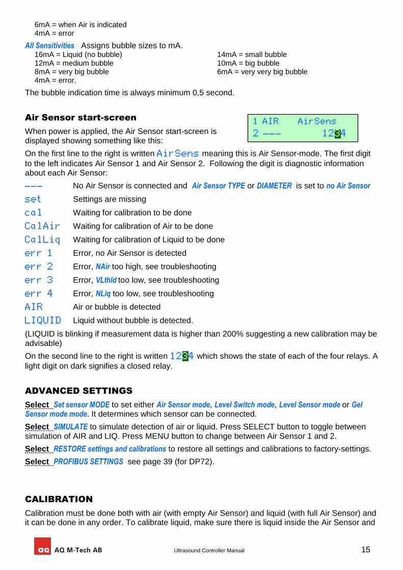
When power is applied, the Air Sensor start-screen is displayed showing something like this:
On the first line to the right is written AirSens meaning this is Air Sensor-mode. The first digit
to the left indicates Air Sensor 1 and Air Sensor 2. Following the digit is diagnostic information about each Air Sensor:
--- No Air Sensor is connected and Air Sensor TYPE or DIAMETER is set to no Air Sensor
set Settings are missing
cal Waiting for calibration to be done
CalAir Waiting for calibration of Air to be done
CalLiq Waiting for calibration of Liquid to be done
err 1 Error, no Air Sensor is detected
err 2 Error, NAir too high, see troubleshooting
err 3 Error, VLthld too low, see troubleshooting
err 4 Error, NLiq too low, see troubleshooting
AIR Air or bubble is detected
LIQUID Liquid without bubble is detected.
(LIQUID is blinking if measurement data is higher than 200% suggesting a new calibration may be advisable)
On the second line to the right is written 1234 which shows the state of each of the four relays. A
light digit on dark signifies a closed relay.
ADVANCED SETTINGS
Select Set sensor MODE to set either Air Sensor mode, Level Switch mode, Level Sensor mode or Gel Sensor mode mode. It determines which sensor can be connected.
Select SIMULATE to simulate detection of air or liquid. Press SELECT button to toggle between simulation of AIR and LIQ. Press MENU button to change between Air Sensor 1 and 2.
Select RESTORE settings and calibrations to restore all settings and calibrations to factory-settings.
Select PROFIBUS SETTINGS see page 39 (for DP72).
CALIBRATION
Calibration must be done both with air (with empty Air Sensor) and liquid (with full Air Sensor) and it can be done in any order. To calibrate liquid, make sure there is liquid inside the Air Sensor and
1 AIR AirSens
2 --- 1234
16 Ultrasound Controller Manual
select calibrate LIQUID (and press SELECT button one second). To calibrate air make sure the Air Sensor is empty and select calibrate AIR (and press SELECT button one second). During calibration of liquid, Ultrasound Controller adjusts the intensity of the ultrasound to become 100%. Each Air Sensor should be calibrated after installation. After the calibration it is advisable also to check the values in SHOW DATA (see below).
A new calibration of liquid may be required if the liquid properties has changed significantly since the last calibration. For the Air Sensor PAC or FCP a temperature change over 20ºC requires a new calibration of liquid.
SHOW DATA
There are two measurement techniques, normal measurement and very low sensitivity measurement. These are then doubled into two perpendicular measurements for increased reliability and sensitivity.
During normal measurement a beam of ultrasound is transmitted and the echo is amplified. A bubble scatters the sound causing reduced intensity. This is how a bubble is being detected.
During very low sensitivity measurements the Air Sensor transmits ultrasound and listens to how quickly vibrations inside the walls of the Air Sensor disappear into the liquid.
Calibration Data
The Calibration Data page shows calibration data from normal measurement. Calibration data is measured and stored during calibration. The two data on each line correspond to the two perpendicular measurements.
On the first line is NLiq which is the ultrasound strength measured in dB with liquid in the Air Sensor. NLiq is usually around 40dB, depending on type of Air Sensor. A high value means strong sound which is better than a low value. Check that NLiq is higher than 30dB for SAC and FCS, higher than 18dB for SAC Ex or FCS Ex, higher than 19dB for PAC and FCP.
On the second line is NAir which is the relative sound strength, relative to NLiq, with air in the Air Sensor. Ideally NAir should be 0% but as sound travels around the walls it will not be 0%. Check that NAir is less than 15%.
Normal Measurement Data
This page shows the current normal measurement data, Ndata (The two data correspond to the two perpendicular measurements). It is the relative ultrasound strength (relative to NLiq). With liquid in the Air Sensor, it should be near 100%, depending on the liquid. All liquids do not conduct sound equally well. If Ndata with liquid is > 130% or if it is < 80% it is advisable to calibrate the Air Sensor with liquid again.
With air in the Air Sensor, Ndata should be less than 15%. The threshold at which air bubble is detected depend on sensitivity setting and type and size of Air Sensor (approximately at high sensitivity threshold is 44% and at low sensitivity threshold is 27%).
Very Low Sensitivity Data
This page shows data from the very low sensitivity measurement. This measurement technique is different from the normal measurement technique and is used only for very low and very very low sensitivity settings. The two data on each line correspond to the two perpendicular measurements.
On the first line is VLdata showing the current measured ultrasound strength.
On the second line is VLthld showing the threshold. VLthld is measured and stored during calibration. Liquid is detected when VLdata is > VLthld. For reliable operation VLthld should be > 5.
AQ M-Tech AB Ultrasound Controller Manual 17
AUXILIARY DATA
This page shows unprocessed data from the Air Sensor. It can be used for troubleshooting when contacting AQ M-Tech AB.
HELP
Select HELP to show information about how to connect the Ultrasound Controller.
Sound velocity in the Air Sensor
With sensitivity set to low, medium or high and with two liquids having different sound velocities in the Air Sensor and with these liquids not well mixed, there can be false indication of air. The sound is refracted due to velocity change, as it travels from one liquid to another. Setting longer filter times and lower sensitivity can reduce such false indications of air.
Air Sensor TROUBLESHOOTING
Air or Liquid is indicated on the display but the relay does not change = RELAY setting is wrong.
Display shows: Cal Calibration should be done. CalAir Calibration Air should be done. CalLiq Calibration Liquid should be done. Set Settings of TYPE or DIAMETER is missing err 1 No Air Sensor is detected. The reason for this can be wrongly connected Air Sensor, or
faulty Air Sensor. err 2 The relative signal with Air is too strong (at low, medium or high sensitivity). err 2 is shown if
NAir is higher than 21-25%. The reason for high NAir can be: Calibration of AIR has been done with liquid in the Air Sensor. Or Wrong settings of Air
Sensor Type or Diameter. Or electric interference. Or a faulty Air Sensor. Or calibration of LIQUID has been done with liquid having lots of bubbles or particles attenuating the sound.
Electric interference will show itself as Ndata being unstable with Air in the Air Sensor. To minimize the risk of interference it is important that sources of interference like frequency inverters should use shielded cables between inverter and motor. Also any unshielded part of the cable between the Air Sensor and Ultrasound Controller should be short. If ex-barriers are used, Ex-barriershields must be used especially if there is more than one Ultrasound Controller.
err 3 There is not enough signal difference between air and liquid (at very low or very very low sensitivity). err 3 is shown if Very Low sensitivity threshold is not high enough for reliable measurement (VLthld<6). Air Sensor with diameter less than 22mm may have difficulty measuring at very low sensitivity. Change SENSITIVITY to low, medium or high instead.
err 4 The absolute signal with Liquid is too weak (at low, medium or high sensitivity). err 4 is shown if the calibrated data with Liquid, NLiq is lower than 31dB for SAC and FCS or 19dB for SAC Ex and FCS Ex or lower than 18dB for PAC or FCP.
The reason for this can be: Calibration of LIQUID has been done with air or liquid having lots of bubbles or particles attenuating the sound. Or wrong settings of Air Sensor Type or Diameter. Or Air Sensor is wrongly connected. Or Air Sensor is faulty
18 Ultrasound Controller Manual
7. Level Switch Mode
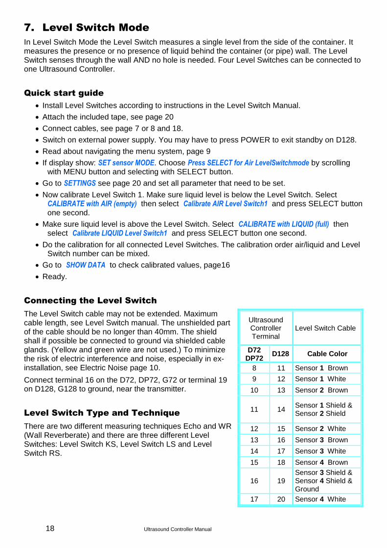
In Level Switch Mode the Level Switch measures a single level from the side of the container. It measures the presence or no presence of liquid behind the container (or pipe) wall. The Level Switch senses through the wall AND no hole is needed. Four Level Switches can be connected to one Ultrasound Controller.
Quick start guide
Install Level Switches according to instructions in the Level Switch Manual.
Attach the included tape, see page 20
Connect cables, see page 7 or 8 and 18.
Switch on external power supply. You may have to press POWER to exit standby on D128.
Read about navigating the menu system, page 9
If display show: SET sensor MODE. Choose Press SELECT for Air LevelSwitchmode by scrolling with MENU button and selecting with SELECT button.
Go to SETTINGS see page 20 and set all parameter that need to be set.
Now calibrate Level Switch 1. Make sure liquid level is below the Level Switch. Select CALIBRATE with AIR (empty) then select Calibrate AIR Level Switch1 and press SELECT button one second.
Make sure liquid level is above the Level Switch. Select CALIBRATE with LIQUID (full) then select Calibrate LIQUID Level Switch1 and press SELECT button one second.
Do the calibration for all connected Level Switches. The calibration order air/liquid and Level Switch number can be mixed.
Go to SHOW DATA to check calibrated values, page16
Ready.
Connecting the Level Switch
The Level Switch cable may not be extended. Maximum cable length, see Level Switch manual. The unshielded part of the cable should be no longer than 40mm. The shield shall if possible be connected to ground via shielded cable glands. (Yellow and green wire are not used.) To minimize the risk of electric interference and noise, especially in ex-installation, see Electric Noise page 10.
Connect terminal 16 on the D72, DP72, G72 or terminal 19 on D128, G128 to ground, near the transmitter.
Level Switch Type and Technique
There are two different measuring techniques Echo and WR (Wall Reverberate) and there are three different Level Switches: Level Switch KS, Level Switch LS and Level Switch RS.
Ultrasound Controller Terminal
Level Switch Cable
D72
DP72 D128 Cable Color
8 11 Sensor 1 Brown
9 12 Sensor 1 White
10 13 Sensor 2 Brown
11 14 Sensor 1 Shield & Sensor 2 Shield
12 15 Sensor 2 White
13 16 Sensor 3 Brown
14 17 Sensor 3 White
15 18 Sensor 4 Brown
16 19 Sensor 3 Shield & Sensor 4 Shield & Ground
17 20 Sensor 4 White
AQ M-Tech AB Ultrasound Controller Manual 19
Echo Technique
The echo-technique uses echo from a reflecting surface inside the container (usually the opposite container wall) to determine if there is liquid or not inside. Level Switch KS or Level Switch LS can be used but not Level Switch RS.
The echo-technique transmits short sounds and then measures the echo bouncing on the reflecting surface. When there is an echo, there is liquid inside and with no liquid there is no echo. The liquid must not attenuate the sound too much. Small bubbles and particles in the liquid can cause attenuation and unmixed liquids having different sound velocities can cause refraction of the sound and thereby wrong indication of low level. It is important that the sound-beam from the sensor is reflected back to the sensor and not diverted in the wrong direction.
It is desirable that the ultrasound passes as easy as possible through the container wall. How well it passes depend on the wall material and thickness. Steel or glass wall should be in the range 1,2mm - 15 mm and plastic wall <15mm (PP<10mm). Plastic with fiberglass can be troublesome. Testing on the actual container is recommended. Any welding or other unevenness in the wall should be avoided as it can refract (bend) the sound-beam in an unwanted direction.
The ultrasound beam behaves similar to a light-beam, the direction of the echo depend on from what angle it hits the reflecting surface. Obstructing object in the path between sensor and the reflecting surface should be avoided. The sound beam is approximately 1cm in diameter. A tube in the center of the container can give an echo but it is weak. In case there are obstructing objects inside the container, perhaps the Level Switch RS with the WR-technique is a better choice.
On small containers, disturbing background echoes becomes stronger in relation to the echo. Level Switch LS and KS should therefore not be used on containers smaller than 44mm diameter.
WR Technique
The WR technique measures vibrations in the container wall to determine if there is liquid or not behind the wall. Level Switch RS should be used (and on plastic walls Level Switch KS can also be used)
The WR-technique transmits sound and then measures how quickly vibrations in the container wall disappear. Vibrations in the wall disappear more quickly with liquid inside due to the dampening effect of the liquid. The WR-technique works with most liquids since the sound does not have to travel through the liquid. But the WR-technique is dependent on the material and thickness of the wall. Steel or glass wall 1,2mm - 15 mm or plastic wall < 15mm (PP<10mm) should be ok. Fiberglass-plastic could be troublesome and testing on the actual container is recommended. WR technique has quite high temperature dependence, depending on wall material, and should not be used if temperature differ more than 15ºC from temperature during calibration.
On plastic walls it is also possible to use Level Switch KS with the WR-technique. Level Switch KS can also be used with the WR-technique on a container with jacket to sense the presence of liquid in the inner container (if the gap between the jacket and the container is filled with liquid).
The WR-technique measures very small signal changes and is sensitive to small movements of the Level Switch. The Level Switch should therefore be glued with silicone. The WR-technique can also be sensitive to liquid drops remaining on the inside of the wall and sensitive to temperature changes. The advantage of the WR-technique is it is independent of liquid properties and there is no need for a reflecting surface.
Mounting the Level Switch
How to mount the Level Switch on the container is described in Level Switch manual.
20 Ultrasound Controller Manual
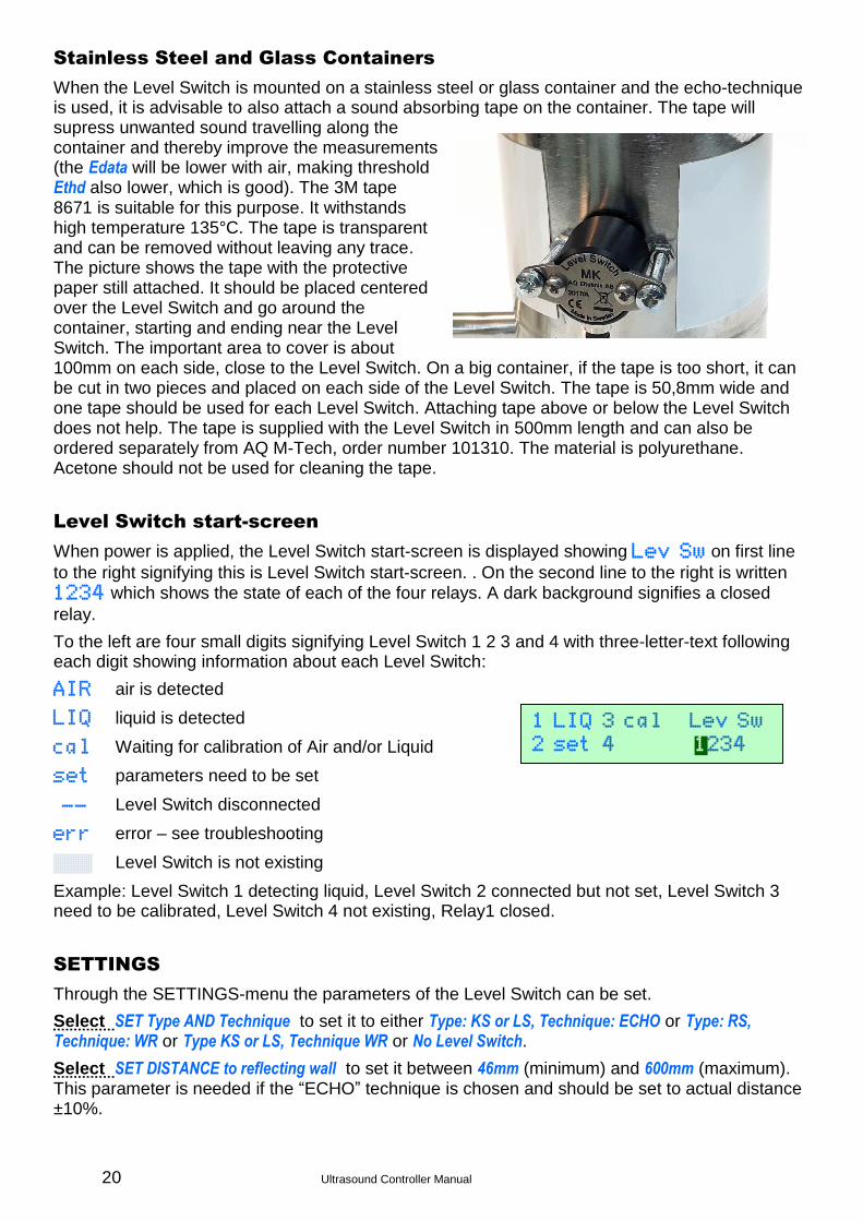
Stainless Steel and Glass Containers
When the Level Switch is mounted on a stainless steel or glass container and the echo-technique is used, it is advisable to also attach a sound absorbing tape on the container. The tape will supress unwanted sound travelling along the container and thereby improve the measurements (the Edata will be lower with air, making threshold Ethd also lower, which is good). The 3M tape 8671 is suitable for this purpose. It withstands high temperature 135°C. The tape is transparent and can be removed without leaving any trace. The picture shows the tape with the protective paper still attached. It should be placed centered over the Level Switch and go around the container, starting and ending near the Level Switch. The important area to cover is about 100mm on each side, close to the Level Switch. On a big container, if the tape is too short, it can be cut in two pieces and placed on each side of the Level Switch. The tape is 50,8mm wide and one tape should be used for each Level Switch. Attaching tape above or below the Level Switch does not help. The tape is supplied with the Level Switch in 500mm length and can also be ordered separately from AQ M-Tech, order number 101310. The material is polyurethane. Acetone should not be used for cleaning the tape.
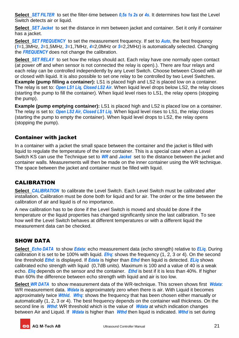
Level Switch start-screen
When power is applied, the Level Switch start-screen is displayed showing Lev Sw on first line
to the right signifying this is Level Switch start-screen. . On the second line to the right is written 1234 which shows the state of each of the four relays. A dark background signifies a closed
relay.
To the left are four small digits signifying Level Switch 1 2 3 and 4 with three-letter-text following each digit showing information about each Level Switch:
AIR air is detected
LIQ liquid is detected
cal Waiting for calibration of Air and/or Liquid
set parameters need to be set
-- Level Switch disconnected
err error – see troubleshooting
™™™ Level Switch is not existing
Example: Level Switch 1 detecting liquid, Level Switch 2 connected but not set, Level Switch 3 need to be calibrated, Level Switch 4 not existing, Relay1 closed.
SETTINGS
Through the SETTINGS-menu the parameters of the Level Switch can be set.
Select SET Type AND Technique to set it to either Type: KS or LS, Technique: ECHO or Type: RS, Technique: WR or Type KS or LS, Technique WR or No Level Switch.
Select SET DISTANCE to reflecting wall to set it between 46mm (minimum) and 600mm (maximum). This parameter is needed if the “ECHO” technique is chosen and should be set to actual distance ±10%.
1 LIQ 3 cal Lev Sw 2 set 4 1234
AQ M-Tech AB Ultrasound Controller Manual 21
Select SET FILTER to set the filter-time between 0,5s 1s 2s or 4s. It determines how fast the Level Switch detects air or liquid.
Select SET Jacket to set the distance in mm between jacket and container. Set it only if container has a jacket.
Select SET FREQUENCY to set the measurement frequency. If set to Auto, the best frequency (1=1,3MHz, 2=1,5MHz, 3=1,7MHz, 4=2,0MHz or 5=2,2MHz) is automatically selected. Changing the FREQUENCY does not change the calibration.
Select SET RELAY to set how the relays should act. Each relay have one normally open contact (at power off and when sensor is not connected the relay is open).). There are four relays and each relay can be controlled independently by any Level Switch. Choose between Closed with air or closed with liquid. It is also possible to set one relay to be controlled by two Level Switches. Example (pump filling a container): LS1 is placed high and LS2 is placed low on a container. The relay is set to: Open LS1 Liq, Closed LS2 Air. When liquid level drops below LS2, the relay closes (starting the pump to fill the container). When liquid level rises to LS1, the relay opens (stopping the pump).
Example (pump emptying container): LS1 is placed high and LS2 is placed low on a container. The relay is set to: Open LS2 Air, Closed LS1 Liq. When liquid level rises to LS1, the relay closes (starting the pump to empty the container). When liquid level drops to LS2, the relay opens (stopping the pump).
Container with jacket
In a container with a jacket the small space between the container and the jacket is filled with liquid to regulate the temperature of the inner container. This is a special case when a Level Switch KS can use the Technique set to WR and Jacket set to the distance between the jacket and container walls. Measurements will then be made on the inner container using the WR technique. The space between the jacket and container must be filled with liquid.
CALIBRATION
Select CALIBRATION to calibrate the Level Switch. Each Level Switch must be calibrated after installation. Calibration must be done both for liquid and for air. The order or the time between the calibration of air and liquid is of no importance.
A new calibration has to be done if the Level Switch is moved and should be done if the temperature or the liquid properties has changed significantly since the last calibration. To see how well the Level Switch behaves at different temperatures or with a different liquid the measurement data can be checked.
SHOW DATA
Select Echo DATA to show Edata: echo measurement data (echo strength) relative to ELiq. During calibration it is set to be 100% with liquid. Efrq: shows the frequency (1, 2, 3 or 4). On the second line threshold Ethd: is displayed. If Edata is higher than Ethd then liquid is detected. ELiq shows calibrated echo strength with liquid (0,7dB units). Maximum is 100 and a value of 40 is a weak echo. Eliq depends on the sensor and the container. Ethd is best if it is less than 40%. If higher than 60% the difference between echo strength with liquid and air is too low.
Select WR DATA to show measurement data of the WR-technique. This screen shows first Wdata: WR measurement data. Wdata is approximately zero when there is air. With Liquid it becomes approximately twice Wthld. Wfrq: shows the frequency that has been chosen either manually or automatically (1, 2, 3 or 4). The best frequency depends on the container wall thickness. On the second line is Wthd: WR threshold which is the value of Wdata at which indication changes between Air and Liquid. If Wdata is higher than Wthd then liquid is indicated. Wthd is set during
22 Ultrasound Controller Manual
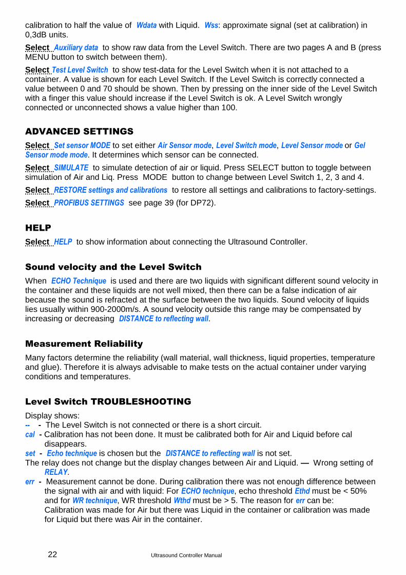
calibration to half the value of Wdata with Liquid. Wss: approximate signal (set at calibration) in 0,3dB units.
Select Auxiliary data to show raw data from the Level Switch. There are two pages A and B (press MENU button to switch between them).
Select Test Level Switch to show test-data for the Level Switch when it is not attached to a container. A value is shown for each Level Switch. If the Level Switch is correctly connected a value between 0 and 70 should be shown. Then by pressing on the inner side of the Level Switch with a finger this value should increase if the Level Switch is ok. A Level Switch wrongly connected or unconnected shows a value higher than 100.
ADVANCED SETTINGS
Select Set sensor MODE to set either Air Sensor mode, Level Switch mode, Level Sensor mode or Gel Sensor mode mode. It determines which sensor can be connected.
Select SIMULATE to simulate detection of air or liquid. Press SELECT button to toggle between simulation of Air and Liq. Press MODE button to change between Level Switch 1, 2, 3 and 4.
Select RESTORE settings and calibrations to restore all settings and calibrations to factory-settings.
Select PROFIBUS SETTINGS see page 39 (for DP72).
HELP
Select HELP to show information about connecting the Ultrasound Controller.
Sound velocity and the Level Switch
When ECHO Technique is used and there are two liquids with significant different sound velocity in the container and these liquids are not well mixed, then there can be a false indication of air because the sound is refracted at the surface between the two liquids. Sound velocity of liquids lies usually within 900-2000m/s. A sound velocity outside this range may be compensated by increasing or decreasing DISTANCE to reflecting wall.
Measurement Reliability
Many factors determine the reliability (wall material, wall thickness, liquid properties, temperature and glue). Therefore it is always advisable to make tests on the actual container under varying conditions and temperatures.
Level Switch TROUBLESHOOTING
Display shows: -- - The Level Switch is not connected or there is a short circuit. cal - Calibration has not been done. It must be calibrated both for Air and Liquid before cal
disappears. set - Echo technique is chosen but the DISTANCE to reflecting wall is not set. The relay does not change but the display changes between Air and Liquid. — Wrong setting of
RELAY. err - Measurement cannot be done. During calibration there was not enough difference between
the signal with air and with liquid: For ECHO technique, echo threshold Ethd must be < 50% and for WR technique, WR threshold Wthd must be > 5. The reason for err can be: Calibration was made for Air but there was Liquid in the container or calibration was made for Liquid but there was Air in the container.
AQ M-Tech AB Ultrasound Controller Manual 23
The Level Switch is not attached correctly to the container. There is a tiny air-gap between the Level Switch and the container. If ECHO technique is chosen and the DISTANCE to reflecting wall is wrong. If ECHO technique is chosen and the echo is reflected in a direction so it does not bounce back to the Level Switch. If ECHO technique is chosen and the something is obstruckting the sound beam. The liquid does not let through enough sound. Try using a Level Switch RS instead of a Level Switch LS. The container wall does not let through enough sound. Try a different FREQUENCY or set it to Auto. Wrong connection or faulty Level Switch. Select Test Level Switch: to test the level switch and its connection.
Electric interference can show itself as Edata being unstable with Air or Wdata being unstable with liquid. To minimize the risk of interference see Electric Noise page 10.
24 Ultrasound Controller Manual
8. Level Sensor Mode
In Level Sensor mode a sensor is attached at the bottom of the container and measures the continuous liquid level. The sensor is attached outside the container and senses through the bottom (no hole is needed). A second sensor measuring sound velocity can also be attached.
Four sensors can be attached to one Ultrasound Controller, measuring the level in two containers.
Quick start guide
Install sensors according to instructions on page 25 and instructions in Level Switch Manual.
Connect cables, see page 7 or 8 and 25
Switch on external power supply.
Read about navigating the menu system, page 9
If display show: SET sensor MODE. Choose Press SELECT for LevelSensormode by scrolling with MENU button and selecting with SELECT button.
Go to SETTINGS see page 26 and set all parameter that need to be set.
Calibrate with liquid sensor 1 & 2: Fill container to at least 100mm and above Sensor 2. Select Calibrate with LIQUID, Select Cal Sensor 1 & 2 (Lev & Vel) and Press SELECT button one second.
Empty container (level below Sensor 2). Select Calibrate with AIR, Select Cal Sensor 2 (Vel) and Press SELECT button one second.
If sensor 3 and 4 exist, do the calibration for them also in similar way.
Go to SHOW DATA to check calibrated values, page 27.
Ready.
Functional Description
A Level Switch-type of sensor is attached under the container bottom. It sends ultrasound through the bottom and through the liquid, and then receives the echo bouncing off the liquid surface. The Ultrasound Controller then calculates the liquid level.
This measurement technique is dependent on sound velocity which can vary with liquid and temperature. By using a second sensor attached on the vertical wall of the container the velocity can be measured and compensate for it. It measures the velocity by measuring the echo from the opposite container wall. In addition, it also makes level switch measurement telling if there is liquid or not behind the wall and this can be used for setting limits for the level measurement, improving reliability see SETTINGS.
It is important the echo is as strong as possible. Sound is attenuated by travelling through the bottom and through the liquid. Small bubbles and particles in the liquid also causes attenuation. The sensor need to be fairly horizontal (parallell to the liquid surface) in order for the echo to bounce back in the correct direction. If the liquid surface is disturbed by waves or vortex then the echo may only sometimes bounce back correctly. Unmixed liquids having different sound velocities can cause refraction of the sound so it bends and do not bounce back to the sensor. The strength of the echo can be checked in SHOW DATA.
When the container is empty it is difficult to measure the level as there is no echo. Also levels below 20mm are difficult to measure since the echo is close to echoes within the bottom. A special measurement technique (Wall-Reverberation measurement technique WR) is used for measuring empty container. It measures how much echoes bouncing within the bottom is dampened by the liquid.
Level Switch KSF should be used as sensor for level and Level Switch KS for velocity. Level Switch RS cannot be used and Level Switch LS is not recommended.
AQ M-Tech AB Ultrasound Controller Manual 25
Connecting the level sensor
The Level Sensor cable may not be extended. Maximum cable length, see Level Switch manual. The unshielded part of the cable should be no longer than 40mm. The shield shall if possible be connected to ground via shielded cable glands. To minimize the risk of electric interference and noise, especially in ex-installation, see Electric Noise page 10.
Connect terminal 16 on the D72, DP72, G72 or terminal 19 on D128, G128 to ground, near the transmitter.
Mounting the Sensor for level
and velocity
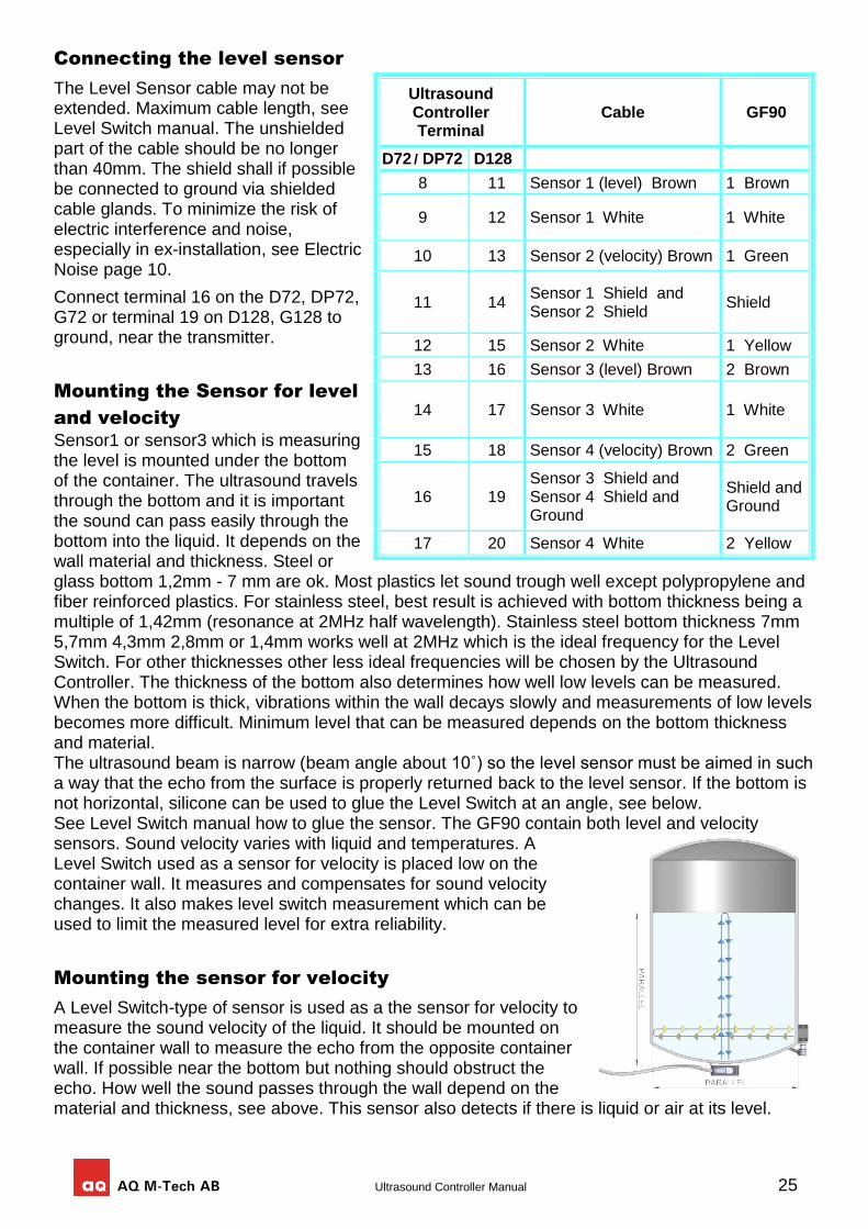
Sensor1 or sensor3 which is measuring the level is mounted under the bottom of the container. The ultrasound travels through the bottom and it is important the sound can pass easily through the bottom into the liquid. It depends on the wall material and thickness. Steel or glass bottom 1,2mm - 7 mm are ok. Most plastics let sound trough well except polypropylene and fiber reinforced plastics. For stainless steel, best result is achieved with bottom thickness being a multiple of 1,42mm (resonance at 2MHz half wavelength). Stainless steel bottom thickness 7mm 5,7mm 4,3mm 2,8mm or 1,4mm works well at 2MHz which is the ideal frequency for the Level Switch. For other thicknesses other less ideal frequencies will be chosen by the Ultrasound Controller. The thickness of the bottom also determines how well low levels can be measured. When the bottom is thick, vibrations within the wall decays slowly and measurements of low levels becomes more difficult. Minimum level that can be measured depends on the bottom thickness and material. The ultrasound beam is narrow (beam angle about 10˚) so the level sensor must be aimed in such a way that the echo from the surface is properly returned back to the level sensor. If the bottom is not horizontal, silicone can be used to glue the Level Switch at an angle, see below. See Level Switch manual how to glue the sensor. The GF90 contain both level and velocity sensors. Sound velocity varies with liquid and temperatures. A Level Switch used as a sensor for velocity is placed low on the container wall. It measures and compensates for sound velocity changes. It also makes level switch measurement which can be used to limit the measured level for extra reliability.
Mounting the sensor for velocity
A Level Switch-type of sensor is used as a the sensor for velocity to measure the sound velocity of the liquid. It should be mounted on the container wall to measure the echo from the opposite container wall. If possible near the bottom but nothing should obstruct the echo. How well the sound passes through the wall depend on the material and thickness, see above. This sensor also detects if there is liquid or air at its level.
Ultrasound Controller Terminal
Cable GF90
D72 / DP72 D128
8 11 Sensor 1 (level) Brown 1 Brown
9 12 Sensor 1 White 1 White
10 13 Sensor 2 (velocity) Brown 1 Green
11 14 Sensor 1 Shield and Sensor 2 Shield
Shield
12 15 Sensor 2 White 1 Yellow
13 16 Sensor 3 (level) Brown 2 Brown
14 17 Sensor 3 White 1 White
15 18 Sensor 4 (velocity) Brown 2 Green
16 19 Sensor 3 Shield and Sensor 4 Shield and Ground
Shield and Ground
17 20 Sensor 4 White 2 Yellow
26 Ultrasound Controller Manual
Installing the sensor on a non-horizontal bottom
If the bottom is not horizontal or has uneven thickness, a thick layer of silicone can be used to glue the sensor in a more horizontal position. In this case the sensor should be connected to Ultrasound Controller and be active measuring before it is being glued so that the position can be adjusted for the strongest echo. Fill the container half or more and attach the sensor with silicone between sensor and bottom. Calibrate with liquid and go to Measured Level Sensor. The echo strength is shown in dB. Small adjustments can be made of the angle of the sensor and the thickness of the silicone in order to achieve maximum echo strength. Find the best position and calibrate with liquid again and check position again for maximum echo strength. Then keep the level sensor fixed until the silicone cures.
Container top
When the container is full with liquid all the way up to the top the ultrasound will bounce off the top instead of off the liquid surface. Ideally the top should be parallell with the sensor and rather not conical. If it must be conical, a small angle is prefferred or a small non conical part of the radius above the sensor.
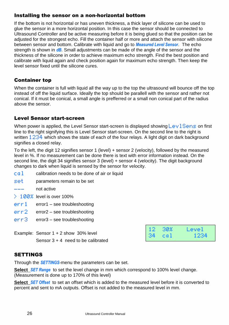
Level Sensor start-screen
When power is applied, the Level Sensor start-screen is displayed showing LevlSens on first
line to the right signifying this is Level Sensor start-screen. On the second line to the right is written 1234 which shows the state of each of the four relays. A light digit on dark background
signifies a closed relay.
To the left, the digit 12 signifies sensor 1 (level) + sensor 2 (velocity), followed by the measured level in %. If no measurement can be done there is text with error information instead. On the second line, the digit 34 signifies sensor 3 (level) + sensor 4 (velocity). The digit background changes to dark when liquid is sensed by the sensor for velocity.
cal calibration needs to be done of air or liquid
set parameters remain to be set
--- not active
> 100% level is over 100%
err1 error1 – see troubleshooting
err2 error2 – see troubleshooting
err3 error3 – see troubleshooting
Example: Sensor 1 + 2 show 30% level
Sensor 3 + 4 need to be calibrated
SETTINGS
Through the SETTINGS-menu the parameters can be set.
Select SET Range to set the level change in mm which correspond to 100% level change. (Measurement is done up to 170% of this level)
Select SET Offset to set an offset which is added to the measured level before it is converted to percent and sent to mA outputs. Offset is not added to the measured level in mm.
12 30% Level 34 cal 1234
AQ M-Tech AB Ultrasound Controller Manual 27
Select SET Sensor WR threshold to set the threshold (in dB) for very low level echo to be detected using WR-technique. Higher value makes it less sensitive. A smaller value makes it more sensitive but with higher risk of wrongly detecting low level when there is high level.
Select SET Liquid Sound Velocity This parameter is used if there is no sensor for velocity. It should be set to the correct velocity for the liquid.
Select SET Sensor InnerDISTANCE to set the inner diameter (in mm). If no sensor for velocity exist this parameter should be set to [not set].
Select SET Sensor HEIGHT to set the height (in mm) above the bottom where the sensor for velocity is attached. If this value is set, the level measurements of the velocity sensor can be used to set limits for the level measurement.
Select SET Sensor Control to set how the air/liquid measurements of the sensor for velocity is used. Set it to Level unaffected if it should not be used. Set it to Limit level if it should limit the level measurements. This can improve reliability.
Select SET Sensor Bottom-Thickness This is used to compensate for sound travelling time through the bottom of the container.
Select SET Sensor Wall-Thickness This is used to compensate for sound travelling time through the wall.
Select SET Sensor1/3 FREQUENCY This is the frequency used for the level sensor. Usually Auto is good choice or manually try different frequency depending on container bottom thickness.
Select SET Sensor2/4 FREQUENCY This is the frequency used for the velocity sensor. Usually Auto is good choice or manually try different frequency depending on container wall thickness.
Select SET RELAY to set how the relays should act. Each relay have one normally open contact (at power off the relay is open).
Fixed settings for GF90: Sensor WR threshold: disabled, InnerDISTANCE: 90mm, Sensor HEIGHT: not set, Sensor Control: level unaffected, Sensor Bottom-Thickness: GF90, Sensor Wall-Thickness: GF90, Sensor1/3 FREQUENCY: 2,0MHz, Sensor2/4 FREQUENCY: 2,2MHz
CALIBRATION
Select CALIBRATION to calibrate. Calibration must be done after installation. Calibration should be done for liquid with minimum 100mm liquid level and minimum above the sensor for velocity. Do not fill completely if the container top is conical and do not reflect the echo so well. During calibration Ultrasound Controller tries different frequencies and selects the one with the strongest echo. Calibration should also be done for Air if there is a sensor for velocity (then liquid level must be below the sensor for velocity). Air calibration is only necessary if a sensor for velocity is used. If possible calibrate with a similar type of liquid as what is going to be used later.
If there is a velocity sensor the calibration measures the sound velocity and this measurement will be used when the liquid level is below the velocity sensor.
It is important to check (in SHOW DATA) that the calibration value of the echo is higher than 20dB.
A new calibration must be done if a sensor is moved or removed.
It is recommended to perform a new calibration every year to compensate for possible slow changes.
SHOW DATA
Select Measured Level Sensor: to show measured level mm, echo strength dB, the amount of background noise dBnoise, dBWR which is the strength of very low level echo. Check that the value of echo strength dB is high and dB noise is low.
28 Ultrasound Controller Manual
Select Calibrated Level Sensor: to show calibrated echo strength dB and calibrated selected frequency MHz.
Select Measured velo Sensor to show echo strength % of calibrated strength with liquid and dB and used velocity m/s and weather there is AIR or LIQ behind sensor 2.
Select Calibrated Velo Sensor to show calibrated velocity m/s, calibrated echo strength dB, calibrated frequency MHz and calibrated threshold for detecting liquid %.
Select Low level WR-measurements to show data from low level measurements (for troubleshooting use only)
ADVANCED SETTINGS
Select Set sensor MODE to set either Air Sensor mode, Level Switch mode, Level Sensor mode or Gel Sensor mode mode. It determines which sensor can be connected.
Select RESTORE settings and calibrations to restore all settings and calibrations to factory-settings.
Select PROFIBUS SETTINGS see page 39 (for DP72).
HELP
Select HELP to show information about connecting the Ultrasound Controller.
Level Sensor TROUBLESHOOTING
Display shows: set Some setting is missing cal Calibration of air and/or liquid must to be done. >100% Measured level is >100%. Consider changing Range. err1 During calibration with liquid, the echo from the level sensor is missing or very weak. err2 During calibration, the difference in strength between echo with liquid and with air is too
small. err3 During calibration, the echo with liquid from the velocity sensor is too weak.
Container is full and the inside surface of the top of the container is shaped in such a way that echoes are reflected in wrong direction. – Make a small portion of the inside surface flat just above the level sensor.
Level sensor is aimed in wrong direction. – Aim the level sensor in the right direction.
The container is inclined and thereby the echo is bounced off in wrong direction. – Unincline the container or aim the level sensor to correct it.
The echo strength dB, dBnoise and dBWR should be checked. In order for Ultrasound Controller to measure the level it needs echoes from the surface. Due to various reasons however the echoes can become too weak to be detected. Echo strength dB indicates how strong the echo is and should be compared to dB noise which is the background noise. In an empty container there is no echo. If the echo strength dB is not higher than 10dB above dBnoise there can be difficulties measuring the level. Make sure the echo is reflected properly back to the level sensor and that the Level Switch is horizontal. The bottom thickness and material also influences the echo strength, see Mounting the Level Sensor. If bottom thickness is such that resonance is not at 2MHz the echo is weaker. Bubbles or particles scatter the echo.
dBWR shows the strength of low level echoes (0-20mm) using the WR-technique. Low level echoes dBWR are compared with the WR threshold and if dBWR is above this threshold and Velocity Sensor detects low level then the WR-technique measurement takes over and forces the level to be whatever it measures. If WR threshold is lower it becomes more sensitive but risk increases of
AQ M-Tech AB Ultrasound Controller Manual 29
wrong detection due to temperature changes. Empty container gives rather weak low level dBWR indication. In an empty container there is no echo from a surface and the WR-technique is then comparing the echoes within the bottom with calibrated echoes within the bottom as measured with liquid. With higher WR threshold the WR-technique becomes less sensitive and may miss detecting empty container. Set to disabled, WR-technique is disabled.
30 Ultrasound Controller Manual
9. Gel Distance Mode
In Gel Distance mode, a Gel Distance Sensor measures the distance to the gelbed.
Ultrasound Controller G72 must be used for this mode. One sensor can be attached.
Quick start guide
Connect the gel distance sensor cable to G72 terminal: Red to 8 white to 9 and shield to 11. Connect power supply to G72 terminal: Plus 24V to 1 and minus to 2.
Switch on external power supply.
Read about navigating the menu system, page 9
If display show: SET sensor MODE. Choose Press SELECT for GelDistance mode by scrolling with MENU button and selecting with SELECT button.
Go to SETTINGS see page 31 and set the parameter that need to be set.
Calibrate with liquid: Fill container and make sure the distance to the gelbed is > 40mm and there are no bubbles under the sensor. Select CALIBRATION with Liquid, and Press SELECT button one second.
Functional Description
A Gel Distance Sensor sends ultrasound through the liquid, which then bounces back at the gelbed surface. G72 measures the echo and calculates the distance. The distance and echo strength is shown on the display.
When gelbed is expanded the gelbed surface becomes diffuse and the measured distance will be approximate. Also, the echo becomes weaker. When echo is weaker than 15dB the measurement can be unreliable. Small bubbles and particles in the liquid also causes echoes. The sensor need to be fairly horizontal (parallel to the gelbed surface) in order for the echo to bounce back properly. Unmixed liquids having different sound velocities can cause refraction of the sound so it does not bounce back to the sensor.
Measuring short distance (<20mm) can be difficult due to remaining vibrations inside the sensor. The measurement technique is dependent on sound velocity which can vary with liquid and temperature.
The mA output can be set to output distance (0% Level = 4mA, 100% Level = 20mA) or Signal strength (0dB = 4mA, 85dB = 20mA). It is adviseable to check the signal strength also during testing.
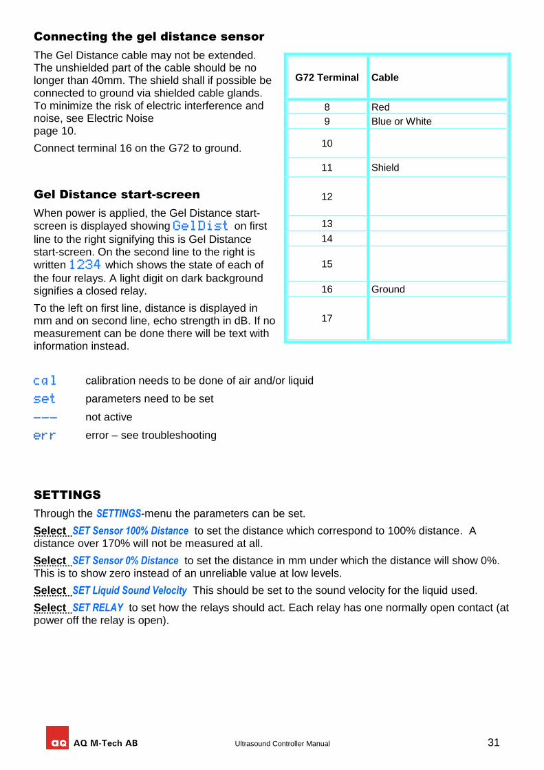
AQ M-Tech AB Ultrasound Controller Manual 31
Connecting the gel distance sensor
The Gel Distance cable may not be extended. The unshielded part of the cable should be no longer than 40mm. The shield shall if possible be connected to ground via shielded cable glands. To minimize the risk of electric interference and noise, see Electric Noise page 10.
Connect terminal 16 on the G72 to ground.
Gel Distance start-screen
When power is applied, the Gel Distance start-screen is displayed showing GelDist on first
line to the right signifying this is Gel Distance start-screen. On the second line to the right is
written 1234 which shows the state of each of
the four relays. A light digit on dark background signifies a closed relay.
To the left on first line, distance is displayed in mm and on second line, echo strength in dB. If no measurement can be done there will be text with information instead.
cal calibration needs to be done of air and/or liquid
set parameters need to be set
--- not active
err error – see troubleshooting
SETTINGS
Through the SETTINGS-menu the parameters can be set.
Select SET Sensor 100% Distance to set the distance which correspond to 100% distance. A distance over 170% will not be measured at all.
Select SET Sensor 0% Distance to set the distance in mm under which the distance will show 0%. This is to show zero instead of an unreliable value at low levels.
Select SET Liquid Sound Velocity This should be set to the sound velocity for the liquid used.
Select SET RELAY to set how the relays should act. Each relay has one normally open contact (at power off the relay is open).
G72 Terminal Cable
8 Red
9 Blue or White
10
11 Shield
12
13
14
15
16 Ground
17
32 Ultrasound Controller Manual
CALIBRATION
Select CALIBRATION to calibrate with liquid. Calibration must be done after installation. Fill container and make sure the distance to the gelbed is > 40mm and there are no bubbles under the sensor. Select CALIBRATION with Liquid, and Press SELECT button one second.
SHOW DATA
Select Measured Distance: to show measured distance mm, echo strength dB and noise strength dB noise. Check that the value of echo strength dB is high and dB noise is lower.
Select Calibrated Distance: to show calibrated echo strength dB and calibrated selected frequency MHz.
ADVANCED SETTINGS
Select Set sensor MODE to set either Air Sensor mode, Level Switch mode, Level Sensor mode, Gel Sensor mode mode, or Gel Distance mode. It determines which sensor can be connected.
Select RESTORE settings and calibrations to restore all settings and calibrations to factory-settings.
HELP
Select HELP to show information about connecting the Ultrasound Controller.
Gel Distance TROUBLESHOOTING
Display shows: set Setting is missing cal Calibration of liquid must to be done. err During calibration with liquid, the echo from the level sensor is missing or very weak.
For Ultrasound Controller to measure the level well it needs detectable echoes from the gel surface. Due to various reasons, the echoes can become too weak to be able to be detected. Echo strength dB shows how strong the echo is and and dB noise shows how strong the noise is. In air, there is no echo.
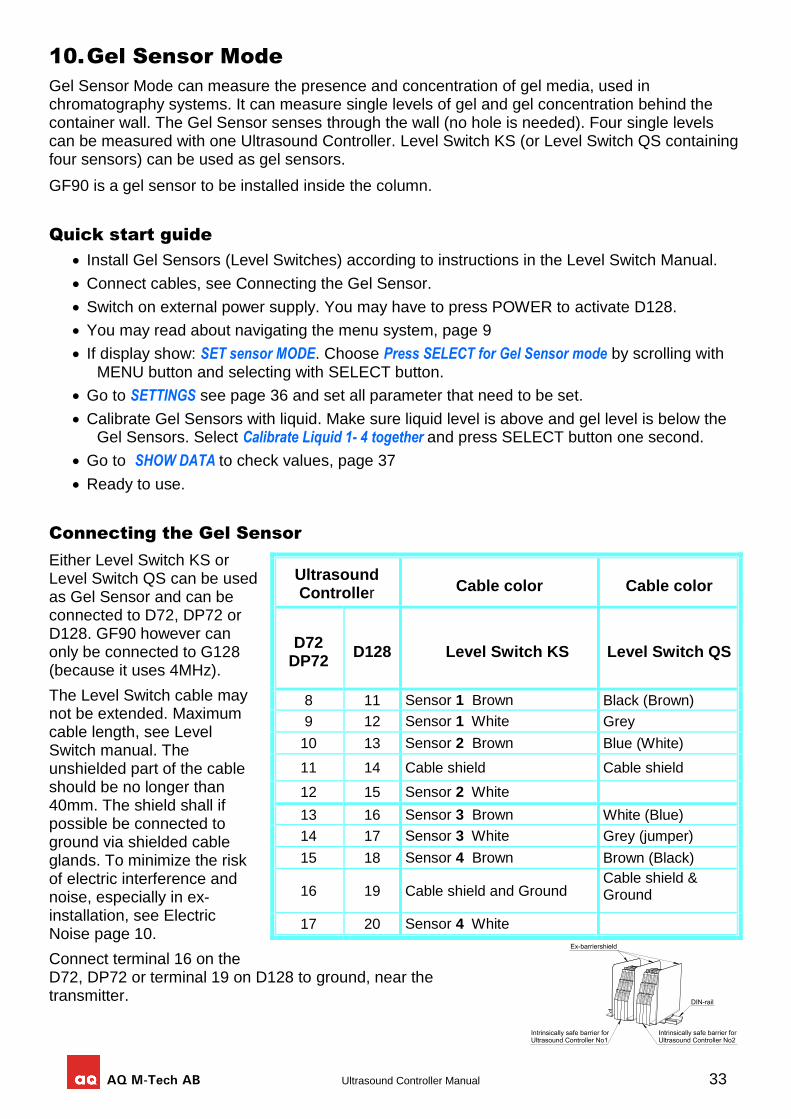
AQ M-Tech AB Ultrasound Controller Manual 33
10. Gel Sensor Mode
Gel Sensor Mode can measure the presence and concentration of gel media, used in chromatography systems. It can measure single levels of gel and gel concentration behind the container wall. The Gel Sensor senses through the wall (no hole is needed). Four single levels can be measured with one Ultrasound Controller. Level Switch KS (or Level Switch QS containing four sensors) can be used as gel sensors.
GF90 is a gel sensor to be installed inside the column.
Quick start guide
Install Gel Sensors (Level Switches) according to instructions in the Level Switch Manual.
Connect cables, see Connecting the Gel Sensor.
Switch on external power supply. You may have to press POWER to activate D128.
You may read about navigating the menu system, page 9
If display show: SET sensor MODE. Choose Press SELECT for Gel Sensor mode by scrolling with MENU button and selecting with SELECT button.
Go to SETTINGS see page 36 and set all parameter that need to be set.
Calibrate Gel Sensors with liquid. Make sure liquid level is above and gel level is below the Gel Sensors. Select Calibrate Liquid 1- 4 together and press SELECT button one second.
Go to SHOW DATA to check values, page 37
Ready to use.
Connecting the Gel Sensor
Either Level Switch KS or Level Switch QS can be used as Gel Sensor and can be connected to D72, DP72 or D128. GF90 however can only be connected to G128 (because it uses 4MHz).
The Level Switch cable may not be extended. Maximum cable length, see Level Switch manual. The unshielded part of the cable should be no longer than 40mm. The shield shall if possible be connected to ground via shielded cable glands. To minimize the risk of electric interference and noise, especially in ex-installation, see Electric Noise page 10.
Connect terminal 16 on the D72, DP72 or terminal 19 on D128 to ground, near the transmitter.
Ultrasound Controller
Terminal
Cable color Cable color
D72 DP72
D128 Level Switch KS Level Switch QS
8 11 Sensor 1 Brown Black (Brown)
9 12 Sensor 1 White Grey
10 13 Sensor 2 Brown Blue (White)
11 14 Cable shield Cable shield
12 15 Sensor 2 White
13 16 Sensor 3 Brown White (Blue)
14 17 Sensor 3 White Grey (jumper)
15 18 Sensor 4 Brown Brown (Black)
16 19 Cable shield and Ground Cable shield & Ground
17 20 Sensor 4 White
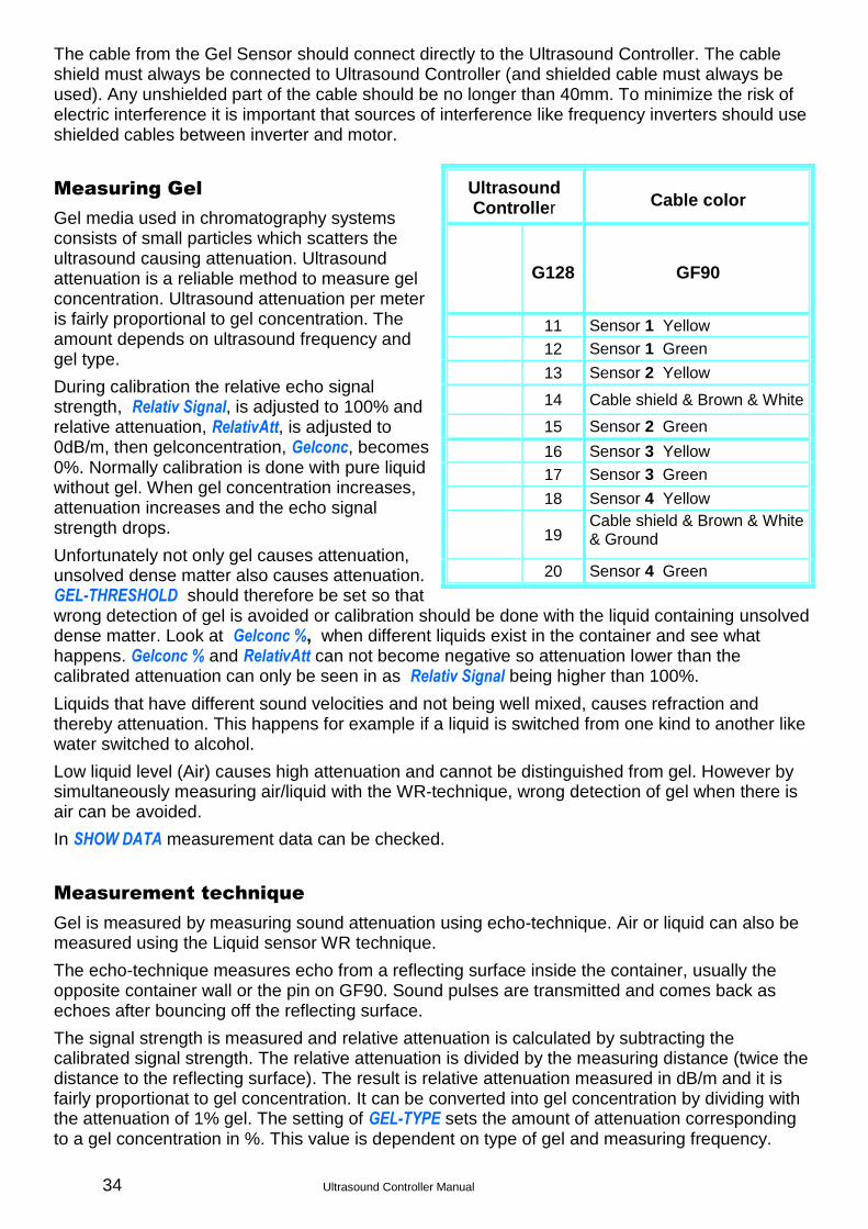
34 Ultrasound Controller Manual
The cable from the Gel Sensor should connect directly to the Ultrasound Controller. The cable shield must always be connected to Ultrasound Controller (and shielded cable must always be used). Any unshielded part of the cable should be no longer than 40mm. To minimize the risk of electric interference it is important that sources of interference like frequency inverters should use shielded cables between inverter and motor.
Measuring Gel
Gel media used in chromatography systems consists of small particles which scatters the ultrasound causing attenuation. Ultrasound attenuation is a reliable method to measure gel concentration. Ultrasound attenuation per meter is fairly proportional to gel concentration. The amount depends on ultrasound frequency and gel type.
During calibration the relative echo signal strength, Relativ Signal, is adjusted to 100% and relative attenuation, RelativAtt, is adjusted to 0dB/m, then gelconcentration, Gelconc, becomes 0%. Normally calibration is done with pure liquid without gel. When gel concentration increases, attenuation increases and the echo signal strength drops.
Unfortunately not only gel causes attenuation, unsolved dense matter also causes attenuation. GEL-THRESHOLD should therefore be set so that wrong detection of gel is avoided or calibration should be done with the liquid containing unsolved dense matter. Look at Gelconc %, when different liquids exist in the container and see what happens. Gelconc % and RelativAtt can not become negative so attenuation lower than the calibrated attenuation can only be seen in as Relativ Signal being higher than 100%.
Liquids that have different sound velocities and not being well mixed, causes refraction and thereby attenuation. This happens for example if a liquid is switched from one kind to another like water switched to alcohol.
Low liquid level (Air) causes high attenuation and cannot be distinguished from gel. However by simultaneously measuring air/liquid with the WR-technique, wrong detection of gel when there is air can be avoided.
In SHOW DATA measurement data can be checked.
Measurement technique
Gel is measured by measuring sound attenuation using echo-technique. Air or liquid can also be measured using the Liquid sensor WR technique.
The echo-technique measures echo from a reflecting surface inside the container, usually the opposite container wall or the pin on GF90. Sound pulses are transmitted and comes back as echoes after bouncing off the reflecting surface.
The signal strength is measured and relative attenuation is calculated by subtracting the calibrated signal strength. The relative attenuation is divided by the measuring distance (twice the distance to the reflecting surface). The result is relative attenuation measured in dB/m and it is fairly proportionat to gel concentration. It can be converted into gel concentration by dividing with the attenuation of 1% gel. The setting of GEL-TYPE sets the amount of attenuation corresponding to a gel concentration in %. This value is dependent on type of gel and measuring frequency.
Ultrasound Controller
Terminal
Cable color
G128 GF90
11 Sensor 1 Yellow
12 Sensor 1 Green
13 Sensor 2 Yellow
14 Cable shield & Brown & White
15 Sensor 2 Green
16 Sensor 3 Yellow
17 Sensor 3 Green
18 Sensor 4 Yellow
19 Cable shield & Brown & White & Ground
20 Sensor 4 Green
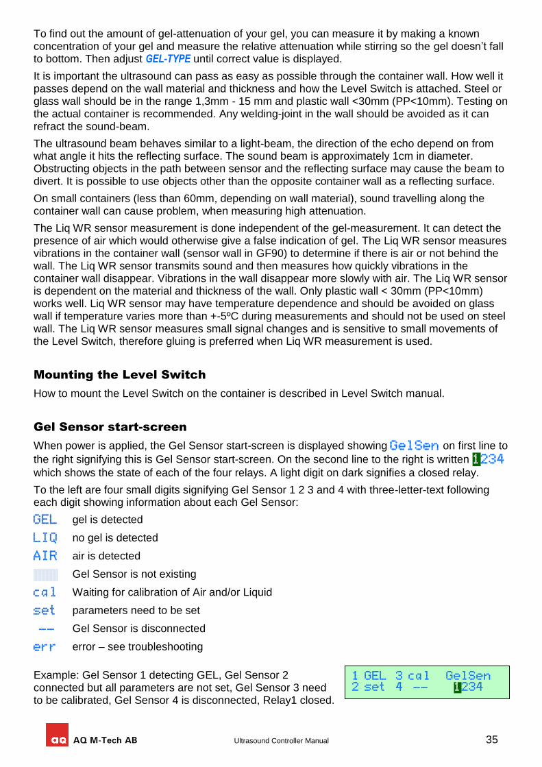
AQ M-Tech AB Ultrasound Controller Manual 35
To find out the amount of gel-attenuation of your gel, you can measure it by making a known concentration of your gel and measure the relative attenuation while stirring so the gel doesn’t fall to bottom. Then adjust GEL-TYPE until correct value is displayed.
It is important the ultrasound can pass as easy as possible through the container wall. How well it passes depend on the wall material and thickness and how the Level Switch is attached. Steel or glass wall should be in the range 1,3mm - 15 mm and plastic wall <30mm (PP<10mm). Testing on the actual container is recommended. Any welding-joint in the wall should be avoided as it can refract the sound-beam.
The ultrasound beam behaves similar to a light-beam, the direction of the echo depend on from what angle it hits the reflecting surface. The sound beam is approximately 1cm in diameter. Obstructing objects in the path between sensor and the reflecting surface may cause the beam to divert. It is possible to use objects other than the opposite container wall as a reflecting surface.
On small containers (less than 60mm, depending on wall material), sound travelling along the container wall can cause problem, when measuring high attenuation.
The Liq WR sensor measurement is done independent of the gel-measurement. It can detect the presence of air which would otherwise give a false indication of gel. The Liq WR sensor measures vibrations in the container wall (sensor wall in GF90) to determine if there is air or not behind the wall. The Liq WR sensor transmits sound and then measures how quickly vibrations in the container wall disappear. Vibrations in the wall disappear more slowly with air. The Liq WR sensor is dependent on the material and thickness of the wall. Only plastic wall < 30mm (PP<10mm) works well. Liq WR sensor may have temperature dependence and should be avoided on glass wall if temperature varies more than +-5ºC during measurements and should not be used on steel wall. The Liq WR sensor measures small signal changes and is sensitive to small movements of the Level Switch, therefore gluing is preferred when Liq WR measurement is used.
Mounting the Level Switch
How to mount the Level Switch on the container is described in Level Switch manual.
Gel Sensor start-screen
When power is applied, the Gel Sensor start-screen is displayed showing GelSen on first line to
the right signifying this is Gel Sensor start-screen. On the second line to the right is written 1234
which shows the state of each of the four relays. A light digit on dark signifies a closed relay.
To the left are four small digits signifying Gel Sensor 1 2 3 and 4 with three-letter-text following each digit showing information about each Gel Sensor:
GEL gel is detected
LIQ no gel is detected
AIR air is detected
™™™ Gel Sensor is not existing
cal Waiting for calibration of Air and/or Liquid
set parameters need to be set
-- Gel Sensor is disconnected
err error – see troubleshooting
Example: Gel Sensor 1 detecting GEL, Gel Sensor 2 connected but all parameters are not set, Gel Sensor 3 need to be calibrated, Gel Sensor 4 is disconnected, Relay1 closed.
1 GEL 3 cal GelSen 2 set 4 -- 1234
36 Ultrasound Controller Manual
SETTINGS
Through the SETTINGS-menu the parameters of the Gel Sensor can be set.
Select SET Type to set it according to how many sensors are connected, or set to Level Switch QS. For GF90 set it to GS1 if one is connected and GS1,GS2 if two are connected and so on.
Select SET ECHO-DISTANCE to set the distance between the Level Switch and opposite reflecting surface inside the container. For GF90 set it to 90mm.
Select SET GEL-TYPE to set the the amount of attenuation of the gel (depend on gel type and frequency) For Streamline SP gel set to: 7dB/m at 2MHz,14dB/m at 4MHz for tungsten gel set to: 40dB/m at 2MHz,80dB/m at 4MHz.
Select SET GEL-THRESHOLD to set the gel concentration to be detected. Gel-threshold is independent of ECHO-DISTANCE. Depending also on ECHO-DISTANCE and GEL-TYPE coprrespond to an attenuation. Be careful with high setting of GEL-THRESHOLD at long ECHO-DISTANCE since high attenuation can be difficult to measure.
Select SET FREQUENCY to set the measurement frequency. Calibration for different frequencies are stored during calibration. FREQUENCY can be changed after calibration. If container is made of glass or stainless steel, try different frequencies to find one with strongest echo. (The wall thickness determines how well different frequencies can pass the wall). For GF90 set it to 4MHz.
Select Liquid Sensor SET WR THRESHOLD to set threshold of the Liq WR sensor. A good setting is half the value of Liq WR sensor dB with Air (see SHOW DATA). It works best on plastic wall or GF90. For GF90 it can be set to 7dB. If not used set it to disabled.
Select SET RELAY to set how the relays act. Each relay has one contact (at power off the relay is open). There are four relays. Relay can be set to be closed or open with detection of gel. If Liq WR sensor is used and detecting air, this prevents indicating gel. Relay can also be set to be closed with air, with no sensor or with error.
Select SET mA output A or SET mA output B to set the 4-20mA outputs. 1,5mA/GelDetectn means each gel sensor that detects gel adds 1,5mA to the output. Relative attenu. 1mA=-4dB/m means output is 1mA for each 4dB/m of attenuation. Gelconcentration 1mA=1% means output is proportional to gelconcentration: 0% = 4mA, 16% = 20mA. If Liq WR sensor is used and it detects air, gelconcentration will be zero.
CALIBRATION
Make sure there is liquid and no gel behind the Level Switches. Select CALIBRATION and select 1-4 together (or select a single sensor) then hold SELECT button pressed one second to calibrate the Gel Sensors.
The sensors must be calibrated after installation. If the KS or QS sensors have been moved it is recommended to calibrate again. Changing the ECHO-DISTANCE also require new calibration.
To see how well the Gel Sensor behaves with different liquids the relative echo signal can be checked in SHOW DATA. Look at the values in Relativ Signal % and Gelconc. Check how different liquids affect the echo signal.
If Liquid Sensor WR is not disabled check also Liq WR sensor dB. This is the signal from the Liquid Sensor WR which is set to zero during calibration. With air in the container check the value of Liq WR sensor dB. The Liquid Sensor WR THRESHOLD should be set to half of this value.
Check Signal Strength. With liquid and no gel it should be minimum 35dB. The reason for a low signal strength can be a tiny air-gap between the Level Switch and the container, wrong angled Level Switch, wrong settings, liquid that attenuates the sound, glass or steel wall with thickness that do not let through the selected frequency very well (try a different frequency).
AQ M-Tech AB Ultrasound Controller Manual 37
SHOW DATA
Select Measured data to show measured data. All four Gel Sensors are shown together. Pressing MENU button scrolls through: Gelconc. %, Relativ Signal %, RelativAtt. dB/m, Signal dB and Liq WR sensor dB.
Gelconc. %, is the measured gel concentration.
Reltiv Signal %, is measured echo signal strength in percent of calibrated echo signal strength.
RelativAtt. dB/m, is the measured sound attenuation per meter. It is set to zero at calibration and it is independent of echo-distance.
Signal dB is the measured echo signal strength (dB) where 85dB is maximum and 0dB is minimum. When signal is below 20dB, then echo is so weak that there is risk that the measured gel-concentration is lower than actual gel-concentration.
Liq WR sensor dB is the signal from the WR-measurement (determining if there is liquid or air) and it is shown relative to signal strength at calibration (dB). It is adjusted to 0dB with liquid during calibration and depending on the container wall around 3dB with air. Check this with liquid and with air to determine the value for WR THRESHOLD.
Select Calibrated Data to show calibrated data. All four Gel Sensors are shown together. Pressing MENU button scrolls through: Cal Liq dB, Freq and Test Sensor dB
Cal Liq dB is the measured echo signal strength during calibration with liquid (dB). The higher the better. Lower than 35dB is considered to be too weak signal.
Freq is the chosen frequency: 1=1,3MHz, 2=1,5MHz, 3=1,7MHz, 4=2MHz, 5=2,2MHz or 6=4MHz. Use as high as possible (except only GF90 uses 4MHz). Steel or glass wall thickness may make it necessary to change to a lower frequency in order to get high echo strength.
Test Sensor dB shows Liquid Sensor WR signal. It can be used to test a Gel Sensor not attached to a container. If the Gel Sensor is correctly connected a value between 0 and 30 should be shown. Pressing on the inner side of the Gel Sensor with a thumb the value increases showing the Level Switch is working. A bad Level Switch, wrong or not connected will show a value 60 or more.
ADVANCED SETTINGS
Select Set sensor MODE to set either Air Sensor mode, Level Switch mode, Level Sensor mode or Gel Sensor mode mode. It determines which sensor can be connected.
Select RESTORE settings and calibrations to restore all settings and calibrations to factory-settings.
Select PROFIBUS SETTINGS see page 39 (for DP72).
HELP
Select HELP to show information about connecting the Ultrasound Controller.
Measurement Reliability
Many factors determine the reliability (wall material, wall thickness, liquid properties, temperature and glue). Therefore it is always advisable to make tests under varying conditions and temperatures.
The reliability of Liquid Sensor WR depend on the container wall. On a plastic wall 10-30mm it works well. On GF90 it works well. On a glass wall and polypropylene wall there can be temperature dependence and should not be used if there is more than +- 7°C variation during measurement. On steel wall it is not recommended.
38 Ultrasound Controller Manual
Gel Sensor TROUBLESHOOTING
Display shows: -- The Gel Sensor is not connected or there is a short circuit. cal Calibration has not been done. Calibration must be done with Liquid. set Some settings are missing. If the relay does not change but the display changes between
Liquid, Air and Gel then setting of RELAY is wrong. err During calibration the echo signal was weak: The reason can be: Calibration was done
without liquid or with gel. Or the Level Switch is not attached correctly to the container. There is a tiny air-gap between the Level Switch and the container. Or DISTANCE to reflecting wall is set wrong. Or the echo is reflected in a direction where it does not reach the Level Switch. Or something obstructing lies between the Level Switch and the reflecting wall. Or the container wall does not let through enough sound. Try a different FREQUENCY. Or wrong connection or faulty Level Switch. Select Test Gel Sensor then test the Level Switch and its connection.
Electric interference can show itself as the attenuation and gel concentration not being able to get high enough with gel. To minimize the risk of interference it is important that sources of interference (like frequency inverters) should use shielded cables between inverter and motor. Also any unshielded part of the cable between the Level Switch and Ultrasound Controller should be short. If ex-barriers are used, Ex-barriershields must be used especially if there is more than one Ultrasound Controller.
AQ M-Tech AB Ultrasound Controller Manual 39
11. Profibus DP
Connecting Profibus
The Ultrasound Controller DP72,GP72 supports Profibus DP-V0 with communication speeds up to 1,5Mbit/s. The Profibus cable connects to DP72,GP72 via a 9-pin D-sub connector see table.
To terminate the Profibus cable, put 390Ω between pin6 and pin8 and 220Ω between pin6 and pin5 and 390Ω between pin3 and pin5.
The Profibus-interface in DP72,GP72 is not isolated from power supply.
The gsd-file: DP720B0E.gsd is needed for configuration of the Profibus master. It can be downloaded at www.aqmtech.se. The version of the gsd-file is written in the beginning of the gsd-file (the gsd-file can be viewed with a text editor). It must be the correct version. See page 3 for correct version.
PROFIBUS Parameters
The PROFIBUS SETTING menu: (accessible through ADVANCED SETTINGS menu)
Select BITRATE: to set the bitrate. Auto automatically selects bitrate. (Maximum bitrate is 1,5Mbit/s).
Select ADDRESS: to set the address (0-125). Every unit must have different address.
Select PARAMETER ACCESS. If set to Profibus only then all parameters, (except PROFIBUS Parameters) will be set by the Profibus master only. If set to Menu only, then all parameters can be set via the menu and not via Profibus master.
Select CONTROL: to Enabled or Disabled Profibus communication.
Profibus Status-symbol
The status of the Profibus communication is shown as a Profibus status-symbol on the start screen at the bottom right corner of the display:
□ Profibus enabled but no communication is detected.
™ (nothing) Profibus is not enabled.
█ Communication is detected.
T Correct profibus telegrams detected.
P Parameter or configuration telegram received.
> < (alternating) Data exchange. (Data is received and responded)
X Ready for data exchange but no data telegram is being received.
Request Data
In data exchange state the master regularly sends one byte request data and DP72 responds with 16 bytes response data (1-16).
Request data should be normally zero. The master can start calibration of one or more sensors by sending request data with calibration command (the request data bits 1-4 are set according to which sensors are to be calibrated and bit0 is set if liquid is to be calibrated, see the Profibus data exchange table below). After the master has sent this request data with calibration command, request data should be cleared to zero again. DP72 starts the calibration exactly when request data bit 1-4 changes from being all zero to being non-zero. Calibration can also be done through
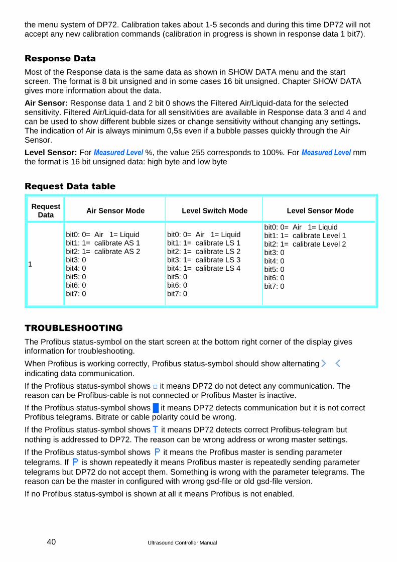
40 Ultrasound Controller Manual
the menu system of DP72. Calibration takes about 1-5 seconds and during this time DP72 will not accept any new calibration commands (calibration in progress is shown in response data 1 bit7).
Response Data
Most of the Response data is the same data as shown in SHOW DATA menu and the start screen. The format is 8 bit unsigned and in some cases 16 bit unsigned. Chapter SHOW DATA gives more information about the data.
Air Sensor: Response data 1 and 2 bit 0 shows the Filtered Air/Liquid-data for the selected sensitivity. Filtered Air/Liquid-data for all sensitivities are available in Response data 3 and 4 and can be used to show different bubble sizes or change sensitivity without changing any settings. The indication of Air is always minimum 0,5s even if a bubble passes quickly through the Air Sensor.
Level Sensor: For Measured Level %, the value 255 corresponds to 100%. For Measured Level mm the format is 16 bit unsigned data: high byte and low byte
Request Data table
TROUBLESHOOTING
The Profibus status-symbol on the start screen at the bottom right corner of the display gives information for troubleshooting.
When Profibus is working correctly, Profibus status-symbol should show alternating > < indicating data communication.
If the Profibus status-symbol shows □ it means DP72 do not detect any communication. The reason can be Profibus-cable is not connected or Profibus Master is inactive.
If the Profibus status-symbol shows █ it means DP72 detects communication but it is not correct Profibus telegrams. Bitrate or cable polarity could be wrong.
If the Profibus status-symbol shows T it means DP72 detects correct Profibus-telegram but
nothing is addressed to DP72. The reason can be wrong address or wrong master settings.
If the Profibus status-symbol shows P it means the Profibus master is sending parameter
telegrams. If P is shown repeatedly it means Profibus master is repeatedly sending parameter
telegrams but DP72 do not accept them. Something is wrong with the parameter telegrams. The reason can be the master in configured with wrong gsd-file or old gsd-file version.
If no Profibus status-symbol is shown at all it means Profibus is not enabled.
Request Data
Air Sensor Mode Level Switch Mode Level Sensor Mode
1
bit0: 0= Air 1= Liquid bit1: 1= calibrate AS 1 bit2: 1= calibrate AS 2 bit3: 0 bit4: 0 bit5: 0 bit6: 0 bit7: 0
bit0: 0= Air 1= Liquid bit1: 1= calibrate LS 1 bit2: 1= calibrate LS 2 bit3: 1= calibrate LS 3 bit4: 1= calibrate LS 4 bit5: 0 bit6: 0 bit7: 0
bit0: 0= Air 1= Liquid bit1: 1= calibrate Level 1 bit2: 1= calibrate Level 2 bit3: 0 bit4: 0 bit5: 0 bit6: 0 bit7: 0
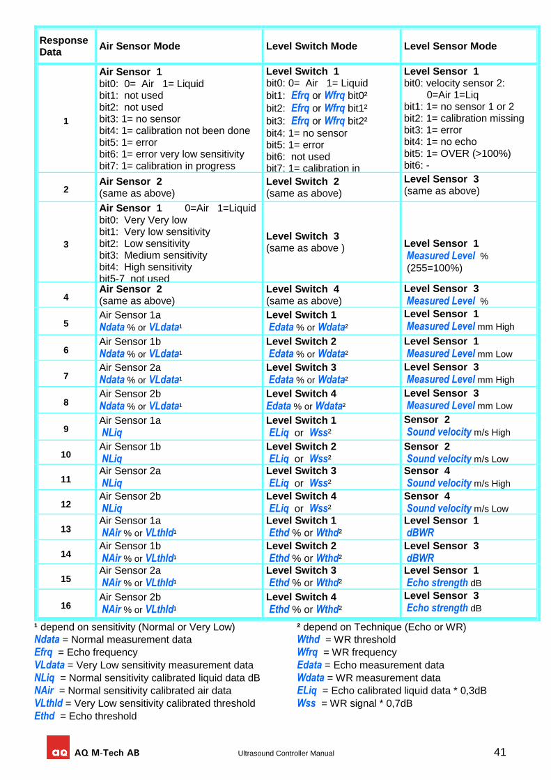
AQ M-Tech AB Ultrasound Controller Manual 41
¹ depend on sensitivity (Normal or Very Low) ² depend on Technique (Echo or WR)
Ndata = Normal measurement data Wthd = WR threshold
Efrq = Echo frequency Wfrq = WR frequency
VLdata = Very Low sensitivity measurement data Edata = Echo measurement data
NLiq = Normal sensitivity calibrated liquid data dB Wdata = WR measurement data
NAir = Normal sensitivity calibrated air data ELiq = Echo calibrated liquid data * 0,3dB
VLthld = Very Low sensitivity calibrated threshold Wss = WR signal * 0,7dB Ethd = Echo threshold
Response Data
Air Sensor Mode Level Switch Mode Level Sensor Mode
1
Air Sensor 1 bit0: 0= Air 1= Liquid bit1: not used bit2: not used bit3: 1= no sensor bit4: 1= calibration not been done bit5: 1= error bit6: 1= error very low sensitivity bit7: 1= calibration in progress
Level Switch 1 bit0: 0= Air 1= Liquid
bit1: Efrq or Wfrq bit0²
bit2: Efrq or Wfrq bit1²
bit3: Efrq or Wfrq bit2²
bit4: 1= no sensor bit5: 1= error bit6: not used bit7: 1= calibration in progress
Level Sensor 1 bit0: velocity sensor 2: 0=Air 1=Liq bit1: 1= no sensor 1 or 2 bit2: 1= calibration missing bit3: 1= error bit4: 1= no echo bit5: 1= OVER (>100%) bit6: - bit7: -
2 Air Sensor 2 (same as above)
Level Switch 2 (same as above)
Level Sensor 3 (same as above)
3
Air Sensor 1 0=Air 1=Liquid bit0: Very Very low bit1: Very low sensitivity bit2: Low sensitivity bit3: Medium sensitivity bit4: High sensitivity bit5-7 not used
Level Switch 3 (same as above )
Level Sensor 1
Measured Level %
(255=100%)
4 Air Sensor 2 (same as above)
Level Switch 4 (same as above)
Level Sensor 3
Measured Level %
5 Air Sensor 1a
Ndata % or VLdata¹
Level Switch 1
Edata % or Wdata²
Level Sensor 1
Measured Level mm High
6 Air Sensor 1b
Ndata % or VLdata¹
Level Switch 2
Edata % or Wdata²
Level Sensor 1
Measured Level mm Low
7 Air Sensor 2a
Ndata % or VLdata¹
Level Switch 3
Edata % or Wdata²
Level Sensor 3
Measured Level mm High
8 Air Sensor 2b
Ndata % or VLdata¹
Level Switch 4
Edata % or Wdata²
Level Sensor 3
Measured Level mm Low
9 Air Sensor 1a NLiq
Level Switch 1
ELiq or Wss²
Sensor 2
Sound velocity m/s High
10 Air Sensor 1b
NLiq
Level Switch 2
ELiq or Wss²
Sensor 2
Sound velocity m/s Low
11 Air Sensor 2a
NLiq
Level Switch 3
ELiq or Wss²
Sensor 4
Sound velocity m/s High
12 Air Sensor 2b
NLiq
Level Switch 4
ELiq or Wss²
Sensor 4
Sound velocity m/s Low
13 Air Sensor 1a
NAir % or VLthld¹
Level Switch 1
Ethd % or Wthd²
Level Sensor 1
dBWR
14 Air Sensor 1b
NAir % or VLthld¹
Level Switch 2
Ethd % or Wthd²
Level Sensor 3
dBWR
15 Air Sensor 2a
NAir % or VLthld¹
Level Switch 3
Ethd % or Wthd²
Level Sensor 1
Echo strength dB
16 Air Sensor 2b
NAir % or VLthld¹
Level Switch 4
Ethd % or Wthd²
Level Sensor 3
Echo strength dB
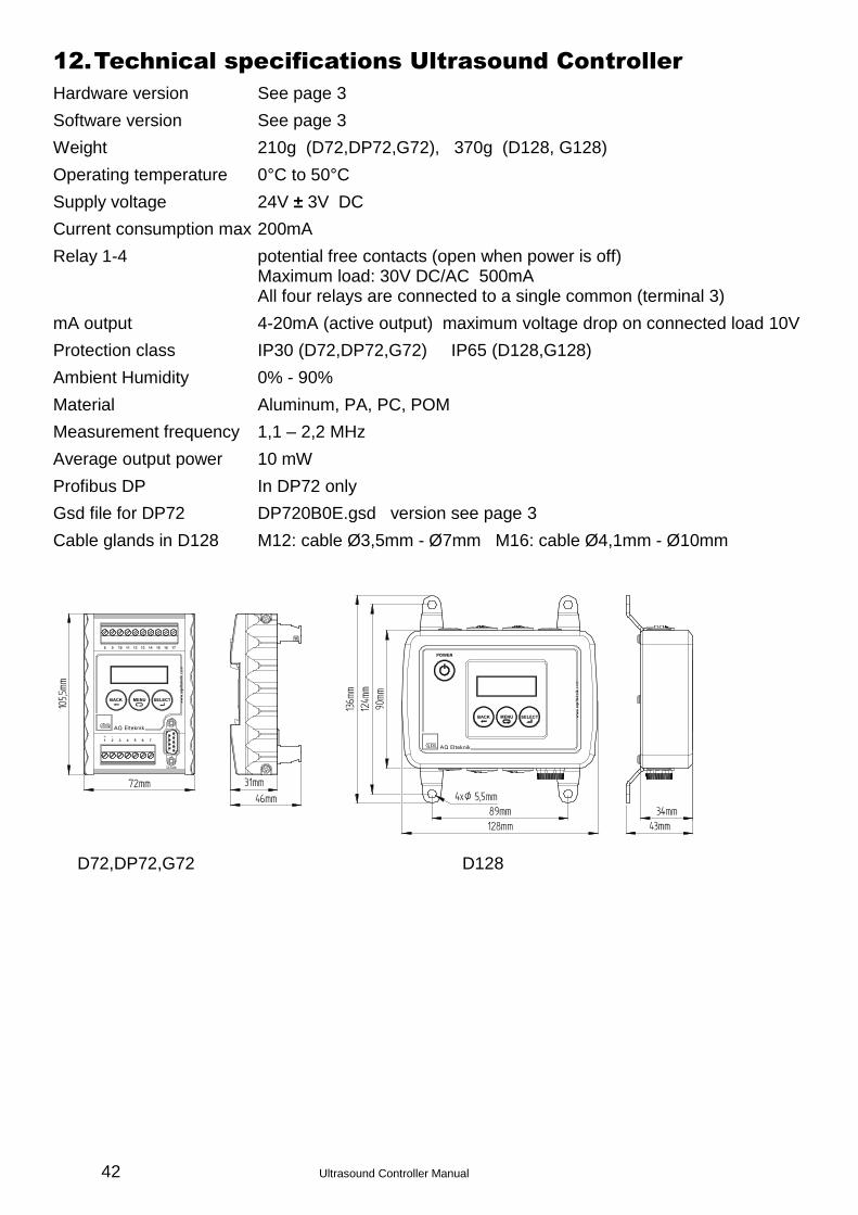
42 Ultrasound Controller Manual
12. Technical specifications Ultrasound Controller
Hardware version See page 3
Software version See page 3
Weight 210g (D72,DP72,G72), 370g (D128, G128)
Operating temperature 0°C to 50°C
Supply voltage 24V ± 3V DC
Current consumption max 200mA
Relay 1-4 potential free contacts (open when power is off) Maximum load: 30V DC/AC 500mA All four relays are connected to a single common (terminal 3)
mA output 4-20mA (active output) maximum voltage drop on connected load 10V
Protection class IP30 (D72,DP72,G72) IP65 (D128,G128)
Ambient Humidity 0% - 90%
Material Aluminum, PA, PC, POM
Measurement frequency 1,1 – 2,2 MHz
Average output power 10 mW
Profibus DP In DP72 only
Gsd file for DP72 DP720B0E.gsd version see page 3
Cable glands in D128 M12: cable Ø3,5mm - Ø7mm M16: cable Ø4,1mm - Ø10mm
D72,DP72,G72 D128
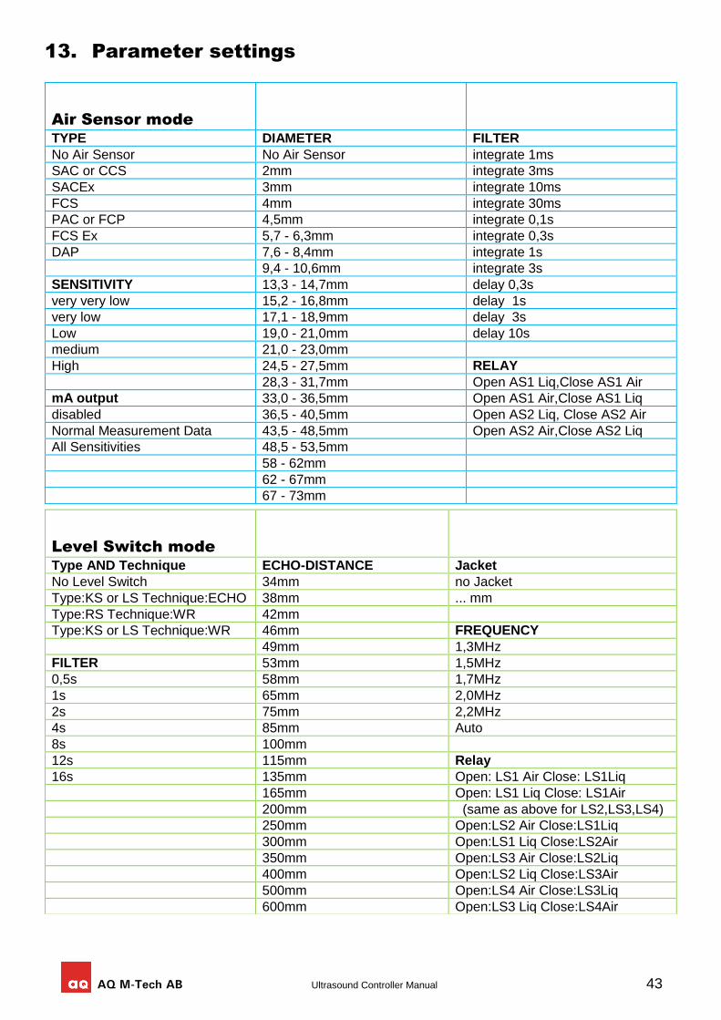
AQ M-Tech AB Ultrasound Controller Manual 43
13. Parameter settings
Air Sensor mode
TYPE DIAMETER FILTER
No Air Sensor No Air Sensor integrate 1ms
SAC or CCS 2mm integrate 3ms
SACEx 3mm integrate 10ms
FCS 4mm integrate 30ms
PAC or FCP 4,5mm integrate 0,1s
FCS Ex 5,7 - 6,3mm integrate 0,3s
DAP 7,6 - 8,4mm integrate 1s
9,4 - 10,6mm integrate 3s
SENSITIVITY 13,3 - 14,7mm delay 0,3s
very very low 15,2 - 16,8mm delay 1s
very low 17,1 - 18,9mm delay 3s
Low 19,0 - 21,0mm delay 10s
medium 21,0 - 23,0mm
High 24,5 - 27,5mm RELAY
28,3 - 31,7mm Open AS1 Liq,Close AS1 Air
mA output 33,0 - 36,5mm Open AS1 Air,Close AS1 Liq
disabled 36,5 - 40,5mm Open AS2 Liq, Close AS2 Air
Normal Measurement Data 43,5 - 48,5mm Open AS2 Air,Close AS2 Liq
All Sensitivities 48,5 - 53,5mm
58 - 62mm
62 - 67mm
67 - 73mm
Level Switch mode
Type AND Technique ECHO-DISTANCE Jacket
No Level Switch 34mm no Jacket
Type:KS or LS Technique:ECHO 38mm ... mm
Type:RS Technique:WR 42mm
Type:KS or LS Technique:WR 46mm FREQUENCY
49mm 1,3MHz
FILTER 53mm 1,5MHz
0,5s 58mm 1,7MHz
1s 65mm 2,0MHz
2s 75mm 2,2MHz
4s 85mm Auto
8s 100mm
12s 115mm Relay
16s 135mm Open: LS1 Air Close: LS1Liq
165mm Open: LS1 Liq Close: LS1Air
200mm (same as above for LS2,LS3,LS4)
250mm Open:LS2 Air Close:LS1Liq
300mm Open:LS1 Liq Close:LS2Air
350mm Open:LS3 Air Close:LS2Liq
400mm Open:LS2 Liq Close:LS3Air
500mm Open:LS4 Air Close:LS3Liq
600mm Open:LS3 Liq Close:LS4Air
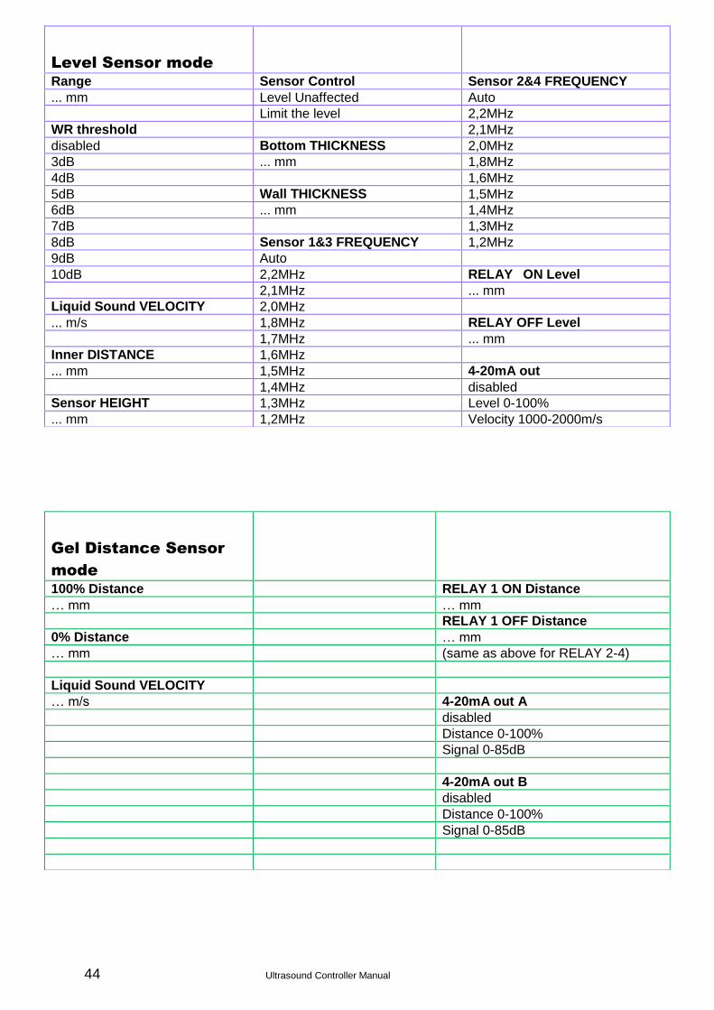
44 Ultrasound Controller Manual
Level Sensor mode
Range Sensor Control Sensor 2&4 FREQUENCY
... mm Level Unaffected Auto
Limit the level 2,2MHz
WR threshold 2,1MHz
disabled Bottom THICKNESS 2,0MHz
3dB ... mm 1,8MHz
4dB 1,6MHz
5dB Wall THICKNESS 1,5MHz
6dB ... mm 1,4MHz
7dB 1,3MHz
8dB Sensor 1&3 FREQUENCY 1,2MHz
9dB Auto
10dB 2,2MHz RELAY ON Level
2,1MHz ... mm
Liquid Sound VELOCITY 2,0MHz
... m/s 1,8MHz RELAY OFF Level
1,7MHz ... mm
Inner DISTANCE 1,6MHz
... mm 1,5MHz 4-20mA out
1,4MHz disabled
Sensor HEIGHT 1,3MHz Level 0-100%
... mm 1,2MHz Velocity 1000-2000m/s
Gel Distance Sensor
mode
100% Distance RELAY 1 ON Distance
… mm … mm
RELAY 1 OFF Distance
0% Distance … mm
… mm (same as above for RELAY 2-4)
Liquid Sound VELOCITY
… m/s 4-20mA out A
disabled
Distance 0-100%
Signal 0-85dB
4-20mA out B
disabled
Distance 0-100%
Signal 0-85dB
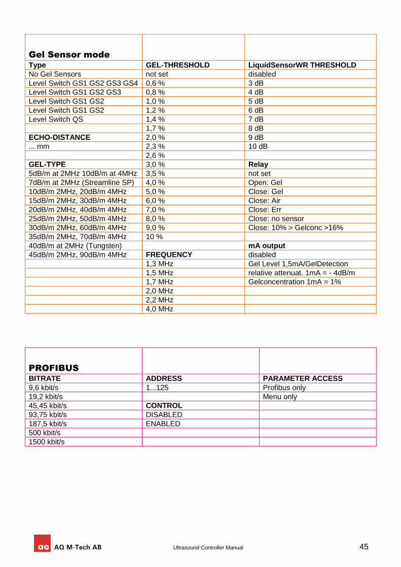
AQ M-Tech AB Ultrasound Controller Manual 45
Gel Sensor mode
Type GEL-THRESHOLD LiquidSensorWR THRESHOLD
No Gel Sensors not set disabled
Level Switch GS1 GS2 GS3 GS4 0,6 % 3 dB
Level Switch GS1 GS2 GS3 0,8 % 4 dB
Level Switch GS1 GS2 1,0 % 5 dB
Level Switch GS1 GS2 1,2 % 6 dB
Level Switch QS 1,4 % 7 dB
1,7 % 8 dB
ECHO-DISTANCE 2,0 % 9 dB
... mm 2,3 % 10 dB
2,6 %
GEL-TYPE 3,0 % Relay
5dB/m at 2MHz 10dB/m at 4MHz 3,5 % not set
7dB/m at 2MHz (Streamline SP) 4,0 % Open: Gel
10dB/m 2MHz, 20dB/m 4MHz 5,0 % Close: Gel
15dB/m 2MHz, 30dB/m 4MHz 6,0 % Close: Air
20dB/m 2MHz, 40dB/m 4MHz 7,0 % Close: Err
25dB/m 2MHz, 50dB/m 4MHz 8,0 % Close: no sensor
30dB/m 2MHz, 60dB/m 4MHz 9,0 % Close: 10% > Gelconc >16%
35dB/m 2MHz, 70dB/m 4MHz 10 %
40dB/m at 2MHz (Tungsten) mA output
45dB/m 2MHz, 90dB/m 4MHz FREQUENCY disabled
1,3 MHz Gel Level 1,5mA/GelDetection
1,5 MHz relative attenuat. 1mA = - 4dB/m
1,7 MHz Gelconcentration 1mA = 1%
2,0 MHz
2,2 MHz
4,0 MHz
PROFIBUS
BITRATE ADDRESS PARAMETER ACCESS
9,6 kbit/s 1...125 Profibus only
19,2 kbit/s Menu only
45,45 kbit/s CONTROL
93,75 kbit/s DISABLED
187,5 kbit/s ENABLED
500 kbit/s
1500 kbit/s
46 Ultrasound Controller Manual
14. Hardware and Software Version History
D72RevE and DP72RevE and D128RevA and G72RevA
Version 5.21 May 2017 Support for Air Sensor DAP. Diameter range for Air Sensor has been extended. Gel Distance Mode minor bugfixes.
Version 5.16 March 2017 Ground connection recommendation to terminal 16 or 19 to avoid electric noise.
Version 5.10 February 2017 Air Sensor parameter diameter becomes a diameter-interval.
Version 5.09 December 2016 All 4-20mA outputs gets increased accuracy. LevelSensor: parameter change name from 100%Level to Range. Offset parameter is added.
Version 5.08 September 2016 GelSensor: Bugfix. Relay settings changed. WR THRESHOLD changed values. New calibration for 4MHz versions. LevelSensor: improvements.
Version 5.06 August 2016 POWER switch in D128 and G128 to be pressed 4 seconds to enter standby. Level Sensor calibration is faster. 4-20mA improved accuracy. Profibus AUTO bitrate bugfix (in 5.02).
Version 5.02 June 2016 Profibus AUTO bitrate was too slow, now it has become faster finding correct bitrate.
Version 5.01 - March 2016 Level Sensor mode: The noise-filter is improved. An additional WR-technique measurement is added to improve measuring levels below 20mm and empty container. No Sensor detection is added. Parameters has been changed so there is a new GSD-file.
Version 4.92 - November 2015 Gel Distance mode is added, available in G72 only.
Version 4.91 - October 2015 Level Sensor mode: show level in % instead of mm on the start-screen. No asking for calibration after change of parameters for the velocity sensor (to make possible for small adjustments of diameter). Three error messages: err1 err2 err3 instead of one single err. The sensors are named Sensor 1, Sensor 2, Sensor 3, Sensor 4 instead of LV1, VS1, LV2, VS2. Bugfix on sensor 3 and 4. Changes in how measurements and calibration values are displayed in SHOW DATA for Level Sensor. Increased accuracy in measurements.
Version 4.82 - September 2015 Air Sensor: Increased threshold for detecting connected sensor (FSC10Ex with barrier sometimes was not recognized before)
Version 4.81 - July 2015 Profibus is available for Gel Sensor mode. New GDS-file for profibus: GDS 3.3 which also includes GelSensor mode. FCP4 and FCP6 internal parameters for predelay and measuretime is changed to improve measurements. LevelSwitch: FILTER parameters gives more accurate filter time constants.
Version 4.71 - April 2015 Air Sensor: when a sensor is disconnected the corresponding relay disengages regardless of the relay settings.
Version 4.70 - September 2014 LevelSwitch: In profibus Level Switch Data 1-4 only bit 5 reports error (previously error was reported also for the not chosen technique). Profibus: Profibus status symbol T indicate reception of valid profibus telegram regardless of address. The symbol T indicates that the connection and bitrate is ok.
Version 4.64 - August 2014 Profibus bugfix: Auto bitrate. Level Sensor mode for prototype G72 is adapted for measuring gel level. Level Switch threshold for weak echo error is reduced from 25 to 12dB. Level Switch digital filter settings is changed to improve filtering the noise from variable-frequency-drives.
Version 4.58 - April 2014 Air Sensor mode: adding 10dB so the signal becomes same as before. Reduce threshold for Err4 (weak Liq) from 35dB to 31dB and from 20dB to 19dB for Ex.
AQ M-Tech AB Ultrasound Controller Manual 47
Gel Sensor mode: increased range for gel concentration 0,6% to 10%. Gel Sensor in air now show 0% gel. Relay indication of weak signal now also indicate >10% gel.
Version 4.56 - Jan 2014 Profibus bugfix: writing to locked buffer could sometimes produce invalid Profibus telegram.
Version 4.54 - Jan 2014 A problem exist that Air Sensor show 10dB weaker signal due to changed calibration table.
Version 4.52 - Dec 2013 Adjusted internal parameters for LevelSwitch RS. Gel Sensor mode is changed and improved.
Version 4.50 - Dec 2013 The new calibration table gives 10dB less. (to allow stronger signal)
D72RevE has a new processor, higher clock speed and more memory.
D72RevD and DP72RevD
Version 4.33 - Oct 2013 G74 and Gel Sensor exist. Air Sensor mode: Show PAC/FCP instead of PACnn (customers keep buying old FCP instead of new PAC). Bugfix (bug exist in version 4.30 & 4.31) Flash memory is full, code is being optimized. Level Switch mode: Relay disengages when sensor is not connected.
Version 4.21 - June 2012 Air Sensor mode bugfix in measurement optimizing.