ultrasonic flowmeter - home | dwyer instruments flowmeter type: uxf3 (flow transmitter) sx1, sx2...
TRANSCRIPT
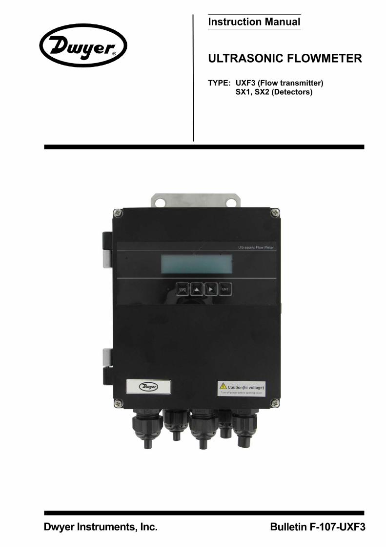
ULTRASONIC FLOWMETER
TYPE: UXF3 (Flow transmitter) SX1, SX2 (Detectors)
Instruction Manual
Dwyer Instruments, Inc. Bulletin F-107-UXF3

-i-
Introduction
This instruction manual concerns the installation, operation, and maintenance of the flow transmitter, detectors, and signal cables of the ultrasonic flow meter system. This manual should be read carefully prior to installation and operation.
Read the manual to gain an adequate understanding of proper operation of the equipment prior to installation and operation. Improper results or hazardous conditions may result of improper installation, operation or maintenance. The specifications of this flow meter are subject to change without prior notice for improvement of the product. Do not attempt to modify the flow meter. Manufacturer shall not bear any responsibility for hazardous conditions or improper operation as a result of unauthorized modification. If it becomes necessary to modify the flow meter, contact the manufacturer in advance for consulation and permission. This instruction manual should always be kept on hand by the party responsible for operation. After reading the manual, store it in an accessible location for reference. This instruction manual should be delivered to the end user upon purchase or installation. If the instruction manual has been lost, request an appropriate replacement.
Dwyer Instruments, Inc. ©Note
Reproduction of this manual in whole or part is strictly prohibited without prior written permission. Contents of the manual are subject to change without prior notice.
Issued in August, 2008
Bulletin F-107-UXF3
Modbus is a registered trademark of Schneider Automation.
-ii-
SAFETY PRECAUTIONS
Before using this product, read the following safety precautions to ensure proper use.
The following items are necessary for safe operation and must be fully observed. These safety precautions are ranked in 2 levels; "DANGER" and "CAUTION".
Warning/Symbol Meaning
Incorrect handling of the device may result in death or serious injury.
Incorrect handling may lead to a risk of physical damage or significant injury.
The items noted under " " may also result in serious equipment malfunction if not fully observed,
depending on the circumstances. All the items must be fully observed.
Caution on mounting and piping
This unit is not explosion-proof. Do not use it in a place with explosive gases. Otherwise, this may result in serious accidents such as explosion, fire, etc.
The unit should be installed in a place conforming to the installation requirements noted in this instruction manual. Otherwise, it may cause electric shocks, fire or malfunction of the unit. Install the flow meter according to the following steps to prevent it from damage, error or malfunction. During installation, ensure the inside of the unit is free from cable chips and other foreign objects. Otherwise, it may cause fire, failure or malfunction.The items under "Caution on Installation" noted in this manual must be fully observed. Careless installation may result in trouble or malfunction of the unit.
Cautions in wiring
When performing wiring termination, observe appropriate instructions to prevent ingress by moisture, dew condensation or water leaks, follow “Section 3.4 – Flow transmitter wiring” described in this manual. Before performing the wiring work, be sure to turn OFF the main power. Otherwise, electric shock may result. Do not perform wiring work outdoors in inclement weather to prevent insulation deterioration and dew condensation. Otherwise, malfunction or accelelerated deterioration may result. Be sure to connect a power source of correct rating. Use of improper power sources out of rating may cause fire. The unit must be grounded as specified. Otherwise, it may result in electric shocks, malfunction, etc. The signal cable and analog output signal cable should be wired as far away as possible from high-voltage lines to prevent entry of noise signals as it will result in malfunction of the unit. To prevent malfunction of the unit, the analog output signal cable and the power supply cable may require separate conduits.
Bulletin F-107-UXF3

-iii-
Caution on maintenance and inspection
The unit should be inspected every day to ensure proper operation. When measuring the insulation resistance between the power/output terminal and the case, follow “Section 6.2.3 – How to measure insulation resistance” described in this manual. If the fuse is blown, detect and eliminate the root cause, and then replace the fuse with a spare. If there are no spares, replace the fuse with the appropriate part specified in this manual. Use of a fuse other than specified or its short-circuit may cause an electric shock or fire. The fuse should be replaced according to “Section 6.3 – How to replace the fuse” described in this manual.
Bulletin F-107-UXF3

-iv-
CAUTION ON INSTALLATION LOCATION
(1) A location that provides enough space for periodic inspection and wiring work. (2) A location not exposed to direct sunlight nor inclement weather. (3) A location free from excessive vibration, dust, dirt and moisture. (4) A location not subjected to radiated heat from a heating furnace, etc. (5) A location not subjected to corrosive atmosphere. (6) A location not to be submerged. (7) A location remote from electrical devices (motor, transformer, etc.) which generate
electromagnetic induction noise, electrostatic noise, etc. (8) A location not subjected to excessive fluid pulsation such as pump discharge side. (9) A location that provides enough place for the length of the straight pipe. (10) A location where ambient temperature and humidity are -20 to +50°C and 95% RH or less for
flow transmitter, -20 to +60°C and 100% RH or less for detector.
Bulletin F-107-UXF3
-v-
Contents
Introduction ·········································································· i
SAFETY PRECAUTIONS··················································· ii
CAUTION ON INSTALLATION LOCATION ······················· iv
1. PRODUCT OUTLINE······················································1
1.1. Checking delivered items ·········································1
1.2. NAME AND FUNCTION OF EACH PART················2
1.2.1. Flow transmitter : UXF3 ·····································2
1.2.2. Reserved ··························································4
1.2.3. Reserved ···························································4
1.2.4. Small/middle size detector (SX1)·······················4
1.2.5. Large size detector (SX1) ··································5
1.2.6. Small diameter/High temperature detector (SX2) ·························································6
2. INSTALLATION AND BEFORE START OF OPERATION OF THE FLOW TRANSMITTER············7
2.1. Outline of installation procedure·······························7
3. INSTALLATION·······························································8
3.1. Installation location of flow transmitter······················8
3.2. Installation location of detector ·································9
3.2.1. Length of straight pipe ·····································10
3.2.2. Mounting position·············································11
3.3. Installation of flow transmitter ·································12
3.3.1. Wall mounting (Flow transmitter : UXF3 ··········12
3.3.2. 2B pipe stand mounting (Flow transmitter : UXF3 ·······················································12
3.3.3. Reserved ·························································13
3.3.4. Reserved ·························································13
3.4. Flow transmitter wiring ···········································14
3.4.1. Cautions in wiring ············································14
3.4.2. Applicable wires ···············································14
3.4.3. Treatment of wiring port ···································14
3.4.4. Wiring to each terminal ····································153.4.4.1. Flow transmitter : UXF3·····························153.4.4.2. Reserved···················································16
4. Parameter ·····································································17
4.1. Description of display/setting unit ···························17
4.1.1. Flow transmitter : UXF3 display/setting unit·····17
4.1.2. Reserved ························································17
4.1.3. Description of display/setting unit ····················18
4.2. Composition of key operation·································19
4.3. Parameter initial value list ······································24
4.4. Parameter protection··············································26
4.4.1. Parameter protection ON/OFF·························26
4.5. Display language····················································27
4.5.1. How to select the language······························27
4.6. Checking and Setting of Piping Specifications/Detector ····································28
4.6.1. Checking piping parameter ······························28
4.6.2. Piping parameter setting method ·····················29
4.7. Zero Adjustment ·····················································32
4.8. Setting of unit ·························································33
4.8.1. How to set the unit system·······························33
4.8.2. How to set the flow rate unit ····························34
4.8.3. How to set the total unit ···································35
4.9. Output Setting ························································36
4.9.1. Setting of flow rate range·································364.9.1.1. Setting of flow rate range (single range) ···364.9.1.2. Setting of analog output at error
(Burnout)············································374.9.1.3. Output limit ················································38
4.9.2. Setting the total················································394.9.2.1. Setting the total pulse (pulse value,
pulse width)········································394.9.2.2. Setting the preset value ····························414.9.2.3. TOTAL mode ·············································424.9.2.4. Determining how to dispose of total at
error (BURNOUT) ······························43
4.9.3. Setting the DO output ······································444.9.3.1. How to validate the total pulse output ·······44
4.9.4. Setting the LCD indication ·······························46
4.9.5. Setting the damping·········································47
4.9.6. Setting the low flow rate cutting ·······················48
4.10. Application operation of parameter·······················49
4.10.1. Setting automatic 2 ranges ····························49
4.10.2. Setting the Bi-directional range······················51
4.10.3. Setting the Bi-directional auto 2 range···········52
4.10.4. Rate limit························································55
4.10.5. Setting the DO output ····································574.10.5.1. How to validate outputting the FULL
SCALE 2············································574.10.5.2. How to validate the alarm output·············584.10.5.3. Setting the flow switch·····························594.10.5.4. How to validate the total switch ···············614.10.5.5. How to validate the range over output
and pulse range over output ··············624.10.5.6. How to validate the output at the minus
direction action···································63
4.10.6. Setting the DI input ········································644.10.6.1. Invalidating the DI input···························644.10.6.2. How to validate the total preset with the
external contact. ································654.10.6.3. How to validate the zero adjustment
with the external contact. ···················66
4.10.7. How to compensate the measurement value························································67
4.10.8. Setting of the operation mode························68
4.11. MAINTENANCE MODE········································69
4.11.1. How to calibrate the analog output·················69
4.11.2. How to set the constant current output···········70
4.11.3. How to check the action of total pulses··········71
4.11.4. How to check the status output ······················72
4.11.5. How to check the DI input ······························73
4.11.6. How to validate the test mode (simulated flow rate output)·······································74
4.11.7. How to validate a serial transmission (RS-485) ·························································76
Bulletin F-107-UXF3
-vi-
4.11.8. How to set the ID No. ···································· 78
4.11.9. How to confirm the software version ············· 78
4.11.10. Initializing setting parameters ······················ 79
4.11.11. How to set the detailed setting····················· 80
5. Mounting of detector ···················································· 82
5.1. Detector mounting procedure ································ 82
5.1.1. Mounting of detector ······································· 83
5.1.2. Image figure of mounting dimension ··············· 83
5.2. Selection of mounting position······························· 84
5.3. Selection of mounting method ······························· 85
5.4. Processing of mounting surface ···························· 86
5.5. How to determine the mounting position ··············· 87
5.6. Selection of acoustic couplant ······························· 88
5.7. Cable end treatment ·············································· 89
5.7.1. Cable end treatment for SX2··························· 89
5.7.2. Cable end treatment for SX1··························· 89
5.8. Reserved for Future Use ······································· 90
5.8.1. Reserved························································· 90
5.8.2. Reserved························································· 90
5.9. Mounting small-diameter and medium size sensor (SX1) ··················································· 91
5.9.1. Connection of sensor cable····························· 91
5.9.2. Assembly procedure of the sensor ·················· 93
5.9.3. Mounting method on the pipe·························· 945.9.3.1. In case of V method·································· 945.9.3.2. In case of Z method·································· 96
5.10. Mounting large size detector (SX1) ····················· 97
5.10.1. Connection of sensor cable··························· 97
5.10.2. Mounting method on the pipe························ 98
5.11. Mounting small diameter detector (SX2)·············· 99
5.12. Mounting high temperature detector (SX2)········ 100
5.12.1. Mounting of detector (in case of V method) 100
5.12.2. Mounting of detector (in case of Z method)· 101
6. CHECK AND MAINTENANCE ··································· 102
6.1. Daily Check ························································· 102
6.2. Periodic Inspection ·············································· 102
6.2.1. Checking zero point ······································ 102
6.2.2. Reapplying grease ········································ 102
6.2.3. How to measure the insulation resistance····· 1036.2.3.1. Flow transmitter : UXF3·························· 1036.2.3.2. Reserved ················································ 104
6.3. How to replace the fuse······································· 105
6.3.1. Flow transmitter : UXF3 ································ 105
6.3.2. Reserved······················································· 106
6.4. How to replace the relay······································ 107
6.4.1. Flow transmitter : UXF3 ································ 107
6.4.2. Reserved······················································· 108
6.5. How to replace the LCD ······································ 109
6.5.1. Flow transmitter : UXF3 ································ 109
6.5.2. Reserved························································110
6.6. ERROR AND REMEDY········································110
6.6.1. Display error···················································111
6.6.1.1. Checking the LCD/LED ···························1116.6.1.2. Checking the LED lit in red ······················1126.6.1.3. Checking the RAS information ················113
6.6.2. Displaying the data in maintenance mode ·····114
6.6.3. Keying is abnormal ········································115
6.6.4. Error in measured value·································116
6.6.5. Error in analog output ····································118
6.6.6. Checking received waveforms ·······················1196.6.6.1. How to connect the oscilloscope ·············1196.6.6.2. Checking sending/receiving···················· 120 6.6.7. Remedying a hardware fault ····················· 122
7. Appendix ···································································· 123
7.1. How to make gauge paper ·································· 123
7.2. Piping data ·························································· 124
Bulletin F-107-UXF3
-1-
1. PRODUCT OUTLINE
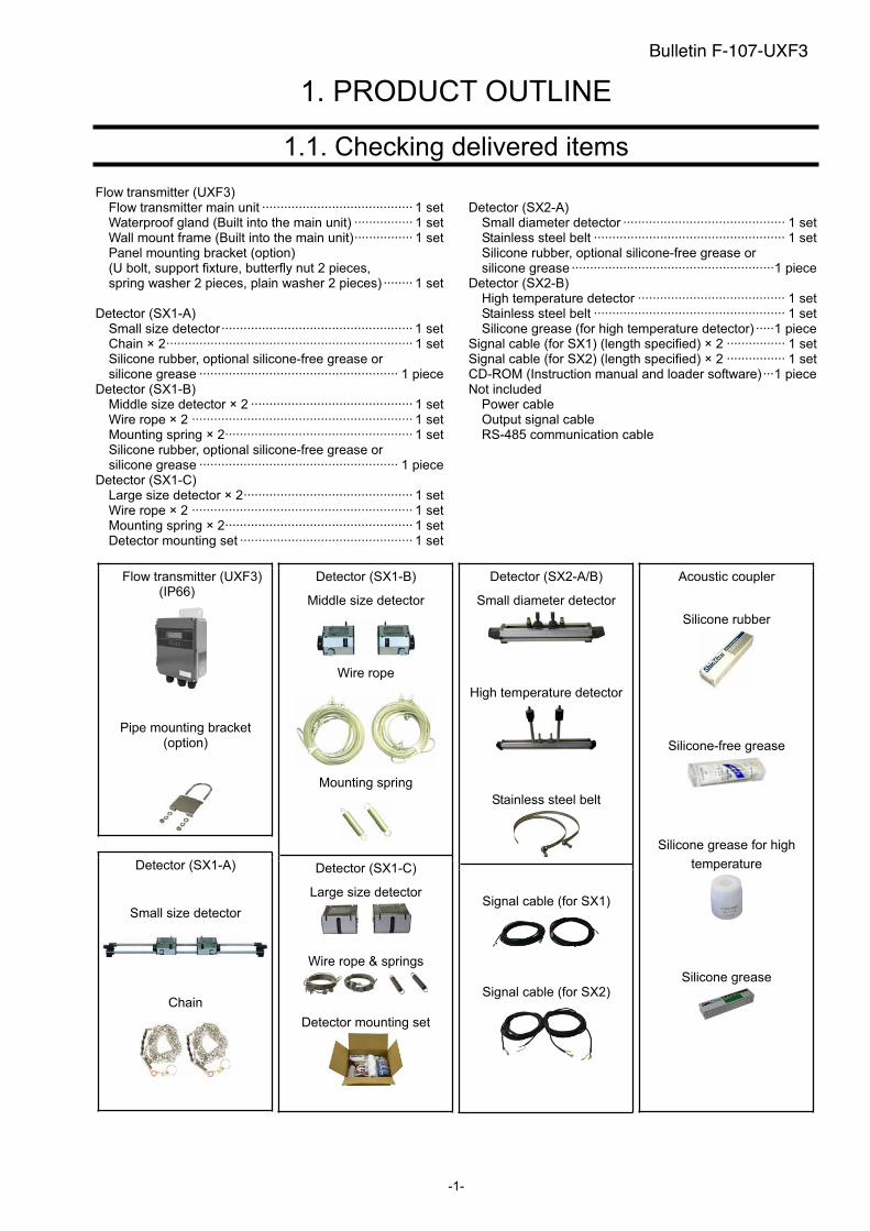
1.1. Checking delivered items
Flow transmitter (UXF3) Flow transmitter main unit ········································· 1 set Waterproof gland (Built into the main unit) ················ 1 set Wall mount frame (Built into the main unit)················ 1 set Panel mounting bracket (option) (U bolt, support fixture, butterfly nut 2 pieces, spring washer 2 pieces, plain washer 2 pieces) ········ 1 set
Detector (SX1-A) Small size detector···················································· 1 set Chain × 2··································································· 1 set Silicone rubber, optional silicone-free grease or silicone grease ······················································ 1 piece
Detector (SX1-B) Middle size detector × 2 ············································ 1 set Wire rope × 2 ···························································· 1 set Mounting spring × 2··················································· 1 set Silicone rubber, optional silicone-free grease or silicone grease ······················································ 1 piece
Detector (SX1-C) Large size detector × 2·············································· 1 set Wire rope × 2 ···························································· 1 set Mounting spring × 2··················································· 1 set Detector mounting set ··············································· 1 set
Detector (SX2-A) Small diameter detector ············································ 1 set Stainless steel belt ···················································· 1 set Silicone rubber, optional silicone-free grease or silicone grease ·······················································1 piece
Detector (SX2-B) High temperature detector ········································ 1 set Stainless steel belt ···················································· 1 set Silicone grease (for high temperature detector) ·····1 piece
Signal cable (for SX1) (length specified) × 2 ················ 1 set Signal cable (for SX2) (length specified) × 2 ················ 1 set CD-ROM (Instruction manual and loader software) ···1 piece Not included
Power cable Output signal cable RS-485 communication cable
Flow transmitter (UXF3) (IP66)
Pipe mounting bracket (option)
Detector (SX1-A)
Small size detector
Chain
Detector (SX1-B)
Middle size detector
Wire rope
Mounting spring
Detector (SX1-C)
Large size detector
Wire rope & springs
Detector mounting set
Detector (SX2-A/B)
Small diameter detector
High temperature detector
Stainless steel belt
Signal cable (for SX1)
Signal cable (for SX2)
Acoustic coupler
Silicone rubber
Silicone-free grease
Silicone grease for high
temperature
Silicone grease
Bulletin F-107-UXF3
-2-
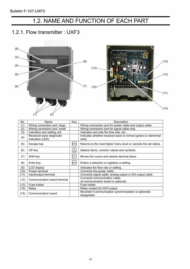
1.2. NAME AND FUNCTION OF EACH PART
1.2.1. Flow transmitter : UXF3
No. Name Key Description
(1) Wiring connection port, large Wiring connection port for power cable and output cable.
(2) Wiring connection port, small Wiring connection port for signal cable only.
(3) Indication and setting unit Indicates and sets the flow rate, etc.
(4)Received wave diagnostic indication (LED)
Indicates whether received wave is normal (green) or abnormal (red).
(5) Escape key ESC Returns to the next-higher menu level or cancels the set status.
(6) UP key Selects items, numeric values and symbols.
(7) Shift key Moves the cursor and selects decimal place.
(8) Entry key ENT Enters a selection or registers a setting.
(9) LCD display Indicates the flow rate or setting.
(10) Power terminal Connects the power cable.
(11) Input/output terminal Connects signal cable, analog output or DO output cable.
(12) Communication board terminal Connects communication cable. (A communication board is optional)
(13) Fuse holder Fuse holder
(14) Relay Relay contact for DO3 output
(15) Communication board Mounted if communication synchronization is optionally designated.
(9)
(3)
(4)
(5)
(6)
(1) (2)
(7)
(8)
(14)
(11)
(12)
(15)
(10)
(13)
Bulletin F-107-UXF3

- 3 -
Bulletin F-107-UXF3
(Page intentionally blank)
- 4 -
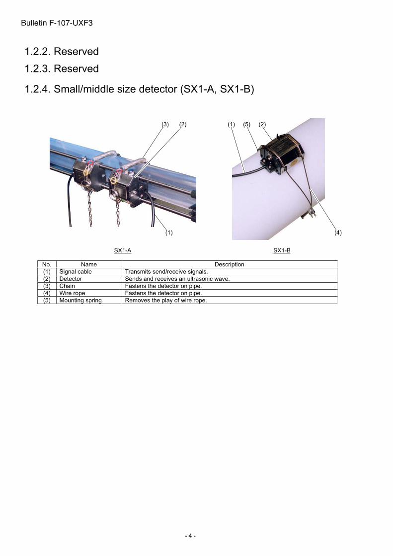
1.2.4. Small/middle size detector (SX1-A, SX1-B)
SX1-A SX1-B
No. Name Description
(1) Signal cable Transmits send/receive signals.
(2) Detector Sends and receives an ultrasonic wave.
(3) Chain Fastens the detector on pipe.
(4) Wire rope Fastens the detector on pipe.
(5) Mounting spring Removes the play of wire rope.
(3) (2)
(1)
(5)(1)
(4)
(2)
Bulletin F-107-UXF3
1.2.3. Reserved
1.2.2. Reserved

- 5 -
1.2.3. Large size detector (SX1-C)
SX1-C
No. Name Description
(1) Signal cable Transmits send/receive signals.
(2) Detector Sends and receives an ultrasonic wave.
(3) Wire rope Fastens the detector on pipe.
(4) Mounting spring Removes the play of wire rope.
(1)
(2)
(3)
(4)
Bulletin F-107-UXF3
- 6 -
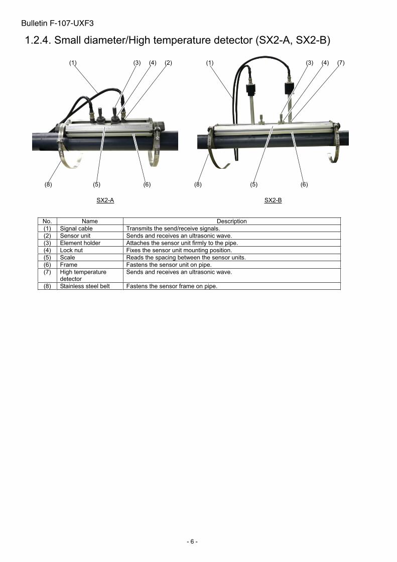
1.2.4. Small diameter/High temperature detector (SX2-A, SX2-B)
SX2-A SX2-B
No. Name Description
(1) Signal cable Transmits the send/receive signals.
(2) Sensor unit Sends and receives an ultrasonic wave.
(3) Element holder Attaches the sensor unit firmly to the pipe.
(4) Lock nut Fixes the sensor unit mounting position.
(5) Scale Reads the spacing between the sensor units.
(6) Frame Fastens the sensor unit on pipe.
(7) High temperature detector
Sends and receives an ultrasonic wave.
(8) Stainless steel belt Fastens the sensor frame on pipe.
(1) (1)(4)(3) (3)(2) (4)
(5)(8) (6)
(7)
(5)(8) (6)
Bulletin F-107-UXF3
-7-
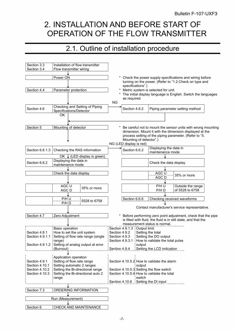
2. INSTALLATION AND BEFORE START OF OPERATION OF THE FLOW TRANSMITTER
2.1. Outline of installation procedure
Section 3.3 Section 3.4
Installation of flow transmitter Flow transmitter wiring
Power ON *
Check the power supply specifications and wiring before turning on the power. (Refer to “1.2.Check on type and specifications”.)
Section 4.4 Parameter protection * Metric system is selected for unit.
*
The initial display language is English. Switch the languages as required.
NG
Section 4.6 Checking and Setting of Piping Specifications/Detector
Section 4.6.2 Piping parameter setting method
OK
Section 5 Mounting of detector *
Be careful not to mount the sensor units with wrong mounting dimension. Mount it with the dimension displayed at the process setting of the piping parameter. (Refer to “5. Mounting of detector”.)
NG (LED display is red)
Section 6.6.1.3 Checking the RAS information Section 6.6.2 Displaying the data in maintenance mode
OK (LED display is green)
Section 6.6.2 Displaying the data in maintenance mode
Check the data display
Check the data display AGC U
AGC D 35% or more
AGC U P/H U
AGC D 35% or more
P/H D
Outside the range of 5528 to 6758
P/H U Section 6.6.6 Checking received waveforms
P/H D 5528 to 6758
Contact manufacturer's service representative.
Section 4.7 Zero Adjustment *
Before performing zero point adjustment, check that the pipe is filled with fluid, the fluid is in still state, and that the measurement status is normal.
Basic operation Section 4.9.1.3 Output limit Section 4.8.1 How to set the unit system Section 4.9.2 Setting the total
Section 4.9.3 Setting the DO output Section 4.9.1.1 Setting of flow rate range (single range) Section 4.9.3.1 How to validate the total pulse
outputSection 4.9.1.2 Setting of analog output at error (Burnout) Section 4.9.4 Setting the LCD indication
Application operation Section 4.9.1 Setting of flow rate range Section 4.10.1 Setting automatic 2 ranges
Section 4.10.5.2 How to validate the alarm output
Section 4.10.2 Setting the Bi-directional range Section 4.10.5.3 Setting the flow switch Section 4.10.3 Setting the Bi-directional auto 2
range Section 4.10.5.4 How to validate the total
switch Section 4.10.6 Setting the DI input
Section 7.3 ORDERING INFORMATION
Run (Measurement)
Section 6 CHECK AND MAINTENANCE
Bulletin F-107-UXF3
-8-
3. INSTALLATION
Select an installation location that satisfies the following conditions for ease of maintenance and inspection, service life ofthe instrument, and assurance of reliability all considered.
(1) A location where ambient temperature and humidity are -20 to +55°C and 90% RH or less for transmitter (UXF3), -20 to +80°C and 90% RH or less for detector (SX1) and -20 to +60°C and 90% RH or less for detector (SX2).
(2) A location not exposed to direct sunlight nor inclement weather. (3) Space for periodic inspection and wiring work is available. (4) A location not subjected to radiated heat from a heating furnace, etc. (5) A location not subjected to corrosive atmosphere. (6) A location not to be submerged. (7) A location free from excessive vibration, dust, dirt and moisture.
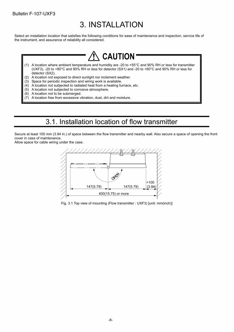
3.1. Installation location of flow transmitter
Secure at least 100 mm (3.94 in.) of space between the flow transmitter and nearby wall. Also secure a space of opening the front cover in case of maintenance. Allow space for cable wiring under the case.
OPEN
147(5.79)
>100
(3.94)147(5.79)
400(15.75) or more
Fig. 3.1 Top view of mounting (Flow transmitter : UXF3) [unit: mm(inch)]
�������
Bulletin F-107-UXF3
-9-
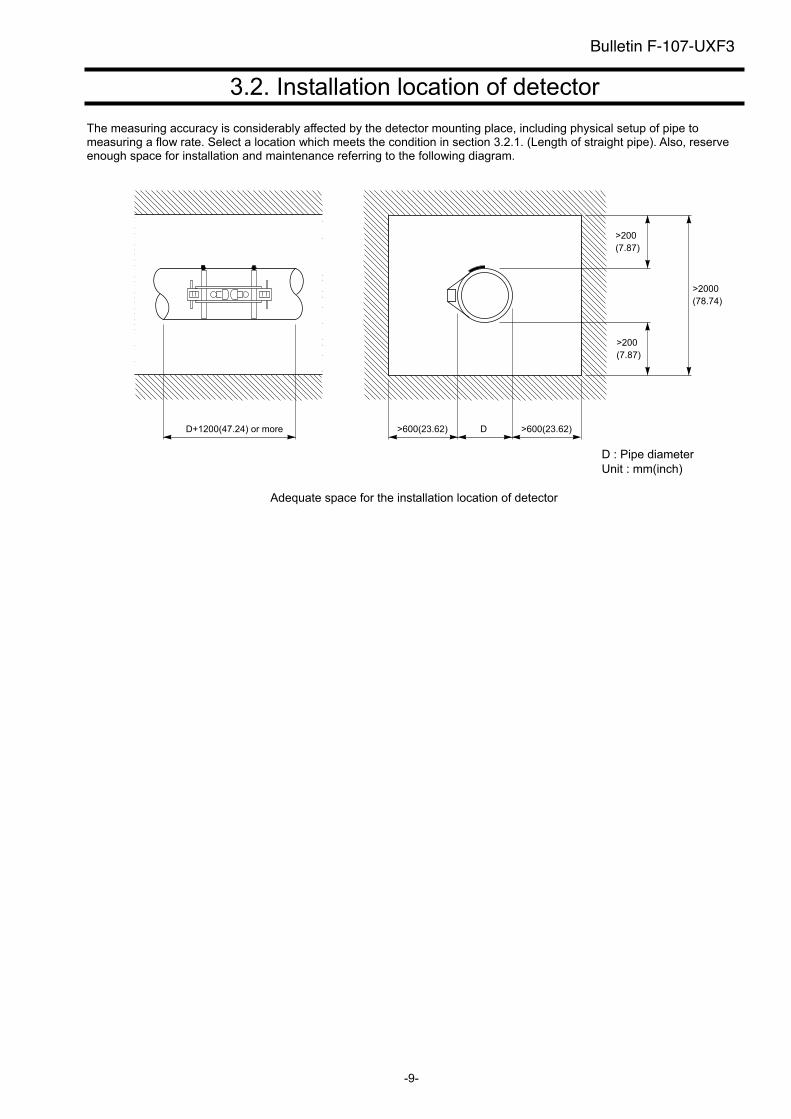
3.2. Installation location of detector
The measuring accuracy is considerably affected by the detector mounting place, including physical setup of pipe to measuring a flow rate. Select a location which meets the condition in section 3.2.1. (Length of straight pipe). Also, reserve enough space for installation and maintenance referring to the following diagram.
D+1200(47.24) or more >600(23.62) D >600(23.62)
D : Pipe diameter
Unit : mm(inch)
Adequate space for the installation location of detector
Bulletin F-107-UXF3
>200
(7.87)
>200
(7.87)
>2000
(78.74)
-10-
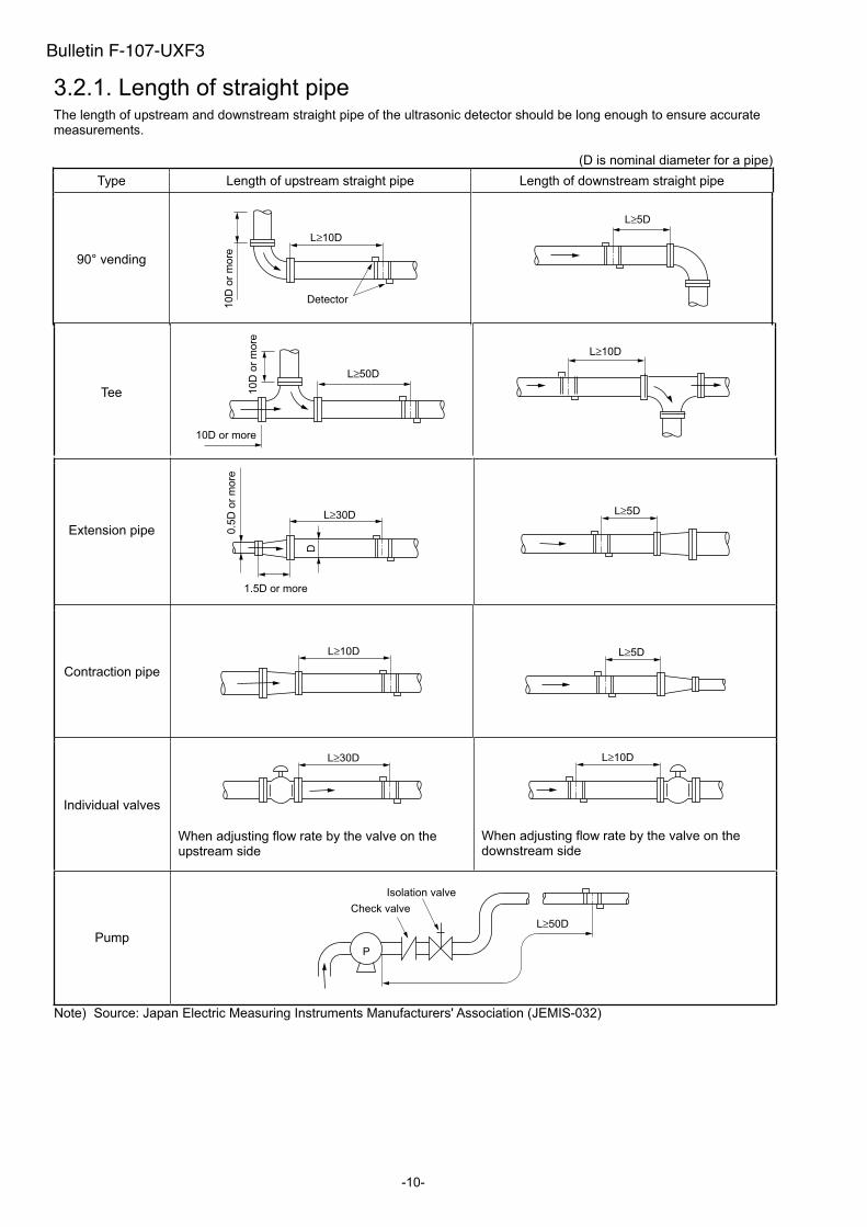
3.2.1. Length of straight pipe The length of upstream and downstream straight pipe of the ultrasonic detector should be long enough to ensure accurate measurements.
(D is nominal diameter for a pipe)
Type Length of upstream straight pipe Length of downstream straight pipe
90° vending
L≥10D10D
or
more
L≥5D
Tee
L≥50D
10D or more
10D
or
more
L≥10D
Extension pipe
L≥30D
1.5D or more
D
0.5
D o
r m
ore
L≥5D
Contraction pipe
L≥10D L≥5D
Individual valves
L≥30D
When adjusting flow rate by the valve on the upstream side
L≥10D
When adjusting flow rate by the valve on the downstream side
PumpL≥50D
Check valve
P
Isolation valve
Note) Source: Japan Electric Measuring Instruments Manufacturers' Association (JEMIS-032)
Bulletin F-107-UXF3
-11-
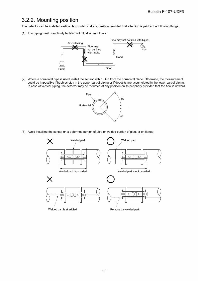
3.2.2. Mounting position The detector can be installed vertical, horizontal or at any position provided that attention is paid to the following things.
(1) The piping must completely be filled with fluid when it flows.
Pump
Air-collecting
Good
Good
Pipe may
not be filled
with liquid.
Pipe may not be filled with liquid.
(2) Where a horizontal pipe is used, install the sensor within ±45° from the horizontal plane. Otherwise, the measurement could be impossible if bubbles stay in the upper part of piping or if deposits are accumulated in the lower part of piping. In case of vertical piping, the detector may be mounted at any position on its periphery provided that the flow is upward.
Horizontal
Pipe
45
45
(3) Avoid installing the sensor on a deformed portion of pipe or welded portion of pipe, or on flange.
Welded part
Welded part is provided.
Welded part
Welded part is not provided.
Welded part is straddled. Remove the welded part.
Bulletin F-107-UXF3
- 12-
3.3. Installation of flow transmitter
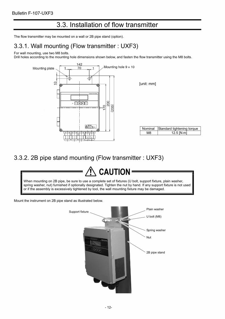
The flow transmitter may be mounted on a wall or 2B pipe stand (option).
3.3.1. Wall mounting (Flow transmitter : UXF3) For wall mounting, use two M8 bolts. Drill holes according to the mounting hole dimensions shown below, and fasten the flow transmitter using the M8 bolts.
3.3.2. 2B pipe stand mounting (Flow transmitter : UXF3)
When mounting on 2B pipe, be sure to use a complete set of fixtures (U bolt, support fixture, plain washer, spring washer, nut) furnished if optionally designated. Tighten the nut by hand. If any support fixture is not used or if the assembly is excessively tightened by tool, the wall mounting fixture may be damaged.
Mount the instrument on 2B pipe stand as illustrated below.
Nominal Standard tightening torque
M8 12.5 [N m]
2B pipe stand
U bolt (M8)
Plain washer
Spring washer
Nut
Support fixture
Bulletin F-107-UXF3
[unit: mm]

Bulletin F-107-UXF3
(Page intentionally blank)
- 14 -
3.4. Flow transmitter wiring
3.4.1. Cautions in wiring
(1) Use a special coaxial cable as a signal cable between the detector and flow transmitter. Do not provide a junction or splice of the signal cable midway.
(2) The signal cable between the detector or flow transmitter should be run in metallic conduits. Upstream and downstream signal cables may be put in the same conduit but, to avoid interference, do not put the power cable together with the signal cables.
(3) For output signal, use a shielded cable, where possible. (4) To avoid noise interference, do not put the cables together with heavy duty line or the like into the same
duct.(5) If a ground wire is included in the power cable, connect it to ground properly. (6) A power switch is not provided on the instrument and must be mounted separately if desired. (7) Seal unused wiring ports with available caps.
3.4.2. Applicable wires Use the following cables.
Power cable : 3-wire or 2-wire cabtyre cable Nominal sectional area 0.75mm
2(0.00117 in2) or more
Outside diameter 11mm (0.433 in) Output signal cable : 2-wire or multi-wire cabtyre cable as required
Outside diameter 11mm (0.433 in) Detector-flow transmitter cable : Signal cable by type designation
In case of SX1 : High-frequency coaxial double shield cable with characteristic impedance of 50
Outside diameter 7.3mm (0.288 in)
In case of SX2 : High-frequency coaxial double shield cable with characteristic impedance of 50
With one-side waterproof BNC connector Outside diameter 7.3mm (0.288 in.)
3.4.3. Treatment of wiring port The casing of the flow transmitter is IP66. However, if installed in a humid place, the wiring ports must be made airtight to avoid ingress of moisture, condensation, etc. Be sure to use the waterproof glands furnished with the instrument in order to ensure the waterproof capability. A gland, which is not ready to be used, should be sealed with the supplied cover.
Do not install the instrument where there is a risk of flooding.
Bulletin F-107-UXF3
-15-
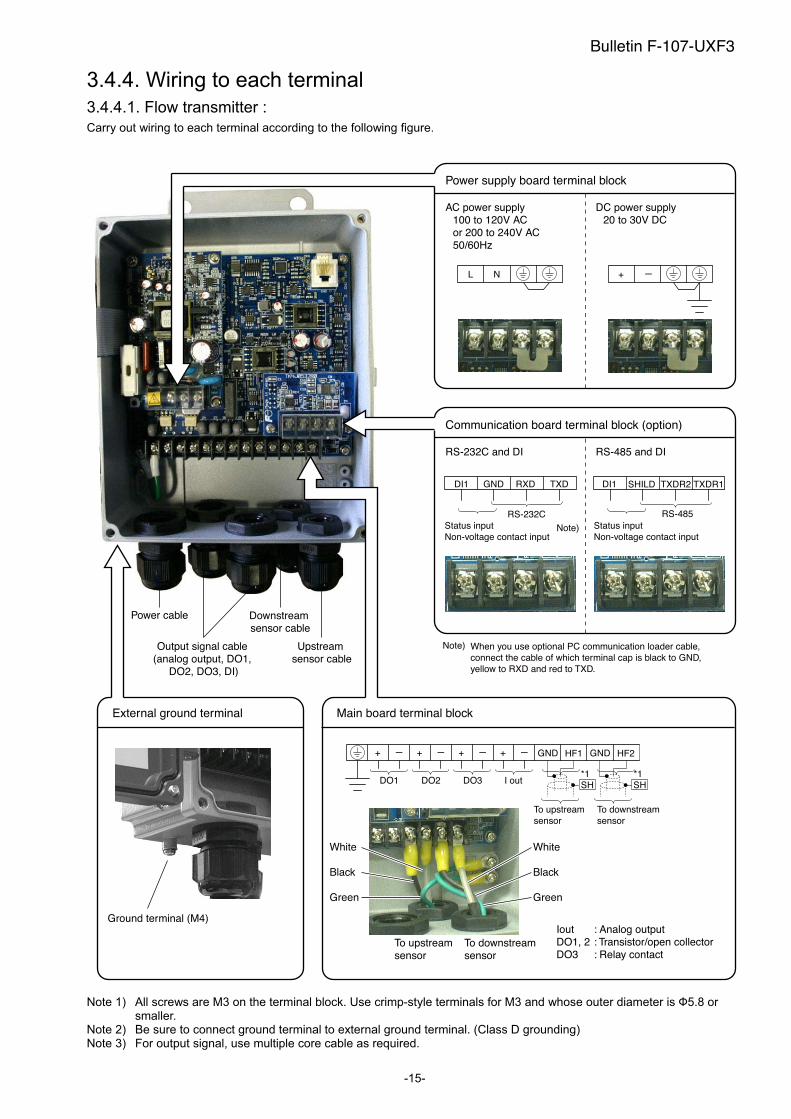
3.4.4. Wiring to each terminal
3.4.4.1. Flow transmitter :
Carry out wiring to each terminal according to the following figure.
External ground terminal
Power supply board terminal block
AC power supply 100 to 120V AC or 200 to 240V AC50/60Hz
Power cable Downstream sensor cable
Upstreamsensor cable
Output signal cable (analog output, DO1,
DO2, DO3, DI)
Ground terminal (M4)
Main board terminal block
Iout : Analog outputDO1, 2 : Transistor/open collectorDO3 : Relay contact
+ - -+
DO1 DO2 DO3
+ - + -
I out
To upstream sensor
White
Black
Green
White
Black
Green
To downstream sensor
GND HF1 HF2GND
NL
DC power supply20 to 30V DC
-+
Communication board terminal block (option)
RS-232C and DI RS-485 and DI
TXDR1SHILD
RS-485
TXDR2DI1
Status inputNon-voltage contact input
TXDDI1 GND RXD
RS-232C
Note)
Note) When you use optional PC communication loader cable, connect the cable of which terminal cap is black to GND, yellow to RXD and red to TXD.
Status inputNon-voltage contact input
*1*1SHSH
To downstream sensor
To upstream sensor
Note 1) All screws are M3 on the terminal block. Use crimp-style terminals for M3 and whose outer diameter is 5.8 or smaller.
Note 2) Be sure to connect ground terminal to external ground terminal. (Class D grounding) Note 3) For output signal, use multiple core cable as required.
Bulletin F-107-UXF3

-16-
3.4.4.2. Reserved
Bulletin F-107-UXF3
(Page intentionally blank)
- 17 -
4. Parameter
4.1. Description of display/setting unit
Display unit and setting unit are as shown below.
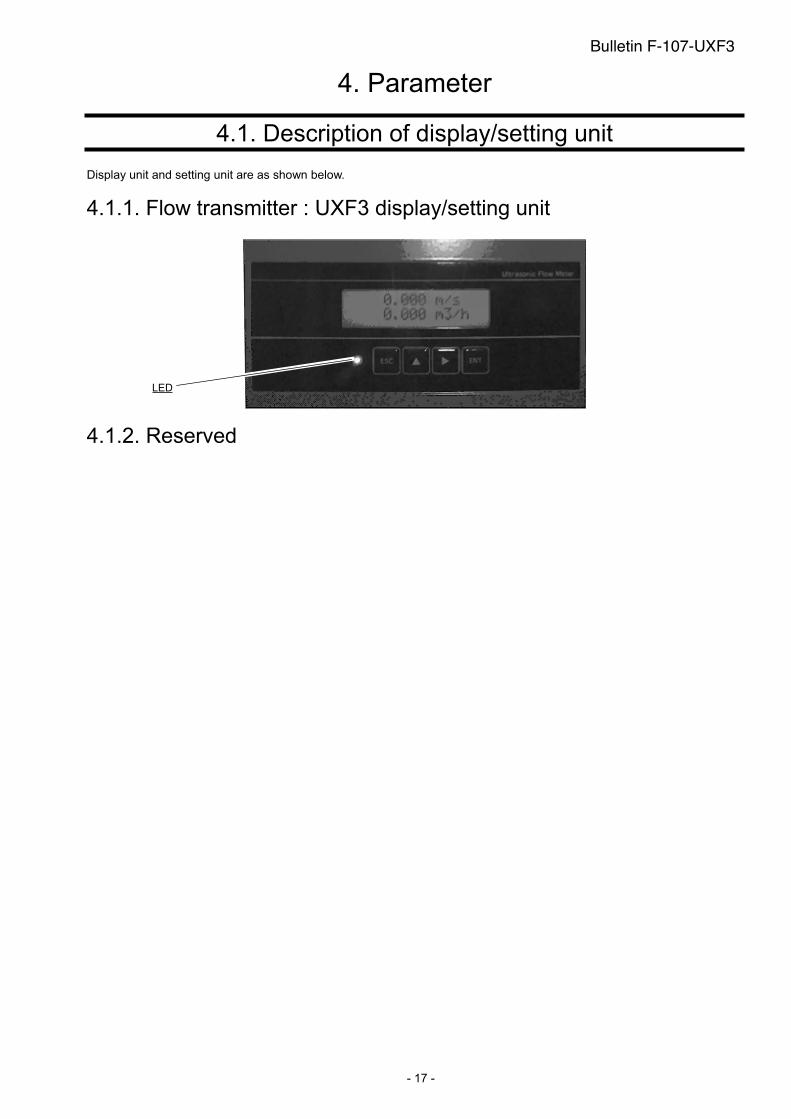
4.1.1. Flow transmitter : UXF3 display/setting unit
4.1.2. Reserved
LED
Bulletin F-107-UXF3
-18-
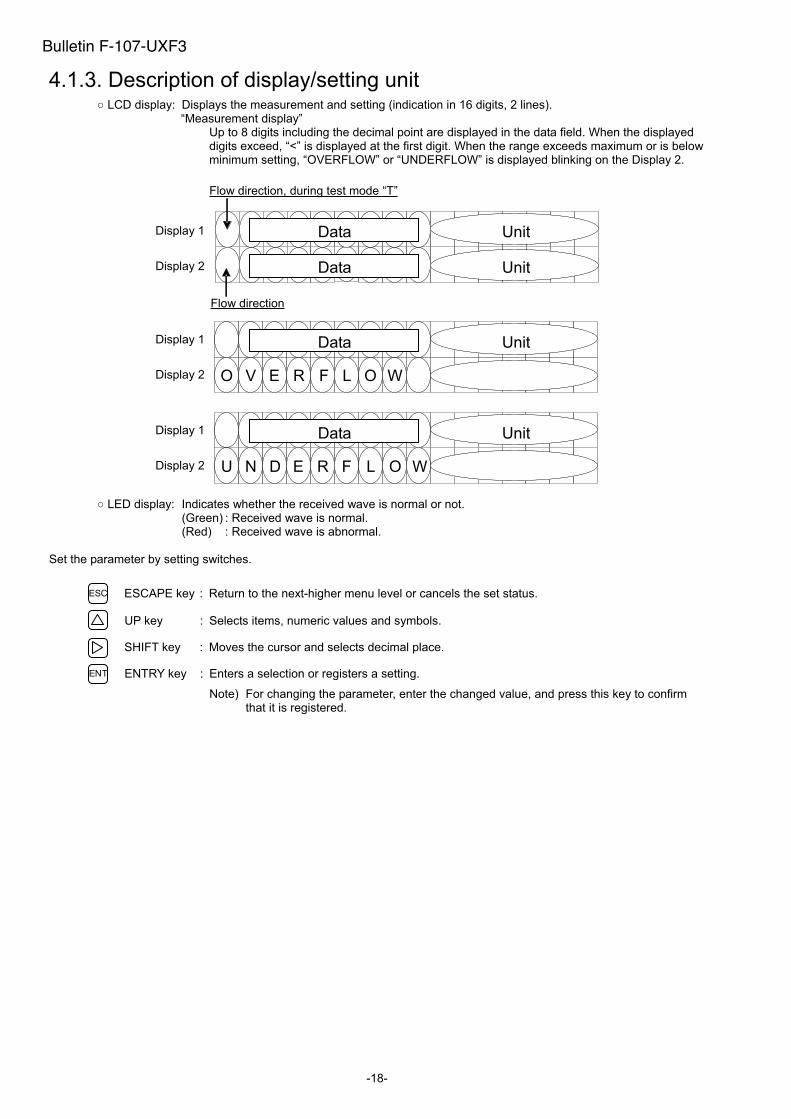
4.1.3. Description of display/setting unit LCD display: Displays the measurement and setting (indication in 16 digits, 2 lines).
“Measurement display” Up to 8 digits including the decimal point are displayed in the data field. When the displayed digits exceed, “<” is displayed at the first digit. When the range exceeds maximum or is below minimum setting, “OVERFLOW” or “UNDERFLOW” is displayed blinking on the Display 2.
LED display: Indicates whether the received wave is normal or not. (Green) : Received wave is normal. (Red) : Received wave is abnormal.
Set the parameter by setting switches.
ESC ESCAPE key : Return to the next-higher menu level or cancels the set status.
UP key : Selects items, numeric values and symbols.
SHIFT key : Moves the cursor and selects decimal place.
ENT ENTRY key : Enters a selection or registers a setting.
Note) For changing the parameter, enter the changed value, and press this key to confirm that it is registered.
Flow direction
Display 1
Flow direction, during test mode “T”
Data
Display 2 Data
Unit
Unit
V E R L O WF
Data UnitDisplay 1
Display 2 O
N E R L O WF
Data UnitDisplay 1
Display 2 U D
Bulletin F-107-UXF3
-19-
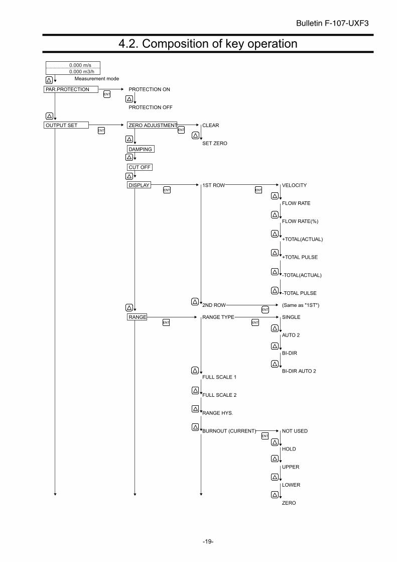
4.2. Composition of key operation
0.000 m/s
0.000 m3/h
Measurement mode
PAR.PROTECTION PROTECTION ON
PROTECTION OFF
OUTPUT SET ZERO ADJUSTMENT CLEAR
SET ZERO
DAMPING
CUT OFF
DISPLAY 1ST ROW VELOCITY
FLOW RATE
FLOW RATE(%)
+TOTAL(ACTUAL)
+TOTAL PULSE
-TOTAL(ACTUAL)
-TOTAL PULSE
2ND ROW (Same as "1ST")
RANGE RANGE TYPE SINGLE
AUTO 2
BI-DIR
BI-DIR AUTO 2
FULL SCALE 1
FULL SCALE 2
RANGE HYS.
BURNOUT (CURRENT) NOT USED
HOLD
UPPER
LOWER
ZERO
ENT
ENT ENT
ENT
ENT ENT
ENT
ENT
ENT
Bulletin F-107-UXF3
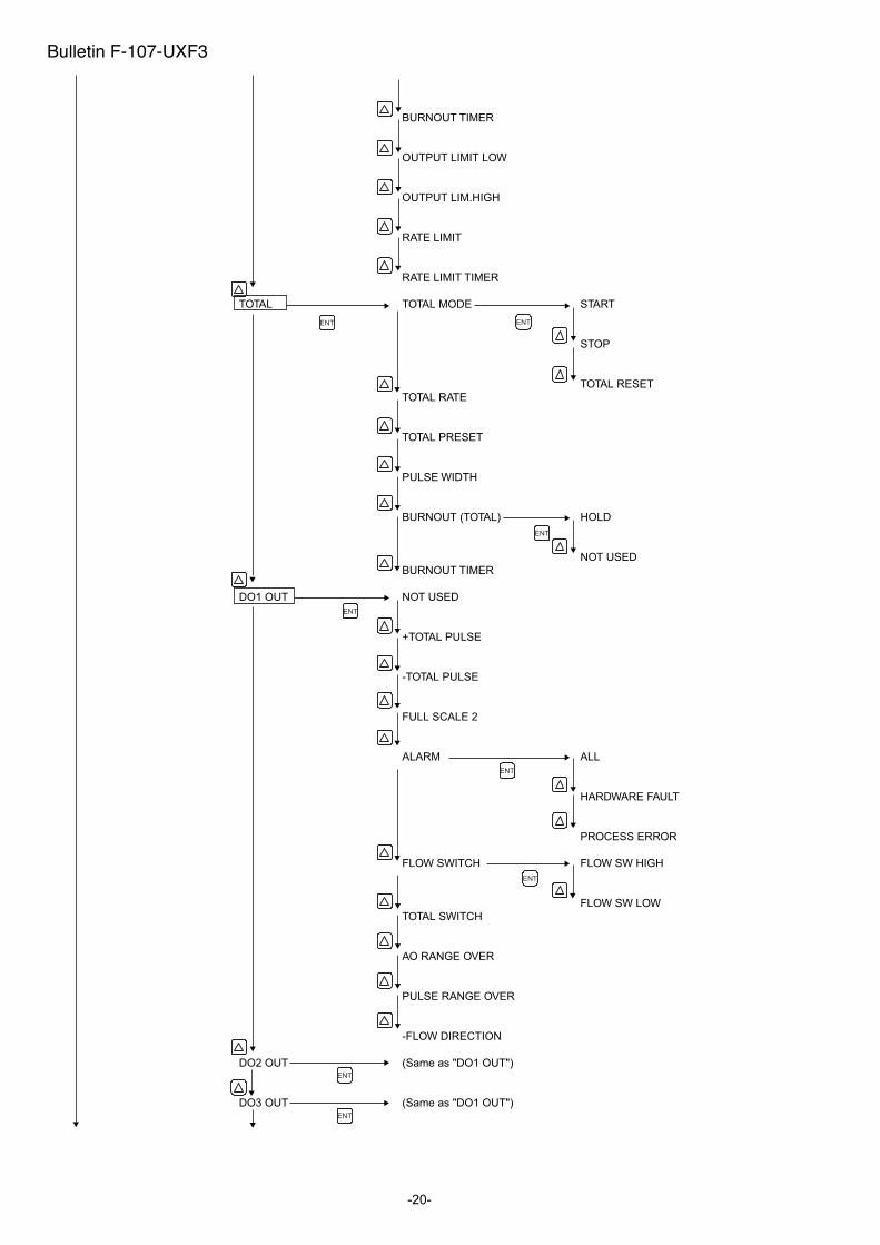
-20-
BURNOUT TIMER
OUTPUT LIMIT LOW
OUTPUT LIM.HIGH
RATE LIMIT
RATE LIMIT TIMER
TOTAL TOTAL MODE START
STOP
TOTAL RESET
TOTAL RATE
TOTAL PRESET
PULSE WIDTH
BURNOUT (TOTAL) HOLD
NOT USED
BURNOUT TIMER
DO1 OUT NOT USED
+TOTAL PULSE
-TOTAL PULSE
FULL SCALE 2
ALARM ALL
HARDWARE FAULT
PROCESS ERROR
FLOW SWITCH FLOW SW HIGH
FLOW SW LOW
TOTAL SWITCH
AO RANGE OVER
PULSE RANGE OVER
-FLOW DIRECTION
DO2 OUT (Same as "DO1 OUT")
DO3 OUT (Same as "DO1 OUT")
ENT
ENT
ENT
ENT
ENT
ENT
ENT
ENT
Bulletin F-107-UXF3
-21-
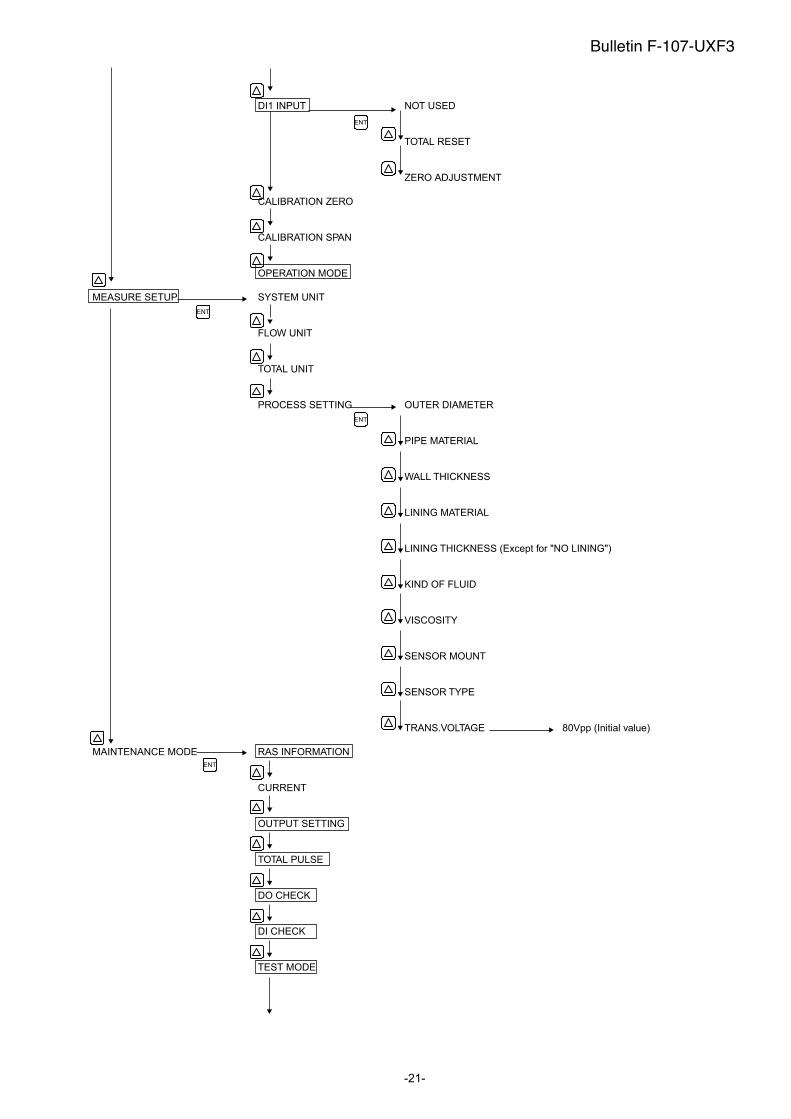
DI1 INPUT NOT USED
TOTAL RESET
ZERO ADJUSTMENT
CALIBRATION ZERO
CALIBRATION SPAN
OPERATION MODE
MEASURE SETUP SYSTEM UNIT
FLOW UNIT
TOTAL UNIT
PROCESS SETTING OUTER DIAMETER
PIPE MATERIAL
WALL THICKNESS
LINING MATERIAL
LINING THICKNESS (Except for "NO LINING")
KIND OF FLUID
VISCOSITY
SENSOR MOUNT
SENSOR TYPE
TRANS.VOLTAGE 80Vpp (Initial value)
MAINTENANCE MODE RAS INFORMATION
CURRENT
OUTPUT SETTING
TOTAL PULSE
DO CHECK
DI CHECK
TEST MODE
ENT
ENT
ENT
ENT
Bulletin F-107-UXF3
-22-
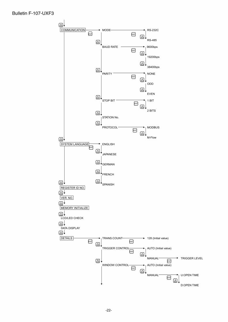
COMMUNICATION MODE RS-232C
RS-485
BAUD RATE 9600bps
19200bps
38400bps
PARITY NONE
ODD
EVEN
STOP BIT 1 BIT
2 BITS
STATION No.
PROTOCOL MODBUS
M-Flow
SYSTEM LANGUAGE ENGLISH
JAPANESE
GERMAN
FRENCH
SPANISH
REGISTER ID NO.
VER. NO.
MEMORY INITIALIZE
LCD/LED CHECK
DATA DISPLAY
DETAILS TRANS.COUNT 128 (Initial value)
TRIGGER CONTROL AUTO (Initial value)
MANUAL TRIGGER LEVEL
WINDOW CONTROL AUTO (Initial value)
MANUAL U:OPEN TIME
D:OPEN TIME
ENT
ENT
ENT
ENT
ENT
ENT
ENT
ENT
ENT
ENT
ENT
ENT
ENT
Bulletin F-107-UXF3
-23-
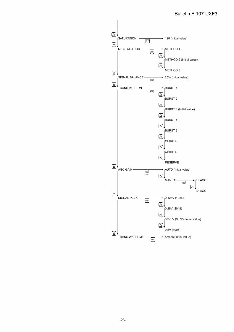
SATURATION 128 (Initial value)
MEAS.METHOD METHOD 1
METHOD 2 (Initial value)
METHOD 3
SIGNAL BALANCE 25% (Initial value)
TRANS.PATTERN BURST 1
BURST 2
BURST 3 (Initial value)
BURST 4
BURST 5
CHIRP 4
CHIRP 8
RESERVE
AGC GAIN AUTO (Initial value)
MANUAL U: AGC
D: AGC
SIGNAL PEEK 0.125V (1024)
0.25V (2048)
0.375V (3072) (Initial value)
0.5V (4096)
TRANS.WAIT TIME 5msec (Initial value)
ENT
ENT
ENT
ENT
ENT
ENT
ENT
ENT
Bulletin F-107-UXF3
- 24 -
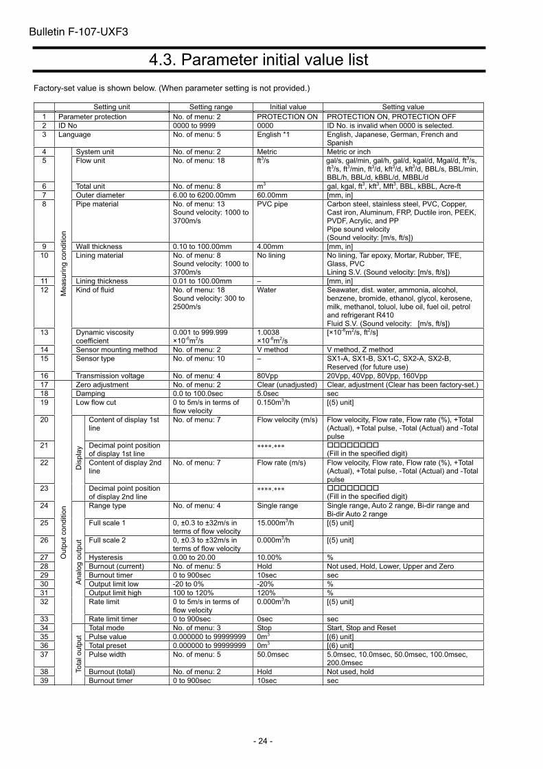
4.3. Parameter initial value list
Factory-set value is shown below. (When parameter setting is not provided.)
Setting unit Setting range Initial value Setting value
1 Parameter protection No. of menu: 2 PROTECTION ON PROTECTION ON, PROTECTION OFF
2 ID No 0000 to 9999 0000 ID No. is invalid when 0000 is selected.
3 Language No. of menu: 5 English *1 English, Japanese, German, French and Spanish
4 System unit No. of menu: 2 Metric Metric or inch
5 Flow unit No. of menu: 18 ft3/s gal/s, gal/min, gal/h, gal/d, kgal/d, Mgal/d, ft3/s,ft3/s, ft3/min, ft3/d, kft3/d, kft /d, BBL/s, BBL/min, BBL/h, BBL/d, kBBL/d, MBBL/d
6 Total unit No. of menu: 8 m3 gal, kgal, ft3, kft3, Mft3, BBL, kBBL, Acre-ft
7 Outer diameter 6.00 to 6200.00mm 60.00mm [mm, in]
8 Pipe material No. of menu: 13 Sound velocity: 1000 to 3700m/s
PVC pipe Carbon steel, stainless steel, PVC, Copper, Cast iron, Aluminum, FRP, Ductile iron, PEEK, PVDF, Acrylic, and PP Pipe sound velocity (Sound velocity: [m/s, ft/s])
9 Wall thickness 0.10 to 100.00mm 4.00mm [mm, in]
10 Lining material No. of menu: 8 Sound velocity: 1000 to 3700m/s
No lining No lining, Tar epoxy, Mortar, Rubber, TFE,Glass, PVC Lining S.V. (Sound velocity: [m/s, ft/s])
11 Lining thickness 0.01 to 100.00mm – [mm, in]
12 Kind of fluid No. of menu: 18 Sound velocity: 300 to 2500m/s
Water Seawater, dist. water, ammonia, alcohol, benzene, bromide, ethanol, glycol, kerosene, milk, methanol, toluol, lube oil, fuel oil, petrol and refrigerant R410 Fluid S.V. (Sound velocity: [m/s, ft/s])
13 Dynamic viscosity coefficient
0.001 to 999.999 ×10⁻⁶m2/s
1.0038×10⁻⁶m2/s
[×10-6m2/s, ft2/s]
14 Sensor mounting method No. of menu: 2 V method V method, Z method
15 Sensor type No. of menu: 10 – SX1-A, SX1-B, SX1-C, SX2-A, SX2-B, Reserved (for future use)
16
Me
asu
rin
g c
on
ditio
n
Transmission voltage No. of menu: 4 80Vpp 20Vpp, 40Vpp, 80Vpp, 160Vpp
17 Zero adjustment No. of menu: 2 Clear (unadjusted) Clear, adjustment (Clear has been factory-set.)
18 Damping 0.0 to 100.0sec 5.0sec sec
19 Low flow cut 0 to 5m/s in terms of flow velocity
0.150m3/h [(5) unit]
20 Content of display 1st line
No. of menu: 7 Flow velocity (m/s) Flow velocity, Flow rate, Flow rate (%), +Total (Actual), +Total pulse, -Total (Actual) and -Total pulse
21 Decimal point position of display 1st line
.(Fill in the specified digit)
22 Content of display 2nd line
No. of menu: 7 Flow rate (m/s) Flow velocity, Flow rate, Flow rate (%), +Total (Actual), +Total pulse, -Total (Actual) and -Total pulse
23
Dis
pla
y
Decimal point position of display 2nd line
.(Fill in the specified digit)
24 Range type No. of menu: 4 Single range Single range, Auto 2 range, Bi-dir range and Bi-dir Auto 2 range
25 Full scale 1 0, ±0.3 to ±32m/s in terms of flow velocity
15.000m3/h [(5) unit]
26 Full scale 2 0, ±0.3 to ±32m/s in terms of flow velocity
0.000m3/h [(5) unit]
27 Hysteresis 0.00 to 20.00 10.00% %
28 Burnout (current) No. of menu: 5 Hold Not used, Hold, Lower, Upper and Zero
29 Burnout timer 0 to 900sec 10sec sec
30 Output limit low -20 to 0% -20% %
31 Output limit high 100 to 120% 120% %
32 Rate limit 0 to 5m/s in terms of flow velocity
0.000m3/h [(5) unit]
33
An
alo
g o
utp
ut
Rate limit timer 0 to 900sec 0sec sec
34 Total mode No. of menu: 3 Stop Start, Stop and Reset
35 Pulse value 0.000000 to 99999999 0m3 [(6) unit]
36 Total preset 0.000000 to 99999999 0m3 [(6) unit]
37 Pulse width No. of menu: 5 50.0msec 5.0msec, 10.0msec, 50.0msec, 100.0msec, 200.0msec
38 Burnout (total) No. of menu: 2 Hold Not used, hold
39
Ou
tpu
t co
nd
itio
n
Tota
l o
utp
ut
Burnout timer 0 to 900sec 10sec sec
Bulletin F-107-UXF3
3
- 25 -
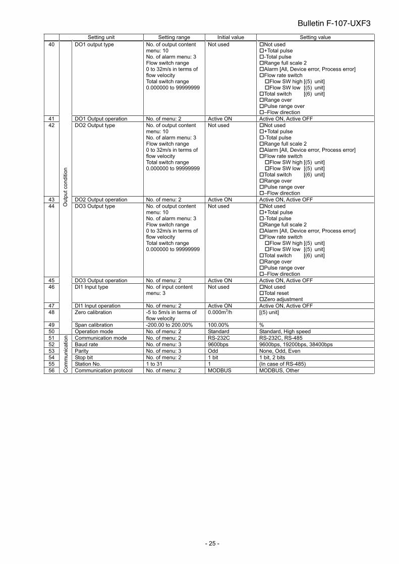
Setting unit Setting range Initial value Setting value
40 DO1 output type No. of output content menu: 10 No. of alarm menu: 3 Flow switch range 0 to 32m/s in terms of flow velocity Total switch range 0.000000 to 99999999
Not used Not used +Total pulse -Total pulse Range full scale 2 Alarm [All, Device error, Process error] Flow rate switch
Flow SW high [(5) unit]Flow SW low [(5) unit]
Total switch [(6) unit] Range over Pulse range over –Flow direction
41 DO1 Output operation No. of menu: 2 Active ON Active ON, Active OFF
42 DO2 Output type No. of output content menu: 10 No. of alarm menu: 3 Flow switch range 0 to 32m/s in terms of flow velocity Total switch range 0.000000 to 99999999
Not used Not used +Total pulse -Total pulse Range full scale 2 Alarm [All, Device error, Process error] Flow rate switch
Flow SW high [(5) unit]Flow SW low [(5) unit]
Total switch [(6) unit]Range over Pulse range over –Flow direction
43 DO2 Output operation No. of menu: 2 Active ON Active ON, Active OFF
44 DO3 Output type No. of output content menu: 10 No. of alarm menu: 3 Flow switch range 0 to 32m/s in terms of flow velocity Total switch range 0.000000 to 99999999
Not used Not used +Total pulse -Total pulse Range full scale 2 Alarm [All, Device error, Process error] Flow rate switch
Flow SW high [(5) unit]Flow SW low [(5) unit]
Total switch [(6) unit]Range over Pulse range over –Flow direction
45 DO3 Output operation No. of menu: 2 Active ON Active ON, Active OFF
46 DI1 Input type No. of input content menu: 3
Not used Not used Total reset Zero adjustment
47 DI1 Input operation No. of menu: 2 Active ON Active ON, Active OFF
48 Zero calibration -5 to 5m/s in terms of flow velocity
0.000m3/h [(5) unit]
49 Span calibration -200.00 to 200.00% 100.00% %
50
Ou
tpu
t co
nd
itio
n
Operation mode No. of menu: 2 Standard Standard, High speed
51 Communication mode No. of menu: 2 RS-232C RS-232C, RS-485
52 Baud rate No. of menu: 3 9600bps 9600bps, 19200bps, 38400bps
53 Parity No. of menu: 3 Odd None, Odd, Even
54 Stop bit No. of menu: 2 1 bit 1 bit, 2 bits
55 Station No. 1 to 31 1 (In case of RS-485)
56 Co
mm
un
ica
tio
n
Communication protocol No. of menu: 2 MODBUS MODBUS, Other
Bulletin F-107-UXF3
-26-
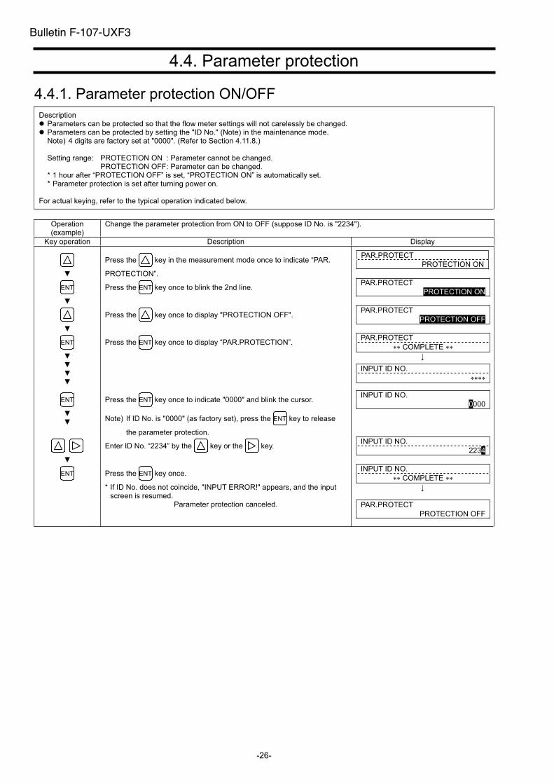
4.4. Parameter protection
4.4.1. Parameter protection ON/OFF
Description Parameters can be protected so that the flow meter settings will not carelessly be changed. Parameters can be protected by setting the "ID No." (Note) in the maintenance mode. Note) 4 digits are factory set at "0000". (Refer to Section 4.11.8.)
Setting range: PROTECTION ON : Parameter cannot be changed. PROTECTION OFF : Parameter can be changed.
* 1 hour after “PROTECTION OFF” is set, “PROTECTION ON” is automatically set. * Parameter protection is set after turning power on.
For actual keying, refer to the typical operation indicated below.
Operation (example)
Change the parameter protection from ON to OFF (suppose ID No. is "2234").
Key operation Description Display
Press the key in the measurement mode once to indicate “PAR.
PROTECTION”.
PAR.PROTECT
PROTECTION ON
ENT Press the ENT key once to blink the 2nd line. PAR.PROTECT
PROTECTION ON
Press the key once to display "PROTECTION OFF". PAR.PROTECT
PROTECTION OFF
PAR.PROTECT
COMPLETE ENT Press the ENT key once to display “PAR.PROTECTION”.
INPUT ID NO.
ENT Press the ENT key once to indicate "0000" and blink the cursor.
Note) If ID No. is "0000" (as factory set), press the ENT key to release
the parameter protection.
INPUT ID NO.
0000
Enter ID No. “2234” by the key or the key. INPUT ID NO.
2234
ENT Press the ENT key once.
* If ID No. does not coincide, "INPUT ERROR!" appears, and the input screen is resumed.
INPUT ID NO.
COMPLETE
Parameter protection canceled. PAR.PROTECT
PROTECTION OFF
Bulletin F-107-UXF3

-27-
4.5. Display language
4.5.1. How to select the language
Description Indication language (English, Japanese, German, French, Spanish) is selectable.
Setting contents English (default setting), Japanese, German, French, Spanish
For actual keying, refer to the typical operation indicated below. Set the parameter protection to OFF beforehand. (See Section 4.4.1.)
Operation (example)
Select English for the display language.
Key operation Description Display
Press the key 4 times to display “MAINTENANCE MODE”. MAINTENANCE MODE
ENT Press the ENT key once to display “RAS INFORMATION”. RAS INFORMATION
0000000000000000
Press the key 8 times to display “SYSTEM LANGUAGE”. SYSTEM LANGUAGE
JAPANESE
ENT Press the ENT key once to blink on the 2nd line. SYSTEM LANGUAGE
JAPANESE
Press the key 4 times to display “ENGLISH”. SYSTEM LANGUAGE
ENGLISH
Press the ENT key once to register. SYSTEM LANGUAGE
COMPLETE ENT
English has been registered. SYSTEM LANGUAGE
ENGLISH
ESC Press the ESC key or the key to display the measurement mode. 0.000 m/s
0.000 m3/h
Operation (example)
Select Japanese for the display language.
Key operation Description Display
Press the key 4 times to display “MAINTENANCE MODE”. MAINTENANCE MODE
ENT Press the ENT key once to display “RAS INFORMATION”. RAS INFORMAITION
0000000000000000
Press the key 8 times to display “SYSTEM LANGUAGE”. SYSTEM LANGUAGE
ENGLISH
ENT Press the ENT key once to blink on the 2nd line. SYSTEM LANGUAGE
ENGLISH
Press the key 4 times to display “JAPANESE”. SYSTEM LANGUAGE
JAPANESE
Press the ENT key once to register. SYSTEM LANGUAGE
ENT
Japanese has been registered. (LANGUAGE)
(JAPANESE)
ESC Press the ESC key or the key to display the measurement mode. 0.000 m/s
0.000 m3/h
Bulletin F-107-UXF3
-28-
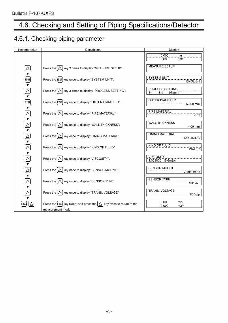
4.6. Checking and Setting of Piping Specifications/Detector
4.6.1. Checking piping parameter
Key operation Description Display
0.000 m/s
0.000 m3/h
Press the key 3 times to display “MEASURE SETUP”. MEASURE SETUP
ENT Press the ENT key once to display “SYSTEM UNIT”. SYSTEM UNIT
ENGLISH
Press the key 3 times to display “PROCESS SETTING”. PROCESS SETTING
S= 31( 93mm)
ENT Press the ENT key once to display “OUTER DIAMETER”. OUTER DIAMETER
60.00 mm
Press the key once to display “PIPE MATERIAL”. PIPE MATERIAL
PVC
Press the key once to display “WALL THICKNESS”. WALL THICKNESS
4.00 mm
Press the key once to display “LINING MATERIAL”. LINING MATERIAL
NO LINING
Press the key once to display “KIND OF FLUID”. KIND OF FLUID
WATER
Press the key once to display “VISCOSITY”. VISCOSITY
1.003800 E-6m2/s
Press the key once to display “SENSOR MOUNT”. SENSOR MOUNT
V METHOD
Press the key once to display “SENSOR TYPE”. SENSOR TYPE
SX1-A
Press the key once to display “TRANS. VOLTAGE”. TRANS. VOLTAGE
80 Vpp
ESC Press the ESC key twice, and press the key twice to return to the
measurement mode.
0.000 m/s
0.000 m3/h
Bulletin F-107-UXF3
-29-
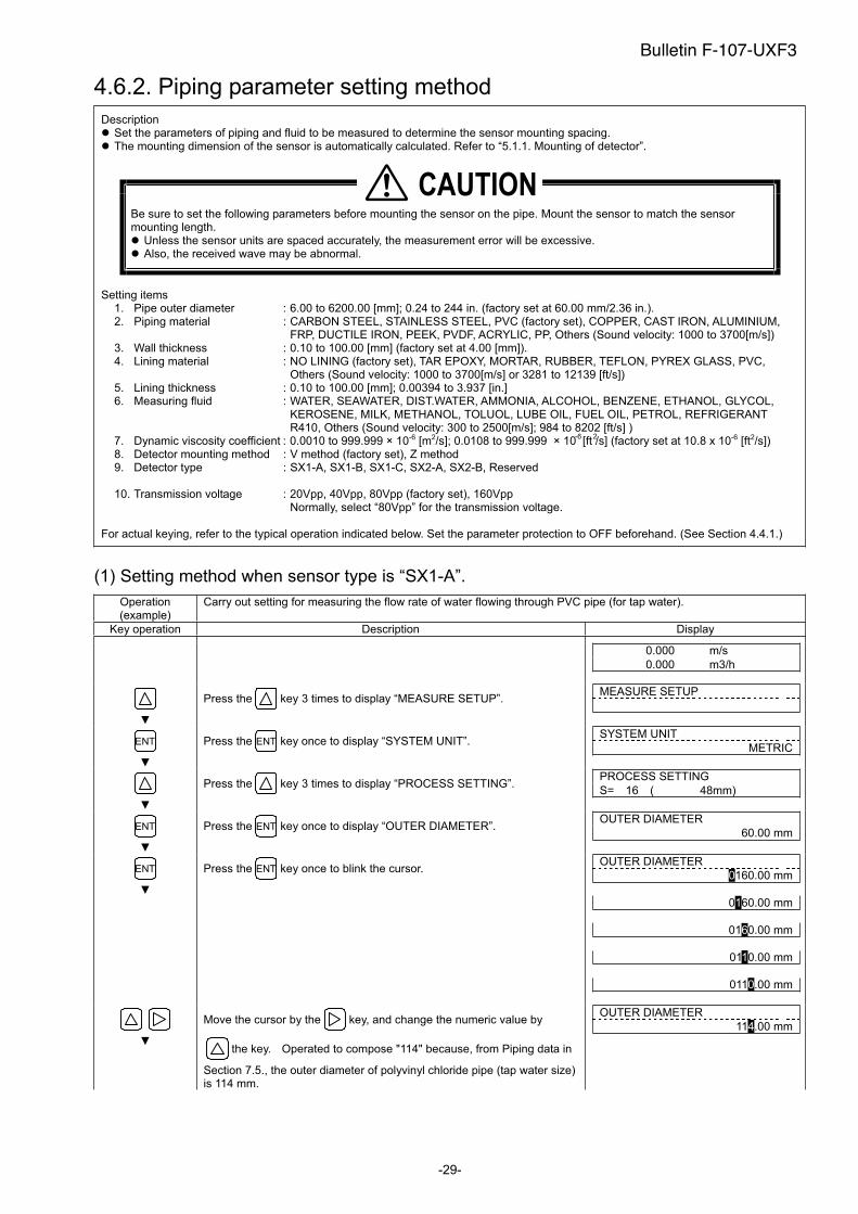
4.6.2. Piping parameter setting method
Description Set the parameters of piping and fluid to be measured to determine the sensor mounting spacing. The mounting dimension of the sensor is automatically calculated. Refer to “5.1.1. Mounting of detector”.
Be sure to set the following parameters before mounting the sensor on the pipe. Mount the sensor to match the sensor mounting length.
Unless the sensor units are spaced accurately, the measurement error will be excessive. Also, the received wave may be abnormal.
Setting items 1. Pipe outer diameter : 6.00 to 6200.00 [mm]; 0.24 to 244 in. (factory set at 60.00 mm/2.36 in.). 2. Piping material : CARBON STEEL, STAINLESS STEEL, PVC (factory set), COPPER, CAST IRON, ALUMINIUM,
FRP, DUCTILE IRON, PEEK, PVDF, ACRYLIC, PP, Others (Sound velocity: 1000 to 3700[m/s]) 3. Wall thickness : 0.10 to 100.00 [mm] (factory set at 4.00 [mm]). 4. Lining material : NO LINING (factory set), TAR EPOXY, MORTAR, RUBBER, TEFLON, PYREX GLASS, PVC,
Others (Sound velocity: 1000 to 3700[m/s] or 3281 to 12139 [ft/s])5. Lining thickness : 0.10 to 100.00 [mm]; 0.00394 to 3.937 [in.]6. Measuring fluid : WATER, SEAWATER, DIST.WATER, AMMONIA, ALCOHOL, BENZENE, ETHANOL, GLYCOL,
KEROSENE, MILK, METHANOL, TOLUOL, LUBE OIL, FUEL OIL, PETROL, REFRIGERANT R410, Others (Sound velocity: 300 to 2500[m/s]; 984 to 8202 [ft/s] )
7. Dynamic viscosity coefficient : 0.0010 to 999.999 × 10⁻⁶ [m2/s]; 0.0108 to 999.999 × 10 [ft /s] (factory set at 10.8 x 10⁻⁶ [ft2/s])8. Detector mounting method : V method (factory set), Z method 9. Detector type : SX1-A, SX1-B, SX1-C, SX2-A, SX2-B, Reserved
10. Transmission voltage : 20Vpp, 40Vpp, 80Vpp (factory set), 160Vpp Normally, select “80Vpp” for the transmission voltage.
For actual keying, refer to the typical operation indicated below. Set the parameter protection to OFF beforehand. (See Section 4.4.1.)
(1) Setting method when sensor type is “SX1-A”.
Operation (example)
Carry out setting for measuring the flow rate of water flowing through PVC pipe (for tap water).
Key operation Description Display
0.000 m/s
0.000 m3/h
Press the key 3 times to display “MEASURE SETUP”. MEASURE SETUP
ENT Press the ENT key once to display “SYSTEM UNIT”. SYSTEM UNIT
METRIC
Press the key 3 times to display “PROCESS SETTING”. PROCESS SETTING
S= 16 ( 48mm)
ENT Press the ENT key once to display “OUTER DIAMETER”. OUTER DIAMETER
60.00 mm
ENT Press the ENT key once to blink the cursor. OUTER DIAMETER
0160.00 mm
0160.00 mm
0160.00 mm
0110.00 mm
0110.00 mm
Move the cursor by the key, and change the numeric value by
the key. Operated to compose "114" because, from Piping data in
Section 7.5., the outer diameter of polyvinyl chloride pipe (tap water size) is 114 mm.
OUTER DIAMETER
114.00 mm
�������
Bulletin F-107-UXF3
2-6
-30-
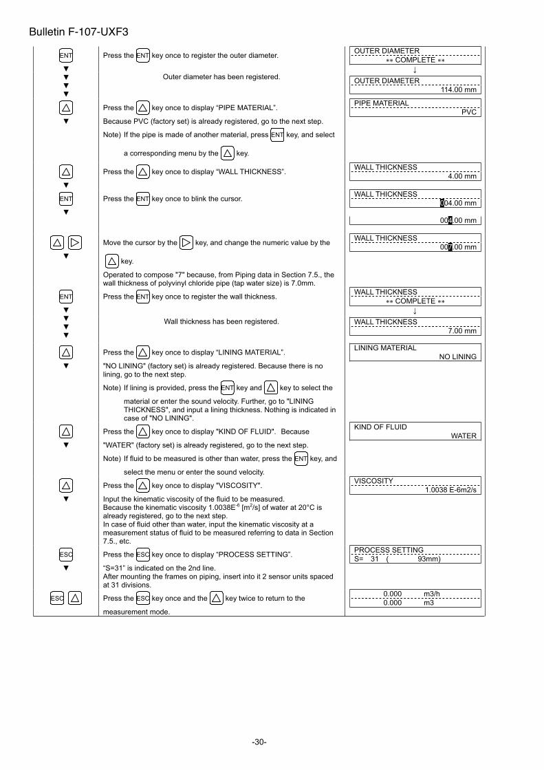
Press the ENT key once to register the outer diameter. ENT
Outer diameter has been registered.
OUTER DIAMETER
COMPLETE
OUTER DIAMETER
114.00 mm
Press the key once to display “PIPE MATERIAL”.
Because PVC (factory set) is already registered, go to the next step.
Note) If the pipe is made of another material, press ENT key, and select
a corresponding menu by the key.
PIPE MATERIAL
PVC
Press the key once to display “WALL THICKNESS”. WALL THICKNESS
4.00 mm
ENT Press the ENT key once to blink the cursor. WALL THICKNESS
004.00 mm
004.00 mm
Move the cursor by the key, and change the numeric value by the
key.
Operated to compose "7" because, from Piping data in Section 7.5., the wall thickness of polyvinyl chloride pipe (tap water size) is 7.0mm.
WALL THICKNESS
007.00 mm
Press the ENT key once to register the wall thickness. WALL THICKNESS
COMPLETE ENT
Wall thickness has been registered. WALL THICKNESS
7.00 mm
Press the key once to display “LINING MATERIAL”.
"NO LINING" (factory set) is already registered. Because there is no lining, go to the next step.
Note) If lining is provided, press the ENT key and key to select the
material or enter the sound velocity. Further, go to "LINING THICKNESS", and input a lining thickness. Nothing is indicated in case of "NO LINING".
LINING MATERIAL
NO LINING
Press the key once to display "KIND OF FLUID". Because
"WATER" (factory set) is already registered, go to the next step.
Note) If fluid to be measured is other than water, press the ENT key, and
select the menu or enter the sound velocity.
KIND OF FLUID
WATER
Press the key once to display "VISCOSITY".
Input the kinematic viscosity of the fluid to be measured. Because the kinematic viscosity 1.0038E-6 [m2/s] of water at 20°C is already registered, go to the next step. In case of fluid other than water, input the kinematic viscosity at a measurement status of fluid to be measured referring to data in Section 7.5., etc.
VISCOSITY
1.0038 E-6m2/s
ESC Press the ESC key once to display “PROCESS SETTING”.
“S=31” is indicated on the 2nd line. After mounting the frames on piping, insert into it 2 sensor units spaced at 31 divisions.
PROCESS SETTING
S= 31 ( 93mm)
ESC Press the ESC key once and the key twice to return to the
measurement mode.
0.000 m3/h
0.000 m3
Bulletin F-107-UXF3
- 31 -
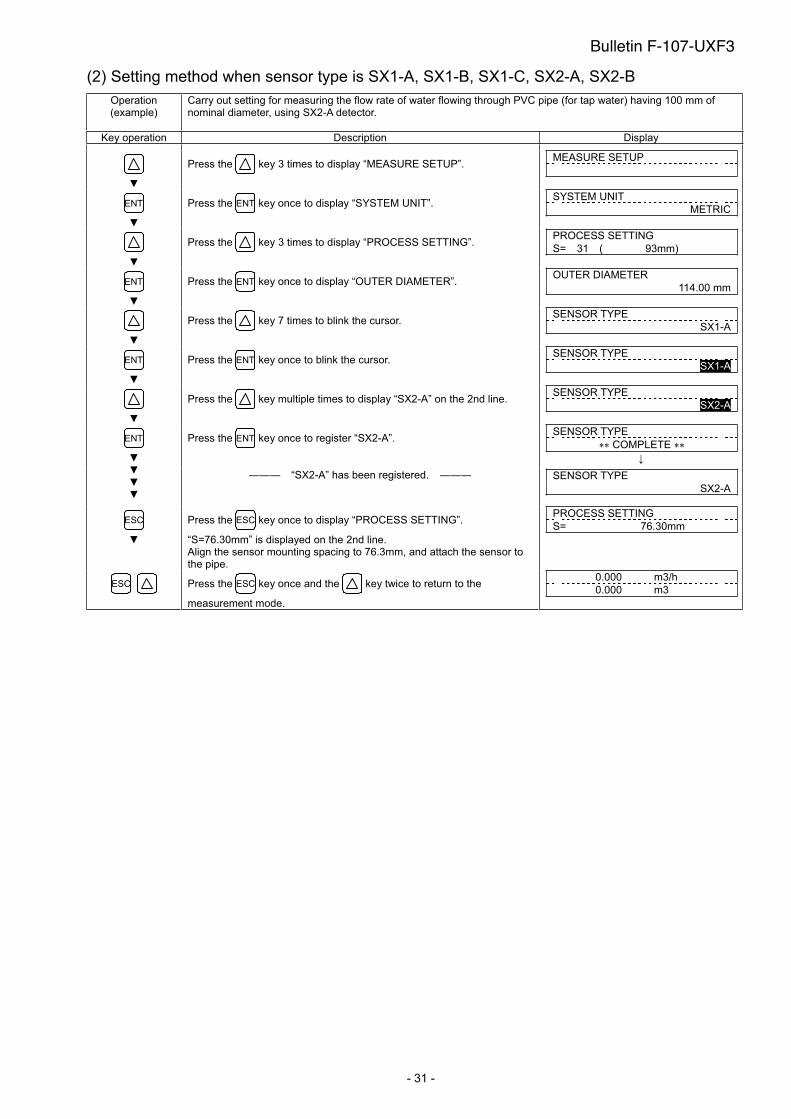
(2) Setting method when sensor type is SX1-A, SX1-B, SX1-C, SX2-A, SX2-B
Operation (example)
Carry out setting for measuring the flow rate of water flowing through PVC pipe (for tap water) having 100 mm of nominal diameter, using SX2-A detector.
Key operation Description Display
Press the key 3 times to display “MEASURE SETUP”. MEASURE SETUP
ENT Press the ENT key once to display “SYSTEM UNIT”. SYSTEM UNIT
METRIC
Press the key 3 times to display “PROCESS SETTING”. PROCESS SETTING
S= 31 ( 93mm)
ENT Press the ENT key once to display “OUTER DIAMETER”. OUTER DIAMETER
114.00 mm
Press the key 7 times to blink the cursor. SENSOR TYPE
SX1-A
ENT Press the ENT key once to blink the cursor. SENSOR TYPE
SX1-A
Press the key multiple times to display “SX2-A” on the 2nd line. SENSOR TYPE
SX2-A
Press the ENT key once to register “SX2-A”. SENSOR TYPE
COMPLETE ENT
“SX2-A” has been registered. SENSOR TYPE
SX2-A
ESC Press the ESC key once to display “PROCESS SETTING”.
“S=76.30mm” is displayed on the 2nd line. Align the sensor mounting spacing to 76.3mm, and attach the sensor to the pipe.
PROCESS SETTING
S= 76.30mm
ESC Press the ESC key once and the key twice to return to the
measurement mode.
0.000 m3/h
0.000 m3
Bulletin F-107-UXF3
-32-
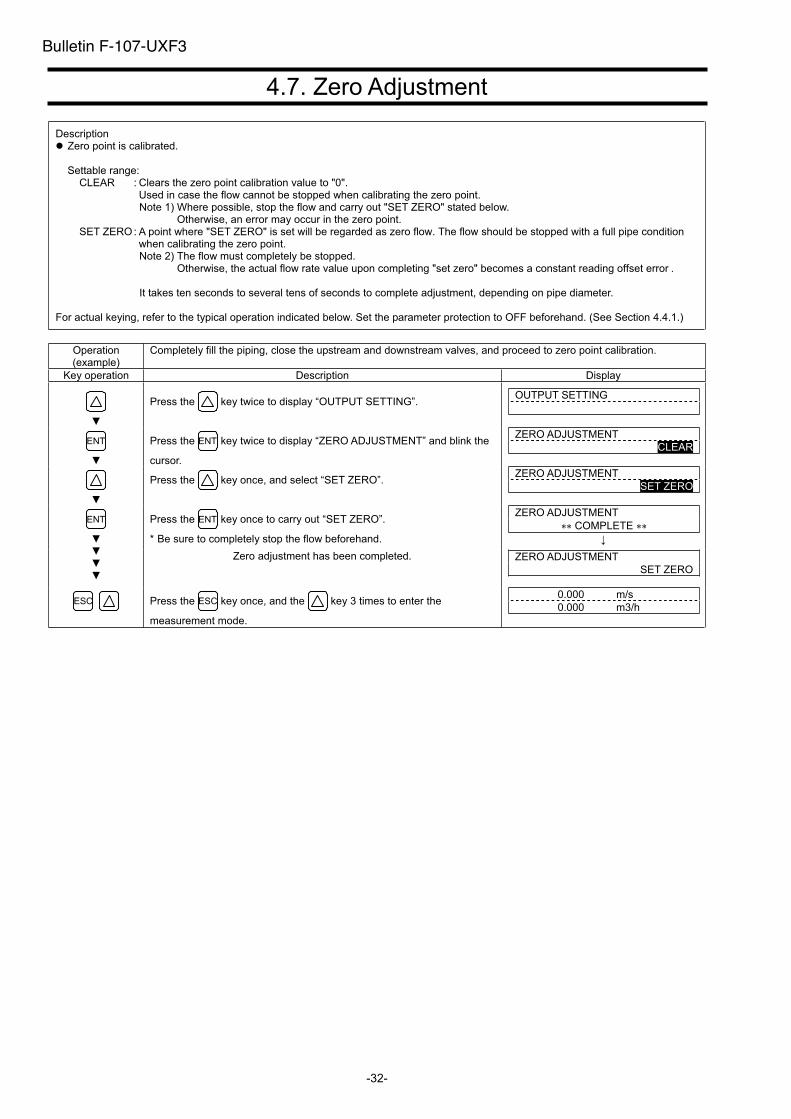
4.7. Zero Adjustment
Description Zero point is calibrated.
Settable range: CLEAR : Clears the zero point calibration value to "0".
Used in case the flow cannot be stopped when calibrating the zero point. Note 1) Where possible, stop the flow and carry out "SET ZERO" stated below.
Otherwise, an error may occur in the zero point. SET ZERO : A point where "SET ZERO" is set will be regarded as zero flow. The flow should be stopped with a full pipe condition
when calibrating the zero point. Note 2) The flow must completely be stopped.
Otherwise, the actual flow rate value upon completing "set zero" becomes a constant reading offset error .
It takes ten seconds to several tens of seconds to complete adjustment, depending on pipe diameter.
For actual keying, refer to the typical operation indicated below. Set the parameter protection to OFF beforehand. (See Section 4.4.1.)
Operation (example)
Completely fill the piping, close the upstream and downstream valves, and proceed to zero point calibration.
Key operation Description Display
Press the key twice to display “OUTPUT SETTING”. OUTPUT SETTING
ENT Press the ENT key twice to display “ZERO ADJUSTMENT” and blink the
cursor.
ZERO ADJUSTMENT
CLEAR
Press the key once, and select “SET ZERO”. ZERO ADJUSTMENT
SET ZERO
Press the ENT key once to carry out “SET ZERO”.
* Be sure to completely stop the flow beforehand.
ZERO ADJUSTMENT
COMPLETE ENT
Zero adjustment has been completed. ZERO ADJUSTMENT
SET ZERO
ESC Press the ESC key once, and the key 3 times to enter the
measurement mode.
0.000 m/s
0.000 m3/h
Bulletin F-107-UXF3
-33-
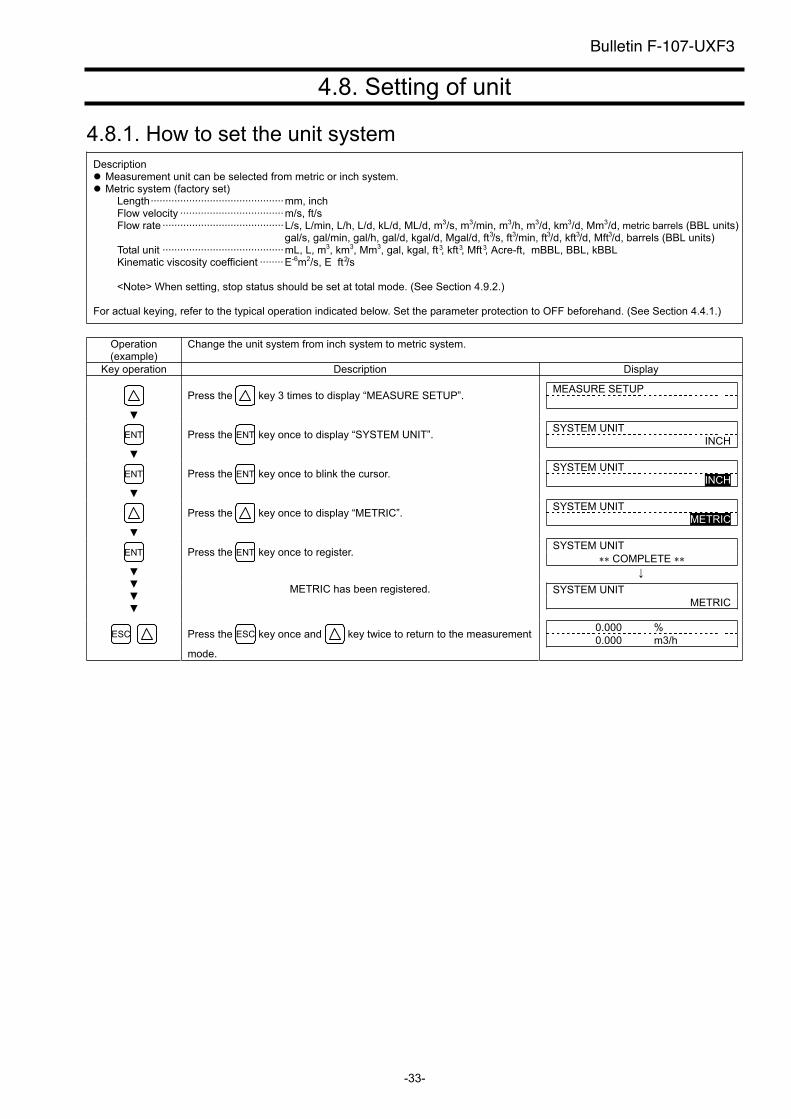
4.8. Setting of unit
4.8.1. How to set the unit system
Description Measurement unit can be selected from metric or inch system. Metric system (factory set)
Length·············································mm, inchFlow velocity ···································m/s, ft/sFlow rate ·········································L/s, L/min, L/h, L/d, kL/d, ML/d, m3/s, m3/min, m3/h, m3/d, km3/d, Mm3/d, metric barrels (BBL units)
gal/s, gal/min, gal/h, gal/d, kgal/d, Mgal/d, ft /s, ft /min, ft /d, kft /d, Mft /d, barrels (BBL units)Total unit ·········································mL, L, m3, km3, Mm3, gal, kgal, ft , kft , Mft , Acre-ft, mBBL, BBL, kBBLKinematic viscosity coefficient ········E-6m2/s, E ft /s
<Note> When setting, stop status should be set at total mode. (See Section 4.9.2.)
For actual keying, refer to the typical operation indicated below. Set the parameter protection to OFF beforehand. (See Section 4.4.1.)
Operation (example)
Change the unit system from inch system to metric system.
Key operation Description Display
Press the key 3 times to display “MEASURE SETUP”. MEASURE SETUP
ENT Press the ENT key once to display “SYSTEM UNIT”. SYSTEM UNIT
INCH
ENT Press the ENT key once to blink the cursor. SYSTEM UNIT
INCH
Press the key once to display “METRIC”. SYSTEM UNIT
METRIC
Press the ENT key once to register. SYSTEM UNIT
COMPLETE ENT
METRIC has been registered. SYSTEM UNIT
METRIC
ESC Press the ESC key once and key twice to return to the measurement
mode.
0.000 %
0.000 m3/h
Bulletin F-107-UXF3
333
33333
2
-34-
4.8.2. How to set the flow rate unit
Description Select the unit of flow rate. Metric system
Flow rate········· L/s, L/min, L/h, L/d, kL/d, ML/d, m3/s, m3/min, m3/h (factory set), m3/d, km3/d, Mm3/d, BBL/s, BBL/min, BBL/h, BBL/d, kBBL/d, MBBL/d, gal/s, gal/min, gal/h, gal/d, kgal/d, Mgal/d, ft /s, ft /min, ft /d, kft /d, Mft /d, barrels (BBL units)
<Note> First, set the unit system (metric) according to Section 4.8.1.
For actual keying, refer to the typical operation indicated below. Set the parameter protection to OFF beforehand. (See Section 4.4.1.)
Operation (example)
Set a flow rate unit to “L/min”.
Key operation Description Display
Press the key 3 times to display “MEASURE SETUP”. MEASURE SETUP
ENT Press the ENT key once to display “SYSTEM UNIT”. SYSTEM UNIT
METRIC
Press the key once to display “FLOW UNIT”. FLOW UNIT
m3/h
ENT Press the ENT key once to blink the cursor. FLOW UNIT
m3/h
Press the key several times to display “L/min”. FLOW UNIT
L/min
Press the ENT key once to register. FLOW UNIT
COMPLETE ENT
“L/min” has been registered. FLOW UNIT
L/min
ESC Press the ESC key once and the key twice to return to the
measurement mode.
0.000 m/s
0.000 L/min
Bulletin F-107-UXF3
3 3333
-35-
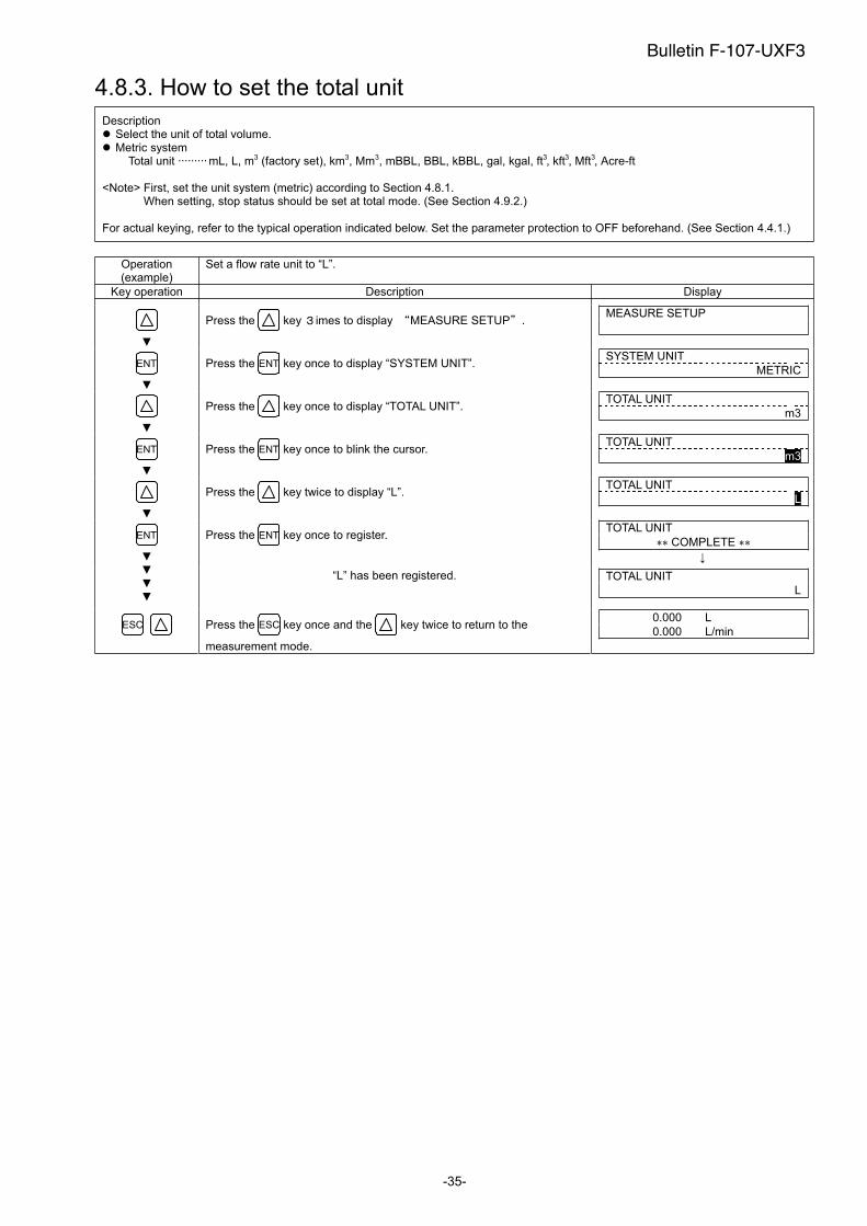
4.8.3. How to set the total unit
Description Select the unit of total volume. Metric system
Total unit ········· mL, L, m3 (factory set), km3, Mm3, mBBL, BBL, kBBL, gal, kgal, ft , kft , Mft , Acre-ft
<Note> First, set the unit system (metric) according to Section 4.8.1. When setting, stop status should be set at total mode. (See Section 4.9.2.)
For actual keying, refer to the typical operation indicated below. Set the parameter protection to OFF beforehand. (See Section 4.4.1.)
Operation (example)
Set a flow rate unit to “L”.
Key operation Description Display
Press the key imes to display MEASURE SETUP .MEASURE SETUP
ENT Press the ENT key once to display “SYSTEM UNIT”. SYSTEM UNIT
METRIC
Press the key once to display “TOTAL UNIT”. TOTAL UNIT
m3
ENT Press the ENT key once to blink the cursor. TOTAL UNIT
m3
Press the key twice to display “L”. TOTAL UNIT
L
Press the ENT key once to register. TOTAL UNIT
COMPLETE ENT
“L” has been registered. TOTAL UNIT
L
ESC Press the ESC key once and the key twice to return to the
measurement mode.
0.000 L
0.000 L/min
Bulletin F-107-UXF3
3 33
-36-
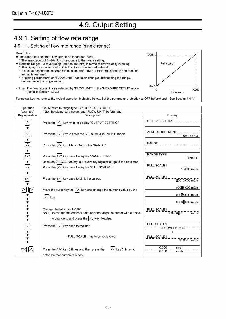
4.9. Output Setting
4.9.1. Setting of flow rate range
4.9.1.1. Setting of flow rate range (single range)
Description The range (full scale) of flow rate to be measured is set. * The analog output (4-20mA) corresponds to the range setting.
Settable range: 0.3 to 32 [m/s]; 0.984 to 105 [ft/s] in terms of flow velocity in piping * The piping parameters and FLOW UNIT must be set beforehand. * If a value beyond the settable range is inputted, "INPUT ERROR" appears and then last
setting is resumed. * If "piping parameters" or "FLOW UNIT" has been changed after setting the range,
recommence the range setting.
<Note> The flow rate unit is as selected by "FLOW UNIT" in the "MEASURE SETUP" mode. (Refer to Section 4.8.2.)
For actual keying, refer to the typical operation indicated below. Set the parameter protection to OFF beforehand. (See Section 4.4.1.)
Operation (example)
Set 60m3/h to range type, SINGLE/FULL SCALE1. * Set the piping parameters and "FLOW UNIT" beforehand.
Key operation Description Display
Press the key twice to display “OUTPUT SETTING”. OUTPUT SETTING
ENT Press the ENT key to enter the “ZERO ADJUSTMENT” mode. ZERO ADJUSTMENT
SET ZERO
Press the key 4 times to display “RANGE”. RANGE
ENT Press the ENT key once to display “RANGE TYPE”.
Because SINGLE (factory set) is already registered, go to the next step.
RANGE TYPE
SINGLE
Press the key once to display “FULL SCALE1”. FULL SCALE1
15.000 m3/h
ENT Press the ENT key once to blink the cursor. FULL SCALE1
00015.000 m3/h
Move the cursor by the key, and change the numeric value by the
key.
00015.000 m3/h
00065.000 m3/h
00065.000 m3/h
Change the full scale to “60”. Note) To change the decimal point position, align the cursor with a place
to change to and press the key likewise.
FULL SCALE1
0000060.0 m3/h
Press the ENT key once to register. FULL SCALE1
COMPLETE ENT
FULL SCALE1 has been registered. FULL SCALE1
60.000 m3/h
ESC Press the ESC key 3 times and then press the key 3 times to
enter the measurement mode.
0.000 m/s
0.000 m3/h
20mA
4mA
0 100%Flow rate
Full scale 1
Bulletin F-107-UXF3
-37-
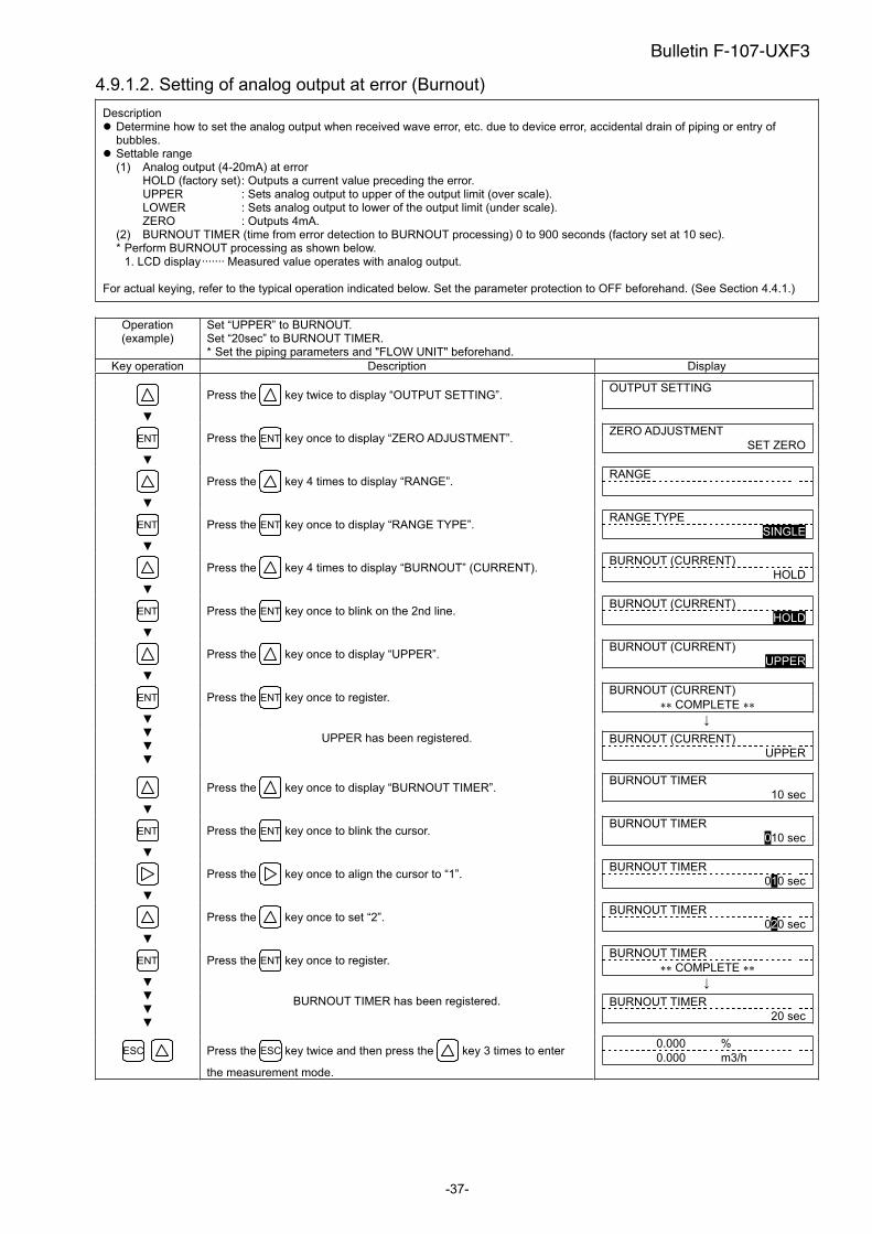
4.9.1.2. Setting of analog output at error (Burnout)
Description Determine how to set the analog output when received wave error, etc. due to device error, accidental drain of piping or entry of bubbles.
Settable range (1) Analog output (4-20mA) at error
HOLD (factory set) : Outputs a current value preceding the error. UPPER : Sets analog output to upper of the output limit (over scale). LOWER : Sets analog output to lower of the output limit (under scale). ZERO : Outputs 4mA.
(2) BURNOUT TIMER (time from error detection to BURNOUT processing) 0 to 900 seconds (factory set at 10 sec). * Perform BURNOUT processing as shown below.
1. LCD display······· Measured value operates with analog output.
For actual keying, refer to the typical operation indicated below. Set the parameter protection to OFF beforehand. (See Section 4.4.1.)
Operation (example)
Set “UPPER” to BURNOUT. Set “20sec” to BURNOUT TIMER. * Set the piping parameters and "FLOW UNIT" beforehand.
Key operation Description Display
Press the key twice to display “OUTPUT SETTING”. OUTPUT SETTING
ENT Press the ENT key once to display “ZERO ADJUSTMENT”. ZERO ADJUSTMENT
SET ZERO
Press the key 4 times to display “RANGE”. RANGE
ENT Press the ENT key once to display “RANGE TYPE”. RANGE TYPE
SINGLE
Press the key 4 times to display “BURNOUT” (CURRENT). BURNOUT (CURRENT)
HOLD
ENT Press the ENT key once to blink on the 2nd line. BURNOUT (CURRENT)
HOLD
Press the key once to display “UPPER”. BURNOUT (CURRENT)
UPPER
Press the ENT key once to register. BURNOUT (CURRENT)
COMPLETE ENT
UPPER has been registered. BURNOUT (CURRENT)
UPPER
Press the key once to display “BURNOUT TIMER”. BURNOUT TIMER
10 sec
ENT Press the ENT key once to blink the cursor. BURNOUT TIMER
010 sec
Press the key once to align the cursor to “1”. BURNOUT TIMER
010 sec
Press the key once to set “2”. BURNOUT TIMER
020 sec
Press the ENT key once to register. BURNOUT TIMER
COMPLETE ENT
BURNOUT TIMER has been registered. BURNOUT TIMER
20 sec
ESC Press the ESC key twice and then press the key 3 times to enter
the measurement mode.
0.000 %
0.000 m3/h
Bulletin F-107-UXF3
-38-
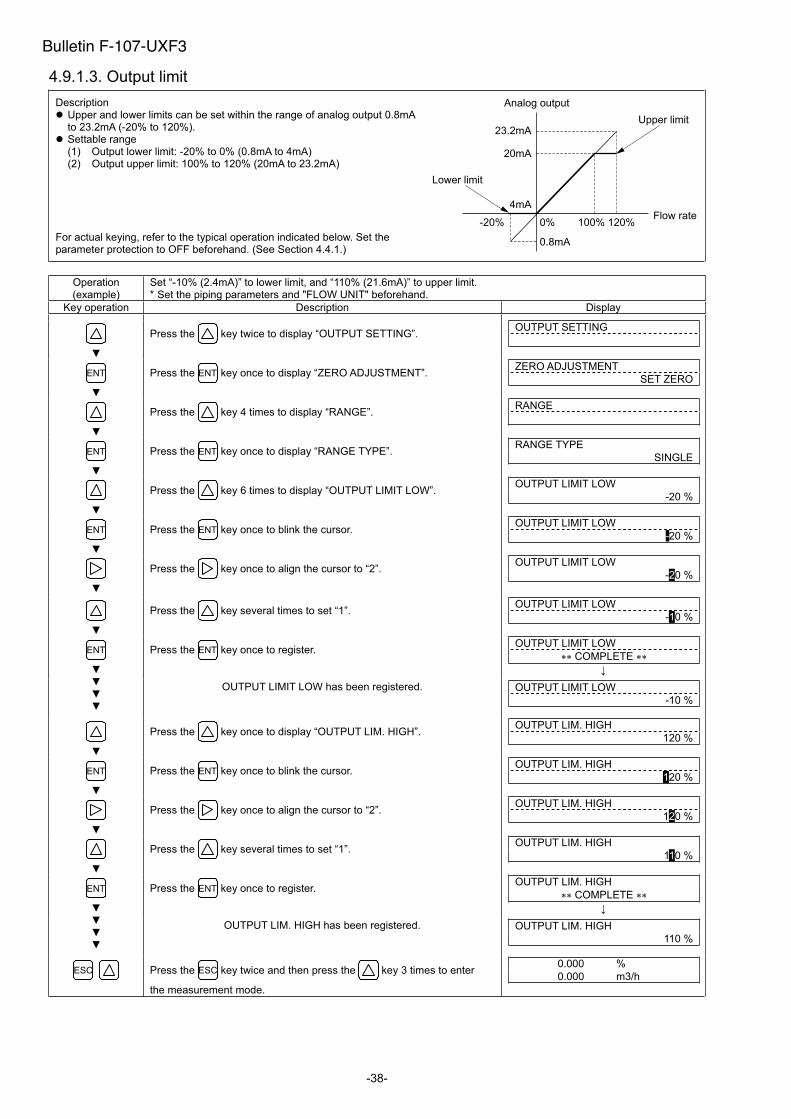
4.9.1.3. Output limit
Description Upper and lower limits can be set within the range of analog output 0.8mA to 23.2mA (-20% to 120%).
Settable range (1) Output lower limit: -20% to 0% (0.8mA to 4mA) (2) Output upper limit: 100% to 120% (20mA to 23.2mA)
For actual keying, refer to the typical operation indicated below. Set the parameter protection to OFF beforehand. (See Section 4.4.1.)
Operation (example)
Set “-10% (2.4mA)” to lower limit, and “110% (21.6mA)” to upper limit. * Set the piping parameters and "FLOW UNIT" beforehand.
Key operation Description Display
Press the key twice to display “OUTPUT SETTING”. OUTPUT SETTING
ENT Press the ENT key once to display “ZERO ADJUSTMENT”. ZERO ADJUSTMENT
SET ZERO
Press the key 4 times to display “RANGE”. RANGE
ENT Press the ENT key once to display “RANGE TYPE”. RANGE TYPE
SINGLE
Press the key 6 times to display “OUTPUT LIMIT LOW”. OUTPUT LIMIT LOW
-20 %
ENT Press the ENT key once to blink the cursor. OUTPUT LIMIT LOW
-20 %
Press the key once to align the cursor to “2”. OUTPUT LIMIT LOW
-20 %
Press the key several times to set “1”. OUTPUT LIMIT LOW
-10 %
Press the ENT key once to register. OUTPUT LIMIT LOW
COMPLETE ENT
OUTPUT LIMIT LOW has been registered. OUTPUT LIMIT LOW
-10 %
Press the key once to display “OUTPUT LIM. HIGH”. OUTPUT LIM. HIGH
120 %
ENT Press the ENT key once to blink the cursor. OUTPUT LIM. HIGH
120 %
Press the key once to align the cursor to “2”. OUTPUT LIM. HIGH
120 %
Press the key several times to set “1”. OUTPUT LIM. HIGH
110 %
Press the ENT key once to register. OUTPUT LIM. HIGH
COMPLETE ENT
OUTPUT LIM. HIGH has been registered. OUTPUT LIM. HIGH
110 %
ESC Press the ESC key twice and then press the key 3 times to enter
the measurement mode.
0.000 %
0.000 m3/h
Analog output
20mA
23.2mA
4mA
0%
0.8mA
-20% 100% 120%
Lower limit
Upper limit
Flow rate
Bulletin F-107-UXF3
-39-
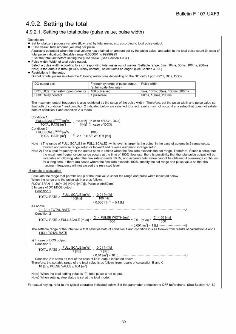
4.9.2. Setting the total
4.9.2.1. Setting the total pulse (pulse value, pulse width)
Description Set to totalize a process variable (flow rate) by total meter, etc. according to total pulse output. Pulse value: Total amount (volume) per pulse. A pulse is outputted when the total volume has attained an amount set by the pulse value, and adds to the total pulse count (in case of total pulse indication). Settable range: 0.000001 to 99999999 * Set the total unit before setting the pulse value. (See Section 4.8.3.)
Pulse width: Width of total pulse output. Select a pulse width according to a corresponding total meter out of menus. Settable range: 5ms, 10ms, 50ms, 100ms, 200ms Note) If the output is through DO2 (relay contact), select 50ms or longer. (See Section 4.9.3.)
Restrictions in the setup Output of total pulses involves the following restrictions depending on the DO output port (DO1, DO2, DO3).
DO output port Frequency range of pulse output (at full scale flow rate)
Pulse width
DO1, DO2: Transistor, open collector 100 pulse/sec 5ms, 10ms, 50ms, 100ms, 200ms
DO3: Relay contact 1 pulse/sec 50ms, 100ms, 200ms
The maximum output frequency is also restricted by the setup of the pulse width. Therefore, set the pulse width and pulse value so that both of condition 1 and condition 2 indicated below are satisfied. Correct results may not occur, if any setup that does not satisfy both of condition 1 and condition 2 is made.
Condition 1: FULL SCALE
(Note1) [m
3/s]
TOTAL RATE [m3]
100[Hz]1[Hz]
(In case of DO1, DO2)(In case of DO3)
Condition 2: FULL SCALE
(Note1) [m
3/s]
TOTAL RATE [m3]
1000 2 × PULSE WIDTH [ms]
Note 1) The range of FULL SCALE1 or FULL SCALE2, whichever is larger, is the object in the case of automatic 2-range setup, forward and reverse range setup or forward and reverse automatic 2-range setup.
Note 2) The output frequency on the output ports is limited when the flow rate exceeds the set range. Therefore, if such a setup that the maximum frequency per range occurs at the time of 100% flow rate, there is possibility that the total pulse output will be incapable of following when the flow rate exceeds 100%, and accurate total value cannot be obtained if over-range continues for a long time. If there are cases where the flow rate exceeds 100%, modify the set range and pulse value so that the maximum frequency will not exceed the restricted level.
Example of calculation
Calculate the range that permits setup of the total value under the range and pulse width indicated below. When the range and the pulse width are as follows.
FLOW SPAN -1: 36[m3/h] (=0.01[m
3/s]), Pulse width:50[ms]
i) In case of DO1/DO2 output Condition 1
TOTAL RATE FULL SCALE [m
3/s]
100[Hz] =
0.01 [m3/s]
100 [Hz]
= 0.0001 [m3] = 0.1 [L]
As above:
0.1 [L] TOTAL RATE ··································································································································A
Condition 2
TOTAL RATE FULL SCALE [m3/s] ×
2 PULSE WIDTH [ms]
1000 = 0.01 [m
3/s] ×
2 50 [ms]
1000
= 0.001 [m3] = 1 [L] ·····························B
The settable range of the total value that satisfies both of condition 1 and condition 2 is as follows from results of calculation A and B.
1 [L] TOTAL RATE
ii) In case of DO3 output Condition 1
TOTAL RATE FULL SCALE [m
3/s]
1 [Hz] =
0.01 [m3/s]
1 [Hz]
= 0.01 [m3] = 10 [L] ········································································C
Condition 2 is same as that of the case of DO1 output indicated above. Therefore, the settable range of the total value is as follows from results of calculation B and C.
10 [L] PULSE VALUE 864 [m3]
Note) When the total setting value is “0”, total pulse is not output. Note) When setting, stop status is set at the total mode.
For actual keying, refer to the typical operation indicated below. Set the parameter protection to OFF beforehand. (See Section 4.4.1.)
Bulletin F-107-UXF3
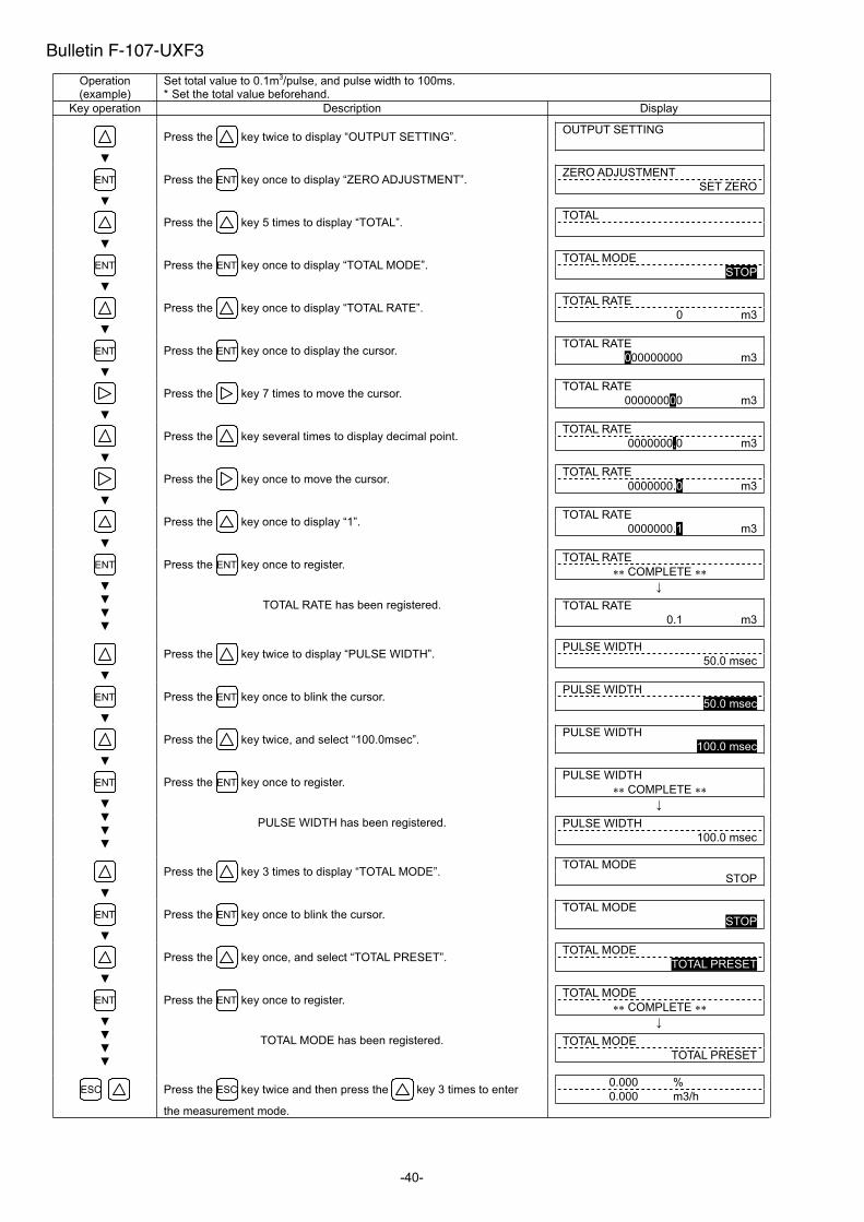
-40-
Operation (example)
Set total value to 0.1m3/pulse, and pulse width to 100ms. * Set the total value beforehand.
Key operation Description Display
Press the key twice to display “OUTPUT SETTING”. OUTPUT SETTING
ENT Press the ENT key once to display “ZERO ADJUSTMENT”. ZERO ADJUSTMENT
SET ZERO
Press the key 5 times to display “TOTAL”. TOTAL
ENT Press the ENT key once to display “TOTAL MODE”. TOTAL MODE
STOP
Press the key once to display “TOTAL RATE”. TOTAL RATE
0 m3
ENT Press the ENT key once to display the cursor. TOTAL RATE
000000000 m3
Press the key 7 times to move the cursor. TOTAL RATE
000000000 m3
Press the key several times to display decimal point. TOTAL RATE
0000000.0 m3
Press the key once to move the cursor. TOTAL RATE
0000000.0 m3
Press the key once to display “1”. TOTAL RATE
0000000.1 m3
Press the ENT key once to register. TOTAL RATE
COMPLETE ENT
TOTAL RATE has been registered. TOTAL RATE
0.1 m3
Press the key twice to display “PULSE WIDTH”. PULSE WIDTH
50.0 msec
ENT Press the ENT key once to blink the cursor. PULSE WIDTH
50.0 msec
Press the key twice, and select “100.0msec”. PULSE WIDTH
100.0 msec
Press the ENT key once to register. PULSE WIDTH
COMPLETE ENT
PULSE WIDTH has been registered. PULSE WIDTH
100.0 msec
Press the key 3 times to display “TOTAL MODE”. TOTAL MODE
STOP
ENT Press the ENT key once to blink the cursor. TOTAL MODE
STOP
Press the key once, and select “TOTAL PRESET”. TOTAL MODE
TOTAL PRESET
Press the ENT key once to register. TOTAL MODE
COMPLETE ENT
TOTAL MODE has been registered. TOTAL MODE
TOTAL PRESET
ESC Press the ESC key twice and then press the key 3 times to enter
the measurement mode.
0.000 %
0.000 m3/h
Bulletin F-107-UXF3
-41-
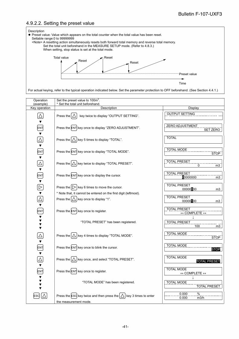
4.9.2.2. Setting the preset value
Description Preset value: Value which appears on the total counter when the total value has been reset. Settable range:0 to 99999999 <Note> A resetting action simultaneously resets both forward total memory and reverse total memory.
Set the total unit beforehand in the MEASURE SETUP mode. (Refer to 4.8.3.) When setting, stop status is set at the total mode.
Total value
Preset value
Time
ResetReset
Reset
For actual keying, refer to the typical operation indicated below. Set the parameter protection to OFF beforehand. (See Section 4.4.1.)
Operation (example)
Set the preset value to 100m3.* Set the total unit beforehand.
Key operation Description Display
Press the key twice to display “OUTPUT SETTING”. OUTPUT SETTING
ENT Press the ENT key once to display “ZERO ADJUSTMENT”. ZERO ADJUSTMENT
SET ZERO
Press the key 5 times to display “TOTAL”. TOTAL
ENT Press the ENT key once to display “TOTAL MODE”. TOTAL MODE
STOP
Press the key twice to display “TOTAL PRESET”. TOTAL PRESET
0 m3
ENT Press the ENT key once to display the cursor. TOTAL PRESET
00000000 m3
Press the key 6 times to move the cursor.
* Note that, it cannot be entered on the first digit (leftmost).
TOTAL PRESET
00000000 m3
Press the key once to display “1”. TOTAL PRESET
00000100 m3
Press the ENT key once to register. TOTAL PRESET
COMPLETE ENT
“TOTAL PRESET” has been registered. TOTAL PRESET
100 m3
Press the key 4 times to display “TOTAL MODE”. TOTAL MODE
STOP
ENT Press the ENT key once to blink the cursor. TOTAL MODE
STOP
Press the key once, and select “TOTAL PRESET”. TOTAL MODE
TOTAL PRESET
Press the ENT key once to register. TOTAL MODE
COMPLETE ENT
“TOTAL MODE” has been registered. TOTAL MODE
TOTAL PRESET
ESC Press the ESC key twice and then press the key 3 times to enter
the measurement mode.
0.000 %
0.000 m3/h
Bulletin F-107-UXF3

-42-
4.9.2.3. TOTAL mode (total reset, start, stop)
Description The total is started, stopped or reset. Settable range: START, STOP, TOTAL RESET START : Starts totalizing. Totalizes continuously from the stopped status. STOP : Stops totalizing. Setting cannot be changed when it is not stopped. RESET : Resets the total memory to the preset value, and starts totalizing. <Note> A resetting action simultaneously resets both forward total memory and reverse total memory.
For actual keying, refer to the typical operation indicated below. Set the parameter protection to OFF beforehand. (See Section 4.4.1.)
Operation (example)
Reset the total value (preset value 0m3), and restart a total.
Key operation Description Display
0.00 m3/h
+ 127.26 m3
Press the key twice to display “OUTPUT SETTING”. OUTPUT SETTING
ENT Press the ENT key once to display “ZERO ADJUSTMENT”. ZERO ADJUSTMENT
SET ZERO
Press the key 5 times to display “TOTAL”. TOTAL
ENT Press the ENT key once to display “TOTAL MODE”. TOTAL MODE
START
ENT Press the ENT key once to blink the cursor. TOTAL MODE
START
Press the key twice to display “TOTAL RESET”. TOTAL MODE
TOTAL PRESET
Press the ENT key twice to execute “TOTAL RESET”. TOTAL MODE
COMPLETE ENT
The total operation is started. TOTAL MODE
TOTAL PRESET
ESC Press the ESC key twice and then press the key 3 times to enter
the measurement mode.
0.00 m3/h
0.00 m3
Bulletin F-107-UXF3
-43-
4.9.2.4. Determining how to dispose of total at error (BURNOUT)
Description BURNOUT (TOTAL)
Determines how to dispose of the total when the measurement status is abnormal on account of an empty pipe interior or bubblesmixed in fluid (common to total indication and total pulse output).
Settable range: HOLD : Stops the total (as factory set). NOT USED : Continues the total according to a flow rate marked immediately before the error occurrence.
BURNOUT TIMER Sets the time from error occurrence to error processing. Settable range: 0 to 900sec (factory set: 10sec) The total continues until the burnout timer is actuated.
For actual keying, refer to the typical operation indicated below. Set the parameter protection to OFF beforehand. (See Section 4.4.1.)
Operation (example)
Change the processing from "BURNOUT" to "HOLD", and change the burnout timer setting from 10 seconds to 15 seconds.
Key operation Description Display
Press the key twice to display “OUTPUT SETTING”. OUTPUT SETTING
ENT Press the ENT key once to display “ZERO ADJUSTMENT”. ZERO ADJUSTMENT
SET ZERO
Press the key 5 times to display “TOTAL”. TOTAL
ENT Press the ENT key once to display “TOTAL MODE”. TOTAL MODE
START
Press the key 4 times to display “BURNOUT(TOTAL)”.
Because HOLD (factory set) is already registered, go to the next step.
BURNOUT(TOTAL)
HOLD
Note) For setting “NOT USED”, press the key, and the key to select “NOT USED”.
Press the key once to display “BURNOUT TIMER”. BURNOUT TIMER
10sec
ENT Press the ENT key once to blink the cursor. BURNOUT TIMER
010sec
Press the key twice to move the cursor. BURNOUT TIMER
010sec
Press the key 5 times to set “5”. BURNOUT TIMER
015sec
Press the ENT key once to register. BURNOUT TIMER
COMPLETE ENT
BURNOUT TIMER has been registered. BURNOUT TIMER
15sec
ESC Press the ESC key twice and then press the key 3 times to enter
the measurement mode.
0.00 m3/h
+ 0.00 m3
ENT
Bulletin F-107-UXF3
-44-
4.9.3. Setting the DO output
Description Selects the output of total pulses and statuses (of alarm, flow switch, total switch, etc.).
Settable range (common to DO1, DO2 and DO3) NOT USED : Does not use the contact output. +TOTAL PULSE : Outputs the forward total pulses. -TOTAL PULSE : Outputs total pulse in reverse direction. FULL SCALE 2 : Selects a contact output as FULL SCALE 2 measurement status.
(forward automatic 2 ranges, forward and reverse range, forward/reverse automatic 2 ranges) ALARM
ALL : Selects a contact output at HARDWARE FAULT or PROCESS ERROR status. HARDWARE FAULT : Selects a contact output when circuit error such as memory occurred. PROCESS ERROR : Selects a contact output when no waves are received, or waves are unstable.
FLOW SWITCH FLOW SW HIGH : Selects a contact output when flow rate is above the setting. FLOW SW LOW : Selects a contact output when flow rate is below the setting.
TOTAL SWITCH : Selects a contact output when total value exceeds the setting. AO RANGE OVER : Selects a contact output when the lower and upper limits of range are above the setting. PULSE RANGE OVER : Selects a contact output when the total pulse output exceeds the maximum output frequency. -FLOW DIRECTION : Selects a contact output when the flow is in reverse direction. CONTACT ACTION
ACTIVE ON : Normally off (DO1/DO2) or normal open (DO3). ACTIVE OFF : Normally on (DO1/DO2) or normal close (DO3).
If the contact action is set to “ACTIVE OFF”, DO output is provided when the power is turned on. Check if DO output can be modified before setting.
<Note> DO output specifications DO1/DO2 : Open collector, Contact capacity 30V DC, 0.1A
When total pulse output is selected (Note: See 4.9.2.1) 100 pulses/s or less (at full scale flow rate) Pulse width: 5, 10, 50, 100 or 200ms.
DO3 : Relay contact, Contact capacity 220V AC/30V DC, 1A Service life 200,000 times (under rated load), Can be replaced if provided with a socket. (See 6.4. How to replace the relay) When total pulse output is selected (Note: See 4.9.2.1) 1 pulse/s or less (at full scale flow rate) Pulse width: 50, 100 or 200ms.
For actual keying, refer to the typical operation indicated below. Set the parameter protection to OFF beforehand. (See Section 4.4.1.)
4.9.3.1. How to validate the total pulse output
Description Validates the total pulse output for DO1 OUT, DO2 OUT and/or DO3 OUT. +TOTAL PULSE : Outputs flow rate total pulse in forward direction. -TOTAL PULSE : Reverse flow rate total pulse output. Note) Referring to Section 4.9.2.1., set the pulse value, pulse width, etc.
For concrete keying, refer to the typical operation indicated below. Set the parameter protection to OFF beforehand. (See Section 4.4.1.)
Operation (example)
Set the DO1 output to “+ TOTAL PULSE”. Also, set the contact to “ACTIVE ON”.
Key operation Description Display
Press the key twice to display “OUTPUT SETTING”. OUTPUT SETTING
ENT Press the ENT key once to display “ZERO ADJUSTMENT”. ZERO ADJUSTMENT
SET ZERO
Press the key 6 times to display “DO1 OUT”.
* Press the key again to display “DO2 OUT”.
* Press the key once again to display “DO3 OUT”.
DO1 OUT
NOT USED
ENT Press the ENT key once to blink the cursor. DO1 OUT
NOT USED
�������
Bulletin F-107-UXF3
-45-
Press the key once to display “+TOTAL PULSE” on the 2nd line.
Press the key again to select “-TOTAL PULSE”.
DO1 OUT
+TOTAL PULSE
Press the ENT key once to register “+TOTAL PULSE”. DO1 OUT
COMPLETE ENT
“+TOTAL PULSE” has been registered. STATUS OUT
CONTACT ACTION
ENT Press the ENT key once to display “CONTACT ACTION”. CONTACT ACTION
ACTIVE ON
Press the ENT key once to register “ACTIVE ON” (normally off).
* To select normally on, press the key.
CONTACT ACTION
COMPLETE ENT
“ACTIVE ON” has been registered. STATUS OUT
CONTACT ACTION
ESC Press the ESC key twice and then press the key 3 times to enter
the measurement mode.
0.000 %
0.000 m3/h
Bulletin F-107-UXF3
-46-
4.9.4. Setting the LCD indication
Description Flow velocity indication Selectable flow velocity units: m/s (if SYSTEM UNIT was set to METRIC) (See 4.8.1) <Note> The decimal point position is fixed. (Decimal point 3 digits)
Flow rate indication Selectable flow rate indications: Actual value reading, % reading. <Note> The indication unit is as selected by FLOW UNIT. (See 4.8.2.)
Total indication Selectable total indications: Actual total value reading (forward/reverse flow), total pulse count (forward/reverse flow). <Note> The indication unit is as selected by TOTAL UNIT. (See 4.9.4.)
How to validate the indication Set the DISPLAY setting mode to 1st ROW (for indication on 1st line) or 2nd ROW (for indication on 2nd line), and further selectindication contents.
For actual keying, refer to the typical operation indicated below. Set the parameter protection to OFF beforehand. (See Section 4.4.1.)
Operation (example)
Display the 1st line of LCD indication in percentages (%).
Key operation Description Display
Press the key twice to display “OUTPUT SETTING”. OUTPUT SETTING
ENT Press the ENT key once to display “ZERO ADJUSTMENT”. ZERO ADJUSTMENT
SET ZERO
Press the key 3 times to display “DISPLAY”. DISPLAY
DISPLAY 1
ENT Press the ENT key once to blink the cursor. DISPLAY
DISPLAY 1
ENT Press the ENT key again, and select “1ST LOW”. 1ST LOW
VELOCITY
Press the key twice to display “FLOW RATE(%)”. 1ST LOW
FLOW RATE(%)
ENT Press the ENT key once, and select and fix “FLOW RATE(%)” to display
“1:DECIMAL POINT”.
1:DECIMAL POINT
.
Press the key once to shift the decimal point position to next place. 1:DECIMAL POINT
.
Press the ENT key once to register. 1:DECIMAL POINT
COMPLETE ENT
FLOW RATE(%) indication has been set. 1:DECIMAL POINT
.
ESC Press the ESC key twice and then press the key 3 times to enter
the measurement mode.
0.00 %
0.000 m3/h
Bulletin F-107-UXF3

-47-
4.9.5. Setting the damping
Description Used for attenuating the variation of measured value. A time constant is set (response time of about 63%).
Settable range: 0.0 to 100.0sec in 0.1 sec steps
Note) In case you set to 0 sec, response time becomes as below.
System cycle 0.2sec
Dead time 0.2sec or less, time constant 0.1sec
For actual keying, refer to the typical operation indicated below. Set the parameter protection to OFF beforehand. (See Section 4.4.1.)
Operation (example)
Change the damping from 5 to 20 sec.
Key operation Description Display
Press the key twice to display “OUTPUT SETTING”. OUTPUT SETTING
ENT Press the ENT key once to display “ZERO ADJUSTMENT”. ZERO ADJUSTMENT
SET ZERO
Press the key once to display “DAMPING”. DAMPING
5.0 sec
ENT Press the ENT key once to blink the cursor. DAMPING
005.0 sec
005.0 sec
025.0 sec
025.0 sec
Set “20” by the key and the key. DAMPING
020.0 sec
Press the ENT key once to register. DAMPING
COMPLETE ENT
DAMPING has been registered. DAMPING
20 sec
ESC Press the ESC key once and then press the key 3 times to enter
the measurement mode.
0.000 m/s
0.000 m3/h
Bulletin F-107-UXF3
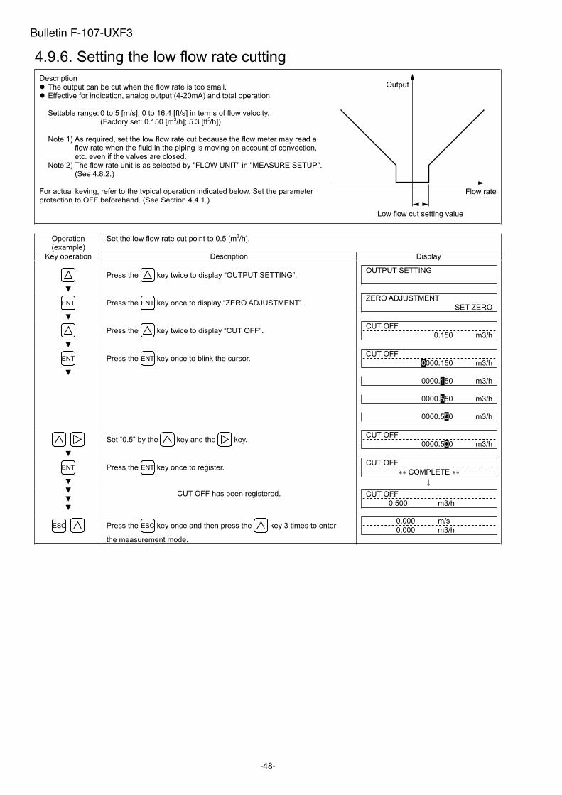
-48-
4.9.6. Setting the low flow rate cutting
Description The output can be cut when the flow rate is too small. Effective for indication, analog output (4-20mA) and total operation.
Settable range: 0 to 5 [m/s]; 0 to 16.4 [ft/s] in terms of flow velocity. (Factory set: 0.150 [m3/h]; 5.3 [ft /h])
Note 1) As required, set the low flow rate cut because the flow meter may read a flow rate when the fluid in the piping is moving on account of convection, etc. even if the valves are closed.
Note 2) The flow rate unit is as selected by "FLOW UNIT" in "MEASURE SETUP". (See 4.8.2.)
For actual keying, refer to the typical operation indicated below. Set the parameter protection to OFF beforehand. (See Section 4.4.1.)
Operation (example)
Set the low flow rate cut point to 0.5 [m3/h].
Key operation Description Display
Press the key twice to display “OUTPUT SETTING”. OUTPUT SETTING
ENT Press the ENT key once to display “ZERO ADJUSTMENT”. ZERO ADJUSTMENT
SET ZERO
Press the key twice to display “CUT OFF”. CUT OFF
0.150 m3/h
ENT Press the ENT key once to blink the cursor. CUT OFF
0000.150 m3/h
0000.150 m3/h
0000.550 m3/h
0000.550 m3/h
Set “0.5” by the key and the key. CUT OFF
0000.500 m3/h
Press the ENT key once to register. CUT OFF
COMPLETE ENT
CUT OFF has been registered. CUT OFF
0.500 m3/h
ESC Press the ESC key once and then press the key 3 times to enter
the measurement mode.
0.000 m/s
0.000 m3/h
Output
Flow rate
Low flow cut setting value
Bulletin F-107-UXF3
3
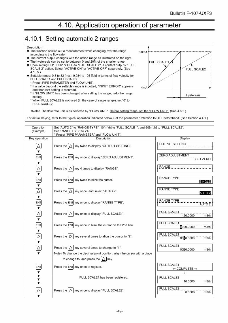
-49-
4.10. Application operation of parameter
4.10.1. Setting automatic 2 ranges
Description The function carries out a measurement while changing over the range according to the flow rate.
The current output changes with the action range as illustrated on the right. The hysteresis can be set to between 0 and 20% of the smaller range. Upon setting DO1, DO2 or DO3 to "FULL SCALE 2", a contact outputs "FULL SCALE 2" action. Select “ACTIVE ON” or “ACTIVE OFF” separately. (See 4.10.5.)
Settable range: 0.3 to 32 [m/s]; 0.984 to 105 [ft/s] in terms of flow velocity forFULL SCALE1 and FULL SCALE2. * Preset PIPE PARAMETER and FLOW UNIT.* If a value beyond the settable range is inputted, "INPUT ERROR" appears
and then last setting is resumed. * If "FLOW UNIT" has been changed after setting the range, redo the range
setting.* When FULL SCALE2 is not used (in the case of single range), set “0” to
FULL SCALE2.
<Note> The flow rate unit is as selected by "FLOW UNIT". Before setting range, set the "FLOW UNIT". (See 4.8.2.)
For actual keying, refer to the typical operation indicated below. Set the parameter protection to OFF beforehand. (See Section 4.4.1.)
Operation (example)
Set “AUTO 2” to “RANGE TYPE”, 10[m3/h] to “FULL SCALE1”, and 60[m3/h] to “FULL SCALE2”. Set “RANGE HYS.” to 7%. * Preset “PIPE PARAMETER” and “FLOW UNIT”.
Key operation Description Display
Press the key twice to display “OUTPUT SETTING”. OUTPUT SETTING
ENT Press the ENT key once to display “ZERO ADJUSTMENT”. ZERO ADJUSTMENT
SET ZERO
Press the key 4 times to display “RANGE”. RANGE
ENT Press the ENT key twice to blink the cursor. RANGE TYPE
SINGLE
Press the key once, and select “AUTO 2”. RANGE TYPE
AUTO 2
ENT Press the ENT key once to display “RANGE TYPE”. RANGE TYPE
AUTO 2
Press the key once to display “FULL SCALE1”. FULL SCALE1
20.0000 m3/h
ENT Press the ENT key once to blink the cursor on the 2nd line. FULL SCALE1
0020.0000 m3/h
Press the key several times to align the cursor to “2”. FULL SCALE1
0020.0000 m3/h
Press the key several times to change to “1”.
Note) To change the decimal point position, align the cursor with a place
to change to, and press the key.
FULL SCALE1
0010.0000 m3/h
Press the ENT key once to register. FULL SCALE1
COMPLETE ENT
FULL SCALE1 has been registered. FULL SCALE1
10.0000 m3/h
Press the key once to display “FULL SCALE2”. FULL SCALE2
0.0000 m3/h
20mA
4mA
FULL SCALE1
FULL SCALE2
Hysteresis
Bulletin F-107-UXF3
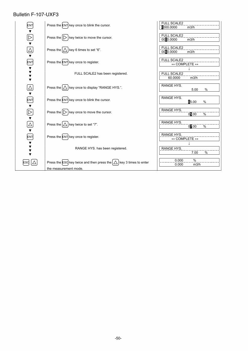
-50-
ENT Press the ENT key once to blink the cursor. FULL SCALE2
0000.0000 m3/h
Press the key twice to move the cursor. FULL SCALE2
0000.0000 m3/h
Press the key 6 times to set “6”. FULL SCALE2
0060.0000 m3/h
Press the ENT key once to register. FULL SCALE2
COMPLETE ENT
FULL SCALE2 has been registered. FULL SCALE2
60.0000 m3/h
Press the key once to display “RANGE HYS.”. RANGE HYS.
5.00 %
ENT Press the ENT key once to blink the cursor. RANGE HYS.
05.00 %
Press the key once to move the cursor. RANGE HYS.
05.00 %
Press the key twice to set “7”. RANGE HYS.
07.00 %
Press the ENT key once to register. RANGE HYS.
COMPLETE ENT
RANGE HYS. has been registered. RANGE HYS.
7.00 %
ESC Press the ESC key twice and then press the key 3 times to enter
the measurement mode.
0.000 %
0.000 m3/h
Bulletin F-107-UXF3
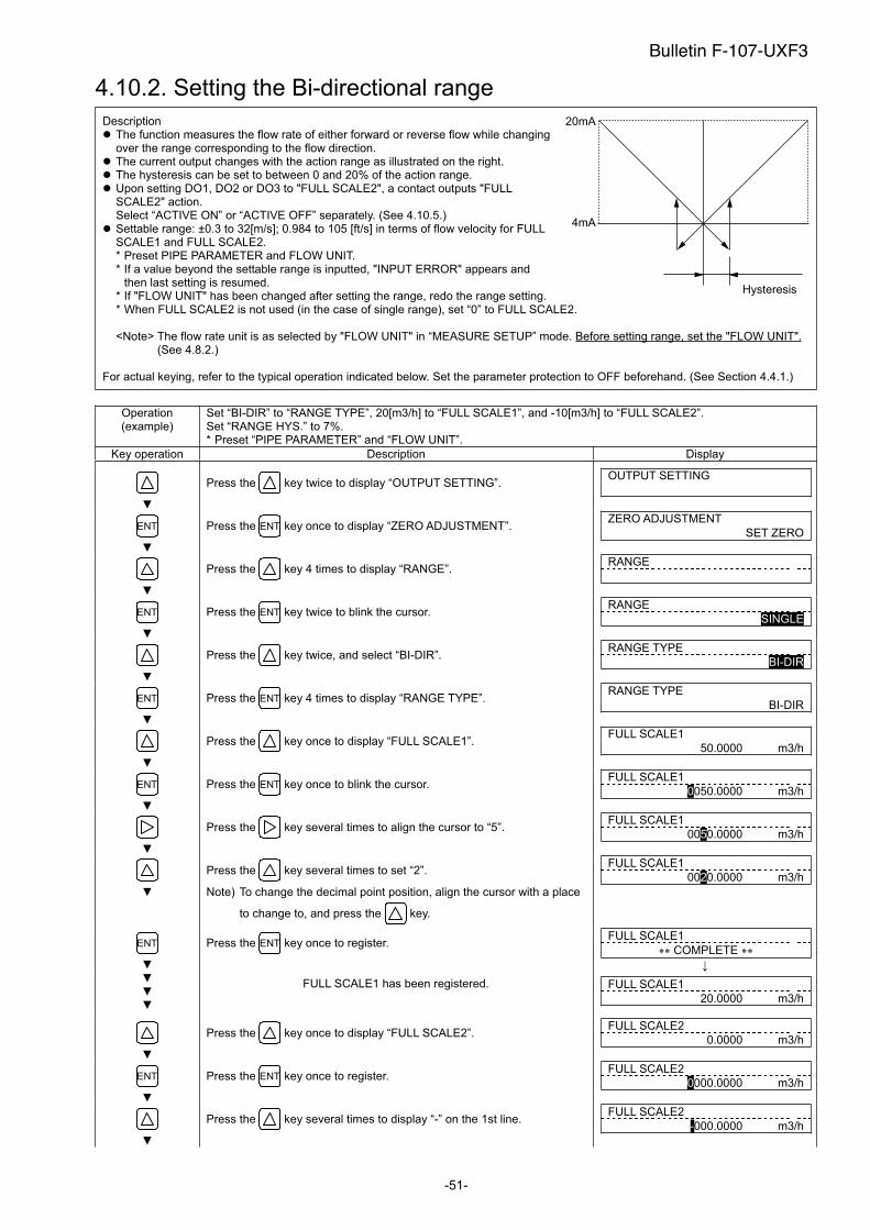
-51-
4.10.2. Setting the Bi-directional range
Description The function measures the flow rate of either forward or reverse flow while changing over the range corresponding to the flow direction.
The current output changes with the action range as illustrated on the right. The hysteresis can be set to between 0 and 20% of the action range. Upon setting DO1, DO2 or DO3 to "FULL SCALE2", a contact outputs "FULL SCALE2" action. Select “ACTIVE ON” or “ACTIVE OFF” separately. (See 4.10.5.)
Settable range: ±0.3 to 32[m/s]; 0.984 to 105 [ft/s] in terms of flow velocity for FULL SCALE1 and FULL SCALE2. * Preset PIPE PARAMETER and FLOW UNIT. * If a value beyond the settable range is inputted, "INPUT ERROR" appears and
then last setting is resumed. * If "FLOW UNIT" has been changed after setting the range, redo the range setting. * When FULL SCALE2 is not used (in the case of single range), set “0” to FULL SCALE2.
<Note> The flow rate unit is as selected by "FLOW UNIT" in “MEASURE SETUP” mode. Before setting range, set the "FLOW UNIT".(See 4.8.2.)
For actual keying, refer to the typical operation indicated below. Set the parameter protection to OFF beforehand. (See Section 4.4.1.)
Operation (example)
Set “BI-DIR” to “RANGE TYPE”, 20[m3/h] to “FULL SCALE1”, and -10[m3/h] to “FULL SCALE2”. Set “RANGE HYS.” to 7%. * Preset “PIPE PARAMETER” and “FLOW UNIT”.
Key operation Description Display
Press the key twice to display “OUTPUT SETTING”. OUTPUT SETTING
ENT Press the ENT key once to display “ZERO ADJUSTMENT”. ZERO ADJUSTMENT
SET ZERO
Press the key 4 times to display “RANGE”. RANGE
ENT Press the ENT key twice to blink the cursor. RANGE
SINGLE
Press the key twice, and select “BI-DIR”. RANGE TYPE
BI-DIR
ENT Press the ENT key 4 times to display “RANGE TYPE”. RANGE TYPE
BI-DIR
Press the key once to display “FULL SCALE1”. FULL SCALE1
50.0000 m3/h
ENT Press the ENT key once to blink the cursor. FULL SCALE1
0050.0000 m3/h
Press the key several times to align the cursor to “5”. FULL SCALE1
0050.0000 m3/h
Press the key several times to set “2”.
Note) To change the decimal point position, align the cursor with a place
to change to, and press the key.
FULL SCALE1
0020.0000 m3/h
Press the ENT key once to register. FULL SCALE1
COMPLETE ENT
FULL SCALE1 has been registered. FULL SCALE1
20.0000 m3/h
Press the key once to display “FULL SCALE2”. FULL SCALE2
0.0000 m3/h
ENT Press the ENT key once to register. FULL SCALE2
0000.0000 m3/h
Press the key several times to display “-” on the 1st line. FULL SCALE2
-000.0000 m3/h
20mA
4mA
Hysteresis
Bulletin F-107-UXF3
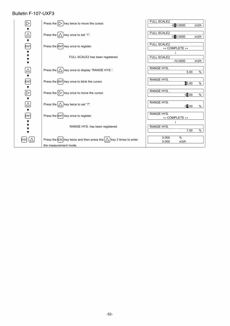
-52-
Press the key twice to move the cursor. FULL SCALE2
-000.0000 m3/h
Press the key once to set “1”. FULL SCALE2
-010.0000 m3/h
Press the ENT key once to register. FULL SCALE2
COMPLETE ENT
FULL SCALE2 has been registered. FULL SCALE2
-10.0000 m3/h
Press the key once to display “RANGE HYS.”. RANGE HYS.
5.00 %
ENT Press the ENT key once to blink the cursor. RANGE HYS.
05.00 %
Press the key once to move the cursor. RANGE HYS.
05.00 %
Press the key twice to set “7”. RANGE HYS.
07.00 %
Press the ENT key once to register. RANGE HYS.
COMPLETE ENT
RANGE HYS. has been registered. RANGE HYS.
7.00 %
ESC Press the ESC key twice and then press the key 3 times to enter
the measurement mode.
0.000 %
0.000 m3/h
Bulletin F-107-UXF3
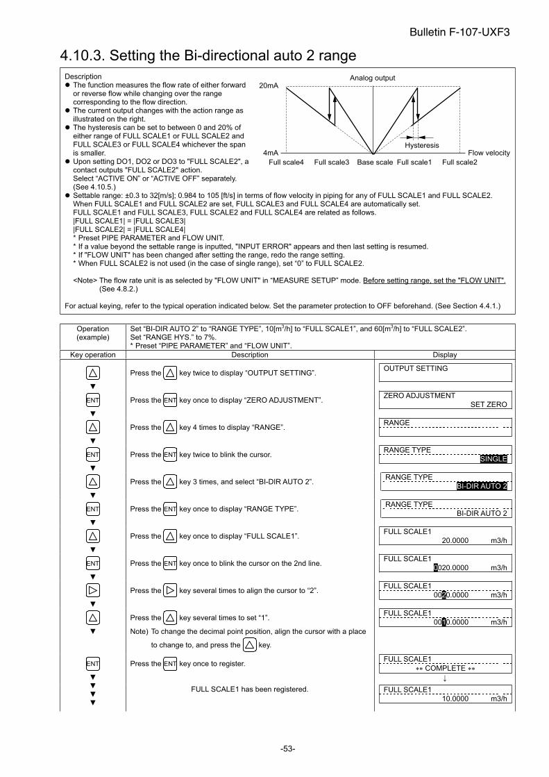
-53-
4.10.3. Setting the Bi-directional auto 2 range
Description The function measures the flow rate of either forward or reverse flow while changing over the range corresponding to the flow direction.
The current output changes with the action range as illustrated on the right.
The hysteresis can be set to between 0 and 20% of either range of FULL SCALE1 or FULL SCALE2 and FULL SCALE3 or FULL SCALE4 whichever the span is smaller.
Upon setting DO1, DO2 or DO3 to "FULL SCALE2", a contact outputs "FULL SCALE2" action. Select “ACTIVE ON” or “ACTIVE OFF” separately. (See 4.10.5.)
Settable range: ±0.3 to 32[m/s]; 0.984 to 105 [ft/s] in terms of flow velocity in piping for any of FULL SCALE1 and FULL SCALE2. When FULL SCALE1 and FULL SCALE2 are set, FULL SCALE3 and FULL SCALE4 are automatically set. FULL SCALE1 and FULL SCALE3, FULL SCALE2 and FULL SCALE4 are related as follows. |FULL SCALE1 | = |FULL SCALE3| |FULL SCALE2| = |FULL SCALE4| * Preset PIPE PARAMETER and FLOW UNIT. * If a value beyond the settable range is inputted, "INPUT ERROR" appears and then last setting is resumed. * If "FLOW UNIT" has been changed after setting the range, redo the range setting. * When FULL SCALE2 is not used (in the case of single range), set “0” to FULL SCALE2.
<Note> The flow rate unit is as selected by "FLOW UNIT" in “MEASURE SETUP” mode. Before setting range, set the "FLOW UNIT".(See 4.8.2.)
For actual keying, refer to the typical operation indicated below. Set the parameter protection to OFF beforehand. (See Section 4.4.1.)
Operation (example)
Set “BI-DIR AUTO 2” to “RANGE TYPE”, 10[m3/h] to “FULL SCALE1”, and 60[m3/h] to “FULL SCALE2”. Set “RANGE HYS.” to 7%. * Preset “PIPE PARAMETER” and “FLOW UNIT”.
Key operation Description Display
Press the key twice to display “OUTPUT SETTING”. OUTPUT SETTING
ENT Press the ENT key once to display “ZERO ADJUSTMENT”. ZERO ADJUSTMENT
SET ZERO
Press the key 4 times to display “RANGE”. RANGE
ENT Press the ENT key twice to blink the cursor. RANGE TYPE
SINGLE
Press the key 3 times, and select “BI-DIR AUTO 2”. RANGE TYPE
BI-DIR AUTO 2
ENT Press the ENT key once to display “RANGE TYPE”. RANGE TYPE
BI-DIR AUTO 2
Press the key once to display “FULL SCALE1”. FULL SCALE1
20.0000 m3/h
ENT Press the ENT key once to blink the cursor on the 2nd line. FULL SCALE1
0020.0000 m3/h
Press the key several times to align the cursor to “2”. FULL SCALE1
0020.0000 m3/h
Press the key several times to set “1”.
Note) To change the decimal point position, align the cursor with a place
to change to, and press the key.
FULL SCALE1
0010.0000 m3/h
Press the ENT key once to register. FULL SCALE1
COMPLETE ENT
FULL SCALE1 has been registered. FULL SCALE1
10.0000 m3/h
Analog output20mA
4mA Flow velocityHysteresis
Base scale Full scale1 Full scale2Full scale3Full scale4
Bulletin F-107-UXF3
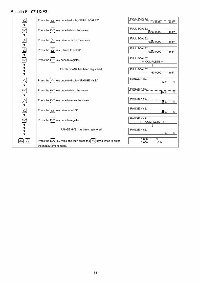
-54-
Press the key once to display “FULL SCALE2”. FULL SCALE2
0.0000 m3/h
ENT Press the ENT key once to blink the cursor. FULL SCALE2
0000.0000 m3/h
Press the key twice to move the cursor. FULL SCALE2
0000.0000 m3/h
Press the key 6 times to set “6”. FULL SCALE2
0060.0000 m3/h
Press the ENT key once to register. FULL SCALE2
COMPLETE ENT
FLOW SPAN2 has been registered. FULL SCALE2
60.0000 m3/h
Press the key once to display “RANGE HYS.”. RANGE HYS.
5.00 %
ENT Press the ENT key once to blink the cursor. RANGE HYS.
05.00 %
Press the ENT key once to move the cursor. RANGE HYS.
05.00 %
Press the key twice to set “7”. RANGE HYS.
07.00 %
Press the ENT key once to register. RANGE HYS.
COMPLETE ENT
RANGE HYS. has been registered. RANGE HYS.
7.00 %
ESC Press the ESC key twice and then press the key 3 times to enter
the measurement mode.
0.000 %
0.000 m3/h
Bulletin F-107-UXF3
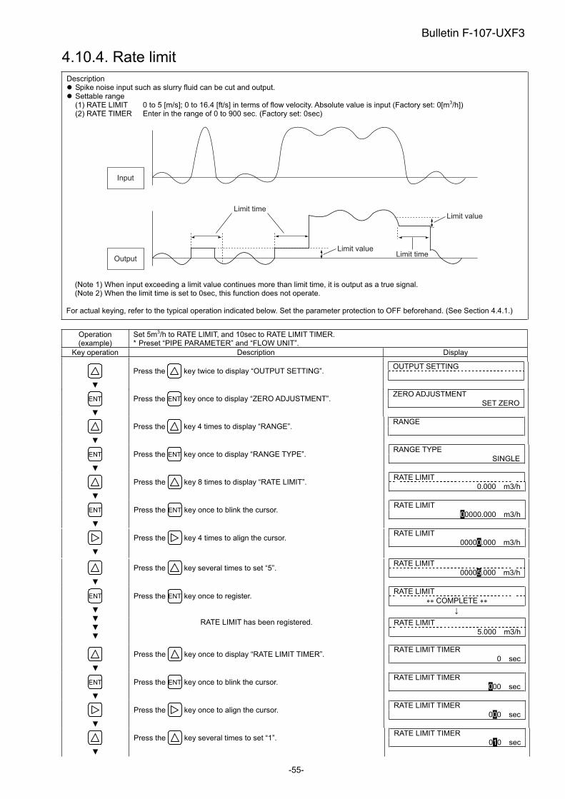
-55-
4.10.4. Rate limit
Description Spike noise input such as slurry fluid can be cut and output. Settable range (1) RATE LIMIT 0 to 5 [m/s]; 0 to 16.4 [ft/s] in terms of flow velocity. Absolute value is input (Factory set: 0[m3/h])(2) RATE TIMER Enter in the range of 0 to 900 sec. (Factory set: 0sec)
Input
Output
Limit value
Limit time
Limit time
Limit value
(Note 1) When input exceeding a limit value continues more than limit time, it is output as a true signal. (Note 2) When the limit time is set to 0sec, this function does not operate.
For actual keying, refer to the typical operation indicated below. Set the parameter protection to OFF beforehand. (See Section 4.4.1.)
Operation (example)
Set 5m3/h to RATE LIMIT, and 10sec to RATE LIMIT TIMER. * Preset “PIPE PARAMETER” and “FLOW UNIT”.
Key operation Description Display
Press the key twice to display “OUTPUT SETTING”. OUTPUT SETTING
ENT Press the ENT key once to display “ZERO ADJUSTMENT”. ZERO ADJUSTMENT
SET ZERO
Press the key 4 times to display “RANGE”. RANGE
ENT Press the ENT key once to display “RANGE TYPE”. RANGE TYPE
SINGLE
Press the key 8 times to display “RATE LIMIT”. RATE LIMIT
0.000 m3/h
ENT Press the ENT key once to blink the cursor. RATE LIMIT
00000.000 m3/h
Press the key 4 times to align the cursor. RATE LIMIT
00000.000 m3/h
Press the key several times to set “5”. RATE LIMIT
00005.000 m3/h
Press the ENT key once to register. RATE LIMIT
COMPLETE ENT
RATE LIMIT has been registered. RATE LIMIT
5.000 m3/h
Press the key once to display “RATE LIMIT TIMER”. RATE LIMIT TIMER
0 sec
ENT Press the ENT key once to blink the cursor. RATE LIMIT TIMER
000 sec
Press the key once to align the cursor. RATE LIMIT TIMER
000 sec
Press the key several times to set “1”. RATE LIMIT TIMER
010 sec
Bulletin F-107-UXF3

-56-
Press the ENT key once to register. RATE LIMIT TIMER
COMPLETE ENT
RATE LIMIT TIMER has been registered. RATE LIMIT TIMER
10 sec
ESC Press the ESC key twice and then press the key 3 times to enter
the measurement mode.
0.000 %
0.000 m3/h
Bulletin F-107-UXF3
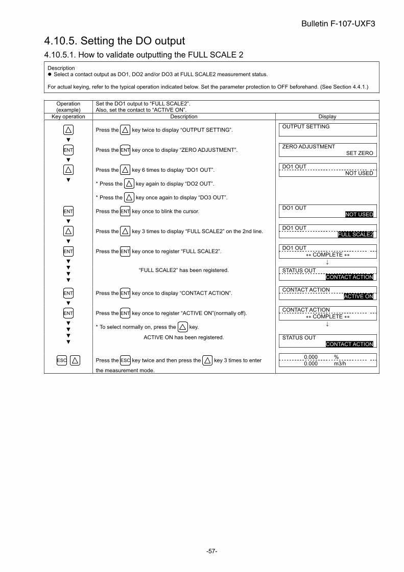
-57-
4.10.5. Setting the DO output
4.10.5.1. How to validate outputting the FULL SCALE 2
Description Select a contact output as DO1, DO2 and/or DO3 at FULL SCALE2 measurement status.
For actual keying, refer to the typical operation indicated below. Set the parameter protection to OFF beforehand. (See Section 4.4.1.)
Operation (example)
Set the DO1 output to “FULL SCALE2”. Also, set the contact to “ACTIVE ON”.
Key operation Description Display
Press the key twice to display “OUTPUT SETTING”. OUTPUT SETTING
ENT Press the ENT key once to display “ZERO ADJUSTMENT”. ZERO ADJUSTMENT
SET ZERO
Press the key 6 times to display “DO1 OUT”.
* Press the key again to display “DO2 OUT”.
* Press the key once again to display “DO3 OUT”.
DO1 OUT
NOT USED
ENT Press the ENT key once to blink the cursor. DO1 OUT
NOT USED
Press the key 3 times to display “FULL SCALE2” on the 2nd line.DO1 OUT
FULL SCALE2
Press the ENT key once to register “FULL SCALE2”. DO1 OUT
COMPLETE ENT
“FULL SCALE2” has been registered. STATUS OUT
CONTACT ACTION
ENT Press the ENT key once to display “CONTACT ACTION”. CONTACT ACTION
ACTIVE ON
Press the ENT key once to register “ACTIVE ON”(normally off).
* To select normally on, press the key.
CONTACT ACTION
COMPLETE ENT
ACTIVE ON has been registered. STATUS OUT
CONTACT ACTION
ESC Press the ESC key twice and then press the key 3 times to enter
the measurement mode.
0.000 %
0.000 m3/h
Bulletin F-107-UXF3
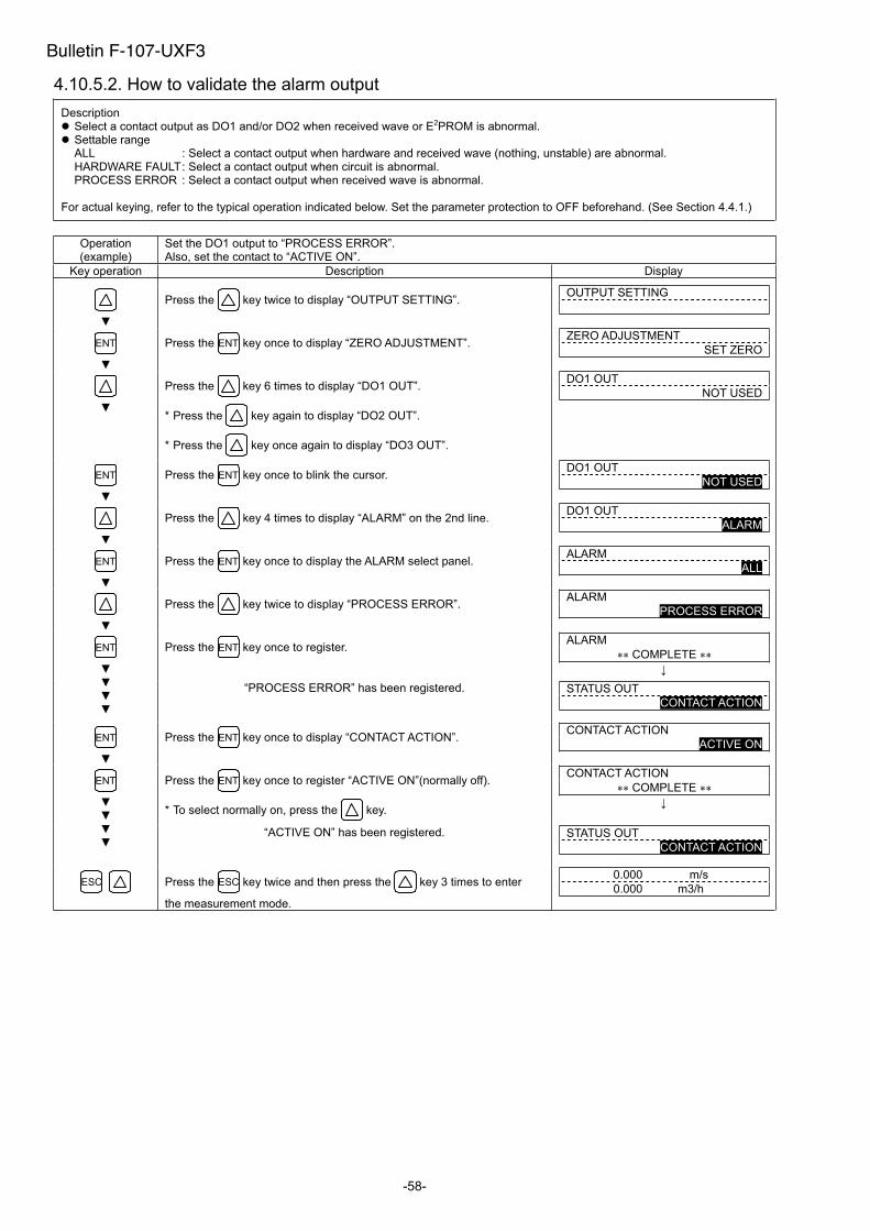
-58-
4.10.5.2. How to validate the alarm output
Description Select a contact output as DO1 and/or DO2 when received wave or E2PROM is abnormal. Settable range ALL : Select a contact output when hardware and received wave (nothing, unstable) are abnormal. HARDWARE FAULT : Select a contact output when circuit is abnormal. PROCESS ERROR : Select a contact output when received wave is abnormal.
For actual keying, refer to the typical operation indicated below. Set the parameter protection to OFF beforehand. (See Section 4.4.1.)
Operation (example)
Set the DO1 output to “PROCESS ERROR”. Also, set the contact to “ACTIVE ON”.
Key operation Description Display
Press the key twice to display “OUTPUT SETTING”. OUTPUT SETTING
ENT Press the ENT key once to display “ZERO ADJUSTMENT”. ZERO ADJUSTMENT
SET ZERO
Press the key 6 times to display “DO1 OUT”.
* Press the key again to display “DO2 OUT”.
* Press the key once again to display “DO3 OUT”.
DO1 OUT
NOT USED
ENT Press the ENT key once to blink the cursor. DO1 OUT
NOT USED
Press the key 4 times to display “ALARM” on the 2nd line. DO1 OUT
ALARM
ENT Press the ENT key once to display the ALARM select panel. ALARM
ALL
Press the key twice to display “PROCESS ERROR”. ALARM
PROCESS ERROR
Press the ENT key once to register. ALARM
COMPLETE ENT
“PROCESS ERROR” has been registered. STATUS OUT
CONTACT ACTION
ENT Press the ENT key once to display “CONTACT ACTION”. CONTACT ACTION
ACTIVE ON
Press the ENT key once to register “ACTIVE ON”(normally off).
* To select normally on, press the key.
CONTACT ACTION
COMPLETE ENT
“ACTIVE ON” has been registered. STATUS OUT
CONTACT ACTION
ESC Press the ESC key twice and then press the key 3 times to enter
the measurement mode.
0.000 m/s
0.000 m3/h
Bulletin F-107-UXF3

-59-
4.10.5.3. Setting the flow switch
Description Select a contact output as DO1, DO2 and/or DO3 when the flow rate has exceeded a setting.
Flow rate
In case of FLOW SW HIGH SWITCH
Time
Hysteresis
ON or OFF
Flow rate
In case of FLOW SW LOW SWITCH
Time
ON or OFF
Hysteresis
Settable range Flow rate : 0 to 32m/s; 0 to 105 [ft/s] in terms of flow velocity. Action : FLOW SW HIGH or FLOW SW LOW Contact action : ACTIVE ON : DO1/DO2: Normally off DO3: Normally open
ACTIVE OFF : DO1/DO2: Normally on DO3: Normally close Note) The hysteresis value set in Section 4.9.1 "Setting of flow rate range” is applied to the action range.
For actual keying, refer to the typical operation indicated below. Set the parameter protection to OFF beforehand. (See Section 4.4.1.)
Operation (example)
Set the DO1 output to “FLOW SW HIGH”, and upper limit flow rate to 12 [m3/h].Also, set the contact to “ACTIVE ON”.
Key operation Description Display
Press the key twice to display “OUTPUT SETTING”. OUTPUT SETTING
ENT Press the ENT key once to display “ZERO ADJUSTMENT”. ZERO ADJUSTMENT
SET ZERO
Press the key 6 times to display “DO1 OUT”.
* Press the key again to display “DO2 OUT”.
* Press the key once again to display “DO3 OUT”.
DO1 OUT
NOT USED
ENT Press the ENT key once to blink the cursor. DO1 OUT
NOT USED
Press the key 5 times to display “FLOW SWITCH” on the 2nd
line.
DO1 OUT
FLOW SWITCH
ENT Press the ENT key once to display the flow rate setting screen of “FLOW
SW HIGH”.
* Press the key once to display the flow rate setting screen of
“FLOW SW LOW”.
FLOW SW HIGH
10.0000 m3/h
ENT Press the ENT key once to blink the cursor. FLOW SW HIGH
0010.0000 m3/h
Press the key 3 times to move the cursor. FLOW SW HIGH
0010.0000 m3/h
Press the key twice to set “2”. FLOW SW HIGH
0012.0000 m3/h
ENT Press the ENT key once to register. FLOW SW HIGH
COMPLETE
“FLOW SW HIGH” has been registered. STATUS OUT
CONTACT ACTION
ENT Press the ENT key once to display “CONTACT ACTION”. CONTACT ACTION
ACTIVE ON
Bulletin F-107-UXF3

-60-
Press the ENT key once to register “ACTIVE ON”(normally off).
* To select normally on, press the key.
CONTACT ACTION
COMPLETE ENT
“ACTIVE ON” has been registered. STATUS OUT
CONTACT ACTION
ESC Press the ESC key twice and then press the key 3 times to enter
the measurement mode.
0.000 %
0.000 m3/h
Bulletin F-107-UXF3

-61-
4.10.5.4. How to validate the total switch
Description Select a contact output as DO1, DO2 and/or DO3 when the total value exceeds a setting. Settable range: 0.000001 to 99999999 Contact action: ACTIVE ON : DO1/DO2: Normally off DO3: Normally open ACTIVE OFF : DO1/DO2: Normally on DO3: Normally close Note) Different values can be assigned to DO1, DO2 and DO3.
For actual keying, refer to the typical operation indicated below. Set the parameter protection to OFF beforehand. (See Section 4.4.1.)
Operation (example)
Set the DO1 output to “TOTAL SWITCH”, and change the setting value from 10000[m3] to 100[m3]. Also, set the contact to “ACTIVE ON”.
Key operation Description Display
Press the key twice to display “OUTPUT SETTING”. OUTPUT SETTING
ENT Press the ENT key once to display “ZERO ADJUSTMENT”. ZERO ADJUSTMENT
SET ZERO
Press the key 6 times to display “DO1 OUT”.
* Press the key again to display “DO2 OUT”.
* Press the key once again to display “DO3 OUT”.
DO1 OUT
NOT USED
ENT Press the ENT key once to blink the cursor. DO1 OUT
NOT USED
Press the key 6 times to display “TOTAL SWITCH” on the 2nd
line.
DO1 OUT
TOTAL SWITCH
ENT Press the ENT key once to display the setting screen of “TOTAL
SWITCH”.
TOTAL SWITCH
10000 m3
ENT Press the ENT key once to blink the cursor. TOTAL SWITCH
00010000 m3
Press the key 3 times to move the cursor. TOTAL SWITCH
00010000 m3
Press the key 10 times to set “0”. TOTAL SWITCH
00000000 m3
Press the key twice to move the cursor. TOTAL SWITCH
00000000 m3
Press the key once to set “1”. TOTAL SWITCH
00000100 m3
Press the ENT key once to register. TOTAL SWITCH
COMPLETE ENT
“TOTAL SWITCH” has been registered. STATUS OUT
CONTACT ACTION
ENT Press the ENT key once to display “CONTACT ACTION”. CONTACT ACTION
ACTIVE ON
Press the ENT key once to register “ACTIVE ON”(normally off).
* To select normally on, press the key.
CONTACT ACTION
COMPLETE ENT
“ACTIVE ON” has been registered. STATUS OUT
CONTACT ACTION
ESC Press the ESC key twice and then press the key 3 times to enter
the measurement mode.
0.000 %
0.000 m3/h
Time
Setting value
Total value
ON or OFF
Bulletin F-107-UXF3
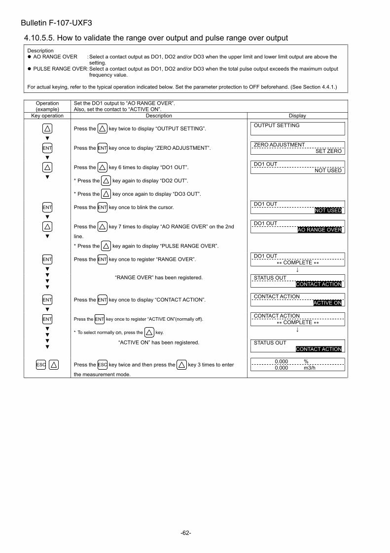
-62-
4.10.5.5. How to validate the range over output and pulse range over output
Description AO RANGE OVER : Select a contact output as DO1, DO2 and/or DO3 when the upper limit and lower limit output are above the
setting. PULSE RANGE OVER : Select a contact output as DO1, DO2 and/or DO3 when the total pulse output exceeds the maximum output
frequency value.
For actual keying, refer to the typical operation indicated below. Set the parameter protection to OFF beforehand. (See Section 4.4.1.)
Operation (example)
Set the DO1 output to “AO RANGE OVER”. Also, set the contact to “ACTIVE ON”.
Key operation Description Display
Press the key twice to display “OUTPUT SETTING”. OUTPUT SETTING
ENT Press the ENT key once to display “ZERO ADJUSTMENT”. ZERO ADJUSTMENT
SET ZERO
Press the key 6 times to display “DO1 OUT”.
* Press the key again to display “DO2 OUT”.
* Press the key once again to display “DO3 OUT”.
DO1 OUT
NOT USED
ENT Press the ENT key once to blink the cursor. DO1 OUT
NOT USED
Press the key 7 times to display “AO RANGE OVER” on the 2nd
line.
* Press the key again to display “PULSE RANGE OVER”.
DO1 OUT
AO RANGE OVER
Press the ENT key once to register “RANGE OVER”. DO1 OUT
COMPLETE ENT
“RANGE OVER” has been registered. STATUS OUT
CONTACT ACTION
ENT Press the ENT key once to display “CONTACT ACTION”. CONTACT ACTION
ACTIVE ON
Press the ENT key once to register “ACTIVE ON”(normally off).
* To select normally on, press the key.
CONTACT ACTION
COMPLETE ENT
“ACTIVE ON” has been registered. STATUS OUT
CONTACT ACTION
ESC Press the ESC key twice and then press the key 3 times to enter
the measurement mode.
0.000 %
0.000 m3/h
Bulletin F-107-UXF3
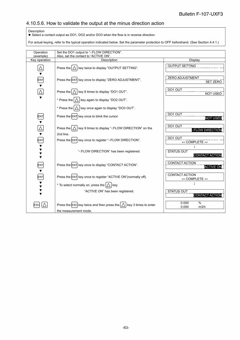
-63-
4.10.5.6. How to validate the output at the minus direction action
Description Select a contact output as DO1, DO2 and/or DO3 when the flow is in reverse direction.
For actual keying, refer to the typical operation indicated below. Set the parameter protection to OFF beforehand. (See Section 4.4.1.)
Operation (example)
Set the DO1 output to “-:FLOW DIRECTION”. Also, set the contact to “ACTIVE ON”.
Key operation Description Display
Press the key twice to display “OUTPUT SETTING”. OUTPUT SETTING
ENT Press the ENT key once to display “ZERO ADJUSTMENT”. ZERO ADJUSTMENT
SET ZERO
Press the key 6 times to display “DO1 OUT”.
* Press the key again to display “DO2 OUT”.
* Press the key once again to display “DO3 OUT”.
DO1 OUT
NOT USED
ENT Press the ENT key once to blink the cursor. DO1 OUT
NOT USED
Press the key 9 times to display “-:FLOW DIRECTION” on the
2nd line.
DO1 OUT
-:FLOW DIRECTION
Press the ENT key once to register “-:FLOW DIRECTION”. DO1 OUT
COMPLETE ENT
“-:FLOW DIRECTION” has been registered. STATUS OUT
CONTACT ACTION
ENT Press the ENT key once to display “CONTACT ACTION”. CONTACT ACTION
ACTIVE ON
Press the ENT key once to register “ACTIVE ON”(normally off).
* To select normally on, press the key.
CONTACT ACTION
COMPLETE ENT
“ACTIVE ON” has been registered. STATUS OUT
CONTACT ACTION
ESC Press the ESC key twice and then press the key 3 times to enter
the measurement mode.
0.000 %
0.000 m3/h
Bulletin F-107-UXF3
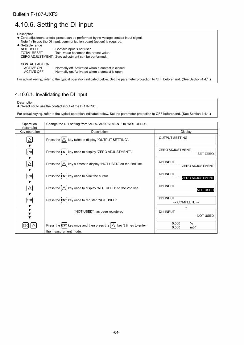
-64-
4.10.6. Setting the DI input
Description Zero adjustment or total preset can be performed by no-voltage contact input signal. Note 1) To use the DI input, communication board (option) is required.
Settable range NOT USED : Contact input is not used. TOTAL RESET : Total value becomes the preset value. ZERO ADJUSTMENT : Zero adjustment can be performed.
CONTACT ACTION ACTIVE ON : Normally off. Activated when a contact is closed. ACTIVE OFF : Normally on. Activated when a contact is open.
For actual keying, refer to the typical operation indicated below. Set the parameter protection to OFF beforehand. (See Section 4.4.1.)
4.10.6.1. Invalidating the DI input
Description Select not to use the contact input of the DI1 INPUT.
For actual keying, refer to the typical operation indicated below. Set the parameter protection to OFF beforehand. (See Section 4.4.1.)
Operation (example)
Change the DI1 setting from “ZERO ADJUSTMENT” to “NOT USED”.
Key operation Description Display
Press the key twice to display “OUTPUT SETTING”. OUTPUT SETTING
ENT Press the ENT key once to display “ZERO ADJUSTMENT”. ZERO ADJUSTMENT
SET ZERO
Press the key 9 times to display “NOT USED” on the 2nd line. DI1 INPUT
ZERO ADJUSTMENT
ENT Press the ENT key once to blink the cursor. DI1 INPUT
ZERO ADJUSTMENT
Press the key once to display “NOT USED” on the 2nd line. DI1 INPUT
NOT USED
Press the ENT key once to register “NOT USED”. DI1 INPUT
COMPLETE ENT
“NOT USED” has been registered. DI1 INPUT
NOT USED
ESC Press the ESC key once and then press the key 3 times to enter
the measurement mode.
0.000 %
0.000 m3/h
Bulletin F-107-UXF3
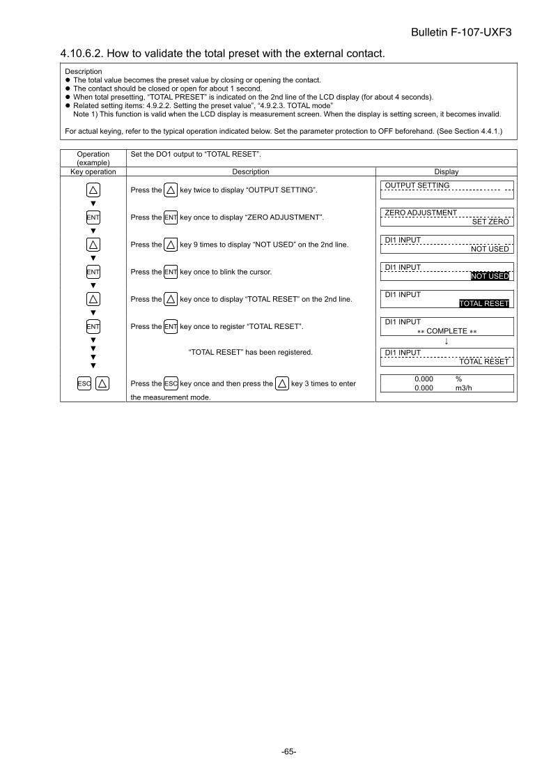
-65-
4.10.6.2. How to validate the total preset with the external contact.
Description The total value becomes the preset value by closing or opening the contact. The contact should be closed or open for about 1 second. When total presetting, “TOTAL PRESET” is indicated on the 2nd line of the LCD display (for about 4 seconds). Related setting items: 4.9.2.2. Setting the preset value”, “4.9.2.3. TOTAL mode” Note 1) This function is valid when the LCD display is measurement screen. When the display is setting screen, it becomes invalid.
For actual keying, refer to the typical operation indicated below. Set the parameter protection to OFF beforehand. (See Section 4.4.1.)
Operation (example)
Set the DO1 output to “TOTAL RESET”.
Key operation Description Display
Press the key twice to display “OUTPUT SETTING”. OUTPUT SETTING
ENT Press the ENT key once to display “ZERO ADJUSTMENT”. ZERO ADJUSTMENT
SET ZERO
Press the key 9 times to display “NOT USED” on the 2nd line. DI1 INPUT
NOT USED
ENT Press the ENT key once to blink the cursor. DI1 INPUT
NOT USED
Press the key once to display “TOTAL RESET” on the 2nd line. DI1 INPUT
TOTAL RESET
Press the ENT key once to register “TOTAL RESET”. DI1 INPUT
COMPLETE ENT
“TOTAL RESET” has been registered. DI1 INPUT
TOTAL RESET
ESC Press the ESC key once and then press the key 3 times to enter
the measurement mode.
0.000 %
0.000 m3/h
Bulletin F-107-UXF3
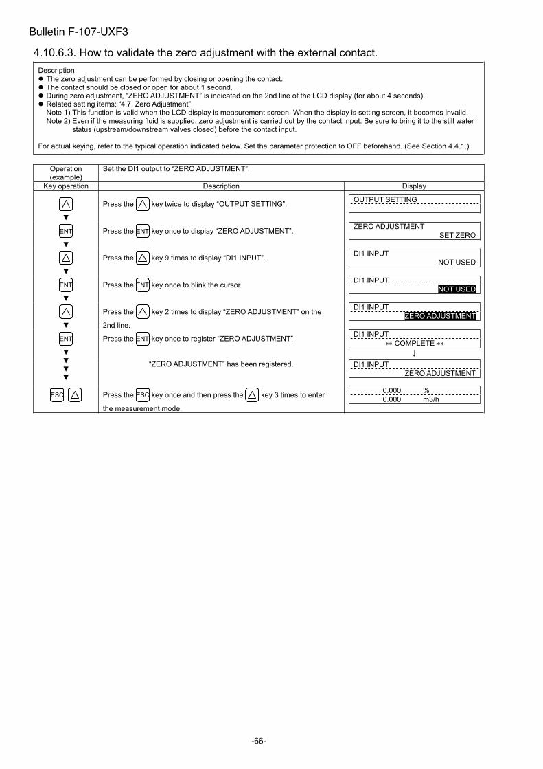
-66-
4.10.6.3. How to validate the zero adjustment with the external contact.
Description The zero adjustment can be performed by closing or opening the contact. The contact should be closed or open for about 1 second. During zero adjustment, “ZERO ADJUSTMENT” is indicated on the 2nd line of the LCD display (for about 4 seconds). Related setting items: “4.7. Zero Adjustment” Note 1) This function is valid when the LCD display is measurement screen. When the display is setting screen, it becomes invalid.Note 2) Even if the measuring fluid is supplied, zero adjustment is carried out by the contact input. Be sure to bring it to the still water
status (upstream/downstream valves closed) before the contact input.
For actual keying, refer to the typical operation indicated below. Set the parameter protection to OFF beforehand. (See Section 4.4.1.)
Operation (example)
Set the DI1 output to “ZERO ADJUSTMENT”.
Key operation Description Display
Press the key twice to display “OUTPUT SETTING”. OUTPUT SETTING
ENT Press the ENT key once to display “ZERO ADJUSTMENT”. ZERO ADJUSTMENT
SET ZERO
Press the key 9 times to display “DI1 INPUT”. DI1 INPUT
NOT USED
ENT Press the ENT key once to blink the cursor. DI1 INPUT
NOT USED
Press the key 2 times to display “ZERO ADJUSTMENT” on the
2nd line.
DI1 INPUT
ZERO ADJUSTMENT
Press the ENT key once to register “ZERO ADJUSTMENT”. DI1 INPUT
COMPLETE ENT
“ZERO ADJUSTMENT” has been registered. DI1 INPUT
ZERO ADJUSTMENT
ESC Press the ESC key once and then press the key 3 times to enter
the measurement mode.
0.000 %
0.000 m3/h
Bulletin F-107-UXF3
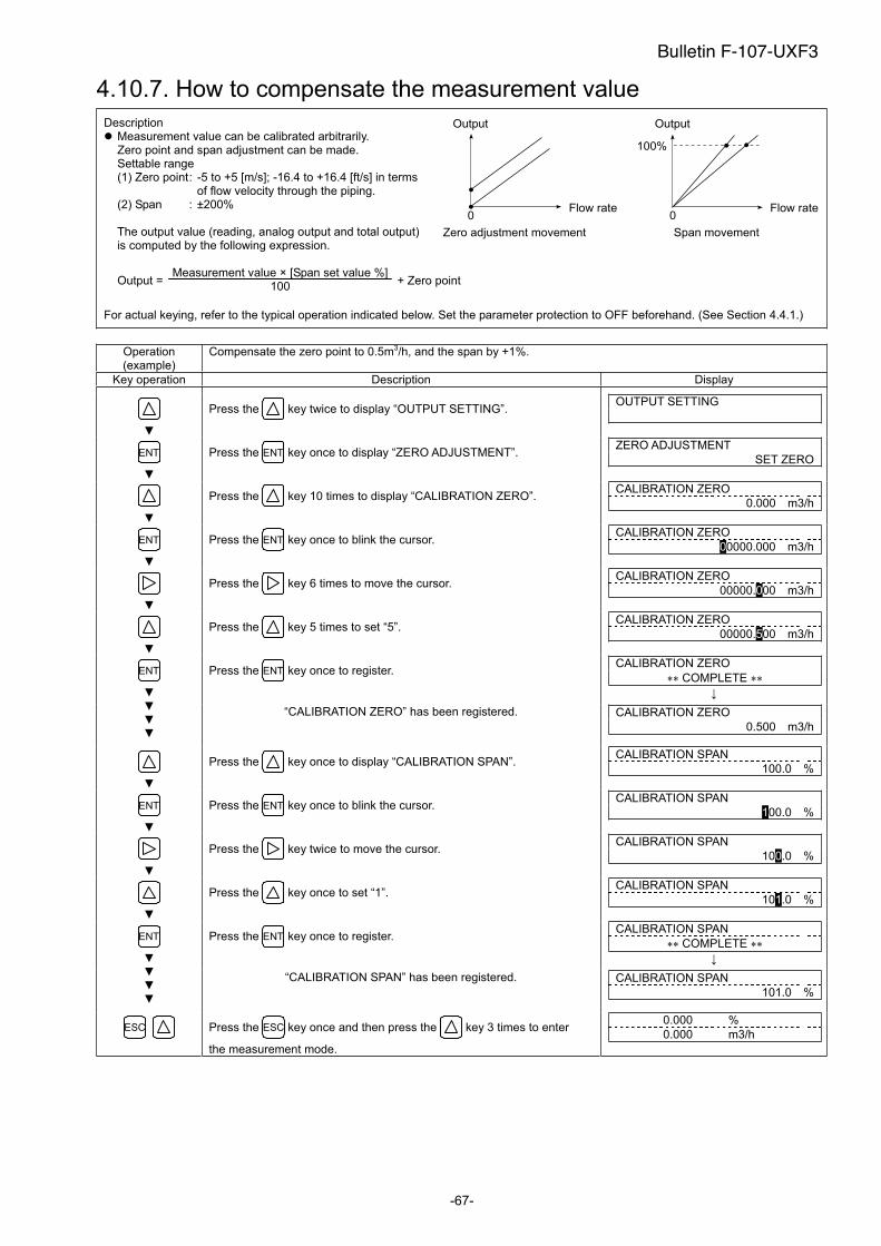
-67-
4.10.7. How to compensate the measurement value
Description Measurement value can be calibrated arbitrarily. Zero point and span adjustment can be made. Settable range (1) Zero point : -5 to +5 [m/s]; -16.4 to +16.4 [ft/s] in terms
of flow velocity through the piping.(2) Span : ±200%
The output value (reading, analog output and total output) is computed by the following expression.
Output = Measurement value × [Span set value %]
100 + Zero point
For actual keying, refer to the typical operation indicated below. Set the parameter protection to OFF beforehand. (See Section 4.4.1.)
Operation (example)
Compensate the zero point to 0.5m3/h, and the span by +1%.
Key operation Description Display
Press the key twice to display “OUTPUT SETTING”. OUTPUT SETTING
ENT Press the ENT key once to display “ZERO ADJUSTMENT”. ZERO ADJUSTMENT
SET ZERO
Press the key 10 times to display “CALIBRATION ZERO”. CALIBRATION ZERO
0.000 m3/h
ENT Press the ENT key once to blink the cursor. CALIBRATION ZERO
00000.000 m3/h
Press the key 6 times to move the cursor. CALIBRATION ZERO
00000.000 m3/h
Press the key 5 times to set “5”. CALIBRATION ZERO
00000.500 m3/h
Press the ENT key once to register. CALIBRATION ZERO
COMPLETE ENT
“CALIBRATION ZERO” has been registered. CALIBRATION ZERO
0.500 m3/h
Press the key once to display “CALIBRATION SPAN”. CALIBRATION SPAN
100.0 %
ENT Press the ENT key once to blink the cursor. CALIBRATION SPAN
100.0 %
Press the key twice to move the cursor. CALIBRATION SPAN
100.0 %
Press the key once to set “1”. CALIBRATION SPAN
101.0 %
Press the ENT key once to register. CALIBRATION SPAN
COMPLETE ENT
“CALIBRATION SPAN” has been registered. CALIBRATION SPAN
101.0 %
ESC Press the ESC key once and then press the key 3 times to enter
the measurement mode.
0.000 %
0.000 m3/h
Output
0
Zero adjustment movement
Output
0
Span movement
100%
Flow rate Flow rate
Bulletin F-107-UXF3
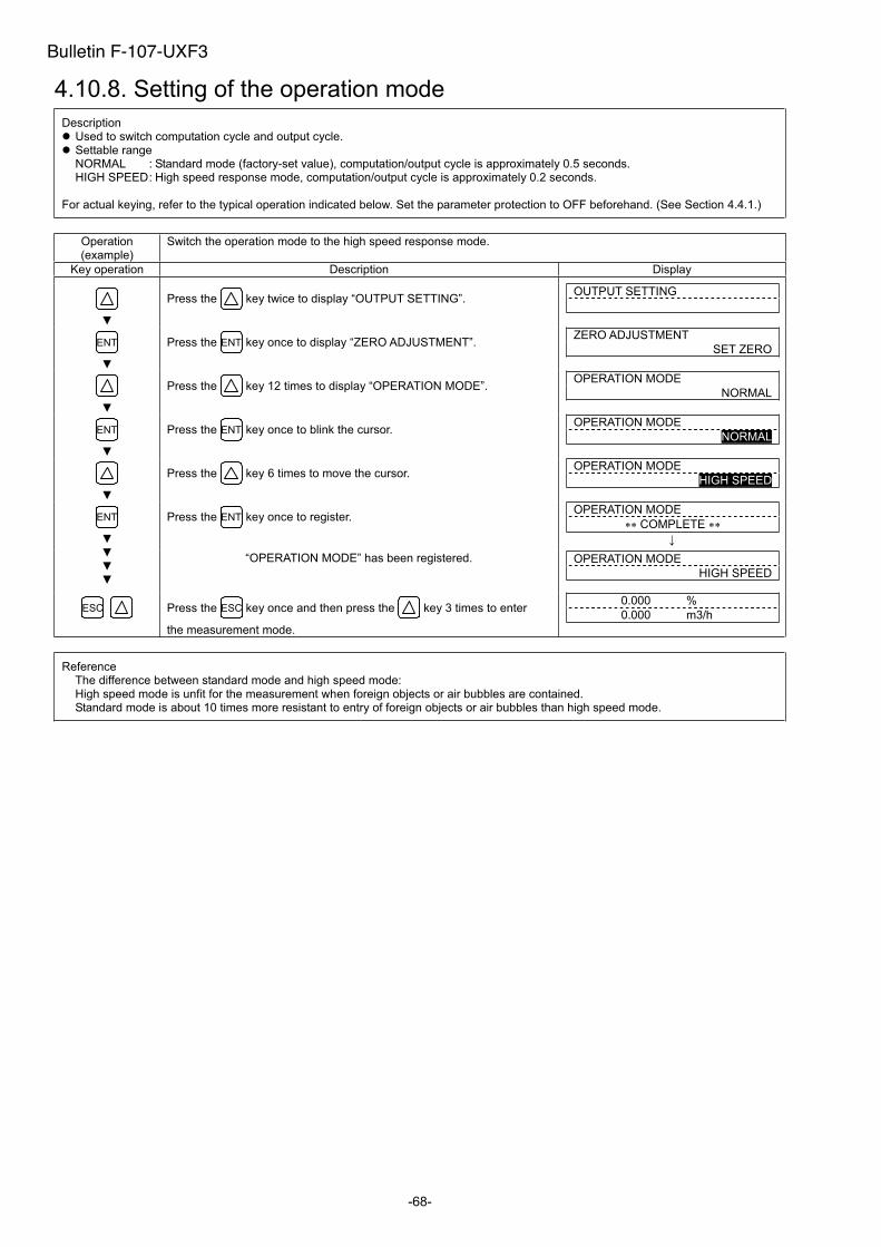
-68-
4.10.8. Setting of the operation mode
Description Used to switch computation cycle and output cycle. Settable range NORMAL : Standard mode (factory-set value), computation/output cycle is approximately 0.5 seconds. HIGH SPEED : High speed response mode, computation/output cycle is approximately 0.2 seconds.
For actual keying, refer to the typical operation indicated below. Set the parameter protection to OFF beforehand. (See Section 4.4.1.)
Operation (example)
Switch the operation mode to the high speed response mode.
Key operation Description Display
Press the key twice to display “OUTPUT SETTING”. OUTPUT SETTING
ENT Press the ENT key once to display “ZERO ADJUSTMENT”. ZERO ADJUSTMENT
SET ZERO
Press the key 12 times to display “OPERATION MODE”. OPERATION MODE
NORMAL
ENT Press the ENT key once to blink the cursor. OPERATION MODE
NORMAL
Press the key 6 times to move the cursor. OPERATION MODE
HIGH SPEED
Press the ENT key once to register. OPERATION MODE
COMPLETE ENT
“OPERATION MODE” has been registered. OPERATION MODE
HIGH SPEED
ESC Press the ESC key once and then press the key 3 times to enter
the measurement mode.
0.000 %
0.000 m3/h
ReferenceThe difference between standard mode and high speed mode:High speed mode is unfit for the measurement when foreign objects or air bubbles are contained. Standard mode is about 10 times more resistant to entry of foreign objects or air bubbles than high speed mode.
Bulletin F-107-UXF3
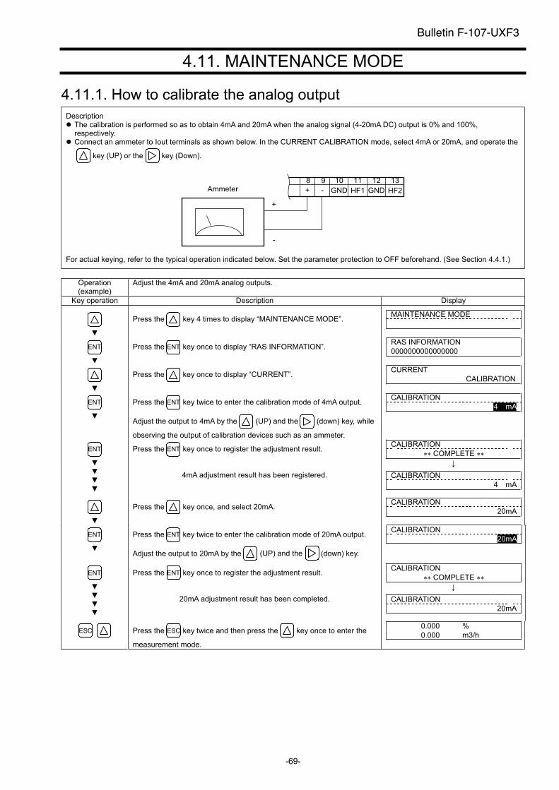
-69-
4.11. MAINTENANCE MODE
4.11.1. How to calibrate the analog output
Description The calibration is performed so as to obtain 4mA and 20mA when the analog signal (4-20mA DC) output is 0% and 100%, respectively.
Connect an ammeter to Iout terminals as shown below. In the CURRENT CALIBRATION mode, select 4mA or 20mA, and operate the
key (UP) or the key (Down).
+
-
Ammeter12 13
GND HF2
11
HF1
10
GND
98
-+
For actual keying, refer to the typical operation indicated below. Set the parameter protection to OFF beforehand. (See Section 4.4.1.)
Operation (example)
Adjust the 4mA and 20mA analog outputs.
Key operation Description Display
Press the key 4 times to display “MAINTENANCE MODE”. MAINTENANCE MODE
ENT Press the ENT key once to display “RAS INFORMATION”. RAS INFORMATION
0000000000000000
Press the key once to display “CURRENT”. CURRENT
CALIBRATION
ENT Press the ENT key twice to enter the calibration mode of 4mA output.
Adjust the output to 4mA by the (UP) and the (down) key, while
observing the output of calibration devices such as an ammeter.
CALIBRATION
4 mA
Press the ENT key once to register the adjustment result. CALIBRATION
COMPLETE ENT
4mA adjustment result has been registered. CALIBRATION
4 mA
Press the key once, and select 20mA. CALIBRATION
20mA
ENT Press the ENT key twice to enter the calibration mode of 20mA output.
Adjust the output to 20mA by the (UP) and the (down) key.
CALIBRATION
20mA
Press the ENT key once to register the adjustment result. CALIBRATION
COMPLETE ENT
20mA adjustment result has been completed. CALIBRATION
20mA
ESC Press the ESC key twice and then press the key once to enter the
measurement mode.
0.000 %
0.000 m3/h
Bulletin F-107-UXF3
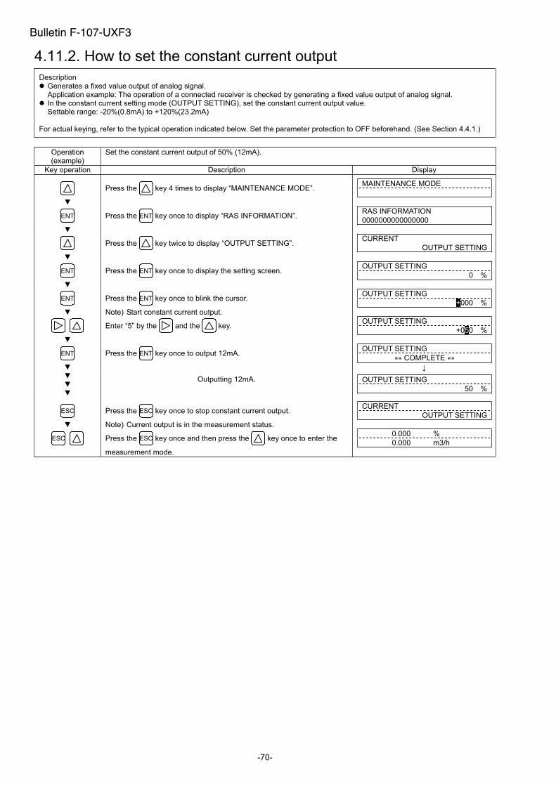
-70-
4.11.2. How to set the constant current output
Description Generates a fixed value output of analog signal. Application example: The operation of a connected receiver is checked by generating a fixed value output of analog signal. In the constant current setting mode (OUTPUT SETTING), set the constant current output value. Settable range: -20%(0.8mA) to +120%(23.2mA)
For actual keying, refer to the typical operation indicated below. Set the parameter protection to OFF beforehand. (See Section 4.4.1.)
Operation (example)
Set the constant current output of 50% (12mA).
Key operation Description Display
Press the key 4 times to display “MAINTENANCE MODE”. MAINTENANCE MODE
ENT Press the ENT key once to display “RAS INFORMATION”. RAS INFORMATION
0000000000000000
Press the key twice to display “OUTPUT SETTING”. CURRENT
OUTPUT SETTING
ENT Press the ENT key once to display the setting screen. OUTPUT SETTING
0 %
ENT Press the ENT key once to blink the cursor.
Note) Start constant current output.
OUTPUT SETTING
+000 %
Enter “5” by the and the key. OUTPUT SETTING
+050 %
Press the ENT key once to output 12mA. OUTPUT SETTING
COMPLETE ENT
Outputting 12mA. OUTPUT SETTING
50 %
ESC Press the ESC key once to stop constant current output.
Note) Current output is in the measurement status.
CURRENT
OUTPUT SETTING
ESC Press the ESC key once and then press the key once to enter the
measurement mode.
0.000 %
0.000 m3/h
Bulletin F-107-UXF3
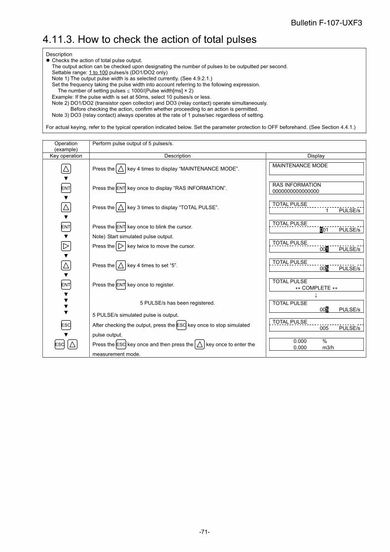
-71-
4.11.3. How to check the action of total pulses
Description Checks the action of total pulse output. The output action can be checked upon designating the number of pulses to be outputted per second. Settable range: 1 to 100 pulses/s (DO1/DO2 only) Note 1) The output pulse width is as selected currently. (See 4.9.2.1.) Set the frequency taking the pulse width into account referring to the following expression.
The number of setting pulses 1000/(Pulse width[ms] × 2)
Example: If the pulse width is set at 50ms, select 10 pulses/s or less. Note 2) DO1/DO2 (transistor open collector) and DO3 (relay contact) operate simultaneously.
Before checking the action, confirm whether proceeding to an action is permitted. Note 3) DO3 (relay contact) always operates at the rate of 1 pulse/sec regardless of setting.
For actual keying, refer to the typical operation indicated below. Set the parameter protection to OFF beforehand. (See Section 4.4.1.)
Operation (example)
Perform pulse output of 5 pulses/s.
Key operation Description Display
Press the key 4 times to display “MAINTENANCE MODE”. MAINTENANCE MODE
ENT Press the ENT key once to display “RAS INFORMATION”. RAS INFORMATION
0000000000000000
Press the key 3 times to display “TOTAL PULSE”. TOTAL PULSE
1 PULSE/s
ENT Press the ENT key once to blink the cursor.
Note) Start simulated pulse output.
TOTAL PULSE
001 PULSE/s
Press the key twice to move the cursor. TOTAL PULSE
001 PULSE/s
Press the key 4 times to set “5”. TOTAL PULSE
005 PULSE/s
Press the ENT key once to register. TOTAL PULSE
COMPLETE ENT
5 PULSE/s has been registered.
5 PULSE/s simulated pulse is output.
TOTAL PULSE
005 PULSE/s
ESC After checking the output, press the ESC key once to stop simulated
pulse output.
TOTAL PULSE
005 PULSE/s
ESC Press the ESC key once and then press the key once to enter the
measurement mode.
0.000 %
0.000 m3/h
Bulletin F-107-UXF3
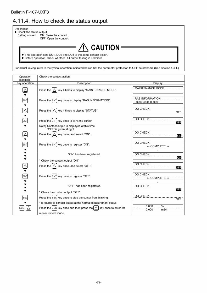
-72-
4.11.4. How to check the status output
Description Check the status output. Setting content ON: Close the contact.
OFF: Open the contact.
This operation sets DO1, DO2 and DO3 to the same contact action. Before operation, check whether DO output testing is permitted.
For actual keying, refer to the typical operation indicated below. Set the parameter protection to OFF beforehand. (See Section 4.4.1.)
Operation (example)
Check the contact action.
Key operation Description Display
Press the key 4 times to display “MAINTENANCE MODE”. MAINTENANCE MODE
ENT Press the ENT key once to display “RAS INFORMATION”. RAS INFORMATION
000000000000000
Press the key 4 times to display “STATUS”. DO CHECK
OFF
ENT Press the ENT key once to blink the cursor.
Note) Contact output is displayed at this time. “OFF” is given at right.
DO CHECK
OFF
Press the key once, and select “ON”. DO CHECK
ON
Press the ENT key once to register “ON”. DO CHECK
COMPLETE ENT
“ON” has been registered.
* Check the contact output “ON”.
DO CHECK
ON
Press the key once, and select “OFF”. DO CHECK
OFF
Press the ENT key once to register “OFF”. DO CHECK
COMPLETE ENT
“OFF” has been registered.
* Check the contact output “OFF”.
DO CHECK
OFF
ESC Press the ESC key once to stop the cursor from blinking.
* It returns to contact output at the normal measurement status.
DO CHECK
OFF
ESC Press the ESC key once and then press the key once to enter the
measurement mode.
0.000 %
0.000 m3/h
�������
Bulletin F-107-UXF3

-73-
4.11.5. How to check the DI input
Description Check the DI input. This is a function for checking the contact status on the LCD display by closing or opening the contact. Check method ON: Close the contact.
OFF: Open the contact. Note 1) To check the DI input, the communication board (option) is required.
For actual keying, refer to the typical operation indicated below. Set the parameter protection to OFF beforehand. (See Section 4.4.1.)
Operation (example)
Check the contact action.
Key operation Description Display
Press the key 4 times to display “MAINTENANCE MODE”. MAINTENANCE MODE
ENT Press the ENT key once to display “RAS INFORMATION”. RAS INFORMATION
0000000000000000
Press the key 5 times to display “DI CHECK”. DI CHECK
ENT Press the ENT key once to blink the cursor. DI CHECK
OFF
Close the contact. * Check the contact input “ON”.
DI CHECK
ON
Open the contact. * Check the contact input “OFF”.
DI CHECK
OFF
ESC Press the ESC key once to stop the cursor from blinking.
* It returns to contact output at the normal measurement status.
DI CHECK
ESC Press the ESC key once and then press the key once to enter the
measurement mode.
0.000 %s
0.000 m3/h
Bulletin F-107-UXF3
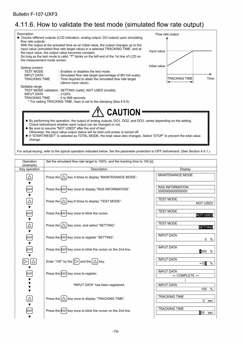
-74-
4.11.6. How to validate the test mode (simulated flow rate output)
Description Checks different outputs (LCD indication, analog output, DO output) upon simulating flow rate outputs. With the output at the actuated time as an initial value, the output changes up to the input value (simulated flow rate target value) in a selected TRACKING TIME, and at the input value, the output value becomes constant. So long as the test mode is valid, "T" blinks on the left end of the 1st line of LCD on the measurement mode screen.
Setting content TEST MODE : Enables or disables the test mode. INPUT DATA : Simulated flow rate target (percentage of MV full scale). TRACKING TIME : Time required to attain the simulated flow rate target
(above input value). Settable range
TEST MODE validation : SETTING (valid), NOT USED (invalid) INPUT DATA : ±120% TRACKING TIME : 0 to 999 seconds
* For setting TRACKING TIME, 0sec is set to the damping (See 4.9.5).
By performing the operation, the output of analog outputs, DO1, DO2, and DO3, varies depending on the setting. Check beforehand whether each output can be changed or not.
Be sure to resume "NOT USED" after the end of test. Otherwise, the input value output status will be held until power is turned off.
If “START/RESET” is selected as TOTAL MODE, the total value also changes. Select “STOP” to prevent the total value change.
For actual keying, refer to the typical operation indicated below. Set the parameter protection to OFF beforehand. (See Section 4.4.1.)
Operation (example)
Set the simulated flow rate target to 100%, and the tracking time to 100 [s].
Key operation Description Display
Press the key 4 times to display “MAINTENANCE MODE”. MAINTENANCE MODE
ENT Press the ENT key once to display “RAS INFORMATION”. RAS INFORMATION
0000000000000000
Press the key 6 times to display “TEST MODE”. TEST MODE
NOT USED
ENT Press the ENT key once to blink the cursor. TEST MODE
NOT USED
Press the key once, and select “SETTING”. TEST MODE
SETTING
ENT Press the ENT key once to register “SETTING”. INPUT DATA
0 %
ENT Press the ENT key once to blink the cursor on the 2nd line. INPUT DATA
+000 %
Enter “100” by the and the key. INPUT DATA
+100 %
Press the ENT key once to register. INPUT DATA
COMPLETE ENT
“INPUT DATA” has been registered. INPUT DATA
100 %
Press the key once to display “TRACKING TIME”. TRACKING TIME
0 sec
ENT Press the ENT key once to blink the cursor on the 2nd line. TRACKING TIME
000 sec
�������
TimeTRACKING TIME
Flow rate output
Initial value
Input value
Bulletin F-107-UXF3

-75-
Press the key once to set “100”. TRACKING TIME
100 sec
Press the ENT key once to register. TRACKING TIME
COMPLETE ENT
“TRACKING TIME” has been registered.
* Simulating flow rate output is started.
TRACKING TIME
100 s
ESC Display the measurement mode by the ESC key and the key.
"T" blinks on the left end of 1st line of LCD, and the output changes. In 100 seconds (at which tracking time is set), the output becomes stable at 10 [m3/h] (simulated flow rate target). (In case of full scale 10 [m3/h])
Note) Be sure to return the TEST MODE to "NOT USED" after checking the output.
T 0.00 %
0.000 m3/h
T 100.00 %
10.000 m3/h
Bulletin F-107-UXF3
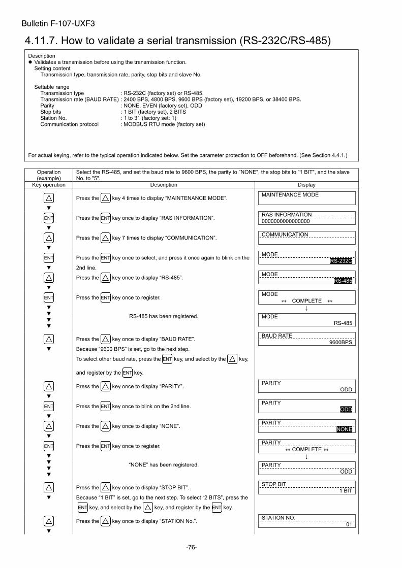
-76-
4.11.7. How to validate a serial transmission (RS-232C/RS-485)
Description Validates a transmission before using the transmission function. Setting content
Transmission type, transmission rate, parity, stop bits and slave No.
Settable range Transmission type : RS-232C (factory set) or RS-485. Transmission rate (BAUD RATE) : 2400 BPS, 4800 BPS, 9600 BPS (factory set), 19200 BPS, or 38400 BPS.Parity : NONE, EVEN (factory set), ODD Stop bits : 1 BIT (factory set), 2 BITS Station No. : 1 to 31 (factory set: 1) Communication protocol : MODBUS RTU mode (factory set)
N.
For actual keying, refer to the typical operation indicated below. Set the parameter protection to OFF beforehand. (See Section 4.4.1.)
Operation (example)
Select the RS-485, and set the baud rate to 9600 BPS, the parity to "NONE", the stop bits to "1 BIT", and the slave No. to "5".
Key operation Description Display
Press the key 4 times to display “MAINTENANCE MODE”. MAINTENANCE MODE
ENT Press the ENT key once to display “RAS INFORMATION”. RAS INFORMATION
0000000000000000
Press the key 7 times to display “COMMUNICATION”. COMMUNICATION
ENT Press the ENT key once to select, and press it once again to blink on the
2nd line.
MODE
RS-232C
Press the key once to display “RS-485”. MODE
RS-485
Press the ENT key once to register. MODE
COMPLETE ENT
RS-485 has been registered. MODE
RS-485
Press the key once to display “BAUD RATE”.
Because “9600 BPS” is set, go to the next step.
To select other baud rate, press the ENT key, and select by the key,
and register by the ENT key.
BAUD RATE
9600BPS
Press the key once to display “PARITY”. PARITY
ODD
ENT Press the ENT key once to blink on the 2nd line. PARITY
ODD
Press the key once to display “NONE”. PARITY
NONE
Press the ENT key once to register. PARITY
COMPLETE ENT
“NONE” has been registered. PARITY
ODD
Press the key once to display “STOP BIT”.
Because “1 BIT” is set, go to the next step. To select “2 BITS”, press the
ENT key, and select by the key, and register by the ENT key.
STOP BIT
1 BIT
Press the key once to display “STATION No.”. STATION NO.
01
Bulletin F-107-UXF3
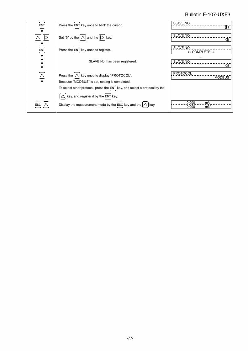
-77-
ENT Press the ENT key once to blink the cursor. SLAVE NO.
01
Set “5” by the and the key. SLAVE NO.
05
Press the ENT key once to register. SLAVE NO.
COMPLETE ENT
SLAVE No. has been registered. SLAVE NO.
05
Press the key once to display “PROTOCOL”.
Because “MODBUS” is set, setting is completed.
To select other protocol, press the ENT key, and select a protocol by the
key, and register it by the ENT key.
PROTOCOL
MODBUS
ESC Display the measurement mode by the ESC key and the key. 0.000 m/s
0.000 m3/h
Bulletin F-107-UXF3
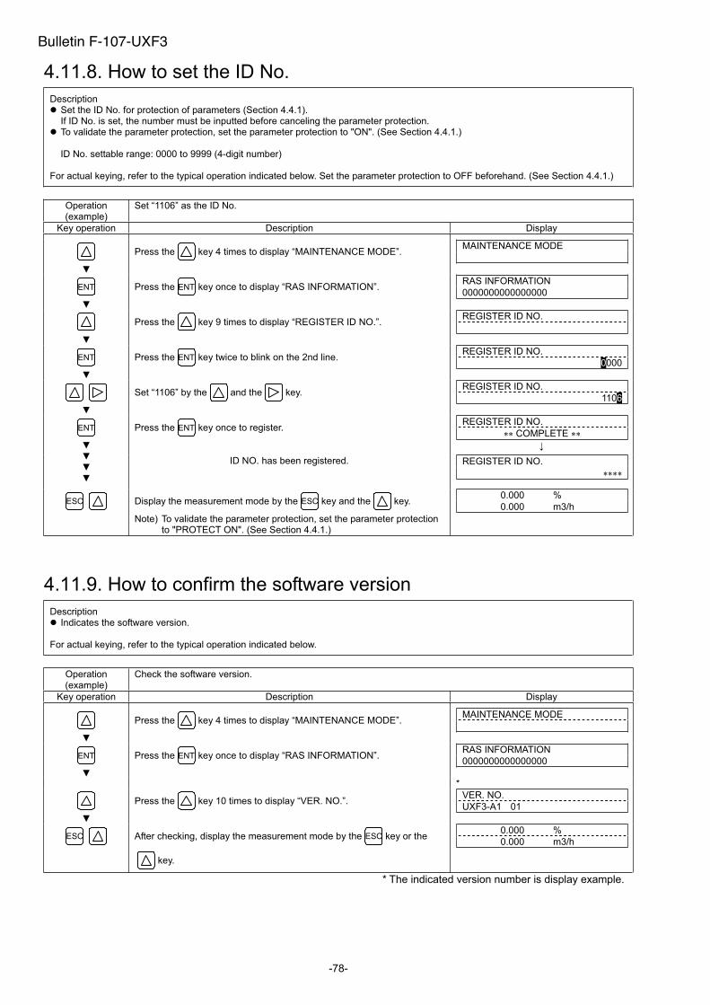
-78-
4.11.8. How to set the ID No.
Description Set the ID No. for protection of parameters (Section 4.4.1). If ID No. is set, the number must be inputted before canceling the parameter protection.
To validate the parameter protection, set the parameter protection to "ON". (See Section 4.4.1.)
ID No. settable range: 0000 to 9999 (4-digit number)
For actual keying, refer to the typical operation indicated below. Set the parameter protection to OFF beforehand. (See Section 4.4.1.)
Operation (example)
Set “1106” as the ID No.
Key operation Description Display
Press the key 4 times to display “MAINTENANCE MODE”. MAINTENANCE MODE
ENT Press the ENT key once to display “RAS INFORMATION”. RAS INFORMATION
0000000000000000
Press the key 9 times to display “REGISTER ID NO.”. REGISTER ID NO.
ENT Press the ENT key twice to blink on the 2nd line. REGISTER ID NO.
0000
Set “1106” by the and the key. REGISTER ID NO.
1106
Press the ENT key once to register. REGISTER ID NO.
COMPLETE ENT
ID NO. has been registered. REGISTER ID NO.
ESC Display the measurement mode by the ESC key and the key.
Note) To validate the parameter protection, set the parameter protection to "PROTECT ON". (See Section 4.4.1.)
0.000 %
0.000 m3/h
4.11.9. How to confirm the software version
Description Indicates the software version.
For actual keying, refer to the typical operation indicated below.
Operation (example)
Check the software version.
Key operation Description Display
Press the key 4 times to display “MAINTENANCE MODE”. MAINTENANCE MODE
Press the ENT key once to display “RAS INFORMATION”. RAS INFORMATION
0000000000000000 ENT
*
Press the key 10 times to display “VER. NO.”. VER. NO.
UXF3-A1 01
ESC After checking, display the measurement mode by the ESC key or the
key.
0.000 %
0.000 m3/h
* The indicated version number is display example.
Bulletin F-107-UXF3
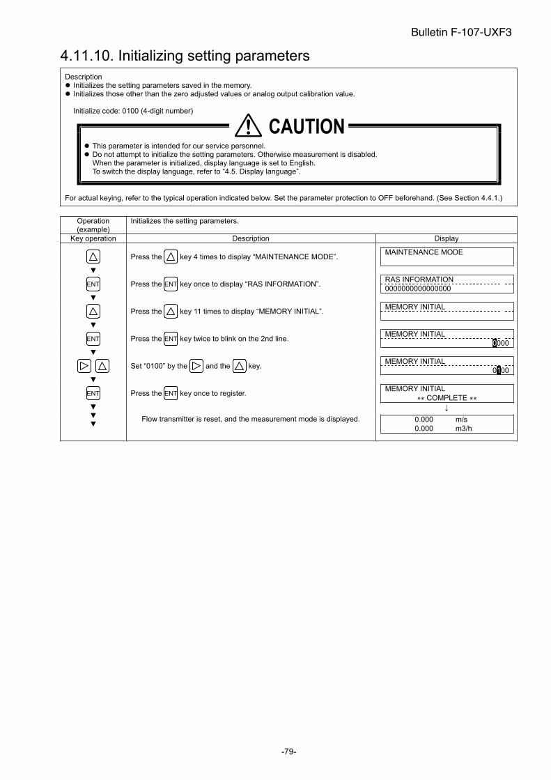
-79-
4.11.10. Initializing setting parameters
Description Initializes the setting parameters saved in the memory. Initializes those other than the zero adjusted values or analog output calibration value.
Initialize code: 0100 (4-digit number)
This parameter is intended for our service personnel. Do not attempt to initialize the setting parameters. Otherwise measurement is disabled. When the parameter is initialized, display language is set to English. To switch the display language, refer to “4.5. Display language”.
For actual keying, refer to the typical operation indicated below. Set the parameter protection to OFF beforehand. (See Section 4.4.1.)
Operation (example)
Initializes the setting parameters.
Key operation Description Display
Press the key 4 times to display “MAINTENANCE MODE”. MAINTENANCE MODE
ENT Press the ENT key once to display “RAS INFORMATION”. RAS INFORMATION
0000000000000000
Press the key 11 times to display “MEMORY INITIAL”. MEMORY INITIAL
ENT Press the ENT key twice to blink on the 2nd line. MEMORY INITIAL
0000
Set “0100” by the and the key. MEMORY INITIAL
0100
Press the ENT key once to register. MEMORY INITIAL
COMPLETE ENT
Flow transmitter is reset, and the measurement mode is displayed. 0.000 m/s
0.000 m3/h
�������
Bulletin F-107-UXF3
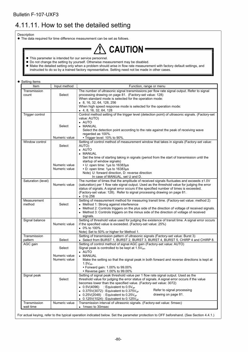
-80-
4.11.11. How to set the detailed setting
Description The data required for time difference measurement can be set as follows.
This parameter is intended for our service personnel. Do not change the setting by yourself. Otherwise measurement may be disabled. Make the detailed setting only when a problem should arise in flow rate measurement with factory default settings, and instructed to do so by a trained factory representative. Setting need not be made in other cases.
Setting items
Item Input method Function, range or menu
Transmission count Select
The number of ultrasonic signal transmissions per flow rate signal output. Refer to signalprocessing drawing on page 81. (Factory-set value: 128) When standard mode is selected for the operation mode:
8, 16, 32, 64, 128, 256 When high speed response mode is selected for the operation mode:
4, 8, 16, 32, 64, 128
Trigger control
Select
Numeric value
Control method setting of the trigger level (detection point) of ultrasonic signals. (Factory-set value: AUTO)
AUTO
MANUAL Select the detection point according to the rate against the peak of receiving wave regarded as 100%. Trigger level: 10% to 90%.
Window control Select
Numeric valueNumeric value
Setting of control method of measurement window that takes in signals (Factory-set value: AUTO)
AUTO
MANUAL Set the time of starting taking in signals (period from the start of transmission until the startup of window signals) U: open time: 1µs to 16383µs D: open time: 1µs to 16383µs
Note) U: forward direction, D: reverse direction In case of MANUAL, set U and D.
Saturation (level) Numeric value
The number of times that the amplitude of received signals fluctuates and exceeds ±1.0V (saturation) per 1 flow rate signal output. Used as the threshold value for judging the error status of signals. A signal error occurs if the specified number of times is exceeded. (Factory-set value: 128). Refer to signal processing drawing on page 81.
0 to 256
Measurementmethod Select
Setting of measurement method for measuring transit time. (Factory-set value: method 2)
Method 1: Strong against interference
Method 2: Controls triggers on the plus side of the direction of voltage of received signals.
Method 3: Controls triggers on the minus side of the direction of voltage of received signals.
Signal balance Numeric value
Setting of threshold value used for judging the existence of transit time. A signal error occurs if the specified value is exceeded. (Factory-set value: 25%)
0% to 100% Note) Set to 50% or higher for Method 1.
Transmission pattern Select
Setting of transmission pattern of ultrasonic signals (Factory-set value: Burst 3)
Select from BURST 1, BURST 2, BURST 3, BURST 4, BURST 5, CHIRP 4 and CHIRP 8.
AGC gain Select
Numeric valueNumeric value
Setting of control method of signal AGC gain (Factory-set value: AUTO) Signal peak is controlled to be kept at 1.5VPP.
AUTO
MANUAL Make the setting so that the signal peak in both forward and reverse directions is kept at 1.5VPP. Forward gain: 1.00% to 99.00% Reverse gain: 1.00% to 99.00%
Signal peak Select
Setting of signal peak threshold value per 1 flow rate signal output. Used as the threshold value for judging the error status of signals. A signal error occurs if the value becomes lower than the specified value. (Factory-set value: 3072)
0.5V(4096) : Equivalent to 0.5V0P
0.375V(3072) : Equivalent to 0.375V0P
0.25V(2048) : Equivalent to 0.25V0P
0.125V(1024) : Equivalent to 0.125V0P
Transmission wait time
Numeric value Transmission interval of ultrasonic signals. (Factory-set value: 5msec)
1msec to 30msec
For actual keying, refer to the typical operation indicated below. Set the parameter protection to OFF beforehand. (See Section 4.4.1.)
�������
Bulletin F-107-UXF3
Refer to signal processing
drawing on page 81.
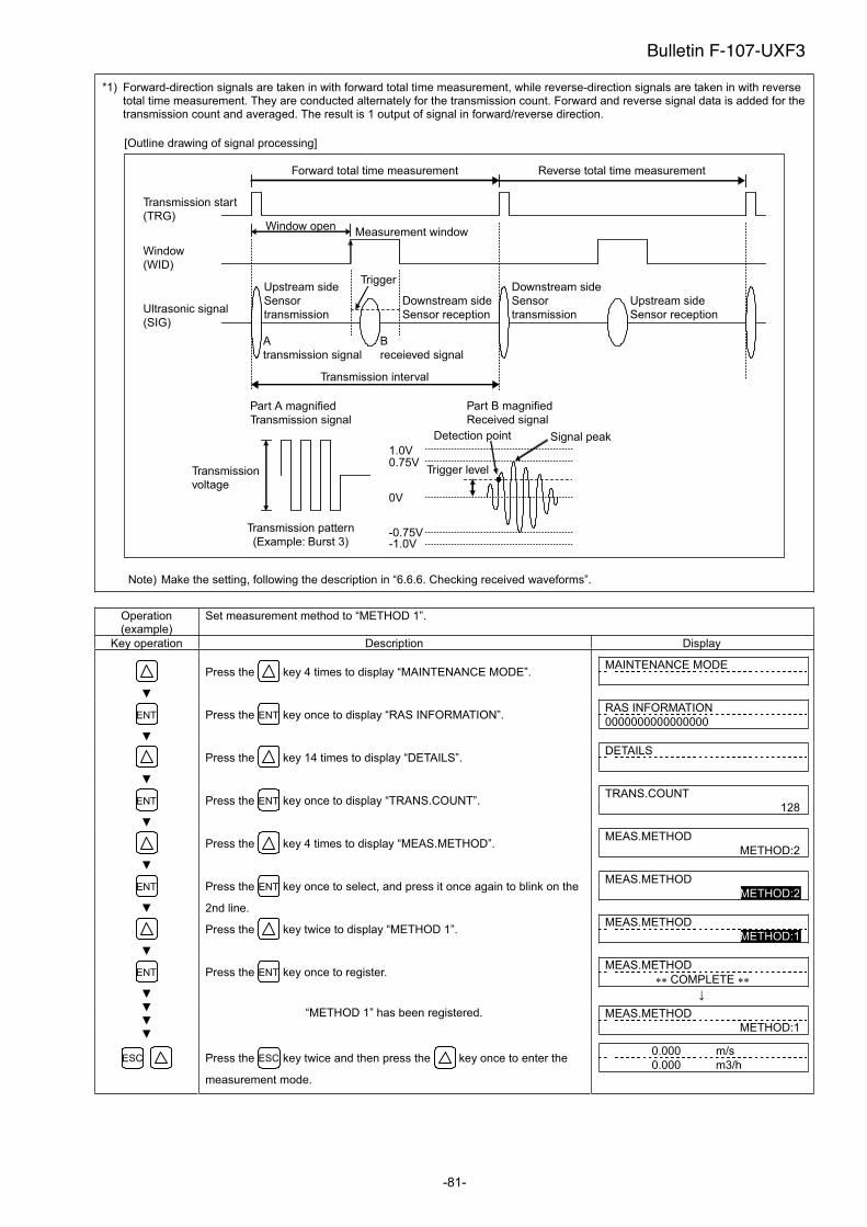
-81-
*1) Forward-direction signals are taken in with forward total time measurement, while reverse-direction signals are taken in with reverse total time measurement. They are conducted alternately for the transmission count. Forward and reverse signal data is added for the transmission count and averaged. The result is 1 output of signal in forward/reverse direction.
Window
(WID)
Ultrasonic signal
(SIG)
Transmission start
(TRG)
A
transmission signal
B
receieved signal
Measurement windowWindow open
Trigger
Part B magnified
Received signal
Part A magnified
Transmission signal
[Outline drawing of signal processing]
Transmission
voltage
Transmission pattern
(Example: Burst 3)
Trigger level
0V
0.75V1.0V
-0.75V-1.0V
Detection point
Forward total time measurement Reverse total time measurement
Signal peak
Upstream side
Sensor
transmission
Downstream side
Sensor reception
Upstream side
Sensor reception
Downstream side
Sensor
transmission
Transmission interval
Note) Make the setting, following the description in “6.6.6. Checking received waveforms”.
Operation (example)
Set measurement method to “METHOD 1”.
Key operation Description Display
Press the key 4 times to display “MAINTENANCE MODE”. MAINTENANCE MODE
ENT Press the ENT key once to display “RAS INFORMATION”. RAS INFORMATION
0000000000000000
Press the key 14 times to display “DETAILS”. DETAILS
ENT Press the ENT key once to display “TRANS.COUNT”. TRANS.COUNT
128
Press the key 4 times to display “MEAS.METHOD”. MEAS.METHOD
METHOD:2
ENT Press the ENT key once to select, and press it once again to blink on the
2nd line.
MEAS.METHOD
METHOD:2
Press the key twice to display “METHOD 1”. MEAS.METHOD
METHOD:1
Press the ENT key once to register. MEAS.METHOD
COMPLETE ENT
“METHOD 1” has been registered. MEAS.METHOD
METHOD:1
ESC Press the ESC key twice and then press the key once to enter the
measurement mode.
0.000 m/s
0.000 m3/h
Bulletin F-107-UXF3
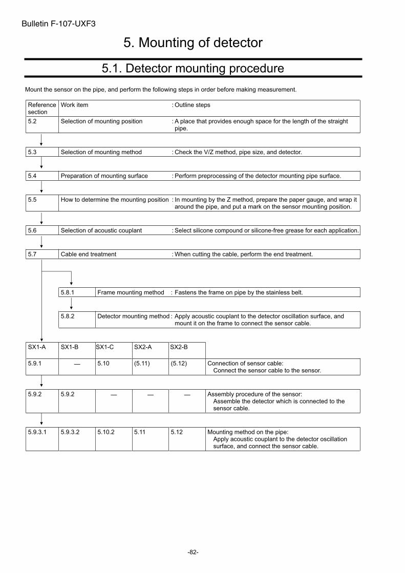
-82-
5. Mounting of detector
5.1. Detector mounting procedure
Mount the sensor on the pipe, and perform the following steps in order before making measurement.
Reference section
Work item : Outline steps
5.2 Selection of mounting position : A place that provides enough space for the length of the straight pipe.
5.3 Selection of mounting method : Check the V/Z method, pipe size, and detector.
5.4 Preparation of mounting surface : Perform preprocessing of the detector mounting pipe surface.
5.5 How to determine the mounting position : In mounting by the Z method, prepare the paper gauge, and wrap it around the pipe, and put a mark on the sensor mounting position.
5.6 Selection of acoustic couplant : Select silicone compound or silicone-free grease for each application.
5.7 Cable end treatment : When cutting the cable, perform the end treatment.
5.8.1 Frame mounting method : Fastens the frame on pipe by the stainless belt.
5.8.2 Detector mounting method : Apply acoustic couplant to the detector oscillation surface, and mount it on the frame to connect the sensor cable.
SX1-A.
SX1-B SX1-C.
SX2-A SX2-B
5.9.1 5.10 (5.11) (5.12) Connection of sensor cable: Connect the sensor cable to the sensor.
5.9.2 5.9.2 Assembly procedure of the sensor: Assemble the detector which is connected to the sensor cable.
5.9.3.1 5.9.3.2 5.10.2 5.11 5.12 Mounting method on the pipe: Apply acoustic couplant to the detector oscillation surface, and connect the sensor cable.
Bulletin F-107-UXF3
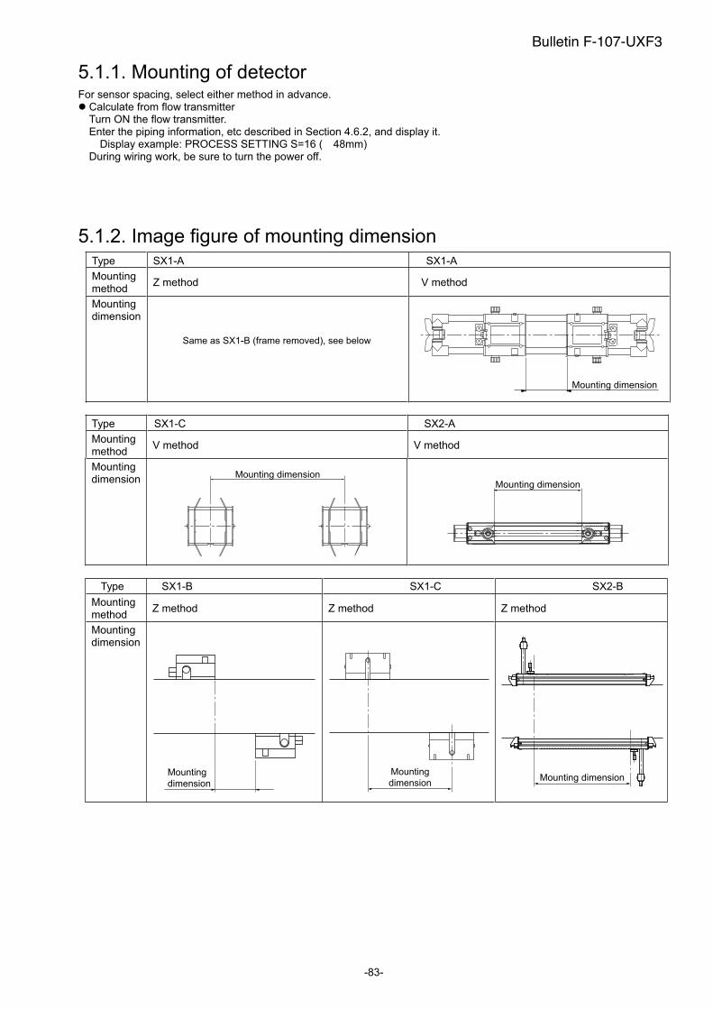
-83-
5.1.1. Mounting of detector For sensor spacing, select either method in advance.
Calculate from flow transmitter Turn ON the flow transmitter. Enter the piping information, etc described in Section 4.6.2, and display it. Display example: PROCESS SETTING S=16 ( 48mm) During wiring work, be sure to turn the power off.
5.1.2. Image figure of mounting dimension Type SX1-A SX1-A
Mounting method
Z method V method
Mounting dimension
Same as SX1-B (frame removed), see below
Mounting dimension
Type SX1-C SX2-A
Mounting method
V method V method
Mounting dimension
Mounting dimensionMounting dimension
Type SX1-B SX1-C SX2-B
Mounting method
Z method Z method Z method
Mounting dimension
Mounting
dimension
Mounting
dimensionMounting dimension
Bulletin F-107-UXF3
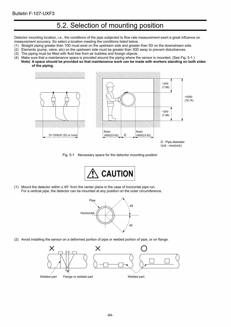
-84-
5.2. Selection of mounting position
Detector mounting location, i.e., the conditions of the pipe subjected to flow rate measurement exert a great influence on measurement accuracy. So select a location meeting the conditions listed below. (1) Straight piping greater than 10D must exist on the upstream side and greater than 5D on the downstream side. (2) Elements (pump, valve, etc) on the upstream side must be greater than 30D away to prevent disturbances. (3) The piping must be filled with fluid free from air bubbles and foreign objects. (4) Make sure that a maintenance space is provided around the piping where the sensor is mounted. (See Fig. 5-1.)
Note) A space should be provided so that maintenance work can be made with workers standing on both sides of the piping.
D+1200(47.25) or more DNote)
>600(23.62)
Note)
>600(23.62)
D : Pipe diameter
Unit : mm(inch)
Fig. 5-1 Necessary space for the detector mounting position
�������
(1) Mount the detector within ± 45 from the center plane in the case of horizontal pipe run. For a vertical pipe, the detector can be mounted at any position on the outer circumference.
Horizontal
Pipe
45
45
(2) Avoid installing the sensor on a deformed portion of pipe or welded portion of pipe, or on flange.
Welded part Flange or welded part Welded part
Bulletin F-107-UXF3
>200
(7.88)
>200
(7.88)
>2000
(78.74)
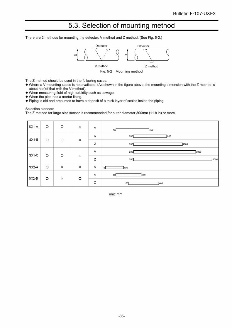
-85-
5.3. Selection of mounting method
There are 2 methods for mounting the detector; V method and Z method. (See Fig. 5-2.)
Detector
D
V method
Detector
D
Z method
Fig. 5-2 Mounting method
The Z method should be used in the following cases. Where a V mounting space is not available. (As shown in the figure above, the mounting dimension with the Z method is about half of that with the V method). When measuring fluid of high turbidity such as sewage. When the pipe has a mortar lining. Piping is old and presumed to have a deposit of a thick layer of scales inside the piping.
Selection standard The Z method for large size sensor is recommended for outer diameter 300mm (11.8 in) or more.
Bulletin F-107-UXF3
unit: mm
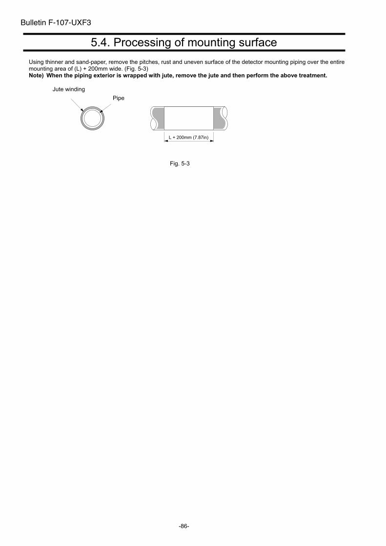
-86-
5.4. Processing of mounting surface
Using thinner and sand-paper, remove the pitches, rust and uneven surface of the detector mounting piping over the entire mounting area of (L) + 200mm wide. (Fig. 5-3) Note) When the piping exterior is wrapped with jute, remove the jute and then perform the above treatment.
Jute winding
Pipe
Fig. 5-3
Bulletin F-107-UXF3
L + 200mm (7.87in)
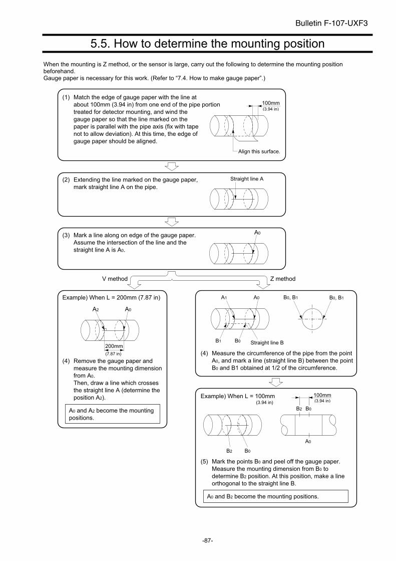
-87-
5.5. How to determine the mounting position
When the mounting is Z method, or the sensor is large, carry out the following to determine the mounting position beforehand. Gauge paper is necessary for this work. (Refer to “7.4. How to make gauge paper”.)
Align this surface.
100mm
Straight line A
A0
A0A2
200mm
A0A1
B1 B0 Straight line B
B0, B1B0, B1
B0B2
B2 B0
A0
100mm
Match the edge of gauge paper with the line at
about 100mm (3.94 in) from one end of the pipe portion
treated for detector mounting, and wind the
gauge paper so that the line marked on the
paper is parallel with the pipe axis (fix with tape
not to allow deviation). At this time, the edge of
gauge paper should be aligned.
(1)
Extending the line marked on the gauge paper,
mark straight line A on the pipe.
(2)
Mark a line along on edge of the gauge paper.
Assume the intersection of the line and the
straight line A is A0.
(3)
V method Z method
Remove the gauge paper and
measure the mounting dimension
from A0.
Then, draw a line which crosses
the straight line A (determine the
position A2).
(4)
Measure the circumference of the pipe from the point
A0, and mark a line (straight line B) between the point
B0 and B1 obtained at 1/2 of the circumference.
(4)
Example) When L = 100mm
Mark the points B0 and peel off the gauge paper.
Measure the mounting dimension from B0 to
determine B2 position. At this position, make a line
orthogonal to the straight line B.
(5)
A0 and A2 become the mounting
positions.
A0 and B2 become the mounting positions.
Example) When L = 200mm (7.87 in)
Bulletin F-107-UXF3
(3.94 in)
(7.87 in)
(3.94 in)(3.94 in)
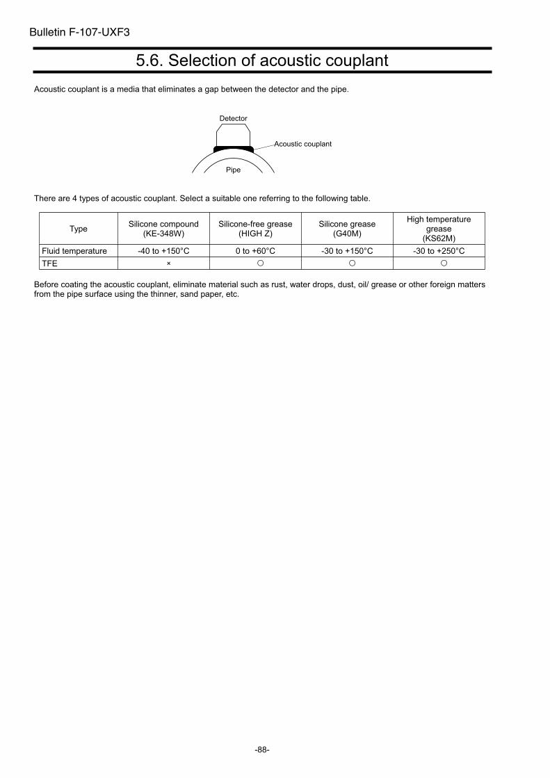
-88-
5.6. Selection of acoustic couplant
Acoustic couplant is a media that eliminates a gap between the detector and the pipe.
Acoustic couplant
Pipe
Detector
There are 4 types of acoustic couplant. Select a suitable one referring to the following table.
Type Silicone compound
(KE-348W) Silicone-free grease
(HIGH Z) Silicone grease
(G40M)
High temperature grease
(KS62M)
Fluid temperature -40 to +150°C 0 to +60°C -30 to +150°C -30 to +250°C
TFE ×
Before coating the acoustic couplant, eliminate material such as rust, water drops, dust, oil/ grease or other foreign matters from the pipe surface using the thinner, sand paper, etc.
Bulletin F-107-UXF3
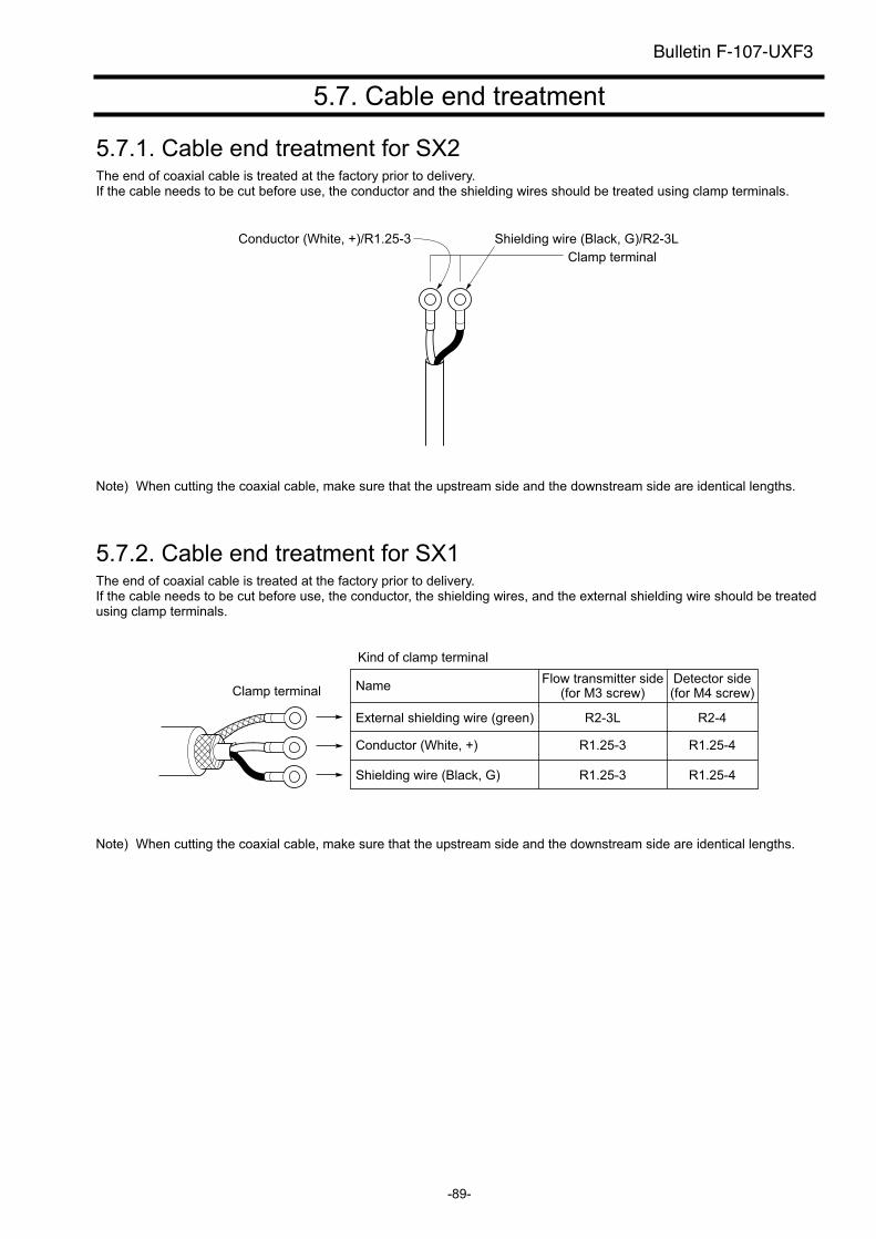
-89-
5.7. Cable end treatment
5.7.1. Cable end treatment for SX2The end of coaxial cable is treated at the factory prior to delivery. If the cable needs to be cut before use, the conductor and the shielding wires should be treated using clamp terminals.
Clamp terminal
Shielding wire (Black, G)/R2-3LConductor (White, +)/R1.25-3
Note) When cutting the coaxial cable, make sure that the upstream side and the downstream side are identical lengths.
5.7.2. Cable end treatment for SX1The end of coaxial cable is treated at the factory prior to delivery. If the cable needs to be cut before use, the conductor, the shielding wires, and the external shielding wire should be treated using clamp terminals.
Kind of clamp terminal
Clamp terminal NameFlow transmitter side
(for M3 screw)Detector side(for M4 screw)
External shielding wire (green) R2-3L R2-4
Conductor (White, +) R1.25-3 R1.25-4
Shielding wire (Black, G) R1.25-3 R1.25-4
Note) When cutting the coaxial cable, make sure that the upstream side and the downstream side are identical lengths.
Bulletin F-107-UXF3

- 90 -
Bulletin F-107-UXF3
(Page intentionally blank)
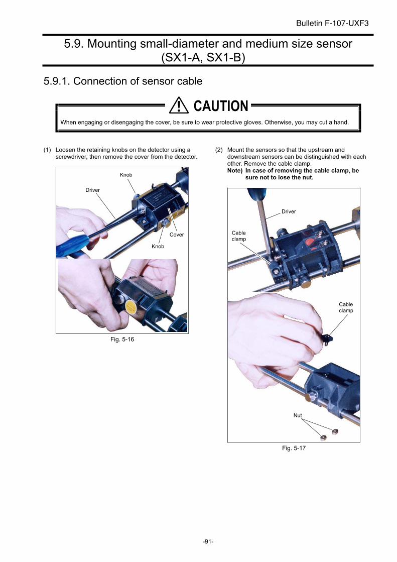
-91-
5.9. Mounting small-diameter and medium size sensor (SX1-A, SX1-B)
5.9.1. Connection of sensor cable
When engaging or disengaging the cover, be sure to wear protective gloves. Otherwise, you may cut a hand.
(1) Loosen the retaining knobs on the detector using a screwdriver, then remove the cover from the detector.
Fig. 5-16
(2) Mount the sensors so that the upstream and downstream sensors can be distinguished with each other. Remove the cable clamp. Note) In case of removing the cable clamp, be
sure not to lose the nut.
Fig. 5-17
�������
Driver
Knob
Cover
Knob
Driver
Cableclamp
Cableclamp
Nut
Bulletin F-107-UXF3
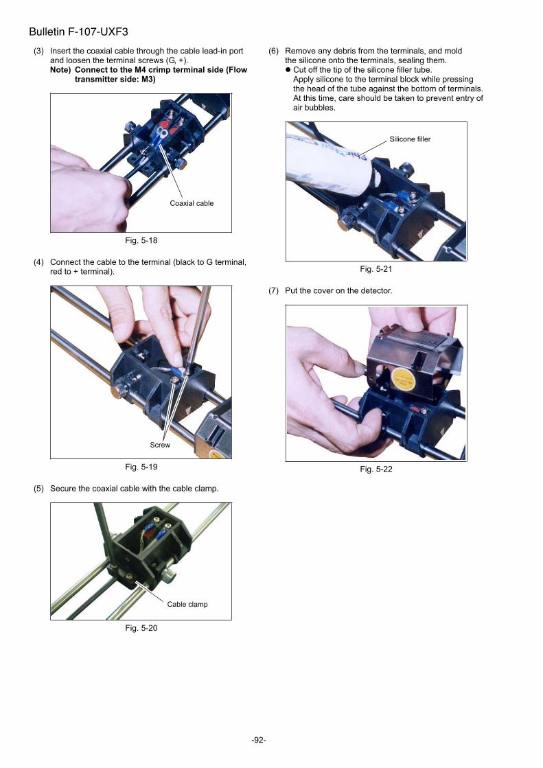
-92-
(3) Insert the coaxial cable through the cable lead-in port and loosen the terminal screws (G, +). Note) Connect to the M4 crimp terminal side (Flow
transmitter side: M3)
Fig. 5-18
(4) Connect the cable to the terminal (black to G terminal, red to + terminal).
Fig. 5-19
(5) Secure the coaxial cable with the cable clamp.
Fig. 5-20
(6) Remove any debris from the terminals, and mold the silicone onto the terminals, sealing them.
Cut off the tip of the silicone filler tube. Apply silicone to the terminal block while pressing the head of the tube against the bottom of terminals. At this time, care should be taken to prevent entry of air bubbles.
Fig. 5-21
(7) Put the cover on the detector.
Fig. 5-22
Screw
Coaxial cable
Cable clamp
Silicone filler
Bulletin F-107-UXF3
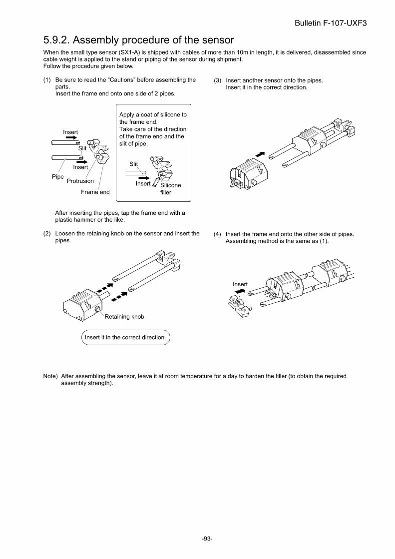
-93-
5.9.2. Assembly procedure of the sensor When the small type sensor (SX1-A) is shipped with cables of more than 10m in length, it is delivered, disassembled since cable weight is applied to the stand or piping of the sensor during shipment. Follow the procedure given below.
(1) Be sure to read the “Cautions” before assembling the parts. Insert the frame end onto one side of 2 pipes.
Insert
Insert Silicone
filler
Insert
PipeProtrusion
Frame end
Slit
Slit
Apply a coat of silicone to
the frame end.
Take care of the direction
of the frame end and the
slit of pipe.
After inserting the pipes, tap the frame end with a plastic hammer or the like.
(2) Loosen the retaining knob on the sensor and insert the pipes.
Retaining knob
Insert it in the correct direction.
(3) Insert another sensor onto the pipes. Insert it in the correct direction.
(4) Insert the frame end onto the other side of pipes. Assembling method is the same as (1).
Insert
Note) After assembling the sensor, leave it at room temperature for a day to harden the filler (to obtain the required assembly strength).
Bulletin F-107-UXF3
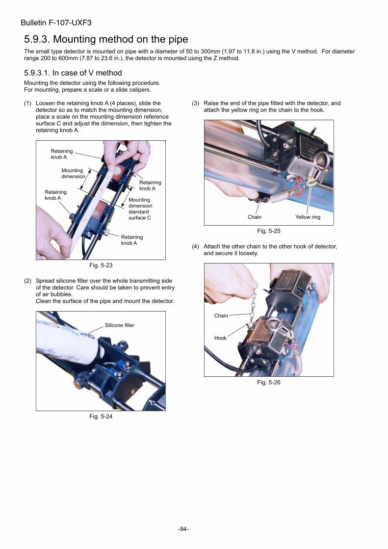
-94-
5.9.3. Mounting method on the pipe The small type detector is mounted on pipe with a diameter of 50 to 300mm (1.97 to 11.8 in.) using the V method. For diameterrange 200 to 600mm (7.87 to 23.6 in.), the detector is mounted using the Z method.
5.9.3.1. In case of V method
Mounting the detector using the following procedure. For mounting, prepare a scale or a slide calipers.
(1) Loosen the retaining knob A (4 places), slide the detector so as to match the mounting dimension, place a scale on the mounting dimension reference surface C and adjust the dimension, then tighten the retaining knob A.
Fig. 5-23
(2) Spread silicone filler over the whole transmitting side of the detector. Care should be taken to prevent entry of air bubbles. Clean the surface of the pipe and mount the detector.
Fig. 5-24
(3) Raise the end of the pipe fitted with the detector, and attach the yellow ring on the chain to the hook.
Fig. 5-25
(4) Attach the other chain to the other hook of detector, and secure it loosely.
Fig. 5-26
Retaining knob A
Mountingdimension
Mountingdimensionstandard surface C
Retaining knob A
Retaining knob A
Retaining knob A
Silicone filler
Chain Yellow ring
Chain
Hook
Bulletin F-107-UXF3
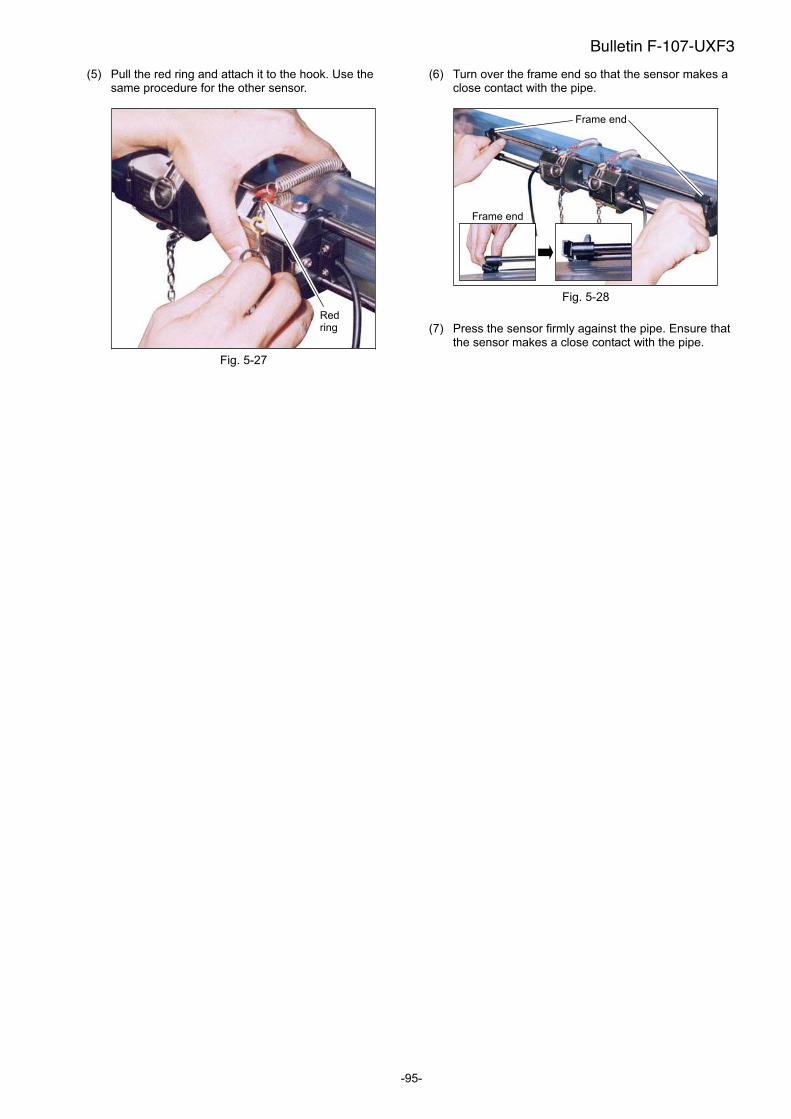
-95-
(5) Pull the red ring and attach it to the hook. Use the same procedure for the other sensor.
Fig. 5-27
(6) Turn over the frame end so that the sensor makes a close contact with the pipe.
Fig. 5-28
(7) Press the sensor firmly against the pipe. Ensure that the sensor makes a close contact with the pipe.
Redring
Frame end
Frame end
Bulletin F-107-UXF3
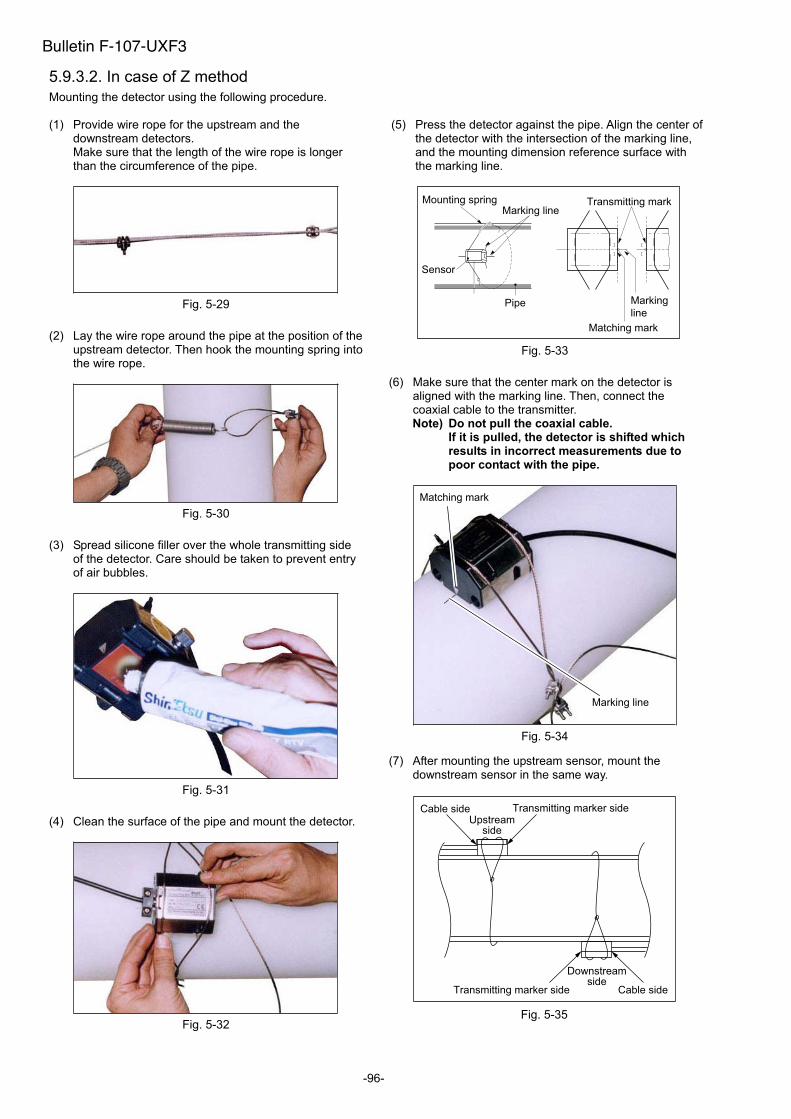
-96-
5.9.3.2. In case of Z method
Mounting the detector using the following procedure.
(1) Provide wire rope for the upstream and the downstream detectors. Make sure that the length of the wire rope is longer than the circumference of the pipe.
Fig. 5-29
(2) Lay the wire rope around the pipe at the position of the upstream detector. Then hook the mounting spring into the wire rope.
Fig. 5-30
(3) Spread silicone filler over the whole transmitting side of the detector. Care should be taken to prevent entry of air bubbles.
Fig. 5-31
(4) Clean the surface of the pipe and mount the detector.
Fig. 5-32
(5) Press the detector against the pipe. Align the center of the detector with the intersection of the marking line, and the mounting dimension reference surface with the marking line.
Transmitting mark
Matching mark
Marking
line
Sensor
Marking lineMounting spring
Pipe
Fig. 5-33
(6) Make sure that the center mark on the detector is aligned with the marking line. Then, connect the coaxial cable to the transmitter. Note) Do not pull the coaxial cable.
If it is pulled, the detector is shifted which results in incorrect measurements due to poor contact with the pipe.
Fig. 5-34
(7) After mounting the upstream sensor, mount the downstream sensor in the same way.
Upstreamside
Cable side
Cable sideTransmitting marker side
Transmitting marker side
Downstreamside
Fig. 5-35
Matching mark
Marking line
Bulletin F-107-UXF3
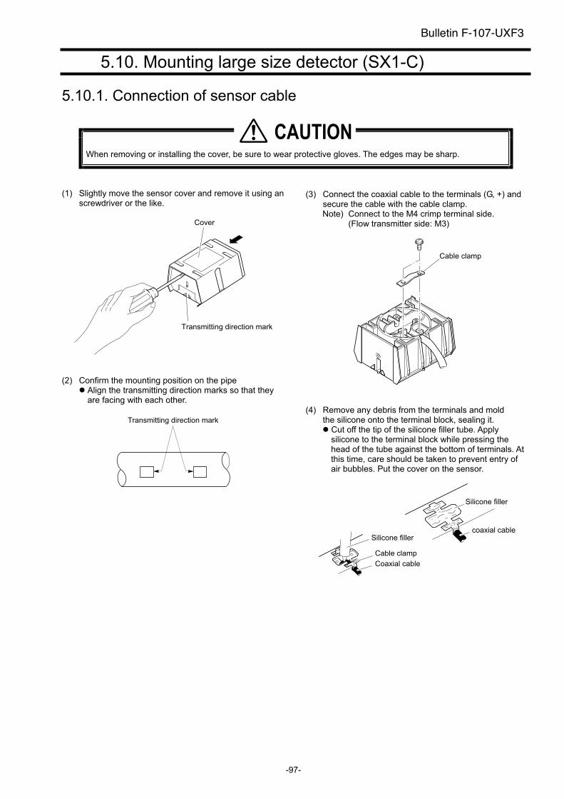
-97-
5.10. Mounting large size detector (SX1-C)
5.10.1. Connection of sensor cable
When removing or installing the cover, be sure to wear protective gloves. The edges may be sharp.
(1) Slightly move the sensor cover and remove it using an screwdriver or the like.
Cover
Transmitting direction mark
(2) Confirm the mounting position on the pipe Align the transmitting direction marks so that they are facing with each other.
Transmitting direction mark
(3) Connect the coaxial cable to the terminals (G, +) and secure the cable with the cable clamp. Note) Connect to the M4 crimp terminal side.
(Flow transmitter side: M3)
Cable clamp
(4) Remove any debris from the terminals and mold the silicone onto the terminal block, sealing it.
Cut off the tip of the silicone filler tube. Apply silicone to the terminal block while pressing the head of the tube against the bottom of terminals. At this time, care should be taken to prevent entry of air bubbles. Put the cover on the sensor.
Silicone filler
coaxial cableSilicone filler
Cable clamp
Coaxial cable
�������
Bulletin F-107-UXF3
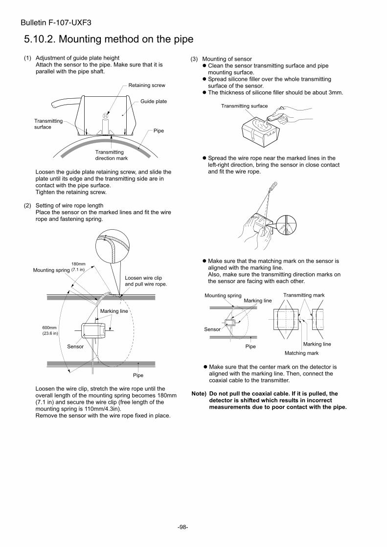
-98-
5.10.2. Mounting method on the pipe
(1) Adjustment of guide plate height Attach the sensor to the pipe. Make sure that it is parallel with the pipe shaft.
Pipe
Guide plate
Retaining screw
Transmitting
surface
Transmitting
direction mark
Loosen the guide plate retaining screw, and slide the plate until its edge and the transmitting side are in contact with the pipe surface. Tighten the retaining screw.
(2) Setting of wire rope length Place the sensor on the marked lines and fit the wire rope and fastening spring.
Sensor
Marking line
Mounting spring
Loosen wire clip
and pull wire rope.
Pipe
Loosen the wire clip, stretch the wire rope until the overall length of the mounting spring becomes 180mm(7.1 in) and secure the wire clip (free length of the mounting spring is 110mm/4.3in). Remove the sensor with the wire rope fixed in place.
(3) Mounting of sensor Clean the sensor transmitting surface and pipe mounting surface. Spread silicone filler over the whole transmitting surface of the sensor. The thickness of silicone filler should be about 3mm.
Transmitting surface
Spread the wire rope near the marked lines in the left-right direction, bring the sensor in close contact and fit the wire rope.
Make sure that the matching mark on the sensor is aligned with the marking line. Also, make sure the transmitting direction marks on the sensor are facing with each other.
Transmitting mark
Matching mark
Marking line
Sensor
Marking lineMounting spring
Pipe
Make sure that the center mark on the detector is aligned with the marking line. Then, connect the coaxial cable to the transmitter.
Note) Do not pull the coaxial cable. If it is pulled, the detector is shifted which results in incorrect measurements due to poor contact with the pipe.
Bulletin F-107-UXF3
180mm
(7.1 in)
600mm
(23.6 in)
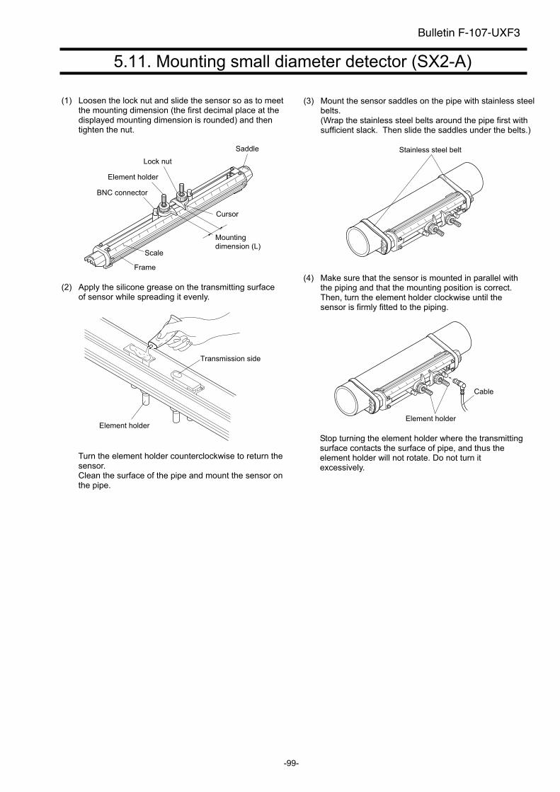
-99-
5.11. Mounting small diameter detector (SX2-A)
(1) Loosen the lock nut and slide the sensor so as to meet the mounting dimension (the first decimal place at the displayed mounting dimension is rounded) and then tighten the nut.
Element holder
Lock nut
Saddle
Scale
Cursor
Mounting
dimension (L)
Frame
BNC connector
(2) Apply the silicone grease on the transmitting surface of sensor while spreading it evenly.
Transmission side
Element holder
Turn the element holder counterclockwise to return the sensor. Clean the surface of the pipe and mount the sensor on the pipe.
(3) Mount the sensor saddles on the pipe with stainless steelbelts.(Wrap the stainless steel belts around the pipe first with sufficient slack. Then slide the saddles under the belts.)
Stainless steel belt
(4) Make sure that the sensor is mounted in parallel with the piping and that the mounting position is correct. Then, turn the element holder clockwise until the sensor is firmly fitted to the piping.
Element holder
Cable
Stop turning the element holder where the transmitting surface contacts the surface of pipe, and thus the element holder will not rotate. Do not turn it excessively.
Bulletin F-107-UXF3
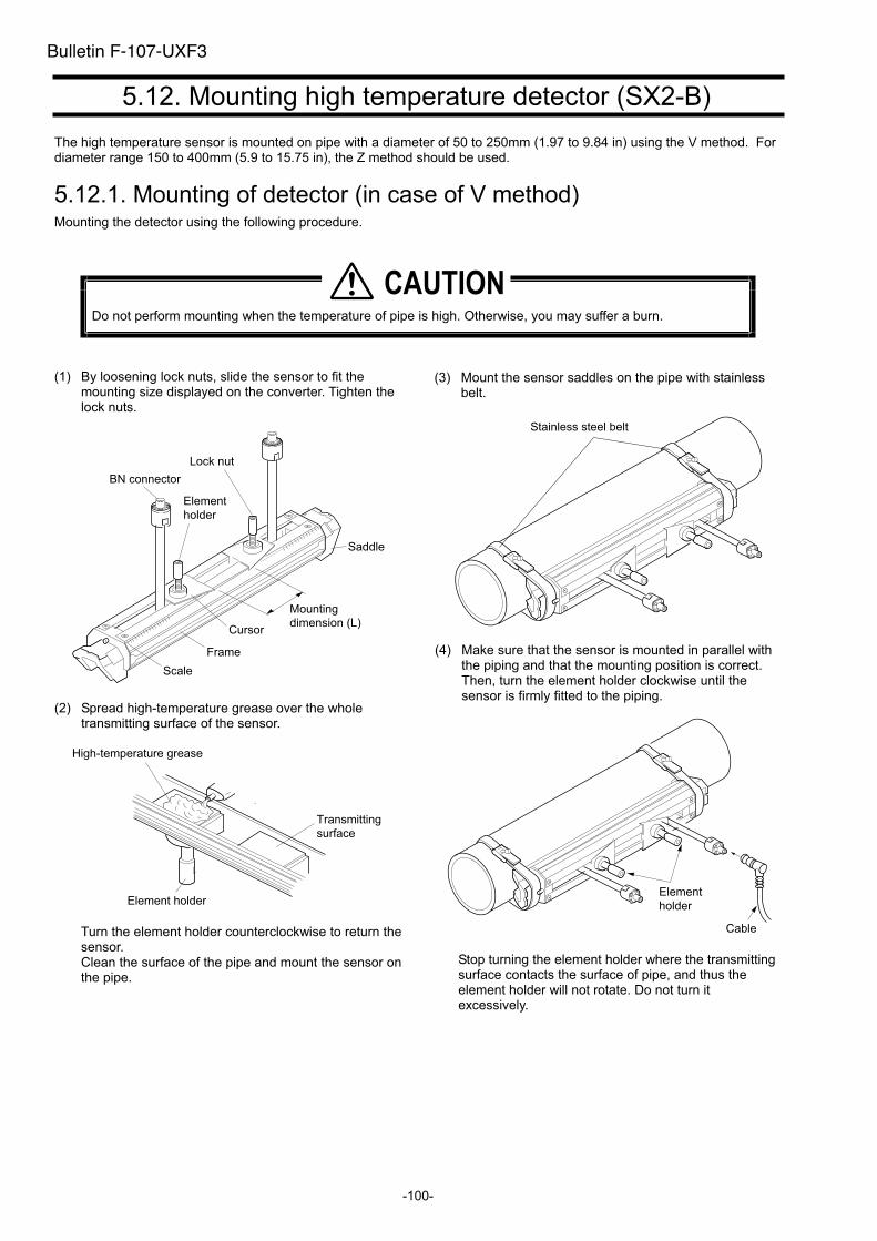
-100-
5.12. Mounting high temperature detector (SX2-B)
The high temperature sensor is mounted on pipe with a diameter of 50 to 250mm (1.97 to 9.84 in) using the V method. Fordiameter range 150 to 400mm (5.9 to 15.75 in), the Z method should be used.
5.12.1. Mounting of detector (in case of V method) Mounting the detector using the following procedure.
Do not perform mounting when the temperature of pipe is high. Otherwise, you may suffer a burn.
(1) By loosening lock nuts, slide the sensor to fit the mounting size displayed on the converter. Tighten the lock nuts.
BN connector
Element
holder
Lock nut
Saddle
Cursor
Frame
Scale
Mounting
dimension (L)
(2) Spread high-temperature grease over the whole transmitting surface of the sensor.
Transmitting
surface
Element holder
High-temperature grease
Turn the element holder counterclockwise to return the sensor. Clean the surface of the pipe and mount the sensor on the pipe.
(3) Mount the sensor saddles on the pipe with stainless belt.
Stainless steel belt
(4) Make sure that the sensor is mounted in parallel with the piping and that the mounting position is correct. Then, turn the element holder clockwise until the sensor is firmly fitted to the piping.
Element
holder
Cable
Stop turning the element holder where the transmitting surface contacts the surface of pipe, and thus the element holder will not rotate. Do not turn it excessively.
�������
Bulletin F-107-UXF3
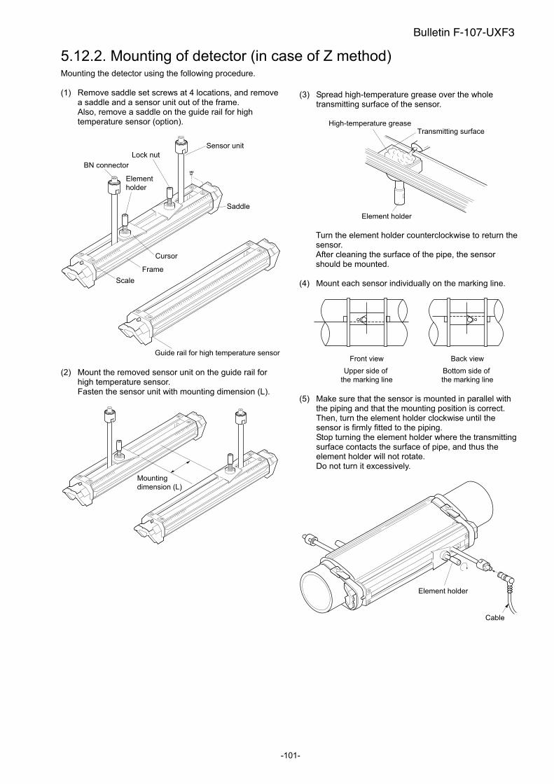
-101-
5.12.2. Mounting of detector (in case of Z method) Mounting the detector using the following procedure.
(1) Remove saddle set screws at 4 locations, and remove a saddle and a sensor unit out of the frame. Also, remove a saddle on the guide rail for high temperature sensor (option).
BN connector
Element
holder
Lock nut
Saddle
Cursor
Frame
Scale
Guide rail for high temperature sensor
Sensor unit
(2) Mount the removed sensor unit on the guide rail for high temperature sensor. Fasten the sensor unit with mounting dimension (L).
Mounting
dimension (L)
(3) Spread high-temperature grease over the whole transmitting surface of the sensor.
Element holder
High-temperature greaseTransmitting surface
Turn the element holder counterclockwise to return the sensor. After cleaning the surface of the pipe, the sensor should be mounted.
(4) Mount each sensor individually on the marking line.
Front view Back view
Upper side of
the marking line
Bottom side of
the marking line
(5) Make sure that the sensor is mounted in parallel with the piping and that the mounting position is correct. Then, turn the element holder clockwise until the sensor is firmly fitted to the piping. Stop turning the element holder where the transmitting surface contacts the surface of pipe, and thus the element holder will not rotate. Do not turn it excessively.
Element holder
Cable
Bulletin F-107-UXF3
-102-
6. CHECK AND MAINTENANCE
6.1. Daily Check
Visually check the following items.
Whether flow transmitter cover screws are loose. Tighten.
Whether cable glands are loose. Tighten.
Whether detector mounting band is loose. Stretch.
Whether received wave is abnormal (LED lit red). Check whether piping is filled or not. Remove bubbles or foreign
matters, if mixed in measurement pipe. Also check if detector mounting and wiring are set up properly.
6.2. Periodic Inspection
6.2.1. Checking zero point Stop the fluid flow, fill the measurement pipe fully, and check the zero point.
6.2.2. Reapplying grease When using grease for the acoustic couplant, reapply it on the transmission surface of the sensor unit approximately once every 6 months. Note) Silicone rubber need not be reapplied.
Bulletin F-107-UXF3
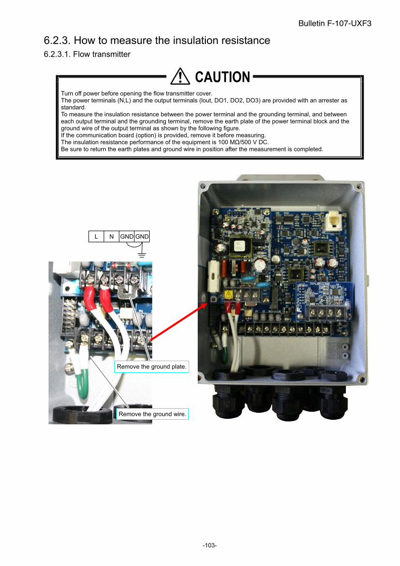
-103-
6.2.3. How to measure the insulation resistance
6.2.3.1. Flow transmitter
Turn off power before opening the flow transmitter cover. The power terminals (N,L) and the output terminals (lout, DO1, DO2, DO3) are provided with an arrester as standard. To measure the insulation resistance between the power terminal and the grounding terminal, and between each output terminal and the grounding terminal, remove the earth plate of the power terminal block and the ground wire of the output terminal as shown by the following figure. If the communication board (option) is provided, remove it before measuring. The insulation resistance performance of the equipment is 100 M /500 V DC. Be sure to return the earth plates and ground wire in position after the measurement is completed.
�������
L N GND GND
Remove the ground plate.
Remove the ground wire.
Bulletin F-107-UXF3

Bulletin F-107-UXF3
(Page intentionally blank)

-105-
6.3. How to replace the fuse
Be sure to turn off the power before replacing the fuse. Fuse specifications (1) AC power supply (100V and 200V): 5.2mm (diameter) × 20mm (long), 250V, 0.5A.
As represented by F. T. I. Co., Ltd. FGMB: 250V, 0.5A. (2) DC power supply: 5.2mm (diameter) × 20mm (long), 250V, 1A.
As represented by F. T. I. Co., Ltd. FGMB: 250V, 1A.
6.3.1. Flow transmitter : UXF3 (1) Opening the cover after turning off power.
Loosen 4 screws from the flow transmitter front, and open the cover. (2) Replace the fuse.
Detach the fuse holder from the power supply board, and replace the fuse. Then, return the fuse holder in place. (3) Closing the cover.
Close the cover, and tighten 4 screws.
Turn on power only after closing the cover.
Bulletin F-107-UXF3

Bulletin F-107-UXF3
(Page intentionally blank)

-107-
6.4. How to replace the relay
DO3 is a relay contact, whose service life is 200,000 times (under rated load). Replace it before the end of its life estimating the number of contact operations. For replacement part ordering information, contact the manufacturer.
6.4.1. Flow transmitter : UXF3 [How to replace] (1) Open the cover after turning off power. (2) As shown by the following photo, pull out the card relay from socket. (3) Set a new card relay into the socket. Push it enough to engage the card relay claws. (4) Close the cover and turn on the power. (5) Set the maintenance mode to "STATUS OUTPUT", and check the relay “ON” and “OFF” actions.
Be sure to turn off the power before opening the cover. The unit containts high voltage.
Relay removing procedures
Push up the card relay bottom.
Push the card relay top from socket.
Pull out the card relay from socket.
Relay contact

Bulletin F-107-UXF3
(Page intentionally blank)

-109-
6.5. How to replace the LCD
The nominal service life of the LCD is 7 years. The contrast gradually deteriorates with time. Replace it about 5 years after starting its use.
6.5.1. Flow transmitter : UXF3 [How to replace] (1) Open the cover after turning OFF power. (2) Remove the flat cable connector. (3) Loosen 6 screws from the LCD unit. (4) Mount a new LCD unit (see parts list), inserting the operation keys and LED properly into the cover holes. Take care not
to allow interference by the cover. (5) Connect the flat cable connector. (Insert it securely all the way.) (6) Close the cover and turn on the power. (7) Check that the LCD display and key operation are functioning correctly.
Be sure to turn off the power before opening the cover. The unit containts high voltage.
LCD unit
Flat cable
Screw Screw

-110-
Bulletin F-107-UXF3
(Page intentionally blank)
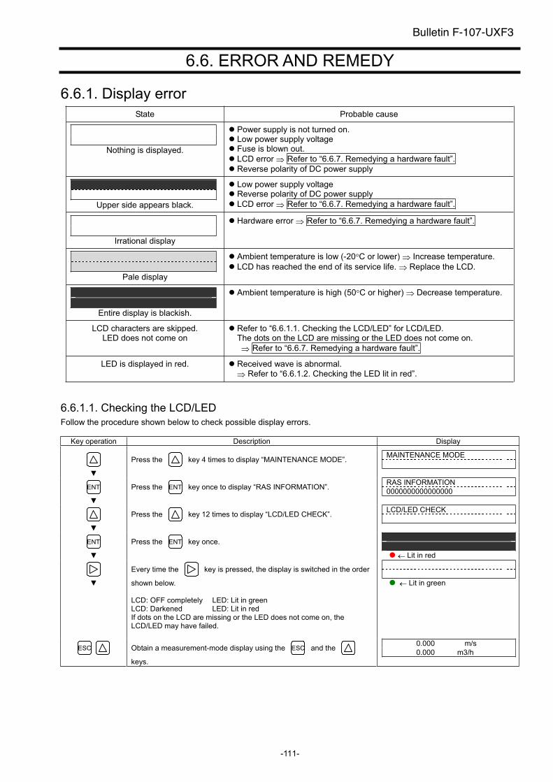
-111-
6.6. ERROR AND REMEDY
6.6.1. Display error
State Probable cause
Nothing is displayed.
Power supply is not turned on. Low power supply voltage Fuse is blown out.
LCD error Refer to “6.6.7. Remedying a hardware fault”.
Reverse polarity of DC power supply
Upper side appears black.
Low power supply voltage Reverse polarity of DC power supply
LCD error Refer to “6.6.7. Remedying a hardware fault”.
Irrational display
Hardware error Refer to “6.6.7. Remedying a hardware fault”.
Pale display
Ambient temperature is low (-20 C or lower) Increase temperature.
LCD has reached the end of its service life. Replace the LCD.
Entire display is blackish.
Ambient temperature is high (50 C or higher) Decrease temperature.
LCD characters are skipped. LED does not come on
Refer to “6.6.1.1. Checking the LCD/LED” for LCD/LED. The dots on the LCD are missing or the LED does not come on.
Refer to “6.6.7. Remedying a hardware fault”.
LED is displayed in red. Received wave is abnormal.
Refer to “6.6.1.2. Checking the LED lit in red”.
6.6.1.1. Checking the LCD/LED
Follow the procedure shown below to check possible display errors.
Key operation Description Display
Press the key 4 times to display “MAINTENANCE MODE”. MAINTENANCE MODE
ENT Press the ENT key once to display “RAS INFORMATION”. RAS INFORMATION
0000000000000000
Press the key 12 times to display “LCD/LED CHECK”. LCD/LED CHECK
ENT Press the ENT key once.
Lit in red
Every time the key is pressed, the display is switched in the order
shown below.
LCD: OFF completely LED: Lit in green LCD: Darkened LED: Lit in red If dots on the LCD are missing or the LED does not come on, the LCD/LED may have failed.
Lit in green
ESC Obtain a measurement-mode display using the ESC and the
keys.
0.000 m/s
0.000 m3/h
Bulletin F-107-UXF3

-112-
6.6.1.2. Checking the LED lit in red
Check the LED lit in red, following the procedure shown below.
1
Error status: Received wave is abnormal Received wave fluctuates, noise
Cause and remedy: Bubbles or foreign objects included in the fluid
Stop the flow, and if the measurement is found to be
normal, there is great possibility that air bubbles are contained. Remove bubbles in such cases.
Noise Check ultrasonic signals for existence of noise using
an oscilloscope. Remove noise if found by performing grounding, etc. See “6.6.6.Checking received waveforms”.
LED lit in red
Check the RAS information
The 2nd or 3rd from the left is 1. 0110000000000000
Check AGC_U, AGC_D.
The 7th from the left is 1. 0000001000000000
The 4th or 5th from the left is 1. 0001100000000000
Error status: No waves are received. Waves are being searched. (Window scanning)
Cause and remedy: Transmission error due to scale or rust within piping
Move the mounting position of the detector.
Break of signal cable Repair or replace the signal cable.
Detector mounting failure Remount the detector.
Transmitter circuit failure or detector failure See “6.6.7. Remedying a hardware fault”
Error status: Device error, Ultrasonic send/receive signals cannot be collected.
Cause and remedy: Abnormality of measuring circuit
Turn the power OFF then ON again.
If the instrument does not recover, transmitter circuit is failure. See “6.6.7. Remedying a hardware fault”.
Error status:
Signal error Weak receiving waveform, Signal
configuration error Signal range over Signal position is abnormal.
Cause and remedy: Detector mounting failure Remount the detector.
Incorrect detector selection
Change the setting for the detector selection, and
remount the detector. Transmission error due to scale or rust within piping
Move the mounting position of the detector.
Incorrect piping data input
Enter the correct data, and remount the detector.
1
Error status: Malfunction Cause and remedy: LED failure See “6.6.1.1.Checking the LCD/LED”
and “6.6.7.Remedying a hardware fault”.
YES
1
The 6th from the left is 1. 0000010000000000
Check P/H_U, P/H_D.
The 8th from the left is 1. 0000000100000000
35% or less
1
The values fluctuate or is outside the range
of 5528 to 6758.
Bulletin F-107-UXF3
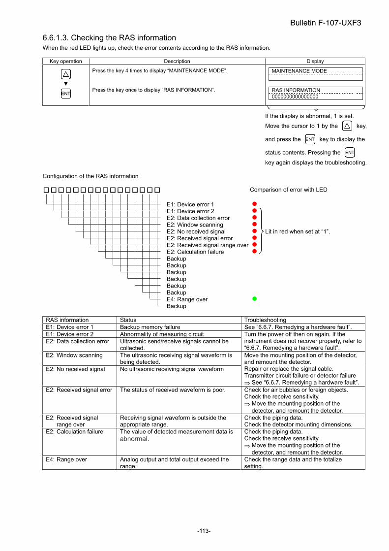
-113-
6.6.1.3. Checking the RAS information
When the red LED lights up, check the error contents according to the RAS information.
Key operation Description Display
Press the key 4 times to display “MAINTENANCE MODE”. MAINTENANCE MODE
ENTPress the key once to display “RAS INFORMATION”. RAS INFORMATION
0000000000000000
If the display is abnormal, 1 is set.
Move the cursor to 1 by the key,
and press the ENT key to display the
status contents. Pressing the ENT
key again displays the troubleshooting.
Configuration of the RAS information
Comparison of error with LED
E1: Device error 1
E1: Device error 2
E2: Data collection error
E2: Window scanning
E2: No received signal
E2: Received signal error
E2: Received signal range over
E2: Calculation failure
Lit in red when set at “1”.
Backup
Backup
Backup
Backup
Backup
Backup
E4: Range over
Backup
RAS information Status Troubleshooting
E1: Device error 1 Backup memory failure See “6.6.7. Remedying a hardware fault”.
E1: Device error 2 Abnormality of measuring circuit
E2: Data collection error Ultrasonic send/receive signals cannot be collected.
Turn the power off then on again. If the instrument does not recover properly, refer to “6.6.7. Remedying a hardware fault”.
E2: Window scanning The ultrasonic receiving signal waveform is being detected.
E2: No received signal No ultrasonic receiving signal waveform
Move the mounting position of the detector, and remount the detector. Repair or replace the signal cable. Transmitter circuit failure or detector failure
See “6.6.7. Remedying a hardware fault”.
E2: Received signal error The status of received waveform is poor. Check for air bubbles or foreign objects. Check the receive sensitivity.
Move the mounting position of the
detector, and remount the detector.
E2: Received signal range over
Receiving signal waveform is outside the appropriate range.
Check the piping data. Check the detector mounting dimensions.
E2: Calculation failure The value of detected measurement data is
abnormal.Check the piping data. Check the receive sensitivity.
Move the mounting position of the
detector, and remount the detector.
E4: Range over Analog output and total output exceed the range.
Check the range data and the totalize setting.
Bulletin F-107-UXF3
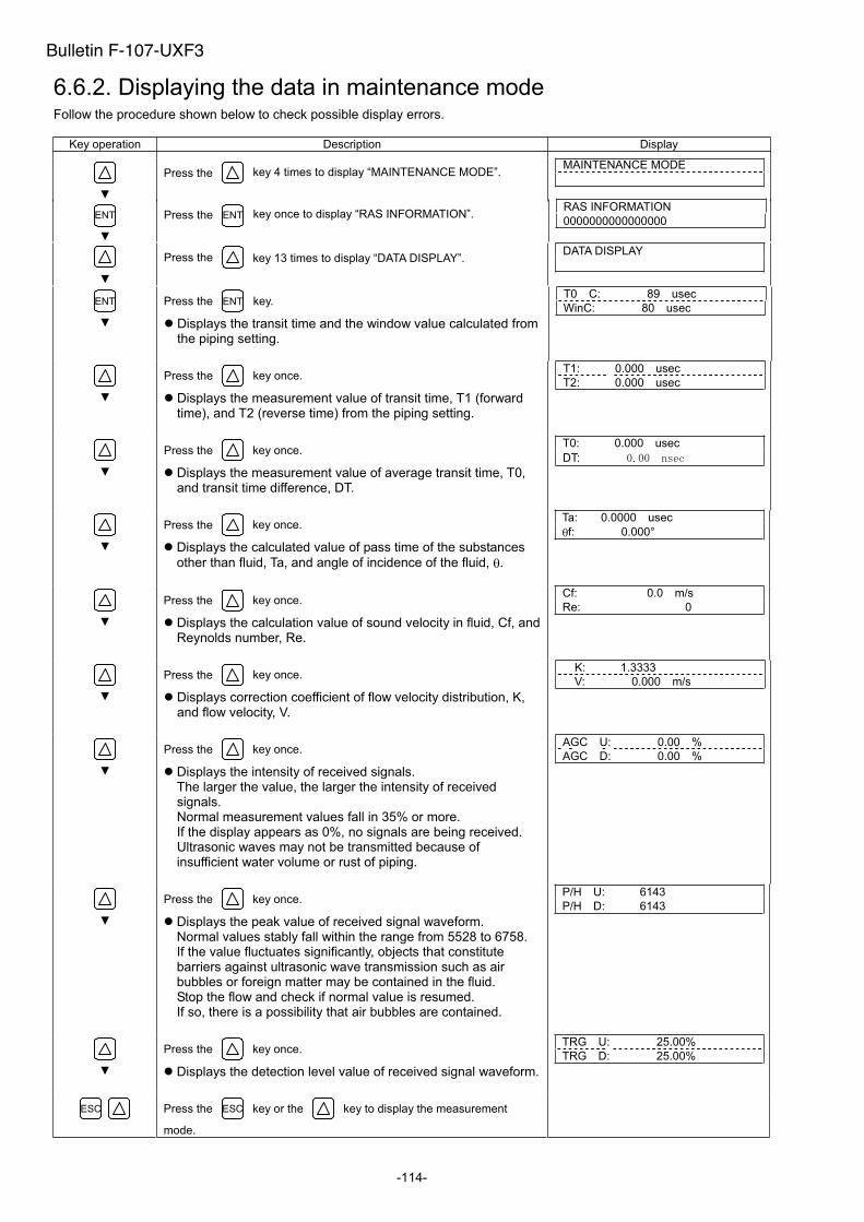
-114-
6.6.2. Displaying the data in maintenance mode Follow the procedure shown below to check possible display errors.
Key operation Description Display
Press the key 4 times to display “MAINTENANCE MODE”. MAINTENANCE MODE
ENT Press the ENT key once to display “RAS INFORMATION”. RAS INFORMATION
0000000000000000
Press the key 13 times to display “DATA DISPLAY”. DATA DISPLAY
ENT Press the ENT key.
Displays the transit time and the window value calculated from the piping setting.
T0 C: 89 usec
WinC: 80 usec
Press the key once.
Displays the measurement value of transit time, T1 (forward time), and T2 (reverse time) from the piping setting.
T1: 0.000 usec
T2: 0.000 usec
Press the key once.
Displays the measurement value of average transit time, T0, and transit time difference, DT.
T0: 0.000 usec
DT:
Press the key once.
Displays the calculated value of pass time of the substances
other than fluid, Ta, and angle of incidence of the fluid, .
Ta: 0.0000 usec
f: 0.000°
Press the key once.
Displays the calculation value of sound velocity in fluid, Cf, and Reynolds number, Re.
Cf: 0.0 m/s
Re: 0
Press the key once.
Displays correction coefficient of flow velocity distribution, K, and flow velocity, V.
K: 1.3333
V: 0.000 m/s
Press the key once.
Displays the intensity of received signals. The larger the value, the larger the intensity of received signals.Normal measurement values fall in 35% or more. If the display appears as 0%, no signals are being received. Ultrasonic waves may not be transmitted because of insufficient water volume or rust of piping.
AGC U: 0.00 %
AGC D: 0.00 %
Press the key once.
Displays the peak value of received signal waveform. Normal values stably fall within the range from 5528 to 6758. If the value fluctuates significantly, objects that constitute barriers against ultrasonic wave transmission such as air bubbles or foreign matter may be contained in the fluid. Stop the flow and check if normal value is resumed. If so, there is a possibility that air bubbles are contained.
P/H U: 6143
P/H D: 6143
Press the key once.
Displays the detection level value of received signal waveform.
TRG U: 25.00%
TRG D: 25.00%
ESC Press the ESC key or the key to display the measurement
mode.
Bulletin F-107-UXF3

-115-
6.6.3. Keying is abnormal
Status Probable cause
No response is made to key input. Hard failure Refer to “6.6.7. Remedying a hardware fault”.
Certain key is not responded. Action is not as defined.
Bulletin F-107-UXF3
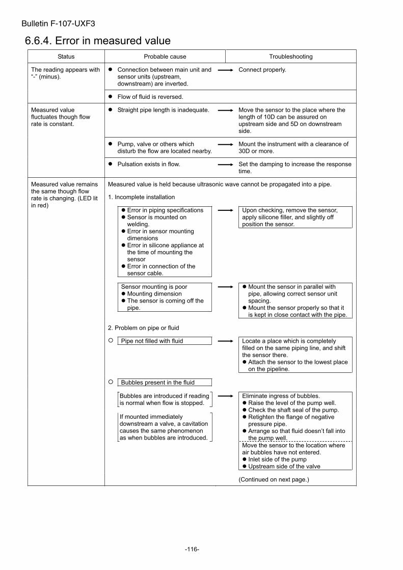
-116-
6.6.4. Error in measured value
Status Probable cause Troubleshooting
Connection between main unit and sensor units (upstream, downstream) are inverted.
Connect properly. The reading appears with “-” (minus).
Flow of fluid is reversed.
Straight pipe length is inadequate. Move the sensor to the place where the length of 10D can be assured on upstream side and 5D on downstream side.
Pump, valve or others which disturb the flow are located nearby.
Mount the instrument with a clearance of 30D or more.
Measured value fluctuates though flow rate is constant.
Pulsation exists in flow. Set the damping to increase the response time.
Measured value is held because ultrasonic wave cannot be propagated into a pipe.
1. Incomplete installation
Measured value remains the same though flow rate is changing. (LED lit in red)
Error in piping specifications Sensor is mounted on welding. Error in sensor mounting dimensions Error in silicone appliance at the time of mounting the sensor Error in connection of the sensor cable.
Upon checking, remove the sensor, apply silicone filler, and slightly off position the sensor.
Sensor mounting is poor Mounting dimension The sensor is coming off the pipe.
Mount the sensor in parallel with pipe, allowing correct sensor unit spacing. Mount the sensor properly so that it is kept in close contact with the pipe.
2. Problem on pipe or fluid
Pipe not filled with fluid Locate a place which is completely filled on the same piping line, and shift the sensor there.
Attach the sensor to the lowest place on the pipeline.
Bubbles present in the fluid
Bubbles are introduced if reading is normal when flow is stopped.
If mounted immediately downstream a valve, a cavitation causes the same phenomenon as when bubbles are introduced.
Eliminate ingress of bubbles. Raise the level of the pump well. Check the shaft seal of the pump. Retighten the flange of negative pressure pipe. Arrange so that fluid doesn’t fall into the pump well.
Move the sensor to the location where air bubbles have not entered.
Inlet side of the pump Upstream side of the valve
(Continued on next page.)
Bulletin F-107-UXF3
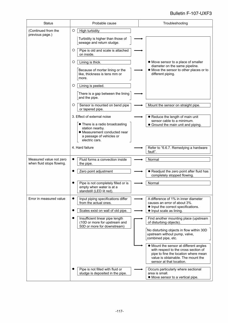
-117-
Status Probable cause Troubleshooting
High turbidity (Continued from the previous page.)
Turbidity is higher than those of sewage and return sludge.
Pipe is old and scale is attached on inside.
Lining is thick.
Because of mortar lining or the like, thickness is tens mm or more.
Lining is peeled.
There is a gap between the lining and the pipe.
Move sensor to a place of smaller diameter on the same pipeline. Move the sensor to other places or to different piping.
Sensor is mounted on bend pipe or tapered pipe.
Mount the sensor on straight pipe.
3. Effect of external noise
There is a radio broadcasting station nearby. Measurement conducted near a passage of vehicles or electric cars.
Reduce the length of main unit sensor cable to a minimum. Ground the main unit and piping.
4. Hard failure Refer to “6.6.7. Remedying a hardware fault”.
Fluid forms a convection inside the pipe.
Normal
Zero point adjustment Readjust the zero point after fluid has completely stopped flowing.
Measured value not zero when fluid stops flowing.
Pipe is not completely filled or is empty when water is at a standstill (LED lit red).
Normal
Error in measured value Input piping specifications differ from the actual ones.
Scales exist on wall of old pipe.
A difference of 1% in inner diameter causes an error of about 3%.
Input the correct specifications. Input scale as lining.
Find another mounting place (upstream of disturbing objects).
Insufficient linear pipe length (10D or more for upstream and 50D or more for downstream)
No disturbing objects in flow within 30D upstream without pump, valve, combined pipe, etc.
Mount the sensor at different angles with respect to the cross section of pipe to fine the location where mean value is obtainable. The mount the sensor at that location.
Pipe is not filled with fluid or sludge is deposited in the pipe.
Occurs particularly where sectional area is small.
Move sensor to a vertical pipe.
Bulletin F-107-UXF3
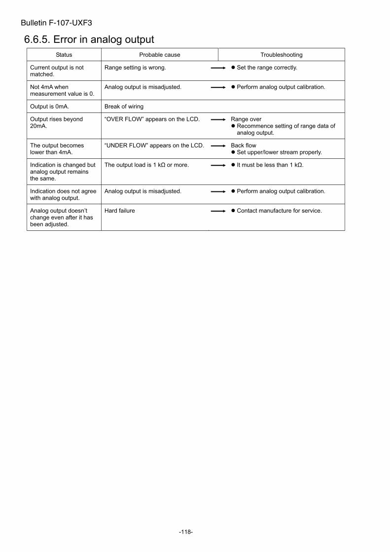
-118-
6.6.5. Error in analog output
Status Probable cause Troubleshooting
Current output is not matched.
Range setting is wrong. Set the range correctly.
Not 4mA when measurement value is 0.
Analog output is misadjusted. Perform analog output calibration.
Output is 0mA. Break of wiring
Output rises beyond 20mA.
“OVER FLOW” appears on the LCD. Range over Recommence setting of range data of analog output.
The output becomes lower than 4mA.
“UNDER FLOW” appears on the LCD. Back flow Set upper/lower stream properly.
Indication is changed but analog output remains the same.
The output load is 1 k or more. It must be less than 1 k .
Indication does not agree with analog output.
Analog output is misadjusted. Perform analog output calibration.
Analog output doesn’t change even after it has been adjusted.
Hard failure Contact manufacture for service.
Bulletin F-107-UXF3
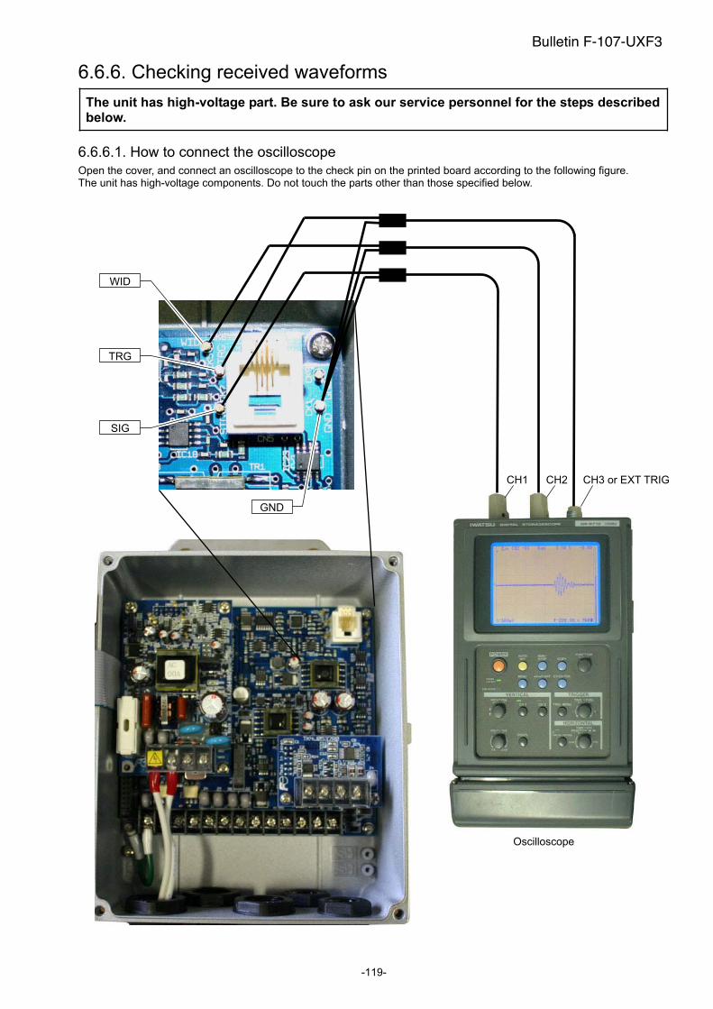
-119-
6.6.6. Checking received waveforms
The unit has high-voltage part. Be sure to ask our service personnel for the steps described below.
6.6.6.1. How to connect the oscilloscope
Open the cover, and connect an oscilloscope to the check pin on the printed board according to the following figure. The unit has high-voltage components. Do not touch the parts other than those specified below.
WID
TRG
SIG
GND
CH1 CH2 CH3 or EXT TRIG
Oscilloscope
Bulletin F-107-UXF3

-120-
6.6.6.2. Checking sending/receiving
Monitor the waveform, and check the status of received waveform.
a) Normal status
Transmitted/received waveform for both forward and reverse directions
CH1 : 500mV/divCH2 : 5V/div
Point1. Check that overall noise level is kept at 0.3
Vp-p or lower.
Relationship between the received waveform and the sampling window
CH1 (SMP)
CH2 (SIG)
Magnified
Noise level
Pipe inside echoic wave (generated only in case of V method mounting). In mounting by the Z method, there is no echoic wave.
Forward direction: Sends from the upstream of the detector, and receives at the downstream.
Reverse direction: Reverse procedure of forward direction.
Sampling window
CH2 (WID)
CH1 (SIG)
CH1 : 500mV/divCH2 : 5V/div
Point1. There is the received waveform for SMP of
CH1 in front of the center of LOW. 2. The received waveform is approximately
0.75Vo-p.
Magnified view of signals
CH1 : 500mV/div
Point1. Startup is kept within 3 to 6 waves. 2. The peak (amplitude) does not fluctuate.
If the peak fluctuates vertically, air may be mixed in.
3. The time base must not fluctuate. If it does, there may be influence by turbulent flow or drift current.
The received waveform controls the peak to be approximately 1.5Vp-p.
Peak fluctuation
Time base fluctuation
Forward direction Forward directionReverse direction
Received waveformTransmitted waveform
Bulletin F-107-UXF3
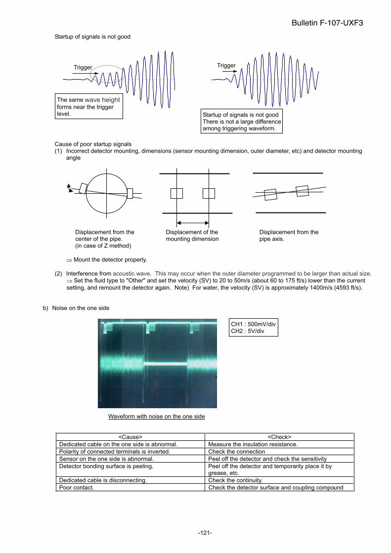
-121-
Startup of signals is not good
Cause of poor startup signals (1) Incorrect detector mounting, dimensions (sensor mounting dimension, outer diameter, etc) and detector mounting
angle
Mount the detector properly.
(2) Interference from acoustic wave. This may occur when the outer diameter programmed to be larger than actual size.Set the fluid type to "Other" and set the velocity (SV) to 20 to 50m/s (about 60 to 175 ft/s) lower than the current
setting, and remount the detector again. Note) For water, the velocity (SV) is approximately 1400m/s (4593 ft/s).
b) Noise on the one side
<Cause> <Check>
Dedicated cable on the one side is abnormal. Measure the insulation resistance.
Polarity of connected terminals is inverted. Check the connection
Sensor on the one side is abnormal. Peel off the detector and check the sensitivity
Detector bonding surface is peeling. Peel off the detector and temporarily place it by grease, etc.
Dedicated cable is disconnecting. Check the continuity.
Poor contact. Check the detector surface and coupling compound
Trigger
The same wave heightforms near the trigger level. Startup of signals is not good
There is not a large difference among triggering waveform.
Trigger
Waveform with noise on the one side
CH1 : 500mV/divCH2 : 5V/div
Displacement from the center of the pipe. (in case of Z method)
Displacement of the mounting dimension
Displacement from the pipe axis.
Bulletin F-107-UXF3

-122-
c) There is white noise all around.
Waveform with the overall noise
d) Pulsed noise is observed.
Waveform with pulsed noise on the signal line
Measurement can be performed if the noise level is smaller than the received waveform level (0.75V0-p).
<Cause> <Check>
Noise is placed on the power line. Check the power line using an oscilloscope, and install a noise-suppression transformer.
Noise is placed on the grounding line (panel earth, etc).
Check the power line using an oscilloscope, and remove the ground wire.
Dedicated cable is picking the inductive noise. Move the flow transmitter near the detector and perform confirmation. Keep the dedicated cable apart from the power cable.
The distance between the detector and the flow transmitter is long, and dedicated cable length is long.
Perform grounding according to the figure below.
Insufficient sensitivity Signal power (AGC_U, AGC_D) 35% or less
Change the detector.
SX1-A, SX2-A SX1-B
SX1-B SX1-C
6.6.7. Remedying a hardware fault If the hardware is found faulty as a result of Section 6.6.1 to Section 6.6.6 above, provide specific details to the manufacturer.
Flow transmitter
Detector
Ground
Outer shielding of the dedicated cable is grounded to the earth.
Ground
Bulletin F-107-UXF3
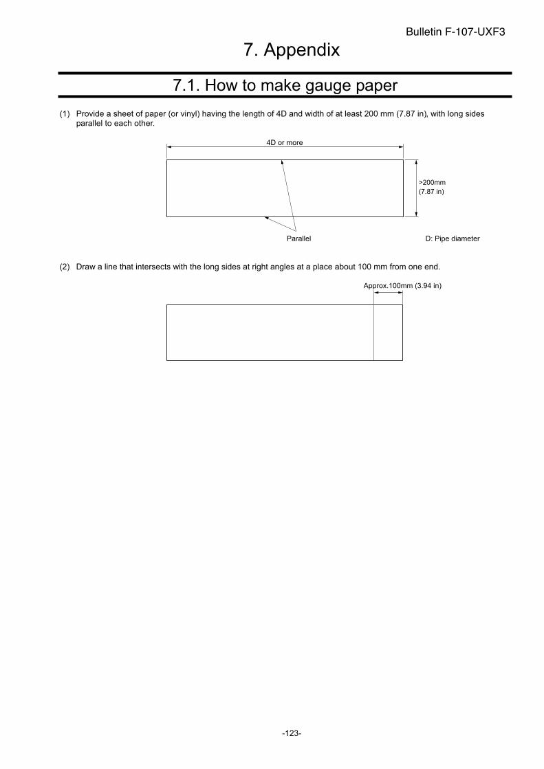
7.1. How to make gauge paper
(1) Provide a sheet of paper (or vinyl) having the length of 4D and width of at least 200 mm (7.87 in), with long sides parallel to each other.
4D or more
D: Pipe diameterParallel
(2) Draw a line that intersects with the long sides at right angles at a place about 100 mm from one end.
Approx.100mm (3.94 in)
-123-
7. Appendix Bulletin F-107-UXF3
>200mm
(7.87 in)
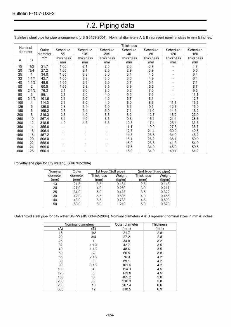
-124-
7.2. Piping data
Stainless steel pipe for pipe arrangement (JIS G3459-2004). Nominal diameters A & B represent nominal sizes in mm & inches.
Thickness Nominal diameter
Schedule 5S
Schedule 10S
Schedule 20S
Schedule 40
Schedule 80
Schedule 120
Schedule 160
A B
Outerdiameter
mm Thickness mm
Thickness mm
Thickness mm
Thickness mm
Thickness mm
Thickness mm
Thickness mm
15 1/2 21.7 1.65 2.1 2.5 2.8 3.7 - 4.7 20 3/4 27.2 1.65 2.1 2.5 2.9 3.9 - 5.5 25 1 34.0 1.65 2.8 3.0 3.4 4.5 - 6.4 32 1 1/4 42.7 1.65 2.8 3.0 3.6 4.9 - 6.4 40 1 1/2 48.6 1.65 2.8 3.0 3.7 5.1 - 7.1 50 2 60.5 1.65 2.8 3.5 3.9 5.5 - 8.7 65 2 1/2 76.3 2.1 3.0 3.5 5.2 7.0 - 9.5 80 3 89.1 2.1 3.0 4.0 5.5 7.6 - 11.1 90 3 1/2 101.6 2.1 3.0 4.0 5.7 8.1 - 12.7 100 4 114.3 2.1 3.0 4.0 6.0 8.6 11.1 13.5 125 5 139.8 2.8 3.4 5.0 6.6 9.5 12.7 15.9 150 6 165.2 2.8 3.4 5.0 7.1 11.0 14.3 18.2 200 8 216.3 2.8 4.0 6.5 8.2 12.7 18.2 23.0 250 10 267.4 3.4 4.0 6.5 9.3 15.1 21.4 28.6 300 12 318.5 4.0 4.5 6.5 10.3 17.4 25.4 33.3 350 14 355.6 - - - 11.1 19.0 27.8 35.7 400 16 406.4 - - - 12.7 21.4 30.9 40.5 450 18 457.2 - - - 14.3 23.8 34.9 45.2 500 20 508.0 - - - 15.1 26.2 38.1 50.0 550 22 558.8 - - - 15.9 28.6 41.3 54.0 600 24 609.6 - - - 17.5 34.0 46.0 59.5 650 26 660.4 - - - 18.9 34.0 49.1 64.2
Polyethylene pipe for city water (JIS K6762-2004)
1st type (Soft pipe) 2nd type (Hard pipe) Nominal diameter
(mm)
Outerdiameter
(mm)Thickness
(mm)Weight (kg/m)
Thickness(mm)
Weight (kg/m)
13 21.5 3.5 0.184 2.5 0.143 20 27.0 4.0 0.269 3.0 0.217 25 34.0 5.0 0.423 3.5 0.322 30 42.0 5.5 0.595 4.0 0.458 40 48.0 6.5 0.788 4.5 0.590 50 60.0 8.0 1.210 5.0 0.829
Galvanized steel pipe for city water SGPW (JIS G3442-2004). Nominal diameters A & B represent nominal sizes in mm & inches.
Nominal diameters
(A) (B)
Outer diameter (mm)
Thickness (mm)
15 1/2 21.7 2.8 20 3/4 27.2 2.8 25 1 34.0 3.2 32 1 1/4 42.7 3.5 40 1 1/2 48.6 3.5 50 2 60.5 3.8 65 2 1/2 76.3 4.2 80 3 89.1 4.2 90 3 1/2 101.6 4.2
100 4 114.3 4.5 125 5 139.8 4.5 150 6 165.2 5.0 200 8 216.3 5.8 250 10 267.4 6.6 300 12 318.5 6.9
Bulletin F-107-UXF3

-125-
Asbestos cement pipe for city water (JIS A5301-1971)
1st type 2nd type 3rd type 4th type
Nominal diameter
(mm)
Thickness of
connected part
(mm)
Outerdiameter of connected
part (mm)
Thickness of
connected part
(mm)
Outerdiameter of connected
part (mm)
Thickness of
connected part
(mm)
Outerdiameter of connected
part (mm)
Thickness of
connected part
(mm)
Outerdiameter of connected
part (mm)
50 10 70 - - - - - - 75 10 95 - - - - - - 100 12 124 10 120 9 118 - - 125 14 153 11 147 9.5 144 - - 150 16 182 12 174 10 170 - - 200 21 242 15 230 13 226 11 222 250 23 296 19 288 15.5 281 12 274 300 26 352 22 344 18 336 14 328 350 30 410 25 400 20.5 391 16 382 400 35 470 29 458 23 446 18 436 450 39 528 32 514 26 502 20 490 500 43 586 35 570 28.5 557 22 544 600 52 704 42 684 34 668 26 652 700 - - 49 798 39 778 30 760 800 - - 56 912 44 888 34 868 900 - - - - 49 998 38 976
1000 - - - - 54 1108 42 1084 1100 - - - - 59 1218 46 1192 1200 - - - - 65 1330 50 1300 1300 - - - - 73 1496 57 1464 1500 - - - - 81 1662 63 1626
Polyethylene pipe for general use (JIS K6761-2004)
1st type (Soft pipe)
2nd type (Hard pipe)Nominal
diameter
Outerdiameter
(mm)Thickness
(mm)Thickness
(mm)
13 21.5 2.7 2.4 20 27.0 3.0 2.4 25 34.0 3.0 2.6 30 42.0 3.5 2.8 40 48.0 3.5 3.0 50 60.0 4.0 3.5 65 76.0 5.0 4.0 75 89.0 5.5 5.0
100 114 6.0 5.5 125 140 6.5 6.5 150 165 7.0 7.0 200 216 - 8.0 250 267 - 9.0 300 318 - 10.0
Hi vinyl chloride pipe (city water pipe size - unit mm)
Nominal diameter
Outerdiameter
Pipethickness
13 18.0 2.5 20 26.0 3.0 25 32.0 3.5 30 38.0 3.5 40 48.0 4.0 50 60.0 4.5 75 89.0 5.8
100 114.0 7.0 125 140.0 7.5 150 165.0 8.5
Hi vinyl chloride pipe (conduit size - unit mm)
Nominal diameter of
pipe
Outerdiameter
Pipethickness
28 34.0 3.0 35 42.0 3.5 41 48.0 3.5 52 60.0 4.0 65 76.0 4.5 78 89.0 5.5
Vertical type cast iron pipe (JIS G5521 - unit mm)
Pipe thickness
TNominal diameter
DNormal
pressure pipe
Low pressure
pipe
Actualouter
diameter D1
75 9.0 - 93.0 100 9.0 - 118.0 150 9.5 9.0 169.0 200 10.0 9.4 220.0 250 10.8 9.8 271.6 300 11.4 10.2 322.8 350 12.0 10.6 374.0 400 12.8 11.0 425.6 450 13.4 11.5 476.8 500 14.0 12.0 528.0 600 15.4 13.0 630.8 700 16.5 13.8 733.0 800 18.0 14.8 836.0 900 19.5 15.5 939.0
1000 22.0 - 1041.0 1100 23.5 - 1144.0 1200 25.0 - 1246.0 1350 27.5 - 1400.0 1500 30.0 - 1554.0
Bulletin F-107-UXF3
(unit:mm)
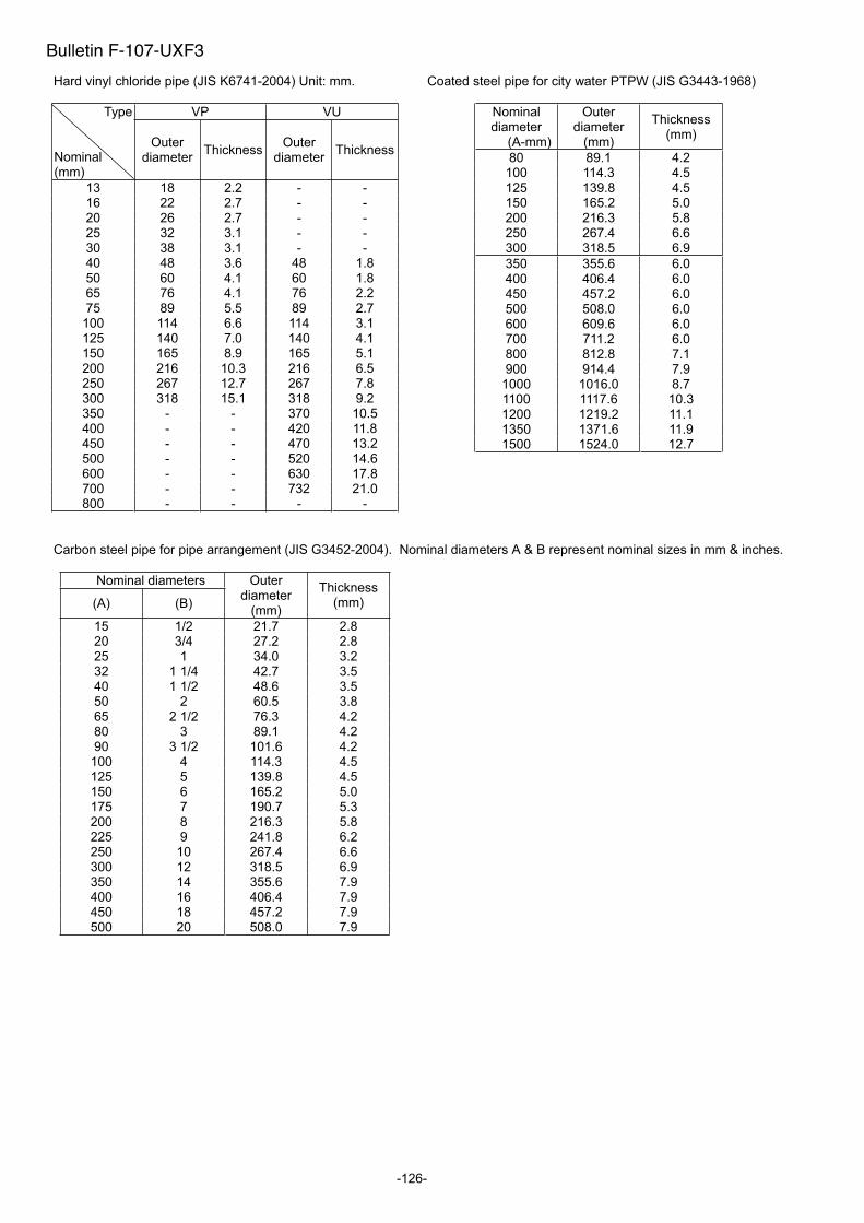
-126-
Hard vinyl chloride pipe (JIS K6741-2004) Unit: mm.
VP VU Type
Nominal (mm)
Outerdiameter
ThicknessOuter
diameter Thickness
13 18 2.2 - - 16 22 2.7 - - 20 26 2.7 - - 25 32 3.1 - - 30 38 3.1 - - 40 48 3.6 48 1.8 50 60 4.1 60 1.8 65 76 4.1 76 2.2 75 89 5.5 89 2.7
100 114 6.6 114 3.1 125 140 7.0 140 4.1 150 165 8.9 165 5.1 200 216 10.3 216 6.5 250 267 12.7 267 7.8 300 318 15.1 318 9.2 350 - - 370 10.5 400 - - 420 11.8 450 - - 470 13.2 500 - - 520 14.6 600 - - 630 17.8 700 - - 732 21.0 800 - - - -
Carbon steel pipe for pipe arrangement (JIS G3452-2004). Nominal diameters A & B represent nominal sizes in mm & inches.
Nominal diameters
(A) (B)
Outerdiameter
(mm)
Thickness(mm)
15 1/2 21.7 2.8 20 3/4 27.2 2.8 25 1 34.0 3.2 32 1 1/4 42.7 3.5 40 1 1/2 48.6 3.5 50 2 60.5 3.8 65 2 1/2 76.3 4.2 80 3 89.1 4.2 90 3 1/2 101.6 4.2
100 4 114.3 4.5 125 5 139.8 4.5 150 6 165.2 5.0 175 7 190.7 5.3 200 8 216.3 5.8 225 9 241.8 6.2 250 10 267.4 6.6 300 12 318.5 6.9 350 14 355.6 7.9 400 16 406.4 7.9 450 18 457.2 7.9 500 20 508.0 7.9
Coated steel pipe for city water PTPW (JIS G3443-1968)
Nominal diameter
(A-mm)
Outerdiameter
(mm)
Thickness (mm)
80 89.1 4.2 100 114.3 4.5 125 139.8 4.5 150 165.2 5.0 200 216.3 5.8 250 267.4 6.6 300 318.5 6.9
350 355.6 6.0 400 406.4 6.0 450 457.2 6.0 500 508.0 6.0 600 609.6 6.0 700 711.2 6.0 800 812.8 7.1 900 914.4 7.9
1000 1016.0 8.7 1100 1117.6 10.3 1200 1219.2 11.1 1350 1371.6 11.9 1500 1524.0 12.7
Bulletin F-107-UXF3
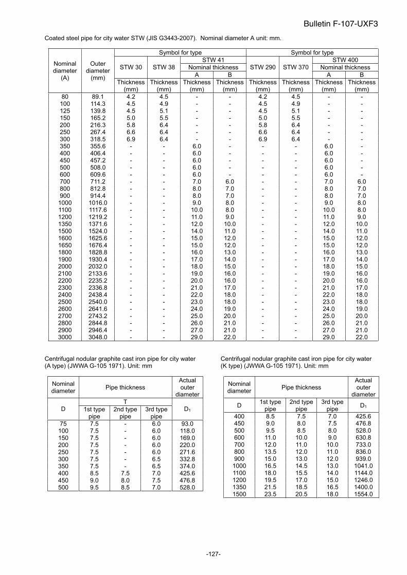
-127-
Coated steel pipe for city water STW (JIS G3443-2007). Nominal diameter A unit: mm.
Symbol for type Symbol for type
STW 41 STW 400
Nominal thickness Nominal thickness STW 30 STW 38
A B
STW 290 STW 370
A B
Nominal diameter
(A)
Outerdiameter
(mm)Thickness
(mm)Thickness
(mm)Thickness
(mm)Thickness
(mm)Thickness
(mm)Thickness
(mm)Thickness
(mm)Thickness
(mm)
80 89.1 4.2 4.5 - - 4.2 4.5 - - 100 114.3 4.5 4.9 - - 4.5 4.9 - - 125 139.8 4.5 5.1 - - 4.5 5.1 - - 150 165.2 5.0 5.5 - - 5.0 5.5 - - 200 216.3 5.8 6.4 - - 5.8 6.4 - - 250 267.4 6.6 6.4 - - 6.6 6.4 - - 300 318.5 6.9 6.4 - - 6.9 6.4 - - 350 355.6 - - 6.0 - - - 6.0 - 400 406.4 - - 6.0 - - - 6.0 - 450 457.2 - - 6.0 - - - 6.0 - 500 508.0 - - 6.0 - - - 6.0 - 600 609.6 - - 6.0 - - - 6.0 - 700 711.2 - - 7.0 6.0 - - 7.0 6.0 800 812.8 - - 8.0 7.0 - - 8.0 7.0 900 914.4 - - 8.0 7.0 - - 8.0 7.0
1000 1016.0 - - 9.0 8.0 - - 9.0 8.0 1100 1117.6 - - 10.0 8.0 - - 10.0 8.0 1200 1219.2 - - 11.0 9.0 - - 11.0 9.0 1350 1371.6 - - 12.0 10.0 - - 12.0 10.0 1500 1524.0 - - 14.0 11.0 - - 14.0 11.0 1600 1625.6 - - 15.0 12.0 - - 15.0 12.0 1650 1676.4 - - 15.0 12.0 - - 15.0 12.0 1800 1828.8 - - 16.0 13.0 - - 16.0 13.0 1900 1930.4 - - 17.0 14.0 - - 17.0 14.0 2000 2032.0 - - 18.0 15.0 - - 18.0 15.0 2100 2133.6 - - 19.0 16.0 - - 19.0 16.0 2200 2235.2 - - 20.0 16.0 - - 20.0 16.0 2300 2336.8 - - 21.0 17.0 - - 21.0 17.0 2400 2438.4 - - 22.0 18.0 - - 22.0 18.0 2500 2540.0 - - 23.0 18.0 - - 23.0 18.0 2600 2641.6 - - 24.0 19.0 - - 24.0 19.0 2700 2743.2 - - 25.0 20.0 - - 25.0 20.0 2800 2844.8 - - 26.0 21.0 - - 26.0 21.0 2900 2946.4 - - 27.0 21.0 - - 27.0 21.0 3000 3048.0 - - 29.0 22.0 - - 29.0 22.0
Centrifugal nodular graphite cast iron pipe for city water (A type) (JWWA G-105 1971). Unit: mm
Nominal diameter
Pipe thickness Actualouter
diameter
TD 1st type
pipe 2nd type
pipe 3rd type
pipe
D1
75 7.5 - 6.0 93.0 100 7.5 - 6.0 118.0 150 7.5 - 6.0 169.0 200 7.5 - 6.0 220.0 250 7.5 - 6.0 271.6 300 7.5 - 6.5 332.8 350 7.5 - 6.5 374.0 400 8.5 7.5 7.0 425.6 450 9.0 8.0 7.5 476.8 500 9.5 8.5 7.0 528.0
Centrifugal nodular graphite cast iron pipe for city water (K type) (JWWA G-105 1971). Unit: mm
Nominal diameter
Pipe thickness Actualouter
diameter
D1st type
pipe 2nd type
pipe 3rd type
pipe D1
400 8.5 7.5 7.0 425.6 450 9.0 8.0 7.5 476.8 500 9.5 8.5 8.0 528.0 600 11.0 10.0 9.0 630.8 700 12.0 11.0 10.0 733.0 800 13.5 12.0 11.0 836.0 900 15.0 13.0 12.0 939.0
1000 16.5 14.5 13.0 1041.01100 18.0 15.5 14.0 1144.01200 19.5 17.0 15.0 1246.01350 21.5 18.5 16.5 1400.01500 23.5 20.5 18.0 1554.0
Bulletin F-107-UXF3
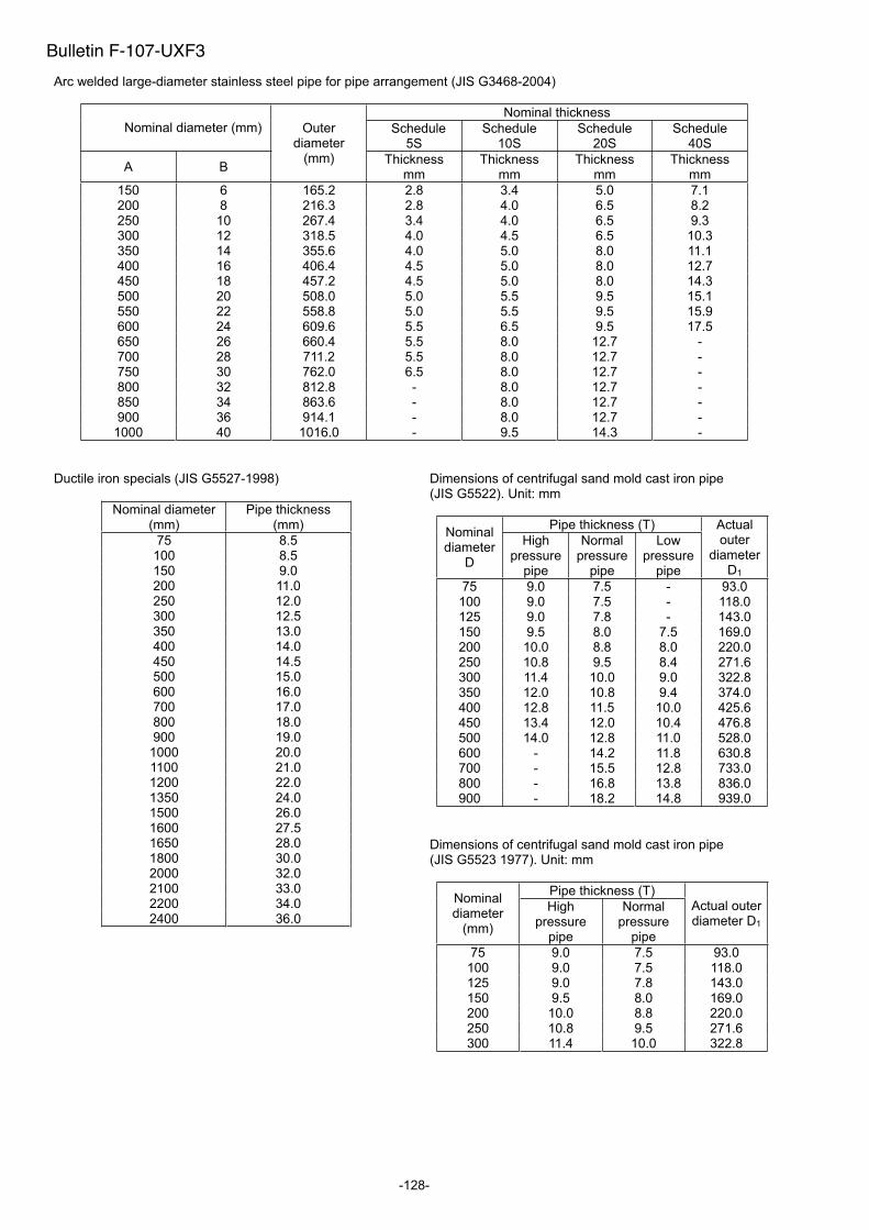
-128-
Arc welded large-diameter stainless steel pipe for pipe arrangement (JIS G3468-2004)
Nominal thickness Nominal diameter (mm) Schedule
5SSchedule
10SSchedule
20SSchedule
40S
A B
Outerdiameter
(mm) Thickness mm
Thickness mm
Thickness mm
Thickness mm
150 6 165.2 2.8 3.4 5.0 7.1 200 8 216.3 2.8 4.0 6.5 8.2 250 10 267.4 3.4 4.0 6.5 9.3 300 12 318.5 4.0 4.5 6.5 10.3 350 14 355.6 4.0 5.0 8.0 11.1 400 16 406.4 4.5 5.0 8.0 12.7 450 18 457.2 4.5 5.0 8.0 14.3 500 20 508.0 5.0 5.5 9.5 15.1 550 22 558.8 5.0 5.5 9.5 15.9 600 24 609.6 5.5 6.5 9.5 17.5 650 26 660.4 5.5 8.0 12.7 - 700 28 711.2 5.5 8.0 12.7 - 750 30 762.0 6.5 8.0 12.7 - 800 32 812.8 - 8.0 12.7 - 850 34 863.6 - 8.0 12.7 - 900 36 914.1 - 8.0 12.7 -
1000 40 1016.0 - 9.5 14.3 -
Ductile iron specials (JIS G5527-1998)
Nominal diameter (mm)
Pipe thickness (mm)
75 8.5 100 8.5 150 9.0 200 11.0 250 12.0 300 12.5 350 13.0 400 14.0 450 14.5 500 15.0 600 16.0 700 17.0 800 18.0 900 19.0
1000 20.0 1100 21.0 1200 22.0 1350 24.0 1500 26.0 1600 27.5 1650 28.0 1800 30.0 2000 32.0 2100 33.0 2200 34.0 2400 36.0
Dimensions of centrifugal sand mold cast iron pipe (JIS G5522). Unit: mm
Pipe thickness (T) Nominal diameter
D
Highpressure
pipe
Normalpressure
pipe
Low pressure
pipe
Actualouter
diameter D1
75 9.0 7.5 - 93.0 100 9.0 7.5 - 118.0 125 9.0 7.8 - 143.0 150 9.5 8.0 7.5 169.0 200 10.0 8.8 8.0 220.0 250 10.8 9.5 8.4 271.6 300 11.4 10.0 9.0 322.8 350 12.0 10.8 9.4 374.0 400 12.8 11.5 10.0 425.6 450 13.4 12.0 10.4 476.8 500 14.0 12.8 11.0 528.0 600 - 14.2 11.8 630.8 700 - 15.5 12.8 733.0 800 - 16.8 13.8 836.0 900 - 18.2 14.8 939.0
Dimensions of centrifugal sand mold cast iron pipe (JIS G5523 1977). Unit: mm
Pipe thickness (T) Nominal diameter
(mm)
Highpressure
pipe
Normalpressure
pipe
Actual outer diameter D1
75 9.0 7.5 93.0 100 9.0 7.5 118.0 125 9.0 7.8 143.0 150 9.5 8.0 169.0 200 10.0 8.8 220.0 250 10.8 9.5 271.6 300 11.4 10.0 322.8
Bulletin F-107-UXF3

-129-
Cast iron pipe for waste water (JIS G5525-1975). Unit:mm
Pipethickness
Actualinternal
diameter
Actualouter
diameter Nominal diameter
T D1 D2
50 6.0 50 62 65 6.0 65 77 75 6.0 75 87
100 6.0 100 112 125 6.0 125 137 150 6.0 150 162 200 7.0 200 214
Hard vinyl chloride pipe - city water (JIS K6742-1975) Unit:mm
Nominal diameter
Outerdiameter
Thickness
13 18 2.5 16 22 20 26 3.0 25 32 3.5 30 38 3.5 40 48 4.0 50 60 4.5 75 89 5.9
100 114 7.1 150 165 9.6
Arc welded carbon steel pipe STPY (JIS G3457-2005) Unit: kg/m
Nominal diameter
(A) (B)
Thickness (mm)
Outerdiameter (mm)
6.0 6.4 7.1 7.9 8.7 9.5 10.3 11.1 11.9 12.7 13.1 15.1 15.9
350 14 355.6 51.7 55.1 61.0 67.7 400 16 406.4 59.2 63.1 69.9 77.6 450 18 457.2 66.8 71.1 78.8 87.5 500 20 508.0 74.3 79.2 87.7 97.4 107 117 550 22 558.8 81.8 87.2 96.6 107 118 129 139 150 160 171 600 24 609.6 89.3 95.2 105 117 129 141 152 164 175 187 650 26 660.4 96.8 103 114 127 140 152 165 178 190 203 700 28 711.2 104 111 123 137 151 164 178 192 205 219 750 30 762.0 119 132 147 162 176 191 206 220 235 800 32 812.8 127 141 157 173 188 204 219 235 251 258 297 312850 34 863.6 167 183 200 217 233 250 266 275 315 332900 36 914.4 177 194 212 230 247 265 282 291 335 352
1000 40 1016.0 196 216 236 255 275 295 314 324 373 3921100 44 1117.6 260 281 303 324 346 357 411 4321200 48 1219.2 283 307 331 354 378 390 448 4721350 54 1371.6 399 426 439 505 5321500 60 1524.0 444 473 488 562 5911600 64 1625.6 521 600 6311800 72 1828.8 587 675 7112000 80 2032.0 751 791
Stainless steel sanitary pipe (JIS G3447-2004)
Nominal Outer
diameter (mm)
Thickness (mm)
Internaldiameter
(mm)
1.0S 25.4 1.2 23.0
1.25S 31.8 1.2 29.4
1.5S 38.1 1.2 35.7
2.0S 50.8 1.5 47.8
2.5S 63.5 2.0 59.5
3.0S 76.3 2.0 72.3
3.5S 89.1 2.0 85.1
4.0S 101.6 2.0 97.6
4.5S 114.3 3.0 108.3
5.5S 139.8 3.0 133.8
6.5S 165.2 3.0 159.2
Bulletin F-107-UXF3
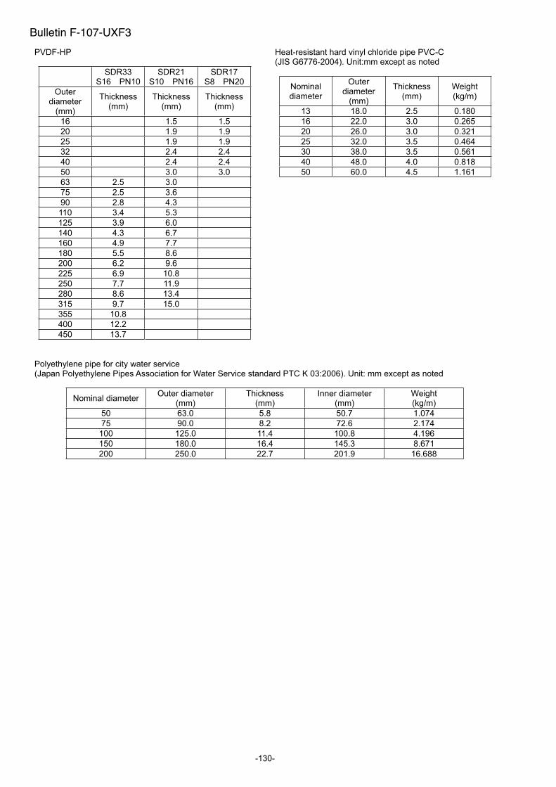
-130-
PVDF-HP
SDR33 S16 PN10
SDR21 S10 PN16
SDR17 S8 PN20
Outerdiameter
(mm)
Thickness (mm)
Thickness (mm)
Thickness (mm)
16 1.5 1.5
20 1.9 1.9
25 1.9 1.9
32 2.4 2.4
40 2.4 2.4
50 3.0 3.0
63 2.5 3.0
75 2.5 3.6
90 2.8 4.3
110 3.4 5.3
125 3.9 6.0
140 4.3 6.7
160 4.9 7.7
180 5.5 8.6
200 6.2 9.6
225 6.9 10.8
250 7.7 11.9
280 8.6 13.4
315 9.7 15.0
355 10.8
400 12.2
450 13.7
Heat-resistant hard vinyl chloride pipe PVC-C (JIS G6776-2004). Unit:mm except as noted
Nominal diameter
Outerdiameter
(mm)
Thickness (mm)
Weight (kg/m)
13 18.0 2.5 0.180
16 22.0 3.0 0.265
20 26.0 3.0 0.321
25 32.0 3.5 0.464
30 38.0 3.5 0.561
40 48.0 4.0 0.818
50 60.0 4.5 1.161
Polyethylene pipe for city water service (Japan Polyethylene Pipes Association for Water Service standard PTC K 03:2006). Unit: mm except as noted
Nominal diameter Outer diameter
(mm)Thickness
(mm)Inner diameter
(mm)Weight (kg/m)
50 63.0 5.8 50.7 1.074
75 90.0 8.2 72.6 2.174
100 125.0 11.4 100.8 4.196
150 180.0 16.4 145.3 8.671
200 250.0 22.7 201.9 16.688
Bulletin F-107-UXF3

-131-
(a) Velocity of sound subject to change of temperature of water (0 to 100 C)
T °C V m/s T °C V m/s T °C V m/s T °C V m/s
0 1402.74 1 1407.71 26 1499.64 51 1543.93 76 1555.40 2 1412.57 27 1502.20 52 1544.95 77 1555.31 3 1417.32 28 1504.68 53 1545.92 78 1555.18 4 1421.98 29 1507.10 54 1546.83 79 1555.02 5 1426.50 30 1509.44 55 1547.70 80 1554.81
6 1430.92 31 1511.71 56 1548.51 81 1554.57 7 1435.24 32 1513.91 57 1549.28 82 1554.30 8 1439.46 33 1516.05 58 1550.00 83 1553.98 9 1443.58 34 1518.12 59 1550.68 84 1553.63 10 1447.59 35 1520.12 60 1551.30 85 1553.25
11 1451.51 36 1522.06 61 1551.88 86 1552.82 12 1455.34 37 1523.93 62 1552.42 87 1552.37 13 1459.07 38 1525.74 63 1552.91 88 1551.88 14 1462.70 39 1527.49 64 1553.35 89 1551.35 15 1466.25 40 1529.18 65 1553.76 90 1550.79
16 1469.70 41 1530.80 66 1554.11 91 1550.20 17 1473.07 42 1532.37 67 1554.43 92 1549.58 18 1476.35 43 1533.88 68 1554.70 93 1548.92 19 1479.55 44 1535.33 69 1554.93 94 1548.23 20 1482.66 45 1536.72 70 1555.12 95 1547.50
21 1485.69 46 1538.06 71 1555.27 96 1546.75 22 1488.63 47 1539.34 72 1555.37 97 1545.96 23 1491.50 48 1540.57 73 1555.44 98 1545.14 24 1494.29 49 1541.74 74 1555.47 99 1544.29 25 1497.00 50 1542.87 75 1555.45 100 1543.41
Note) T: Temperature, V: Velocity
(b) Sound velocity and density of various liquids
Name of liquid T °C g/cm3
V m/s
Acetone 20 0.7905 1190Aniline 20 1.0216 1659Alcohol 20 0.7893 1168Ether 20 0.7135 1006Ethylene glycol 20 1.1131 1666n-octane 20 0.7021 1192o-xylol 20 0.871 1360Chloroform 20 1.4870 1001Chlorobenzene 20 1.1042 1289Glycerin 20 1.2613 1923Acetic acid 20 1.0495 1159Methyl acetate 20 0.928 1181Ethyl acetate 20 0.900 1164Cyclohexane 20 0.779 1284Dioxane 20 1.033 1389Heavy water 20 1.1053 1388Carbon tetrachloride 20 1.5942 938 Mercury 20 13.5955 1451Nitrobenzene 20 1.207 1473Carbon bisulfide 20 1.2634 1158Chloroform 20 2.8904 931 n-propyl alcohol 20 0.8045 1225n-pentane 20 0.6260 1032n-hexane 20 0.654 1083
Light oil 25 0.81 1324Transformer oil 32.5 0.859 1425Spindle oil 32 0.905 1342Petroleum 34 0.825 1295Gasoline 34 0.803 1250
Water 13.5 1. 1460Sea water (salinity: 3.5%) 16 1. 1510
Note) T: Temperature, : Density, V: Velocity
(c) Sound velocity of pipe material
Material V m/s
Iron 3230 Steel 3206 Ductile cast iron 3000 Cast iron 2460 Stainless steel 3206 Copper 2260 Lead 2170 Aluminium 3080 Brass 2050 Hi vinyl chloride 2640 Acrylic 2644 FRP 2505
Mortar 2500 Tar epoxy 2505 Polyethylene 1900 TFE
Note) V: Velocity
Bulletin F-107-UXF3
1240
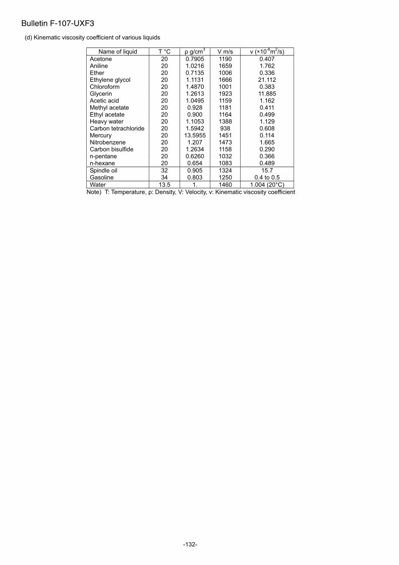
-132-
(d) Kinematic viscosity coefficient of various liquids
Name of liquid T °C g/cm3
V m/s (×10-6
m2/s)
Acetone 20 0.7905 1190 0.407 Aniline 20 1.0216 1659 1.762 Ether 20 0.7135 1006 0.336 Ethylene glycol 20 1.1131 1666 21.112 Chloroform 20 1.4870 1001 0.383 Glycerin 20 1.2613 1923 11.885 Acetic acid 20 1.0495 1159 1.162 Methyl acetate 20 0.928 1181 0.411 Ethyl acetate 20 0.900 1164 0.499 Heavy water 20 1.1053 1388 1.129 Carbon tetrachloride 20 1.5942 938 0.608 Mercury 20 13.5955 1451 0.114 Nitrobenzene 20 1.207 1473 1.665 Carbon bisulfide 20 1.2634 1158 0.290 n-pentane 20 0.6260 1032 0.366 n-hexane 20 0.654 1083 0.489
Spindle oil 32 0.905 1324 15.7 Gasoline 34 0.803 1250 0.4 to 0.5
Water 13.5 1. 1460 1.004 (20°C)
Note) T: Temperature, : Density, V: Velocity, : Kinematic viscosity coefficient
Bulletin F-107-UXF3

Corporate Headquarters102 Indiana Highway 212P.O. Box 373Michigan City, IN 46361 U.S.A.
Telephone: 219/879-8000Fax: 219/872-9057
www.dwyer-inst.com
Dwyer Instruments, Inc.
BULLETIN F-107-UXF3
TN1UXF3Ga-E