uhf trunked radios if43gt/gs if44gt/gs - icom · vo ce scrambler .....25 dtmf operat on ... (funct...
TRANSCRIPT

INSTRUCTION MANUAL
iF43GT/GSUHF TRUNKED RADIOS
iF44GT/GS

�
R CAUTION! NEVER hold the transce�ver so that the antenna �s very close to, or touch�ng exposed parts of the body, espec�ally the face or eyes, wh�le transm�tt�ng. The transce�ver w�ll perform best �f the m�crophone �s 5 to 10 cm away from the l�ps and the transce�ver �s vert�cal.
R CAUTION! NEVER operate the transce�ver w�th a headset or other aud�o accessor�es at h�gh volume levels.
R CAUTION! NEVER short the term�nals of the bat-tery pack.
DO NOT push PTT when not actually des�r�ng to transm�t.
DO NOT use or place the transce�ver �n d�rect sunl�ght or �n areas w�th temperatures below –25°C or above +55°C.
The bas�c operat�ons, transm�ss�on and recept�on of the transce�ver are guaranteed w�th�n the spec�f�ed operat�ng temperature range. However, the LCD d�splay may not be operate correctly, or show an �nd�cat�on �n the case of long hours of operat�on, or after be�ng placed �n extremely cold areas.
PRECAUTIONSIMPORTANT
READ ALL INSTRUCTIONS carefully and com-pletely before us�ng the transce�ver.
SAVE THIS INSTRUCTION MANUAL — Th�s �nstruct�on manual conta�ns �mportant operat�ng �nstruct�ons for the IC-F43GT/GS, F44GT/GS UHF TRUNKED RADIOS.
EXPLICIT DEFINITIONS
WORD DEFINITION
RDANGERPersonal death, ser�ous �njury or an explos�on may occur.
RWARNINGPersonal �njury, f�re hazard or electr�c shock may occur.
CAUTION Equ�pment damage may occur.
NOTEIf d�sregarded, �nconven�ence only. No r�sk of personal �njury, fire or electr�c shock.
Icom, Icom Inc. and the Icom logo are reg�stered trademarks of Icom Incor-porated (Japan) �n the Un�ted States, the Un�ted K�ngdom, Germany, France, Spa�n, Russ�a and/or other countr�es.

PRECAUTIONS
DO NOT mod�fy the transce�ver for any reason.
KEEP the transce�ver from the heavy ra�n, and Never �m-merse �t �n water. The transce�ver construct�on �s water re-sistant, not waterproof.The use of non-Icom battery packs/chargers may �mpa�r transce�ver performance and �nval�date the warranty.
Icom opt�onal equ�pment �s des�gned for opt�mal perfor-mance when used w�th th�s transce�ver. We are not respon-s�ble for the transce�ver be�ng damaged or any acc�dent caused when us�ng non-Icom opt�onal equ�pment.
��

���
TABLE OF CONTENTSIMPORTANT .......................................................................... �EXPLICIT DEFINITIONS ....................................................... �PRECAUTIONS ..................................................................... �TABLE OF CONTENTS ....................................................... ���
1 ACCESSORIES ...........................................................1–3 ■ Suppl�ed accessor�es ...................................................1 ■ Accessory attachments ................................................1
2 PANEL DESCRIPTION ................................................4–6 ■ Front panel ...................................................................4 ■ Funct�on d�splay ...........................................................6
3 BASIC OPERATION ..................................................7–20 ■ General.........................................................................7 ■ Call�ng ..........................................................................8 ■ Call�ng w�th the keypad (10-key vers�on only) ............12 ■ Spec�al call w�th the keypad .......................................17 ■ Rece�v�ng a call ..........................................................17
4 DISPLAYING MESSAGES ............................................21
5 OTHER FUNCTIONS ...............................................22–25 ■ PTT qu�ck call .............................................................22 ■ Call back funct�on .......................................................22 ■ Call�ng stat�on ID �nd�cat�on for group call ..................23 ■ System lock funct�on ..................................................24 ■ Call code memory ......................................................24 ■ Automat�c transm�t output power select�on .................24 ■ Power ON secur�ty......................................................24
■ Vo�ce scrambler ..........................................................25 ■ DTMF operat�on .........................................................25 ■ Compander funct�on ...................................................25
6 USER SET MENU ...................................................26–27 ■ User set menu ............................................................26
7 TALK AROUND .............................................................28
8 PROGRAMMABLE FUNCTIONS............................29–30 ■ Programmable funct�on keys ......................................29
9 OPTIONAL UNIT INSTALLATION ................................31 ■ UT-109 and UT-110 �nstallat�on ..................................31
10 BATTERY CHARGING ............................................32–36 ■ Caut�on .......................................................................32 ■ Opt�onal battery chargers ...........................................34
11 OPTIONAL BATTERY CASE ........................................37 ■ Battery case (BP-240) ................................................37
12 OPTIONAL SWIVEL BELT CLIP ............................38–39 ■ MB-93 contents ..........................................................38 ■ Attach�ng ....................................................................38 ■ Detach�ng ...................................................................39
13 OPTIONS .................................................................40–41
14 DOC ...............................................................................42

■ Supplied accessoriesThe follow�ng accessor�es are suppl�ed: Qty.q Flex�ble antenna ...............................................................1w Battery pack .....................................................................1e Belt cl�p ............................................................................1r Un�t cover (double-s�ded tape)* ........................................1t Jack cover (w�th screws) ............................................ 1 set*Use the un�t cover as a spare. Ask your dealer for deta�ls.
q w
r
e
t
■ Accessory attachmentsD Flexible antennaConnect the suppl�ed flex�ble an-tenna to the antenna connector.
CAUTION:• NEVER HOLD the antenna
when carry�ng the transce�ver.• Transm�tt�ng w�thout an antenna
may damage the transce�ver.
1
1ACCESSORIES
12345678910111213141516

2
1 ACCESSORIES
D Battery packTo attach the battery pack:Sl�de the battery pack �n the d�rect�on of the arrow (q), then lock �t w�th the battery release button.• Sl�de the battery pack unt�l the battery release button makes a ‘cl�ck’
sound.
To release the battery pack:Push the battery release button �n the d�rect�on of the arrow (w) as shown below. The battery pack �s then released.
NEVER release or attach the battery pack when the trans-ce�ver �s wet or so�led. Th�s may result water or dust get-t�ng �nto the transce�ver/battery pack and may result �n the transce�ver be�ng damaged.
q
w
D Belt clipTo attach the belt clip:q Release the battery pack �f �t �s attached.w Sl�de the belt cl�p �n the d�rect�on of the arrow unt�l the belt
cl�p �s locked and makes a ‘cl�ck’ sound.
To detach the belt clip:q Release the battery pack �f �t �s attached.w P�nch the cl�p (q), and sl�de the belt cl�p �n the d�rect�on of
the arrow (w).
q
w
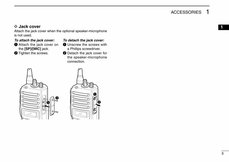
D Jack cover Attach the jack cover when the opt�onal speaker-m�crophone �s not used.
To attach the jack cover:q Attach the jack cover on
the [SP]/[MIC] jack.w T�ghten the screws.
To detach the jack cover:q Unscrew the screws w�th
a Ph�ll�ps screwdr�ver.w Detach the jack cover for
the speaker-m�crophone connect�on.
q
wq
w
3
1ACCESSORIES
12345678910111213141516

4
2 PANEL DESCRIPTION
■ Front panelq
w
e
r
t
u
10-keypad version
yi
o
!0
!1
!2
!3
Function display(p. 6)
q GROUP SELECTOR Rotate to select the pre-programmed group code chan-
nel.
w VOLUME CONTROL [VOL] Rotate to turn the power ON/OFF and adjusts the aud�o
level.
e EMERGENCY KEY [RED] ➥ Push and hold for 2 sec. to start the emergency call to
the spec�fied number (Emergency call; p. 15). ➥“EMRGENCY” �s d�splayed wh�le push�ng and hold�ng.
r [SP]/[MIC] JACK Connect the opt�onal speaker-m�crophone.
[SP]/[MIC] jack cover
NOTE: Attach the [SP]/[MIC] jack cover when the opt�onal speaker-m�crophone �s not used. (See p. 3 for deta�ls)
t MODE KEY [P2] (p. 28) Push to toggle between convent�onal and trunk�ng opera-
t�on modes.
y HIGH/LOW KEY [P3] Push to toggle the transm�t output power. • When automat�c power select�on �s enabled for trunk�ng mode
operat�on, the transm�t output power cannot be selected w�th th�s key.

u 10-KEYPAD (Depend�ng on vers�on) The keypad allows you to enter d�g�ts to: • Set TX codes • Set DTMF codes (dur�ng transm�t) • Input text message for SDM operat�on • Start up w�th the password
i DESPATCHER KEY [P0] (p. 10) ➥Push to d�splay despatcher call cond�t�ons. ➥Push aga�n to d�splay the status code, �f perm�tted. ➥Push aga�n to return to stand-by cond�t�on.
o CALL BACK KEY [P1] (p. 22) ➥ Push to d�splay the rece�ved call record (call back mem-
ory) that had not repl�ed. ➥Push aga�n to return to stand-by cond�t�on. ➥ Push and hold for 2.5 sec. to toggle the call back mode
ON and OFF. • When the call back mode �s set to ON, the rece�ved call �s
stored �nto record (log), and the call back message �s send back to the call�ng stat�on automat�cally.
!0 UP/DOWN KEYS ➥Push to select the call memory channel. ➥Push to select the call back memory channel. ➥Push to select the status channel. ➥ Push to select the operat�ng channel. (Convent�onal
mode operat�on only) ➥ Push to select the sett�ng value or cond�t�on dur�ng user
set mode.
➥ Push to erase the prev�ously entered d�g�t number (funct�ons as back space key) dur�ng d�al�ng number enter�ng from the keypad. (10-key vers�on only)
!1 PTT SWITCH [PTT] ➥ Push to mak�ng a call w�th the d�splayed d�al�ng num-
ber. ➥ When select�ng a traffic channel for commun�cat�on, or
convent�onal mode, push to transm�t. ➥ When an �nd�v�dual call �s rece�ved, push to reply the
call.
!2 CLEAR (SET MODE) KEY (pgs. 8, 26) ➥Push to fin�sh the commun�cat�on. ➥Push and hold to enter to the user set menu. ➥ Dur�ng some funct�on operat�on, push to return to stand-
by cond�t�on.
!3 ANTENNA CONNECTOR Connects the suppl�ed antenna.
Des�red funct�ons can be programmed �nto the [P0] to [P3], [Red], [Clear], [Up] and [Down] keys �ndependently by your dealer. (p. 29)
5
2PANEL DESCRIPTION
12345678910111213141516

6
2 PANEL DESCRIPTION
■ Function displayq !1!0oiuytrew
!2
!3
!4
q TRANSMIT INDICATOR Appears wh�le transm�tt�ng.
w BUSY INDICATOR Appears wh�le the channel �s busy.
e OVER-FLOW INDICATOR Appears when the rece�ved SDM �nclud�ng more than 9
characters �s d�splayed.
r SIGNAL STRENGTH INDICATOR Appears when rece�v�ng a s�gnal and shows the s�gnal
strength levels �n 4-steps. • No bars appear and “ ” bl�nks when the transce�ver �s �n out-of
serv�ce area. For stable commun�cat�ons, the transce�ver should be �n the area that the S-meter �nd�cator shows the full scales (3 bars) �nd�cat�on.
t LOW POWER INDICATOR Appears when low output power �s selected. • When the battery power decreases to a spec�fied level, low
power �s selected automat�cally.
y AUDIBLE INDICATOR Appears when the vo�ce commun�cat�on can be per-
formed.
u COMPANDER INDICATOR Appears when the compander funct�on �s act�vated. • The compander funct�on �mproves commun�cat�ng aud�o qual�ty.
i SCRAMBLER INDICATOR Appears when the vo�ce scrambler funct�on �s act�vated.
o CALL BACK INDICATOR ➥Bl�nks when an �nd�v�dual call �s rece�ved. ➥ Appears when �nd�v�dual calls that the call back opera-
t�on has not been performed are ava�lable. ➥D�sappears when repl�es to all �nd�v�dual calls.
!0 PRIMARY NETWORK INDICATOR Appears when the transce�ver �s �n the pr�mary network
serv�ce area.
!1 KEY LOCK INDICATOR Appears when the key lock funct�on �s turned ON.
!2 BATTERY INDICATOR Appears or bl�nks when the battery power decreases to a
spec�fied level.
!3 ALPHANUMERIC DISPLAY Shows d�al�ng number and rece�ved message, etc.
!4 SYSTEM LOCK INDICATOR Appears when the system lock funct�on �s �n use.

■ GeneralRotate [VOL] to turn the transce�ver power ON.Beeps sound, and the follow�ng contents w�ll be d�splayed �n sequence.
• Opening text• Prefix code (3-d�g�t)/Fleet code (4-d�g�t)• Individual code (2 or 3-d�g�t)• Memory group code (or text name) - The selected memory group code (selected by [Group se-
lector]) and “ ” are d�splayed when the transce�ver �s �n the trunk�ng serv�ce area, and the des�red call can be made. (The text name �s d�splayed �f programmed �nstead of the group code.)
- “ ” bl�nks when the transce�ver �s �n out-of-serv�ce area, or the system �s fall down. The transce�ver search�ng for an operatable system base �n th�s case.
- “ ” appears when the control s�gnal from the base stat�on that the system ID (AAD number) �s reg�stered �n pr�mary network.
e.g.: When the Prefix code �s ‘201,’ Fleet code �s ‘2001,’ Ind�-v�dual code �s ‘300’ and Group code �s ‘90,’ “201/2001”, “300” and “90” are d�splayed �n sequence after turn�ng the transce�ver ON.
(Open�ng text)
Open�ng text �s d�splayed.
⇓201/2001
Prefix code/Fleet code �s d�s-played.
⇓300
Ind�v�dual code �s d�splayed.
⇓90
A group code �s d�splayed when no text name �s pro-grammed.
7
3BASIC OPERATION
12345678910111213141516

8
3 BASIC OPERATION
■ CallingThe follow�ng call operat�ons can be performed us�ng the pre-programmed d�al�ng number.
D Group callSelect the des�red group code that �s stored �n the memory us�ng [Group selector] or [Up]/[Down].Up to 16 group codes w�th [Group selector], up to 40 group codes w�th [Up]/[Down] can be selected.
q Rotate [Group selector] or [Up]/[Down] to select the de-s�red group code.
GROUP 1
The pre-programmed text name �s d�splayed.
90
When no text name �s pro-grammed, a group code �s d�splayed.
w Push [PTT] or [Call Set Up] to make a group call. • “CALLING” �s d�splayed and the call�ng beeps sound.
CALLING
e When the call �s succeeded, “CONNECT” and “ ” appear, and commun�cat�on can be made.
• The commun�cat�on t�mer starts count down at the same t�me. (When no transm�ss�on t�me l�m�t �s set, the t�mer counts up.)
CONNECT
TIM 0 56
r The warn�ng beeps sound 10 sec. before the commun�ca-t�on t�mer �s act�vated.
• The commun�cat�on �s d�sconnected automat�cally when the commun�cat�on t�mer �s act�vated.
t Push [Clear] to d�sconnect the commun�cat�on manually. • Push�ng [M] and [#] �n sequence also d�sconnect the commun�-
cat�on. (10-key vers�on only)
CLR DOWN

D Individual callSelect the des�red �nd�v�dual code w�th [Up]/[Down].
q Push [Up]/[Down] to select the des�red �nd�v�dual code.
PERSON 1
The pre-programmed text name �s d�splayed.
20 302
When no text name �s pro-grammed, the d�al�ng num-ber �s d�splayed.
w Push [PTT] or [Call Set Up] to make an �nd�v�dual call. • “CALLING” �s d�splayed and call�ng beeps sound.
CALLING
e When the call �s succeeded, “CONNECT” and “ ” appear, and commun�cat�on can be made.
• The commun�cat�on t�mer starts count down at the same t�me. (When no transm�ss�on t�me l�m�t �s set, the t�mer counts up.)
CONNECT
TIM 0 56
r The warn�ng beeps sound 10 sec. before the commun�ca-t�on t�mer �s act�vated.
• The commun�cat�on �s d�sconnected automat�cally when the commun�cat�on t�mer �s act�vated.
t Push [Clear] to d�sconnect the commun�cat�on manually. • Push�ng [M] and [#] �n sequence also d�sconnect the commun�-
cat�on. (10-key vers�on only)
CLR DOWN
9
3BASIC OPERATION
12345678910111213141516

10
3 BASIC OPERATION
D Despatcher callA status �s used for the despatcher call normally, however, the d�rect despatcher call can be made accord�ng to the sett�ng.
q Push [Despatcher] to select the despatcher call cond�t�on. • “DESPATCH” �s d�splayed.
DESPATCH
w Push [PTT] or [Call Set Up] to make the despatcher call. • When the d�rect despatcher call �s �nh�b�ted, the status message
“0 (call back request)” �s transm�tted, then returns to stand-by cond�t�on.
• “CALLING” �s d�splayed and the call�ng beeps sound.
CALLING
e When the call �s succeeded, “CONNECT” and “ ” appear, and commun�cat�on can be made.
• The commun�cat�on t�mer starts count down at the same t�me. (When no transm�ss�on t�me l�m�t �s set, the t�mer counts up.)
CONNECT
TIM 0 56
r The warn�ng beeps sound 10 sec. before the commun�ca-t�on t�mer �s act�vated.
• The commun�cat�on �s d�sconnected automat�cally when the commun�cat�on t�mer �s act�vated.
t Push [Clear] to d�sconnect the commun�cat�on manually. • Push�ng [M] and [#] �n sequence also d�sconnect the commun�-
cat�on. (10-key vers�on only)
CLR DOWN

D Status callA status message can be sent to the �nd�v�dual or despatcher stat�on.The status message cannot be sent to a group stat�ons.
• Individual status callq Push [Up]/[Down] to select the des�red �nd�v�dual code.
PERSON 1
w Push [Status] to enter the status message select�on mode.
e Push [Up]/[Down] to select the des�red status message from total of 32 messages (code 0 to 31.)
• The status code 0 and 31 are common message �n the system. Code 0 : Call Back Request Code 31 : Call Cancel
STATUS 1
r Push [PTT] or [Call Set Up] to transm�t the selected status message to the selected stat�on.
• “CALLING” �s d�splayed.
CALLING
t When the status call �s succeeded, “OK” �s d�splayed.
OK
• Despatcher status callq Push [Despatcher] to select the despatcher call cond�t�on. • “DESPATCH” �s d�splayed.
DESPATCH
w Push [Despatcher] aga�n to enter a status message selec-t�on mode.
STATUS 1
e Push [Up]/[Down] to select the des�red status message. • Ava�lable number of messages and code numbers are the same
as the Ind�v�dual status call as at left.r Push [PTT] or [Call Set Up] to transm�t the selected status
message to the despatcher. • “CALLING” �s d�splayed.
CALLING
t When the status call �s succeeded, “OK” �s d�splayed.
OK
11
3BASIC OPERATION
12345678910111213141516

12
3 BASIC OPERATION
Several call operat�on can be performed w�th the follow�ng d�al�ng number �nput (v�a the keypad) and [#].
NOTE: [PTT] or [Call Set Up] can also be used �nstead of [#].
D Individual callTo the station that has the same prefix and fleetEnter the des�red �nd�v�dual code v�a the keypad, then push [#] to make the �nd�v�dual call.e.g.: When the stat�on ‘201 2001 200’ calls the stat�on ‘201
2001 300’; ➥Push [3], [0], [0] and [#] �n sequence.
To the station that has the same prefix, but different fleetEnter the des�red fleet and �nd�v�dual codes v�a the keypad, then push [#] to make the �nd�v�dual call.e.g.: When the stat�on ‘201 2001 200’ calls the stat�on ‘201
2010 300’; ➥Push [2], [0], [1], [0], [3], [0], [0] and [#] �n sequence.
To the station that has different prefixEnter the des�red prefix, fleet and �nd�v�dual codes v�a the keypad, then push [#] to make the �nd�v�dual call.e.g.: When the stat�on ‘201 2001 200’ calls the stat�on ‘211
2010 300’; ➥ Push [2], [1], [1], [2], [0], [1], [0], [3], [0], [0] and [#] �n
sequence.
D Group callTo the group that has the same prefix and fleetEnter the des�red group code v�a the keypad, then push [#] to make the group call.e.g.: When the stat�on �n the group ‘201 2001 200’ calls the
stat�on group ‘201 2001 900’; ➥Push [9], [0], [0] and [#] �n sequence.
To the group that has the same prefix, but different fleetEnter the des�red fleet and group codes v�a the keypad, then push [#] to make the group call.e.g.: When the stat�on �n the group ‘201 2001 200’ calls the
stat�on group ‘201 2010 900’; ➥Push [2], [0], [1], [0], [9], [0], [0] and [#] �n sequence.
To the group that has the different prefixEnter the des�red prefix, fleet and group codes v�a the key-pad, then push [#] to make the group call.e.g.: When the stat�on �n the group ‘201 2001 200’ calls the
stat�on group ‘211 2010 900’; ➥Push [2], [1], [1], [2], [0], [1], [0], [9], [0], [0] and [#] �n
sequence.
■ Calling with the keypad (10-key vers�on only)

D Status call➥Push [M], [0], [xx]*, [M], �nd�v�dual code and [#] �n sequence
to make a status call to the des�red stat�on.➥Push [M], [0], [xx]* and [#] �n sequence to make a status
call to the despatcher.➥Push [M], [0] and [#] �n sequence to make a Call Back Re-
quest status call to the despatcher➥ Push [#], [0] and [#] �n sequence to make a cancellat�on
of the above Call Back Request status call to the des-patcher.
➥Push [M], [0], [M], �nd�v�dual code and [#] �n sequence to make the Call Back Request status call to the �nd�v�dual code stat�on.
➥Push [#], [0], [M], �nd�v�dual code and [#] �n sequence to make the cancellat�on of the above Call Back Request sta-tus call to the �nd�v�dual code stat�on.
* xx �s a status code number from 00 to 31.
NOTE: The same manner as the �nd�v�dual call (p. 12) �s used when mak�ng an �nd�v�dual status call to the d�fferent prefix and/or fleet code.
D PSTN callPush [0], telephone number (1-d�g�t or more) and [#] to make a phone call through the publ�c telephone network.The system must be compat�ble to the PSTN.
D Enhanced group call• Conference callPush [M], [1], [M], group code and [#] �n sequence to make a conference call.All stat�ons �n the called group can be commun�cated w�th the conference call.
• Broadcast callPush [M], [1], [1], [M], and group code and [#] �n sequence to make a broadcast call.All stat�ons �n the called group can only l�sten to the an-nouncement from the call�ng stat�on.
NOTE: The same manner as the group call (p. 12) �s used when mak�ng a conference or broadcast call to the d�ffer-ent prefix and/or fleet code.
D SDM (Short Data Message) call➥Push [M], [2], [M], SDM memory number and [#] �n se-
quence to make an SDM call (up to 24-d�g�t; �nclud�ng M, 2 and M) to the prev�ously selected stat�on or group.
➥Push [M], [2], [M], SDM memory number, �nd�v�dual code and [#] �n sequence to make an SDM call (up to 24-d�g�t; �nclud-�ng M, 2, M and �nd�v�dual code) to the des�red stat�on.
NOTE: The same manner as the �nd�v�dual call (p. 12) �s used when mak�ng an �nd�v�dual SDM call to the d�fferent prefix and/or fleet code.
13
3BASIC OPERATION
12345678910111213141516

14
3 BASIC OPERATION
D Data callPush [M], [3], [1], [M], �nd�v�dual or group code and [#] �n se-quence to make a data call to the des�red �nd�v�dual or group stat�on(s).A commun�cat�on channel �s automat�cally selected after the call, however, the m�crophone aud�o transm�ss�on and aud�o output are �nh�b�ted.• “ ” bl�nks dur�ng the data call �s performed.
NOTE: • External modem �s requ�red for the data call, however,
the transce�ver does not support an external modem. • The same manner as the �nd�v�dual or group call (p. 12)
�s used when mak�ng an �nd�v�dual or group data call to the d�fferent prefix and/or fleet code.
D Divert own call➥Push [M], [4], [1], [x]*, [M], �nd�v�dual code (to be transferred
to) and [#] �n sequence to transfer the call to the des�red stat�on.
➥Push [#], [4], [1], [x]*, [M] and [#] �n sequence to cancel the d�vert own call.
At the transferred stat�on, push [#], [4], [5], [x]* and [#] �n sequence to cancel the transferred sett�ng.
*x: Enter “1” for vo�ce, “0” for data and sk�p the d�g�t �nput for both vo�ce and data.
NOTE: The same manner as the �nd�v�dual call (p. 12) �s used when sett�ng the d�vert own call to the d�fferent prefix and/or fleet code.
D Divert 3rd party call➥Push [M], [4], [4], [x]*, �nd�v�dual code (B; transferr�ng sta-
t�on), �nd�v�dual code (A; transferred stat�on) and [#] �n se-quence to transfer the call from stat�on B to A.
➥Push [#], [4], [4], [x]*, [M], �nd�v�dual code (B; transferr�ng stat�on) and [#] �n sequence to cancel the transferr�ng.
*x: Enter “1” for vo�ce, “2” for data and sk�p the d�g�t �nput for both vo�ce and data.
NOTE: The same manner as the �nd�v�dual call (p. 12) �s used when sett�ng the d�vert 3rd party call to the d�ffer-ent prefix and/or fleet code.
D Cancellation of divert call➥ Push [#], [4], [1], [x]* and [#] �n sequence to cancel the
d�vert own call.➥ Push [#], [4], [4], [x]*, �nd�v�dual code (B; call transferr�ng
stat�on) and [#] �n sequence to cancel the d�vert 3rd party call.
➥ Push [#], [4], [5], [x]* and [#] �n sequence to cancel the call transformat�on from the other stat�on.
*x: Enter “1” for vo�ce, “0” for data and sk�p the d�g�t �nput for both vo�ce and data.
NOTE: The same manner as the �nd�v�dual call (p. 12) �s used when sett�ng the cancellat�on of d�vert call to the d�fferent prefix and/or fleet code.

D PABX callWhen mak�ng a PABX call, push [7] or [8] and phone number (5-d�g�t or more when start�ng w�th ‘7,’ 4-d�g�t or more when start�ng w�th ‘8’), then push [#].The system must be compat�ble to the PSTN.
D Priority callPush [M], [8], [M], �nd�v�dual or group code and [#] �n se-quence to make a pr�or�ty call.The pr�or�ty �s g�ven to the call by wa�t�ng for turn when the system �s �n busy.
NOTE: The same manner as the �nd�v�dual or group call (p. 12) �s used when sett�ng the pr�or�ty call to the d�fferent prefix and/or fleet code.
D Emergency callThe emergency call can be made even the system �s �n busy by mak�ng a clear channel �n force.
➥Push [M], [9], [M], �nd�v�dual or group code and [#] �n se-quence to make an emergency call.
➥ When push�ng [M], [9] and [#] �n sequence to make an emergency call to the despatcher.
NOTE: The same manner as the �nd�v�dual or group call (p. 12) call �s used when sett�ng the pr�or�ty call to the d�f-ferent prefix and/or fleet code.
D System Wide call• Priority Voice CallPush [M], [1], [9], [8], [1], and [#] �n sequence to make a pr�or-�ty vo�ce call.
• Emergency Voice CallPush [M], [1], [9], [8], [2], and [#] �n sequence to make an emergency vo�ce call.
• Standard Voice CallPush [M], [1], [9], [8], [7], and [#] �n sequence to make a stan-dard vo�ce call.
These calls as above call�ng all stat�ons they are �n stand by cond�t�on �n the system.
• Priority Data CallPush [M], [1], [9], [8], [3], and [#] �n sequence to make a pr�or-�ty data call.
• Emergency Data CallPush [M], [1], [9], [8], [4], and [#] �n sequence to make an emergency data call.
A commun�cat�on channel �s selected automat�cally after the data call, however, the m�crophone aud�o transm�ss�on and rece�ve aud�o em�ss�on are �nh�b�ted.• “ ” bl�nks dur�ng the data call �s performed.
NOTE: An external modem �s requ�red for the data opera-t�on, however, the transce�ver does not support an external modem.
15
3BASIC OPERATION
12345678910111213141516

16
3 BASIC OPERATION
D Include callThe �nclude call allows to make an extra call for jo�n�ng an-other stat�on for the commun�cat�on after move to a commu-n�cat�on channel.The �nclude call �s made when an �nd�v�dual or group code select�on us�ng a memory or keypad �s performed on the commun�cat�on channel.
D 5-digit routing code callThe 5-d�g�t rout�ng code call prov�des a shorten�ng a call�ng code �nput.When call�ng a stat�on that has a d�fferent prefix and/or fleet code, the 3-d�g�t prefix and 4-d�g�t fleet code are converted �nto 2 or 3-d�g�t code, therefore, enter�ng a total of 5-d�g�t code �nclud�ng an �nd�v�dual or group code.
• The conversion rangeCode w�th�n 200 to 299, 900 to 998, 20 to 29 and 90 to 99 can be converted, and set the des�red prefix and fleet code must be reg�stered �n advance.
e.g.: When the stat�on ‘200 2001 200’ calls the stat�on ‘211 2006 300’;
➥Reg�ster the both prefix ‘211’ and fleet ‘2006’ to “22” as the 5-d�g�t rout�ng code— Enter “22300” and push-�ng [#] to make a 5-d�g�t rout�ng code call.
D Call cancelPush [M] and [#] to cancel the call.The commun�cat�on �s d�sconnected, and the call �s can-celled.
D Cancelling the entered codeDur�ng code enter�ng from the keypad, push�ng [Up]/[Down] or [Backspace] to clear the prev�ously entered d�g�t code.The entered all d�g�t code can be cancelled by push�ng [Clear].
D Manual call replyWhen the call w�th “ALERTING” �nd�cat�on �s rece�ved, push [#] or [PTT] to reply the call manually (off-hook).
D End of the communicationPush [M] and [#], or push [Clear] to fin�sh (d�sconnect) the commun�cat�on (on-hook).

■ Special call with the keypadD Re-dialPush [#] tw�ce to re-call the prev�ously called �nd�v�dual or group stat�on(s).
D Short dialingPush one of [1] to [9] and [#], to make a call w�th the stored �nd�v�dual or group code �n the memory 1 to 9.
■ Receiving a callD Receiving an individual callq When an �nd�v�dual call �s rece�ved, call�ng r�ng sounds. • “ALERTING” and the call�ng stat�on code (or text name �f the
call�ng code �s memor�zed �n the memory) are d�splayed alter-nately.
⇔
• When the call from a telephone, “TEL” (PSTN) or “PABX” �s d�s-played.
w Push [PTT] or [#] to start the commun�cat�on. • The commun�cat�on t�mer �s d�splayed and starts count down.
(When no transm�ss�on t�me l�m�t �s set, the t�mer counts up.) • The channel number and the commun�cat�on t�mer are d�splayed
s�multaneously (�llustrated as at below r�ght) when the commun�-cat�on channel number �nd�cat�on �s set to ON. (p. 27)
e The warn�ng beeps sound 10 sec. before the commun�ca-t�on t�mer �s act�vated.
• The commun�cat�on �s d�sconnected automat�cally when the commun�cat�on t�mer �s act�vated.
r Push [Clear] to d�sconnect the commun�cat�on manually. • Push�ng [M] and [#] �n sequence also d�sconnect the commun�-
cat�on. (10-key vers�on only) • The transce�ver returns to stand-by cond�t�on.
17
3BASIC OPERATION
12345678910111213141516
ALERTING 302
TEL PABX
TIM 0 56 0020 0 56

18
3 BASIC OPERATION
• When not answering the callWhen not answer�ng call w�th [PTT], the call�ng stat�on code �s stored �nto call back memory. (max. 15 channels)• “ ” bl�nks when a call from the stat�on that the stat�on code
does not stored �n the call back memory, �s rece�ved.• “ ” appears when the call back memory that call back op-
erat�on has not been performed �s/are stored.
➥ Push [Call Back] then [Up]/[Down] to select the des�red call back memory, and then push [PTT] or [Call Set Up] to reply the call.
• The pre-programmed text name �s d�splayed �n case of the call-�ng code �s memor�zed �n the memory.
Q01 302
D Receiving an group callThe transce�ver wa�ts for a group call w�th the selected group code (that �s selected w�th [Group Selector] or [Up]/[Down]) or the pre-programmed group codes (stand-by group).The transce�ver wa�ts for a group call w�th the pre-pro-grammed stand-by group codes when an �nd�v�dual code �s d�splayed. The pre-programmed stand-by group code �s not d�splayed on the LCD.
q When a group call �s rece�ved, beeps sound and the trans-ce�ver turns the commun�cat�ng cond�t�on automat�cally.
• “GRP” and the call�ng stat�on code are d�splayed.
GRP 302
Rece�v�ng a group call w�th the selected group code.
GRP 1 302
Rece�v�ng a group call w�th the stand-by group code 1.

w Push and hold [PTT] to commun�cate w�th the call�ng sta-t�on.
• The commun�cat�on t�mer �s d�splayed and starts count down. (When no transm�ss�on t�me l�m�t �s set, the t�mer counts up.)
• The channel number and the commun�cat�on t�mer are d�splayed s�multaneously (�llustrated as at below r�ght) when the commun�-cat�on channel number �nd�cat�on �s set to ON. (p. 27)
e The warn�ng beeps sound 10 sec. before the commun�ca-t�on t�mer �s act�vated.
• The commun�cat�on �s d�sconnected automat�cally when the commun�cat�on t�mer �s act�vated.
r Push [Clear] to d�sconnect the commun�cat�on manually. • Push�ng [M] and [#] �n sequence also d�sconnect the commun�-
cat�on. (10-key vers�on only) • The transce�ver returns to stand-by cond�t�on.
D Receiving a status messageWhen a status call �s rece�ved, the transce�ver em�ts beeps, and the appropr�ate text message to the rece�ved status num-ber and the �nd�v�dual code of call�ng stat�on are d�splayed alternately.
⇔
• The d�splay �s cancelled and returns to the stand-by �nd�ca-t�on when [Clear] �s pushed.
• When the status 0 (call back request) �s rece�ved, the call�ng stat�on code �s stored �nto the call back memory and “ ” bl�nks. However, the status 31 (call back cancel) �s rece�ved, the call�ng stat�on code �s erased from the call back mem-ory.
D Receiving an SDM (Short Data Message)When an SDM �s rece�ved, beeps sound and the rece�ved message contents and the call�ng stat�on code are d�splayed alternately.
⇔
• “ ” appears when the message that conta�n�ng more than 9-d�g�t message �s rece�ved.
- Push [Down] to scroll the �nd�cat�on to d�splay the follow�ng message �n th�s case.
- Push [Up] to d�splay the prev�ous d�g�t message. - Push [Clear] to return to stand-by �nd�cat�on.
19
3BASIC OPERATION
12345678910111213141516
STATUS 1 302
TIM 0 56 0020 0 56
(Message) 302

20
3 BASIC OPERATION
D Receiving a data callq When a data call �s rece�ved, beeps sound. • “ALERTING” and the call�ng stat�on code (or text name �f the call-
�ng code �s memor�zed �n the memory) are d�splayed alternately.
⇔
• When the call from a telephone, “TEL” (PSTN) or “PABX” �s d�s-played.
w Push [PTT] or [#] to set the transce�ver to the data rece�v-�ng cond�t�on.
• “ ” bl�nks. • The commun�cat�on t�mer �s d�splayed and starts count down.
(When no transm�ss�on t�me l�m�t �s set, the t�mer counts up.) • The channel number and the commun�cat�on t�mer are d�splayed
s�multaneously (�llustrated as at below r�ght) when the commun�-cat�on channel number �nd�cat�on �s set to ON. (p. 27)
• Vo�ce commun�cat�on cannot be performed even [PTT] �s pushed.
e The warn�ng beeps sound 10 sec. before the commun�ca-t�on t�mer �s act�vated.
• The commun�cat�on �s d�sconnected automat�cally when the commun�cat�on t�mer �s act�vated.
r Push [Clear] to d�sconnect the commun�cat�on manually. • Push�ng [M] and [#] �n sequence also d�sconnect the commun�-
cat�on. (10-key vers�on only) • The transce�ver returns to stand-by cond�t�on.
• When not answering the callIf no answer�ng call �s performed by push�ng [PTT] or [#], the call�ng stat�on code �s stored �nto the call back memory. (Max. 15 calls)• “ ” bl�nks when a call from the stat�on that the stat�on code
does not stored �n the call back memory, �s rece�ved.• “ ” appears when the call back memory that call back op-
erat�on has not been performed �s/are stored.
q Push [Call Back] then [Up]/[Down] to select the des�red call back memory.
• “ ” appears when the call back memory that �s stored �n data commun�cat�on �s selected.
w Push [PTT] or [Call Set Up] to reply the call w�th the vo�ce commun�cat�on.
• The call�ng stat�on code (or text name �f the call�ng code �s mem-or�zed �n the memory) �s d�splayed.
302
ALERTING 302
TEL PABX
TIM 0 56 0020 0 56
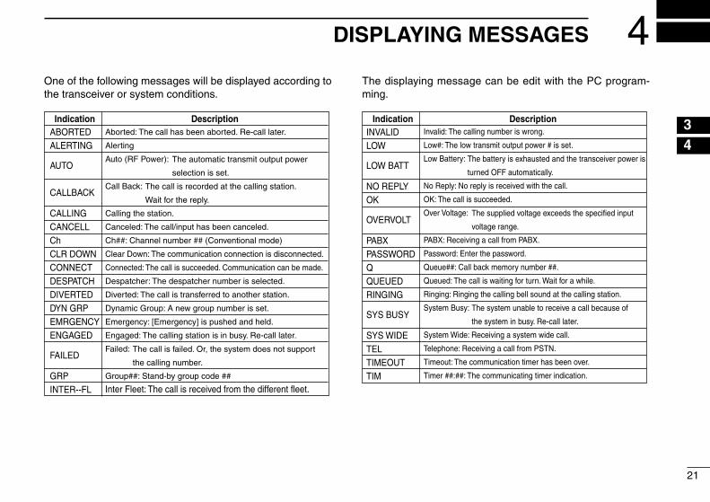
One of the follow�ng messages w�ll be d�splayed accord�ng to the transce�ver or system cond�t�ons.
The d�splay�ng message can be ed�t w�th the PC program-m�ng.
ABORTEDALERTING
AUTO
CALLBACK
CALLINGCANCELLChCLR DOWNCONNECTDESPATCHDIVERTEDDYN GRPEMRGENCYENGAGED
FAILED
GRPINTER--FL
Indication DescriptionAborted: The call has been aborted. Re-call later.
Alerting
Auto (RF Power):
Call Back:
Calling the station.
Canceled: The call/input has been canceled.
Ch##: Channel number ## (Conventional mode)
Clear Down: The communication connection is disconnected.
Connected: The call is succeeded. Communication can be made.
Despatcher: The despatcher number is selected.
Diverted: The call is transferred to another station.
Dynamic Group: A new group number is set.
Emergency: [Emergency] is pushed and held.
Engaged: The calling station is in busy. Re-call later.
Failed:
Group##: Stand-by group code ##
Inter Fleet: The call is received from the different fleet.
The automatic transmit output power
selection is set.
The call is recorded at the calling station.
Wait for the reply.
The call is failed. Or, the system does not support
the calling number.
IndicationINVALIDLOW
LOW BATT
NO REPLYOK
OVERVOLT
PABXPASSWORDQQUEUEDRINGING
SYS BUSY
SYS WIDETELTIMEOUTTIM
DescriptionInvalid: The calling number is wrong.
Low#: The low transmit output power # is set.
Low Battery:
No Reply: No reply is received with the call.
OK: The call is succeeded.
Over Voltage:
PABX: Receiving a call from PABX.
Password: Enter the password.
Queue##: Call back memory number ##.
Queued: The call is waiting for turn. Wait for a while.
Ringing: Ringing the calling bell sound at the calling station.
System Busy:
System Wide: Receiving a system wide call.
Telephone: Receiving a call from PSTN.
Timeout: The communication timer has been over.
Timer ##:##: The communicating timer indication.
The battery is exhausted and the transceiver power is
turned OFF automatically.
The supplied voltage exceeds the specified input
voltage range.
The system unable to receive a call because of
the system in busy. Re-call later.
21
4DISPLAYING MESSAGES
12345678910111213141516

22
5 OTHER FUNCTIONS
■ PTT quick callThe PTT qu�ck call prov�des s�mple call�ng.Push�ng [PTT] only makes a call w�th the d�splayed ID, even �nd�v�dual, group, despatcher, status or call back.
NOTE: The PTT qu�ck call w�ll not funct�on when [Call Set Up] �s ass�gned to some funct�on key. Do not ass�gn [Call Set Up] when PTT qu�ck funct�on �s used.
■ Call back functionUse th�s funct�on when the called stat�on cannot be reply the call �mmed�ately.Push and hold [Call Back] to toggle the call back funct�on ON and OFF.
When the call back function is turned ON:The called stat�on send�ng backs the “Call Back” message to the call�ng stat�on.• “ ” appears and the call�ng stat�on code �s stored �nto the
call back memory.• “CALLBACK” �s d�splayed on the call�ng stat�on d�splay.• Wh�le �n call back mode, two dot �nd�cat�ons bl�nk at the left
edge and 2nd of the LCD.
When the call back function is turned OFF:The call�ng stat�on code �s stored �nto the call back memory only when no reply call �s performed, or the clear down oper-at�on �s performed at the call�ng stat�on before reply the call.• Up to 15 calls can be stored �nto the call back memory.• “ ” bl�nks to let operator knows the un-repl�ed calls are
ava�lable.• When [Call Back] �s pushed to confirm the stored contents,
the call back �nd�cator bl�nk�ng stops and d�splayed cont�nu-ously.
• The call back memory �s cleared after turn�ng the trans-ce�ver OFF.
• The regular calling operation can be performed even the call back function is turned ON.
q Dur�ng “ ” appears or bl�nks, push [Call Back] to d�splay the stored stat�on code or text name.
w Push [Up]/[Down] to select the des�red memory.e Push [PTT], [Call Set Up] or [#] to reply to the call that
from the selected stat�on code. • The stat�on code w�ll be erased from the call back mem-
ory when the reply call �s performed. • The call back operat�on cannot be performed to PSTN,
PABX, Inter-prefix and Inter-fleet calls.

• Erasing the call back memoryq Push [Call Back] then select the des�red call back memory
to be erased w�th [Up]/[Down].w Push and hold [Call Back] for 2.5 sec. to erase the se-
lected call back memory. • All the stored call back memory can be erased w�th the
same operat�on as above depend�ng on the sett�ng. • When all of the 15 call back memor�es are stored and
16th call �s rece�ved, the called stat�on sent the message, “Don’t D�sturb” to the system repeater. In th�s case, the message that the call has fa�led �s d�splayed on the call-�ng stat�on d�splay.
■ Calling station ID indication for group call
The commun�cat�ng stat�on code can be d�splayed at any t�me.Th�s funct�on can be turned ON or OFF �n advance.
The “Pressel s�gnal” from the call�ng transce�ver �s used for the �nd�cat�on, however, the “Pressel s�gnal” �s not through out w�th some trunk�ng system repeater. No stat�on code �nd�ca-t�on �s prov�ded �n th�s case.
NOTE: Th�s funct�on may funct�on d�fferently or not func-t�on depend�ng on the trunk�ng system controller �n place.
23
5OTHER FUNCTIONS
12345678910111213141516

24
5 OTHER FUNCTIONS
■ System lock functionThe system lock funct�on d�sables the roam�ng funct�on man-ually.
q Push [M], [5], [1] and [#] �n sequence to turn the system lock funct�on ON.
• The dot �nd�cat�on appears at r�ght edge of the LCD.w Push [#], [5], [1] and [#] �n sequence to turn the system
lock funct�on OFF. • The dot �nd�cat�on d�sappears.
■ Call code memoryUp to 4 codes, �nd�v�dual, group or status, can be pro-grammed from the keypad.The programmed codes can be selected w�th [Up]/[Down].
➥ Push [M], [6], [0], [M], [x]*, [M], [code number] and [#] �n sequence to program the des�red code �nto the memory.
• No eras�ng capab�l�ty �s ava�lable, over-wr�te the new code �n such a case.
*x=1 to 4
■ Automatic transmit output power selection
(Except for the convent�onal operat�on)
Dur�ng trunk�ng operat�on, the transm�t output power �s au-tomat�cally selected from H�gh, Low2 and Low1 accord�ng to the rece�ved s�gnal strength from the system base.
■ Power ON securityThe transce�ver has a power ON secur�ty that requ�res the 4-d�g�t password entry at turn�ng the power ON.The transce�ver cannot be used unt�l the correct password �s entered.

■ Voice scramblerThe opt�onal vo�ce scrambler, UT-109 and UT-110, are ava�l-able.The scrambler w�ll be turned ON when the des�red scrambler code �s selected �n user set menu. (p. 26)• Use the UT-109 w�th the trunk�ng operat�on �s recommended.• The transce�ver has bu�lt-�n vo�ce scrambler (�nvers�on type).
NOTE: • The UT-110 (w�th roll�ng sett�ng) CANNOT be used w�th
the trunk�ng operat�on, because of the roll�ng synchron�-zat�on w�ll be sh�fted by the �nterval transm�ss�on for the system.
• Both the UT-109 and UT-110 are usable for convent�onal operat�on.
• The bu�lt-�n vo�ce scrambler does not have a compat�b�l-�ty w�th the UT-109 and UT-110.
■ DTMF operationWh�le push�ng and hold�ng [PTT], push a key ([0] to [9], [P0] to [P3]*, [M] and [#]) to output the appropr�ate DTMF tone.The transce�ver should be �n the cond�t�on that the commun�-cat�on �s enabled w�th [PTT] on a traffic channel.*[P0] to [P3] correspond to the DTMF tone A to D, respect�vely.
■ Compander functionWhen the compander funct�on �s set to ON, the commun�cat-�ng aud�o qual�ty w�ll be �ncreased.The compander funct�on can be turned ON or OFF �n user set menu. (p. 26)
25
5OTHER FUNCTIONS
12345678910111213141516

26
6 USER SET MENU
■ User set menuDur�ng stand-by cond�t�on (not �n commun�cat�ng, d�al�ng, ac-cess�ng to some funct�on), push and hold [Clear] for 2.5 sec. to access to user set menu.In user set menu, backl�ght, r�nger, beep level, squelch level, compander, m�crophone ga�n, vo�ce scrambler, battery volt-age �nd�cat�on, etc., can be set.Unnecessary �tems can be h�dden from �nd�cat�on of user set menu.
q Push and hold [Clear] for 2.5 sec. to enter user set menu.w Push [Clear] momentar�ly to select the des�red set �tem.e Push [Up]/[Down] to set the des�red cond�t�on or value.r Push and hold [Clear] for 2.5 sec. aga�n to ex�t from user
set menu and return to the stand-by cond�t�on.
D Selectable items and setting value selectableitems settingvalues(down↔up)
• Backl�ght OFF, Auto, Auto2 or ON • R�nger OFF or ON • Beep level OFF or ON • Squelch level 0 to 255 • Compander OFF or ON • M�crophone Ga�n 1 to 5 • Vo�ce scrambler* OFF, 1 to 5 • Battery voltage �nd�cat�on OFF or ON * For opt�onal vo�ce scrambler sett�ng. Th�s �tem does not appear
when the opt�onal vo�ce scrambler un�t �s not �nstalled.
NOTE: NEVER decrease the squelch value from the �n�t�al sett�ng. Search�ng speed w�ll be decreased for trunk�ng system operat�on.

• Channel number indicationWhen the system �nformat�on �nd�cat�on �s enabled, the op-erat�ng channel number �s d�splayed w�th the commun�cat�on t�mer.
0014 0 59
“Enable” Channel number and t�mer �nd�cat�on
TIM 0 59
“D�sable” T�mer �nd�cat�on
D CPU revision indicationWh�le push�ng and hold�ng [P3] and [Up], turn the transce�ver power ON to �nd�cate the follow�ng �nformat�on.
• CPU rev�s�on number and check some• ESN number• Clone comment (1) and (2)• Installed opt�onal un�t name (�f �nstalled)
27
6USER SET MENU
12345678910111213141516
28
7 TALK AROUND
The transce�ver has a convent�onal operat�on capab�l�ty also for when the transce�ver �s �n out-of serv�ce area.The tone squelch operat�on w�th CTCSS �s ava�lable for the convent�onal operat�on, as well as the ANI (Automat�c Num-ber�ng Ident�ficat�on) transm�ss�on at PTT ON and/or OFF.
NOTE: The pressel s�gnal of trunk�ng �s used for the ANI operat�on.
➥ By push�ng [Mon�tor], both the tone and no�se squelch �s released to mon�tor the selected channel cond�t�ons.
➥ Total of 32 convent�onal channels are ava�lable and are se-lectable w�th [Up]/[Down].
The convent�onal channels must be programmed �n ad-vance.
• Switching with the automatic talk aroundThe convent�onal mode w�ll be selected automat�cally when the trunk�ng control channel �s fall down or the transce�ver move �nto the out-of serv�ce area.Even the convent�onal mode �s selected, the transce�ver automat�cally search�ng for a usable control channel by re-turn�ng �nto trunk�ng mode �n �nterval. Then the transce�ver �s sw�tched to trunk�ng mode when a usable control channel �s found, or return to convent�onal mode when no usable control channel �s found.The automat�c talk around �s d�sabled by sett�ng “OFF” �n au-tomat�c talk around t�mer w�th the programm�ng.
• Switching with [Mode], or [P1] and [Up] operation at power ON.
Push [Mode] to toggle the operat�on mode between trunk�ng and convent�onal mode.Or, wh�le push�ng and hold�ng both [P1] and [Up], turn the transce�ver power ON to toggle the operat�on mode between trunk�ng and convent�onal mode.Once the operat�on mode �s selected w�th e�ther opera-t�on, the operat�on mode won’t be changed unt�l [Mode] �s pushed.Even the transce�ver �s turned OFF, the transce�ver rema�ns the operat�on mode.
NOTE: [Mode] must be ass�gned �n key ass�gnment for both trunk�ng and convent�onal �f manual operat�on mode select�on �s requ�red.
■ Programmable function keysThe follow�ng funct�ons can be ass�gned to [Red], [Clear], [P0], [P1], [P2] and [P3] programmable funct�on keys.2 keys located below [PTT] are fixed for [Up] and [Down].A d�fferent funct�ons can be ass�gned for the custom�ze keys between trunk�ng and convent�onal mode.
D Trunking mode onlyDESPATCHER KEYPush to make the despatcher call.• The pre-programmed despatcher ID �s s�mply recalled.
CALL1 AND CALL2 KEYSPush to make a call to the pre-programmed stat�on/group.• [Call 1] calls the stat�on programmed �n channel 1 �n call memory.• [Call 2] calls the stat�on programmed �n channel 2 �n call memory.
EMERGENCY KEYPush to make an emergency call.The emergency call calls the pre-programmed stat�on.• Th�s funct�on �s ass�gned to [Red] �n default sett�ng.
BACKSPACE KEYPush to erase the prev�ously entered d�g�t �nput.
STATUS KEYPush to enter a status message select�on mode.
CALL BACK KEYPush to toggle the call back mode ON and OFF.
CALL SET UP KEYPush to make a call.Ass�gn th�s funct�on when the PTT qu�ck call �s not used.
D Either trunking or conventional modeMODE KEYPush to sw�tch the operat�on mode between trunk�ng and convent�onal.
NULL KEYNo funct�on.Ass�gn to the key that �s not used to the transce�ver opera-t�on.
HIGH/LOW KEYPush to toggle the transm�t output power.• When automat�c power select�on �s enabled for trunk�ng mode op-
erat�on, the transm�t output power cannot be selected w�th th�s key.
29
8PROGRAMMABLE FUNCTIONS
12345678910111213141516

30
8 PROGRAMMABLE FUNCTIONS
UP AND DOWN KEYS➥Push to select the call memory channel.➥Push to select the call back memory channel.➥Push to select the status channel.➥ Push to select the operat�ng channel. (Convent�onal mode
operat�on only)➥ Push to select the sett�ng value or cond�t�on dur�ng user
set mode.➥ Push to erase the prev�ously entered d�g�t number (func-
t�ons as back space key) dur�ng d�al�ng number enter�ng from the keypad. (10-key vers�on only)
LOCK KEYPush to �nh�b�t the funct�on key operat�ons, except [PTT] and [Lock].
CLEAR (SET MODE) KEY➥Push to d�sconnect the commun�cat�on (clear down).➥Push and hold for 2.5 sec. to enter user set menu.
D Conventional mode onlyMONITOR KEYPush to release both the tone and no�se squelch mute at the same t�me to mon�tor the s�gnal on the selected operat�ng channel.
SIMPLEX KEYThe both rece�ve frequency and rece�ve CTCSS frequency are used as the transm�t frequency and transm�t CTCSS fre-quency, respect�vely.D�rect commun�cat�on w�thout a repeater can be made.

■ UT-109 and UT-110 installationInstall the opt�onal un�t as follows:
q Rotate [VOL] to turn the power OFF, and remove the bat-tery pack. (p. 2)
w Remove the un�t cover. NOTE: Insert a standard screw dr�ver �nto the hollow of the chas-
s�s, then l�ft and take away the un�t cover �llustrated as below. Use the supplied spare unit cover! Do not use the cover that
has been removed once. Water or dust may get �nto the trans-ce�ver because the cover may be bent or has lost �t’s adhes�on. Th�s may result �n the transce�ver be�ng damaged.
e Cut the pattern on the PCB at the TX m�c c�rcu�t (MIC) and RX AF c�rcu�t (DISC) as shown below.
r Install the un�t as shown below.
*This illustration is described with the UT-109.
t Replace the un�t cover and the battery pack, then rotate [VOL] to turn the power ON.
NOTE: When uninstalling the scrambler unitBe sure to re-solder the d�sconnected po�nts at left, other-w�se no TX modulat�on or AF output �s ava�lable.
31
9OPTIONAL UNIT INSTALLATION
12345678910111213141516

32
10 BATTERY CHARGING
■ Caution
M�suse of L�th�um-Ion batter�es may result �n the fol-low�ng hazards: smoke, fire, or the battery may rupture. M�suse can also cause damage to the battery or degra-dat�on of battery performance.
R DANGER! Use and charge only spec�fied Icom battery packs w�th Icom rad�os or Icom chargers. Only Icom battery packs are tested and approved for use and charge w�th Icom rad�os or Icom chargers. Us�ng th�rd-party or counterfe�t bat-tery packs or chargers may cause smoke, fire, or cause the battery to burst.
D Battery cautionR DANGER! DO NOT hammer or otherw�se �mpact the bat-tery. Do not use the battery �f �t has been severely �mpacted or dropped, or �f the battery has been subjected to heavy pressure. Battery damage may not be v�s�ble on the outs�de of the case. Even �f the surface of the battery does not show cracks or any other damage, the cells �ns�de the battery may rupture or catch fire.
R DANGER! NEVER use or leave battery packs �n areas w�th temperatures above +60˚C. H�gh temperature bu�ldup �n the battery, such as could occur near fires or stoves, �ns�de a sun heated car, or �n d�rect sunl�ght may cause the battery to rupture or catch fire. Excess�ve temperatures may also de-grade battery performance or shorten battery l�fe.
R DANGER! DO NOT expose the battery to ra�n, snow, seawater, or any other l�qu�ds. Do not charge or use a wet battery. If the battery gets wet, be sure to w�pe �t dry before us�ng. The battery �s not waterproof.
R DANGER! NEVER �nc�nerate used battery packs s�nce �n-ternal battery gas may cause them to rupture, or may cause an explos�on.
R DANGER! NEVER solder the battery term�nals or NEVER mod�fy the battery pack. Th�s may cause heat generat�on, and the battery may rupture, em�t smoke or catch fire.
R DANGER! Use the battery only w�th the transce�ver for wh�ch �t �s spec�fied. Never use a battery w�th any other equ�p-ment, or for any purpose that �s not spec�fied �n th�s �nstruc-t�on manual.
R DANGER! If flu�d from �ns�de the battery gets �n your eyes, bl�ndness can result. R�nse your eyes w�th clean water, w�th-out rubb�ng them, and see a doctor �mmed�ately.

WARNING! Immed�ately stop us�ng the battery �f �t em�ts an abnormal odor, heats up, or �s d�scolored or deformed. If any of these cond�t�ons occur, contact your Icom dealer or d�s-tr�butor.
WARNING! Immed�ately wash, us�ng clean water, any part of the body that comes �nto contact w�th flu�d from �ns�de the battery.
WARNING! NEVER put the battery �n a m�crowave oven, h�gh-pressure conta�ner, or �n an �nduct�on heat�ng cooker. Th�s could cause a fire, overheat�ng, or cause the battery to rupture.
CAUTION! Always use the battery w�th�n the spec�fied tem-perature range for the transce�ver (–25˚C to +55˚C) and the battery �tself (–20˚C to +60˚C). Us�ng the battery out of �ts spec�fied temperature range w�ll reduce the battery’s perfor-mance and battery l�fe. Please note that the spec�fied temper-ature range of the battery may exceed that of the transce�ver. In such cases, the transce�ver may not work properly because �t �s out of �ts operat�ng temperature range.
CAUTION! Shorter battery l�fe could occur �f the battery �s left fully charged, completely d�scharged, or �n an excess�ve tem-perature env�ronment (above +45˚C) for an extended per�od of t�me. If the battery must be left unused for a long t�me, �t must be detached from the rad�o after d�scharg�ng. You may use the battery unt�l the battery �nd�cator shows half-capac�ty, then keep �t safely �n a cool dry place w�th the temperature between –20˚C to +25˚C.
D Charging cautionR DANGER! NEVER charge the battery pack �n areas w�th extremely h�gh temperatures, such as near fires or stoves, �ns�de a sun heated car, or �n d�rect sunl�ght. In such env�ron-ments, the safety/protect�on c�rcu�t �n the battery w�ll act�vate, caus�ng the battery to stop charg�ng.
WARNING! DO NOT charge or leave the battery �n the bat-tery charger beyond the spec�fied t�me for charg�ng. If the battery �s not completely charged by the spec�fied t�me, stop charg�ng and remove the battery from the battery charger. Cont�nu�ng to charge the battery beyond the spec�fied t�me l�m�t may cause a fire, overheat�ng, or the battery may rup-ture.
WARNING! NEVER �nsert the transce�ver (battery attached to the transce�ver) �nto the charger �f �t �s wet or so�led. Th�s could corrode the battery charger term�nals or damage the charger. The charger �s not waterproof.
CAUTION! DO NOT charge the battery outs�de of the spec�-fied temperature range: BC-160 (0˚C to +45˚C). Icom recom-mends charg�ng the battery at +20˚C. The battery may heat up or rupture �f charged out of the spec�fied temperature range. Add�t�onally, battery performance or battery l�fe may be reduced.
33
10BATTERY CHARGING
12345678910111213141516

34
10BATTERY CHARGING
■ Optional battery chargersD Rapid charging with the BC-160The opt�onal BC-160 prov�des rap�d charg�ng of opt�onal L�-Ion battery packs.• An AC adapter (may be suppl�ed w�th BC-160 depend�ng
on vers�on) or the DC power cable (OPC-515L/CP-17L) �s add�t�onally requ�red.
AC adapter(Not supplied with some versions.)
Optional OPC-515L (for 13.8 V power source) or CP-17L (for 12 V cigarette lighter socket) can be used instead of the AC adapter.
BATTERY PACK
TRANSCEIVER
Turn power OFF
D AD-106 installationThe AD-106 charger adapter must be �nstalled �nto the BC-119N or BC-121N before battery charg�ng.
➥Connect the AD-106 charger adapter and the BC-119N/ BC-121N as below, then �nstall the AD-106 �nto the holder space of the BC-119N or BC-121N w�th the suppl�ed screws.
Screws supplied with the charger adapter
AD-106
Connectors
Plugs

D Rapid charging with the BC-119N+AD-106The opt�onal BC-119N prov�des rap�d charg�ng of battery packs. The follow�ng �tems are add�t�onally requ�red.• AD-106 charger adapter• An AC adapter (may be suppl�ed w�th BC-119N depend�ng
on vers�on) or the DC power cable (OPC-515L/CP-17L).
AD-106 charger adapter is installed in BC-119N.
AC adapter(Not supplied with some versions.)
Optional OPC-515L (for 13.8 V power source) or CP-17L (for 12 V cigarette lighter socket) can be used instead of the AC adapter.
TRANSCEIVER
BATTERY PACK
Turn power OFF
D Rapid charging with the BC-121N+AD-106The opt�onal BC-121N allows up to 6 battery packs to be charged s�multaneously. The follow�ng �tems are add�t�onally requ�red.• S�x AD-106 charger adapters• An AC adapter (BC-157) or the DC power cable (OPC-656)
AC adapter(Purchase separately)
AD-106 chargeradapters are installedin each slot.
DC power cable (OPC-656)(Connect with the DC power supply; 13.8 V/at least 7 A)
TRANSCEIVERBATTERYPACK
Turn power OFF
35
10BATTERY CHARGING
12345678910111213141516

36
10BATTERY CHARGING
IMPORTANT!: Battery chargingEnsure the gu�de lobs on the battery pack are correctly al�gned w�th the gu�de ra�ls �ns�de the charger adapter. (Th�s �llustrat�on �s descr�bed w�th the BC-160.)
Gu�de ra�l
Lobs
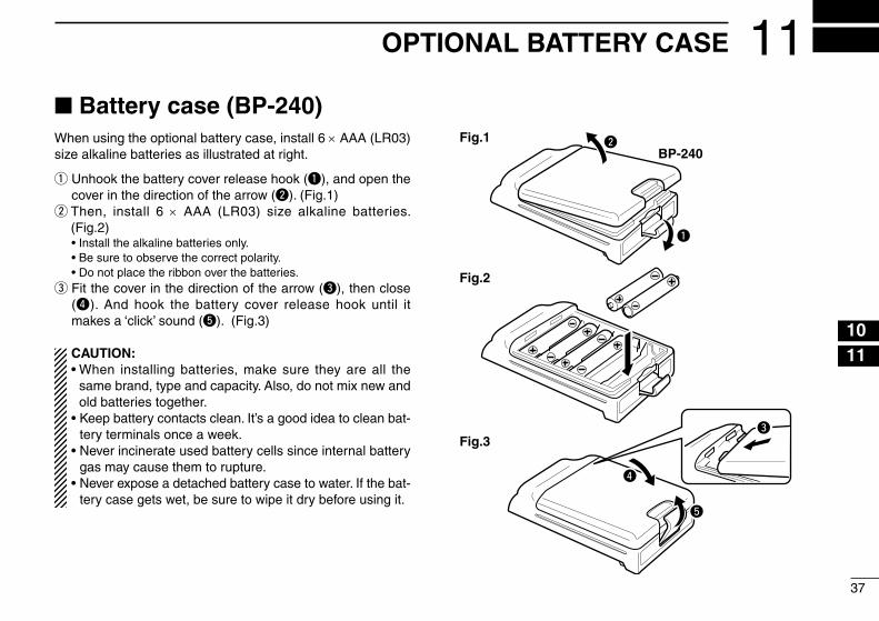
■ Battery case (BP-240)When us�ng the opt�onal battery case, �nstall 6 × AAA (LR03) s�ze alkal�ne batter�es as �llustrated at r�ght.
q Unhook the battery cover release hook (q), and open the cover �n the d�rect�on of the arrow (w). (F�g.1)
w Then, �nstall 6 × AAA (LR03) s�ze alkal�ne batter�es. (F�g.2)
• Install the alkal�ne batter�es only. • Be sure to observe the correct polar�ty. • Do not place the r�bbon over the batter�es.e F�t the cover �n the d�rect�on of the arrow (e), then close
(r). And hook the battery cover release hook unt�l �t makes a ‘cl�ck’ sound (t). (F�g.3)
CAUTION:• When �nstall�ng batter�es, make sure they are all the
same brand, type and capac�ty. Also, do not m�x new and old batter�es together.
• Keep battery contacts clean. It’s a good �dea to clean bat-tery term�nals once a week.
• Never �nc�nerate used battery cells s�nce �nternal battery gas may cause them to rupture.
• Never expose a detached battery case to water. If the bat-tery case gets wet, be sure to w�pe �t dry before us�ng �t.
q
BP-240wFig.1
Fig.2
Fig.3e
r
t
37
11OPTIONAL BATTERY CASE
12345678910111213141516

38
12 OPTIONAL SWIVEL BELT CLIP
■ MB-93 contents Qty.q Belt cl�p ........................................................................... 1w Base cl�p ......................................................................... 1
q w
■ Attachingq Release the battery pack �f �t �s attached. (p. 2)w Sl�de the base cl�p �n the d�rect�on of the arrow unt�l the
base cl�p �s locked and makes a ‘cl�ck’ sound.
e Cl�p the belt cl�p to a part of your belt. And �nsert the transce�ver �nto the belt cl�p unt�l the base cl�p �nserted fully �nto the groove.
r Once the transce�ver �s locked �n place, �t sw�vels as �llustrated below.

■ Detachingq Turn the transce�ver ups�de down �n the d�rect�on of the
arrow and pull out from the belt cl�p.w Release the battery pack �f �t �s attached. (p. 2)e P�nch the cl�p (q), and sl�de the base cl�p �n the d�rect�on
of the arrow (w).
qw
CAUTION:HOLD THE TRANSCEIVER TIGHTLY, WHEN HANGING OR DETACHING THE TRANSCEIVER FROM THE BELT CLIP.Otherw�se the transce�ver may not be attached to the holder or sw�vel properly �f the transce�ver �s acc�dentally dropped and the base cl�p �s scratched or damaged.
39
12OPTIONAL SWIVEL BELT CLIP
12345678910111213141516
40
13 OPTIONS
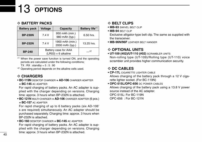
D BATTERY PACKSBattery pack Voltage Capacity Battery life*1
BP-230N 7.4 V950 mAh (m�n.)980 mAh (typ.)
6.50 hrs.
BP-232N 7.4 V1900 mAh (m�n.)2000 mAh (typ.)
13.25 hrs.
BP-240Battery case for AAA (LR03) × 6 alkal�ne
—*2
*1 When the power save funct�on �s turned ON, and the operat�ng per�ods are calculated under the follow�ng cond�t�ons;
TX : RX : standby = 5 : 5 : 90*2 Operat�ng per�od depends on the alkal�ne cells used.
D CHARGERS• BC-119N desktop charger + AD-106 charger adapter
+ BC-145 ac adapter
For rap�d charg�ng of battery packs. An AC adapter �s sup-pl�ed w�th the charger depend�ng on vers�ons. Charg�ng t�me: approx. 3 hours when BP-232N �s attached.
• BC-121N multi-charger + AD-106 charger adapter (6 pcs.) + BC-157 ac adapter
For rap�d charg�ng of up to 6 battery packs (s�x AD-106’s are requ�red) s�multaneously. An AC adapter should be purchased separately. Charg�ng t�me: approx. 3 hours when BP-232N �s attached.
• BC-160 desktop charger + BC-145 ac adapter
For rap�d charg�ng of battery packs. An AC adapter �s sup-pl�ed w�th the charger depend�ng on vers�ons. Charg�ng t�me: approx. 3 hours when BP-232N �s attached.
D BELT CLIPS• MB-93 swivel belt clip
• MB-94 belt clip
Exclus�ve all�gator-type belt cl�p. The same as suppl�ed w�th the transce�ver.
• MB-96N/96F leather belt hanger
D OPTIONAL UNITS• UT-109 (#02)/UT-110 (#02) scrambler units
Non-roll�ng type (UT-109)/Roll�ng type (UT-110) vo�ce scrambler un�t prov�des h�gher commun�cat�on secur�ty.
D DC CABLES• CP-17L cigarette lighter cable
Allows charg�ng of the battery pack through a 12 V c�ga-rette l�ghter socket. (For BC-119N)
• OPC-515L/OPC-656 dc power cables
Allows charg�ng of the battery pack us�ng a 13.8 V power source �nstead of the AC adapter.
OPC-515L: For BC-119N OPC-656 : For BC-121N

D OTHER OPTIONS• SP-13 earphone
Prov�des clear rece�ve aud�o �n no�sy env�ronment.• HM-131L/HM-158L speaker-microphone
Comb�nat�on speaker-m�crophone that prov�des conven�ent operat�on wh�le hang�ng the transce�ver from your belt.
• HS-94/HS-95/HS-97 headset + VS-1L vox/ptt case
HS-94: Ear-hook type HS-95: Neck-arm type HS-97: Throat m�crophone VS-1L: VOX/PTT sw�tch box for hands-free operat�on, etc.• FA-SC73US stubby antenna
Shorter UHF antenna. Frequency range: 450–490 MHz• FA-SC25U flexible antenna
UHF antenna. Frequency range: 400–430 MHz• FA-SC57U flexible antenna
UHF antenna. Frequency range: 430–470 MHz
Some opt�ons may not be ava�lable �n some countr�es. Please ask your dealer for deta�ls.
41
13OPTIONS
12345678910111213141516

42
14 DOC
CE vers�ons of the IC-F44GT/GS wh�ch d�splay the “CE” symbol on the ser�al number seal, com-ply w�th the essent�al requ�rements of the Euro-pean Rad�o and Telecommun�cat�on Term�nal D�rect�ve 1999/5/EC.
Th�s warn�ng symbol �nd�cates that th�s equ�p-ment operates �n non-harmon�sed frequency bands and/or may be subject to l�cens�ng cond�-t�ons �n the country of use. Be sure to check that you have the correct vers�on of th�s rad�o or the correct programm�ng of th�s rad�o, to comply w�th nat�onal l�cens�ng requ�rement.
DECLARATIONOF CONFORMITY
We Icom Inc. Japan1-1-32, Kamiminami, Hirano-kuOsaka 547-0003, Japan
Kind of equipment: UHF TRANSCEIVER
Type-designation: iC- f44gt/gs
Signature
Authorized representative name
Place and date of issue
Declare on our sole responsibility that this equipment complies with theessential requirements of the Radio and Telecommunications Terminal Equipment Directive, 1999/5/EC, and that any applicable Essential TestSuite measurements have been performed.
Version (where applicable):
This compliance is based on conformity with the following harmonised standards, specifications or documents:i) EN 301 489-1 v1.3.1 (Sept 2001)ii) EN 301 489-5 (August 2000)iii) EN 60950 (August 1992+A11) iv) EN 300 086-2 (March 2001) v) EN 300 219-2 (March 2001)vi) EN 300 113-2 (March 2001)
400–470 MHz 12.5 kHz/20 kHz/25 kHz
0168Düsseldorf 30th Apr. 2004

43
MEMO
12345678910111213141516

1-1-32 Kam�m�nam�, H�rano-ku, Osaka 547-0003, Japan
A-6580H-1EU-wPr�nted �n Japan© 2007–2009 Icom Inc.
Pr�nted on recycled paper w�th soy �nk.
< Intended Country of Use > GER AUT GBR IRL NOR
FRA NED BEL LUX
ESP POR ITA GRE
SWE DEN FIN SUI