uhf gen2 rfid where do we go from here?2009.ieee-rfid.org/files/2011/12/diorio_ieee_final.pdf ·...
TRANSCRIPT
2
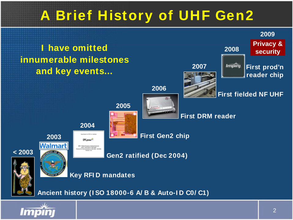
A Brief History of UHF Gen2
First Gen2 chip
Gen2 ratified (Dec 2004)
First DRM reader
First fielded NF UHF
First prod’n reader chip
Ancient history (ISO 18000-6 A/B & Auto-ID C0/C1)
Key RFID mandates
Privacy & security
< 2003
2003
2004
2005
2006
2007
2008
2009
I have omitted innumerable milestones
and key events…
3
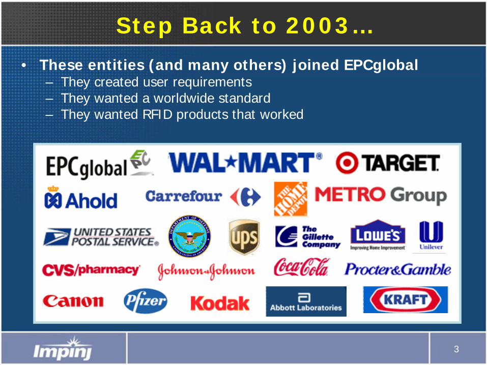
Step Back to 2003…
• These entities (and many others) joined EPCglobal– They created user requirements– They wanted a worldwide standard– They wanted RFID products that worked
4
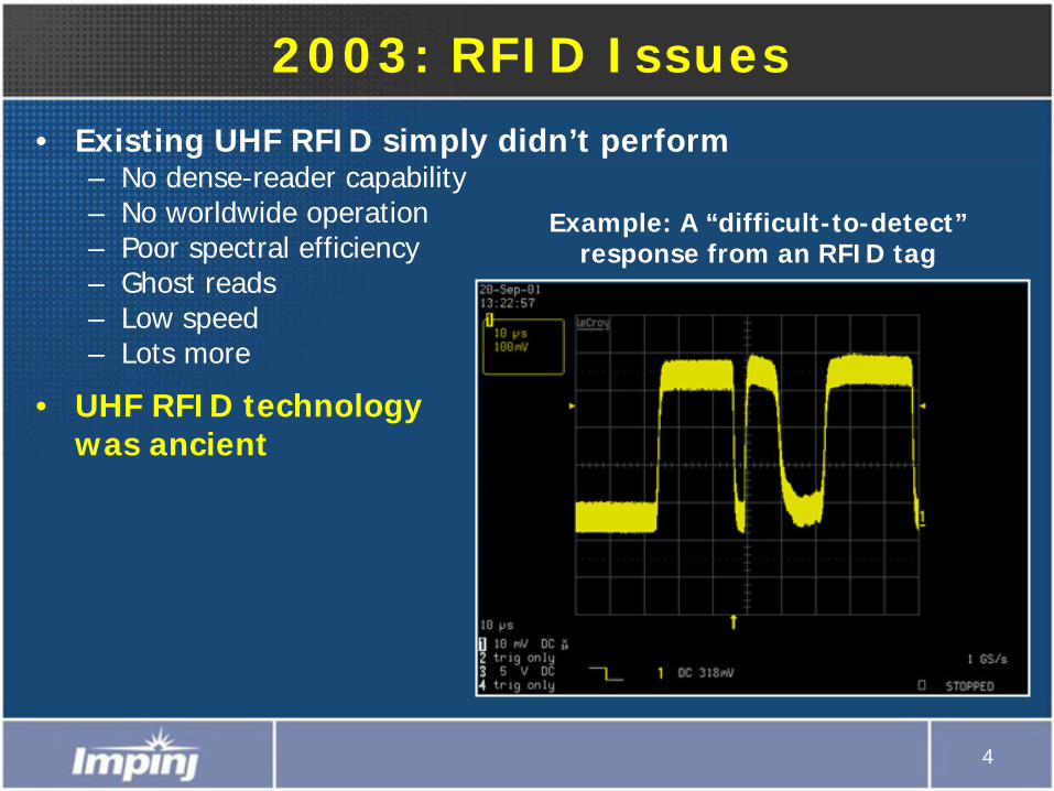
2003: RFID Issues
• Existing UHF RFID simply didn’t perform– No dense-reader capability– No worldwide operation– Poor spectral efficiency– Ghost reads– Low speed– Lots more
• UHF RFID technology was ancient
Example: A “difficult-to-detect” response from an RFID tag
5
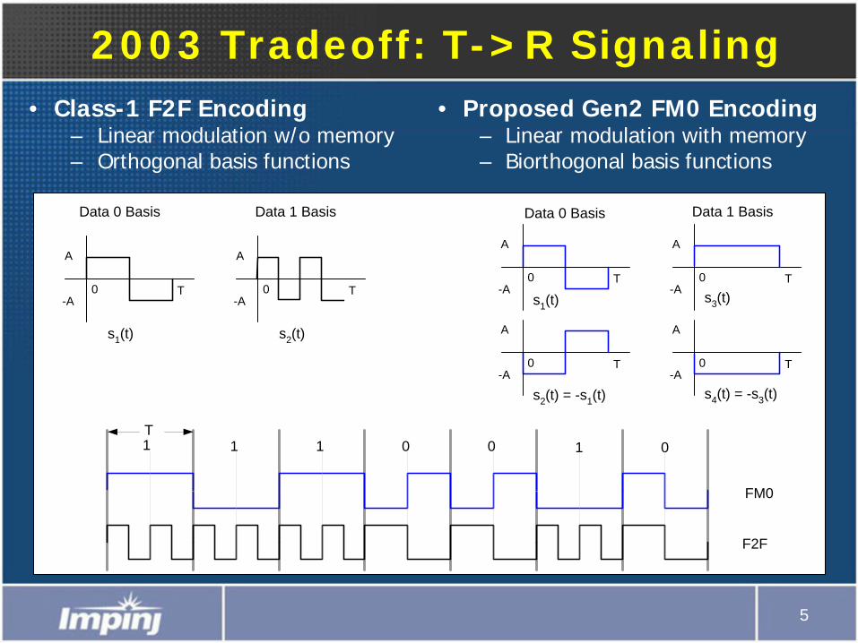
2003 Tradeoff: T->R Signaling• Proposed Gen2 FM0 Encoding
– Linear modulation with memory– Biorthogonal basis functions
• Class-1 F2F Encoding– Linear modulation w/o memory– Orthogonal basis functions
A
-A0 T
s1(t)
A
-A0 T
s2(t) = -s1(t)
A
-A0 T
s3(t)
A
-A0 T
s4(t) = -s3(t)
Data 0 Basis Data 1 Basis
A
-A0 T
s1(t)
A
-A0 T
s2(t)
Data 0 Basis Data 1 Basis
T
FM0
F2F
1 1 1 0 0 1 0
6
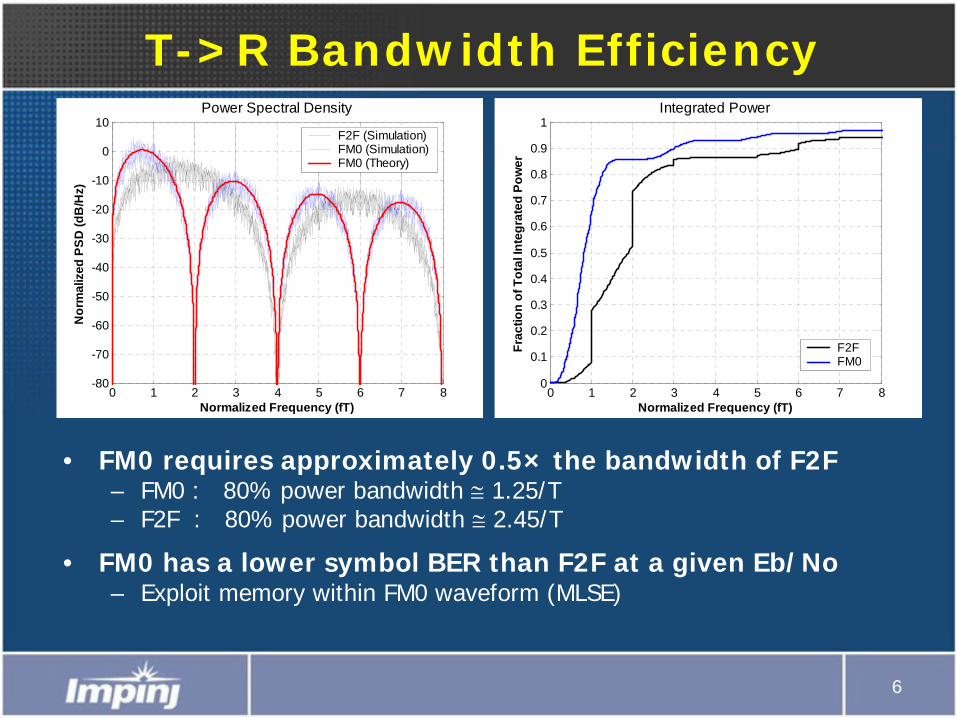
T->R Bandwidth Efficiency
• FM0 requires approximately 0.5× the bandwidth of F2F– FM0 : 80% power bandwidth ≅
1.25/T – F2F : 80% power bandwidth ≅
2.45/T
• FM0 has a lower symbol BER than F2F at a given Eb/No– Exploit memory within FM0 waveform (MLSE)
0 1 2 3 4 5 6 7 8-80
-70
-60
-50
-40
-30
-20
-10
0
10
Normalized Frequency (fT)
Nor
mal
ized
PSD
(dB
/Hz)
Power Spectral Density
F2F (Simulation)FM0 (Simulation)FM0 (Theory)
0 1 2 3 4 5 6 7 80
0.1
0.2
0.3
0.4
0.5
0.6
0.7
0.8
0.9
1
Normalized Frequency (fT)
Frac
tion
of T
otal
Inte
grat
ed P
ower
Integrated Power
F2FFM0
7
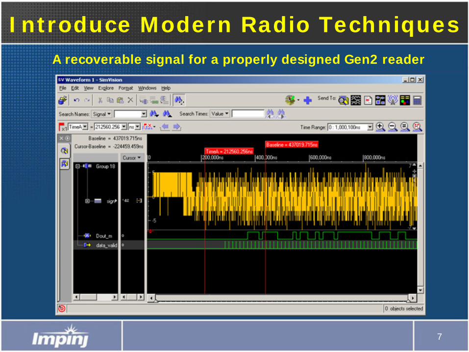
Introduce Modern Radio TechniquesA recoverable signal for a properly designed Gen2 reader
8
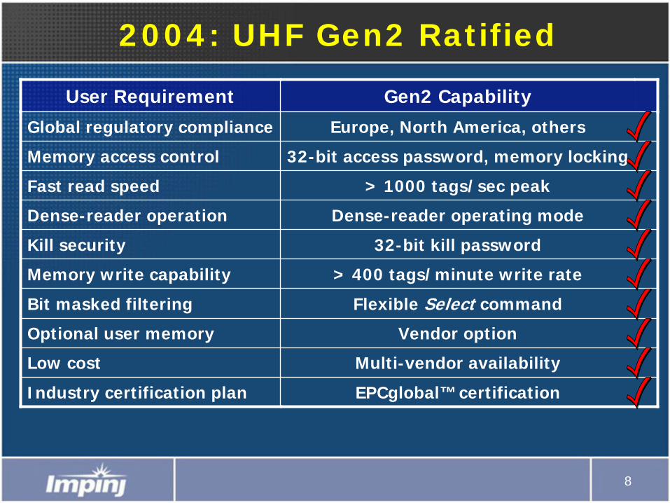
2004: UHF Gen2 Ratified
User Requirement Gen2 Capability
Global regulatory compliance Europe, North America, others
Memory access control 32-bit access password, memory locking
Fast read speed > 1000 tags/sec peak
Dense-reader operation Dense-reader operating mode
Kill security 32-bit kill password
Memory write capability > 400 tags/minute write rate
Bit masked filtering Flexible Select command
Optional user memory Vendor option
Low cost Multi-vendor availability
Industry certification plan EPCglobal™ certification
9
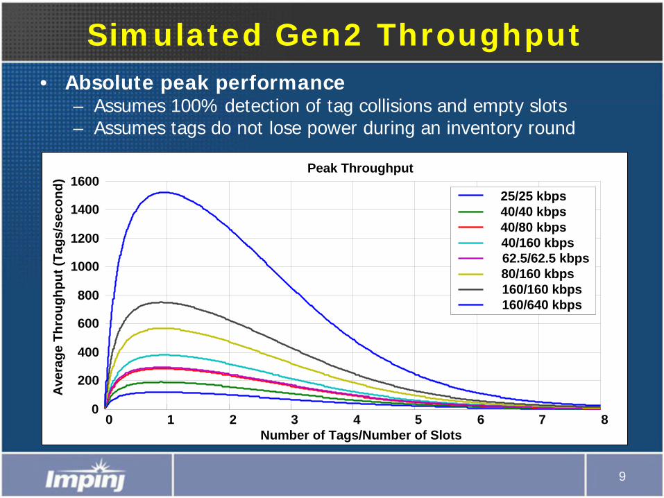
Simulated Gen2 Throughput• Absolute peak performance
– Assumes 100% detection of tag collisions and empty slots– Assumes tags do not lose power during an inventory round
0 1 2 3 4 5 6 7 80
200
400
600
800
1000
1200
1400
1600
Number of Tags/Number of Slots
Ave
rage
Thr
ough
put (
Tags
/sec
ond)
Peak Throughput
25/25 kbps40/40 kbps40/80 kbps40/160 kbps62.5/62.5 kbps80/160 kbps160/160 kbps160/640 kbps
10
FilterFilter
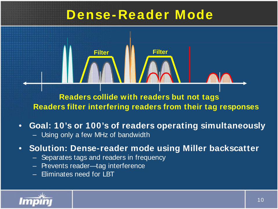
Dense-Reader Mode
• Goal: 10’s or 100’s of readers operating simultaneously– Using only a few MHz of bandwidth
• Solution: Dense-reader mode using Miller backscatter – Separates tags and readers in frequency– Prevents reader—tag interference– Eliminates need for LBT
Readers collide with readers but not tagsReaders filter interfering readers from their tag responses
11
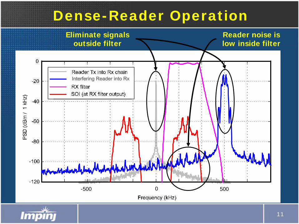
Dense-Reader OperationEliminate signals
outside filter
-500 0 500
Interfering Reader into Rx
Reader noise is low inside filter
12
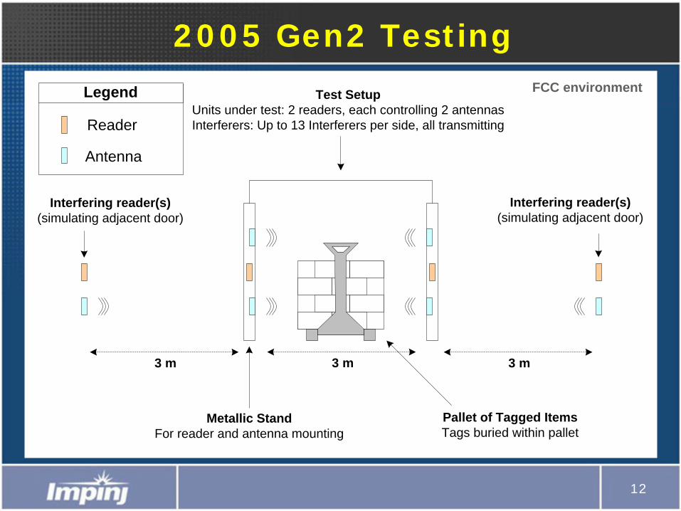
2005 Gen2 Testing
Test SetupUnits under test: 2 readers, each controlling 2 antennasInterferers: Up to 13 Interferers per side, all transmitting
Interfering reader(s)(simulating adjacent door)
Interfering reader(s) (simulating adjacent door)
Reader
Antenna
Legend
Metallic StandFor reader and antenna mounting
3 m3 m
Pallet of Tagged ItemsTags buried within pallet
3 m
FCC environment
13
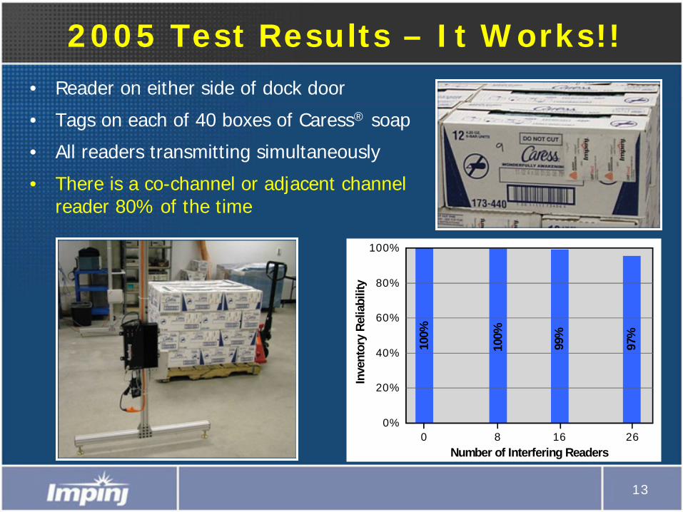
2005 Test Results – It Works!!• Reader on either side of dock door
• Tags on each of 40 boxes of Caress® soap
• All readers transmitting simultaneously
• There is a co-channel or adjacent channel reader 80% of the time
0%
20%
40%
60%
80%
100%
Inve
ntor
y Re
liabi
lity
Number of Interfering Readers
100%
100%
99%
97%
0 8 16 26
14
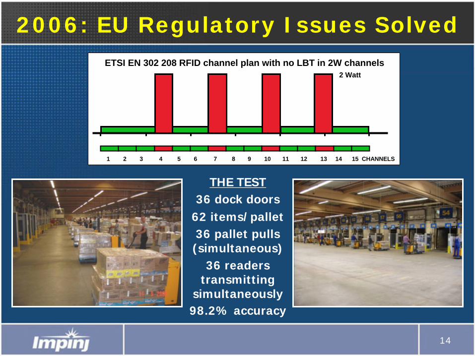
2006: EU Regulatory Issues SolvedETSI EN 302 208 RFID channel plan with no LBT in 2W channels
1 2 3 4 5 6 7 8 9 10 11 12 13 14 15 CHANNELS
2 Watt
THE TEST36 dock doors
62 items/pallet36 pallet pulls (simultaneous)
36 readers transmitting
simultaneously98.2% accuracy
15
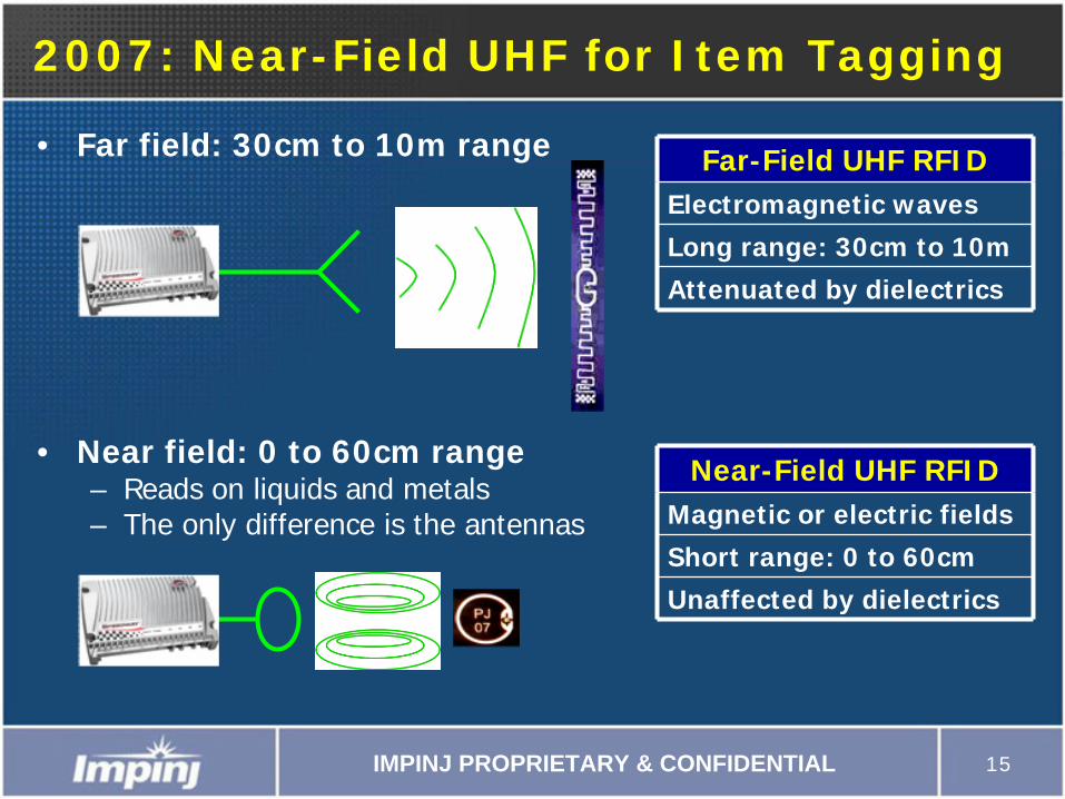
2007: Near-Field UHF for Item Tagging
Far-Field UHF RFIDElectromagnetic waves
Long range: 30cm to 10m
Attenuated by dielectrics
Near-Field UHF RFIDMagnetic or electric fields
Short range: 0 to 60cm
Unaffected by dielectrics
IMPINJ PROPRIETARY & CONFIDENTIAL
• Far field: 30cm to 10m range
• Near field: 0 to 60cm range– Reads on liquids and metals– The only difference is the antennas
16
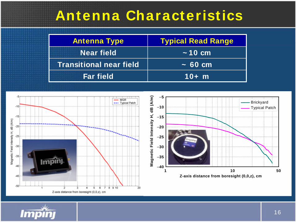
Antenna Characteristics
–40
–35
–30
–25
–20
–15
–10
–5
1 10 50
Typical PatchBrickyard
Mag
netic
Fie
ld In
tens
ity H
, dB
(A/m
)
Z-axis distance from boresight (0,0,z), cm
Antenna Type Typical Read Range
Near field ~10 cm
Transitional near field ~ 60 cm
Far field 10+ m
17
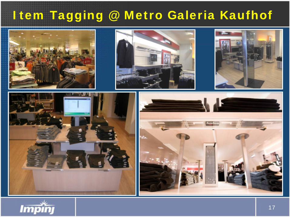
Item Tagging @ Metro Galeria Kaufhof
18
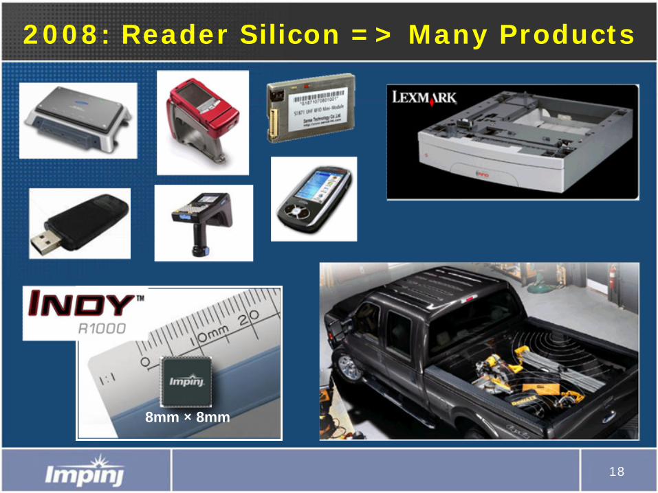
2008: Reader Silicon => Many Products
8mm ×
8mm
19
Enter 2009…
• We have a handle on many hard problems– Die sensitivity– Broadband inlay tuning– Inlay orientation insensitivity– Tag interference rejection– Reader sensitivity, selectivity, speed
20
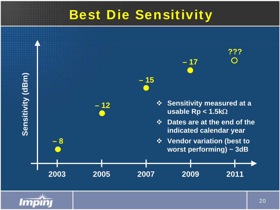
Best Die Sensitivity
2003 2005 2007 2009 2011
– 8
– 12
– 15
– 17???
Sens
itivi
ty (d
Bm
)
Sensitivity measured at a usable Rp < 1.5kΩDates are at the end of the indicated calendar yearVendor variation (best to worst performing) ~ 3dB
21
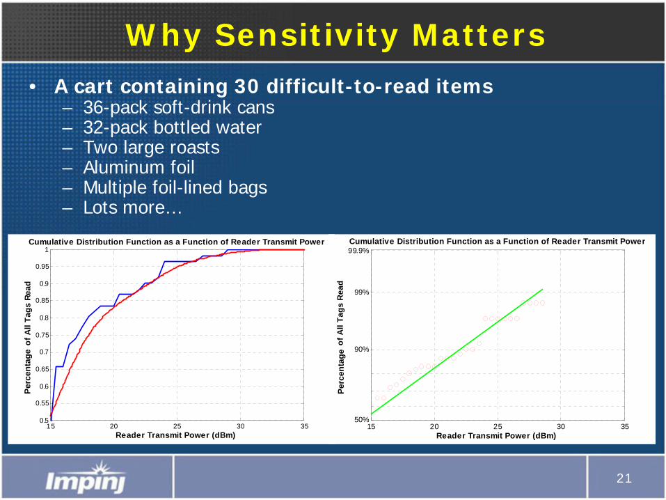
Why Sensitivity Matters• A cart containing 30 difficult-to-read items
– 36-pack soft-drink cans– 32-pack bottled water– Two large roasts– Aluminum foil– Multiple foil-lined bags– Lots more…
15 20 25 30 3550%
90%
99%
99.9%
Reader Transmit Power (dBm)
Pro
babi
lity
of A
ll Ta
gs R
ead
Cumulative Distribution Function as a Function of Reader Transmit Power
Perc
enta
ge
15 20 25 30 350.5
0.55
0.6
0.65
0.7
0.75
0.8
0.85
0.9
0.95
1
Reader Transmit Power (dBm)
Prob
abili
ty o
f All
Tags
Rea
d
Cumulative Distribution Function as a Function of Reader Transmit Power
Perc
enta
ge
22
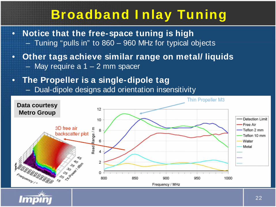
Broadband Inlay Tuning• Notice that the free-space tuning is high
– Tuning “pulls in” to 860 – 960 MHz for typical objects
• Other tags achieve similar range on metal/liquids– May require a 1 – 2 mm spacer
• The Propeller is a single-dipole tag– Dual-dipole designs add orientation insensitivity
Data courtesy Metro Group
23
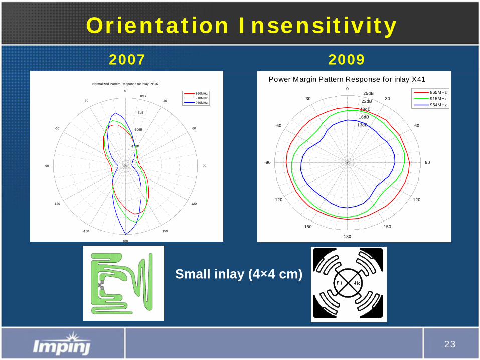
Orientation Insensitivity
13dB
16dB
19dB
22dB
25dB
-150
-120
-90
-60
-30
0
30
60
90
120
150
180
Power Margin Pattern Response for inlay X41
865MHz915MHz954MHz
-15dB
-10dB
-5dB
0dB
-150
-120
-90
-60
-30
0
30
60
90
120
150
180
Normalized Pattern Response for inlay PH16
860MHz910MHz960MHz
Small inlay (4×4 cm)
2007 2009
24
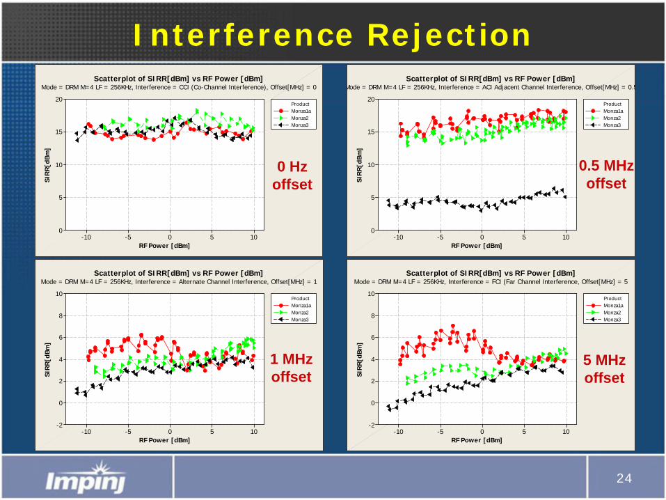
Interference Rejection
1050-5-10
20
15
10
5
0
RF Power [dBm]
SIR
R[d
Bm]
Monza1aMonza2Monza3
Product
Scatterplot of SIRR[dBm] vs RF Power [dBm]Mode = DRM M=4 LF = 256KHz, Interference = CCI (Co-Channel Interference), Offset[MHz] = 0
1050-5-10
20
15
10
5
0
RF Power [dBm]
SIR
R[d
Bm]
Monza1aMonza2Monza3
Product
Scatterplot of SIRR[dBm] vs RF Power [dBm]Mode = DRM M=4 LF = 256KHz, Interference = ACI Adjacent Channel Interference, Offset[MHz] = 0.5
1050-5-10
10
8
6
4
2
0
-2
RF Power [dBm]
SIR
R[d
Bm]
Monza1aMonza2Monza3
Product
Scatterplot of SIRR[dBm] vs RF Power [dBm]Mode = DRM M=4 LF = 256KHz, Interference = Alternate Channel Interference, Offset[MHz] = 1
1050-5-10
10
8
6
4
2
0
-2
RF Power [dBm]
SIR
R[d
Bm]
Monza1aMonza2Monza3
Product
Scatterplot of SIRR[dBm] vs RF Power [dBm]Mode = DRM M=4 LF = 256KHz, Interference = FCI (Far Channel Interference, Offset[MHz] = 5
0 Hz offset
0.5 MHz offset
1 MHz offset
5 MHz offset

25
+30dBm Reader Tx power
R=>T link path loss
T=>R link path loss
–15dBm
–70dBmNext-gen (2009 tags) sensitivity = –74dBm
Tag Distance from Reader
Pow
er (
dBm
)
–74dBm
Tag loss ~10dB
Required reader sensitivity = –70dBm
Reader Sensitivity RequirementsIf reader meets sensitivity requirements, then link is limited by tag sensitivity
26
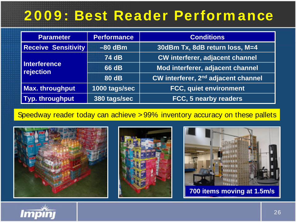
700 items moving at 1.5m/s
2009: Best Reader PerformanceParameter Performance Conditions
Receive Sensitivity –80 dBm 30dBm Tx, 8dB return loss, M=4
Interference rejection
74 dB CW interferer, adjacent channel66 dB Mod interferer, adjacent channel80 dB CW interferer, 2nd adjacent channel
Max. throughput 1000 tags/sec FCC, quiet environmentTyp. throughput 380 tags/sec FCC, 5 nearby readers
Speedway reader today can achieve >99% inventory accuracy on these pallets

27
Looking Forward
• Two biggest unsolved problems– Read-zone confinement– Consumer privacy
• Two solvable but open problems– Tag security and authentication– Inlay antenna design methodology
• Two problems being solved now– Battery, sensor, and I/O enabled tags– Combining RFID and EAS functionality on a tag
28
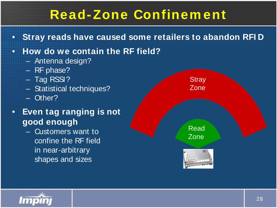
Read-Zone Confinement
• Stray reads have caused some retailers to abandon RFID
• How do we contain the RF field?– Antenna design?– RF phase?– Tag RSSI?– Statistical techniques?– Other?
• Even tag ranging is not good enough– Customers want to
confine the RF field in near-arbitrary shapes and sizes
Stray Zone
Read Zone
29
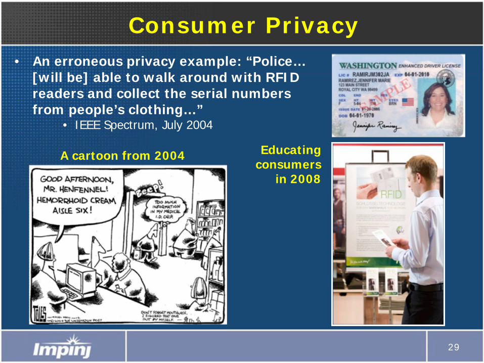
Consumer Privacy• An erroneous privacy example: “Police…
[will be] able to walk around with RFID readers and collect the serial numbers from people’s clothing…”
• IEEE Spectrum, July 2004
A cartoon from 2004 Educating consumers
in 2008
30
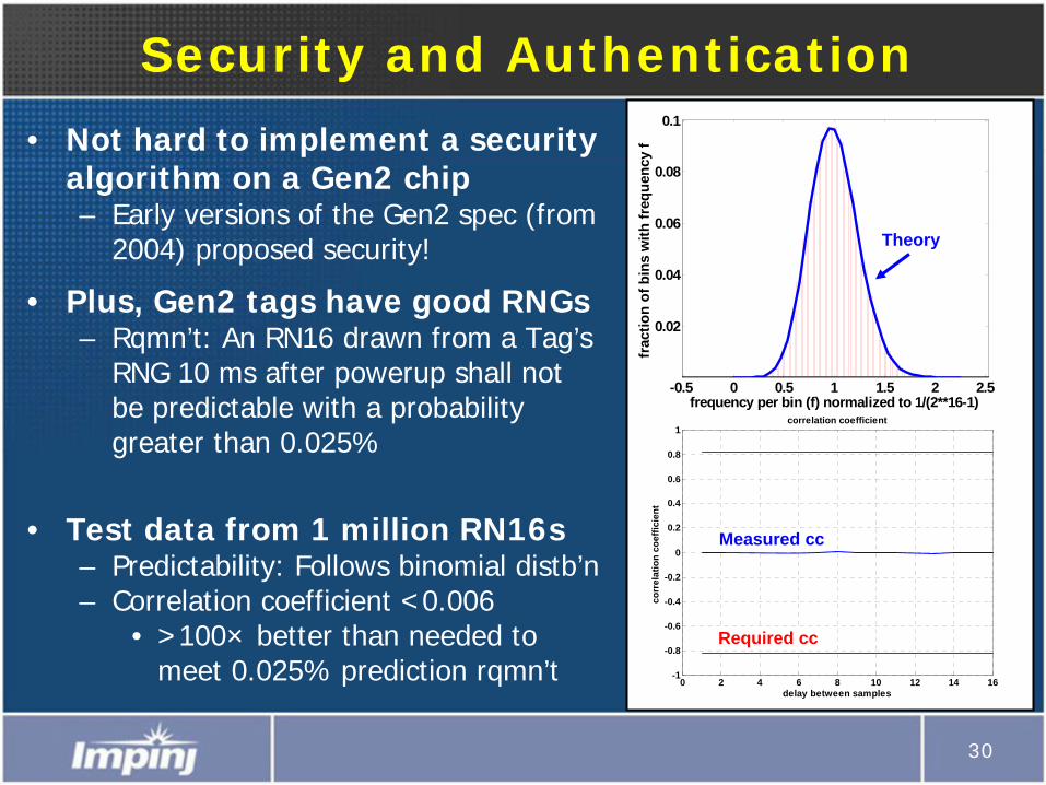
Security and Authentication
• Not hard to implement a security algorithm on a Gen2 chip– Early versions of the Gen2 spec (from
2004) proposed security!
• Plus, Gen2 tags have good RNGs– Rqmn’t: An RN16 drawn from a Tag’s
RNG 10 ms after powerup shall not be predictable with a probability greater than 0.025%
• Test data from 1 million RN16s– Predictability: Follows binomial distb’n– Correlation coefficient <0.006
• >100× better than needed to meet 0.025% prediction rqmn’t
-0.5 0 0.5 1 1.5 2 2.5
0.02
0.04
0.06
0.08
0.1
frac
tion
of b
ins
with
freq
uenc
y f
frequency per bin (f) normalized to 1/(2**16-1)
Theory
0 2 4 6 8 10 12 14 16-1
-0.8
-0.6
-0.4
-0.2
0
0.2
0.4
0.6
0.8
1correlation coefficient
delay between samples
corr
elat
ion
coef
ficie
nt
Measured cc
Required cc
31
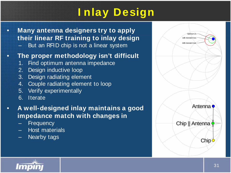
Inlay Design
• Many antenna designers try to apply their linear RF training to inlay design– But an RFID chip is not a linear system
• The proper methodology isn’t difficult1. Find optimum antenna impedance2. Design inductive loop3. Design radiating element4. Couple radiating element to loop5. Verify experimentally6. Iterate
• A well-designed inlay maintains a good impedance match with changes in– Frequency– Host materials– Nearby tags
Antenna
Chip
Chip || Antenna
Optimum Zs
1dB mismatch loss
2dB mismatch loss
32
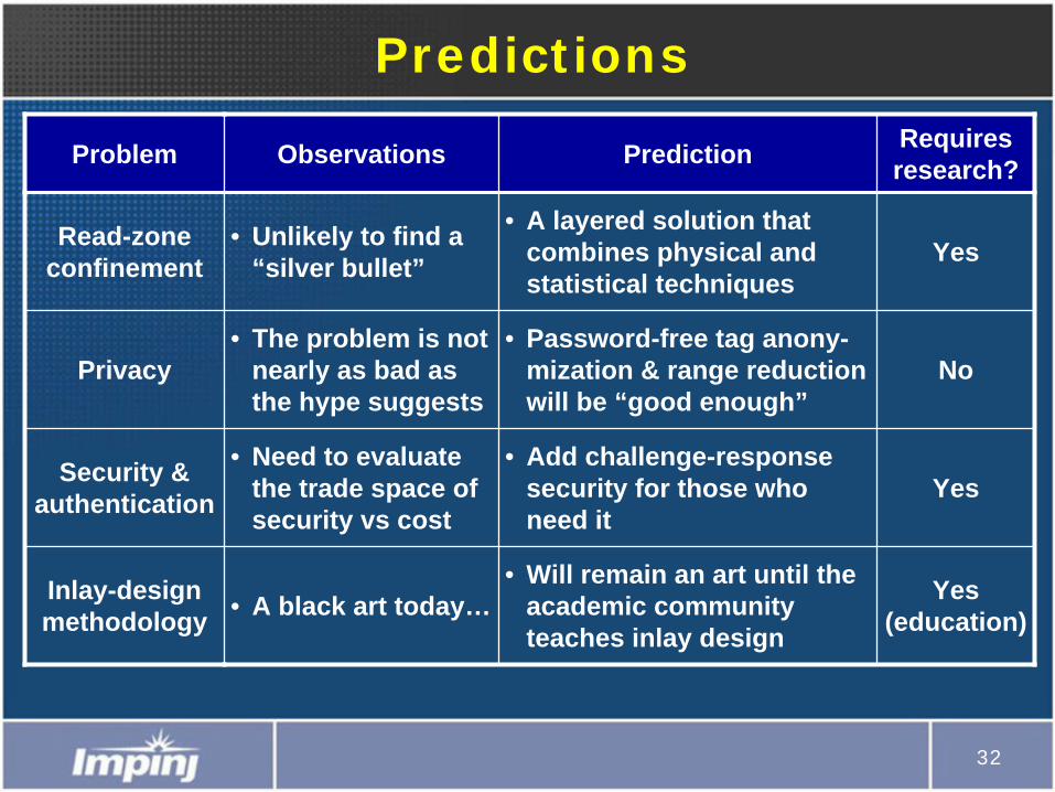
Predictions
Problem Observations Prediction Requires research?
Read-zone confinement
• Unlikely to find a “silver bullet”
• A layered solution that combines physical and statistical techniques
Yes
Privacy• The problem is not
nearly as bad as the hype suggests
• Password-free tag anony- mization & range reduction will be “good enough”
No
Security & authentication
• Need to evaluate the trade space of security vs cost
• Add challenge-response security for those who need it
Yes
Inlay-design methodology • A black art today…
• Will remain an art until the academic community teaches inlay design
Yes (education)