ubee interactive docsis 3.0 cable modem · (qpsk/ 8qam /16qam/ 32qam/64qam/128qam/256qam). symbol...
TRANSCRIPT

Ubee Interactive
DOCSIS 3.0 Cable Modem
Model# U10C035
User Guide
Rev. 1.2
February 2nd, 2009
2
Contents 1 BEFORE YOU BEGIN ............................................................................................................................................ 3
1.1 FEATURES ............................................................................................................................................................. 3
1.2 MINIMUM REQUIREMENTS .................................................................................................................................... 4
PC - Minimum Computer Specification ................................................................................................................. 4
Apple Mac - Minimum Computer Specification ..................................................................................................... 4
2 CABLE MODEM LEDS AND CONNECTORS .................................................................................................... 5
2.1 LEDS ON THE FRONT PANEL ................................................................................................................................. 5
2.2 REAR PANEL ......................................................................................................................................................... 7
WEB-BASED MANAGEMENT UTILITY ............................................................................................................... 8
2.3 PC REQUIREMENTS ............................................................................................................................................... 8
2.4 LOGGING IN .......................................................................................................................................................... 8
2.5 CABLE MODEM PAGE .......................................................................................................................................... 10
2.5.1 Information ..................................................................................................................................................11
2.5.2 Status........................................................................................................................................................... 12
2.5.3 Downstream ................................................................................................................................................ 13
2.5.4 Upstream ..................................................................................................................................................... 14
2.5.5 Upstream Burst ........................................................................................................................................... 15
2.5.6 Event Log .................................................................................................................................................... 16
2.6 TOOL PAGE.......................................................................................................................................................... 17
2.6.1 Reset Modem ............................................................................................................................................... 17
2.6.2 Factory Default Reset ................................................................................................................................. 18

3
1 Before You Begin
Your new cable modem provides high-speed access to the Internet by an active Internet connection
through your cable service provider. This user guide describes how to set up and use the cable modem.
Before installing the cable modem, you should read this user guide to ensure proper cable modem
operation.
1.1 Features
Your cable modem has the following features to help you access the Internet:
Two-way design allows the cable modem to send and receive data over the cable television
network.
Cable bandwidth allows data rates of up to 160 megabits per second (Mbps)*, which is faster than
traditional DOCSIS 2.0 cable modems, integrated services digital network (ISDN), or asymmetric
digital subscriber line (ADSL).
Using your cable line means that the cable modem is always on, always connected, and does not
tie up your phone line.
Data Over Cable Service Interface Specification (DOCSIS) compliance ensures interoperability
with DOCSIS compliant cable operators.
*NOTE: The following causes may affect the connection speed.
Computer specification, including available RAM space and processor speed.
Software applications that may be using computer’s resources.
Network traffic depending on the time of day.
Limitations set by your Cable Service Provider.
4
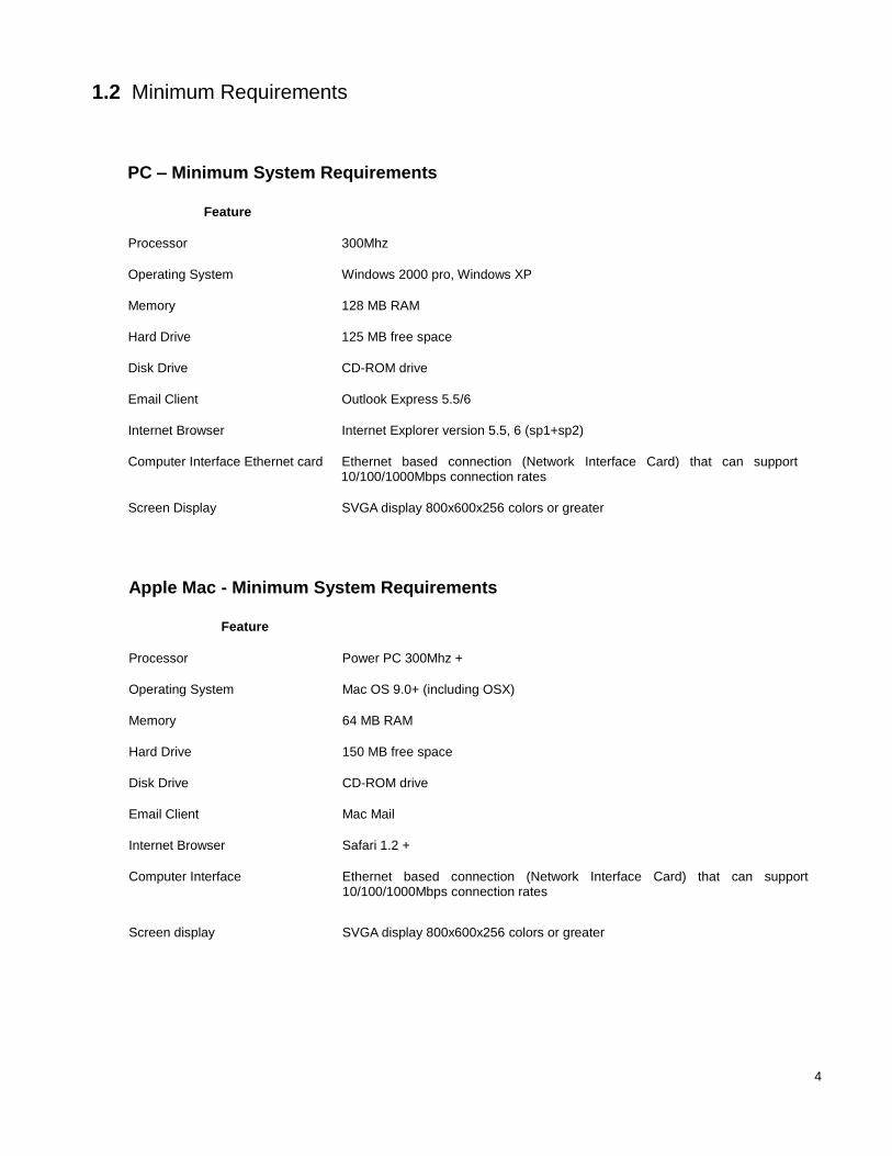
1.2 Minimum Requirements
PC – Minimum System Requirements
Feature
Processor 300Mhz
Operating System Windows 2000 pro, Windows XP
Memory 128 MB RAM
Hard Drive 125 MB free space
Disk Drive CD-ROM drive
Email Client Outlook Express 5.5/6
Internet Browser Internet Explorer version 5.5, 6 (sp1+sp2)
Computer Interface Ethernet card Ethernet based connection (Network Interface Card) that can support 10/100/1000Mbps connection rates
Screen Display SVGA display 800x600x256 colors or greater
Apple Mac - Minimum System Requirements
Feature
Processor Power PC 300Mhz +
Operating System Mac OS 9.0+ (including OSX)
Memory 64 MB RAM
Hard Drive 150 MB free space
Disk Drive CD-ROM drive
Email Client Mac Mail
Internet Browser Safari 1.2 +
Computer Interface Ethernet based connection (Network Interface Card) that can support 10/100/1000Mbps connection rates
Screen display SVGA display 800x600x256 colors or greater
5
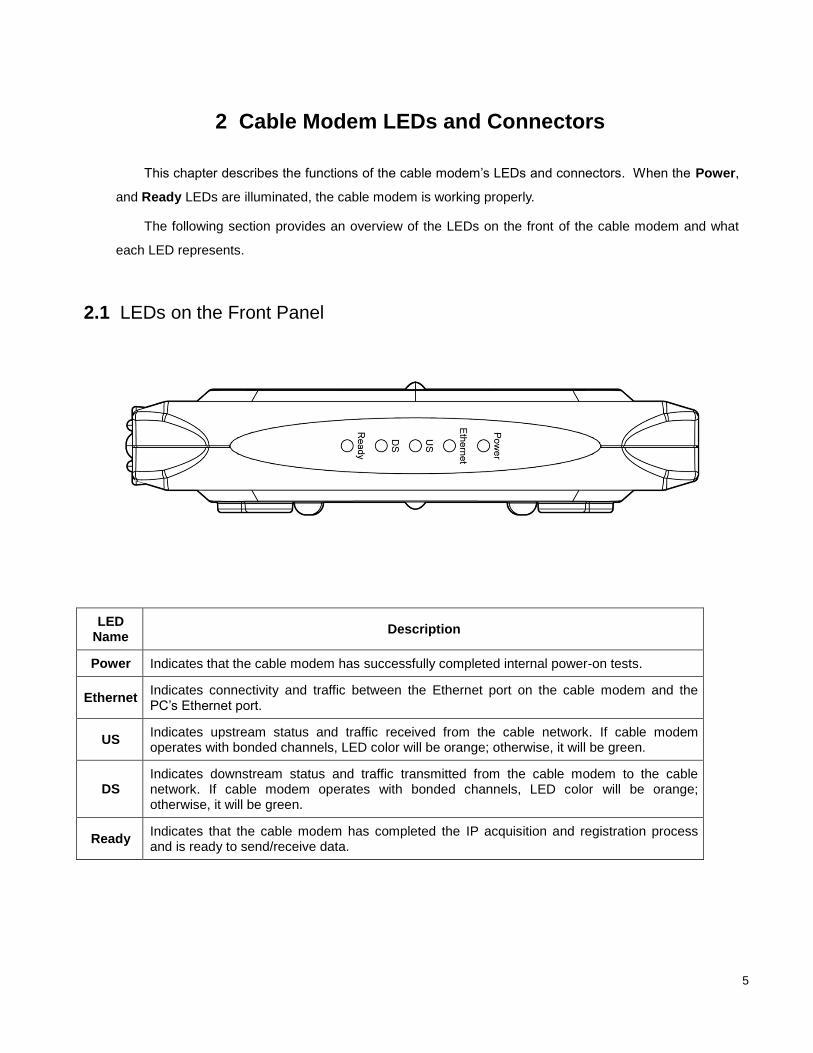
2 Cable Modem LEDs and Connectors
This chapter describes the functions of the cable modem’s LEDs and connectors. When the Power,
and Ready LEDs are illuminated, the cable modem is working properly.
The following section provides an overview of the LEDs on the front of the cable modem and what
each LED represents.
2.1 LEDs on the Front Panel
LED Name
Description
Power Indicates that the cable modem has successfully completed internal power-on tests.
Ethernet Indicates connectivity and traffic between the Ethernet port on the cable modem and the PC’s Ethernet port.
US Indicates upstream status and traffic received from the cable network. If cable modem operates with bonded channels, LED color will be orange; otherwise, it will be green.
DS Indicates downstream status and traffic transmitted from the cable modem to the cable network. If cable modem operates with bonded channels, LED color will be orange; otherwise, it will be green.
Ready Indicates that the cable modem has completed the IP acquisition and registration process and is ready to send/receive data.

6
Installation problems with the cable modem are commonly due to the cable network and its topology. LEDs on
the front panel of the cable modem reveal operational status and help you determine problem areas.
LED Name Provisioning State
Ready DS US
Ethernet Power single bonded single bonded
Driver init off off off off on
DS scanning off blink off
depends
on
Ethernet
status
on
DS locked off on off on
US ranging off on blink on
US ranged off on on on
IP Init & Registration blink on on on
Operational
Network Access Enabled
on on on on on on
Network Access Disabled
off on on on on on
LED Name
Interface Status Ready
DS US Ethernet Power
single bonded single bonded
Cable interface traffic (network access enabled)
on on on on on
depends
on
Ethernet
status
on
Ethernet connected depends on provisioning state on on
Ethernet traffic depends on provisioning state blink on
7
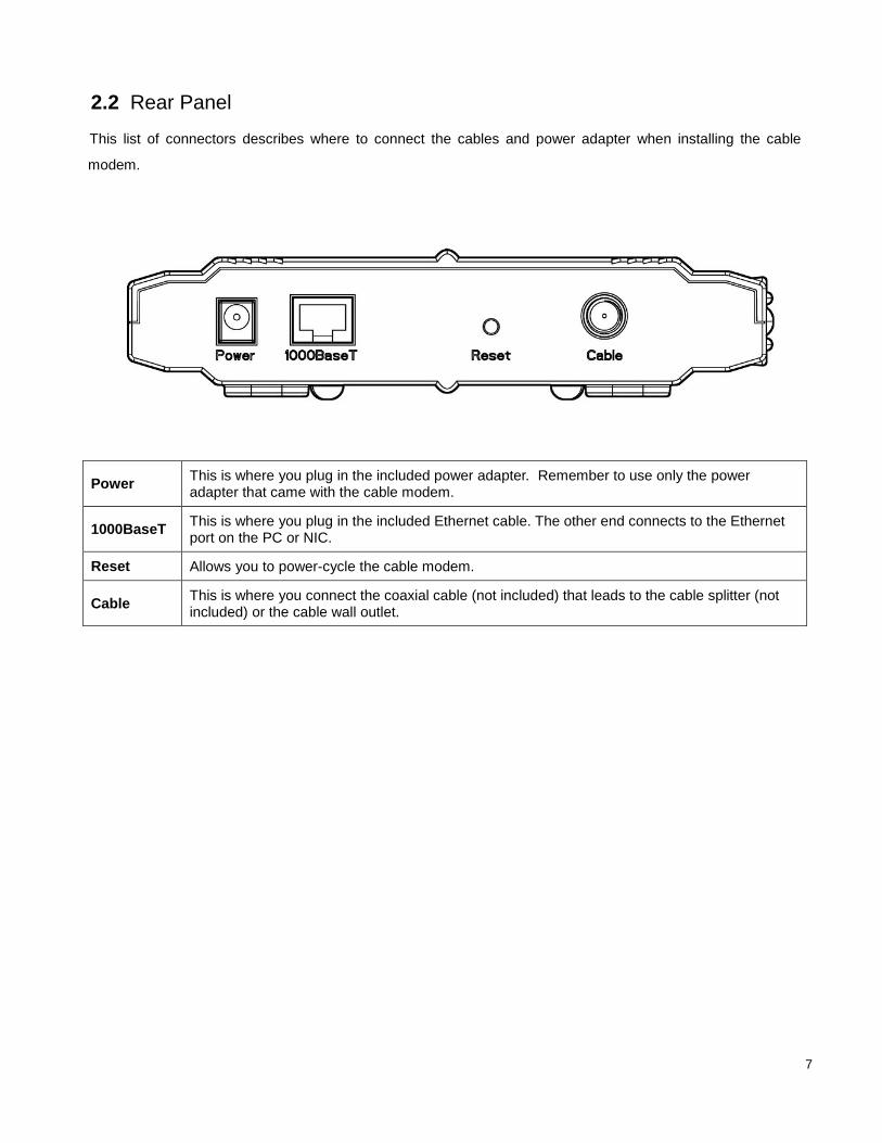
2.2 Rear Panel
This list of connectors describes where to connect the cables and power adapter when installing the cable
modem.
Power This is where you plug in the included power adapter. Remember to use only the power adapter that came with the cable modem.
1000BaseT This is where you plug in the included Ethernet cable. The other end connects to the Ethernet port on the PC or NIC.
Reset Allows you to power-cycle the cable modem.
Cable This is where you connect the coaxial cable (not included) that leads to the cable splitter (not included) or the cable wall outlet.

8
Web-Based Management Utility
By visiting the Web-based Management, you can see status information on the cable modem.
2.3 PC Requirements
Supporting TCP/IP
Supporting DHCP
Web browser
2.4 Logging In
Follow the steps below to access the Web-based management utility.
1) Start the web browser and go to http://192.168.100.1. You may also access using the cable/RF IP
address
Greeting Window
9
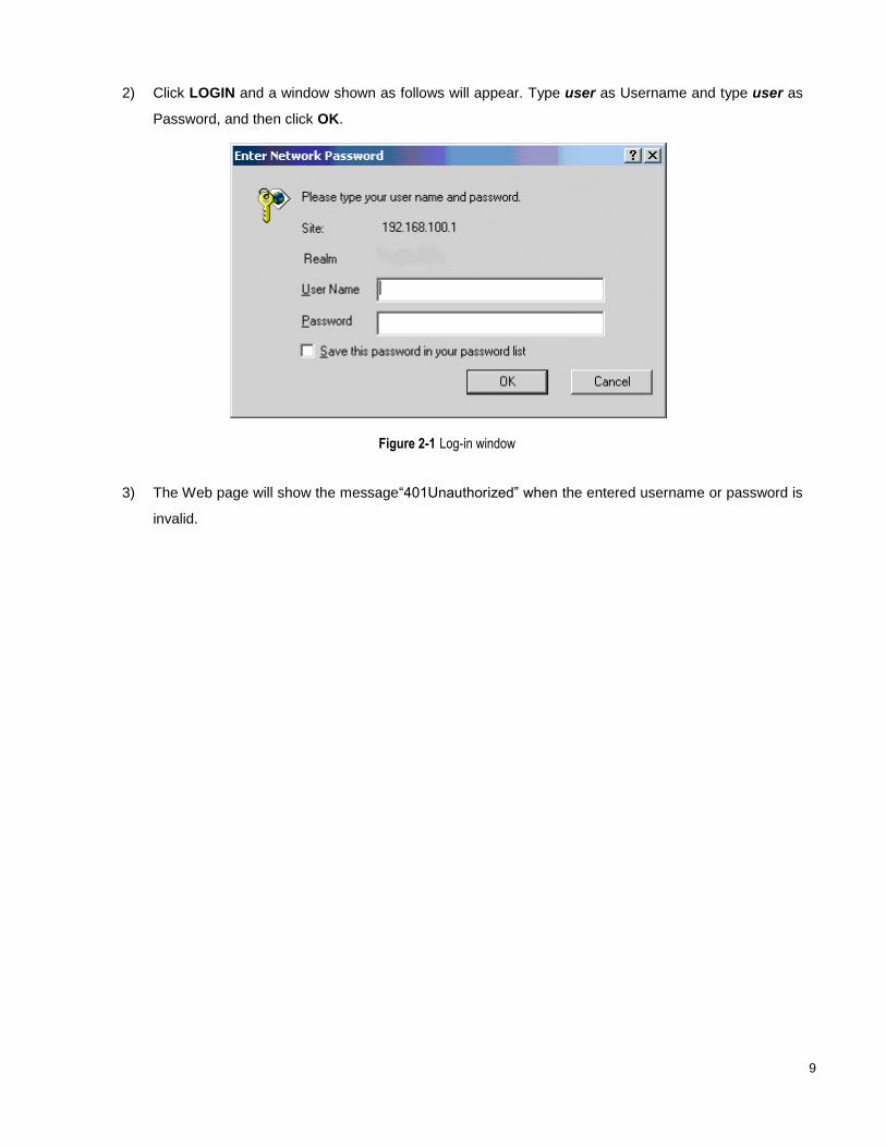
2) Click LOGIN and a window shown as follows will appear. Type user as Username and type user as
Password, and then click OK.
Figure 2-1 Log-in window
3) The Web page will show the message“401Unauthorized” when the entered username or password is
invalid.

10
2.5 Cable Modem Page
After you log in successfully, the following will be the first page you have access to as displayed in Figure
2-2. One hyperlink in the top right corner are the main menus. The respective sub-menus will be listed on the
left-hand side of the page.
Figure 2-2 Home page of the Web-based management utility.
Cable Modem page contains six sub-pages: Information, Status, Downstream, Upstream, Upstream Burst,
and Event Log.
11
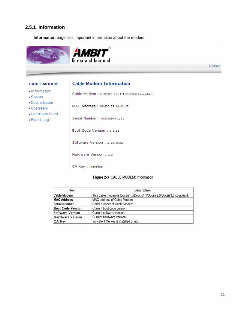
2.5.1 Information
Information page lists important information about the modem.
Figure 2-3 CABLE MODEM: Information
Item Description
Cable Modem This cable modem is Docsis1.0/Docsis1.1/Docsis2.0/Docsis3.0 compliant.
MAC Address MAC address of Cable Modem
Serial Number Serial number of Cable Modem
Boot Code Version Current boot code version.
Software Version Current software version.
Hardware Version Current hardware version.
CA Key Indicate if CA key is installed or not.

12
2.5.2 Status
Status page lists three items of the status of the modem. Click Refresh to obtain the latest information.
Figure 2-4 Status Page
Item Description
Acquired a Downstream Channel Current downstream lock status. (Status field will show downstream frequency. If comment field show “Locked”, cable modem already locked onto this frequency. Otherwise, it will show “In Progress”, cable modem is trying to lock onto a frequency).
Ranged Upstream Channel Current upstream ranging status. (Status field shows currently locked upstream frequency, and comments filed shows ranging status of locked upstream.)
Provisioning State Current cable modem state. (Status field show “Ok”, cable modem is operational. Otherwise, it will show “In Progress”, meaning the cable modem is in progress, and comments field will show current provisioning state).
Ethernet Link Status Current link status of the Ethernet interface. (Status field shows Up/Down to indicate if there are CPEs connected to the Ethernet interface, and comment field shows speed and duplex of connected CPEs.)

13
2.5.3 Downstream
Downstream page is shown as in Figure 2-5. Click Refresh to obtain the latest information.
Figure 2-5 Downstream page
Item Description
Frequency Current cable modem downstream frequency (Hz).
Lock Status (QAM Lock/FEC
Lock/MPEG Lock)
Current cable modem downstream lock status. It contains three sub-item, QAM Lock, FEC Lock, and MPEG Lock.
Channel ID Current locked downstream channel ID.
Modulation Current locked downstream modulation type (QAM64/ QAM256).
Symbol Rate (Msym/sec) Current locked downstream symbol rate (QAM64 is 5.056941 Msym/sec, QAM256 is 5.360537 Msym/sec).
Interleave Depth Current locked downstream interleaver characteristics. I means number of taps, and J means increment..
Power Level (dBmV) Current locked downstream received power (dBmV).
RxMER (dB) Current locked downstream Modulation Error Rate (MER).
Correctable Codewords This field shows R-S codewords received on this channel with correctable errors.
Uncorrectable Codewords This field shows R-S codewords received on this channel with uncorrectable errors.

14
2.5.4 Upstream
Figure 2-6 shows the page of Upstream. Click Refresh to obtain the latest information.
Figure 2-6 Upstream page
Item Description
Channel Type Current locked upstream channel type. It may be 1.0/2.0/mixed/3.0 according to collected UCDs.
Channel ID Current locked upstream channel identify.
Frequency (Hz) Current locked upstream frequency.
Ranging Status Current locked upstream ranging status. (Other/Aborted/Retries Exceed/Success/Continue/T4 Timeout)
Modulation Current locked upstream modulation type (QPSK/ 8QAM /16QAM/ 32QAM/64QAM/128QAM/256QAM).
Symbol Rate (Ksym/sec) Current locked upstream symbol rate
Mini-Slot Size Current locked upstream mini-slot.
Power Level (dBmV) Current locked upstream transmit power.
T1 Timeouts Wait for UCD timeout.
T2 Timeouts Wait for broadcast ranging timeout.
T3 Timeouts Wait for ranging response.
T4 Timeouts Wait for unicast ranging opportunity.

15
2.5.5 Upstream Burst
Figure 2-7 provides the Upstream Burst information. Click the Refresh button to obtain the latest
information.
Figure 2-7 Upstream Burst
Item Description
Modulation Type QPSK/16QAM/8QAM/32QAM/64QAM/128QAM.
Differential Encoding ON/OFF
Preamble Length 0-1536 (bits).
Preamble Value Offset 0-1534 (bits).
FEC Error Correction (T) 0 to 16 (0 implies no FEC. The number of codeword parity bytes is 2*T)
FEC Codeword Information Bytes (k) Fixed: 16 to 253 (assuming FEC on). Shortened: 16 to 253 (assuming FEC on)
Maximum Burst Size 0-255 (mini-slots)
Guard Time Size 4-255 (symbols)
Last Codeword Length FIX/SHORT
Scrambler on/off ON/OFF

16
2.5.6 Event Log
Figure 2-8 is the Event Log page.
Figure 2-8 Event log page
Item Description
Refresh Update result.
Clear Log Empty event log.
17
2.6 Tool Page
After you have logged in successfully, you may choose the MODEM or TOOL link located in the upper
right hand corner. The tool link will allow you to reset/power cycle the modem or perform a factory default..
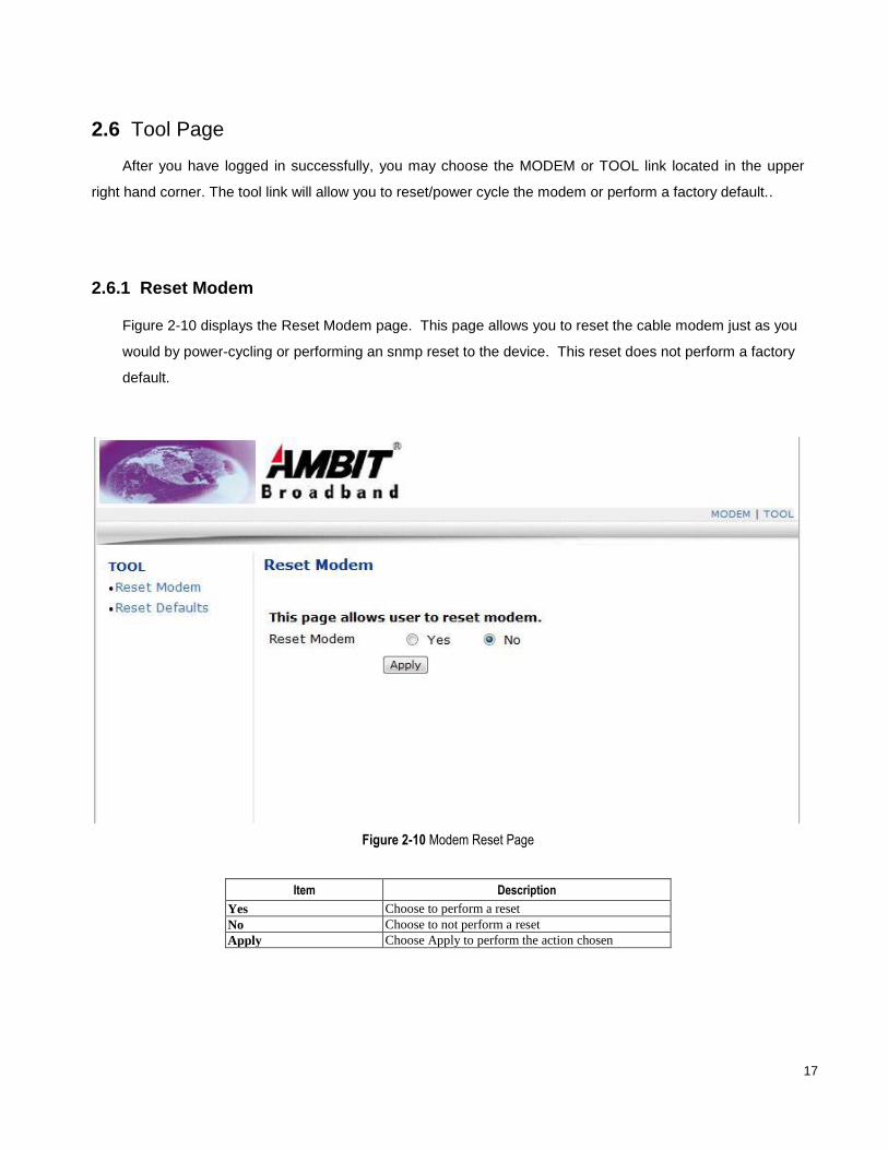
2.6.1 Reset Modem
Figure 2-10 displays the Reset Modem page. This page allows you to reset the cable modem just as you
would by power-cycling or performing an snmp reset to the device. This reset does not perform a factory
default.
Figure 2-10 Modem Reset Page
Item Description
Yes Choose to perform a reset
No Choose to not perform a reset
Apply Choose Apply to perform the action chosen
18
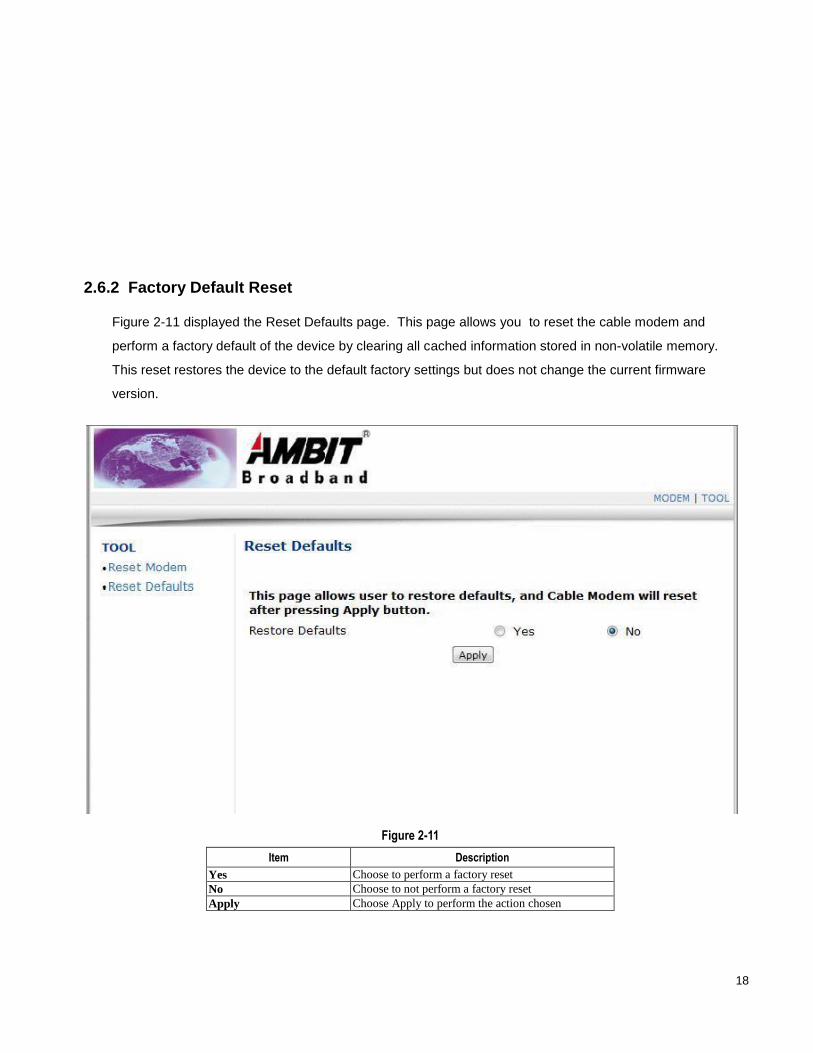
2.6.2 Factory Default Reset
Figure 2-11 displayed the Reset Defaults page. This page allows you to reset the cable modem and
perform a factory default of the device by clearing all cached information stored in non-volatile memory.
This reset restores the device to the default factory settings but does not change the current firmware
version.
Figure 2-11
Item Description
Yes Choose to perform a factory reset
No Choose to not perform a factory reset
Apply Choose Apply to perform the action chosen
19
====================================================================================
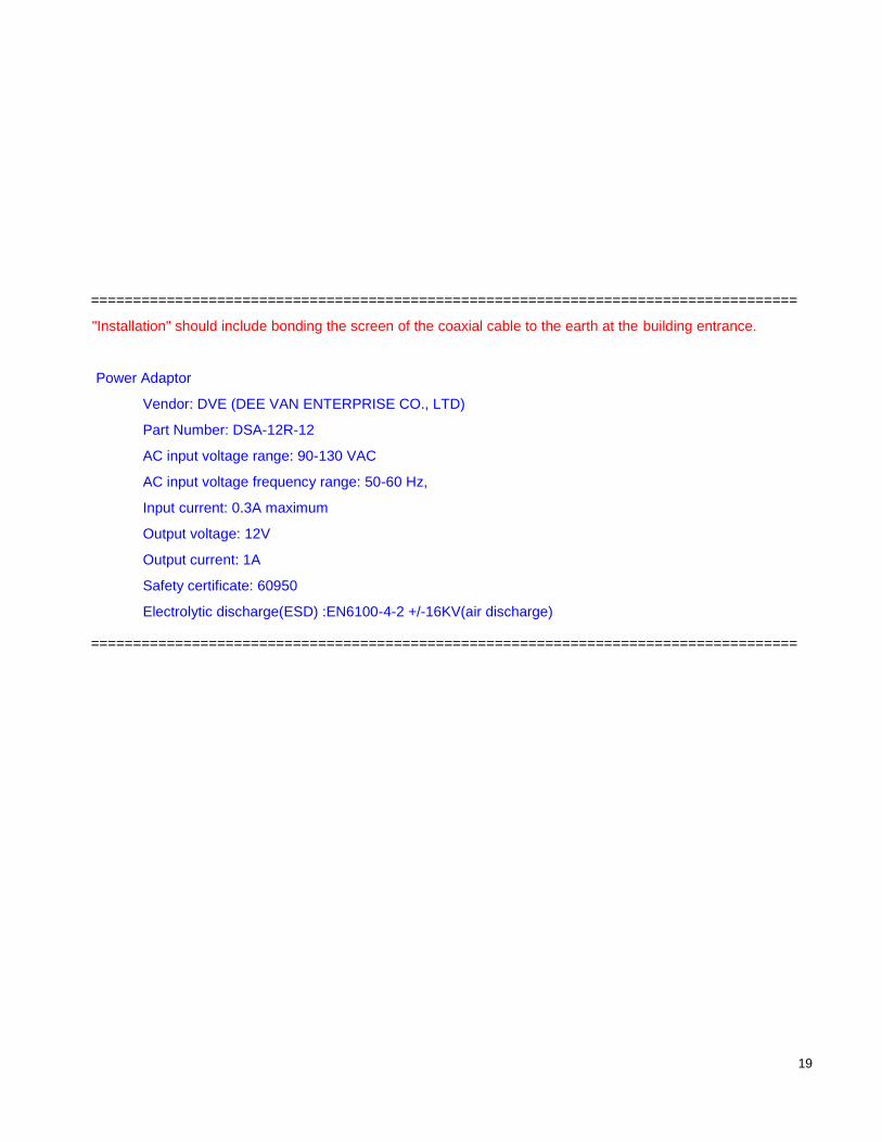
"Installation" should include bonding the screen of the coaxial cable to the earth at the building entrance.
Power Adaptor
Vendor: DVE (DEE VAN ENTERPRISE CO., LTD)
Part Number: DSA-12R-12
AC input voltage range: 90-130 VAC
AC input voltage frequency range: 50-60 Hz,
Input current: 0.3A maximum
Output voltage: 12V
Output current: 1A
Safety certificate: 60950
Electrolytic discharge(ESD) :EN6100-4-2 +/-16KV(air discharge)
====================================================================================