type certificate data sheet - easa.europa.eu · proprietary document. copies are not controlled....
TRANSCRIPT
TCDS No.: EASA.R.005 A109/A119
Issue: 20 Date: 20 June 2018
TE.CERT.00049-001 © European Aviation Safety Agency, 2018. All rights reserved. ISO9001 certified. Page 1 of 62 Proprietary document. Copies are not controlled. Confirm revision status through the EASA-Internet/Intranet.
An agency of the European Union
TYPE CERTIFICATE
DATA SHEET
No. EASA.R.005
for
A109/A119
Type Certificate Holder
Leonardo S.p.A.
Helicopters
Piazza Monte Grappa 4
00195 Roma
Italy
For Models: A109, A109A, A109AII, A109C, A109E, A109K2, A109LUH, A109N, A109S, AW109SP, A119, AW119MKII
TCDS No.: EASA.R.005 A109/A119
Issue: 20 Date: 20 June 2018
TE.CERT.00049-001 © European Aviation Safety Agency, 2018. All rights reserved. ISO9001 certified. Page 2 of 62 Proprietary document. Copies are not controlled. Confirm revision status through the EASA-Internet/Intranet.
An agency of the European Union
TABLE OF CONTENTS SECTION 1: A109 ............................................................................................................................................. 4
I. General ..................................................................................................................................................... 4
II. Certification Basis .................................................................................................................................... 4
III. Technical Characteristics and Operational Limitations ............................................................................ 4
IV. Operating and Service Instructions ......................................................................................................... 7
V. Notes ....................................................................................................................................................... 7
SECTION 2: A109A ........................................................................................................................................... 8
I. General ..................................................................................................................................................... 8
II. Certification Basis .................................................................................................................................... 8
III. Technical Characteristics and Operational Limitations ............................................................................ 9
IV. Operating and Service Instructions ....................................................................................................... 11
V. Notes ..................................................................................................................................................... 11
SECTION 3: A109AII ....................................................................................................................................... 12
I. General ................................................................................................................................................... 12
II. Certification Basis .................................................................................................................................. 12
III. Technical Characteristics and Operational Limitations .......................................................................... 13
IV. Operating and Service Instructions ....................................................................................................... 15
V. Notes ..................................................................................................................................................... 15
SECTION 4: A109C .......................................................................................................................................... 16
I. General ................................................................................................................................................... 16
II. Certification Basis .................................................................................................................................. 16
III. Technical Characteristics and Operational Limitations .......................................................................... 17
IV. Operating and Service Instructions ....................................................................................................... 19
V. Notes ..................................................................................................................................................... 19
SECTION 5: A109K2 ....................................................................................................................................... 20
I. General ................................................................................................................................................... 20
II. Certification Basis .................................................................................................................................. 20
III. Technical Characteristics and Operational Limitations .......................................................................... 21
IV. Operating and Service Instructions ....................................................................................................... 24
V. Notes ..................................................................................................................................................... 24
SECTION 6: A109E .......................................................................................................................................... 25
I. General ................................................................................................................................................... 25
II. Certification Basis .................................................................................................................................. 25
III. Technical Characteristics and Operational Limitations .......................................................................... 26
IV. Operating and Service Instructions ....................................................................................................... 30
V. Notes ..................................................................................................................................................... 30
SECTION 7: A119 ........................................................................................................................................... 31
I. General ................................................................................................................................................... 31
II. Certification Basis .................................................................................................................................. 31
III. Technical Characteristics and Operational Limitations .......................................................................... 32
IV. Operating and Service Instructions ....................................................................................................... 34
V. Notes ..................................................................................................................................................... 34
SECTION 8: A109LUH ...................................................................................................................................... 36
I. General ................................................................................................................................................... 36
II. Certification Basis .................................................................................................................................. 36
III. Technical Characteristics and Operational Limitations .......................................................................... 37
IV. Operating and Service Instructions ....................................................................................................... 40
V. Notes ..................................................................................................................................................... 40
TCDS No.: EASA.R.005 A109/A119
Issue: 20 Date: 20 June 2018
TE.CERT.00049-001 © European Aviation Safety Agency, 2018. All rights reserved. ISO9001 certified. Page 3 of 62 Proprietary document. Copies are not controlled. Confirm revision status through the EASA-Internet/Intranet.
An agency of the European Union
SECTION 9: A109S .......................................................................................................................................... 41
I. General ................................................................................................................................................... 41
II. Certification Basis .................................................................................................................................. 41
III. Technical Characteristics and Operational Limitations .......................................................................... 41
IV. Operating and Service Instructions ....................................................................................................... 45
V. Notes ..................................................................................................................................................... 45
SECTION 10: AW119MKII ............................................................................................................................... 46
I. General ................................................................................................................................................... 46
II. Certification Basis .................................................................................................................................. 46
III. Technical Characteristics and Operational Limitations .......................................................................... 47
IV. Operating and Service Instructions ....................................................................................................... 49
V. Notes ..................................................................................................................................................... 49
SECTION 11: AW109SP .................................................................................................................................. 50
I. General ................................................................................................................................................... 50
II. Certification Basis .................................................................................................................................. 50
III. Technical Characteristics and Operational Limitations .......................................................................... 50
IV. Operating and Service Instructions ....................................................................................................... 53
V. Notes ..................................................................................................................................................... 54
SECTION 12: A109N ....................................................................................................................................... 55
I. General ................................................................................................................................................... 55
II. Certification Basis .................................................................................................................................. 55
III. Technical Characteristics and Operational Limitations .......................................................................... 56
IV. Operating and Service Instructions ....................................................................................................... 58
V. Notes ..................................................................................................................................................... 58
SECTION 13: OPERATIONAL SUITABILITY DATA (OSD) .................................................................................... 59
I. OSD Certification Basis ........................................................................................................................... 59
II. OSD Elements ........................................................................................................................................ 59
SECTION: NOTES PERTINENT TO ALL MODELS ................................................................................................ 60
SECTION: ADMINISTRATIVE ............................................................................................................................ 61
I. Acronyms and Abbreviations .................................................................................................................. 61
II. Type Certificate Holder Record .............................................................................................................. 61
III. Change Record ...................................................................................................................................... 61
TCDS No.: EASA.R.005 A109/A119
Issue: 20 Date: 20 June 2018
TE.CERT.00049-001 © European Aviation Safety Agency, 2018. All rights reserved. ISO9001 certified. Page 4 of 62 Proprietary document. Copies are not controlled. Confirm revision status through the EASA-Internet/Intranet.
An agency of the European Union
SECTION 1: A109
I. General
1. Type/ Model/ Variant
1.1 Type A109
1.2 Model A109
1.3 Variant n/a
2. Airworthiness Category Small Rotorcraft
3. Manufacturer see “Section: Notes (Pertinent to all models)”, Note 3
4. Type Certification Application Date to RAI 18 February 1971
5. State of Design Authority EASA (pre EASA: RAI/ENAC, Italy)
6. Type Certificate Date by RAI 28 May 1975
7. Type Certificate n° by RAI SO/A 156
8. Type Certificate Data Sheet n° by RAI SO/A 156
9. EASA Type Certification Date 28 September 2003, in accordance with CR (EU) 1702/2003, Article 2, 3., (a), (i), 2nd bullet, 1st indented bullet.
II. Certification Basis
1. Reference Date for determining the applicable requirements
18 February 1971
2. Airworthiness Requirements FAR 27 / 29 Amdt. as defined here below. FAR 27 with Amdt. from 1 to 8 included, FAR 29 Paragraph 29.903 (b) “Category A, engine isolation”
3. Special Conditions Special Conditions N°27-54-EU-17 dated 26 June 1973 forwarded with sheet N° 109.489/T, dated 3 July 1973
4. Exemptions none
5. Deviations none
6. Equivalent Safety Findings Shut-off valve, instead of FAR 27.1189
7. Requirements elected to comply none
8. Environmental Protection Requirements
8.1 Noise see TCDSN EASA.R.005
8.2 Emissions n/a
9. Operational Suitability Data (OSD) Not required for rotorcraft that are no longer in production. CR (EU) 748/2012, as amended by CR (EU) 69/2014 does not require OSD elements for this model (see Article 7a, 1.).
III. Technical Characteristics and Operational Limitations
1. Type Design Definition Refer to Drawing 109-9000-01-5
2. Description Light twin-engine aircraft, four (4) metallic blades, articulated main rotor, twin (2) blades teetering tail rotor, tricycle retractable landing gear, one (1) pilot and seven (7) passengers capacity. (See Note 1 in this Section)
TCDS No.: EASA.R.005 A109/A119
Issue: 20 Date: 20 June 2018
TE.CERT.00049-001 © European Aviation Safety Agency, 2018. All rights reserved. ISO9001 certified. Page 5 of 62 Proprietary document. Copies are not controlled. Confirm revision status through the EASA-Internet/Intranet.
An agency of the European Union
3. Equipment Basic equipment required by the airworthiness rules (see Certification Basis) shall be installed on the helicopter for the Airworthiness Certificate release. Besides are required the following equipment: OAT Indicator P/N MS28028-1. Approved mandatory and optional equipment listed in report 109-07-01 “Elenco degli equipaggiamenti”. Refer also to the Equipment list in RFM
4. Dimensions
4.1 Fuselage Length: 10.71 m Width: 2.88 m Height: 3.30 m
4.2 Main Rotor Diameter: 11.00 m
4.3 Tail Rotor Diameter: 2.03 m
5. Engine
5.1 Model Rolls–Royce Corporation (former: Allison) 2 x Model 250-C20
5.2 Type Certificate State of Design Engine TC/TCDS n°: FAA n°E4CE EASA TC/TCDS n°: EASA.IM.E.052
5.3 Limitations
5.3.1 Installed Engine Limitations and Transmission Torque Limits
Installed Engine Limits
AEO Take-Off (5 minutes) 346 shp, 113%
Maximum Continuous 346 shp, 113%
OEI Take-Off (5 minutes) 400 shp, 131%
Maximum Continuous 385 shp, 126%
See EASA approved Rotorcraft Flight Manual for TOT, N1 and transient
Transmission Torque Limits
See EASA approved Rotorcraft Flight Manual for information
5.3.2 Other Engine and Transmission Torque Limits
Refer to approved RFM
6. Fluids (Fuel/ Oil/ Additives)
6.1 Fuel For all temperatures: MIL-T-5624 type JP4, ASTM D-1655 Jet B For temperatures higher than -18°C (0°F): MIL-T-5624 Type JP5, ASTM D-1655 Jet A, ASTM D-1655 Jet A1 For detailed information refer to EASA approved RFM Section 1
6.2 Oil Engines: MIL-L-7808G Transmission: MIL-L-7808G For detailed information refer to EASA approved RFM Section 1
7. Fluid capacities
7.1 Fuel Total usable: 550.0 litres (Two tanks capacity of 275 litres each) Refer to approved RFM for unusable fuel
TCDS No.: EASA.R.005 A109/A119
Issue: 20 Date: 20 June 2018
TE.CERT.00049-001 © European Aviation Safety Agency, 2018. All rights reserved. ISO9001 certified. Page 6 of 62 Proprietary document. Copies are not controlled. Confirm revision status through the EASA-Internet/Intranet.
An agency of the European Union
7.2 Oil Engines: 7.7 litres each Transmission: 12.0 litres Refer to approved RFM for non-drainable lubricant
8. Air Speed Limitations VNE: 168 KIAS Refer to approved RFM for reduction in VNE with altitude and other speed limitations
9. Rotor Speed Limitations Power on (AEO): Maximum 100 % (385 rpm) Minimum 95 % (365 rpm) Power off: Maximum 110 % (424 rpm) Minimum 90 % (346 rpm) Refer to approved RFM Section 1 for detailed information
10. Maximum Operating Altitude and Temperature
10.1 Altitude 15 000 ft (4 572 m) Hp
10.2 Temperature Refer to approved RFM
11. Operating Limitations VFR day and night, non-icing conditions Additional limitations for TO and LDG refer to approved RFM Section 1
12. Maximum Mass 2 450 kg
13. Centre of Gravity Range Refer to approved RFM for C.G. envelope
14. Datum Longitudinal: the datum line (STA 0) is located at 1 835 mm forward of the front jack point. Lateral: the datum line (BL 0) is located at ±450 mm inboard of each of the two main jack points and it coincides with the helicopter longitudinal plane of symmetry. Refer to RFM Section 5 for detailed information
15. Levelling Means Plumb line from ceiling reference point to the index plate located on passengers compartment floor. Refer to Maintenance Manual.
16. Minimum Flight Crew One (1) pilot (right seat)
17. Maximum Passenger Seating Capacity Seven (7) passengers
18. Passenger Emergency Exit Two (2), one (1) on each side of the passenger cabin
19. Maximum Baggage/ Cargo Loads 150 kg at STA 4 920 mm or according to load distribution defined in RFM – Section 5 Max load on cargo compartment floor: 500 kg/m2 Max load on securing points of cargo compartment: 91 kg
20. Rotor Blade Control Movement MR (collective): min +4°40’ max +18°10’ TR: RH pedal -7° LH pedal +21° For rigging information refer to Maintenance Manual
21. Auxiliary Power Unit (APU) n/a
22. Life-limited Parts Refer to EASA approved A109 Maintenance Manual Chapter 04
23. Wheels and Tyres 360x135-6 tubeless
TCDS No.: EASA.R.005 A109/A119
Issue: 20 Date: 20 June 2018
TE.CERT.00049-001 © European Aviation Safety Agency, 2018. All rights reserved. ISO9001 certified. Page 7 of 62 Proprietary document. Copies are not controlled. Confirm revision status through the EASA-Internet/Intranet.
An agency of the European Union
IV. Operating and Service Instructions
1. Flight Manual A109 Rotorcraft Flight Manual, approval letter 123.391/T, dated 21 May 1975 and later approved revision
2. Maintenance Manual A109 Maintenance Manual
3. Service Letters and Service Bulletins As published by the Type Certificate Holder as per “Section: Notes (pertinent to all models)”, Note 3
4. Required Equipment Refer to approved RFM and related supplements for the approved mandatory and optional equipment
V. Notes
1. Helicopters A109 Model can be converted in helicopter A109A Model according to the requirements of the RAI approved “Istruzione Tecnica n. A 109-I”.
2. Manufacturer's eligible serial numbers: Assembly drawing 109-9000-01-5 from s/n 7106 to s/n 7109.
* * *

TCDS No.: EASA.R.005 A109/A119
Issue: 20 Date: 20 June 2018
TE.CERT.00049-001 © European Aviation Safety Agency, 2018. All rights reserved. ISO9001 certified. Page 8 of 62 Proprietary document. Copies are not controlled. Confirm revision status through the EASA-Internet/Intranet.
An agency of the European Union
SECTION 2: A109A
I. General
1. Type/ Model/ Variant
1.1 Type A109
1.2 Model A109A
1.3 Variant n/a
2. Airworthiness Category Small Rotorcraft
3. Manufacturer see “Section: Notes (Pertinent to all models)”, Note 3
4. Type Certification Application Date to RAI 17 September 1975
5. State of Design Authority EASA (pre EASA: RAI/ENAC, Italy)
6. Type Certificate Date by RAI 15 March 1976
7. Type Certificate n° by RAI SO/A 156
8. Type Certificate Data Sheet n° by RAI SO/A 156
9. EASA Type Certification Date 28 September 2003, in accordance with CR (EU) 1702/2003, Article 2, 3., (a), (i), 2nd bullet, 1st indented bullet.’
II. Certification Basis
1. Reference Date for determining the applicable requirements
17 September 1975
2. Airworthiness Requirements
FAR 27 / 29 Amdt. as defined here below. FAR 27 with Amdt. 1 to 8 included, FAR 29 Paragraph 29.903 (b) “Category A, engine isolation”. For the installation 109-0810-22 (all dashes approved) required for IFR (IMC) operations, with one or two pilots during day and night: “Airworthiness Criteria for Helicopter Instrument Flight”, dated 15 December 1978 (RAI/FAA document).
3. Special Conditions Special Conditions N°27-54-EU-17 dated 26 June 1973 forwarded with sheet N° 109.489/T, dated 3 July 1973
4. Exemptions none
5. Deviations none
6. Equivalent Safety Findings Shut-off valve, instead of FAR 27.1189 FAR 27.1305 (d), refuel quantity indicator for A109A up to s/n 7165
7. Requirements elected to comply none
8. Environmental Protection Requirements
8.1 Noise see TCDSN EASA.R.005
8.2 Emissions n/a
9. Operational Suitability Data (OSD) Not required for rotorcraft that are no longer in production. CR (EU) 748/2012, as amended by CR (EU) 69/2014 does not require OSD elements for this model (see Article 7a, 1.).
TCDS No.: EASA.R.005 A109/A119
Issue: 20 Date: 20 June 2018
TE.CERT.00049-001 © European Aviation Safety Agency, 2018. All rights reserved. ISO9001 certified. Page 9 of 62 Proprietary document. Copies are not controlled. Confirm revision status through the EASA-Internet/Intranet.
An agency of the European Union
III. Technical Characteristics and Operational Limitations
1. Type Design Definition Refer to Drawing 109-9000-01-11/-15/-19/-23/-27
2. Description Light twin-engine aircraft, four (4) metallic blades, articulated main rotor, twin (2) blades teetering tail rotor, tricycle retractable landing gear, one (1) pilot and seven (7) passengers capacity. The A109A differs from A109 model for the installation of Allison 250-C20B Turbo Engines.
3. Equipment
Basic equipment required by the airworthiness rules (see Certification Basis) shall be installed on the helicopter for the Airworthiness Certificate release. Besides are required the following equipment: - OAT indicator P/N MS28028-1 - Low rotor rpm and engine failure warning system according to drawing N° 109-0729-21 or 109-
0729-31 and 109-0729-22 - For IFR (IMC) operation with one or two pilots during day and night install IFR P/N 109-0810-22 (all
dashes approved) applicable to N.C. 7107, 7130 and subsequent. Approved mandatory and optional equipment listed in report 109-07-03 “Elenco degli equipaggiamenti”. Refer also to the Equipment list in RFM
4. Dimensions
4.1 Fuselage Length: 10.71 m Width: 2.88 m Height: 3.30 m
4.2 Main Rotor Diameter: 11.00 m
4.3 Tail Rotor Diameter: 2.03 m
5. Engine
5.1 Model Rolls–Royce Corporation (former: Allison) 2 x Model 250-C20B
5.2 Type Certificate State of Design Engine TC/TCDS n°: FAA n°E4CE EASA TC/TCDS n°: EASA.IM.E.052
5.3 Limitations
5.3.1 Installed Engine Limitations and Transmission Torque Limits
INSTALLED ENGINE LIMITS
AEO Take-Off (5 minutes) 346 shp, 113%
Maximum Continuous 346 shp, 113%
OEI Take-Off (5 minutes) 400 shp, 131%
Maximum Continuous 385 shp, 126%
See EASA approved Rotorcraft Flight Manuals for TOT, N1 and transient
TRANSMISSION TORQUE LIMITS
See EASA approved Rotorcraft Flight Manuals for information
5.3.2 Other Engine and Transmission Torque Limits
Refer to approved RFM
6. Fluids (Fuel/ Oil/ Additives)
6.1 Fuel For all temperatures: MIL-T-5624 type JP4, ASTM D-1655 Jet B For temperatures higher than -18°C (0°F): MIL-T-5624 Type JP5, ASTM D-1655 Jet A, ASTM D-1655 Jet A1
TCDS No.: EASA.R.005 A109/A119
Issue: 20 Date: 20 June 2018
TE.CERT.00049-001 © European Aviation Safety Agency, 2018. All rights reserved. ISO9001 certified. Page 10 of 62 Proprietary document. Copies are not controlled. Confirm revision status through the EASA-Internet/Intranet.
An agency of the European Union
For detailed information refer to EASA approved RFM Section 1
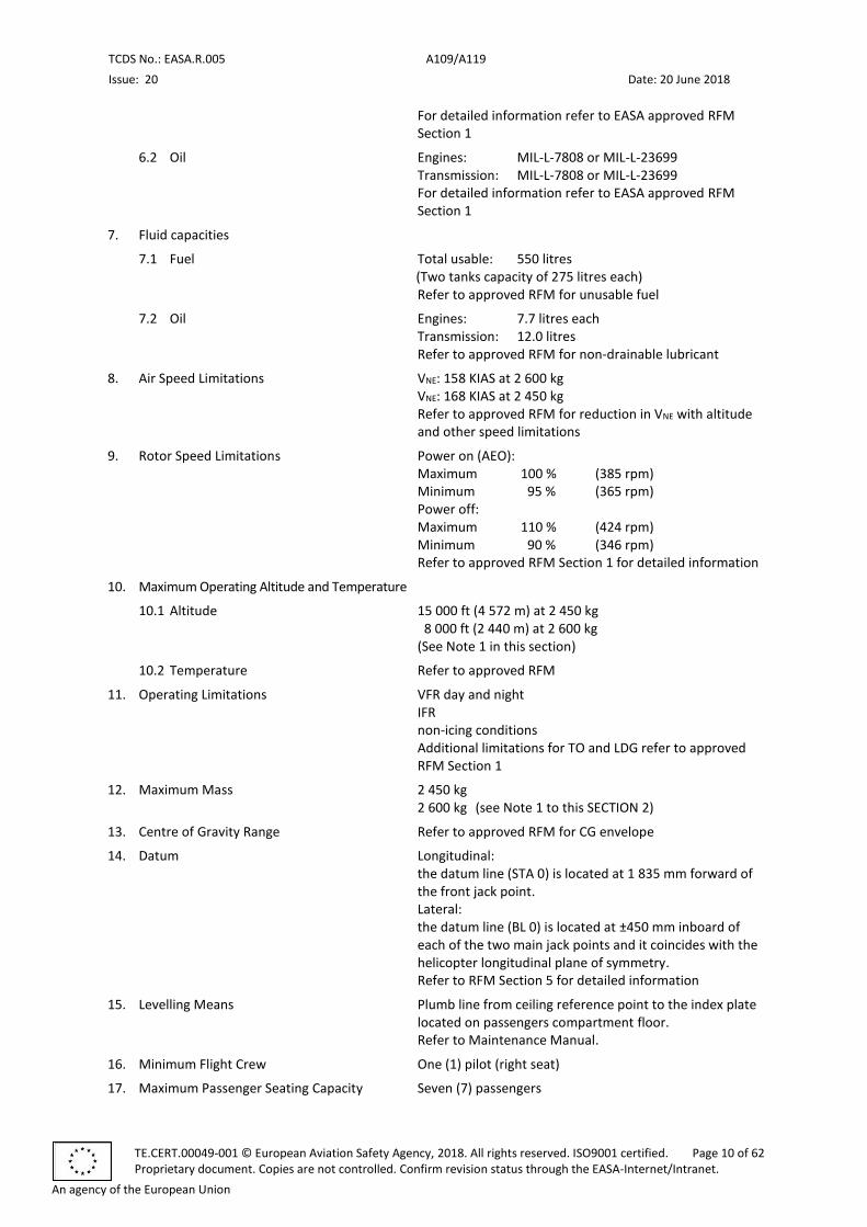
6.2 Oil Engines: MIL-L-7808 or MIL-L-23699 Transmission: MIL-L-7808 or MIL-L-23699 For detailed information refer to EASA approved RFM Section 1
7. Fluid capacities
7.1 Fuel Total usable: 550 litres (Two tanks capacity of 275 litres each) Refer to approved RFM for unusable fuel
7.2 Oil Engines: 7.7 litres each Transmission: 12.0 litres Refer to approved RFM for non-drainable lubricant
8. Air Speed Limitations VNE: 158 KIAS at 2 600 kg VNE: 168 KIAS at 2 450 kg Refer to approved RFM for reduction in VNE with altitude and other speed limitations
9. Rotor Speed Limitations Power on (AEO): Maximum 100 % (385 rpm) Minimum 95 % (365 rpm) Power off: Maximum 110 % (424 rpm) Minimum 90 % (346 rpm) Refer to approved RFM Section 1 for detailed information
10. Maximum Operating Altitude and Temperature
10.1 Altitude 15 000 ft (4 572 m) at 2 450 kg 8 000 ft (2 440 m) at 2 600 kg (See Note 1 in this section)
10.2 Temperature Refer to approved RFM
11. Operating Limitations VFR day and night IFR non-icing conditions Additional limitations for TO and LDG refer to approved RFM Section 1
12. Maximum Mass 2 450 kg 2 600 kg (see Note 1 to this SECTION 2)
13. Centre of Gravity Range Refer to approved RFM for CG envelope
14. Datum Longitudinal: the datum line (STA 0) is located at 1 835 mm forward of the front jack point. Lateral: the datum line (BL 0) is located at ±450 mm inboard of each of the two main jack points and it coincides with the helicopter longitudinal plane of symmetry. Refer to RFM Section 5 for detailed information
15. Levelling Means Plumb line from ceiling reference point to the index plate located on passengers compartment floor. Refer to Maintenance Manual.
16. Minimum Flight Crew One (1) pilot (right seat)
17. Maximum Passenger Seating Capacity Seven (7) passengers
TCDS No.: EASA.R.005 A109/A119
Issue: 20 Date: 20 June 2018
TE.CERT.00049-001 © European Aviation Safety Agency, 2018. All rights reserved. ISO9001 certified. Page 11 of 62 Proprietary document. Copies are not controlled. Confirm revision status through the EASA-Internet/Intranet.
An agency of the European Union
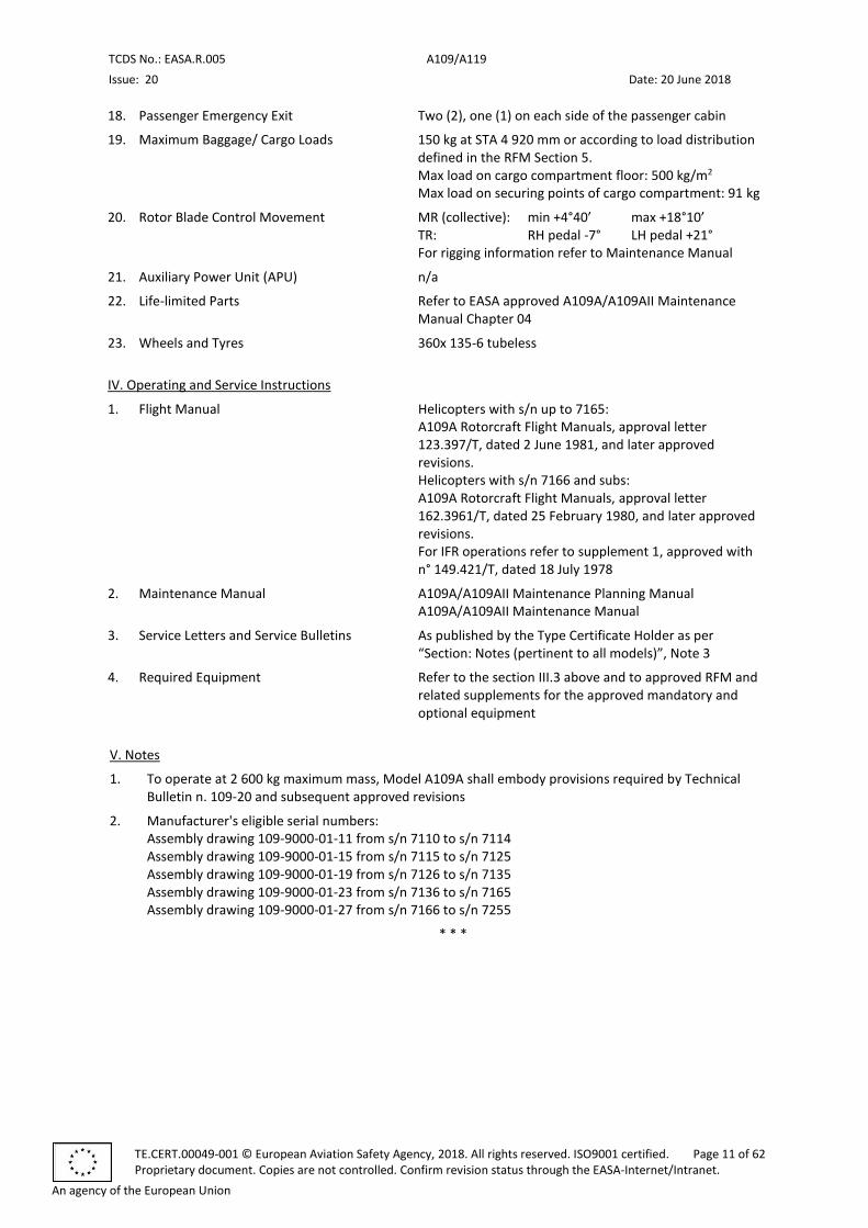
18. Passenger Emergency Exit Two (2), one (1) on each side of the passenger cabin
19. Maximum Baggage/ Cargo Loads 150 kg at STA 4 920 mm or according to load distribution defined in the RFM Section 5. Max load on cargo compartment floor: 500 kg/m2 Max load on securing points of cargo compartment: 91 kg
20. Rotor Blade Control Movement MR (collective): min +4°40’ max +18°10’ TR: RH pedal -7° LH pedal +21° For rigging information refer to Maintenance Manual
21. Auxiliary Power Unit (APU) n/a
22. Life-limited Parts Refer to EASA approved A109A/A109AII Maintenance Manual Chapter 04
23. Wheels and Tyres 360x 135-6 tubeless
IV. Operating and Service Instructions
1. Flight Manual Helicopters with s/n up to 7165: A109A Rotorcraft Flight Manuals, approval letter 123.397/T, dated 2 June 1981, and later approved revisions. Helicopters with s/n 7166 and subs: A109A Rotorcraft Flight Manuals, approval letter 162.3961/T, dated 25 February 1980, and later approved revisions. For IFR operations refer to supplement 1, approved with n° 149.421/T, dated 18 July 1978
2. Maintenance Manual A109A/A109AII Maintenance Planning Manual A109A/A109AII Maintenance Manual
3. Service Letters and Service Bulletins As published by the Type Certificate Holder as per “Section: Notes (pertinent to all models)”, Note 3
4. Required Equipment Refer to the section III.3 above and to approved RFM and related supplements for the approved mandatory and optional equipment
V. Notes
1. To operate at 2 600 kg maximum mass, Model A109A shall embody provisions required by Technical Bulletin n. 109-20 and subsequent approved revisions
2. Manufacturer's eligible serial numbers: Assembly drawing 109-9000-01-11 from s/n 7110 to s/n 7114 Assembly drawing 109-9000-01-15 from s/n 7115 to s/n 7125 Assembly drawing 109-9000-01-19 from s/n 7126 to s/n 7135 Assembly drawing 109-9000-01-23 from s/n 7136 to s/n 7165 Assembly drawing 109-9000-01-27 from s/n 7166 to s/n 7255
* * *
TCDS No.: EASA.R.005 A109/A119
Issue: 20 Date: 20 June 2018
TE.CERT.00049-001 © European Aviation Safety Agency, 2018. All rights reserved. ISO9001 certified. Page 12 of 62 Proprietary document. Copies are not controlled. Confirm revision status through the EASA-Internet/Intranet.
An agency of the European Union
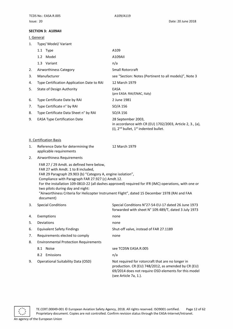
SECTION 3: A109AII
I. General
1. Type/ Model/ Variant
1.1 Type A109
1.2 Model A109AII
1.3 Variant n/a
2. Airworthiness Category Small Rotorcraft
3. Manufacturer see “Section: Notes (Pertinent to all models)”, Note 3
4. Type Certification Application Date to RAI 12 March 1979
5. State of Design Authority EASA (pre EASA: RAI/ENAC, Italy)
6. Type Certificate Date by RAI 2 June 1981
7. Type Certificate n° by RAI SO/A 156
8. Type Certificate Data Sheet n° by RAI SO/A 156
9. EASA Type Certification Date 28 September 2003, in accordance with CR (EU) 1702/2003, Article 2, 3., (a), (i), 2nd bullet, 1st indented bullet.
II. Certification Basis
1. Reference Date for determining the applicable requirements
12 March 1979
2. Airworthiness Requirements
FAR 27 / 29 Amdt. as defined here below, FAR 27 with Amdt. 1 to 8 included, FAR 29 Paragraph 29.903 (b) “Category A, engine isolation”, Compliance with Paragraph FAR 27.927 (c) Amdt.12. For the installation 109-0810-22 (all dashes approved) required for IFR (IMC) operations, with one or two pilots during day and night: “Airworthiness Criteria for Helicopter Instrument Flight”, dated 15 December 1978 (RAI and FAA document)
3. Special Conditions Special Conditions N°27-54-EU-17 dated 26 June 1973 forwarded with sheet N° 109.489/T, dated 3 July 1973
4. Exemptions none
5. Deviations none
6. Equivalent Safety Findings Shut-off valve, instead of FAR 27.1189
7. Requirements elected to comply none
8. Environmental Protection Requirements
8.1 Noise see TCDSN EASA.R.005
8.2 Emissions n/a
9. Operational Suitability Data (OSD) Not required for rotorcraft that are no longer in production. CR (EU) 748/2012, as amended by CR (EU) 69/2014 does not require OSD elements for this model (see Article 7a, 1.).
TCDS No.: EASA.R.005 A109/A119
Issue: 20 Date: 20 June 2018
TE.CERT.00049-001 © European Aviation Safety Agency, 2018. All rights reserved. ISO9001 certified. Page 13 of 62 Proprietary document. Copies are not controlled. Confirm revision status through the EASA-Internet/Intranet.
An agency of the European Union
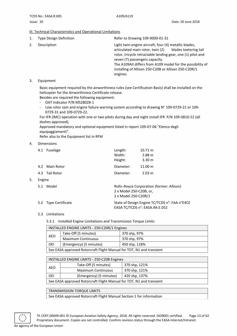
III. Technical Characteristics and Operational Limitations
1. Type Design Definition Refer to Drawing 109-9000-01-31
2. Description Light twin-engine aircraft, four (4) metallic blades, articulated main rotor, twin (2) blades teetering tail rotor, tricycle retractable landing gear, one (1) pilot and seven (7) passengers capacity. The A109AII differs from A109 model for the possibility of installing of Allison 250-C20B or Allison 250-C20R/1 engines
3. Equipment
Basic equipment required by the airworthiness rules (see Certification Basis) shall be installed on the helicopter for the Airworthiness Certificate release. Besides are required the following equipment: - OAT indicator P/N MS28028-1 - Low rotor rpm and engine failure warning system according to drawing N° 109-0729-21 or 109-
0729-31 and 109-0729-22. For IFR (IMC) operation with one or two pilots during day and night install IFR P/N 109-0810-22 (all dashes approved). Approved mandatory and optional equipment listed in report 109-07-06 “Elenco degli equipaggiamenti”. Refer also to the Equipment list in RFM
4. Dimensions
4.1 Fuselage Length: 10.71 m Width: 2.88 m Height: 3.30 m
4.2 Main Rotor Diameter: 11.00 m
4.3 Tail Rotor Diameter: 2.03 m
5. Engine
5.1 Model Rolls–Royce Corporation (former: Allison) 2 x Model 250-C20B, or, 2 x Model 250-C20R/1
5.2 Type Certificate State of Design Engine TC/TCDS n°: FAA n°E4CE EASA TC/TCDS n°: EASA.IM.E.052
5.3 Limitations
5.3.1 Installed Engine Limitations and Transmission Torque Limits
INSTALLED ENGINE LIMITS - 250-C20R/1 Engines
AEO Take-Off (5 minutes) 370 shp, 97%
Maximum Continuous 370 shp, 97%
OEI (Emergency) (5 minutes) 450 shp, 118%
See EASA approved Rotorcraft Flight Manual for TOT, N1 and transient
INSTALLED ENGINE LIMITS - 250-C20B Engines
AEO Take-Off (5 minutes) 370 shp, 121%
Maximum Continuous 370 shp, 121%
OEI (Emergency) (5 minutes) 420 shp, 137%
See EASA approved Rotorcraft Flight Manual for TOT, N1 and transient
TRANSMISSION TORQUE LIMITS
See EASA approved Rotorcraft Flight Manual Section 1 for information
TCDS No.: EASA.R.005 A109/A119
Issue: 20 Date: 20 June 2018
TE.CERT.00049-001 © European Aviation Safety Agency, 2018. All rights reserved. ISO9001 certified. Page 14 of 62 Proprietary document. Copies are not controlled. Confirm revision status through the EASA-Internet/Intranet.
An agency of the European Union
5.3.2 Other Engine and Transmission Torque Limits
Refer to approved RFM
6. Fluids (Fuel/ Oil/ Additives)
6.1 Fuel For all temperatures: MIL-T-5624 type JP4, ASTM D-1655 Jet B For temperatures higher than -18°C (0°F): MIL-T-5624 Type JP5, ASTM D-1655 Jet A, ASTM D-1655 Jet A1 For detailed information refer to approved RFM Section 1
6.2 Oil Engines: MIL-L-7808G and subsequent or MIL-L-23699 (for ambient temperature above -40°C) Transmission: MIL-L-7808 G and subsequent or MIL-L-23699 (for ambient temperature above -40°C) For detailed information see approved RFM Section 1.
7. Fluid capacities
7.1 Fuel Total usable: 550 litres (Two tanks capacity of 275 litres each) (Refer to approved RFM for unusable fuel)
7.2 Oil Engines: 7.7 litres each Transmission: 12.0 litres (Refer to approved RFM for non-drainable lubricant)
8. Air Speed Limitations VNE: 168 KIAS Refer to approved RFM for reduction in VNE with altitude and other speed limitations
9. Rotor Speed Limitations Power on (AEO): Maximum 100 % (385 rpm) Minimum 95 % (365 rpm) Power off: Maximum 110 % (424 rpm) Minimum 90 % (346 rpm) Refer to approved RFM Section 1 for detailed information
10. Maximum Operating Altitude and Temperature
10.1 Altitude 15 000 ft (4 572 m)
10.2 Temperature Refer to approved RFM
11. Operating Limitations VFR day and night IFR Non-icing conditions Additional limitations for TO and LDG refer to approved RFM Section 1
12. Maximum Mass 2 600 kg
13. Centre of Gravity Range Refer to approved RFM for CG envelope
14. Datum Longitudinal: the datum line (STA 0) is located at 1 835 mm forward of the front jack point. Lateral: the datum line (BL 0) is located at ±450 mm inboard of each of the two main jack points and it coincides with the helicopter longitudinal plane of symmetry. Refer to RFM Section 5 for detailed information
TCDS No.: EASA.R.005 A109/A119
Issue: 20 Date: 20 June 2018
TE.CERT.00049-001 © European Aviation Safety Agency, 2018. All rights reserved. ISO9001 certified. Page 15 of 62 Proprietary document. Copies are not controlled. Confirm revision status through the EASA-Internet/Intranet.
An agency of the European Union
15. Levelling Means Plumb line from ceiling reference point to the index plate located on passengers compartment floor. Refer to Maintenance Manual.
16. Minimum Flight Crew One (1) pilot (right seat)
17. Maximum Passenger Seating Capacity Seven (7) passengers
18. Passenger Emergency Exit Two (2), one (1) on each side of the passenger cabin
19. Maximum Baggage/ Cargo Loads 150 kg at STA 4 920 mm or according to load distribution defined in the RFM – Section 5. Max load on cargo compartment floor: 500 kg/m2 Max load on securing points of cargo compartment: 91 kg
20. Rotor Blade Control Movement MR (collective): min +4°40’ max +18°10’ TR: RH pedal -7° LH pedal +21° For rigging information refer to Maintenance Manual
21. Auxiliary Power Unit (APU) n/a
22. Life-limited Parts Refer to EASA approved A109A/A109AII Maintenance Manual Chapter 04
23. Wheels and Tyres 360x135-6 tubeless
IV. Operating and Service Instructions
1. Flight Manual A109AII Rotorcraft Flight Manual, approval letter n° 173.928/T of 2 June 1981,and later approved revisions
2. Maintenance Manual A109A/A109AII Maintenance Planning Manual A109A/A109AII Maintenance Manual
3. Service Letters and Service Bulletins As published by the Type Certificate Holder as per “Section: Notes (pertinent to all models)”, Note 3
4. Required Equipment Refer to the section III.3 above and to approved Rotorcraft Flight Manual and related supplements for the approved mandatory and optional equipment
V. Notes
1. Manufacturer's eligible serial numbers: Assembly drawing 109-9000-01-31 from s/n 7256 to s/n 7600
* * *

TCDS No.: EASA.R.005 A109/A119
Issue: 20 Date: 20 June 2018
TE.CERT.00049-001 © European Aviation Safety Agency, 2018. All rights reserved. ISO9001 certified. Page 16 of 62 Proprietary document. Copies are not controlled. Confirm revision status through the EASA-Internet/Intranet.
An agency of the European Union
SECTION 4: A109C
I. General
1. Type/ Model/ Variant
1.1 Type A109
1.2 Model A109C
1.3 Variant n/a
2. Airworthiness Category Small Rotorcraft
3. Manufacturer see “Section: Notes (Pertinent to all models)”, Note 3
4. Type Certification Application Date to RAI 14 May 1987
5. State of Design Authority EASA (pre EASA: RAI/ENAC, Italy)
6. Type Certificate Date by RAI 20 June 1989
7. Type Certificate n° by RAI SO/A 156
8. Type Certificate Data Sheet n° by RAI SO/A 156
9. EASA Type Certification Date 28 September 2003, in accordance with CR (EU) 1702/2003, Article 2, 3., (a), (i), 2nd bullet, 1st indented bullet.
II. Certification Basis
1. Reference Date for determining the applicable requirements
14 May 1987
2. Airworthiness Requirements
FAR 27 / 29 Amdt. as defined here below, FAR 27 with Amdt. 1 to 8 included, FAR 29 Paragraph 29.903 (b) “Category A; engine isolation” Compliance with Paragraph FAR 27.927 (c) Amdt.12. For the installation 109-0810-22 (all dashes approved) required for IFR (IMC) operations, with one or two pilots during day and night: “Airworthiness Criteria for Helicopter Instrument Flight” dated 15 December 1978 (RAI and FAA document)
3. Special Conditions Special Conditions N°27-54-EU-17, dated 26 June 1973 forwarded with sheet N° 109.489/T, dated 3 July 1973
4. Exemptions none
5. Deviations none
6. Equivalent Safety Findings Shut-off valve, instead of FAR 27.1189
7. Requirements elected to comply none
8. Environmental Protection Requirements
8.1 Noise see TCDSN EASA.R.005
8.2 Emissions n/a
9. Operational Suitability Data (OSD) Not required for rotorcraft that are no longer in production. CR (EU) 748/2012, as amended by CR (EU) 69/2014 does not require OSD elements for this model (see Article 7a, 1.).
TCDS No.: EASA.R.005 A109/A119
Issue: 20 Date: 20 June 2018
TE.CERT.00049-001 © European Aviation Safety Agency, 2018. All rights reserved. ISO9001 certified. Page 17 of 62 Proprietary document. Copies are not controlled. Confirm revision status through the EASA-Internet/Intranet.
An agency of the European Union
III. Technical Characteristics and Operational Limitations
1. Type Design Definition Refer to Drawing 109-9000-01-135
2. Description Light twin-engine aircraft, four (4) composite MR blades, articulated main rotor, twin (2) blades teetering tail rotor, tricycle retractable landing gear, one (1) pilot and seven (7) passengers capacity. The A109C differs from A109AII model for the installation of composite MR blades and increased maximum mass
3. Equipment
Basic equipment required by the airworthiness rules (see Certification Basis) shall be installed on the helicopter for the Airworthiness Certificate release. Besides are required the following equipment: - OAT indicator P/N MS28028-1. - Low rotor rpm and engine failure warning system according to drawing N° 109-0741-06. For IFR (IMC) operation with one or two pilots during day and night install IFR P/N 109-0810-22 (all dashes approved). Approved mandatory and optional equipment listed in report 109-07-09 “Elenco degli equipaggiamenti”. Refer also to the Equipment list in RFM
4. Dimensions
4.1 Fuselage Length: 11.45 m Width: 2.88 m Height: 3.50 m
4.2 Main Rotor Diameter: 11.00 m
4.3 Tail Rotor Diameter: 2.00 m
5. Engine
5.1 Model Rolls–Royce Corporation (former: Allison) 2 x Model 250-C20R/1
5.2 Type Certificate State of Design Engine TC/TCDS n°: FAA n°E4CE EASA TC/TCDS n°: EASA.IM.E.052
5.3 Limitations
5.3.1 Installed Engine Limitations and Transmission Torque Limits
INSTALLED ENGINE LIMITS
AEO Take Off 395 shp, 104%
Maximum Continuous 380 shp, 100%
OEI (Emergency) Maximum Continuous 450 shp, 118%
See EASA approved Rotorcraft Flight Manuals for TOT, N1 and transient
TRANSMISSION TORQUE LIMITS
See EASA approved Rotorcraft Flight Manual Section 1
5.3.2 Other Engine and Transmission Torque Limits
Refer to approved RFM
6. Fluids (Fuel/ Oil/ Additives)
6.1 Fuel For all temperatures: MIL-T-5624 type JP4, ASTM D-1655 Jet B For temperatures higher than -18°C (0°F): MIL-T-5624 Type JP5, ASTM D-1655 Jet A, ASTM D 1655 Jet A1
TCDS No.: EASA.R.005 A109/A119
Issue: 20 Date: 20 June 2018
TE.CERT.00049-001 © European Aviation Safety Agency, 2018. All rights reserved. ISO9001 certified. Page 18 of 62 Proprietary document. Copies are not controlled. Confirm revision status through the EASA-Internet/Intranet.
An agency of the European Union
For detailed information refer to EASA approved RFM Section 1
6.2 Oil Engines: MIL-L-7808G and subsequent or MIL-L-23699 (for ambient temperature above -40°C) Transmission: MIL-L-7808 G and subsequent or MIL-L-23699 (for ambient temperature above -40°C) For detailed information refer to EASA approved RFM Section 1
7. Fluid capacities
7.1 Fuel Total usable: 550 litres (Two tanks capacity of 275 litres each) (Refer to approved RFM for unusable fuel)
7.2 Oil Engines: 7.7 litres each Transmission: 12.0 litres (Refer to approved RFM for non-drainable lubricant)
8. Air Speed Limitations VNE: 168 KIAS Refer to approved RFM for reduction in VNE with altitude and other speed limitations
9. Rotor Speed Limitations Power on (AEO): Maximum 100 % (385 rpm) Minimum 95 % (365 rpm) Power off: Maximum 110 % (424 rpm) Minimum 90 % (346 rpm) Refer to approved RFM Section 1 for detailed information
10. Maximum Operating Altitude and Temperature
10.1 Altitude 15 000 ft (4 572 m)
10.2 Temperature Refer to approved RFM
11. Operating Limitations VFR day and night IFR non-icing conditions Additional limitations for TO and LDG refer to approved RFM Section 1
12. Maximum Mass 2 720 kg
13. Centre of Gravity Range Refer to approved RFM for CG envelope
14. Datum Longitudinal: the datum line (STA 0) is located at 1 835 mm forward of the front jack point. Lateral: the datum line (BL 0) is located at ±450 mm inboard of each of the two main jack points and it coincides with the helicopter longitudinal plane of symmetry. Refer to RFM Section 5 for detailed information
15. Levelling Means Plumb line from ceiling reference point to the index plate located on passengers compartment floor. Refer to Maintenance Manual.
16. Minimum Flight Crew One (1) pilot (right seat)
17. Maximum Passenger Seating Capacity Seven (7) passengers
18. Passenger Emergency Exit Two (2), one (1) on each side of the passenger cabin
TCDS No.: EASA.R.005 A109/A119
Issue: 20 Date: 20 June 2018
TE.CERT.00049-001 © European Aviation Safety Agency, 2018. All rights reserved. ISO9001 certified. Page 19 of 62 Proprietary document. Copies are not controlled. Confirm revision status through the EASA-Internet/Intranet.
An agency of the European Union
19. Maximum Baggage/ Cargo Loads 150 kg at STA 4 920 mm or according to load distribution defined in the RFM – Section 5. Max load on cargo compartment floor: 500 kg/m2 Max load on securing points of cargo compartment: 91 kg
20. Rotor Blade Control Movement MR (collective): min +4°40’ max +18°10’ TR: RH pedal -7° LH pedal +21° For rigging information refer to Maintenance Manual
21. Auxiliary Power Unit (APU) n/a
22. Life-limited Parts Refer to EASA approved A109C Maintenance Planning Manual Chapter 04
23. Wheels and Tyres 360x135-6 tubeless
IV. Operating and Service Instructions
1. Flight Manual A109C Rotorcraft Flight Manuals, approval letter 256.357/SCMA dated 19 June 1989,and later approved revisions.
2. Maintenance Manual A109C Maintenance Planning Manual A109C Maintenance Manual
3. Service Letters and Service Bulletins As published by the Type Certificate Holder as per “Section: Notes (pertinent to all models)”, Note 3
4. Required Equipment Refer to the section III.3 above and to approved Rotorcraft Flight Manuals and related supplements for the approved mandatory and optional equipment
V. Notes
1. Manufacturer's eligible serial numbers: Assembly drawing 109-9000-01-135 from s/n 7601 to s/n 7800
* * *
TCDS No.: EASA.R.005 A109/A119
Issue: 20 Date: 20 June 2018
TE.CERT.00049-001 © European Aviation Safety Agency, 2018. All rights reserved. ISO9001 certified. Page 20 of 62 Proprietary document. Copies are not controlled. Confirm revision status through the EASA-Internet/Intranet.
An agency of the European Union
SECTION 5: A109K2
I. General
1. Type/ Model/ Variant
1.1 Type A109
1.2 Model A109K2
1.3 Variant n/a
2. Airworthiness Category Small Rotorcraft Restricted Category (differs from A109K2 model for the installation of Kit P/N 109-0811-36 or of Kit P/N 109 0811-70 for E.M.S. operations).
3. Manufacturer see “Section: Notes (Pertinent to all models)”, Note 3
4. Type Certification Application Date to RAI Normal Category: 9 July 1984 Restricted Category: 4 March 1993
5. State of Design Authority EASA (pre EASA: RAI/ENAC, Italy)
6. Type Certificate Date by RAI Normal Category: 23 January 1992 Restricted Category: 7 July 1993
7. Type Certificate n° by RAI SO/A 156
8. Type Certificate Data Sheet n° by RAI SO/A 156
9. EASA Type Certification Date 28 September 2003, in accordance with CR (EU) 1702/2003, Article 2, 3., (a), (i), 2nd bullet, 1st indented bullet.
II. Certification Basis
1. Reference Date for determining the applicable requirements
Normal Category: 9 July 1984 Restricted Category: 4 March 1993
2. Airworthiness Requirements
Normal Category and Restricted Category: FAR 27 / 29, JAR 29 Amdt. as defined here below, FAR 27 with Amdt. 1 to 8 included. Compliance with Paragraphs: FAR 27.927 (c) Amdt. 12; FAR 27.25 Amdt. 11; FAR 27.865 Amdt. 11; FAR 27.923 Amdt. 12 (for reference only); FAR 27.939 Amdt.11; FAR 27.951 Amdt. 9; FAR 27.1093 Amdt. 20; FAR 29 Paragraph 29.903 (b) “Category A; engine isolation” For the installation 109-0810-22 (all dashes approved) required for IFR (IMC) operations, with one or two pilots during day and night: FAR 27 App. B Amdt. 19, FAR 27.672 Amdt. 21, FAR 27.1309 Amdt. 21, FAR 27.1329 Amdt. 21, FAR 27.1335 Amdt. 13. For operation with “Take-off and landing procedures and performances data on clear airfield and helipad with critical engine failure”: JAR 29.45 (a), (b)(2) Base Amdt., JAR 29.49 (a) Base Amdt., JAR 29.51 Base Amdt., JAR 29.53 Base Amdt., JAR 29.55 Base Amdt., JAR 29.59 Base Amdt., JAR 29.60 Base Amdt., JAR 29.61 Base Amdt., JAR 29.62 Base Amdt., JAR 29.64 Base Amdt., JAR 29.65 (a) Base Amdt., JAR 29.67 (a) Base Amdt., JAR 29.75 Base Amdt., JAR 29.77 Base Amdt., JAR 29.79 Base Amdt., JAR 29.81 Base Amdt., JAR 29.85 Base Amdt., JAR 29.87 (a) Base Amdt., FAR 29.861 (a) Amdt.26, FAR 29.901 (c) Amdt.25. For engines Installation only: FAR 29.903 (b), (c), (e) Amdt. 31, FAR 29.908 (a) Amdt. 25, FAR 27.923 Amdt. 23, FAR 27.927 (a), (b) Amdt. 12, FAR 29.927 (c)(1) Amdt. 26, FAR 29.953 (a) Base Amdt., JAR 29.1027 (a) Base Amdt., JAR 29.1045 (a)(1), (b), (c), (d), (f) Base Amdt., JAR 29.1047 (a) Base Amdt., JAR 29.1181 (a) Base Amdt., JAR 29.1187 (e) Base Amdt., JAR 29.1189 (c) Base Amdt., JAR 29.1191 (a)(1) Base Amdt., JAR 29.1193 (e)
TCDS No.: EASA.R.005 A109/A119
Issue: 20 Date: 20 June 2018
TE.CERT.00049-001 © European Aviation Safety Agency, 2018. All rights reserved. ISO9001 certified. Page 21 of 62 Proprietary document. Copies are not controlled. Confirm revision status through the EASA-Internet/Intranet.
An agency of the European Union
Base Amdt., JAR 29.1305 (a)(6), (b) Base Amdt., JAR 29.1309 (b)(2)(i), (d) Base Amdt., JAR 29.1323 (c)(1) Base Amdt., JAR 29.1331 (b) Base Amdt., JAR 29.1587 (a) Base Amdt. For emergency floats certification: FAR 27.563 Amdt. 26, FAR 27.801 Amdt. 11, FAR 27.807 Amdt. 26, FAR 27.1411 Amdt. 11, FAR 27.1415 Amdt. 11.
3. Special Conditions Special Conditions N°27-54-EU-17, dated 26 June 1973 forwarded with sheet N° 109.489/T, dated 3 July 1973
4. Exemptions Para 27.1(a) Base Amdt. (max weight 6 000 lb) for restricted category. Para 27.1(a) Base Amdt. (max weight 6 000 lb) for normal category (see Note 1 in this section)
5. Deviations none
6. Equivalent Safety Findings Shut-off valve, instead of FAR 27.1189
7. Requirements elected to comply none
8. Environmental Protection Requirements
8.1 Noise see TCDSN EASA.R.005
8.2 Emissions ICAO Annex 16, Vol. II, Ed. 1993 (see Note 2 in this section)
9. Operational Suitability Data (OSD) Not required for rotorcraft that are no longer in production. CR (EU) 748/2012, as amended by CR (EU) 69/2014 does not require OSD elements for this model (see Article 7a, 1.).
III. Technical Characteristics and Operational Limitations
1. Type Design Definition Refer to Drawing 109-9000-01-139
2. Description Light twin-engine aircraft, four (4) composite MR blades, articulated main rotor, twin (2) blades teetering tail rotor, tricycle fixed landing gear; one (1) pilot and seven (7) passengers in normal category; one (1) pilot and six (6) passengers in restricted category. The A109K2 differs from A109C model for the installation of Turbomeca Arriel 1K1 turbo engines.
3. Equipment
Basic equipment required by the airworthiness rules (see Certification Basis) shall be installed on the helicopter for the Airworthiness Certificate release. Besides are required the following equipment: - OAT indicator P/N MS28028-1 - Low rotor rpm and engine failure warning system according to drawing N° 109-0741-27 and 109-
0752-40. For IFR (IMC) operation with one or two pilots during day and night install IFR P/N 109-0810-22 (all dashes approved). For Restricted Category install Kit P/N 109-0811-36 or of Kit P/N 109-0811-70 for E.M.S. operations. For operations with “Take-off and landing procedures and performances data on clear airfield and helipad with critical engine failure”, install P/N 109-0822-47. Approved mandatory and optional equipment listed in report 109-07-14 “Elenco degli equipaggiamenti” Refer also to the Equipment list in RFM
4. Dimensions
4.1 Fuselage Length: 11.45 m Width: 2.88 m Height: 3.50 m
TCDS No.: EASA.R.005 A109/A119
Issue: 20 Date: 20 June 2018
TE.CERT.00049-001 © European Aviation Safety Agency, 2018. All rights reserved. ISO9001 certified. Page 22 of 62 Proprietary document. Copies are not controlled. Confirm revision status through the EASA-Internet/Intranet.
An agency of the European Union
4.2 Main Rotor Diameter: 11.00 m
4.3 Tail Rotor Diameter: 2.00 m
5. Engine
5.1 Model Safran Helicopter Engines (former: Turbomeca) 2 x Model Arriel 1K1
5.2 Type Certificate State of Design Engine TC/TCDS n°: DGAC n°M5 EASA TC/TCDS n°: EASA.E.073
5.3 Limitations
5.3.1 Installed Engine Limitations and Transmission Torque Limits
INSTALLED ENGINE LIMITS
AEO Take-Off (5 minutes) 450 shp, 100% (Nr 100%)
Maximum Continuous 450 shp, 100% (Nr 100%)
OEI (Emergency) 2.5 min 640 shp, 71.1% (Nr 100%)
(Emergency) Maximum Continuous 560 shp, 62.2% (Nr 100%)
See EASA approved Rotorcraft Flight Manuals for TOT, N1 and transient
TRANSMISSION TORQUE LIMITS
See EASA approved Rotorcraft Flight Manual Section 1
5.3.2 Other Engine and Transmission Torque Limits
Refer to approved RFM
6. Fluids (Fuel/ Oil/ Additives)
6.1 Fuel For all temperatures: MIL-T-5624 type JP4, JP5, ASTM D-1655 Jet A, Jet A1, Jet B, MIL-T-83133 type JP8, AIR 3404-F43 (AVCAT) For detailed information refer to EASA approved RFM Section 1
6.2 Oil Engines: MIL-L-7808 or MIL-L-23699 Transmission: DOD-L-85734 or MIL-L-23699 For detailed information refer to EASA approved RFM Section 1
7. Fluid capacities
7.1 Fuel Total usable: 468 litres See RFM for unusable fuel and for fuel capacity when installed auxiliary tanks.
7.2 Oil Engines: 7.7 litres each Transmission: 12.0 litres (Refer to approved RFM for non-drainable lubricant)
8. Air Speed Limitations VNE: 152 KIAS Refer to approved RFM for reduction in VNE with altitude and other speed limitations
9. Rotor Speed Limitations Power on (AEO): Maximum 100 % (384 rpm) Minimum 97 % (372 rpm) Power off: Maximum 110 % (422 rpm) Minimum 90 % (346 rpm) Refer to approved RFM Section 1 for detailed information
TCDS No.: EASA.R.005 A109/A119
Issue: 20 Date: 20 June 2018
TE.CERT.00049-001 © European Aviation Safety Agency, 2018. All rights reserved. ISO9001 certified. Page 23 of 62 Proprietary document. Copies are not controlled. Confirm revision status through the EASA-Internet/Intranet.
An agency of the European Union
10. Maximum Operating Altitude and Temperature
10.1 Altitude 15 000 ft (4 572 m)
10.2 Temperature Refer to approved RFM
11. Operating Limitations VFR day and night IFR non-icing conditions Operation with “Take-off and landing procedures and performance data on clear airfield and helipad with critical engine failure”. (See Note 3 in this section) Additional limitations for TO and LDG refer to approved RFM Section 1
12. Maximum Mass Take-off and Landing: 2 850 kg (See Note 1 in this section)
13. Centre of Gravity Range Refer to approved RFM for CG envelope
14. Datum Longitudinal: the datum line (STA 0) is located at 1 835 mm forward of the front jack point. Lateral: the datum line (BL 0) is located at ±450 mm inboard of each of the two main jack points and it coincides with the helicopter longitudinal plane of symmetry. Refer to RFM Section 6 for detailed information
15. Levelling Means Plumb line from ceiling reference point to the index plate located on passengers compartment floor Refer to Maintenance Manual.
16. Minimum Flight Crew One (1) pilot (right seat)
17. Maximum Passenger Seating Capacity Normal Category: Seven (7) passengers Restricted Category: Six (6) passengers
18. Passenger Emergency Exit Two (2), one (1) on each side of the passenger cabin
19. Maximum Baggage/ Cargo Loads 150 kg at STA 4 920 mm or according to load distribution defined in the RFM – Section 6. Max load on cargo compartment floor: 500 kg/m2 Max load on securing points of cargo compartment: 91 kg
20. Rotor Blade Control Movement MR (collective): min +3° max +11° TR: RH pedal -7° LH pedal +23° For rigging information refer to Maintenance Manual
21. Auxiliary Power Unit (APU) n/a
22. Life-limited Parts Refer to EASA approved A109K2 Maintenance Planning Manual Chapter 04
23. Wheels and Tyres 360x135-6 Tubeless
TCDS No.: EASA.R.005 A109/A119
Issue: 20 Date: 20 June 2018
TE.CERT.00049-001 © European Aviation Safety Agency, 2018. All rights reserved. ISO9001 certified. Page 24 of 62 Proprietary document. Copies are not controlled. Confirm revision status through the EASA-Internet/Intranet.
An agency of the European Union
IV. Operating and Service Instructions
1. Flight Manual A109K2 VFR RFM, approval letter 97/3166/MAE/ dated 31 July 1997,and later approved revisions. A109K2 IFR RFM, approval letter 97/3166/MAE dated 31 July 1997,and later approved revisions. For operations with “Take-off and landing procedures and performances data on clear airfield and helipad with critical engine failure” ref to Appendix 25 to the flight manuals A109K2 EMS (Restricted Category): complete the Rotorcraft Flight Manuals with Appendix 8 for kit P/N 109-0811-36, approval letter N°97/3166/MAE, dated 31 July 1997and later approved revisions and Appendix 23 for kit P/N 109-0811-70, approval letter N°97/3166/MAE, dated 31 July 1997, and later approved revisions.
2. Maintenance Manual A109K2 Maintenance Planning Manual A109K2 Maintenance Manual
3. Service Letters and Service Bulletins As published by the Type Certificate Holder as per “Section: Notes (pertinent to all models)”, Note 3
4. Required Equipment Refer to the section III.3 above and to approved Rotorcraft Flight Manuals and related supplements for the approved mandatory and optional equipment
V. Notes
1. Weight increase (2 850 kg) in normal category for standard C.N. release A109K2 and A109E: Following the request forwarded with letter 93/09 dated 4 April 1993 (for A109K2) and 97/3.335 dated 2 June 1997 (for A109E); following the approval expressed with letter 96/1429/MAE dated 5 April 1996, as conclusion of certification procedures and relevant RFM revisions, it has been granted the exemption to paragraph 27.1(a) therefore the standard C.N. can be obtained in normal category with take-off maximum weight of 2 850 kg (approval letters 97/3166/MAE dated 31 July 1997 for A109K2 and 97/3147/MAE dated 30 July 1997 for A109E).
2. The fuel vented from the injector line at the engine shutdown, is recollected into the main fuel tank, according to the Drawing 109-0840-20
3. For the operation with “Take-off and landing procedures and performances data on clear airfield and helipad with critical engine failure”, the A109K2 model (normal and restricted category) must install the “engine compartments fire extinguisher” installation p/n 109-0815-50.
4. Manufacturer's eligible serial numbers: Assembly drawing 109-9000-01-139 from s/n 10001 to s/n 10100
* * *
TCDS No.: EASA.R.005 A109/A119
Issue: 20 Date: 20 June 2018
TE.CERT.00049-001 © European Aviation Safety Agency, 2018. All rights reserved. ISO9001 certified. Page 25 of 62 Proprietary document. Copies are not controlled. Confirm revision status through the EASA-Internet/Intranet.
An agency of the European Union
SECTION 6: A109E
I. General
1. Type/ Model/ Variant
1.1 Type A109
1.2 Model A109E
1.3 Variant n/a
2. Airworthiness Category Small Rotorcraft and Equivalent Category A operations
3. Manufacturer see “Section: Notes (Pertinent to all models)”, Note 3
4. Type Certification Application Date to RAI 26 July 1993
5. State of Design Authority EASA (pre EASA: RAI/ENAC, Italy)
6. Type Certificate Date by RAI 31 May 1996
7. Type Certificate n° by RAI SO/A 156
8. Type Certificate Data Sheet n° by RAI SO/A 156
9. EASA Type Certification Date 28 September 2003, in accordance with CR (EU) 1702/2003, Article 2, 3., (a), (i), 2nd bullet, 1st indented bullet.
II. Certification Basis
1. Reference Date for determining the applicable requirements
26 July 1993
2. Airworthiness Requirements
FAR 27 / 2, JAR 29 Amdt. as defined here below. For Normal Category: FAR 27 with Amdt. 1 to 8 included, FAR 29 Paragraph 29.903 (b) “Category A, engine isolation”, FAR 27.25 Amdt. 11; FAR 27.923 Amdt. 12 (for reference only); FAR 27.939 Amdt. 11; FAR 27.951 Amdt. 9; FAR 27.1093 Amdt. 20 FAR 27 paragraphs: 27.2 Amdt. 28; 27.21 Amdt. 21; 27.45 Amdt. 21; 27.79 Amdt. 21; 27.141 Amdt. 21; 27.143 Amdt. 21; 27.175 Amdt. 21; 27.177 Amdt. 21; 27.401 Amdt. 27; 27.610 Amdt. 21; 27.901 Amdt. 23; 27.903 Amdt. 23; 27.927 Amdt. 23; 27.954 Amdt. 23; 27.1091 Amdt. 23; 27.1189 Amdt. 23; 27.1305 Amdt. 23; 27.1321 Amdt. 13; 27.1322 Amdt. 11; 27.1323 Amdt. 13; 27.1325 Amdt. 13; 27.1505 Amdt. 21; 27.1519 Amdt. 21; 27.1521 Amdt. 23; 27.1527 Amdt. 14; 27.1529 Amdt. 18; 27.1549 Amdt. 23; 27.1555 Amdt. 21; 27.1557 Amdt. 11; 27.1581 Amdt. 14; 27.1583 Amdt. 16; 27.1585 Amdt. 21; 27.1587 Amdt. 21. For “Equivalent Category A” operations as per JAR OPS 3.480 in addition to what listed above is required the compliance with following paragraphs: JAR 29.45 (a), (b)(2) Base Amdt., JAR 29.49 (a) Base Amdt., JAR 29.51 Base Amdt., JAR 29.53 Base Amdt., JAR 29.55 Base Amdt., JAR 29.59 Base Amdt., JAR 29.60 Base Amdt., JAR 29.61 Base Amdt., JAR 29.62 Base Amdt., JAR 29.64 Base Amdt., JAR 29.65 (a) Base Amdt., JAR 29.67 (a) Base Amdt., JAR 29.75 Base Amdt., JAR 29.77 Base Amdt., JAR 29.79 Base Amdt., JAR 29.81 Base Amdt., JAR 29.85 Base Amdt., JAR 29.87 (a) Base Amdt., JAR 29.571 Base Amdt. (AC Material only: AC29-2A Item 230 paragraph 10), JAR 29.861 (a) Base Amdt., JAR 29.901 (c) Base Amdt., JAR 29.903 (b), (c), (e) Base Amdt., JAR 29.908 (a) Base Amdt., JAR 29.953 (a) Base Amdt., JAR 29.1027 (a) Base Amdt., JAR 29.1045 (a)(1), (b), (c), (d), (f) Base Amdt., JAR 29.1047 (a) Base Amdt., JAR 29.1181 (a) Base Amdt., JAR 29.1187 (e) Base Amdt., JAR 29.1189 (c) Base Amdt., JAR 29.1191 (a)(1) Base Amdt., JAR 29.1193 (e) Base Amdt., JAR 29.1195 (a), (d) Base Amdt., JAR 29.1197 Base Amdt., JAR 29.1199 Base Amdt., JAR 29.1201 Base Amdt., JAR 29.1305 (a)(6), (b) Base Amdt., JAR 29.1309 (b)(2)(i), (d) Base Amdt., JAR 29.1323 (c)(1) Base Amdt., JAR 29.1331 (b) Base Amdt., JAR 29.1351 (d)(2) Base Amdt., JAR 29.1587 (a) Base Amdt.
TCDS No.: EASA.R.005 A109/A119
Issue: 20 Date: 20 June 2018
TE.CERT.00049-001 © European Aviation Safety Agency, 2018. All rights reserved. ISO9001 certified. Page 26 of 62 Proprietary document. Copies are not controlled. Confirm revision status through the EASA-Internet/Intranet.
An agency of the European Union
For Emergency floats certification: FAR 27.563 Amdt. 26, FAR 27.801 Amdt. 11, FAR 27.807 Amdt. 26, FAR 27.1411 Amdt. 11, FAR 27.1415 Amdt. 11. For the installation 109-0810-22 (all dashes approved) required for IFR (IMC) operations, with one or two pilots during day and night: FAR 27 App. B Amdt. 19, FAR 27.672 Amdt. 21, FAR 27.1309 Amdt. 21, FAR 27.1329 Amdt. 21, FAR 27.1335 Amdt. 13. For the A109E with Skid Landing Gear Installation p/n 109-0812-57-101: In addition to what listed above is required the compliance with following paragraphs: FAR 27.1 Amdt. 37; FAR 27.25 Amdt. 36; FAR 27.29 Amdt. 14; FAR 27.33 Amdt. 14; FAR 27.65 Amdt. 33; FAR 27.67 Amdt. 23; FAR 27.75 Amdt. 14; FAR 27.151 Amdt. 21; FAR 27.161 Amdt. 21; FAR 27.173 Amdt. 21; FAR 27.175 Amdt. 34; FAR 27.307 Amdt. 26; FAR 27.321 Amdt. 11; 27.337 Amdt. 26; FAR 27.339 Amdt. 11; FAR 27.351 Amdt. 34; FAR 27.391 Amdt. 34; FAR 27.395 Amdt. 26; FAR 27.397 b) Amdt. 11; FAR 27.501 Amdt. 26; FAR 27.571 Amdt. 26; FAR 27.602 dated 24/08/99; FAR 27.603 Amdt. 16; FAR 27.605 Amdt. 16; FAR 27.610 Amdt. 37; FAR 27.613 Amdt. 26; FAR 27.621 Amdt. 34; FAR 27.625 Amdt. 35; FAR 27.629 Amdt. 26; FAR 27.663 Amdt. 26; FAR 27.675 Amdt. 16; FAR 27.685 Amdt. 26; FAR 27.727 Amdt. 26; FAR 27.863 Amdt. 16; FAR 27.917 Amdt. 11; FAR 27.923 Amdt. 29; FAR 27.1141 Amdt. 33; FAR 27.1151 Amdt. 33; FAR 27.1163 Amdt. 23; FAR 27.1185 Amdt. 37; FAR 27.1187 Amdt. 37; FAR 27.1329 Amdt. 35; FAR 27.1365 Amdt. 35; FAR 27.1501 Amdt. 14; FAR 27.1525 Amdt. 21.
3. Special Conditions
Special Conditions N°27-54-EU-17, dated 26 June 1973 forwarded with sheet N° 109.489/T, dated 3 July 1973 Special Conditions N° 94/253/MAV, dated 4 May 1994 for HIRF Special Conditions N° 00/1479/MAE, dated 11 May 2000 ENAC D-1 issue 2 for cargo hooks p/n 109-0810-31 and P/N 109-0811-75 (Ref.to CRI D-1).
4. Exemptions Para 27.1(a) Base Amdt. (max weight 6000 lb) for normal category. (See Note 2 in this section)
5. Deviations none
6. Equivalent Safety Findings Shut-off valve, instead of FAR 27.1189
7. Requirements elected to comply none
8. Environmental Protection Requirements
8.1 Noise see TCDSN EASA.R.005
8.2 Emissions ICAO Annex 16, Vol. II, Ed. 1993 (See Note 3 in this section)
9. Operational Suitability Data (OSD) see SECTION 13 below
III. Technical Characteristics and Operational Limitations
1. Type Design Definition Refer to Drawing 109-9000-01-151
2. Description Normal Category and “Equivalent Cat A” operations. Light twin-engine aircraft, four (4) composite MR blades, articulated (with elastomeric bearings) main rotor, twin (2) blades teetering tail rotor, tricycle retractable landing gear or skid landing gear for helicopters equipped with kit p/n 109-0812-57-101, one (1) pilot and seven (7) passengers capacity. The A109E differs from A109K2 model for the installation of Pratt & Whitney Canada PW206C or Turbomeca Arrius 2K1 turbo engines, controlled by FADEC, and for the new cockpit with Integrated Display System (IDS).
TCDS No.: EASA.R.005 A109/A119
Issue: 20 Date: 20 June 2018
TE.CERT.00049-001 © European Aviation Safety Agency, 2018. All rights reserved. ISO9001 certified. Page 27 of 62 Proprietary document. Copies are not controlled. Confirm revision status through the EASA-Internet/Intranet.
An agency of the European Union
3. Equipment
Basic equipment required by the airworthiness rules (see Certification Basis) shall be installed on the helicopter for the Airworthiness Certificate release. Besides are required the following equipment: Data relevant to outside air temperature are provided from IDS and external probe identified by P/N E22307-2-4 Low rotor rpm and engine failure warning system according to drawing N° 109-0753-28 For “Equivalent Category A” operations as per JAR OPS 3.480: install P/N 109-0811-39 (all dashes approved) For IFR (IMC) operation with one or two pilots during day and night: install IFR P/N 109-0810-22 (all dashes) applicable to s/n 11001 and subsequent. For the A109E equipped with Skid Landing Gear installation: skid landing gear P/N 109-0570-69-103, main rotor P/N 109-0112-02-101 and engines Pratt & Whitney Canada. PW206C controlled by FADEC. Approved mandatory and optional equipment listed in report 109-07-16 “Elenco degli equipaggiamenti” Refer also to the Equipment list in RFM
4. Dimensions
4.1 Fuselage Length: 11.45 m Width: 2.88 m Height: 3.50 m
For the A109E helicopter equipped with skid landing gear kit p/n 109-0812-57-101: Height: 3.54 m
4.2 Main Rotor Diameter: 11.00 m
4.3 Tail Rotor Diameter: 2.00 m
5. Engine
5.1.1 Model Pratt & Whitney Canada 2 x Model PW206C controlled by FADEC
5.1.2 Type Certificate State of Design Engine TC/TCDS n°: TCCA E-23 EASA TC/TCDS n°: EASA.IM.E.017
or
5.2.1 Model Safran Helicopter Engines (former: Turbomeca) 2 x Model Arrius 2K1 controlled by FADEC
5.2.2 Type Certificate State of Design Engine TC/TCDS n°: DGAC M20 EASA TC/TCDS n°: EASA.E.029
5.3 Limitations
5.3.1 Installed Engine Limitations and Transmission Torque Limits
INSTALLED ENGINE LIMITS - PW206C Engines
AEO Take-Off Power 450 shp, 100% (Nr 100%)
Maximum Continuous 450 shp, 100% (Nr 100%)
OEI (Emergency) 2.5 minutes 640 shp, 142% (Nr 100%)
(Emergency) Maximum Continuous 560 shp, 124% (Nr 100%)
See EASA approved Rotorcraft Flight Manuals for TOT, N1 and transient
INSTALLED ENGINE LIMITS – Arrius 2K1 Engines
AEO Take-Off Power 450 shp, 100% (Nr 100%)
Maximum Continuous 450 shp, 100% (Nr 100%)
OEI (Emergency) 2.5 minutes 640 shp, 142% (Nr 100%)
(Emergency) Maximum Continuous 560 shp, 124% (Nr 100%)
See EASA approved Rotorcraft Flight Manuals for TOT, N1 and transient
TCDS No.: EASA.R.005 A109/A119
Issue: 20 Date: 20 June 2018
TE.CERT.00049-001 © European Aviation Safety Agency, 2018. All rights reserved. ISO9001 certified. Page 28 of 62 Proprietary document. Copies are not controlled. Confirm revision status through the EASA-Internet/Intranet.
An agency of the European Union
TRANSMISSION TORQUE LIMITS
See EASA approved Rotorcraft Flight Manual Section 1
5.3.2 Other Engine and Transmission Torque Limits
Refer to approved RFM
6. Fluids (Fuel/ Oil/ Additives)
6.1 Fuel PW206C: For all temperatures: ASTM D-1655 Jet A, Jet A1, Jet A2, Jet B Military Specifications (for reference only): MIL-T-83133 type JP-8, MIL-T-5624 type JP4, JP5
Arrius 2K1: For all temperatures: ASTM D-1655 Jet A, Jet A1 Military Specifications (for reference only): MIL-T-83133 type JP-8; MIL-T-5624 type JP5 For detailed information refer to EASA approved RFM Section 1
6.2 Oil Engines: PW206C: MIL-PRF-23699F (MIL-L-23699) or PWA-521
Arrius 2K1: MIL-PRF-23699 (MIL-L-23699), or, MIL-L-PRF-7808 (MIL-L-7808) Transmission: DOD-L-85734 or MIL-PRF-23699 (MIL-L-23699) For detailed information refer to EASA approved RFM Section 1
7. Fluid capacities
7.1 Fuel Total usable: 595 litres See RFM for unusable fuel and for fuel capacity when installed auxiliary tanks.
7.2 Oil Engines: PW206C: 5.12 litres each engine Arrius 2K1: 4.30 litres each engine (Refer to RFM for non-drainable lubricant) Transmission: 11.0 litres (Refer to RFM for non-drainable lubricant)
8. Air Speed Limitations VNE: 168 KIAS Power on VNE: 128 KIAS Power off/OEI Refer to approved RFM for reduction in VNE with altitude and other speed limitations
9. Rotor Speed Limitations Power on (AEO): Maximum 102 % (394 rpm) Minimum 99 % (380 rpm) Power on (OEI): Maximum 102 % (394 rpm) Minimum 90 % (346 rpm) Power off: Maximum 110 % (422 rpm) Minimum 90 % (346 rpm) Refer to approved RFM Section 1 for detailed information
TCDS No.: EASA.R.005 A109/A119
Issue: 20 Date: 20 June 2018
TE.CERT.00049-001 © European Aviation Safety Agency, 2018. All rights reserved. ISO9001 certified. Page 29 of 62 Proprietary document. Copies are not controlled. Confirm revision status through the EASA-Internet/Intranet.
An agency of the European Union
10. Maximum Operating Altitude and Temperature
10.1 Altitude Take-off and landing: 15 000 ft (4 572 m) Maximum operating altitude: 20 000 ft (6 096 m) See EASA approved RFM Section 1 for temperature limitations. For A109E helicopter equipped with skid landing gear kit p/n 109-0812-57-101: Take-off and landing 3 000 ft (914 m) Maximum operating altitude 15 000 ft (4 572 m) See EASA approved RFM Section 1 for temperature limitations.
10.2 Temperature Refer to approved RFM
11. Operating Limitations VFR day and night IFR Non-icing conditions “Equivalent Cat A” operations
12. Maximum Mass Take-off and landing: 2 850 kg (see Note 1 and Note 3 in this section)
13. Centre of Gravity Range Refer to approved RFM for CG envelope
14. Datum Longitudinal: the datum line (STA 0) is located at 1 835 mm forward of the front jack point. Lateral: the datum line (BL 0) is located at ±450 mm inboard of each of the two main jack points and it coincides with the helicopter longitudinal plane of symmetry. Refer to RFM Section 6 for detailed information
15. Levelling Means The spirit level plate is to be placed on cabin roof right stanchion reference. Refer to Maintenance Manual.
16. Minimum Flight Crew One (1) pilot (right seat)
17. Maximum Passenger Seating Capacity Normal Category: Seven (7) passengers
18. Passenger Emergency Exit Two (2), one (1) on each side of the passenger cabin
19. Maximum Baggage/ Cargo Loads 150 kg at STA 5 300 mm or according to load distribution defined in the RFM – Section 6 Max load on cargo compartment floor: 500 kg/m2 Max load on securing points of cargo compartment: 91 kg
20. Rotor Blade Control Movement MR (collective): min -2° max +12° TR: RH pedal -7° LH pedal +23° For rigging information refer to Maintenance Manual
21. Auxiliary Power Unit (APU) n/a
22. Life-limited Parts Refer to EASA approved A109E Maintenance Planning Manual Chapter 04
23. Wheels and Tyres 360x135-6 tubeless (except for the A109E with skid landing gear installation)
TCDS No.: EASA.R.005 A109/A119
Issue: 20 Date: 20 June 2018
TE.CERT.00049-001 © European Aviation Safety Agency, 2018. All rights reserved. ISO9001 certified. Page 30 of 62 Proprietary document. Copies are not controlled. Confirm revision status through the EASA-Internet/Intranet.
An agency of the European Union
IV. Operating and Service Instructions
1. Flight Manual For helicopters equipped with PW206C: “A109E Rotorcraft Flight Manual”, approval letter N°97/3147/MAE dated 30 July 1997; and later approved revisions. For helicopters equipped with Arrius 2K1: “A109E Rotorcraft Flight Manual” 109-08-053, approval letter N°03/171337/SPA dated 29 July 2003 and later approved revisions and relevant Section 5 “Optional Equipment Supplements” 109-08-063, EASA approved with letter N°2004-6322 dated 17 June 2004 and later approved revisions. For helicopters equipped with skid landing gear kit p/n 109-0812-57-101: “A109E Rotorcraft Flight Manual” 109-08-055, approval letter N°120350/SICU dated 1 June 2001 and later approved revisions and relevant Section 5 “Optional Equipment Supplements” 109-08-058, EASA approved N°2004-6322 dated 17 June 2004 and later approved revisions.
2. Maintenance Manual A109E Maintenance Planning Manual A109E Maintenance Manual
3. Service Letters and Service Bulletins As published by the Type Certificate Holder as per “Section: Notes (pertinent to all models)”, Note 3
4. Required Equipment Refer to the section III.3 above and to approved Rotorcraft Flight Manuals and related supplements for the approved mandatory and optional equipment
V. Notes
1. Weight increase (2 850 kg) in normal category for standard C.N. release A109K2 and A109E: Following the request forwarded with letter 93/09 dated 4 April 1993 (for A109K2) and 97/3.335, dated 2 June 1997 (for A109E); following the approval expressed with letter 96/1429/MAE, dated 5 April 1996, as conclusion of certification procedures and relevant RFM revisions, it has been granted the exemption to paragraph 27.1 (a) therefore the standard C.N. can be obtained in normal category with take-off maximum weight of 2 850 kg (approval letters 97/3166/MAE, dated 31 July 1997 for A109K2 and 97/3147/MAE, dated 30 July 1997 for A109E).
2. The fuel vented from the injector line at the engine shutdown, is recollected into the main fuel tank, according to the following Drawings: Model A109E with PW206C: Drawing: 109-0601-49 Model A109E with Arrius 2K1: Drawing: 109-0602-06
3. To operate at 3 000 kg maximum weight, Model A109E with Pratt & Whitney PW206C engines shall embody kit P/N 109-0823-22-101 according to BT 109EP-67. A109E aircraft equipped with skid landing gear installation P/N 109-0812-57-101 are not authorised to operate at a maximum weight over 2 850 kg.
4. Manufacturer's eligible serial numbers: Assembly drawing 109-9000-01-151 from s/n 11001 to 11999
5. Designation: AW109E and Power are used as marketing designation for A109E helicopters.
* * *
TCDS No.: EASA.R.005 A109/A119
Issue: 20 Date: 20 June 2018
TE.CERT.00049-001 © European Aviation Safety Agency, 2018. All rights reserved. ISO9001 certified. Page 31 of 62 Proprietary document. Copies are not controlled. Confirm revision status through the EASA-Internet/Intranet.
An agency of the European Union
SECTION 7: A119
I. General
1. Type/ Model/ Variant
1.1 Type A109
1.2 Model A119
1.3 Variant n/a
2. Airworthiness Category Small Rotorcraft
3. Manufacturer see this “Section 7”, Note 1 see “Section: Notes (Pertinent to all models)”, Note 3 see “Section: Notes (Pertinent to all models)”, Note 4
4. Type Certification Application Date to RAI 30 December 1996 (see Note 2 in this section)
5. State of Design Authority EASA (pre EASA: RAI/ENAC, Italy)
6. Type Certificate Date by ENAC 30 December 1999 (see Note 2 in this section)
7. Type Certificate n° by ENAC SO/A 156
8. Type Certificate Data Sheet n° by ENAC SO/A 156
9. EASA Type Certification Date 28 September 2003, in accordance with CR (EU) 1702/2003, Article 2, 3., (a), (i), 2nd bullet, 1st indented bullet.
II. Certification Basis
1. Reference Date for determining the applicable requirements
30 December 1996 (see Note 2 in this section)
2. Airworthiness Requirements
JAR 27 / FAR 27 Amdt. as defined here below. (see Note 2 in this section) JAR 27 issue dated 6 September 1993 except the following paragraphs: - JAR 27.561 replaced by FAR 27.561 Base Amdt.; - JAR 27.562; JAR 27.785 replaced by FAR 27.2 Amdt. 28 and FAR 27.785 Base Amdt.; - JAR 27.952; JAR 27.963 replaced by FAR 27.963 Amdt. 23; - JAR 27.971 replaced by FAR 27.971 Base Amdt.; - JAR 27.973 replaced by FAR 27.973 Base Amdt. For cargo hook and rescue hoist: JAR 27.865 Amdt. 2 dated 1 May 2001
3. Special Conditions HIRF Protection according to JAA Interim Policy, Paper No. INT/POL/27&29/1 issue date 1 June 1997 for EEC System only (Ref.CRI F-01 Stage 2)
4. Exemptions none
5. Deviations none
6. Equivalent Safety Findings JAR 27.1322; JAR 27.1509(a) (Ref. CRI A1 for details on certification basis) (see Note 2 in this section)
7. Requirements elected to comply none
8. Environmental Protection Requirements
8.1 Noise see TCDSN EASA.R.005
8.2 Emissions ICAO Annex 16, Vol. II, Ed. 1993, (see Note 3 in this section)
9. Operational Suitability Data (OSD) see SECTION 13 below
TCDS No.: EASA.R.005 A109/A119
Issue: 20 Date: 20 June 2018
TE.CERT.00049-001 © European Aviation Safety Agency, 2018. All rights reserved. ISO9001 certified. Page 32 of 62 Proprietary document. Copies are not controlled. Confirm revision status through the EASA-Internet/Intranet.
An agency of the European Union
III. Technical Characteristics and Operational Limitations
1. Type Design Definition Refer to Report 109-00-155 Rev.B and subsequent (see Note 2 in this section)
2. Description The A119 differs from A109E model for the installation of a single Pratt & Whitney Canada PT6B-37A turbo engine, controlled by Electronic Engine Control (EEC) (see Note 2 in this section)
3. Equipment
Basic equipment required by the airworthiness rules (see Certification Basis) shall be installed on the helicopter for the Airworthiness Certificate release. Besides are required the following equipment: - OAT indicator P/N MS28028-1 - Low rotor rpm and engine failure warning system according to drawing N° 109-0729-21 and 109-
0729-22. For helicopters equipped with IDS, the 109-0729-21 is replaced by the 109-0900-66. For A119 helicopters not equipped with IDS, approved mandatory and optional equipment listed in report 109-07-19 “Elenco degli equipaggiamenti” For A119 helicopters equipped with IDS, approved mandatory and optional equipment are listed in report 109G0840W006 “A119 with IDS Helicopter – Chart A – Equipment List” Refer also to the Equipment list in RFM
4. Dimensions
4.1 Fuselage Length: 11.17 m Width: 2.88 m Height: 3.77 m
4.2 Main Rotor Diameter: 10.83 m
4.3 Tail Rotor Diameter: 2.00 m, with metallic TR blades Diameter: 1.94 m, with composite TR blades
5. Engine
5.1 Model Pratt & Whitney Canada (see Note 4 in this section) 1 x Model PT6B-37A Build Specification No. 1017 (for A119 helicopters not equipped with IDS), or, Build Specification No. 1142 (for A119 helicopters equipped with IDS)
5.2 Type Certificate State of Design Engine TC/TCDS n°: TCCA E-20 EASA TC/TCDS n°: EASA.IM.E.039
5.3 Limitations
5.3.1 Installed Engine Limitations and Transmission Torque Limits (see Note 2 in this SECTION 7)
INSTALLED ENGINE LIMITS
Take-Off (5 minutes) 900 shp, 108.5% (Nr 100%)
Maximum Continuous 830 shp, 100% (Nr 100%)
See EASA approved Rotorcraft Flight Manuals for ITT, N1 and transient
TRANSMISSION TORQUE LIMITS
See EASA approved Rotorcraft Flight Manuals Section 1
5.3.2 Other Engine and Transmission Torque Limits
Refer to approved RFM
TCDS No.: EASA.R.005 A109/A119
Issue: 20 Date: 20 June 2018
TE.CERT.00049-001 © European Aviation Safety Agency, 2018. All rights reserved. ISO9001 certified. Page 33 of 62 Proprietary document. Copies are not controlled. Confirm revision status through the EASA-Internet/Intranet.
An agency of the European Union
6. Fluids (Fuel/ Oil/ Additives)
6.1 Fuel For all temperatures: ASTM D1655 Type Jet A, ASTM D1655 Type Jet A-1, MIL-T-5624 Type JP-5, MIL-T-83133 Type JP-8 For detailed information refer to EASA approved RFM Section 1
6.2 Oil Engines: MIL-PRF-23699 (MIL-L-23699) or PWA-521 Transmission: DOD-L-85734 or MIL-PRF-23699 (MIL-L-23699) For detailed information refer to EASA approved RFM Section 1
7. Fluid capacities
7.1 Fuel Total usable: 595 litres Refer to RFM for unusable fuel and for fuel capacity when installed auxiliary tanks.
7.2 Oil Engines: 10.45 litres Transmission: 10.3 litres (Refer to approved RFM for non-drainable lubricant)
8. Air Speed Limitations VNE: 152 KIAS Refer to approved RFM for reduction in VNE with altitude and other speed limitations
9. Rotor Speed Limitations Power on: (see Note 2 in this section) Maximum 101 % (388 rpm) Minimum 103 % (396 rpm) with torque <50% Power off: Maximum 110 % (422 rpm) Minimum 90 % (346 rpm) Refer to approved RFM Section 1 for detailed information
10. Maximum Operating Altitude and Temperature (see Note 2 in this section)
10.1 Altitude 15 000 ft (4 572 m) Hp
10.2 Temperature Refer to approved RFM
11. Operating Limitations VFR day and night non-icing conditions Additional limitations for TO and LDG refer to approved RFM Section 1
12. Maximum Mass Take-off and landing: 2 720 kg (see Note 2 in this section)
13. Centre of Gravity Range Refer to approved RFM for CG envelope (see Note 2 in this section)
14. Datum Longitudinal: the datum line (STA 0) is located at 1 835 mm forward of the front jack point. Lateral: the datum line (BL 0) is located at ±450 mm inboard of each of the two main jack points and it coincides with the helicopter longitudinal plane of symmetry. Refer to RFM Section 6 for detailed information
15. Levelling Means Plumb line from ceiling reference point to the index plate located on passengers compartment floor. Refer to Maintenance Manual.
TCDS No.: EASA.R.005 A109/A119
Issue: 20 Date: 20 June 2018
TE.CERT.00049-001 © European Aviation Safety Agency, 2018. All rights reserved. ISO9001 certified. Page 34 of 62 Proprietary document. Copies are not controlled. Confirm revision status through the EASA-Internet/Intranet.
An agency of the European Union
16. Minimum Flight Crew One (1) pilot (right seat)
17. Maximum Passenger Seating Capacity Seven (7) passengers
18. Passenger Emergency Exit Two (2), one (1) on each side of the passenger cabin
19. Maximum Baggage/ Cargo Loads 150 kg at STA 4880 mm or according to load distribution defined in the RFM – Section 6. Max load on cargo compartment floor: 500 kg/m2. Max load on securing points of cargo compartment: 91 kg
20. Rotor Blade Control Movement MR (collective): min -2° max +12° TR (metallic blades): RH pedal -7° LH pedal +23° TR (composite blades): RH pedal -8° LH pedal +24° For rigging information refer to Maintenance Manual
21. Auxiliary Power Unit (APU) n/a
22. Life-limited Parts Refer to EASA approved A119/AW119MKII MPM Chapter 4 (see Note 2 to this SECTION 7)
IV. Operating and Service Instructions
1. Flight Manual For aircraft equipped with standard instrument: A119 RFM, approval letter n° 99/4812/MAE, dated 30 December 1999 and later approved revisions. For aircraft equipped with Integrated Display System A119 RFM n° 109G0040A006, approval letter n° 03/171218/SPA, dated 23 May 2003 and later approved revisions. (see Note 2 in this Section 7)
2. Maintenance Manual A119/AW119MKII-MPM Issue 1 Rev. 0 Maintenance Planning Manual A119/AW119 MKII-MM Issue 1 Rev. 0 Maintenance Manual and subsequent approved (when required) revisions.
3. Service Letters and Service Bulletins As published by the Type Certificate Holder as per “Section: Notes (pertinent to all models)”, Note 3
4. Required Equipment Refer to the section III.3 above and to approved Rotorcraft Flight Manuals and related supplements for the approved mandatory and optional equipment
V. Notes
1. Manufacturer: from s/n 14003 to s/n 14516: Agusta S.p.A. from s/n 14517 to s/n 14700: AgustaWestland Philadelphia Corporation
3050 Red Lion Road, Philadelphia, PA 19114, USA
2. The A119 Helicopters equipped with IDS (from s/n 14031 to s/n 14700) may be converted into AW119MKII by the application of the retrofit kit P/N 109-0824-09-101, provided that:
- Composite Tail Rotor Blades P/N 709-0160-48-101 are installed. - If not installed, Composite Tail Rotor Blades must be installed by applying the retrofit Kit P/N 109-
0823-51-101 (ref. BT119-9). - The Engine Air Particle Separator Inst. Kit P/N 109-0812-87-101 is removed (if installed), since not
certified for the AW119MKII helicopter. - All supplemental installations not certified for the AW119MKII helicopter model are removed.
After conversion, refer to AW119MKII for all information, except the following: I.7. EASA Application Date: 6 July 2007
ENAC Recommendation Date: 18 December 2007
TCDS No.: EASA.R.005 A109/A119
Issue: 20 Date: 20 June 2018
TE.CERT.00049-001 © European Aviation Safety Agency, 2018. All rights reserved. ISO9001 certified. Page 35 of 62 Proprietary document. Copies are not controlled. Confirm revision status through the EASA-Internet/Intranet.
An agency of the European Union
V. Notes
I.9. EASA Type Certification Date: 18 December 2007 II.1. Reference Date for determining the applicable requirements: Report 109G0000N084 “A119 – Retrofit Kit for Conversion into AW119MKII helicopter model. Compliance Check List and Certification Program A109 Helicopter: Compliance with Applicable Rules III.1. Type Design Definition: Refer to Report 109-00-155 Rev. D and subsequent III.22. Life-limited parts: Refer to EASA approved Chapter 04B of the A119 / AW119MK2 Maintenance
Planning Manual Jointly with the Retrofit Kit P/N 109-0824-09-101, the PT6B-37A engine configuration must be updated to BS 1242 by the application of P&WC SB 39055.
3. The fuel vented from the injector line at the engine shutdown, is recollected into the main fuel tank, according to the Drawing 109-0613-67
4. Manufacturer's eligible serial numbers: Assembly drawing Assembly drawing 119-9000-01-107 from s/n 14003 to s/n 14700 (See Note 2 above)
5. Designation: AW119 and Koala are used as marketing designation for A119 helicopters
* * *
TCDS No.: EASA.R.005 A109/A119
Issue: 20 Date: 20 June 2018
TE.CERT.00049-001 © European Aviation Safety Agency, 2018. All rights reserved. ISO9001 certified. Page 36 of 62 Proprietary document. Copies are not controlled. Confirm revision status through the EASA-Internet/Intranet.
An agency of the European Union
SECTION 8: A109LUH
I. General
1. Type/ Model/ Variant
1.1 Type A109
1.2 Model A109LUH
1.3 Variant n/a
2. Airworthiness Category Small Rotorcraft and Equivalent Category A operations
3. Manufacturer see “Section: Notes (Pertinent to all models)”, Note 3.
4. Type Certification Application Date to ENAC 19 March 2002
5. State of Design Authority EASA
6. EASA Type Certification Date 29 October 2004
II. Certification Basis
1. Reference Date for determining the applicable requirements
19 March 2002
2. Airworthiness Requirements
FAR 27 / 29, JAR 27 / 29 Amdt. as defined here below (ref. CRI A-01 issue 4). FAR part 27 with Amdt. from 1 to 8 included FAR part 27 paragraphs: 27.2 Amdt. 28; 27.21 Amdt. 21; 27.45 Amdt. 21; 27.79 Amdt. 21; 27.141 Amdt. 21; 27.143 Amdt. 21; 27.401 Amdt. 27; 27.901 Amdt. 23; 27.903 Amdt. 23; 27.927 Amdt. 23; 27.939 Amdt. 11; 27.951 Amdt. 9; 27.954 Amdt. 23; 27.1091 Amdt. 23; 27.1093 Amdt. 20; 27.1321 Amdt. 13; 27.1322 Amdt. 11; 27.1323 Amdt. 13; 27.1325 Amdt. 13; 27.1505 Amdt. 21; 27.1519 Amdt. 21; 27.1521 Amdt. 23; 27.1527 Amdt. 14; 27.1529 Amdt. 18; 27.1549 Amdt. 23; 27.1555 Amdt. 21; 27.1557 Amdt. 11; 27.1581 Amdt. 14; 27.1583 Amdt. 16; 27.1585 Amdt. 21; 27.1587 Amdt. 21; FAR Part 29 Paragraph 29.903 (b), “Category A; engine isolation” JAR 27 change 1 Amdt.2, 1 May 2001 for the new or changed parts classified as major significant changes with respect to the A109E with the applicable paragraphs as follows:
27.1 27.339 27.621 27.807 27.977 27.1329 c 27.1559 27.25 27.351 27.625 27.865 a 27.991 27.1329 d 27.29 27.361 27.629 27.865 b 27.997 27.1329 e APP.B.1 27.33 27.391 27.663 27.865 c 27.999 27.1337 APP.B.2 27.65 27.395 27.673 27.865 d 27.1019 27.1351 APP.B.3 27.67 27.397 27.674 27.917 27.1027 27.1353 APP.B.4 27.75 27.501 27.675 27.923 27.1141 27.1357 APP.B.5 27.151 27.561* 27.685 27.955 27.1163 27.1365 APP.B.6 27.161 27.563 27.727 27.961 27.1185 27.1401 APP.B.7 27.173 27.571 27.729 27.963 27.1187 27.1415 APP.B.8 27.175 27.602 em.3 27.751 27.965 27.1189 27.1501 APP.B.9 27.177 27.603 27.753 27.967 27.1305 27.1525 27.307 27.605 27.779 27.969 27.1327 27.1543 27.321 27.610 27.801 27.971 27.1329 a 27.1545 27.337 27.613 27.805 27.975 27.1329 b 27.1547
*only for instrument and overhead panels, central pedestal inst. and adjacent airframe structure. For “Equivalent Category A” operations as per JAR OPS 3.480 in addition to what listed above is required the compliance with following paragraphs: JAR 29.45 (a), (b)(2) Base Amdt., JAR 29.49 (a) Base Amdt., JAR 29.51 Base Amdt., JAR 29.53 Base Amdt., JAR 29.55 Base Amdt., JAR 29.59 Base Amdt., JAR 29.60 Base Amdt., JAR 29.61 Base Amdt., JAR 29.62 Base Amdt., JAR 29.64, Base Amdt., JAR 29.65 (a) Base Amdt., JAR 29.67 (a) Base Amdt., JAR 29.75 Base Amdt., JAR 29.77 Base Amdt., JAR 29.79 Base Amdt., JAR 29.81 Base Amdt., JAR 29.85 Base Amdt., JAR
TCDS No.: EASA.R.005 A109/A119
Issue: 20 Date: 20 June 2018
TE.CERT.00049-001 © European Aviation Safety Agency, 2018. All rights reserved. ISO9001 certified. Page 37 of 62 Proprietary document. Copies are not controlled. Confirm revision status through the EASA-Internet/Intranet.
An agency of the European Union
29.87 (a) Base Amdt., JAR 29.571 Base Amdt. (AC Material only: AC 29-2B Paragraph 230A.b(2)), JAR 29.861 (a) Base Amdt., JAR 29.901 (c) Base Amdt., JAR 29.903 (b), (c), (e) Base Amdt., JAR 29.908 (a) Base Amdt., JAR 29.927 (c)(1) Base Amdt., JAR 29.953 (a) Base Amdt., JAR 29.1027 (a) Base Amdt., JAR 29.1045 (a)(1), (b), (c), (d), (f) Base Amdt., JAR 29.1047 (a) Base Amdt., JAR 29.1181 (a) Base Amdt., JAR 29.1187 (e) Base Amdt., JAR 29.1189 (c) Base Amdt., JAR 29.1191 (a)(1) Base Amdt., JAR 29.1193 (e) Base Amdt., JAR 29.1195 (a), (d) Base Amdt., JAR 29.1197 Base Amdt., JAR 29.1199 Base Amdt., JAR 29.1201 Base Amdt., JAR 29.1305 (a)(6), (b) Base Amdt., JAR 29.1309 (b)(2)(i), (d) Base Amdt., JAR 29.1323 (c)(1) Base Amdt., JAR 29.1331 (b) Base Amdt., JAR 29.1351 (d)(2) Base Amdt., JAR 29.1587 (a) Base Amdt.
3. Special Conditions HIRF: N°94/253/MAV dated 04/05/1994 for HIRF for basic helicopter; Interim Policy in the Administrative and Guidance Material, section 3, Part 3 under Policy Paper Number INT/POL/27&29/1 issue 2, for the new avionics (ref. CRI A-01 Issue 3)
4. Exemptions none
5. Deviations none
6. Equivalent Safety Findings Power Index JAR 27.1305 (ref. CRI F-05)
7. Requirements elected to comply none
8. Environmental Protection Requirements
8.1 Noise see TCDSN EASA.R.005
8.2 Emissions ICAO Annex 16, Ed 1993, Vol II, Part II, Chapt. 2 (see Note 1 in this section)
9. Operational Suitability Data (OSD) Not required for rotorcraft that are no longer in production. CR (EU) 748/2012, as amended by CR (EU) 69/2014 does not require OSD elements for this model (see Article 7a, 1.).
III. Technical Characteristics and Operational Limitations
1. Type Design Definition Refer to Drawing 109G0000X002 Rev. F, dated 14 January 2005 and subsequent approved revisions
2. Description Normal Category and “Equivalent Cat A” operations. Light twin-engine helicopter, four (4) blades articulated main rotor, twin (2) blades teetering tail rotor, tricycle retractable landing gears, two pilots and six passengers capacity. The A109LUH differs from A109E model for the installation of Safran Arrius 2K2 turbo engines, controlled through FADEC, for the new cockpit, for the new avionic equipment configuration and 4-axis autopilot, fuel tanks and fuel quantity gauging system, main rotor group, engine and transmission oil cooling system, airframe modifications to improve cockpit accessibility
3. Equipment
Basic equipment required by the Airworthiness Specifications (see Certification Basis) shall be installed on the helicopter for Airworthiness Certificate release. In addition the following equipment is required: Data relevant to outside temperature, provided from CHS and external probe identified by P/N E22307-1-1.
TCDS No.: EASA.R.005 A109/A119
Issue: 20 Date: 20 June 2018
TE.CERT.00049-001 © European Aviation Safety Agency, 2018. All rights reserved. ISO9001 certified. Page 38 of 62 Proprietary document. Copies are not controlled. Confirm revision status through the EASA-Internet/Intranet.
An agency of the European Union
Low rotor RPM and engine failure warning system according to drawing N° SC628P. Approved mandatory and optional equipment are listed in Report 109G0840W011 “A109LUH Helicopter Chart A – Equipment list”. Refer also to the Equipment list in the RFM
4. Dimensions
4.1 Fuselage Length: 11.43 m Width: 2.88 m Height: 3.42 m
4.2 Main Rotor Diameter: 10.83 m
4.3 Tail Rotor Diameter: 2.00 m
5. Engine
5.1 Model Safran Helicopter Engines (former: Turbomeca) 2 x Model Arrius 2K2
5.2 Type Certificate State of Design Engine TC/TCDS n°: DGAC M20 EASA TC/TCDS n°: EASA.E.029
5.3 Limitations
5.3.1 Installed Engine Limitations and Transmission Torque Limits
INSTALLED ENGINE LIMITS
AEO
Maximum Continuous 450 shp 100% TQ (100% NR)
Take-Off Power 450 shp 100% TQ (100% NR)
Transient (6 sec) 495 shp 110% TQ (100% NR)
OEI
(Emergency) Maximum Continuous 560 shp 124% TQ (100% NR)
(Emergency) 2.5 minutes 640 shp 142% (100% NR)
(Emergency) Transient (6 sec) 700 shp, 156% (100% NR)
See EASA approved Rotorcraft Flight Manual for ITT, Ng
TRANSMISSION TORQUE LIMITS
AEO
Maximum Continuous 900 shp 100% TQ (100% NR)
Take-Off Power 900 shp 100% TQ (100% NR)
Transient (6 sec) 990 shp 110% TQ (100% NR)
OEI
(Emergency) Maximum Continuous 560 shp 124% TQ (100% NR)
(Emergency) 2.5 minutes 640 shp 142% (100% NR)
(Emergency) Transient (6 sec) 700 shp, 156% (100% NR)
See EASA approved Rotorcraft Flight Manual Section 1
5.3.2 Other Engine and Transmission Torque Limits
Refer to approved RFM
6. Fluids (Fuel/ Oil/ Additives)
6.1 Fuel For all temperatures: ASTM D-1655 Jet A ASTM D-1655-82 Jet A1 MIL-T-83133 JP-8. For detailed information refer to EASA approved RFM Section 1
6.2 Oil Engines: Engine oil applicable specifications: MIL-PRF-23699 (MIL-L-23699), DEF STAN 91-101 (DERD 2499), MIL-PRF-7808 (MIL-L-7808), AIR 3514, DEF STAN 91-94 Transmission: Transmission oil applicable specifications: MIL-PRF-23699 (MIL-L-23699), DOD-L-85734
TCDS No.: EASA.R.005 A109/A119
Issue: 20 Date: 20 June 2018
TE.CERT.00049-001 © European Aviation Safety Agency, 2018. All rights reserved. ISO9001 certified. Page 39 of 62 Proprietary document. Copies are not controlled. Confirm revision status through the EASA-Internet/Intranet.
An agency of the European Union
For detailed information refer to EASA approved RFM Section 1
7. Fluid capacities
7.1 Fuel Total usable: 599 litres See RFM for unusable fuel
7.2 Oil Engines (TM2K2): 4.3 litres for each engine, (refer to RFM for non-drainable lubricant) Transmission: 11.7 litres (Refer to RFM for non-drainable lubricant)
8. Air Speed Limitations VNE: 168 KIAS Power on VNE: 120 KIAS Power off Refer to approved RFM for reduction in VNE with altitude and other speed limitations
9. Rotor Speed Limitations Power on (AEO): Maximum continuous 102 % Minimum 99 % Take-off and landing 103 % Power off: Maximum 110 % Minimum 95 % Refer to approved RFM Section 1 for detailed information
10. Maximum Operating Altitude and Temperature
10.1 Altitude Maximum operating altitude 20 000 ft (6 096 m) See EASA approved RFM Section 1 for take-off and landing altitude and for temperature limitations.
10.2 Temperature Refer to approved RFM
11. Operating Limitations VFR day and night IFR Non-icing conditions “Equivalent Cat A” operations day and night VFR in non - icing conditions
12. Maximum Mass 3 000 kg
13. Centre of Gravity Range Refer to approved RFM for CG envelope
14. Datum Longitudinal: the datum line (STA 0) is located at 1 835 mm forward of the front jack point. Lateral: the datum line (BL 0) is located at ±450 mm inboard of each of the two main jack points and it coincides with the helicopter longitudinal plane of symmetry. Refer to RFM Section 6 for detailed information
15. Levelling Means The spirit level plate is to be placed on cabin roof right stanchion reference. Refer to Maintenance Manual.
16. Minimum Flight Crew VFR day operations: One (1) pilot (right seat) VFR night operations: Two (2) pilots IFR operations: Two (2) pilots
17. Maximum Passenger Seating Capacity Seven (7) passengers
18. Passenger Emergency Exit Two (2), one (1) on each side of the passenger cabin
TCDS No.: EASA.R.005 A109/A119
Issue: 20 Date: 20 June 2018
TE.CERT.00049-001 © European Aviation Safety Agency, 2018. All rights reserved. ISO9001 certified. Page 40 of 62 Proprietary document. Copies are not controlled. Confirm revision status through the EASA-Internet/Intranet.
An agency of the European Union
19. Maximum Baggage/ Cargo Loads 50 kg according to load distribution defined in the RFM – Section 6. Max load on cargo compartment floor: 500 kg/m2 Max load on securing points of cargo compartment: 91 kg
20. Rotor Blade Control Movement MR (collective): min -1° max +12° TR: RH pedal -7° LH pedal +24° For rigging information refer to Maintenance Manual
21. Auxiliary Power Unit (APU) n/a
22. Life-limited Parts Refer to EASA approved Airworthiness Limitations: Chapter 4 (section 09-A-04) of the doc n° 09-A/AMP-00-P issue 2 dated 31-12-04 and subsequent approved revisions.
23. Wheels and Tyres n/a
IV. Operating and Service Instructions
1. Flight Manual 109G0040A009 issue 1 rev 1 and later approved revisions.
2. Maintenance Manual 09-A/AMP-00-P issue 2 and subsequent approved revisions
3. Service Letters and Service Bulletins As published by the Type Certificate Holder as per “Section: Notes (pertinent to all models)”, Note 3
4. Required Equipment Refer to the section III.3 above and to approved Rotorcraft Flight Manual and related supplements for the approved mandatory and optional equipment
V. Notes
1. The fuel vented from the injector line at the engine shutdown, is recollected into the main fuel tank, according to the Drawing 109-0602-06
2. Manufacturer's eligible serial numbers: Assembly drawing 109-9000-08-203 from s/n 13751 to 13800
3. Designation: AW109LUH is used as marketing designation for A109LUH helicopters
* * *
TCDS No.: EASA.R.005 A109/A119
Issue: 20 Date: 20 June 2018
TE.CERT.00049-001 © European Aviation Safety Agency, 2018. All rights reserved. ISO9001 certified. Page 41 of 62 Proprietary document. Copies are not controlled. Confirm revision status through the EASA-Internet/Intranet.
An agency of the European Union
SECTION 9: A109S
I. General
1. Type/ Model/ Variant
1.1 Type A109
1.2 Model A109S
1.3 Variant n/a
2. Airworthiness Category Small Rotorcraft, Category A
3. Manufacturer see “Section: Notes (Pertinent to all models)”, Note 3.
4. Type Certification Application Date to ENAC 11 December 2001
5. State of Design Authority EASA
6. EASA Type Certification Date 1 June 2005
II. Certification Basis
1. Reference Date for determining the applicable requirements
31 May 2002
2. Airworthiness Requirements
FAR 27 / 29, JAR 27 / 29 Amdt. as defined here below (Ref. CRI A-01 issue 6): FAR 27 as quoted in the EASA TCDS R.005 for unchanged areas and JAR 27 Amdt. 3, 1 April 2002, for the new or changed parts with respect to the A109E (identified in document n° 109-01-182 rev B), with the exceptions of JAR 27.863. For Category A Operations Appendix C to JAR 27 Amdt. 3.
For helicopters equipped with Trekker kit p/n 109G0000F01: A109S helicopters certification basis for unchanged areas and CS 27 Amdt.3, 11 December 2012 for the new or changed parts (Ref. CRI A-01/T issue 4)
3. Special Conditions HIRF: Special condition n° 94/253/MAV dated 4 May 1994 (as for A109E model)
HIRF: Special condition n° INT/POL/27&29/1 Issue 3, dated 01/10/2003 for A109S equipped with Trekker kit p/n 109G0000F01 and applicable for new avionics
equipment reported in CRI F-01 Issue 2
4. Exemptions none
5. Deviations none
6. Equivalent Safety Findings none
7. Requirements elected to comply none
8. Environmental Protection Requirements
8.1 Noise see TCDSN EASA.R.005
8.2 Emissions ICAO Annex 16, Ed 1993, Vol II, Part II, Chapt. 2 (see Note 1 to this SECTION 9)
9. Operational Suitability Data (OSD) see SECTION 13 below
III. Technical Characteristics and Operational Limitations
1. Type Design Definition Type Design Definition 109G0000X006/07 Rev. G and subsequent approved revisions
2. Description Normal Category and “Category A” operations. Light twin-engine helicopter, four (4) blades articulated main rotor, twin (2) blades teetering tail rotor, tricycle
TCDS No.: EASA.R.005 A109/A119
Issue: 20 Date: 20 June 2018
TE.CERT.00049-001 © European Aviation Safety Agency, 2018. All rights reserved. ISO9001 certified. Page 42 of 62 Proprietary document. Copies are not controlled. Confirm revision status through the EASA-Internet/Intranet.
An agency of the European Union
retractable landing gears, one / two pilots and six / seven passengers capacity. The A109S differs from A109E model for the installation of Pratt & Whitney Canada PW207C engines, controlled through FADEC, passengers and pilots crash resistant seats and fuel tanks and fuel quantity gauging system crash resistant, main rotor group, engine and transmission oil cooling system, and airframe modifications to improve cockpit accessibility.
3. Equipment
Basic equipment required by the Airworthiness Specifications (see Certification Basis) shall be installed on the helicopter for Airworthiness Certificate release. For A109S not equipped with Trekker kit p/n 109G0000F01: In addition the following equipment is required: - Data relevant to outside temperature, provided from IDS and external probe identified by P/N
E22307-2-4; - Low rotor rpm and engine failure warning according to drawing N° 109-0753-28. For Category A operations the following equipment are required (ref 109-0823-98-101): - Engine Fire Extinguisher 109-0811-39; - EDU 109-0900-76-2A01; - DAU 109-0900-76-6A01; - AWG 109-0729-96-105; - Cat A Electrical kit 109-0823-96; - Searchlight 109-0811-46 (for night operations); - Additional Altimeter 109-0814-93; - Additional Magnetic Compass 109-0814-94. Approved mandatory and optional equipment are listed in the Report 109G0840W017 “A109S Helicopter – Chart A Equipment list”.
For A109S equipped with Trekker kit p/n 109G0000F01:
In addition the following equipment is required: For Category A operations with A109S equipped with Trekker kit p/n 109G0000F01: - Engine Fire Extinguisher 109-0811-39; Approved mandatory and optional equipment are listed in the Report 109G0840W048 “A109S Trekker Chart A Equipment list”.
Refer also to the Equipment list in RFMs
4. Dimensions
4.1 Fuselage Length: 11.65 m Width: 3.29 m Height: 3.40 m
For A109S equipped with Trekker kit p/n 109G0000F01: Length: 11.65 m Width: 3.29 m Height: 3.53 m
4.2 Main Rotor Diameter: 10.83 m
4.3 Tail Rotor Diameter: 1.94 m
5. Engine
5.1 Model Pratt & Whitney Canada 2 x Model PW207C
5.2 Type Certificate State of Design Engine TC/TCDS n°: TCCA E-23 EASA TC/TCDS n°: EASA.IM.E.017
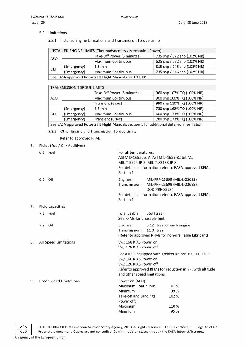
TCDS No.: EASA.R.005 A109/A119
Issue: 20 Date: 20 June 2018
TE.CERT.00049-001 © European Aviation Safety Agency, 2018. All rights reserved. ISO9001 certified. Page 43 of 62 Proprietary document. Copies are not controlled. Confirm revision status through the EASA-Internet/Intranet.
An agency of the European Union
5.3 Limitations
5.3.1 Installed Engine Limitations and Transmission Torque Limits
INSTALLED ENGINE LIMITS (Thermodynamics / Mechanical Power)
AEO Take-Off Power (5 minutes) 735 shp / 572 shp (102% NR)
Maximum Continuous 625 shp / 572 shp (102% NR)
OEI (Emergency) 2.5 min 815 shp / 745 shp (102% NR)
(Emergency) Maximum Continuous 735 shp / 646 shp (102% NR)
See EASA approved Rotorcraft Flight Manuals for TOT, N1
TRANSMISSION TORQUE LIMITS
AEO
Take-Off Power (5 minutes) 960 shp 107% TQ (100% NR)
Maximum Continuous 900 shp 100% TQ (100% NR)
Transient (6 sec) 990 shp 110% TQ (100% NR)
OEI
(Emergency) 2.5 min 730 shp 162% TQ (100% NR)
(Emergency) Maximum Continuous 600 shp 133% TQ (100% NR)
(Emergency) Transient (6 sec) 780 shp 173% TQ (100% NR)
See EASA approved Rotorcraft Flight Manuals Section 1 for additional detailed information
5.3.2 Other Engine and Transmission Torque Limits
Refer to approved RFMs
6. Fluids (Fuel/ Oil/ Additives)
6.1 Fuel For all temperatures: ASTM D-1655 Jet A, ASTM D-1655-82 Jet A1, MIL-T-5624 JP-5, MIL-T-83133 JP-8 For detailed information refer to EASA approved RFMs Section 1
6.2 Oil Engines: MIL-PRF-23699 (MIL-L-23699) Transmission: MIL-PRF-23699 (MIL-L-23699),
DOD-PRF-85734 For detailed information refer to EASA approved RFMs Section 1
7. Fluid capacities
7.1 Fuel Total usable: 563 litres See RFMs for unusable fuel.
7.2 Oil Engines: 5.12 litres for each engine Transmission: 11.0 litres (Refer to approved RFMs for non-drainable lubricant)
8. Air Speed Limitations VNE: 168 KIAS Power on VNE: 128 KIAS Power off
For A109S equipped with Trekker kit p/n 109G0000F01: VNE: 160 KIAS Power on VNE: 120 KIAS Power off Refer to approved RFMs for reduction in VNE with altitude and other speed limitations
9. Rotor Speed Limitations Power on (AEO): Maximum Continuous 101 % Minimum 99 % Take-off and Landings 102 % Power off: Maximum 110 % Minimum 95 %
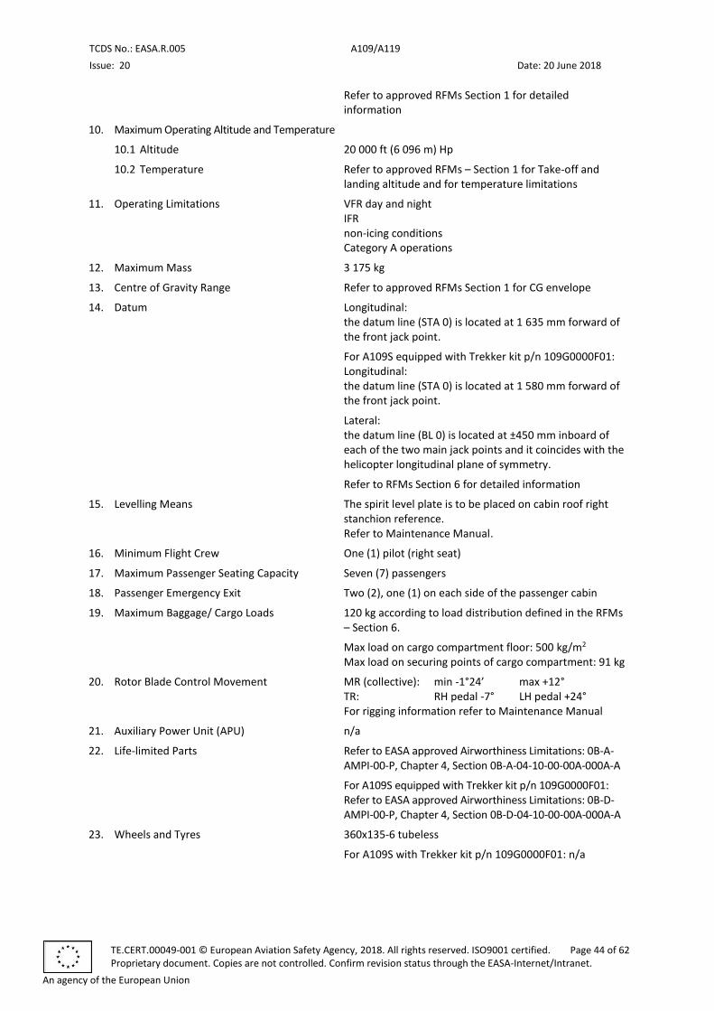
TCDS No.: EASA.R.005 A109/A119
Issue: 20 Date: 20 June 2018
TE.CERT.00049-001 © European Aviation Safety Agency, 2018. All rights reserved. ISO9001 certified. Page 44 of 62 Proprietary document. Copies are not controlled. Confirm revision status through the EASA-Internet/Intranet.
An agency of the European Union
Refer to approved RFMs Section 1 for detailed information
10. Maximum Operating Altitude and Temperature
10.1 Altitude 20 000 ft (6 096 m) Hp
10.2 Temperature Refer to approved RFMs – Section 1 for Take-off and landing altitude and for temperature limitations
11. Operating Limitations VFR day and night IFR non-icing conditions Category A operations
12. Maximum Mass 3 175 kg
13. Centre of Gravity Range Refer to approved RFMs Section 1 for CG envelope
14. Datum Longitudinal: the datum line (STA 0) is located at 1 635 mm forward of the front jack point.
For A109S equipped with Trekker kit p/n 109G0000F01: Longitudinal: the datum line (STA 0) is located at 1 580 mm forward of the front jack point.
Lateral: the datum line (BL 0) is located at ±450 mm inboard of each of the two main jack points and it coincides with the helicopter longitudinal plane of symmetry.
Refer to RFMs Section 6 for detailed information
15. Levelling Means The spirit level plate is to be placed on cabin roof right stanchion reference. Refer to Maintenance Manual.
16. Minimum Flight Crew One (1) pilot (right seat)
17. Maximum Passenger Seating Capacity Seven (7) passengers
18. Passenger Emergency Exit Two (2), one (1) on each side of the passenger cabin
19. Maximum Baggage/ Cargo Loads 120 kg according to load distribution defined in the RFMs – Section 6.
Max load on cargo compartment floor: 500 kg/m2 Max load on securing points of cargo compartment: 91 kg
20. Rotor Blade Control Movement MR (collective): min -1°24’ max +12° TR: RH pedal -7° LH pedal +24° For rigging information refer to Maintenance Manual
21. Auxiliary Power Unit (APU) n/a
22. Life-limited Parts Refer to EASA approved Airworthiness Limitations: 0B-A-AMPI-00-P, Chapter 4, Section 0B-A-04-10-00-00A-000A-A
For A109S equipped with Trekker kit p/n 109G0000F01: Refer to EASA approved Airworthiness Limitations: 0B-D-AMPI-00-P, Chapter 4, Section 0B-D-04-10-00-00A-000A-A
23. Wheels and Tyres 360x135-6 tubeless
For A109S with Trekker kit p/n 109G0000F01: n/a
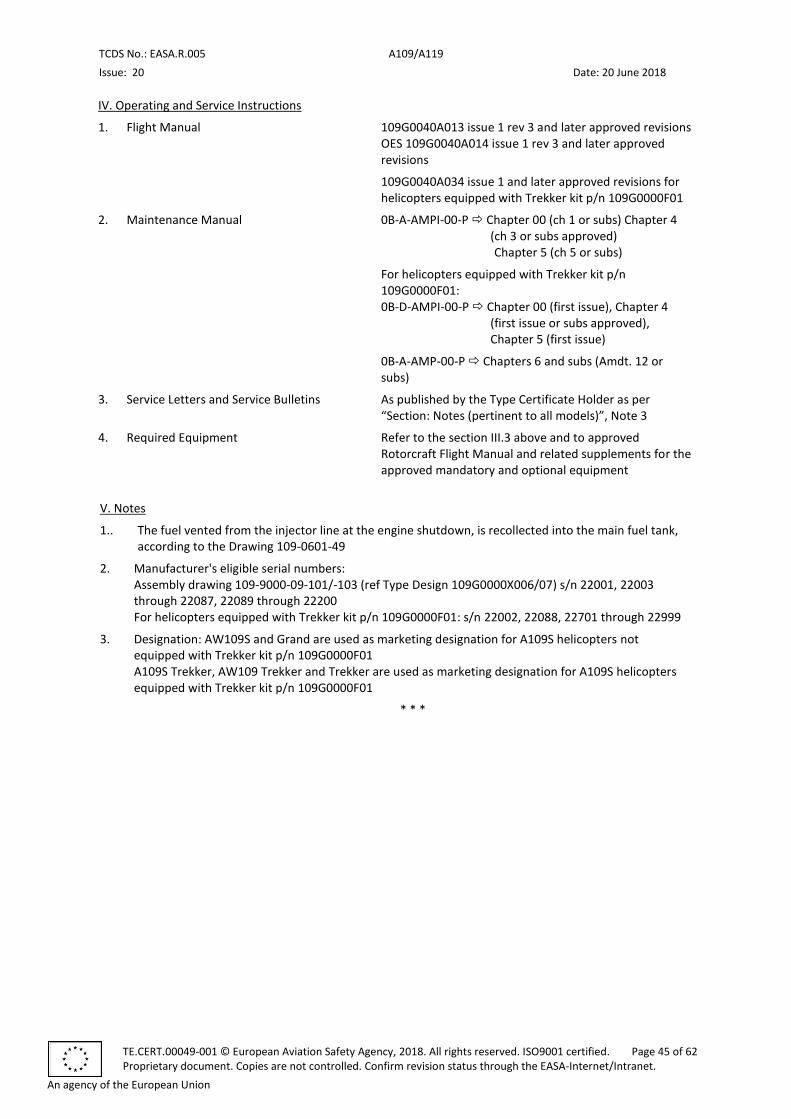
TCDS No.: EASA.R.005 A109/A119
Issue: 20 Date: 20 June 2018
TE.CERT.00049-001 © European Aviation Safety Agency, 2018. All rights reserved. ISO9001 certified. Page 45 of 62 Proprietary document. Copies are not controlled. Confirm revision status through the EASA-Internet/Intranet.
An agency of the European Union
IV. Operating and Service Instructions
1. Flight Manual 109G0040A013 issue 1 rev 3 and later approved revisions OES 109G0040A014 issue 1 rev 3 and later approved revisions
109G0040A034 issue 1 and later approved revisions for helicopters equipped with Trekker kit p/n 109G0000F01
2. Maintenance Manual 0B-A-AMPI-00-P Chapter 00 (ch 1 or subs) Chapter 4 (ch 3 or subs approved) Chapter 5 (ch 5 or subs)
For helicopters equipped with Trekker kit p/n 109G0000F01: 0B-D-AMPI-00-P Chapter 00 (first issue), Chapter 4
(first issue or subs approved), Chapter 5 (first issue)
0B-A-AMP-00-P Chapters 6 and subs (Amdt. 12 or subs)
3. Service Letters and Service Bulletins As published by the Type Certificate Holder as per “Section: Notes (pertinent to all models)”, Note 3
4. Required Equipment Refer to the section III.3 above and to approved Rotorcraft Flight Manual and related supplements for the approved mandatory and optional equipment
V. Notes
1.. The fuel vented from the injector line at the engine shutdown, is recollected into the main fuel tank, according to the Drawing 109-0601-49
2. Manufacturer's eligible serial numbers: Assembly drawing 109-9000-09-101/-103 (ref Type Design 109G0000X006/07) s/n 22001, 22003 through 22087, 22089 through 22200 For helicopters equipped with Trekker kit p/n 109G0000F01: s/n 22002, 22088, 22701 through 22999
3. Designation: AW109S and Grand are used as marketing designation for A109S helicopters not equipped with Trekker kit p/n 109G0000F01 A109S Trekker, AW109 Trekker and Trekker are used as marketing designation for A109S helicopters equipped with Trekker kit p/n 109G0000F01
* * *
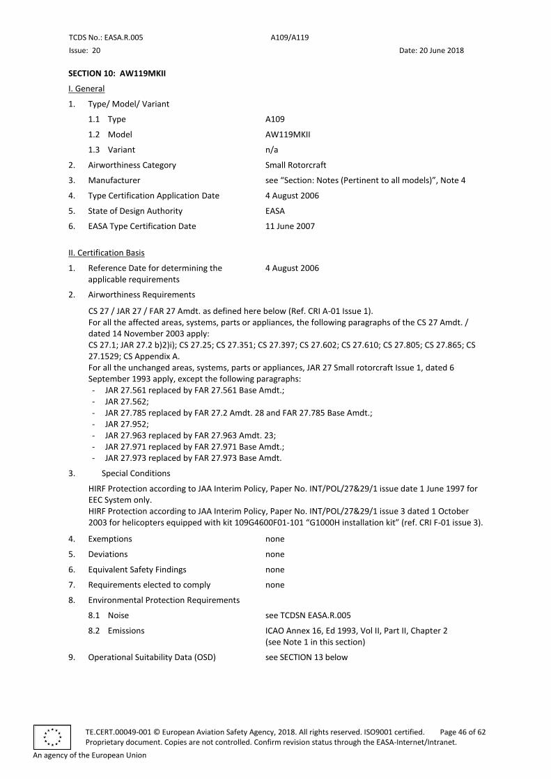
TCDS No.: EASA.R.005 A109/A119
Issue: 20 Date: 20 June 2018
TE.CERT.00049-001 © European Aviation Safety Agency, 2018. All rights reserved. ISO9001 certified. Page 46 of 62 Proprietary document. Copies are not controlled. Confirm revision status through the EASA-Internet/Intranet.
An agency of the European Union
SECTION 10: AW119MKII
I. General
1. Type/ Model/ Variant
1.1 Type A109
1.2 Model AW119MKII
1.3 Variant n/a
2. Airworthiness Category Small Rotorcraft
3. Manufacturer see “Section: Notes (Pertinent to all models)”, Note 4
4. Type Certification Application Date 4 August 2006
5. State of Design Authority EASA
6. EASA Type Certification Date 11 June 2007
II. Certification Basis
1. Reference Date for determining the applicable requirements
4 August 2006
2. Airworthiness Requirements
CS 27 / JAR 27 / FAR 27 Amdt. as defined here below (Ref. CRI A-01 Issue 1). For all the affected areas, systems, parts or appliances, the following paragraphs of the CS 27 Amdt. / dated 14 November 2003 apply: CS 27.1; JAR 27.2 b)2)i); CS 27.25; CS 27.351; CS 27.397; CS 27.602; CS 27.610; CS 27.805; CS 27.865; CS 27.1529; CS Appendix A. For all the unchanged areas, systems, parts or appliances, JAR 27 Small rotorcraft Issue 1, dated 6 September 1993 apply, except the following paragraphs: - JAR 27.561 replaced by FAR 27.561 Base Amdt.; - JAR 27.562; - JAR 27.785 replaced by FAR 27.2 Amdt. 28 and FAR 27.785 Base Amdt.; - JAR 27.952; - JAR 27.963 replaced by FAR 27.963 Amdt. 23; - JAR 27.971 replaced by FAR 27.971 Base Amdt.; - JAR 27.973 replaced by FAR 27.973 Base Amdt.
3. Special Conditions
HIRF Protection according to JAA Interim Policy, Paper No. INT/POL/27&29/1 issue date 1 June 1997 for EEC System only. HIRF Protection according to JAA Interim Policy, Paper No. INT/POL/27&29/1 issue 3 dated 1 October 2003 for helicopters equipped with kit 109G4600F01-101 “G1000H installation kit” (ref. CRI F-01 issue 3).
4. Exemptions none
5. Deviations none
6. Equivalent Safety Findings none
7. Requirements elected to comply none
8. Environmental Protection Requirements
8.1 Noise see TCDSN EASA.R.005
8.2 Emissions ICAO Annex 16, Ed 1993, Vol II, Part II, Chapter 2 (see Note 1 in this section)
9. Operational Suitability Data (OSD) see SECTION 13 below

TCDS No.: EASA.R.005 A109/A119
Issue: 20 Date: 20 June 2018
TE.CERT.00049-001 © European Aviation Safety Agency, 2018. All rights reserved. ISO9001 certified. Page 47 of 62 Proprietary document. Copies are not controlled. Confirm revision status through the EASA-Internet/Intranet.
An agency of the European Union
III. Technical Characteristics and Operational Limitations
1. Type Design Definition Refer to Type Design Definition 109G0000X016 Rev. A and subsequent
2. Description Single engine rotorcraft controlled by Electronic Engine Control (EEC), four (4) composite MR blades, articulated (with elastomeric bearings) main rotor, twin (2) composite blade teetering tail rotor, skid landing gear, one (1) pilot and seven (7) passengers capacity.
3. Equipment
Basic equipment required by the airworthiness rules (see Certification Basis) shall be installed on the helicopter for the Airworthiness Certificate release.
Besides, the following equipment are required:
- Data relevant to outside air temperature, provided by IDS and external probe P/N E22307-2-4
Approved mandatory and optional equipment are listed in the report 109G0840W030 “AW119MKII Chart A – Equipment List” and in the report 109G0840W046 for AW119MkII helicopters equipped with kit 109G4600F01-101 "G1000H Installation kit".
Refer also to the Equipment list in RFM
4. Dimensions
4.1 Fuselage Length: 11.14 m Width: 2.88 m Height: 3.60 m
4.2 Main Rotor Diameter: 10.83 m
4.3 Tail Rotor Diameter: 1.94 m
5. Engine
5.1 Model Pratt & Whitney Canada
1 x Model PT6B-37A Build Specification No. 1242
5.2 Type Certificate State of Design Engine TC/TCDS n°: TCCA E-20
EASA TC/TCDS n°: EASA.IM.E.039
5.3 Limitations
5.3.1 Installed Engine Limitations and Transmission Torque Limits
INSTALLED ENGINE LIMITS
Take-Off (5 minutes) 917 shp, 108.5% TQ (102% NR)
Maximum Continuous 847 shp, 100% TQ (100% NR)
See EASA approved Rotorcraft Flight Manuals for ITT and N1 limits
TRANSMISSION TORQUE LIMITS
Take-Off (5 minutes) 917 shp, 108.5% TQ (102% NR)
Maximum Continuous 900 shp, 106.5% TQ (102% NR)
See EASA approved Rotorcraft Flight Manuals Section 1
5.3.2 Other Engine and Transmission Torque Limits
Refer to approved RFM
6. Fluids (Fuel/ Oil/ Additives)
6.1 Fuel For all temperatures: ASTM D1655 Type Jet A, ASTM D1655 Type Jet A-1, MIL-T-5624 Type JP-5, MIL-T-83133 Type JP-8
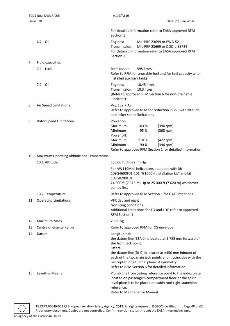
TCDS No.: EASA.R.005 A109/A119
Issue: 20 Date: 20 June 2018
TE.CERT.00049-001 © European Aviation Safety Agency, 2018. All rights reserved. ISO9001 certified. Page 48 of 62 Proprietary document. Copies are not controlled. Confirm revision status through the EASA-Internet/Intranet.
An agency of the European Union
For detailed information refer to EASA approved RFM Section 1
6.2 Oil Engines: MIL-PRF-23699 or PWA-521 Transmission: MIL-PRF-23699 or DOD-L-85734 For detailed information refer to EASA approved RFM Section 1
7. Fluid capacities
7.1 Fuel Total usable: 595 litres Refer to RFM for unusable fuel and for fuel capacity when installed auxiliary tanks.
7.2 Oil Engines: 10.45 litres Transmission: 10.3 litres (Refer to approved RFM Section 6 for non-drainable lubricant)
8. Air Speed Limitations VNE: 152 KIAS Refer to approved RFM for reduction in VNE with altitude and other speed limitations
9. Rotor Speed Limitations Power on: Maximum 103 % (396 rpm) Minimum 95 % (365 rpm) Power off: Maximum 110 % (422 rpm) Minimum 90 % (346 rpm) Refer to approved RFM Section 1 for detailed information
10. Maximum Operating Altitude and Temperature
10.1 Altitude 15 000 ft (4 572 m) Hp
For AW119MkII helicopters equipped with kit 109G4600F01-101 "G1000H Installation kit" and kit 109G0200F01: 24 000 ft (7 315 m) Hp or 25 000 ft (7 620 m) whichever comes first
10.2 Temperature Refer to approved RFM Section 1 for OAT limitations
11. Operating Limitations VFR day and night Non-icing conditions Additional limitations for TO and LDG refer to approved RFM Section 1
12. Maximum Mass 2 850 kg
13. Centre of Gravity Range Refer to approved RFM for CG envelope
14. Datum Longitudinal: the datum line (STA 0) is located at 1 785 mm forward of the front jack point. Lateral: the datum line (BL 0) is located at ±450 mm inboard of each of the two main jack points and it coincides with the helicopter longitudinal plane of symmetry. Refer to RFM Section 6 for detailed information
15. Levelling Means Plumb line from ceiling reference point to the index plate located on passengers compartment floor or the spirit level plate is to be placed on cabin roof right stanchion reference. Refer to Maintenance Manual.
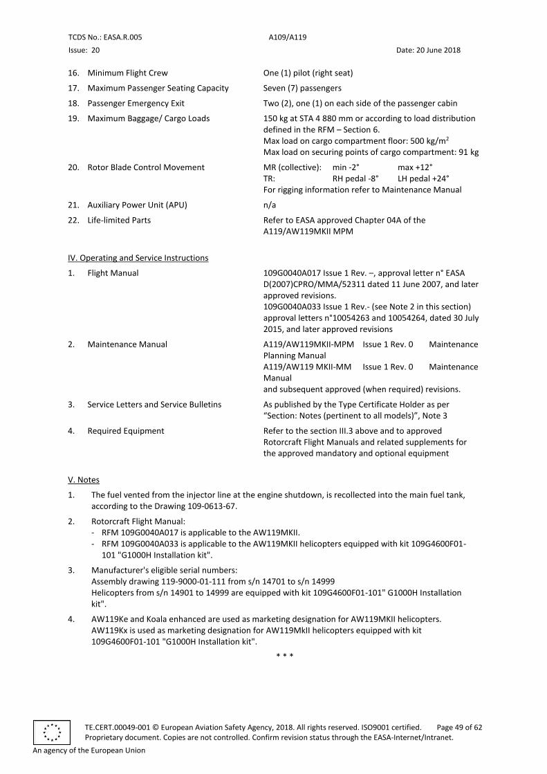
TCDS No.: EASA.R.005 A109/A119
Issue: 20 Date: 20 June 2018
TE.CERT.00049-001 © European Aviation Safety Agency, 2018. All rights reserved. ISO9001 certified. Page 49 of 62 Proprietary document. Copies are not controlled. Confirm revision status through the EASA-Internet/Intranet.
An agency of the European Union
16. Minimum Flight Crew One (1) pilot (right seat)
17. Maximum Passenger Seating Capacity Seven (7) passengers
18. Passenger Emergency Exit Two (2), one (1) on each side of the passenger cabin
19. Maximum Baggage/ Cargo Loads 150 kg at STA 4 880 mm or according to load distribution defined in the RFM – Section 6. Max load on cargo compartment floor: 500 kg/m2 Max load on securing points of cargo compartment: 91 kg
20. Rotor Blade Control Movement MR (collective): min -2° max +12° TR: RH pedal -8° LH pedal +24° For rigging information refer to Maintenance Manual
21. Auxiliary Power Unit (APU) n/a
22. Life-limited Parts Refer to EASA approved Chapter 04A of the A119/AW119MKII MPM
IV. Operating and Service Instructions
1. Flight Manual 109G0040A017 Issue 1 Rev. –, approval letter n° EASA D(2007)CPRO/MMA/52311 dated 11 June 2007, and later approved revisions. 109G0040A033 Issue 1 Rev.- (see Note 2 in this section) approval letters n°10054263 and 10054264, dated 30 July 2015, and later approved revisions
2. Maintenance Manual A119/AW119MKII-MPM Issue 1 Rev. 0 Maintenance Planning Manual A119/AW119 MKII-MM Issue 1 Rev. 0 Maintenance Manual and subsequent approved (when required) revisions.
3. Service Letters and Service Bulletins As published by the Type Certificate Holder as per “Section: Notes (pertinent to all models)”, Note 3
4. Required Equipment Refer to the section III.3 above and to approved Rotorcraft Flight Manuals and related supplements for the approved mandatory and optional equipment
V. Notes
1. The fuel vented from the injector line at the engine shutdown, is recollected into the main fuel tank, according to the Drawing 109-0613-67.
2. Rotorcraft Flight Manual: - RFM 109G0040A017 is applicable to the AW119MKII. - RFM 109G0040A033 is applicable to the AW119MKII helicopters equipped with kit 109G4600F01-
101 "G1000H Installation kit".
3. Manufacturer's eligible serial numbers: Assembly drawing 119-9000-01-111 from s/n 14701 to s/n 14999 Helicopters from s/n 14901 to 14999 are equipped with kit 109G4600F01-101" G1000H Installation kit".
4. AW119Ke and Koala enhanced are used as marketing designation for AW119MKII helicopters. AW119Kx is used as marketing designation for AW119MkII helicopters equipped with kit 109G4600F01-101 "G1000H Installation kit".
* * *
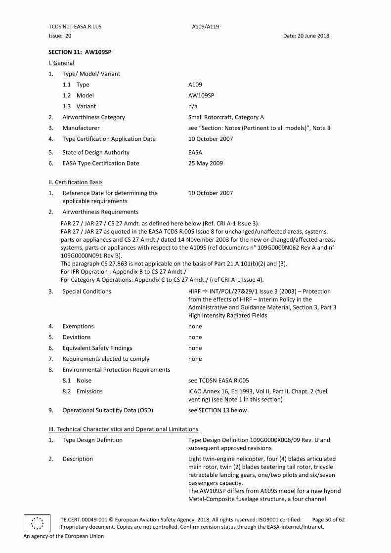
TCDS No.: EASA.R.005 A109/A119
Issue: 20 Date: 20 June 2018
TE.CERT.00049-001 © European Aviation Safety Agency, 2018. All rights reserved. ISO9001 certified. Page 50 of 62 Proprietary document. Copies are not controlled. Confirm revision status through the EASA-Internet/Intranet.
An agency of the European Union
SECTION 11: AW109SP
I. General
1. Type/ Model/ Variant
1.1 Type A109
1.2 Model AW109SP
1.3 Variant n/a
2. Airworthiness Category Small Rotorcraft, Category A
3. Manufacturer see “Section: Notes (Pertinent to all models)”, Note 3
4. Type Certification Application Date 10 October 2007
5. State of Design Authority EASA
6. EASA Type Certification Date 25 May 2009
II. Certification Basis
1. Reference Date for determining the applicable requirements
10 October 2007
2. Airworthiness Requirements
FAR 27 / JAR 27 / CS 27 Amdt. as defined here below (Ref. CRI A-1 Issue 3). FAR 27 / JAR 27 as quoted in the EASA TCDS R.005 Issue 8 for unchanged/unaffected areas, systems, parts or appliances and CS 27 Amdt./ dated 14 November 2003 for the new or changed/affected areas, systems, parts or appliances with respect to the A109S (ref documents n° 109G0000N062 Rev A and n° 109G0000N091 Rev B). The paragraph CS 27.863 is not applicable on the basis of Part 21.A.101(b)(2) and (3). For IFR Operation : Appendix B to CS 27 Amdt./ For Category A Operations: Appendix C to CS 27 Amdt./ (ref CRI A-1 Issue 4).
3. Special Conditions HIRF INT/POL/27&29/1 Issue 3 (2003) – Protection from the effects of HIRF – Interim Policy in the Administrative and Guidance Material, Section 3, Part 3 High Intensity Radiated Fields.
4. Exemptions none
5. Deviations none
6. Equivalent Safety Findings none
7. Requirements elected to comply none
8. Environmental Protection Requirements
8.1 Noise see TCDSN EASA.R.005
8.2 Emissions ICAO Annex 16, Ed 1993, Vol II, Part II, Chapt. 2 (fuel venting) (see Note 1 in this section)
9. Operational Suitability Data (OSD) see SECTION 13 below
III. Technical Characteristics and Operational Limitations
1. Type Design Definition Type Design Definition 109G0000X006/09 Rev. U and subsequent approved revisions
2. Description Light twin-engine helicopter, four (4) blades articulated main rotor, twin (2) blades teetering tail rotor, tricycle retractable landing gears, one/two pilots and six/seven passengers capacity. The AW109SP differs from A109S model for a new hybrid Metal-Composite fuselage structure, a four channel
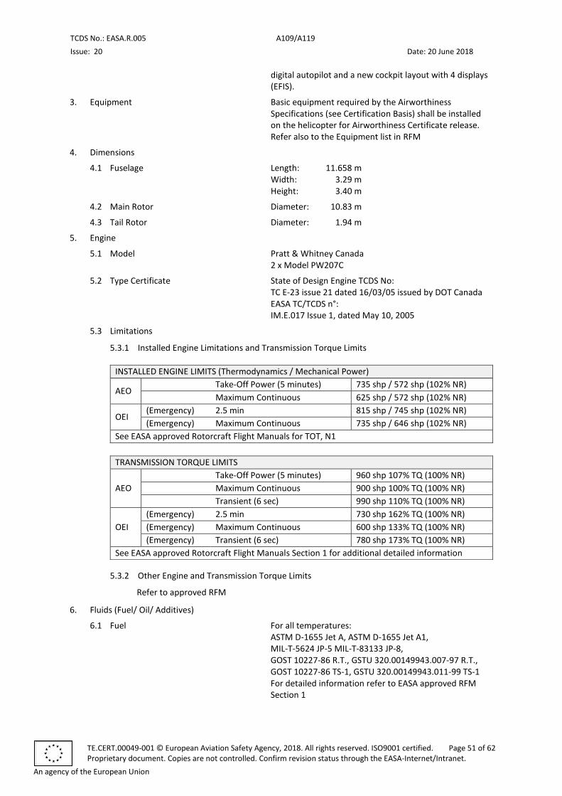
TCDS No.: EASA.R.005 A109/A119
Issue: 20 Date: 20 June 2018
TE.CERT.00049-001 © European Aviation Safety Agency, 2018. All rights reserved. ISO9001 certified. Page 51 of 62 Proprietary document. Copies are not controlled. Confirm revision status through the EASA-Internet/Intranet.
An agency of the European Union
digital autopilot and a new cockpit layout with 4 displays (EFIS).
3. Equipment Basic equipment required by the Airworthiness Specifications (see Certification Basis) shall be installed on the helicopter for Airworthiness Certificate release. Refer also to the Equipment list in RFM
4. Dimensions
4.1 Fuselage Length: 11.658 m Width: 3.29 m Height: 3.40 m
4.2 Main Rotor Diameter: 10.83 m
4.3 Tail Rotor Diameter: 1.94 m
5. Engine
5.1 Model Pratt & Whitney Canada 2 x Model PW207C
5.2 Type Certificate State of Design Engine TCDS No: TC E-23 issue 21 dated 16/03/05 issued by DOT Canada EASA TC/TCDS n°: IM.E.017 Issue 1, dated May 10, 2005
5.3 Limitations
5.3.1 Installed Engine Limitations and Transmission Torque Limits
INSTALLED ENGINE LIMITS (Thermodynamics / Mechanical Power)
AEO Take-Off Power (5 minutes) 735 shp / 572 shp (102% NR)
Maximum Continuous 625 shp / 572 shp (102% NR)
OEI (Emergency) 2.5 min 815 shp / 745 shp (102% NR)
(Emergency) Maximum Continuous 735 shp / 646 shp (102% NR)
See EASA approved Rotorcraft Flight Manuals for TOT, N1
TRANSMISSION TORQUE LIMITS
AEO
Take-Off Power (5 minutes) 960 shp 107% TQ (100% NR)
Maximum Continuous 900 shp 100% TQ (100% NR)
Transient (6 sec) 990 shp 110% TQ (100% NR)
OEI
(Emergency) 2.5 min 730 shp 162% TQ (100% NR)
(Emergency) Maximum Continuous 600 shp 133% TQ (100% NR)
(Emergency) Transient (6 sec) 780 shp 173% TQ (100% NR)
See EASA approved Rotorcraft Flight Manuals Section 1 for additional detailed information
5.3.2 Other Engine and Transmission Torque Limits
Refer to approved RFM
6. Fluids (Fuel/ Oil/ Additives)
6.1 Fuel For all temperatures: ASTM D-1655 Jet A, ASTM D-1655 Jet A1, MIL-T-5624 JP-5 MIL-T-83133 JP-8, GOST 10227-86 R.T., GSTU 320.00149943.007-97 R.T., GOST 10227-86 TS-1, GSTU 320.00149943.011-99 TS-1 For detailed information refer to EASA approved RFM Section 1
TCDS No.: EASA.R.005 A109/A119
Issue: 20 Date: 20 June 2018
TE.CERT.00049-001 © European Aviation Safety Agency, 2018. All rights reserved. ISO9001 certified. Page 52 of 62 Proprietary document. Copies are not controlled. Confirm revision status through the EASA-Internet/Intranet.
An agency of the European Union
6.2 Oil Engines: MIL-PRF-23699 Transmission: MIL-PRF-23699
DOD-PRF-85734 For detailed information refer to EASA approved RFM Section 1
7. Fluid capacities
7.1 Fuel Usable fuel: 563 litres See RFM for unusable fuel.
7.2 Oil Engines: 5.12 litres for each engine Transmission: 11.0 litres (Refer to approved RFM for non-drainable lubricant)
8. Air Speed Limitations VNE: 168 KIAS Power on VNE: 128 KIAS Power off Refer to approved RFM for reduction in VNE with altitude and other speed limitations
9. Rotor Speed Limitations Power on (AEO): Maximum Continuous 101 % Minimum 99 % Take-off and Landings 102 % Power off: Maximum 110 % Minimum 95 % Refer to approved RFM Section 1 for detailed information
10. Maximum Operating Altitude and Temperature
10.1 Altitude 20 000 ft (6 096 m) Hp
10.2 Temperature Refer to approved RFM Section 1 for Take-off and landing altitude and for temperature limitations
11. Operating Limitations VFR day and night IFR non-icing conditions Category A operations
12. Maximum Mass 3 175 kg
13. Centre of Gravity Range Refer to approved RFM Section 1 for CG envelope
14. Datum Longitudinal: the datum line (STA 0) is located at 1 635 mm forward of the front jack point. Lateral: the datum line (BL 0) is located at ±450 mm inboard of each of the two main jack points and it coincides with the helicopter longitudinal plane of symmetry. Refer to RFM Section 6 for detailed information
15. Levelling Means The spirit level plate is to be placed on cabin roof right stanchion reference Refer to Maintenance Manual.
16. Minimum Flight Crew One (1) pilot (right seat)
17. Maximum Passenger Seating Capacity Seven (7) passengers
18. Passenger Emergency Exit Two (2), one (1) on each side of the passenger cabin
19. Maximum Baggage/ Cargo Loads 120 kg according to load distribution defined in the RFM – Section 6. Max load on cargo compartment floor: 500 kg/m2
TCDS No.: EASA.R.005 A109/A119
Issue: 20 Date: 20 June 2018
TE.CERT.00049-001 © European Aviation Safety Agency, 2018. All rights reserved. ISO9001 certified. Page 53 of 62 Proprietary document. Copies are not controlled. Confirm revision status through the EASA-Internet/Intranet.
An agency of the European Union
Max load on securing points of cargo compartment: 91 kg
20. Rotor Blade Control Movement MR (collective): min -1°24’ max +12° TR: RH pedal -7° LH pedal +24° For rigging information refer to Maintenance Manual
21. Auxiliary Power Unit (APU) n/a
22. Life-limited Parts For helicopter s/n 22201, 22203, 22214 and subs: Refer to EASA approved Airworthiness Limitations 0B-B-AMPI-00-P, Chapter 4, Section 0B-B-04-10-00-00A-000B-A For helicopter s/n 22202, 22204 thru 22213: Refer to EASA approved Airworthiness Limitations 0B-C-AMPI-00-P, Chapter 4, Section 0B-C-04-10-00-00A-000B-A
23. Wheels and Tyres 360x135-6 tubeless
IV. Operating and Service Instructions
1. Flight Manual 109G0040A018 AW109SP Issue B and later approved revisions 109G0040A019 AW109SP Optional Equipment Supplement Issue B and later approved revisions (for NVIS operation as per Note 2 in this section, refer to supplement 10) For helicopter with Rega Customisation (P/N 109-B810-12-101): 109G0040A020 AW109SP REGA RFM Issue B and later approved revisions 109G0040A021 AW109SP REGA Optional Equipment Supplement Issue B and later approved revisions (for NVIS operation as per Note 4 in this section, refer to supplement 9.1-2)
2. Maintenance Manual For helicopter s/n 22201, 22203 and subsequent: AMPI 0B-B-AMPI-00-P Chapter 00 (first issue change 2 and subs. approved revisions). Chapter 04 (second issue change 2 and subs. EASA approved revisions) with: - Retirement lives (0B-B-04-10-00-00A-000B-A) - Mandatory inspections (0B-B-04-20-00-00A-000B-A) - CMR (0B-B-04-30-00-00A-000B-A) Chapter 5 (first issue – change 11 and subsequent approved revisions). For helicopter s/n 22202, 22204 thru 22213: AMPI 0B-C-AMPI-00-P Chapter 00 (second issue change / and subs. approved revisions) Chapter 04 (first issue change 3 and subs. EASA approved revisions) with: - Retirement lives (0B-C-04-10-00-00A-000B-A) - Mandatory inspections (0B-C-04-20-00-00A-000B-A) - CMR (0B-C-04-30-00-00A-000B-A) Chapter 5 (second issue – change 2 and subs. approved revisions) For all helicopter: AMP 0B-A-AMP-00-X Chapters 06 and subs (first issue and subs. approved revisions)
TCDS No.: EASA.R.005 A109/A119
Issue: 20 Date: 20 June 2018
TE.CERT.00049-001 © European Aviation Safety Agency, 2018. All rights reserved. ISO9001 certified. Page 54 of 62 Proprietary document. Copies are not controlled. Confirm revision status through the EASA-Internet/Intranet.
An agency of the European Union
6. Service Letters and Service Bulletins As published by the Type Certificate Holder as per “Section: Notes (pertinent to all models)”, Note 3
7. Required Equipment Refer to the section III.3 above and to approved RFM and related supplements for the approved mandatory and optional equipment
V. Notes
1. The fuel vented from the injector line at the engine shutdown, is recollected into the main fuel tank, according to the Drawing 109-0601-49
2. Kit P/N 109-B810-12-101, per RFM 109G0040A021 Supplement n. 9.1-2., and Kit P/N 109-B810-12-103, per RFM 109G0040A019 Supplement n. 10, allow NVIS Operations. Modifications that add or change systems that emit or reflect light, have the potential to alter or change the NVIS lighting-NVG compatibility. For this reason, they require an engineering evaluation that must be approved by the aircraft certification authority. Subsequent modifications and Deviations to the NVG helicopter configuration shall be managed in accordance with document 109G3360E003 revision B “AW109SP HELICOPTER NVG POLICY”. The aircraft configuration involving internal/external emitting/reflecting equipment approved for use with NVG is described in the Report 109G3360A001 revision E “AW109SP NVG Compatibility Reference Handbook”
3. Manufacturer's eligible serial numbers: Assembly Drawing 109-9000-09-105/-107 (ref. Type Design 109G0000X006/09) from s/n 22201 to s/n 22499
4. Designation: GrandNew is used as marketing designation for AW109SP helicopters
5. The auxiliary installation Weather Radar RDR 2000 p/n 109-B810-15 is applicable to AW109SP helicopters S/N 22201, 22203, 22214, and subsequent.
* * *
TCDS No.: EASA.R.005 A109/A119
Issue: 20 Date: 20 June 2018
TE.CERT.00049-001 © European Aviation Safety Agency, 2018. All rights reserved. ISO9001 certified. Page 55 of 62 Proprietary document. Copies are not controlled. Confirm revision status through the EASA-Internet/Intranet.
An agency of the European Union
SECTION 12: A109N
I. General
1. Type/ Model/ Variant
1.1 Type A109
1.2 Model A109N
1.3 Variant n/a
2. Airworthiness Category Small Rotorcraft, Category A
3. Manufacturer see “Section: Notes (Pertinent to all models)”, Note 3
4. Type Certification Application Date 29 November 2005
5. State of Design Authority EASA
6. EASA Type Certification Date 29 November 2010
II. Certification Basis
1. Reference Date for determining the applicable requirements
29 November 2007
2. Airworthiness Requirements
FAR 27 / JAR 27 / CS 27 Amdt. as defined here below (ref CRI A-1 Issue 5). FAR 27 / JAR 27 as quoted in the EASA TCDS R.005 for unchanged/unaffected areas, systems, parts or appliances. CS 27 Amdt./ 14 November 2003 for the new or changed/affected areas, systems, parts or appliances with respect to the A109E (ref documents n°109G0000N023 Rev C and n°109G0000N025 Rev C), except the following paragraphs: CS 27.561 replaced by FAR 27.561 Base Amdt. (except for pilot and co-pilot seats) CS 27.785 replaced by FAR 27.785 Amdt. 21 (except for pilot and co-pilot seats) CS 27.963 replaced by FAR 27.963 Amdt. 23 CS 27.971 replaced by FAR 27.971 Base Amdt. CS 27.973 replaced by FAR 27.973 Base Amdt. For IFR Operation: Appendix B to CS 27 Amdt./ For Category A Operations: Appendix C to CS 27 Amdt./
3. Special Conditions HIRF INT/POL/27&29/1 Issue 3 (2003) – Protection from the effects of HIRF – Interim Policy in the Administrative and Guidance Material, Section 3, Part 3 High Intensity Radiated Fields.
4. Exemptions none
5. Deviations none
6. Equivalent Safety Findings none
7. Requirements elected to comply none
8. Environmental Protection Requirements
8.1 Noise see TCDSN EASA.R.005
8.2 Emissions ICAO Annex 16, Ed 1993, Vol II, Part II, Chapt. 2 (fuel venting) (see Note 1 to this SECTION 12)
9. Operational Suitability Data (OSD) Not required for rotorcraft that are no longer in production. CR (EU) 748/2012, as amended by CR (EU) 69/2014 does not require OSD elements for this model (see Article 7a, 1.).

TCDS No.: EASA.R.005 A109/A119
Issue: 20 Date: 20 June 2018
TE.CERT.00049-001 © European Aviation Safety Agency, 2018. All rights reserved. ISO9001 certified. Page 56 of 62 Proprietary document. Copies are not controlled. Confirm revision status through the EASA-Internet/Intranet.
An agency of the European Union
III. Technical Characteristics and Operational Limitations
1. Type Design Definition Type Design Definition document 109G0000X006/08 Rev. Z and subsequent approved revisions
2. Description Light twin-engine helicopter, four (4) blades articulated main rotor, twin (2) blades teetering tail rotor, tricycle retractable landing gears, one / two pilots and six / seven passengers capacity. The A109N differs from A109E model for the installation of Pratt & Whitney Canada PW207C turbo engines, controlled through FADEC, pilots crash resistant seats, main rotor group, engine and transmission oil cooling system, digital four-axis dual-duplex Automatic Flight Control System and full digital flight instruments and radio management system
3. Equipment Basic equipment required by the Airworthiness Specifications (see Certification Basis) shall be installed on the helicopter for Airworthiness Certificate release. In addition the following equipment is required: - Civil Configuration Kit P/N 109-B810-01-101 - Engine Fire Extinguisher P/N 109-0811-39-101 for
Category A Operations Approved mandatory and optional equipment are listed in the Report 109G0840W025/01, issue M “A109N Helicopter – Chart A Equipment list”.
4. Dimensions
4.1 Fuselage Length: 11.43 m Width: 3.29 m Height: 3.42 m
4.2 Main Rotor Diameter: 10.83 m
4.3 Tail Rotor Diameter: 1.94 m
5. Engine
5.1 Model Pratt & Whitney Canada 2 x Model PW207C
5.2 Type Certificate State of Design Engine TC/TCDS n°: TCCA E-23 EASA TC/TCDS n°: EASA.IM.E.017
5.3 Limitations
5.3.1 Installed Engine Limitations and Transmission Torque Limits
INSTALLED ENGINE LIMITS (Thermodynamics / Mechanical Power)
AEO Take-Off Power (5 minutes) 735 shp / 572 shp (102% NR)
Maximum Continuous 625 shp / 572 shp (102% NR)
OEI (Emergency) 2.5 min 815 shp / 745 shp (102% NR)
(Emergency) Maximum Continuous 735 shp / 646 shp (102% NR)
See EASA approved Rotorcraft Flight Manual for TOT, N1
TRANSMISSION TORQUE LIMITS
AEO
Take-Off Power (5 minutes) 960 shp 107% TQ (100% NR)
Maximum Continuous 900 shp 100% TQ (100% NR)
Transient (6 sec) 990 shp 110% TQ (100% NR)
OEI
(Emergency) 2.5 min 730 shp 162% TQ (100% NR)
(Emergency) Maximum Continuous 600 shp 133% TQ (100% NR)
(Emergency) Transient (6 sec) 780 shp 173% TQ (100% NR)
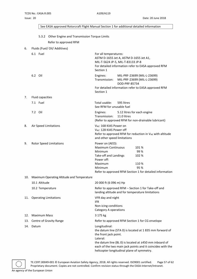
TCDS No.: EASA.R.005 A109/A119
Issue: 20 Date: 20 June 2018
TE.CERT.00049-001 © European Aviation Safety Agency, 2018. All rights reserved. ISO9001 certified. Page 57 of 62 Proprietary document. Copies are not controlled. Confirm revision status through the EASA-Internet/Intranet.
An agency of the European Union
See EASA approved Rotorcraft Flight Manual Section 1 for additional detailed information
5.3.2 Other Engine and Transmission Torque Limits
Refer to approved RFM
6. Fluids (Fuel/ Oil/ Additives)
6.1 Fuel For all temperatures: ASTM D-1655 Jet A, ASTM D-1655 Jet A1, MIL-T-5624 JP-5, MIL-T-83133 JP-8 For detailed information refer to EASA approved RFM Section 1
6.2 Oil Engines: MIL-PRF-23699 (MIL-L-23699) Transmission: MIL-PRF-23699 (MIL-L-23699)
DOD-PRF-85734 For detailed information refer to EASA approved RFM Section 1
7. Fluid capacities
7.1 Fuel Total usable: 595 litres See RFM for unusable fuel
7.2 Oil Engines: 5.12 litres for each engine Transmission: 11.0 litres (Refer to approved RFM for non-drainable lubricant)
8. Air Speed Limitations VNE: 168 KIAS Power on VNE: 128 KIAS Power off Refer to approved RFM for reduction in VNE with altitude and other speed limitations
9. Rotor Speed Limitations Power on (AEO): Maximum Continuous 101 % Minimum 99 % Take-off and Landings 102 % Power off: Maximum 110 % Minimum 95 % Refer to approved RFM Section 1 for detailed information
10. Maximum Operating Altitude and Temperature
10.1 Altitude 20 000 ft (6 096 m) Hp
10.2 Temperature Refer to approved RFM – Section 1 for Take-off and landing altitude and for temperature limitations
11. Operating Limitations VFR day and night IFR Non-icing conditions Category A operations
12. Maximum Mass 3 175 kg
13. Centre of Gravity Range Refer to approved RFM Section 1 for CG envelope
14. Datum Longitudinal: the datum line (STA 0) is located at 1 835 mm forward of the front jack point. Lateral: the datum line (BL 0) is located at ±450 mm inboard of each of the two main jack points and it coincides with the helicopter longitudinal plane of symmetry.
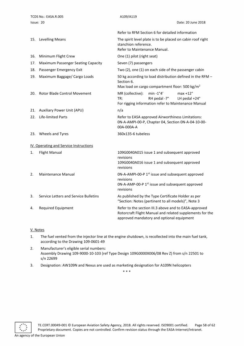
TCDS No.: EASA.R.005 A109/A119
Issue: 20 Date: 20 June 2018
TE.CERT.00049-001 © European Aviation Safety Agency, 2018. All rights reserved. ISO9001 certified. Page 58 of 62 Proprietary document. Copies are not controlled. Confirm revision status through the EASA-Internet/Intranet.
An agency of the European Union
Refer to RFM Section 6 for detailed information
15. Levelling Means The spirit level plate is to be placed on cabin roof right stanchion reference. Refer to Maintenance Manual.
16. Minimum Flight Crew One (1) pilot (right seat)
17. Maximum Passenger Seating Capacity Seven (7) passengers
18. Passenger Emergency Exit Two (2), one (1) on each side of the passenger cabin
19. Maximum Baggage/ Cargo Loads 50 kg according to load distribution defined in the RFM – Section 6. Max load on cargo compartment floor: 500 kg/m2
20. Rotor Blade Control Movement MR (collective): min -1°4’ max +12° TR: RH pedal -7° LH pedal +24° For rigging information refer to Maintenance Manual
21. Auxiliary Power Unit (APU) n/a
22. Life-limited Parts Refer to EASA approved Airworthiness Limitations: 0N-A-AMPI-00-P, Chapter 04, Section 0N-A-04-10-00-00A-000A-A
23. Wheels and Tyres 360x135-6 tubeless
IV. Operating and Service Instructions
1. Flight Manual 109G0040A015 issue 1 and subsequent approved revisions 109G0040A016 issue 1 and subsequent approved revisions
2. Maintenance Manual 0N-A-AMPI-00-P 1st issue and subsequent approved revisions 0N-A-AMP-00-P 1st issue and subsequent approved revisions
3. Service Letters and Service Bulletins As published by the Type Certificate Holder as per “Section: Notes (pertinent to all models)”, Note 3
4. Required Equipment Refer to the section III.3 above and to EASA-approved Rotorcraft Flight Manual and related supplements for the approved mandatory and optional equipment
V. Notes
1. The fuel vented from the injector line at the engine shutdown, is recollected into the main fuel tank, according to the Drawing 109-0601-49
2. Manufacturer's eligible serial numbers: Assembly Drawing 109-9000-10-103 (ref Type Design 109G0000X006/08 Rev Z) from s/n 22501 to s/n 22699
3. Designation: AW109N and Nexus are used as marketing designation for A109N helicopters
* * *
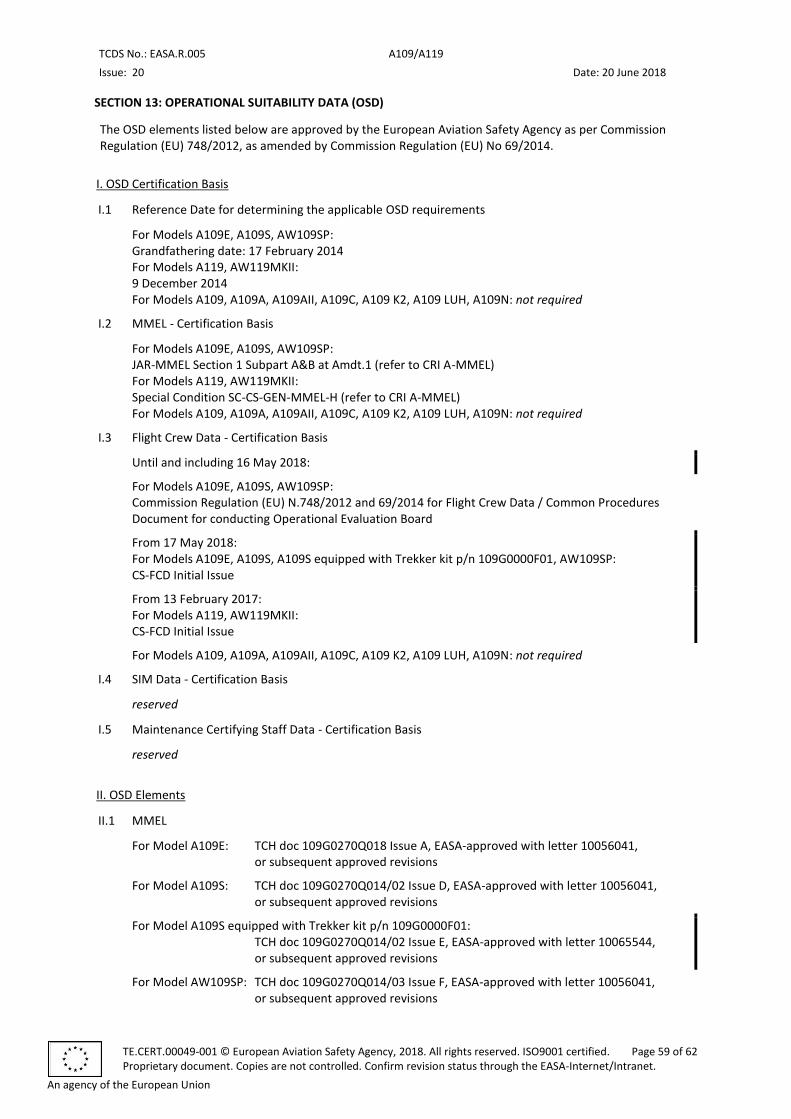
TCDS No.: EASA.R.005 A109/A119
Issue: 20 Date: 20 June 2018
TE.CERT.00049-001 © European Aviation Safety Agency, 2018. All rights reserved. ISO9001 certified. Page 59 of 62 Proprietary document. Copies are not controlled. Confirm revision status through the EASA-Internet/Intranet.
An agency of the European Union
SECTION 13: OPERATIONAL SUITABILITY DATA (OSD)
The OSD elements listed below are approved by the European Aviation Safety Agency as per Commission Regulation (EU) 748/2012, as amended by Commission Regulation (EU) No 69/2014.
I. OSD Certification Basis
I.1 Reference Date for determining the applicable OSD requirements
For Models A109E, A109S, AW109SP: Grandfathering date: 17 February 2014 For Models A119, AW119MKII: 9 December 2014 For Models A109, A109A, A109AII, A109C, A109 K2, A109 LUH, A109N: not required
I.2 MMEL - Certification Basis
For Models A109E, A109S, AW109SP: JAR-MMEL Section 1 Subpart A&B at Amdt.1 (refer to CRI A-MMEL) For Models A119, AW119MKII: Special Condition SC-CS-GEN-MMEL-H (refer to CRI A-MMEL) For Models A109, A109A, A109AII, A109C, A109 K2, A109 LUH, A109N: not required
I.3 Flight Crew Data - Certification Basis
Until and including 16 May 2018:
For Models A109E, A109S, AW109SP: Commission Regulation (EU) N.748/2012 and 69/2014 for Flight Crew Data / Common Procedures Document for conducting Operational Evaluation Board
From 17 May 2018: For Models A109E, A109S, A109S equipped with Trekker kit p/n 109G0000F01, AW109SP: CS-FCD Initial Issue
From 13 February 2017: For Models A119, AW119MKII: CS-FCD Initial Issue
For Models A109, A109A, A109AII, A109C, A109 K2, A109 LUH, A109N: not required
I.4 SIM Data - Certification Basis
reserved
I.5 Maintenance Certifying Staff Data - Certification Basis
reserved
II. OSD Elements
II.1 MMEL
For Model A109E: TCH doc 109G0270Q018 Issue A, EASA-approved with letter 10056041, or subsequent approved revisions
For Model A109S: TCH doc 109G0270Q014/02 Issue D, EASA-approved with letter 10056041, or subsequent approved revisions
For Model A109S equipped with Trekker kit p/n 109G0000F01: TCH doc 109G0270Q014/02 Issue E, EASA-approved with letter 10065544, or subsequent approved revisions
For Model AW109SP: TCH doc 109G0270Q014/03 Issue F, EASA-approved with letter 10056041, or subsequent approved revisions
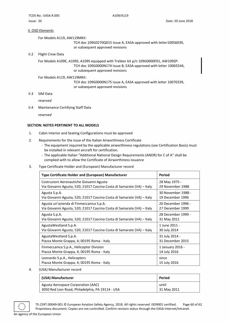
TCDS No.: EASA.R.005 A109/A119
Issue: 20 Date: 20 June 2018
TE.CERT.00049-001 © European Aviation Safety Agency, 2018. All rights reserved. ISO9001 certified. Page 60 of 62 Proprietary document. Copies are not controlled. Confirm revision status through the EASA-Internet/Intranet.
An agency of the European Union
II. OSD Elements
For Models A119, AW119MKII: TCH doc 109G0270Q015 Issue A, EASA-approved with letter10056039, or subsequent approved revisions
II.2 Flight Crew Data
For Models A109E, A109S, A109S equipped with Trekker kit p/n 109G0000F01, AW109SP: TCH doc 109G0000N174 Issue B, EASA-approved with letter 10065544, or subsequent approved revisions
For Models A119, AW119MKII: TCH doc 109G0000N175 issue A, EASA approved with letter 10070339, or subsequent approved revisions
II.3 SIM Data
reserved
II.4 Maintenance Certifying Staff Data
reserved
SECTION: NOTES PERTINENT TO ALL MODELS
1. Cabin Interior and Seating Configurations must be approved
2. Requirements for the issue of the Italian Airworthiness Certificate
- The equipment required by the applicable airworthiness regulations (see Certification Basis) must be installed in relevant aircraft for certification.
- The applicable Italian “Additional National Design Requirements (ANDR) for C of A” shall be complied with to allow the Certificate of Airworthiness issuance
3. Type Certificate Holder and (European) Manufacturer record
Type Certificate Holder and (European) Manufacturer Period
Costruzioni Aeronautiche Giovanni Agusta Via Giovanni Agusta, 520; 21017 Cascina Costa di Samarate (VA) – Italy
28 May 1975 - 29 November 1988
Agusta S.p.A. Via Giovanni Agusta, 520; 21017 Cascina Costa di Samarate (VA) – Italy
30 November 1988 - 19 December 1996
Agusta un’azienda di Finmeccanica S.p.A. Via Giovanni Agusta, 520; 21017 Cascina Costa di Samarate (VA) – Italy
20 December 1996 - 27 December 1999
Agusta S.p.A. Via Giovanni Agusta, 520; 21017 Cascina Costa di Samarate (VA) – Italy
28 December 1999 - 31 May 2011
AgustaWestland S.p.A. Via Giovanni Agusta, 520; 21017 Cascina Costa di Samarate (VA) – Italy
1 June 2011 - 30 July 2014
AgustaWestland S.p.A. Piazza Monte Grappa, 4; 00195 Roma - Italy
31 July 2014 - 31 December 2015
Finmeccanica S.p.A., Helicopter Division Piazza Monte Grappa, 4; 00195 Roma - Italy
1 January 2016 - 14 July 2016
Leonardo S.p.A., Helicopters Piazza Monte Grappa, 4; 00195 Roma - Italy
since 15 July 2016
4. (USA) Manufacturer record
(USA) Manufacturer Period
Agusta Aerospace Corporation (AAC) 3050 Red Lion Road, Philadelphia, PA 19114 - USA
until 31 May 2011
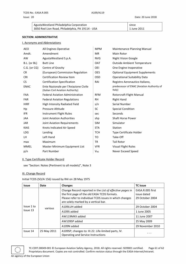
TCDS No.: EASA.R.005 A109/A119
Issue: 20 Date: 20 June 2018
TE.CERT.00049-001 © European Aviation Safety Agency, 2018. All rights reserved. ISO9001 certified. Page 61 of 62 Proprietary document. Copies are not controlled. Confirm revision status through the EASA-Internet/Intranet.
An agency of the European Union
AgustaWestland Philadelphia Corporation 3050 Red Lion Road, Philadelphia, PA 19114 - USA
since 1 June 2011
SECTION: ADMINISTRATIVE
I. Acronyms and Abbreviations
AEO All Engines Operative MPM Maintenance Planning Manual
Amdt. Amendment MR Main Rotor
AW AgustaWestland S.p.A. NVG Night Vision Google
B.L. (or BL) Butt Line OAT Outside Ambient Temperature
C.G. (or CG) Centre of Gravity OEI One Engine Inoperative
CR (European) Commission Regulation OES Optional Equipment Supplements
CRI Certification Review Item OSD Operational Suitability Data
CS Certification Specification RAI Registro Aeronautico Italiano,
ENAC Ente Nazionale per l'Aviazione Civile (Italian Civil Aviation Authority)
predecessor of ENAC (Aviation Authority of Italy)
FAA Federal Aviation Administration RFM Rotorcraft Flight Manual
FAR Federal Aviation Regulations RH Right Hand
HIRF High Intensity Radiated Field s/n Serial Number
Hp Pressure Altitude SC Special Condition
IFR Instrument Flight Rules sec Seconds
JAA Joint Aviation Authorities shp Shaft Horse Power
JAR Joint Aviation Requirements SIM Simulator
KIAS Knots Indicated Air Speed STA Station
LDG Landing TCH Type Certificate Holder
LH Left Hand TO Take-Off
max Maximum TR Tail Rotor
MMEL Master Minimum Equipment List VFR Visual Flight Rules
p/n Part Number VNE Never Exceed Speed
II. Type Certificate Holder Record
see “Section: Notes (Pertinent to all models)”, Note 3
III. Change Record
Initial TCDS (SO/A 156) issued by RAI on 28 May 1975
Issue Date Changes TC issue
Issue 1 to Issue 13
various
Change Record reported in the List of effective pages in the first page of the old EASA TCDS formats. Please refer to individual TCDS issues in which changes are solely marked by a vertical bar.
EASA.R.005 first issue dated 29 October 2004
A109LUH added 29 October 2004
A109S added 1 June 2005
AW119MKII added 11 June 2007
AW109SP added 25 May 2009
A109N added 29 November 2010
Issue 14 25 May 2011 A109SP; changes to: III.22. Life-limited parts, IV. Operating and Service Instructions
- - -
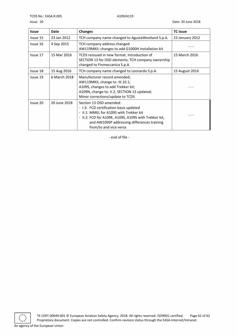
TCDS No.: EASA.R.005 A109/A119
Issue: 20 Date: 20 June 2018
TE.CERT.00049-001 © European Aviation Safety Agency, 2018. All rights reserved. ISO9001 certified. Page 62 of 62 Proprietary document. Copies are not controlled. Confirm revision status through the EASA-Internet/Intranet.
An agency of the European Union
Issue Date Changes TC issue
Issue 15 23 Jan 2012 TCH company name changed to AgustaWestland S.p.A. 23 January 2012
Issue 16 4 Sep 2015 TCH company address changed AW119MKII; changes to add G1000H installation kit
- - -
Issue 17 15 Mar 2016 TCDS reissued in new format. Introduction of SECTION 13 for OSD elements; TCH company ownership changed to Finmeccanica S.p.A.
15 March 2016
Issue 18 15 Aug 2016 TCH company name changed to Leonardo S.p.A. 15 August 2016
Issue 19 6 March 2018 Manufacturer record amended; AW119MKII, change to: III.10.1; A109S, changes to add Trekker kit; A109N, change to: V.2; SECTION 13 updated; Minor corrections/update to TCDS
- - -
Issue 20 20 June 2018 Section 13 OSD amended: - I.3: FCD certification basis updated - II.1: MMEL for A109S with Trekker kit - II.2: FCD for A109E, A109S, A109S with Trekker kit,
and AW109SP addressing differences training from/to and vice versa
- - -
- end of file -