type 2 push-through 37 ton log splitter assembly manual · type 2 push-through . 37 ton log...
TRANSCRIPT

Type 2 Push-Through 37 Ton Log Splitter Assembly Manual
Refer to this manual for the following models:
• RS37PT-LF09PC-16-1 • RS37PT-LF09EC-16-1 • RS37PT-LF09EC-16-2 • RS37PT-LF13EC-22-1 • RS37PT-LF13EC-22-2 • RS37PT-LF15EC-22-1 • RS37PT-LF15EC-22-2

Welcome to RuggedMade. This manual explains how to assemble your new log splitter. Please read this manual completely before assembling your splitter. Certain components must be installed in a specific sequence. The splitter arrives in a wooden crate containing all of the components and hardware that you will need. If you purchased the optional log lift and log catcher tray kit, it will arrive in a separate crate. You will need some basic tools, hydraulic fluid, engine oil, and PTFE thread seal tape. You will also need a battery if you purchased the optional electric start kit. We recommend a high quality 12N9-4B-1 12-volt battery. This will fit in the battery tray. See detailed battery spec at the end of this manual.
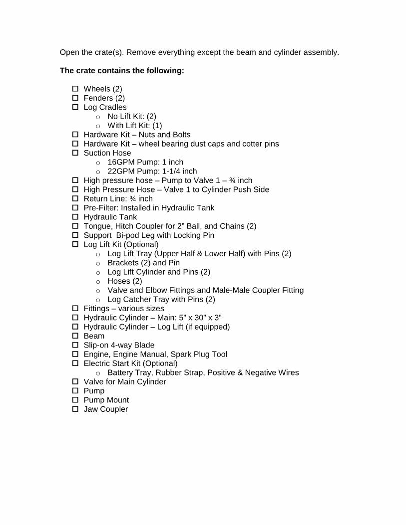
Open the crate(s). Remove everything except the beam and cylinder assembly. The crate contains the following: Wheels (2) Fenders (2) Log Cradles
o No Lift Kit: (2) o With Lift Kit: (1)
Hardware Kit – Nuts and Bolts Hardware Kit – wheel bearing dust caps and cotter pins Suction Hose
o 16GPM Pump: 1 inch o 22GPM Pump: 1-1/4 inch
High pressure hose – Pump to Valve 1 – ¾ inch High Pressure Hose – Valve 1 to Cylinder Push Side Return Line: ¾ inch Pre-Filter: Installed in Hydraulic Tank Hydraulic Tank Tongue, Hitch Coupler for 2” Ball, and Chains (2) Support Bi-pod Leg with Locking Pin Log Lift Kit (Optional)
o Log Lift Tray (Upper Half & Lower Half) with Pins (2) o Brackets (2) and Pin o Log Lift Cylinder and Pins (2) o Hoses (2) o Valve and Elbow Fittings and Male-Male Coupler Fitting o Log Catcher Tray with Pins (2)
Fittings – various sizes Hydraulic Cylinder – Main: 5” x 30” x 3” Hydraulic Cylinder – Log Lift (if equipped) Beam Slip-on 4-way Blade Engine, Engine Manual, Spark Plug Tool Electric Start Kit (Optional)
o Battery Tray, Rubber Strap, Positive & Negative Wires Valve for Main Cylinder Pump Pump Mount Jaw Coupler
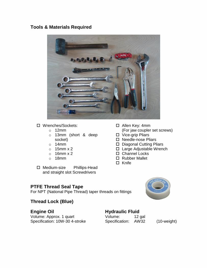
Tools & Materials Required Wrenches/Sockets:
o 12mm o 13mm (short & deep
socket) o 14mm o 15mm x 2 o 16mm x 2 o 18mm
Medium-size Phillips-Head
and straight slot Screwdrivers
Allen Key: 4mm (For jaw coupler set screws)
Vice-grip Pliars Needle-nose Pliars Diagonal Cutting Pliars Large Adjustable Wrench Channel Locks Rubber Mallet Knife
PTFE Thread Seal Tape For NPT (National Pipe Thread) taper threads on fittings Thread Lock (Blue) Engine Oil Volume: Approx. 1 quart Specification: 10W-30 4-stroke
Hydraulic Fluid Volume: 12 gal Specification: AW32 (10-weight)
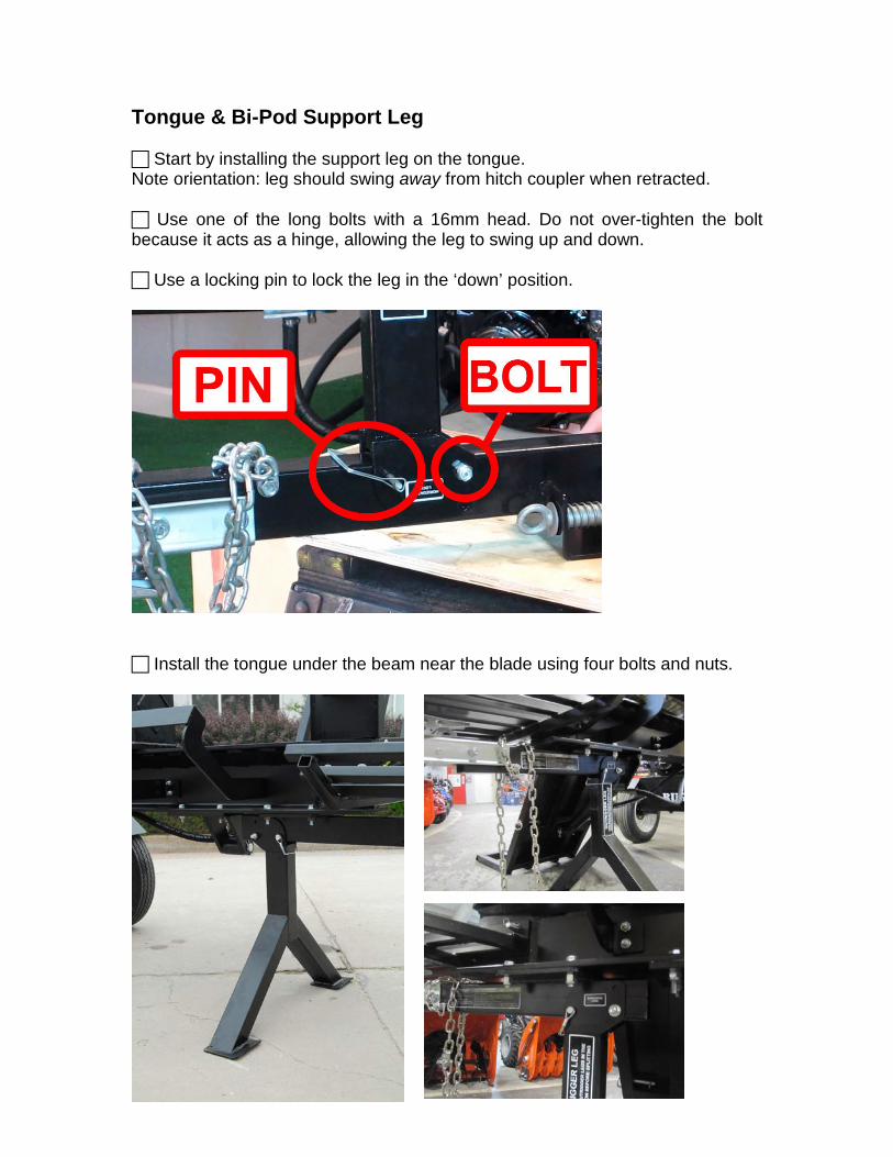
Tongue & Bi-Pod Support Leg Start by installing the support leg on the tongue. Note orientation: leg should swing away from hitch coupler when retracted. Use one of the long bolts with a 16mm head. Do not over-tighten the bolt because it acts as a hinge, allowing the leg to swing up and down. Use a locking pin to lock the leg in the ‘down’ position.
Install the tongue under the beam near the blade using four bolts and nuts.

Fenders Install the two fenders on the hydraulic tank. Use the 4 short bolts with 13mm heads from the hardware kit.
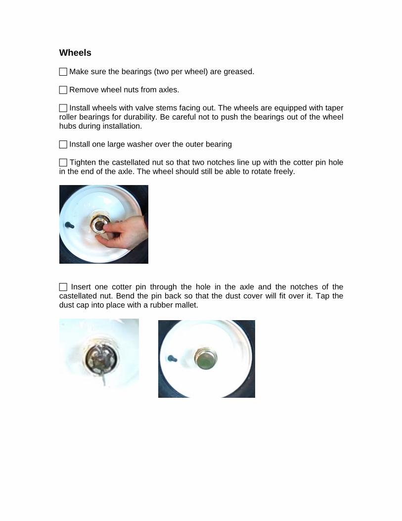
Wheels Make sure the bearings (two per wheel) are greased. Remove wheel nuts from axles. Install wheels with valve stems facing out. The wheels are equipped with taper roller bearings for durability. Be careful not to push the bearings out of the wheel hubs during installation. Install one large washer over the outer bearing Tighten the castellated nut so that two notches line up with the cotter pin hole in the end of the axle. The wheel should still be able to rotate freely.
Insert one cotter pin through the hole in the axle and the notches of the castellated nut. Bend the pin back so that the dust cover will fit over it. Tap the dust cap into place with a rubber mallet.
Frame-and-Cylinder Assembly Use an engine hoist, forklift, or other means to safely lift the beam out of the crate. Maintain a horizontal orientation.
NOTE: Use caution while maneuvering beam. Never place any parts of your body under it – Beam is extremely heavy!
Position the hydraulic tank (with wheels installed) under the rear of the beam. Line up the holes on the mounting plate on top of the tank with the holes in the bottom of the beam. There are multiple sets of holes. This allows varying amounts of room for the operator to stand between the log lift and the hydraulic tank. Keep in mind, the farther away from the blade you install the tank, the heavier the front of the splitter will be. We recommend installing the tank using the holes closest to the front (blade end) of the splitter. For additional standing room, use the set of holes second closest to the front of the splitter. Bolt the tongue and support leg assembly to the bottom of the blade end of the beam. After the tank and tongue are bolted to the beam, lower the splitter to the ground. Make sure the support leg is locked in the down position.

Log Cradle Install both log cradles by passing the bolts through both cradles and the vertical web of the I-beam. If your splitter is equipped with a log lift, install the single provided log cradle opposite the log lift at the same time as installing the log lift bracket. NOTE: The bolts go through the log lift bracket, the vertical part of the I-beam, and the log cradle.
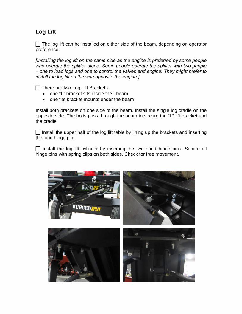
Log Lift The log lift can be installed on either side of the beam, depending on operator preference. [Installing the log lift on the same side as the engine is preferred by some people who operate the splitter alone. Some people operate the splitter with two people – one to load logs and one to control the valves and engine. They might prefer to install the log lift on the side opposite the engine.] There are two Log Lift Brackets:
• one “L” bracket sits inside the I-beam • one flat bracket mounts under the beam
Install both brackets on one side of the beam. Install the single log cradle on the opposite side. The bolts pass through the beam to secure the “L” lift bracket and the cradle. Install the upper half of the log lift table by lining up the brackets and inserting the long hinge pin. Install the log lift cylinder by inserting the two short hinge pins. Secure all hinge pins with spring clips on both sides. Check for free movement.
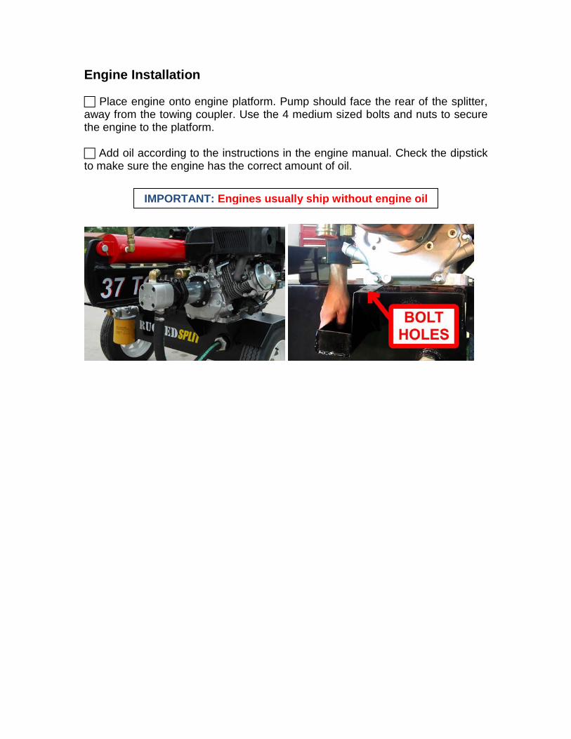
Engine Installation Place engine onto engine platform. Pump should face the rear of the splitter, away from the towing coupler. Use the 4 medium sized bolts and nuts to secure the engine to the platform. Add oil according to the instructions in the engine manual. Check the dipstick to make sure the engine has the correct amount of oil.
IMPORTANT: Engines usually ship without engine oil
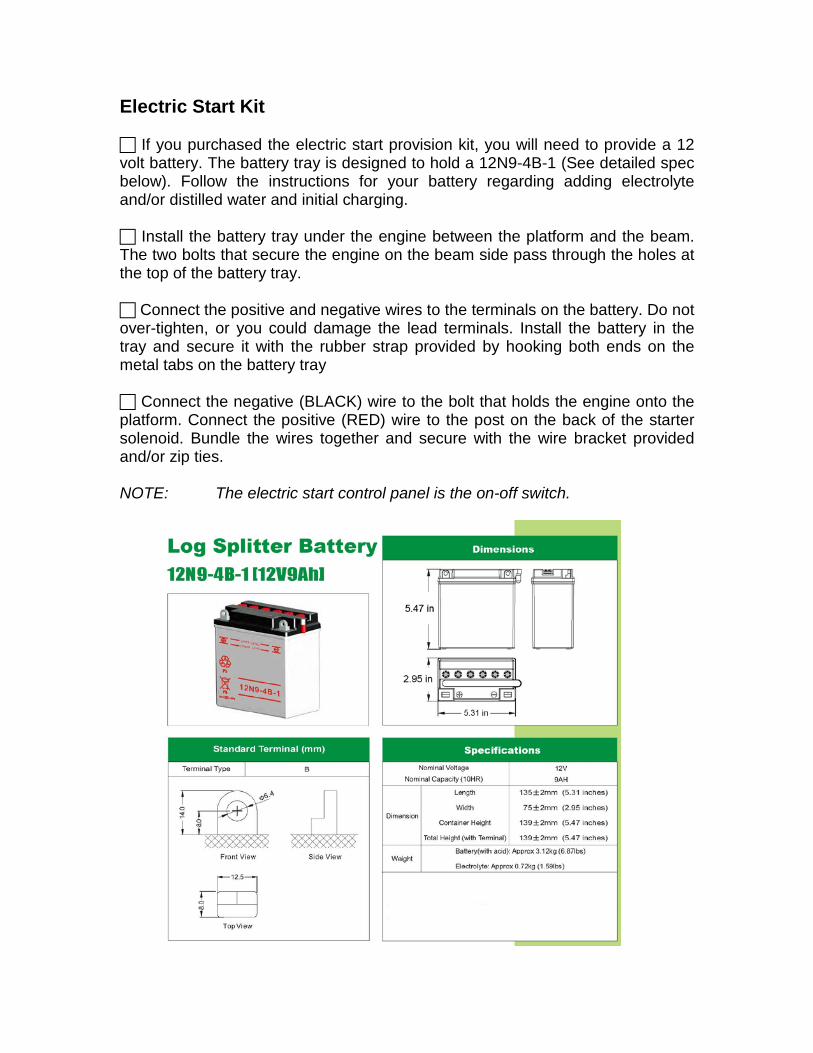
Electric Start Kit If you purchased the electric start provision kit, you will need to provide a 12 volt battery. The battery tray is designed to hold a 12N9-4B-1 (See detailed spec below). Follow the instructions for your battery regarding adding electrolyte and/or distilled water and initial charging. Install the battery tray under the engine between the platform and the beam. The two bolts that secure the engine on the beam side pass through the holes at the top of the battery tray. Connect the positive and negative wires to the terminals on the battery. Do not over-tighten, or you could damage the lead terminals. Install the battery in the tray and secure it with the rubber strap provided by hooking both ends on the metal tabs on the battery tray Connect the negative (BLACK) wire to the bolt that holds the engine onto the platform. Connect the positive (RED) wire to the post on the back of the starter solenoid. Bundle the wires together and secure with the wire bracket provided and/or zip ties. NOTE: The electric start control panel is the on-off switch.
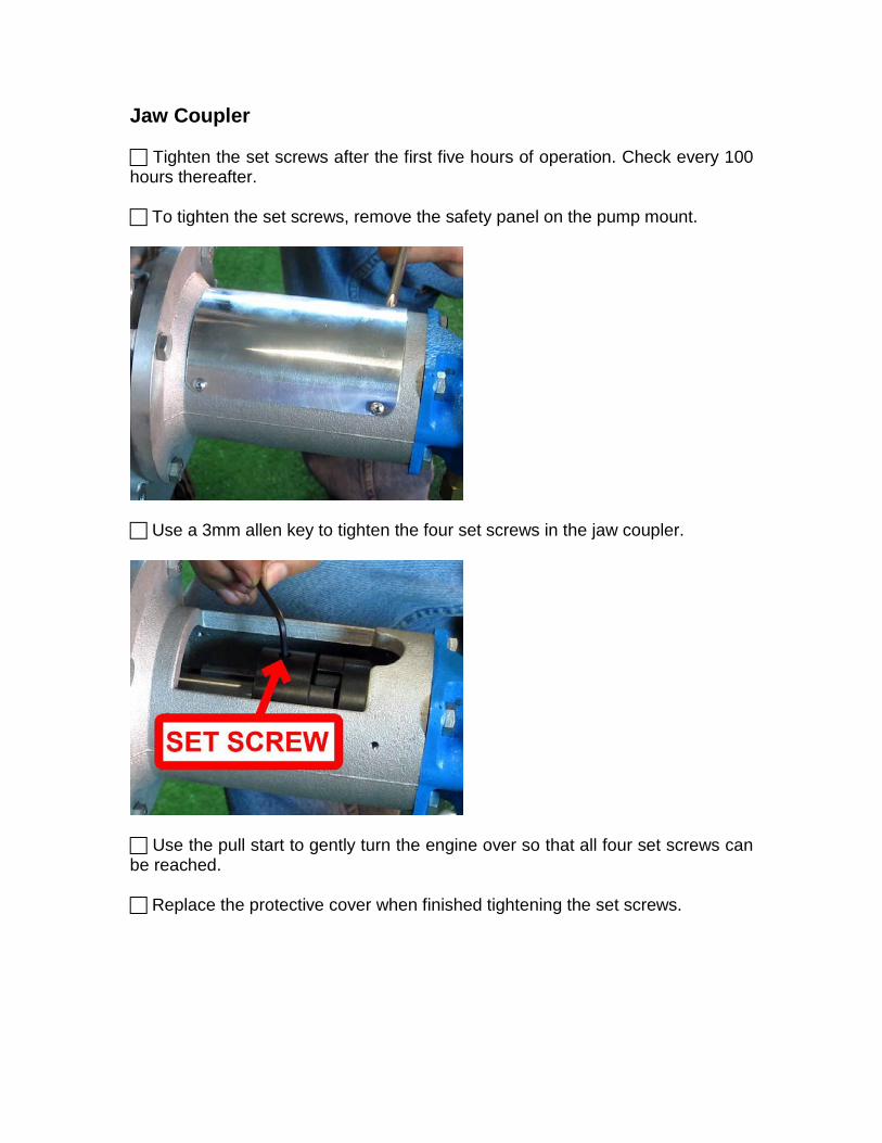
Jaw Coupler Tighten the set screws after the first five hours of operation. Check every 100 hours thereafter. To tighten the set screws, remove the safety panel on the pump mount.
Use a 3mm allen key to tighten the four set screws in the jaw coupler.
Use the pull start to gently turn the engine over so that all four set screws can be reached. Replace the protective cover when finished tightening the set screws.
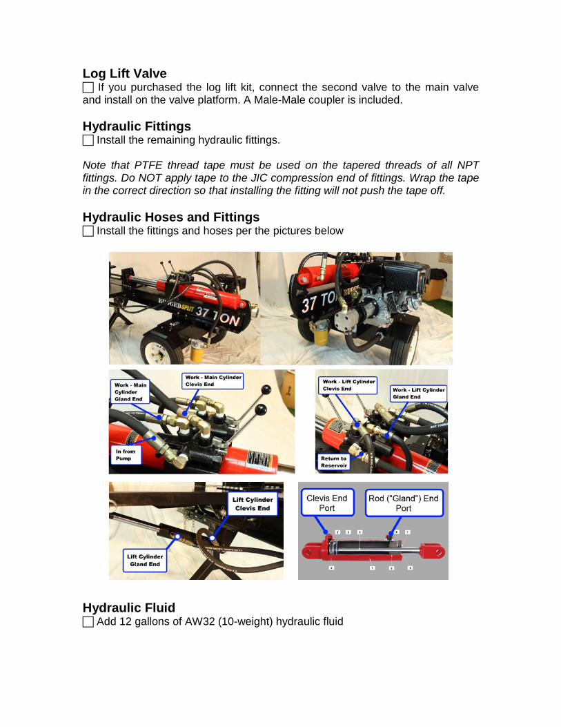
Log Lift Valve If you purchased the log lift kit, connect the second valve to the main valve and install on the valve platform. A Male-Male coupler is included. Hydraulic Fittings Install the remaining hydraulic fittings. Note that PTFE thread tape must be used on the tapered threads of all NPT fittings. Do NOT apply tape to the JIC compression end of fittings. Wrap the tape in the correct direction so that installing the fitting will not push the tape off. Hydraulic Hoses and Fittings Install the fittings and hoses per the pictures below Hydraulic Fluid Add 12 gallons of AW32 (10-weight) hydraulic fluid
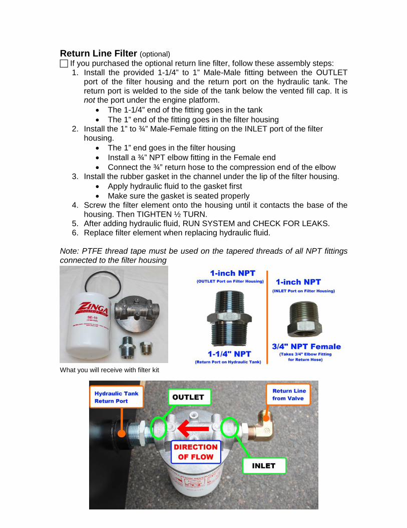
Return Line Filter (optional) If you purchased the optional return line filter, follow these assembly steps:
1. Install the provided 1-1/4” to 1” Male-Male fitting between the OUTLET port of the filter housing and the return port on the hydraulic tank. The return port is welded to the side of the tank below the vented fill cap. It is not the port under the engine platform.
• The 1-1/4” end of the fitting goes in the tank • The 1” end of the fitting goes in the filter housing
2. Install the 1” to ¾” Male-Female fitting on the INLET port of the filter housing.
• The 1” end goes in the filter housing • Install a ¾” NPT elbow fitting in the Female end • Connect the ¾” return hose to the compression end of the elbow
3. Install the rubber gasket in the channel under the lip of the filter housing. • Apply hydraulic fluid to the gasket first • Make sure the gasket is seated properly
4. Screw the filter element onto the housing until it contacts the base of the housing. Then TIGHTEN ½ TURN.
5. After adding hydraulic fluid, RUN SYSTEM and CHECK FOR LEAKS. 6. Replace filter element when replacing hydraulic fluid.
Note: PTFE thread tape must be used on the tapered threads of all NPT fittings connected to the filter housing What you will receive with filter kit
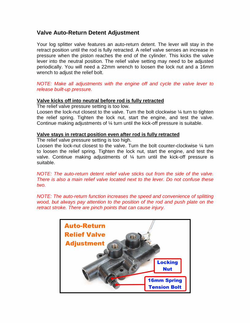
Valve Auto-Return Detent Adjustment Your log splitter valve features an auto-return detent. The lever will stay in the retract position until the rod is fully retracted. A relief valve senses an increase in pressure when the piston reaches the end of the cylinder. This kicks the valve lever into the neutral position. The relief valve setting may need to be adjusted periodically. You will need a 22mm wrench to loosen the lock nut and a 16mm wrench to adjust the relief bolt. NOTE: Make all adjustments with the engine off and cycle the valve lever to release built-up pressure. Valve kicks off into neutral before rod is fully retracted The relief valve pressure setting is too low. Loosen the lock-nut closest to the valve. Turn the bolt clockwise ¼ turn to tighten the relief spring. Tighten the lock nut, start the engine, and test the valve. Continue making adjustments of ¼ turn until the kick-off pressure is suitable. Valve stays in retract position even after rod is fully retracted The relief valve pressure setting is too high. Loosen the lock-nut closest to the valve. Turn the bolt counter-clockwise ¼ turn to loosen the relief spring. Tighten the lock nut, start the engine, and test the valve. Continue making adjustments of ¼ turn until the kick-off pressure is suitable. NOTE: The auto-return detent relief valve sticks out from the side of the valve. There is also a main relief valve located next to the lever. Do not confuse these two. NOTE: The auto-return function increases the speed and convenience of splitting wood, but always pay attention to the position of the rod and push plate on the retract stroke. There are pinch points that can cause injury.
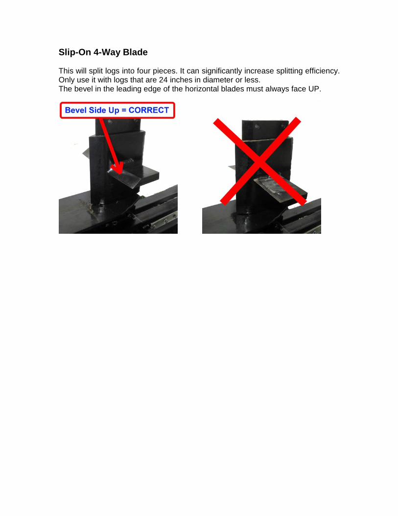
Slip-On 4-Way Blade This will split logs into four pieces. It can significantly increase splitting efficiency. Only use it with logs that are 24 inches in diameter or less. The bevel in the leading edge of the horizontal blades must always face UP.
Towing Use caution when transporting the splitter. It does not have a suspension, so maximum safe towing speed is 40mph on smooth roads, and lower for uneven road surfaces. Be sure to attach the safety chains, secure the log catcher and outer panel of the log lift, and lock the support leg in the upright position when towing. Check tire pressure before towing. Before towing, turn off the fuel petcock and run the engine until it stops. This will prevent fuel from passing through the carburetor and entering the crankcase of the engine.

RuggedMade by IMS 7 Market Street
Rockland, MA 02370 Tel: 1-855-8-RUGGED (855-878-4433)
E-Mail: [email protected] Website: www.ruggedmade.com